EP4102646A1 - Lens antenna, detection apparatus, and communication apparatus - Google Patents
Lens antenna, detection apparatus, and communication apparatus Download PDFInfo
- Publication number
- EP4102646A1 EP4102646A1 EP20923807.0A EP20923807A EP4102646A1 EP 4102646 A1 EP4102646 A1 EP 4102646A1 EP 20923807 A EP20923807 A EP 20923807A EP 4102646 A1 EP4102646 A1 EP 4102646A1
- Authority
- EP
- European Patent Office
- Prior art keywords
- radiation
- unit
- units
- lens antenna
- beam radiation
- Prior art date
- Legal status (The legal status is an assumption and is not a legal conclusion. Google has not performed a legal analysis and makes no representation as to the accuracy of the status listed.)
- Granted
Links
Images


Classifications
-
- H—ELECTRICITY
- H01—ELECTRIC ELEMENTS
- H01Q—ANTENNAS, i.e. RADIO AERIALS
- H01Q1/00—Details of, or arrangements associated with, antennas
- H01Q1/27—Adaptation for use in or on movable bodies
- H01Q1/32—Adaptation for use in or on road or rail vehicles
- H01Q1/3208—Adaptation for use in or on road or rail vehicles characterised by the application wherein the antenna is used
- H01Q1/3233—Adaptation for use in or on road or rail vehicles characterised by the application wherein the antenna is used particular used as part of a sensor or in a security system, e.g. for automotive radar, navigation systems
-
- H—ELECTRICITY
- H01—ELECTRIC ELEMENTS
- H01Q—ANTENNAS, i.e. RADIO AERIALS
- H01Q19/00—Combinations of primary active antenna elements and units with secondary devices, e.g. with quasi-optical devices, for giving the antenna a desired directional characteristic
- H01Q19/06—Combinations of primary active antenna elements and units with secondary devices, e.g. with quasi-optical devices, for giving the antenna a desired directional characteristic using refracting or diffracting devices, e.g. lens
- H01Q19/062—Combinations of primary active antenna elements and units with secondary devices, e.g. with quasi-optical devices, for giving the antenna a desired directional characteristic using refracting or diffracting devices, e.g. lens for focusing
-
- H—ELECTRICITY
- H01—ELECTRIC ELEMENTS
- H01Q—ANTENNAS, i.e. RADIO AERIALS
- H01Q15/00—Devices for reflection, refraction, diffraction or polarisation of waves radiated from an antenna, e.g. quasi-optical devices
- H01Q15/02—Refracting or diffracting devices, e.g. lens, prism
-
- H—ELECTRICITY
- H01—ELECTRIC ELEMENTS
- H01Q—ANTENNAS, i.e. RADIO AERIALS
- H01Q19/00—Combinations of primary active antenna elements and units with secondary devices, e.g. with quasi-optical devices, for giving the antenna a desired directional characteristic
- H01Q19/06—Combinations of primary active antenna elements and units with secondary devices, e.g. with quasi-optical devices, for giving the antenna a desired directional characteristic using refracting or diffracting devices, e.g. lens
-
- H—ELECTRICITY
- H01—ELECTRIC ELEMENTS
- H01Q—ANTENNAS, i.e. RADIO AERIALS
- H01Q21/00—Antenna arrays or systems
- H01Q21/06—Arrays of individually energised antenna units similarly polarised and spaced apart
- H01Q21/061—Two dimensional planar arrays
- H01Q21/065—Patch antenna array
-
- H—ELECTRICITY
- H01—ELECTRIC ELEMENTS
- H01Q—ANTENNAS, i.e. RADIO AERIALS
- H01Q21/00—Antenna arrays or systems
- H01Q21/24—Combinations of antenna units polarised in different directions for transmitting or receiving circularly and elliptically polarised waves or waves linearly polarised in any direction
-
- H—ELECTRICITY
- H01—ELECTRIC ELEMENTS
- H01Q—ANTENNAS, i.e. RADIO AERIALS
- H01Q25/00—Antennas or antenna systems providing at least two radiating patterns
- H01Q25/002—Antennas or antenna systems providing at least two radiating patterns providing at least two patterns of different beamwidth; Variable beamwidth antennas
-
- H—ELECTRICITY
- H01—ELECTRIC ELEMENTS
- H01Q—ANTENNAS, i.e. RADIO AERIALS
- H01Q3/00—Arrangements for changing or varying the orientation or the shape of the directional pattern of the waves radiated from an antenna or antenna system
- H01Q3/24—Arrangements for changing or varying the orientation or the shape of the directional pattern of the waves radiated from an antenna or antenna system varying the orientation by switching energy from one active radiating element to another, e.g. for beam switching
- H01Q3/247—Arrangements for changing or varying the orientation or the shape of the directional pattern of the waves radiated from an antenna or antenna system varying the orientation by switching energy from one active radiating element to another, e.g. for beam switching by switching different parts of a primary active element
-
- H—ELECTRICITY
- H01—ELECTRIC ELEMENTS
- H01Q—ANTENNAS, i.e. RADIO AERIALS
- H01Q5/00—Arrangements for simultaneous operation of antennas on two or more different wavebands, e.g. dual-band or multi-band arrangements
- H01Q5/40—Imbricated or interleaved structures; Combined or electromagnetically coupled arrangements, e.g. comprising two or more non-connected fed radiating elements
- H01Q5/42—Imbricated or interleaved structures; Combined or electromagnetically coupled arrangements, e.g. comprising two or more non-connected fed radiating elements using two or more imbricated arrays
Definitions
- This application relates to the field of communication technologies, and in particular, to a lens antenna, a detection apparatus, and a communication apparatus.
- a spherical wave emitted by a point light source on a focal point of a lens is converted into a plane wave after refraction of the lens.
- a lens antenna with an electromagnetic wave is fabricated by using a same principle as that of the optical lens.
- the lens antenna includes a lens and a feed source placed on a focal point of the lens, and is an antenna that converts, by using the lens, a spherical wave or a cylindrical wave of the feed source into a plane wave to obtain a pen-shaped, sector-shaped, or another-shaped beam.
- All radar antennas in a conventional technology are lens antennas, but all radar antennas in the conventional technology are narrow beam antennas. Beam scanning is implemented by switching four beams. However, due to a limitation of a beam width, this radar can only be used for long-range target detection. A short-range target needs to be detected by another radar. A function of this radar is single.
- This application provides a lens antenna, a detection apparatus, and a communication apparatus, to improve a detection effect of the detection apparatus.
- a lens antenna is provided and is applied to a detection apparatus.
- the lens antenna includes a feed source, a radio frequency switch, at least two narrow beam radiation units, and a wide beam radiation unit, where the feed source is configured to selectively send a signal to the narrow beam radiation unit and the wide beam radiation unit.
- the feed source may selectively feed any narrow beam radiation unit or the wide beam radiation unit by using the radio frequency switch.
- the narrow beam radiation unit or the wide beam radiation unit may be connected to the feed source by switching of the radio frequency switch.
- a first radiation region of the wide beam radiation unit covers a second radiation region of each narrow beam radiation unit.
- the wide beam radiation unit includes a plurality of radiation sub-units.
- the plurality of radiation sub-units are connected to the radio frequency switch by using a power splitter. In this way, radiation of the plurality of radiation sub-units forms a wide beam.
- switching between a narrow beam and a wide beam can be implemented by using the radio frequency switch.
- the wide beam may be used.
- the narrow beam may be used through switching. This improves a detection effect of the detection apparatus.
- a sum of regions covered by all the second radiation regions is the same as the first radiation region.
- the first radiation region may be alternatively greater than the regions covered by all the second radiation regions.
- the at least two narrow beam radiation units are disposed around the wide beam radiation unit. In this way, regions covered by the narrow beam and the wide beam can overlap each other.
- a distance between each of the narrow beam radiation units and any adjacent radiation sub-unit is not less than a wavelength corresponding to an operating frequency band of the lens antenna. This reduces energy coupling between different radiation units.
- the narrow beam radiation unit and the wide beam radiation unit may be arranged in different manners.
- the plurality of narrow beam radiation units are arranged in two rows.
- the plurality of radiation sub-units are arranged in a single row, and are located between the two rows of the narrow beam radiation units.
- each radiation unit may be arranged in a plurality of manners, and may be specifically disposed based on a radiation direction. For example, one diagonal line of each narrow beam radiation unit in each row is parallel to a first direction. The first direction is an arrangement direction of each row of narrow beam radiation units. One diagonal line of each radiation sub-unit is parallel to the first direction.
- the lens antenna is a dual-polarized antenna; and/or each narrow beam radiation unit is a square radiation patch; and/or each radiation sub-unit is also a square radiation patch. This can implement dual-polarization radiation.
- a notch for increasing a beam width is provided on a side of each radiation sub-unit, to enlarge a coverage region of the wide beam.
- a notch that reduces an area of the radiation sub-unit is provided on the side of each radiation sub-unit.
- the notch is a triangle.
- the notch may further increase a distance between the radiation sub-unit and the narrow beam radiation unit, thereby reducing coupling.
- a substrate is further included.
- the substrate includes a first surface and a second surface that are opposite to each other.
- the narrow beam radiation unit and the wide beam radiation unit are disposed on the first surface.
- the power splitter, the radio frequency switch, and the feed source are disposed on the second surface.
- the lens antenna is carried by the substrate.
- the lens antenna further includes a stratum, and the stratum is embedded in the substrate and is located between the first surface and the second surface.
- the power splitter is an equal-power splitter. Therefore, the plurality of radiation sub-units have equal power.
- the plurality of radiation sub-units have equal power and a same phase, to improve coverage of a wide beam formed after superposition.
- the power splitter may be a microstrip power splitter, a waveguide power splitter, or a coaxial power splitter.
- a connection between the radiation unit and the feed source is implemented by using different power splitters.
- a detection apparatus includes a processor and any one of the foregoing lens antennas connected to the processor.
- switching between a narrow beam and a wide beam may be implemented by using a radio frequency switch.
- the wide beam may be used.
- the narrow beam may be used through switching. This improves a detection effect of the detection apparatus.
- a communication apparatus including a processor and any one of the foregoing lens antennas connected to the processor.
- switching between a narrow beam and a wide beam may be implemented by using a radio frequency switch.
- the wide beam may be used.
- the narrow beam may be used through switching. This improves a detection effect of a detection apparatus.
- an intelligent vehicle including a vehicle body and the foregoing detection apparatus disposed in the vehicle body.
- switching between a narrow beam and a wide beam can be implemented by using a radio frequency switch.
- the wide beam may be used.
- the narrow beam may be used through switching. This improves a detection effect of the detection apparatus.
- the lens antenna provided in this embodiment of this application may be applied to a detection apparatus or a communication apparatus.
- the detection apparatus may be a millimeter wave radar or another type of radar.
- the communication apparatus may be a common communication apparatus that can transmit and receive signals, for example, a base station or a router.
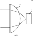
- FIG. 1 shows a specific lens antenna 100.
- the lens antenna 100 provided in this embodiment of this application includes a lens 20 and an antenna 10 placed on a focal point of the lens 20.
- the lens 20 can enable a spherical wave emitted by a point light source placed on a focal point of the lens 20 to be converted into a plane wave after refraction of the lens 20.
- the lens antenna 100 is fabricated by using a same principle as that of the optical lens 20.
- the lens antenna 100 converts a spherical wave or a cylindrical wave of the antenna 10 into a plane wave by using the lens 20 to obtain a pen-shaped, sector-shaped, or another-shaped beam.
- the lens 20 may be in different forms, for example, the lens 20 is a planar lens 20 or a curved lens 20.
- the lens antenna 100 provided in this embodiment of this application only involves a change of the antenna 10.
- the lens 20 in the lens antenna 100 may be an existing known lens 20, and details are not described herein.
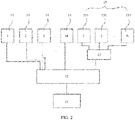
- FIG. 2 is a block diagram of an antenna structure of a lens antenna according to an embodiment of this application.
- the antenna includes a feed source 11, a radio frequency switch 12, and radiation units.
- the feed source 11 is connected to the radio frequency switch 12 by using a circuit.
- the radio frequency switch 12 is a selector switch.
- the feed source 11 may be selectively connected to any radiation unit.
- the radio frequency switch 12 is a single-pole multi-throw switch.
- a movable terminal of the radio frequency switch 12 is connected to the feed source 11 by using a circuit.
- a non-movable terminal of the radio frequency switch 12 includes a plurality of connection points, and the plurality of connection points are correspondingly connected to the radiation units one by one by using circuits.
- the plurality of radiation units may be classified into a narrow beam radiation unit 14 and a wide beam radiation unit 15 based on function division.
- a quantity of narrow beam radiation units 14 may be set based on a requirement, and there is one wide beam radiation unit 15.
- FIG. 2 shows only an example of types of the radiation units, and does not specifically indicate an actual arrangement manner of the radiation units.
- the wide beam radiation unit 15 includes a plurality of radiation sub-units 151.
- FIG. 2 shows M radiation sub-units 151, where M is a positive integer greater than 2.
- a specific quantity of the radiation sub-units 151 may be limited based on a range that needs to be covered by the wide beam radiation unit 15.
- the plurality of radiation sub-units 151 are connected by using a power splitter 13.
- One terminal of the power splitter 13 is connected to the radio frequency switch 12.
- the other terminal of the power splitter 13 has a plurality of ports, and the plurality of ports are correspondingly connected to the plurality of radiation sub-units 151 of the wide beam radiation unit 15 one by one.
- FIG. 2 is a block diagram of a structure of a connection between the radiation unit of the lens antenna being a single-polarized antenna and the feed source 11.
- the lens antenna is a dual-polarized antenna, there are two feed sources 11, two radio frequency switches 12, and two power splitters 13.
- the two feed sources 11 are separately configured to feed one polarization direction of the radiation unit.
- a feeding circuit in each polarization direction is the same as a feeding circuit of the single-polarized antenna.
- FIG. 3 is a schematic diagram of radiation regions of the wide beam radiation unit 15 and the narrow beam radiation units 14.
- N second radiation regions a 1 , a 2 , a 3 , ..., and a n , and one first radiation region A are shown.
- the first radiation region is a radiation region of the wide beam radiation unit 15, and the second radiation region is a radiation region of each narrow beam radiation unit 14.
- the first radiation region of the wide beam radiation unit 15 is a radiation region formed by overlapping radiation regions of the plurality of radiation sub-units. It can be learned from FIG. 3 that the first radiation region A overlaps each second radiation region, and the first radiation region A of the wide beam radiation unit 15 covers the second radiation region of each narrow beam radiation unit 14.
- the first radiation region A may be greater than or equal to a sum of the second radiation regions.
- the sum of the second radiation regions is a sum of superposition of regions covered by all the second radiation regions.
- the sum of regions covered by the second radiation regions includes non-overlapped regions between the second radiation regions and the overlapped region between the second radiation regions.
- an overlapped region of any two second radiation regions is b
- the first radiation region may be alternatively greater than the sum of the regions covered by all the second radiation regions.
- the lens antenna includes one substrate 16.
- the substrate 16 may use different materials, for example, a printed circuit board or another type of circuit board. This is not specifically limited herein.
- the substrate 16 is a structure that carries a component of the antenna. As shown in FIG. 4 , the substrate 16 has a first surface 161.
- the wide beam radiation unit and the narrow beam radiation units 14 are all disposed on the first surface 161 of the substrate 16. When the wide beam radiation unit and the narrow beam radiation units 14 are specifically disposed, it should be ensured that the first radiation region of the wide beam radiation unit can cover the second radiation regions of narrow beams.
- M narrow beam radiation units 14 may be disposed around the wide beam radiation unit.
- the wide beam radiation unit is located in the middle, and the M narrow beam radiation units 14 are disposed outside.
- an installation structure is beautiful, and the first radiation region of the wide beam radiation unit can more easily cover second radiation regions of the M narrow beam radiation units.
- an around disposing manner is only an example.
- the wide beam radiation unit and the narrow beam radiation unit do not require a physical installation structure.
- the first radiation region can also cover all second radiation regions.
- the plurality of radiation sub-units 151 are arranged in a single row, and are located between two rows of the narrow beam radiation units 14. As shown in FIG.
- the 10 narrow beam radiation units 14 are arranged in two rows in a direction b.
- Each row of narrow beam radiation units 14 includes five narrow beam radiation units 14, and each row of narrow beam radiation units 14 is arranged in a direction a.
- the direction a is a first direction, and the first direction is a length direction of the substrate 16.
- the direction b is a second direction, and the second direction is a width direction of the substrate 16.
- Five radiation sub-units 151 are arranged in the direction a, and the radiation sub-units 151 are located between the two rows of narrow beam radiation units 14. That is, the two rows of narrow beam radiation units 14 surround one row of radiation sub-units 151.
- the four radiation sub-units 151 are disposed between gaps of the narrow beam radiation units 14. As shown in FIG. 4 , one radiation sub-unit 151 is located in space enclosed by four narrow beam radiation units 14. This can effectively reduce a space area occupied by the radiation units.
- the radiation sub-unit 151 and the narrow beam radiation unit 14 may be fastened to the substrate 16 in a patch manner.
- a metal layer may be formed through vapor deposition on the first surface 161 of the substrate 16, and then the metal layer is etched to form the radiation sub-unit 151 and the wide beam radiation unit.
- the lens antenna is a dual-polarized antenna
- the radiation sub-unit 151 and the narrow beam radiation unit 14 of the lens antenna are all square radiation units, so as to ensure that polarization directions of each radiation unit are perpendicular to each other.
- two adjacent sides of any radiation unit are separately connected to one pin, and the two pins are respectively corresponding to feeds in two opposite polarization directions.
- sizes of the wide beam radiation unit and the narrow beam radiation unit 14 may be equal or unequal.
- the narrow beam radiation unit 14 and the radiation sub-unit 151 may be arranged in different manners.
- a diagonal line of each narrow beam radiation unit 14 is parallel to the direction a
- a diagonal line of each radiation sub-unit 151 is parallel to the direction a.
- the narrow beam radiation unit 14 may overlap in both the direction b and the direction a. Therefore, an area occupied by the radiation units on the first surface 161 can be reduced.
- the wide beam radiation unit and the narrow beam radiation unit 14 is only a specific example.
- the wide beam radiation unit and the narrow beam radiation unit 14 may be alternatively disposed in another arrangement manner.
- a specific arrangement manner of the narrow beam radiation unit 14 and the wide beam radiation unit may be determined based on a region that needs to be covered by the lens antenna. For example, when the radiation sub-unit 151 is to be determined, an equation between a composite beam of the radiation sub-unit 151 and a feeding amplitude and a phase of the radiation sub-unit 151 is obtained by using a calculation formula of array antenna beam combination.
- an arrangement manner of the radiation sub-units 151 is obtained by using a computer to search for and calculate an optimal solution for a feeding relationship of each radiation sub-unit 151 to meet a constraint.
- the foregoing calculation formula of array antenna beam combination and a formula used by the computer to search for and calculate the feed relationship of each radiation sub-unit 151 are common formulas in a conventional technology. Therefore, details are not described herein.
- a distance between each narrow beam radiation unit 14 and any adjacent radiation sub-unit 151 or narrow beam radiation unit 14 is not less than a wavelength ⁇ corresponding to an operating frequency band of the lens antenna.
- a distance between adjacent narrow beam radiation units 14 is d1
- a distance between the narrow beam radiation unit 14 and the radiation sub-unit 151 that are adjacent to each other is d2, where d1 ⁇ and d2 ⁇ .
- FIG. 5 is a bottom view of an antenna of a lens antenna according to an embodiment of this application.
- the substrate 16 further has a second surface 162.
- the power splitter 13, the radio frequency switch 12, and the feed source 11 in the antenna are disposed on the second surface 162.
- the second surface 162 and the first surface are two opposite surfaces.
- a quantity of components disposed on each surface may be reduced by using two different surfaces. This facilitates antenna arrangement.
- the lens antenna is a dual-polarized antenna, there are two feed sources 11, two power splitters 13, and two radio frequency switches 12.
- One feed source 11 is connected to the radiation sub-unit and the narrow beam radiation unit in one polarization direction by using one radio frequency switch 12.
- the other feed source 11 is connected to the radiation sub-unit and the narrow beam radiation unit in the other polarization direction by using the other radio frequency switch 12.
- each radiation sub-unit 151 is connected to one power splitter 13 in one polarization direction.
- the power splitter 13 is an equal-power splitter.
- the power splitter 13 is a quad power splitter 13.
- the power splitter 13 divides signals transmitted from the feed source 11 into four equal parts, and sends each equal part of signals to a corresponding connected radiation sub-unit.
- the four radiation sub-units have equal power.
- the power splitter 13 transmits a same phase signal to each radiation sub-unit 151, so that the four radiation sub-units have equal power and a same phase. Therefore, the wide beam radiation unit has a widest first radiation region.
- design of the power splitter 13 is simplified, and no additional power and phase adjustment units need to be inserted.
- the power splitter 13 is connected to the radiation sub-unit 151 in a corresponding equal power division manner, so that the radiation sub-units can also have equal power and a same phase.
- the power splitter 13 When the power splitter 13 is specifically disposed, different power splitters 13 may be used.
- the power splitter 13 may be a microstrip power splitter, a waveguide power splitter, or a coaxial power splitter, which can be applied to embodiments of this application.
- FIG. 6 is a schematic diagram of an internal structure.
- the radiation unit may be connected to the power splitter 13 or the radio frequency switch 12 through a via provided in the substrate 16.
- the narrow beam radiation unit 14 is connected to the radio frequency switch 12 through a first via 163
- the radiation sub-unit 151 is connected to the power splitter 13 through a second via 17.
- the antenna further includes a stratum, and the stratum is embedded in the substrate 16 and is located between the first surface 161 and the second surface 162.
- the radiation unit is separated from a feeding network (a circuit including the power splitter 13 and the radio frequency switch 12) by using the stratum.
- a feeding network a circuit including the power splitter 13 and the radio frequency switch 12
- the stratum is disposed between the first surface 161 and the second surface 162
- the first via 163 and the second via 164 separately pass through the stratum, but the first via 163 and the second via 164 are separately insulated from the stratum.
- the wide beam radiation unit may be connected to the feed source by using the radio frequency switch 12.
- the feed source covers the large first radiation region by using the wide beam radiation unit.
- the narrow beam radiation unit 14 corresponding to the region may be connected to the feed source by switching the switch, and the feed source covers the region that requires targeted communication by using the second radiation region of the narrow beam radiation unit 14.
- the wide beam radiation unit may not be disposed.
- the targeted communication can be implemented only by switching of the narrow beam radiation units 14.
- switching one by one causes low operating efficiency of the antenna. Therefore, after the wide beam radiation unit is first used to perform large range scanning, and then the region that requires targeted communication is determined, the narrow beam radiation unit 14 corresponding to the region can be directly switched. This can effectively improve operating efficiency of the antenna.
- FIG. 7 shows a second lens antenna according to an embodiment of this application.
- a difference between the lens antenna shown in FIG. 7 and the lens antenna shown in FIG. 3 lies in a different shape of a radiation unit.
- a notch 152 for increasing a beam width is provided on a side of each radiation sub-unit 151.
- a smaller area of a radiation unit indicates a larger radiation region corresponding to the radiation unit. Therefore, the notch 152 that reduces an area of the radiation sub-unit 151 is provided on the side of each radiation sub-unit 151. This can effectively reduce the area of the radiation sub-unit 151.
- the notch 152 of the radiation sub-unit 151 in FIG. 7 may be considered as a structure formed by cutting off a triangular notch 152 on each side of the square radiation sub-unit 151 shown in FIG. 4 . After a triangle is cut off on each side, the radiation sub-unit 151 forms a cross-star structure.
- another different shape of notch 152 may be used, for example, a trapezoidal notch 152 or an arc notch 152.
- an arrangement manner of the narrow beam radiation units 14 and the wide beam radiation unit in FIG. 7 is the same as that in FIG. 4 .
- One diagonal line of each narrow beam radiation unit 14 is parallel to a direction a, and one diagonal line of each radiation sub-unit 151 is parallel to the direction a.
- a diagonal line of the radiation sub-unit 151 is a line between two opposite end corners.
- FIG. 8 shows a third lens antenna according to an embodiment of this application.
- the lens antenna shown in FIG. 8 is a single-polarized antenna.
- a different shape may be selected as a shape of the radiation unit.
- shapes of narrow beam radiation units 14 and radiation sub-units 151 are all rectangular.
- the shapes of the narrow beam radiation units 14 and the radiation sub-units 151 may be alternatively square.
- a feed source is connected to the radiation sub-unit 151 by using one power splitter.
- the radiation sub-unit 151 may alternatively use the notch shown in FIG. 7 .
- the notch shown in FIG. 7 .
- FIG. 7 For a specific arrangement manner of the notch, refer to related descriptions in FIG. 7 . Details are not described herein again.
- FIG. 9 shows a detection apparatus according to an embodiment of this application.
- the detection apparatus provided in this embodiment of this application includes a processor 30 and any one of the foregoing lens antennas connected to the processor 30.
- the processor 30 is configured to process a signal of an antenna, and the processor 30 may include common components such as a radio frequency circuit, a filter, and a low-sound noise reducer.
- the processor 30 is connected to an antenna 10.
- the processor 30 processes a signal and sends a processed signal to the antenna 10, and the antenna 10 transmits the processed signal through a lens 20 to complete communication.
- switching between a narrow beam and a wide beam can be implemented by using a radio frequency switch.
- the wide beam may be used.
- the narrow beam may be used through switching. This improves a detection effect of the detection apparatus.
- An embodiment of this application further provides a communication apparatus, and the communication apparatus may be a base station, a router, or another apparatus that can implement communication.
- the communication apparatus includes a processor and any one of the foregoing lens antennas connected to the processor. Switching between a narrow beam and a wide beam can be implemented by using a radio frequency switch. When scanning needs to be performed, the wide beam may be used. When communication needs to be performed for a specific region, the narrow beam may be used through switching. This improves a detection effect of a detection apparatus.
- FIG. 10 shows an intelligent vehicle according to an embodiment of this application.
- the intelligent vehicle includes a vehicle body 200 and the foregoing detection apparatus 201 disposed in the vehicle body 200.
- the detection apparatus 201 in FIG. 10 is merely an example, and does not represent an actual arrangement location of the detection apparatus 201.
- switching between a narrow beam and a wide beam can be implemented by using a radio frequency switch.
- the wide beam may be used.
- the narrow beam may be used through switching. This improves a detection effect of the detection apparatus 201.
Landscapes
- Physics & Mathematics (AREA)
- Electromagnetism (AREA)
- Engineering & Computer Science (AREA)
- Computer Security & Cryptography (AREA)
- Radar, Positioning & Navigation (AREA)
- Remote Sensing (AREA)
- Aerials With Secondary Devices (AREA)
- Variable-Direction Aerials And Aerial Arrays (AREA)
Abstract
Description
- This application relates to the field of communication technologies, and in particular, to a lens antenna, a detection apparatus, and a communication apparatus.
- In optics, a spherical wave emitted by a point light source on a focal point of a lens is converted into a plane wave after refraction of the lens. A lens antenna with an electromagnetic wave is fabricated by using a same principle as that of the optical lens. The lens antenna includes a lens and a feed source placed on a focal point of the lens, and is an antenna that converts, by using the lens, a spherical wave or a cylindrical wave of the feed source into a plane wave to obtain a pen-shaped, sector-shaped, or another-shaped beam.
- All radar antennas in a conventional technology are lens antennas, but all radar antennas in the conventional technology are narrow beam antennas. Beam scanning is implemented by switching four beams. However, due to a limitation of a beam width, this radar can only be used for long-range target detection. A short-range target needs to be detected by another radar. A function of this radar is single.
- This application provides a lens antenna, a detection apparatus, and a communication apparatus, to improve a detection effect of the detection apparatus.
- According to a first aspect, a lens antenna is provided and is applied to a detection apparatus. The lens antenna includes a feed source, a radio frequency switch, at least two narrow beam radiation units, and a wide beam radiation unit, where the feed source is configured to selectively send a signal to the narrow beam radiation unit and the wide beam radiation unit. For example, the feed source may selectively feed any narrow beam radiation unit or the wide beam radiation unit by using the radio frequency switch. The narrow beam radiation unit or the wide beam radiation unit may be connected to the feed source by switching of the radio frequency switch. A first radiation region of the wide beam radiation unit covers a second radiation region of each narrow beam radiation unit. The wide beam radiation unit includes a plurality of radiation sub-units. The plurality of radiation sub-units are connected to the radio frequency switch by using a power splitter. In this way, radiation of the plurality of radiation sub-units forms a wide beam. In the foregoing technical solution, switching between a narrow beam and a wide beam can be implemented by using the radio frequency switch. When scanning needs to be performed, the wide beam may be used. When communication needs to be performed for a specific region, the narrow beam may be used through switching. This improves a detection effect of the detection apparatus.
- In a specific implementable solution, a sum of regions covered by all the second radiation regions is the same as the first radiation region. Certainly, the first radiation region may be alternatively greater than the regions covered by all the second radiation regions.
- In a specific implementable solution, the at least two narrow beam radiation units are disposed around the wide beam radiation unit. In this way, regions covered by the narrow beam and the wide beam can overlap each other.
- In a specific implementable solution, a distance between each of the narrow beam radiation units and any adjacent radiation sub-unit is not less than a wavelength corresponding to an operating frequency band of the lens antenna. This reduces energy coupling between different radiation units.
- In a specific implementable solution, the narrow beam radiation unit and the wide beam radiation unit may be arranged in different manners. For example, the plurality of narrow beam radiation units are arranged in two rows. The plurality of radiation sub-units are arranged in a single row, and are located between the two rows of the narrow beam radiation units.
- In a specific implementable solution, each radiation unit may be arranged in a plurality of manners, and may be specifically disposed based on a radiation direction. For example, one diagonal line of each narrow beam radiation unit in each row is parallel to a first direction. The first direction is an arrangement direction of each row of narrow beam radiation units. One diagonal line of each radiation sub-unit is parallel to the first direction.
- In a specific implementable solution, at least one of the following is met: The lens antenna is a dual-polarized antenna; and/or each narrow beam radiation unit is a square radiation patch; and/or each radiation sub-unit is also a square radiation patch. This can implement dual-polarization radiation.
- In a specific implementable solution, a notch for increasing a beam width is provided on a side of each radiation sub-unit, to enlarge a coverage region of the wide beam.
- In a specific implementable solution, a notch that reduces an area of the radiation sub-unit is provided on the side of each radiation sub-unit.
- In a specific implementable solution, the notch is a triangle.
- In a specific implementable solution, the notch may further increase a distance between the radiation sub-unit and the narrow beam radiation unit, thereby reducing coupling.
- In a specific implementable solution, a substrate is further included. The substrate includes a first surface and a second surface that are opposite to each other. The narrow beam radiation unit and the wide beam radiation unit are disposed on the first surface. The power splitter, the radio frequency switch, and the feed source are disposed on the second surface. The lens antenna is carried by the substrate.
- In a specific implementable solution, the lens antenna further includes a stratum, and the stratum is embedded in the substrate and is located between the first surface and the second surface.
- In a specific implementable solution, the power splitter is an equal-power splitter. Therefore, the plurality of radiation sub-units have equal power.
- In a specific implementable solution, the plurality of radiation sub-units have equal power and a same phase, to improve coverage of a wide beam formed after superposition.
- In a specific implementable solution, the power splitter may be a microstrip power splitter, a waveguide power splitter, or a coaxial power splitter. A connection between the radiation unit and the feed source is implemented by using different power splitters.
- According to a second aspect, a detection apparatus is provided, where the detection apparatus includes a processor and any one of the foregoing lens antennas connected to the processor. In the foregoing technical solution, switching between a narrow beam and a wide beam may be implemented by using a radio frequency switch. When scanning needs to be performed, the wide beam may be used. When communication needs to be performed for a specific region, the narrow beam may be used through switching. This improves a detection effect of the detection apparatus.
- According to a third aspect, a communication apparatus is provided, where the communication apparatus includes a processor and any one of the foregoing lens antennas connected to the processor. In the foregoing technical solution, switching between a narrow beam and a wide beam may be implemented by using a radio frequency switch. When scanning needs to be performed, the wide beam may be used. When communication needs to be performed for a specific region, the narrow beam may be used through switching. This improves a detection effect of a detection apparatus.
- According to a fourth aspect, an intelligent vehicle is provided, where the intelligent vehicle includes a vehicle body and the foregoing detection apparatus disposed in the vehicle body. In the foregoing solution, switching between a narrow beam and a wide beam can be implemented by using a radio frequency switch. When scanning needs to be performed, the wide beam may be used. When communication needs to be performed for a specific region, the narrow beam may be used through switching. This improves a detection effect of the detection apparatus.
-
-
FIG. 1 is a schematic diagram of a structure of a lens antenna according to an embodiment of this application; -
FIG. 2 is a block diagram of an antenna structure of a lens antenna according to an embodiment of this application; -
FIG. 3 is a schematic diagram of radiation regions of a narrow beam radiation unit and a wide beam radiation unit according to an embodiment of this application; -
FIG. 4 is a top view of an antenna of a lens antenna according to an embodiment of this application; -
FIG. 5 is a bottom view of an antenna of a lens antenna according to an embodiment of this application; -
FIG. 6 is a schematic diagram of an internal structure of a lens antenna; -
FIG. 7 is a top view of a second lens antenna according to an embodiment of this application; -
FIG. 8 is a top view of a third lens antenna according to an embodiment of this application; -
FIG. 9 is a schematic diagram of a structure of a detection apparatus according to an embodiment of this application; and -
FIG. 10 is a schematic diagram of a structure of an intelligent vehicle according to an embodiment of this application. - For ease of understanding, an application scenario of a lens antenna provided in an embodiment of this application is first described. The lens antenna provided in this embodiment of this application may be applied to a detection apparatus or a communication apparatus. The detection apparatus may be a millimeter wave radar or another type of radar. The communication apparatus may be a common communication apparatus that can transmit and receive signals, for example, a base station or a router.
-
FIG. 1 shows aspecific lens antenna 100. Thelens antenna 100 provided in this embodiment of this application includes alens 20 and anantenna 10 placed on a focal point of thelens 20. In optics, thelens 20 can enable a spherical wave emitted by a point light source placed on a focal point of thelens 20 to be converted into a plane wave after refraction of thelens 20. Thelens antenna 100 is fabricated by using a same principle as that of theoptical lens 20. Thelens antenna 100 converts a spherical wave or a cylindrical wave of theantenna 10 into a plane wave by using thelens 20 to obtain a pen-shaped, sector-shaped, or another-shaped beam. Thelens 20 may be in different forms, for example, thelens 20 is aplanar lens 20 or acurved lens 20. Thelens antenna 100 provided in this embodiment of this application only involves a change of theantenna 10. Thelens 20 in thelens antenna 100 may be an existing knownlens 20, and details are not described herein. -
FIG. 2 is a block diagram of an antenna structure of a lens antenna according to an embodiment of this application. The antenna includes afeed source 11, aradio frequency switch 12, and radiation units. Thefeed source 11 is connected to theradio frequency switch 12 by using a circuit. Theradio frequency switch 12 is a selector switch. Thefeed source 11 may be selectively connected to any radiation unit. For example, theradio frequency switch 12 is a single-pole multi-throw switch. A movable terminal of theradio frequency switch 12 is connected to thefeed source 11 by using a circuit. A non-movable terminal of theradio frequency switch 12 includes a plurality of connection points, and the plurality of connection points are correspondingly connected to the radiation units one by one by using circuits. - There are a plurality of radiation units provided in this embodiment of this application. The plurality of radiation units may be classified into a narrow
beam radiation unit 14 and a widebeam radiation unit 15 based on function division. A quantity of narrowbeam radiation units 14 may be set based on a requirement, and there is one widebeam radiation unit 15. As shown inFIG. 2 , for example, there are N narrowbeam radiation units 14 and one widebeam radiation unit 15, where N is a positive integer greater than or equal to 2. For the narrowbeam radiation units 14 and the widebeam radiation unit 15,FIG. 2 shows only an example of types of the radiation units, and does not specifically indicate an actual arrangement manner of the radiation units. - Still referring to
FIG. 2 , the widebeam radiation unit 15 includes a plurality ofradiation sub-units 151.FIG. 2 shows Mradiation sub-units 151, where M is a positive integer greater than 2. A specific quantity of theradiation sub-units 151 may be limited based on a range that needs to be covered by the widebeam radiation unit 15. The plurality ofradiation sub-units 151 are connected by using apower splitter 13. One terminal of thepower splitter 13 is connected to theradio frequency switch 12. The other terminal of thepower splitter 13 has a plurality of ports, and the plurality of ports are correspondingly connected to the plurality ofradiation sub-units 151 of the widebeam radiation unit 15 one by one. -
FIG. 2 is a block diagram of a structure of a connection between the radiation unit of the lens antenna being a single-polarized antenna and thefeed source 11. When the lens antenna is a dual-polarized antenna, there are twofeed sources 11, two radio frequency switches 12, and twopower splitters 13. The twofeed sources 11 are separately configured to feed one polarization direction of the radiation unit. A feeding circuit in each polarization direction is the same as a feeding circuit of the single-polarized antenna. -
FIG. 3 is a schematic diagram of radiation regions of the widebeam radiation unit 15 and the narrowbeam radiation units 14. InFIG. 3 , for example, N second radiation regions a1, a2, a3, ..., and an, and one first radiation region A are shown. The first radiation region is a radiation region of the widebeam radiation unit 15, and the second radiation region is a radiation region of each narrowbeam radiation unit 14. The first radiation region of the widebeam radiation unit 15 is a radiation region formed by overlapping radiation regions of the plurality of radiation sub-units. It can be learned fromFIG. 3 that the first radiation region A overlaps each second radiation region, and the first radiation region A of the widebeam radiation unit 15 covers the second radiation region of each narrowbeam radiation unit 14. In this embodiment of this application, the first radiation region A may be greater than or equal to a sum of the second radiation regions. The sum of the second radiation regions is a sum of superposition of regions covered by all the second radiation regions. When there is an overlapped region between different second radiation regions, the sum of regions covered by the second radiation regions includes non-overlapped regions between the second radiation regions and the overlapped region between the second radiation regions. For example, an overlapped region of any two second radiation regions is b, and a sum of the second radiation regions is B=a1+a2+a3+... +an-b∗(n-1). In an optional implementation solution, a sum of regions covered by all the second radiation regions is the same as the first radiation region, that is, A=B. Certainly, the first radiation region may be alternatively greater than the sum of the regions covered by all the second radiation regions. -
FIG. 4 is a top view of the antenna when N=10 and M=4. The lens antenna includes onesubstrate 16. Thesubstrate 16 may use different materials, for example, a printed circuit board or another type of circuit board. This is not specifically limited herein. Thesubstrate 16 is a structure that carries a component of the antenna. As shown inFIG. 4 , thesubstrate 16 has afirst surface 161. The wide beam radiation unit and the narrowbeam radiation units 14 are all disposed on thefirst surface 161 of thesubstrate 16. When the wide beam radiation unit and the narrowbeam radiation units 14 are specifically disposed, it should be ensured that the first radiation region of the wide beam radiation unit can cover the second radiation regions of narrow beams. In an optional solution, M narrowbeam radiation units 14 may be disposed around the wide beam radiation unit. The foregoing around may also be understood as surrounding. The wide beam radiation unit is located in the middle, and the M narrowbeam radiation units 14 are disposed outside. In this way, an installation structure is beautiful, and the first radiation region of the wide beam radiation unit can more easily cover second radiation regions of the M narrow beam radiation units. It should be noted that an around disposing manner is only an example. In an actual integration process, the wide beam radiation unit and the narrow beam radiation unit do not require a physical installation structure. Under another proper layout, the first radiation region can also cover all second radiation regions. For example, the plurality ofradiation sub-units 151 are arranged in a single row, and are located between two rows of the narrowbeam radiation units 14. As shown inFIG. 4 , the 10 narrowbeam radiation units 14 are arranged in two rows in a direction b. Each row of narrowbeam radiation units 14 includes five narrowbeam radiation units 14, and each row of narrowbeam radiation units 14 is arranged in a direction a. The direction a is a first direction, and the first direction is a length direction of thesubstrate 16. The direction b is a second direction, and the second direction is a width direction of thesubstrate 16. Fiveradiation sub-units 151 are arranged in the direction a, and theradiation sub-units 151 are located between the two rows of narrowbeam radiation units 14. That is, the two rows of narrowbeam radiation units 14 surround one row ofradiation sub-units 151. During arrangement, the fourradiation sub-units 151 are disposed between gaps of the narrowbeam radiation units 14. As shown inFIG. 4 , oneradiation sub-unit 151 is located in space enclosed by four narrowbeam radiation units 14. This can effectively reduce a space area occupied by the radiation units. - The
radiation sub-unit 151 and the narrowbeam radiation unit 14 may be fastened to thesubstrate 16 in a patch manner. Alternatively, a metal layer may be formed through vapor deposition on thefirst surface 161 of thesubstrate 16, and then the metal layer is etched to form theradiation sub-unit 151 and the wide beam radiation unit. - Still referring to
FIG. 4 , in an optional solution, the lens antenna is a dual-polarized antenna, and theradiation sub-unit 151 and the narrowbeam radiation unit 14 of the lens antenna are all square radiation units, so as to ensure that polarization directions of each radiation unit are perpendicular to each other. As shown inFIG. 4 , two adjacent sides of any radiation unit (theradiation sub-unit 151 or the narrow beam radiation unit 14) are separately connected to one pin, and the two pins are respectively corresponding to feeds in two opposite polarization directions. In an optional solution, sizes of the wide beam radiation unit and the narrowbeam radiation unit 14 may be equal or unequal. - The narrow
beam radiation unit 14 and theradiation sub-unit 151 may be arranged in different manners. In an optional solution, a diagonal line of each narrowbeam radiation unit 14 is parallel to the direction a, and a diagonal line of eachradiation sub-unit 151 is parallel to the direction a. In this arrangement manner, the narrowbeam radiation unit 14 may overlap in both the direction b and the direction a. Therefore, an area occupied by the radiation units on thefirst surface 161 can be reduced. - It should be understood that the foregoing arrangement manner of the wide beam radiation unit and the narrow
beam radiation unit 14 is only a specific example. In this embodiment of this application, the wide beam radiation unit and the narrowbeam radiation unit 14 may be alternatively disposed in another arrangement manner. During antenna design, a specific arrangement manner of the narrowbeam radiation unit 14 and the wide beam radiation unit may be determined based on a region that needs to be covered by the lens antenna. For example, when theradiation sub-unit 151 is to be determined, an equation between a composite beam of theradiation sub-unit 151 and a feeding amplitude and a phase of theradiation sub-unit 151 is obtained by using a calculation formula of array antenna beam combination. By using a beam direction, a beam width, and a beam gain as optimization target values, an arrangement manner of theradiation sub-units 151 is obtained by using a computer to search for and calculate an optimal solution for a feeding relationship of each radiation sub-unit 151 to meet a constraint. The foregoing calculation formula of array antenna beam combination and a formula used by the computer to search for and calculate the feed relationship of eachradiation sub-unit 151 are common formulas in a conventional technology. Therefore, details are not described herein. - In an optional solution, a distance between each narrow
beam radiation unit 14 and anyadjacent radiation sub-unit 151 or narrowbeam radiation unit 14 is not less than a wavelength λ corresponding to an operating frequency band of the lens antenna. As shown inFIG. 4 , a distance between adjacent narrowbeam radiation units 14 is d1, and a distance between the narrowbeam radiation unit 14 and theradiation sub-unit 151 that are adjacent to each other is d2, where d1≥λ and d2≥λ. When the foregoing manner is used, it is ensured that there is an enough distance between any two radiation units, to avoid impact on performance of the radiation unit in operation that is from a parasitic current generated on an adjacent radiation unit when any one of theradiation sub-units 151 or the narrowbeam radiation units 14 operates. -
FIG. 5 is a bottom view of an antenna of a lens antenna according to an embodiment of this application. InFIG. 5 , thesubstrate 16 further has asecond surface 162. Thepower splitter 13, theradio frequency switch 12, and thefeed source 11 in the antenna are disposed on thesecond surface 162. Thesecond surface 162 and the first surface are two opposite surfaces. When components of the antenna are respectively carried on the first surface and thesecond surface 162, a quantity of components disposed on each surface may be reduced by using two different surfaces. This facilitates antenna arrangement. When the lens antenna is a dual-polarized antenna, there are twofeed sources 11, twopower splitters 13, and two radio frequency switches 12. Onefeed source 11 is connected to the radiation sub-unit and the narrow beam radiation unit in one polarization direction by using oneradio frequency switch 12. Theother feed source 11 is connected to the radiation sub-unit and the narrow beam radiation unit in the other polarization direction by using the otherradio frequency switch 12. In addition, eachradiation sub-unit 151 is connected to onepower splitter 13 in one polarization direction. - In an implementable solution, the
power splitter 13 is an equal-power splitter. When there are four radiation sub-units, thepower splitter 13 is aquad power splitter 13. Thepower splitter 13 divides signals transmitted from thefeed source 11 into four equal parts, and sends each equal part of signals to a corresponding connected radiation sub-unit. The four radiation sub-units have equal power. In addition, thepower splitter 13 transmits a same phase signal to eachradiation sub-unit 151, so that the four radiation sub-units have equal power and a same phase. Therefore, the wide beam radiation unit has a widest first radiation region. In addition, when equal power is used, design of thepower splitter 13 is simplified, and no additional power and phase adjustment units need to be inserted. When there is another quantity of radiation sub-units, thepower splitter 13 is connected to theradiation sub-unit 151 in a corresponding equal power division manner, so that the radiation sub-units can also have equal power and a same phase. - When the
power splitter 13 is specifically disposed,different power splitters 13 may be used. For example, thepower splitter 13 may be a microstrip power splitter, a waveguide power splitter, or a coaxial power splitter, which can be applied to embodiments of this application. -
FIG. 6 is a schematic diagram of an internal structure. When the radiation unit and thepower splitter 13 are respectively disposed on different surfaces, the radiation unit may be connected to thepower splitter 13 or theradio frequency switch 12 through a via provided in thesubstrate 16. As shown inFIG. 6 , the narrowbeam radiation unit 14 is connected to theradio frequency switch 12 through a first via 163, and theradiation sub-unit 151 is connected to thepower splitter 13 through a second via 17. - Still referring to
FIG. 6 , the antenna further includes a stratum, and the stratum is embedded in thesubstrate 16 and is located between thefirst surface 161 and thesecond surface 162. The radiation unit is separated from a feeding network (a circuit including thepower splitter 13 and the radio frequency switch 12) by using the stratum. When the stratum is disposed between thefirst surface 161 and thesecond surface 162, the first via 163 and the second via 164 separately pass through the stratum, but the first via 163 and the second via 164 are separately insulated from the stratum. - When the foregoing lens antenna is used, when a signal is required to cover a large region, the wide beam radiation unit may be connected to the feed source by using the
radio frequency switch 12. The feed source covers the large first radiation region by using the wide beam radiation unit. When targeted communication needs to be performed for a specific region, the narrowbeam radiation unit 14 corresponding to the region may be connected to the feed source by switching the switch, and the feed source covers the region that requires targeted communication by using the second radiation region of the narrowbeam radiation unit 14. It may be learned from the foregoing description that the lens antenna provided in this embodiment of this application can perform scanning in a large region, and can perform the targeted communication for the specific region. This improves a detection effect of the antenna. According to the lens unit provided in this embodiment of this application, for an application scenario in which a plurality of narrow beams are required, when there is a small quantity of narrow beams, the wide beam radiation unit may not be disposed. The targeted communication can be implemented only by switching of the narrowbeam radiation units 14. However, when there is a large quantity of the narrowbeam radiation units 14, switching one by one causes low operating efficiency of the antenna. Therefore, after the wide beam radiation unit is first used to perform large range scanning, and then the region that requires targeted communication is determined, the narrowbeam radiation unit 14 corresponding to the region can be directly switched. This can effectively improve operating efficiency of the antenna. -
FIG. 7 shows a second lens antenna according to an embodiment of this application. For some reference numerals inFIG. 7 , refer to same reference numerals inFIG. 3 . A difference between the lens antenna shown inFIG. 7 and the lens antenna shown inFIG. 3 lies in a different shape of a radiation unit. As shown inFIG. 7 , anotch 152 for increasing a beam width is provided on a side of eachradiation sub-unit 151. A smaller area of a radiation unit indicates a larger radiation region corresponding to the radiation unit. Therefore, thenotch 152 that reduces an area of theradiation sub-unit 151 is provided on the side of eachradiation sub-unit 151. This can effectively reduce the area of theradiation sub-unit 151. Thenotch 152 of theradiation sub-unit 151 inFIG. 7 may be considered as a structure formed by cutting off atriangular notch 152 on each side of thesquare radiation sub-unit 151 shown inFIG. 4 . After a triangle is cut off on each side, the radiation sub-unit 151 forms a cross-star structure. Alternatively, another different shape ofnotch 152 may be used, for example, atrapezoidal notch 152 or anarc notch 152. - Still referring to
FIG. 7 , an arrangement manner of the narrowbeam radiation units 14 and the wide beam radiation unit inFIG. 7 is the same as that inFIG. 4 . One diagonal line of each narrowbeam radiation unit 14 is parallel to a direction a, and one diagonal line of eachradiation sub-unit 151 is parallel to the direction a. When theradiation sub-unit 151 uses a cross-star shape, a diagonal line of theradiation sub-unit 151 is a line between two opposite end corners. - In addition, it can be learned from
FIG. 7 that when theradiation sub-unit 151 is provided with thenotch 152, a distance between theradiation sub-unit 151 and an adjacent narrowbeam radiation unit 14 can be effectively increased. This reduces impact on performance of the antenna from a parasitic current generated on an adjacent radiation unit when theradiation sub-unit 151 or the narrowbeam radiation unit 14 operates. -
FIG. 8 shows a third lens antenna according to an embodiment of this application. For some reference numerals inFIG. 8 , refer to same reference numerals inFIG. 3 . A difference between the lens antenna shown inFIG. 8 and the lens antenna shown inFIG. 3 lies in a different shape of a radiation unit. The lens antenna shown inFIG. 8 is a single-polarized antenna. When the single-polarized antenna is used, a different shape may be selected as a shape of the radiation unit. As shown inFIG. 8 , shapes of narrowbeam radiation units 14 andradiation sub-units 151 are all rectangular. Certainly, when the single-polarized antenna is used, the shapes of the narrowbeam radiation units 14 and theradiation sub-units 151 may be alternatively square. However, there is only one connection port between the wide beam radiation unit and the narrowbeam radiation unit 14. A feed source is connected to theradiation sub-unit 151 by using one power splitter. - When the lens antenna is the single-polarized antenna, the
radiation sub-unit 151 may alternatively use the notch shown inFIG. 7 . For a specific arrangement manner of the notch, refer to related descriptions inFIG. 7 . Details are not described herein again. -
FIG. 9 shows a detection apparatus according to an embodiment of this application. The detection apparatus provided in this embodiment of this application includes aprocessor 30 and any one of the foregoing lens antennas connected to theprocessor 30. Theprocessor 30 is configured to process a signal of an antenna, and theprocessor 30 may include common components such as a radio frequency circuit, a filter, and a low-sound noise reducer. As shown inFIG. 9 , theprocessor 30 is connected to anantenna 10. Theprocessor 30 processes a signal and sends a processed signal to theantenna 10, and theantenna 10 transmits the processed signal through alens 20 to complete communication. When the foregoing antenna is used, switching between a narrow beam and a wide beam can be implemented by using a radio frequency switch. When scanning needs to be performed, the wide beam may be used. When communication needs to be performed for a specific region, the narrow beam may be used through switching. This improves a detection effect of the detection apparatus. - An embodiment of this application further provides a communication apparatus, and the communication apparatus may be a base station, a router, or another apparatus that can implement communication. The communication apparatus includes a processor and any one of the foregoing lens antennas connected to the processor. Switching between a narrow beam and a wide beam can be implemented by using a radio frequency switch. When scanning needs to be performed, the wide beam may be used. When communication needs to be performed for a specific region, the narrow beam may be used through switching. This improves a detection effect of a detection apparatus.
-
FIG. 10 shows an intelligent vehicle according to an embodiment of this application. The intelligent vehicle includes avehicle body 200 and the foregoingdetection apparatus 201 disposed in thevehicle body 200. Thedetection apparatus 201 inFIG. 10 is merely an example, and does not represent an actual arrangement location of thedetection apparatus 201. When thedetection apparatus 201 uses the foregoing antenna, switching between a narrow beam and a wide beam can be implemented by using a radio frequency switch. When scanning needs to be performed, the wide beam may be used. When communication needs to be performed for a specific region, the narrow beam may be used through switching. This improves a detection effect of thedetection apparatus 201. - It is clear that a person skilled in the art can make various modifications and variations to this application without departing from the scope of this application. This application is intended to cover these modifications and variations of this application provided that they fall within the scope of protection defined by the following claims and their equivalent technologies.
Claims (15)
- A lens antenna, comprising a feed source, a radio frequency switch, at least two narrow beam radiation units, and a wide beam radiation unit, whereinthe feed source may selectively feed any narrow beam radiation unit or the wide beam radiation unit by using the radio frequency switch;the wide beam radiation unit comprises a plurality of radiation sub-units, and the plurality of radiation sub-units are connected to the radio frequency switch by using a power splitter; anda first radiation region of the wide beam radiation unit covers a second radiation region of each narrow beam radiation unit.
- The lens antenna according to claim 1, wherein a sum of regions covered by all the second radiation regions is the same as the first radiation region.
- The lens antenna according to claim 1 or 2, wherein the at least two narrow beam radiation units are disposed around the wide beam radiation units.
- The lens antenna according to claim 3, wherein a distance between each of the narrow beam radiation units and any adjacent radiation sub-unit is not less than a wavelength corresponding to an operating frequency band of the lens antenna.
- The lens antenna according to any one of claims 1 to 4, wherein the plurality of narrow beam radiation units are arranged in two rows; and the plurality of radiation sub-units are arranged in a single row, and are located between the two rows of the narrow beam radiation units.
- The lens antenna according to claim 5, wherein one diagonal line of any narrow beam radiation unit is parallel to a first direction, and the first direction is an arrangement direction of each row of narrow beam radiation units; and
one diagonal line of each radiation sub-unit is parallel to the first direction. - The lens antenna according to any one of claims 1 to 6, wherein at least one of the following is met:the lens antenna is a dual-polarized antenna; and/oreach narrow beam radiation unit is a square radiation patch; and/oreach radiation sub-unit is also a square radiation patch.
- The lens antenna according to claim 7, wherein a notch for increasing a beam width is provided on a side of each radiation sub-unit.
- The lens antenna according to claim 8, wherein the notch is a triangle.
- The lens antenna according to any one of claims 1 to 9, further comprising a substrate, wherein the substrate comprises a first surface and a second surface;the narrow beam radiation unit and the wide beam radiation unit are disposed on the first surface; andthe power splitter, the radio frequency switch, and the feed source are disposed on the second surface.
- The lens antenna according to claim 10, wherein the lens antenna further comprises a stratum; and the stratum is embedded in the substrate and is located between the first surface and the second surface.
- The lens antenna according to any one of claims 1 to 11, wherein the power splitter is an equal-power splitter.
- The lens antenna according to any one of claims 1 to 12, where the power splitter may be a microstrip power splitter, a waveguide power splitter, or a coaxial power splitter.
- A detection apparatus, comprising a processor and the lens antenna according to any one of claims 1 to 13 that is connected to the processor.
- A communications apparatus, comprising a processor and the lens antenna according to any one of claims 1 to 13 that is connected to the processor.
Applications Claiming Priority (1)
| Application Number | Priority Date | Filing Date | Title |
|---|---|---|---|
| PCT/CN2020/079343 WO2021179322A1 (en) | 2020-03-13 | 2020-03-13 | Lens antenna, detection apparatus, and communication apparatus |
Publications (3)
| Publication Number | Publication Date |
|---|---|
| EP4102646A1 true EP4102646A1 (en) | 2022-12-14 |
| EP4102646A4 EP4102646A4 (en) | 2023-04-05 |
| EP4102646B1 EP4102646B1 (en) | 2026-05-06 |
Family
ID=77671134
Family Applications (1)
| Application Number | Title | Priority Date | Filing Date |
|---|---|---|---|
| EP20923807.0A Active EP4102646B1 (en) | 2020-03-13 | 2020-03-13 | Lens antenna, detection apparatus, and communication apparatus |
Country Status (4)
| Country | Link |
|---|---|
| US (1) | US12119552B2 (en) |
| EP (1) | EP4102646B1 (en) |
| CN (1) | CN113544907B (en) |
| WO (1) | WO2021179322A1 (en) |
Families Citing this family (2)
| Publication number | Priority date | Publication date | Assignee | Title |
|---|---|---|---|---|
| EP4266013A1 (en) * | 2022-04-20 | 2023-10-25 | Rosemount Tank Radar AB | Radar level gauge system having an antenna assembly with a non-plastic dielectric antenna body |
| CN120958659A (en) * | 2024-03-13 | 2025-11-14 | 京东方科技集团股份有限公司 | Lens antennas and electronic equipment |
Family Cites Families (15)
| Publication number | Priority date | Publication date | Assignee | Title |
|---|---|---|---|---|
| DE10348226A1 (en) * | 2003-10-10 | 2005-05-04 | Valeo Schalter & Sensoren Gmbh | Radar system with switchable angular resolution |
| JP2003037541A (en) * | 2001-07-23 | 2003-02-07 | Nec Corp | Wireless device and wireless communication system |
| JP2004158911A (en) * | 2002-11-01 | 2004-06-03 | Murata Mfg Co Ltd | Sector antenna system and on-vehicle transmitter-receiver |
| US7667665B1 (en) * | 2006-11-01 | 2010-02-23 | Hrl Laboratories, Llc | Dual frequency aperture antenna |
| US8604989B1 (en) * | 2006-11-22 | 2013-12-10 | Randall B. Olsen | Steerable antenna |
| CN102290638B (en) * | 2011-06-24 | 2013-12-11 | 北京理工大学 | Anti-collision 77GHz millimeter wave radar antenna for automobile |
| US9397407B2 (en) * | 2012-12-20 | 2016-07-19 | Canon Kabushiki Kaisha | Antenna system |
| US9391368B2 (en) * | 2013-02-11 | 2016-07-12 | Intel Deutschland Gmbh | Radio communication devices and methods for controlling a radio communication device |
| EP3005481B1 (en) * | 2013-05-27 | 2020-02-19 | Limited Liability Company "Radio Gigabit" | Lens antenna |
| CN105580200B (en) * | 2013-10-03 | 2019-09-27 | 瑞典爱立信有限公司 | Apparatus and method for antenna alignment |
| WO2018068803A1 (en) * | 2016-10-12 | 2018-04-19 | Algendy Mohamed Saeid Abdalazez Sanad | A multi-beam bsa with horizontal and vertical sectorizations |
| CN206431292U (en) * | 2016-12-20 | 2017-08-22 | 北京行易道科技有限公司 | Lens radar and the vehicles |
| CN107369916B (en) * | 2017-07-03 | 2019-08-30 | 杭州麦宇电子科技有限公司 | Packaged lens feed receives and dispatches integrated crescent lens antenna |
| CN107369914B (en) * | 2017-07-03 | 2019-08-30 | 杭州麦宇电子科技有限公司 | The transmitting-receiving of plane feed collects ellipsoid lens antenna in pairs |
| CN108173005B (en) * | 2017-11-21 | 2020-07-14 | 宁波大学 | A K/Ka dual-band multi-beam scanning lens antenna |
-
2020
- 2020-03-13 EP EP20923807.0A patent/EP4102646B1/en active Active
- 2020-03-13 CN CN202080015069.5A patent/CN113544907B/en active Active
- 2020-03-13 WO PCT/CN2020/079343 patent/WO2021179322A1/en not_active Ceased
-
2022
- 2022-09-09 US US17/930,725 patent/US12119552B2/en active Active
Also Published As
| Publication number | Publication date |
|---|---|
| US20230006357A1 (en) | 2023-01-05 |
| WO2021179322A1 (en) | 2021-09-16 |
| US12119552B2 (en) | 2024-10-15 |
| CN113544907B (en) | 2022-12-27 |
| CN113544907A (en) | 2021-10-22 |
| EP4102646A4 (en) | 2023-04-05 |
| EP4102646B1 (en) | 2026-05-06 |
Similar Documents
| Publication | Publication Date | Title |
|---|---|---|
| US10892554B2 (en) | Antenna element, antenna module, and communication device | |
| US11011843B2 (en) | Antenna element, antenna module, and communication apparatus | |
| KR102063222B1 (en) | Apparatus and method for reducing mutual coupling in an antenna array | |
| CN113169450B (en) | Antenna modules, communication modules and communication devices | |
| WO2019173093A1 (en) | Antenna arrays having shared radiating elements that exhibit reduced azimuth beamwidth and increased isolation | |
| US11063363B2 (en) | Antenna element, antenna module, and communication device | |
| US12119552B2 (en) | Lens antenna, detection apparatus, and communication apparatus | |
| CN116073112B (en) | Antennas and base station equipment | |
| WO2014112357A1 (en) | Antenna device | |
| JP2005523628A (en) | Leaky wave dual polarization slot type antenna | |
| US12183997B2 (en) | MxN millimeter wave and terahertz planar dipole end-fire array antenna | |
| Shen et al. | A Dual-Band Butler Matrix-Based Millimeter-Wave Dual-Band Multibeam Antenna Array Using a Simple Dual-Mode Transmission Line Scheme | |
| Luo et al. | Millimeter-wave smart antennas for advanced satellite communications | |
| Tuloti et al. | A Highly Compact Low-Profile Beam-Switching Transmitarray Antenna for ISM-Band Applications | |
| CN120073288A (en) | Antenna and communication equipment | |
| CN212783808U (en) | Adjustable multi-polarization multi-beam feed source system and antenna | |
| Hasan et al. | A multi-beam array antenna employing simple 4× 2 beam-forming network integrating magic-T and hybrid coupler | |
| CN221530256U (en) | Antenna array and active antenna unit | |
| CN121584224B (en) | Radiation zero point adjustable dual polarized antenna applied to satellite communication phased array system | |
| US20260066547A1 (en) | Antenna structure and communication device | |
| JP7115780B1 (en) | array antenna | |
| RU2797647C2 (en) | Wide-angle printed antenna array | |
| Rehnberg | Dual-band switched beam array antenna for drone jamming | |
| N’Gom et al. | Design of an adaptive subarray antenna for multibeams wireless small cell backhaul in mmWave | |
| Harshith et al. | Design and Optimization of Series-Fed and Center-Fed Shared Aperture Antenna for C/X Band Applications |
Legal Events
| Date | Code | Title | Description |
|---|---|---|---|
| STAA | Information on the status of an ep patent application or granted ep patent |
Free format text: STATUS: THE INTERNATIONAL PUBLICATION HAS BEEN MADE |
|
| PUAI | Public reference made under article 153(3) epc to a published international application that has entered the european phase |
Free format text: ORIGINAL CODE: 0009012 |
|
| STAA | Information on the status of an ep patent application or granted ep patent |
Free format text: STATUS: REQUEST FOR EXAMINATION WAS MADE |
|
| 17P | Request for examination filed |
Effective date: 20220909 |
|
| AK | Designated contracting states |
Kind code of ref document: A1 Designated state(s): AL AT BE BG CH CY CZ DE DK EE ES FI FR GB GR HR HU IE IS IT LI LT LU LV MC MK MT NL NO PL PT RO RS SE SI SK SM TR |
|
| A4 | Supplementary search report drawn up and despatched |
Effective date: 20230306 |
|
| RIC1 | Information provided on ipc code assigned before grant |
Ipc: H01Q 21/24 20060101ALI20230228BHEP Ipc: H01Q 5/42 20150101ALI20230228BHEP Ipc: H01Q 21/06 20060101ALI20230228BHEP Ipc: H01Q 3/24 20060101ALI20230228BHEP Ipc: H01Q 1/32 20060101ALI20230228BHEP Ipc: H01Q 25/00 20060101ALI20230228BHEP Ipc: H01Q 19/06 20060101AFI20230228BHEP |
|
| DAV | Request for validation of the european patent (deleted) | ||
| DAX | Request for extension of the european patent (deleted) | ||
| RAP1 | Party data changed (applicant data changed or rights of an application transferred) |
Owner name: SHENZHEN YINWANG INTELLIGENTTECHNOLOGIES CO., LTD. |
|
| GRAP | Despatch of communication of intention to grant a patent |
Free format text: ORIGINAL CODE: EPIDOSNIGR1 |
|
| STAA | Information on the status of an ep patent application or granted ep patent |
Free format text: STATUS: GRANT OF PATENT IS INTENDED |
|
| INTG | Intention to grant announced |
Effective date: 20251216 |
|
| GRAS | Grant fee paid |
Free format text: ORIGINAL CODE: EPIDOSNIGR3 |
|
| GRAA | (expected) grant |
Free format text: ORIGINAL CODE: 0009210 |
|
| STAA | Information on the status of an ep patent application or granted ep patent |
Free format text: STATUS: THE PATENT HAS BEEN GRANTED |
|
| AK | Designated contracting states |
Kind code of ref document: B1 Designated state(s): AL AT BE BG CH CY CZ DE DK EE ES FI FR GB GR HR HU IE IS IT LI LT LU LV MC MK MT NL NO PL PT RO RS SE SI SK SM TR |
|
| REG | Reference to a national code |
Ref country code: CH Ref legal event code: F10 Free format text: ST27 STATUS EVENT CODE: U-0-0-F10-F00 (AS PROVIDED BY THE NATIONAL OFFICE) Effective date: 20260506 Ref country code: GB Ref legal event code: FG4D |
|
| REG | Reference to a national code |
Ref country code: CH Ref legal event code: W10 Free format text: ST27 STATUS EVENT CODE: U-0-0-W10-W00 (AS PROVIDED BY THE NATIONAL OFFICE) Effective date: 20260507 |