EP4102629A1 - Cabinet with anti-condensation mechanism and anti-condensation control method - Google Patents
Cabinet with anti-condensation mechanism and anti-condensation control method Download PDFInfo
- Publication number
- EP4102629A1 EP4102629A1 EP21202014.3A EP21202014A EP4102629A1 EP 4102629 A1 EP4102629 A1 EP 4102629A1 EP 21202014 A EP21202014 A EP 21202014A EP 4102629 A1 EP4102629 A1 EP 4102629A1
- Authority
- EP
- European Patent Office
- Prior art keywords
- cabinet
- module
- temperature
- dew
- control module
- Prior art date
- Legal status (The legal status is an assumption and is not a legal conclusion. Google has not performed a legal analysis and makes no representation as to the accuracy of the status listed.)
- Granted
Links
Images




Classifications
-
- H—ELECTRICITY
- H01—ELECTRIC ELEMENTS
- H01M—PROCESSES OR MEANS, e.g. BATTERIES, FOR THE DIRECT CONVERSION OF CHEMICAL ENERGY INTO ELECTRICAL ENERGY
- H01M50/00—Constructional details or processes of manufacture of the non-active parts of electrochemical cells other than fuel cells, e.g. hybrid cells
- H01M50/20—Mountings; Secondary casings or frames; Racks, modules or packs; Suspension devices; Shock absorbers; Transport or carrying devices; Holders
- H01M50/204—Racks, modules or packs for multiple batteries or multiple cells
-
- F—MECHANICAL ENGINEERING; LIGHTING; HEATING; WEAPONS; BLASTING
- F25—REFRIGERATION OR COOLING; COMBINED HEATING AND REFRIGERATION SYSTEMS; HEAT PUMP SYSTEMS; MANUFACTURE OR STORAGE OF ICE; LIQUEFACTION SOLIDIFICATION OF GASES
- F25D—REFRIGERATORS; COLD ROOMS; ICE-BOXES; COOLING OR FREEZING APPARATUS NOT OTHERWISE PROVIDED FOR
- F25D21/00—Defrosting; Preventing frosting; Removing condensed or defrost water
- F25D21/04—Preventing the formation of frost or condensate
-
- F—MECHANICAL ENGINEERING; LIGHTING; HEATING; WEAPONS; BLASTING
- F25—REFRIGERATION OR COOLING; COMBINED HEATING AND REFRIGERATION SYSTEMS; HEAT PUMP SYSTEMS; MANUFACTURE OR STORAGE OF ICE; LIQUEFACTION SOLIDIFICATION OF GASES
- F25D—REFRIGERATORS; COLD ROOMS; ICE-BOXES; COOLING OR FREEZING APPARATUS NOT OTHERWISE PROVIDED FOR
- F25D23/00—General constructional features
- F25D23/02—Doors; Covers
- F25D23/025—Secondary closures
-
- F—MECHANICAL ENGINEERING; LIGHTING; HEATING; WEAPONS; BLASTING
- F25—REFRIGERATION OR COOLING; COMBINED HEATING AND REFRIGERATION SYSTEMS; HEAT PUMP SYSTEMS; MANUFACTURE OR STORAGE OF ICE; LIQUEFACTION SOLIDIFICATION OF GASES
- F25D—REFRIGERATORS; COLD ROOMS; ICE-BOXES; COOLING OR FREEZING APPARATUS NOT OTHERWISE PROVIDED FOR
- F25D29/00—Arrangement or mounting of control or safety devices
- F25D29/008—Alarm devices
-
- H—ELECTRICITY
- H01—ELECTRIC ELEMENTS
- H01M—PROCESSES OR MEANS, e.g. BATTERIES, FOR THE DIRECT CONVERSION OF CHEMICAL ENERGY INTO ELECTRICAL ENERGY
- H01M10/00—Secondary cells; Manufacture thereof
- H01M10/42—Methods or arrangements for servicing or maintenance of secondary cells or secondary half-cells
- H01M10/425—Structural combination with electronic components, e.g. electronic circuits integrated to the outside of the casing
-
- H—ELECTRICITY
- H01—ELECTRIC ELEMENTS
- H01M—PROCESSES OR MEANS, e.g. BATTERIES, FOR THE DIRECT CONVERSION OF CHEMICAL ENERGY INTO ELECTRICAL ENERGY
- H01M10/00—Secondary cells; Manufacture thereof
- H01M10/42—Methods or arrangements for servicing or maintenance of secondary cells or secondary half-cells
- H01M10/48—Accumulators combined with arrangements for measuring, testing or indicating the condition of cells, e.g. the level or density of the electrolyte
-
- H—ELECTRICITY
- H01—ELECTRIC ELEMENTS
- H01M—PROCESSES OR MEANS, e.g. BATTERIES, FOR THE DIRECT CONVERSION OF CHEMICAL ENERGY INTO ELECTRICAL ENERGY
- H01M10/00—Secondary cells; Manufacture thereof
- H01M10/42—Methods or arrangements for servicing or maintenance of secondary cells or secondary half-cells
- H01M10/48—Accumulators combined with arrangements for measuring, testing or indicating the condition of cells, e.g. the level or density of the electrolyte
- H01M10/486—Accumulators combined with arrangements for measuring, testing or indicating the condition of cells, e.g. the level or density of the electrolyte for measuring temperature
-
- F—MECHANICAL ENGINEERING; LIGHTING; HEATING; WEAPONS; BLASTING
- F25—REFRIGERATION OR COOLING; COMBINED HEATING AND REFRIGERATION SYSTEMS; HEAT PUMP SYSTEMS; MANUFACTURE OR STORAGE OF ICE; LIQUEFACTION SOLIDIFICATION OF GASES
- F25D—REFRIGERATORS; COLD ROOMS; ICE-BOXES; COOLING OR FREEZING APPARATUS NOT OTHERWISE PROVIDED FOR
- F25D2700/00—Means for sensing or measuring; Sensors therefor
- F25D2700/02—Sensors detecting door opening
-
- F—MECHANICAL ENGINEERING; LIGHTING; HEATING; WEAPONS; BLASTING
- F25—REFRIGERATION OR COOLING; COMBINED HEATING AND REFRIGERATION SYSTEMS; HEAT PUMP SYSTEMS; MANUFACTURE OR STORAGE OF ICE; LIQUEFACTION SOLIDIFICATION OF GASES
- F25D—REFRIGERATORS; COLD ROOMS; ICE-BOXES; COOLING OR FREEZING APPARATUS NOT OTHERWISE PROVIDED FOR
- F25D2700/00—Means for sensing or measuring; Sensors therefor
- F25D2700/12—Sensors measuring the inside temperature
-
- F—MECHANICAL ENGINEERING; LIGHTING; HEATING; WEAPONS; BLASTING
- F25—REFRIGERATION OR COOLING; COMBINED HEATING AND REFRIGERATION SYSTEMS; HEAT PUMP SYSTEMS; MANUFACTURE OR STORAGE OF ICE; LIQUEFACTION SOLIDIFICATION OF GASES
- F25D—REFRIGERATORS; COLD ROOMS; ICE-BOXES; COOLING OR FREEZING APPARATUS NOT OTHERWISE PROVIDED FOR
- F25D2700/00—Means for sensing or measuring; Sensors therefor
- F25D2700/14—Sensors measuring the temperature outside the refrigerator or freezer
-
- H—ELECTRICITY
- H01—ELECTRIC ELEMENTS
- H01M—PROCESSES OR MEANS, e.g. BATTERIES, FOR THE DIRECT CONVERSION OF CHEMICAL ENERGY INTO ELECTRICAL ENERGY
- H01M10/00—Secondary cells; Manufacture thereof
- H01M10/42—Methods or arrangements for servicing or maintenance of secondary cells or secondary half-cells
- H01M10/4207—Methods or arrangements for servicing or maintenance of secondary cells or secondary half-cells for several batteries or cells simultaneously or sequentially
-
- H—ELECTRICITY
- H01—ELECTRIC ELEMENTS
- H01M—PROCESSES OR MEANS, e.g. BATTERIES, FOR THE DIRECT CONVERSION OF CHEMICAL ENERGY INTO ELECTRICAL ENERGY
- H01M10/00—Secondary cells; Manufacture thereof
- H01M10/60—Heating or cooling; Temperature control
- H01M10/63—Control systems
- H01M10/635—Control systems based on ambient temperature
-
- H—ELECTRICITY
- H01—ELECTRIC ELEMENTS
- H01M—PROCESSES OR MEANS, e.g. BATTERIES, FOR THE DIRECT CONVERSION OF CHEMICAL ENERGY INTO ELECTRICAL ENERGY
- H01M10/00—Secondary cells; Manufacture thereof
- H01M10/60—Heating or cooling; Temperature control
- H01M10/65—Means for temperature control structurally associated with the cells
- H01M10/657—Means for temperature control structurally associated with the cells by electric or electromagnetic means
-
- H—ELECTRICITY
- H01—ELECTRIC ELEMENTS
- H01M—PROCESSES OR MEANS, e.g. BATTERIES, FOR THE DIRECT CONVERSION OF CHEMICAL ENERGY INTO ELECTRICAL ENERGY
- H01M10/00—Secondary cells; Manufacture thereof
- H01M10/42—Methods or arrangements for servicing or maintenance of secondary cells or secondary half-cells
- H01M10/425—Structural combination with electronic components, e.g. electronic circuits integrated to the outside of the casing
- H01M2010/4271—Battery management systems including electronic circuits, e.g. control of current or voltage to keep battery in healthy state, cell balancing
-
- H—ELECTRICITY
- H01—ELECTRIC ELEMENTS
- H01M—PROCESSES OR MEANS, e.g. BATTERIES, FOR THE DIRECT CONVERSION OF CHEMICAL ENERGY INTO ELECTRICAL ENERGY
- H01M2200/00—Safety devices for primary or secondary batteries
-
- Y—GENERAL TAGGING OF NEW TECHNOLOGICAL DEVELOPMENTS; GENERAL TAGGING OF CROSS-SECTIONAL TECHNOLOGIES SPANNING OVER SEVERAL SECTIONS OF THE IPC; TECHNICAL SUBJECTS COVERED BY FORMER USPC CROSS-REFERENCE ART COLLECTIONS [XRACs] AND DIGESTS
- Y02—TECHNOLOGIES OR APPLICATIONS FOR MITIGATION OR ADAPTATION AGAINST CLIMATE CHANGE
- Y02E—REDUCTION OF GREENHOUSE GAS [GHG] EMISSIONS, RELATED TO ENERGY GENERATION, TRANSMISSION OR DISTRIBUTION
- Y02E60/00—Enabling technologies; Technologies with a potential or indirect contribution to GHG emissions mitigation
- Y02E60/10—Energy storage using batteries
Definitions
- the present disclosure relates to a cabinet and a method of controlling the same, and more particularly to a cabinet with anti-condensation mechanism and an anti-condensation control method.
- outdoor battery cabinets will use air-conditioning for cooling to maintain the cabinet-inside temperature in the battery cabinet at 20-30 degrees Celsius.
- the cabinet-outside temperature is higher than the cabinet-inside temperature and the humidity is high, once the cabinet door is opened and hot and humid air enters the cabinet, condensation will occur on the surface of the internal parts and reduce the insulation, and therefore it will increase the possibility of fire in the lithium battery energy storage cabinet.
- the present disclosure provides a cabinet with anti-condensation mechanism to control opening and closing a cabinet door of the cabinet.
- the cabinet includes a control module, a temperature control module, and a locking module.
- the control module senses a cabinet-inside temperature inside the cabinet, and senses a cabinet-outside temperature and a cabinet-outside humidity outside the cabinet to generate a dew-point threshold value.
- the temperature control module is coupled to the control module and adjusts the cabinet-inside temperature.
- the locking module is coupled to the control module and the cabinet door and locks the cabinet door or unlocks the cabinet door.
- the control module controls the locking module according to the cabinet-inside temperature and the dew-point threshold value, and controls the temperature control module to adjust the cabinet-inside temperature to be greater than or equal to the dew-point threshold value when the control module receives a trigger signal.
- the present disclosure provides an anti-condensation control method of a cabinet.
- the method controls opening and closing a cabinet door of the cabinet.
- the method includes steps of: sensing a cabinet-inside temperature of the cabinet, and sensing a cabinet-outside temperature and a cabinet-outside humidity of the cabinet to generate a dew-point threshold value, determining whether the cabinet-inside temperature is greater than or equal to the dew-point threshold value, locking the cabinet door when determining that the cabinet-inside temperature is less than the dew-point threshold value, and adjusting the cabinet-inside temperature to be greater than or equal to the dew-point threshold value according to a trigger signal, and unlocking the cabinet door.
- the main purpose and effect of the present disclosure is to prevent the cabinet door from being opened when there is a high risk of condensation in the cabinet through the mutual control and linkage of the temperature and humidity sensing modules, the temperature control module, and the locking module inside and outside the cabinet, thereby effectively avoiding the occurrence of condensation and short circuit of electrical devices in the accommodation space.
- FIG. 1 shows a block diagram of a cabinet with anti-condensation mechanism according to the present disclosure.
- the cabinet 100 is usually installed in an open place such as outdoors, and is used to adjust the temperature in the cabinet 100 (hereinafter referred to as a cabinet-inside temperature).
- the cabinet 100 includes a cabinet body 100A and a cabinet door 100B.
- the cabinet body 100A and the cabinet door 100B form an accommodation space 100C.
- the cabinet 100 further includes a control module 1, a temperature control module 2, and a locking module 3.
- the control module 1 includes a cabinet-outside sensing module 12, a cabinet-inside sensing module 14, and a controller 16.
- the cabinet-outside sensing module 12 is preferably disposed on an outer surface of the cabinet 100, and the cabinet-outside sensing module 12 includes a termperature sensor and a humidity sensor for sensing temperature and humidity.
- the cabinet-outside sensing module 12 is used to sense a cabinet-outside temperature To and a cabinet-inside temperature Ho to generate a cabinet-outside temperature humidity signal Sth according to the cabinet-outside temperature To and the cabinet-inside temperature Ho.
- the cabinet-inside sensing module 14 is preferably disposed in the accommodation space 100C, and the cabinet-inside sensing module 14 includes a temperature sensor for sensing a cabinet-inside temperature Ti to generate a cabinet-inside temperature signal St.
- the temperature control module 2 is preferably in the accommodation space 100C for adjusting the cabinet-inside temperature Ti.
- the locking module 3 is coupled to the controller 16 and the cabinet door 100B for locking or unlocking the cabinet door 100B.
- the locking module 3 may be disposed inside or outside the accommodation space 100C according to actual needs, and the locking module 3 may be, for example but not limited to, an electromagnetic lock, a central control lock, a controllable mechanical lock, or so on.
- the temperature control module 2 includes an air conditioning module 22 and a heating module 24, and the air conditioning module 22 and the heating module 24 are coupled to the controller 16.
- the air conditioning module 22 is used to adjust the cabinet-inside temperature Ti
- the heating module 24 is used to increase the cabinet-inside temperature Ti.
- the air conditioning module 22 may be a device for adjusting the ambient temperature such as an air conditioner, a fan, or so on.
- the heating module 24 may be a heating device such as a resistance heater, a heating film, an electric heater, or so on.
- the controller 16 is preferably disposed in the accommodation space 100C, and the controller 16 is coupled to the cabinet-outside sensing module 12, the cabinet-inside sensing module 14, the temperature control module 2, and the locking module 3.
- the controller 16 is used to receive the cabinet-outside temperature humidity signal Sth and the cabinet-inside temperature signal St to realize the cabinet-outside temperature To, the cabinet-inside temperature Ho, and the cabinet-inside temperature Ti.
- the controller 16 provides a temperature control signal Stc to the temperature control module 2 to control the temperature control module 2 to adjust the cabinet-inside temperature Ti.
- the controller 16 provides an open-close signal Ss to the locking module 3 to control the locking module 3 to lock or unlock the cabinet door 100B.
- the locking module 3 is an electromagnetic lock, and the controller 16 controls locking or unlocking the cabinet door 100B by whether controlling an excitation (single excitation or continuous excitation) of the electromagnetic lock.
- the controller 16 may be an analog-digital controller composed of circuits, a chip with a microcontroller controlled by written programs, or a microcircuit component.
- the cabinet 100 further a switch 4, an alert module 5, and a battery module 6.
- the switch 4 and the alert module 5 are coupled to the controller 16.
- the switch 4 may be a touch switch, a DIP switch, a remote-control switch, a touch screen, or other devices capable of generating a trigger by a trigger operation, i.e., by an operation of triggering the switch 4, and the switch 4 is preferably disposed on an outer surface of the cabinet 100.
- the alert module 5 may be a visual, auditory, or tactile alert device such as a buzzer, an alert light, a display panel, a vibrator, or so on, and the alert module 5 is preferably disposed on an outer surface of the cabinet 100.
- the switch 4 generates a trigger signal Str according to the trigger operation, and provides the trigger signal Str to the controller 16.
- the controller 16 provides the open-close signal Ss to lock or unlock the cabinet door 100B
- the controller 16 also provides a locking signal Sl (when the cabinet door 100B is locked) and an unlocking signal Sd (when the cabinet door 100B is unlocked) to the alert module 5 so that the alert module 5 respectively generates a (visual, auditory, or tactile) locking alert Wl and an (visual, auditory, or tactile) unlocking alert Wd.
- the battery module 6 is disposed in the accommodation space 100C for receiving or delivering electricity power from or to an external system 200.
- the cabinet 100 of the present disclosure is provided to control the temperature of the internal electronic equipment (such as but not limited to conversion devices, communication equipment, etc.), and avoid condensation in the cabinet due to improper humidity and temperature control, resulting in poor insulation and short-circuited danger of internal electronic equipment. Therefore, the cabinet 100 is particularly suitable for occasions where the battery module 6 is arranged outdoors for receiving or delivering electricity power.
- the battery module 6 may be, for example but not limited to, a storage battery, a lithium battery, and other devices that have a large amount of power storage.
- the cabinet 100 uses the air conditioning module 22 for cooling to maintain the cabinet-inside temperature Ti within the predetermined temperature range.
- the predetermined temperature range (for example but not limited to 20-30 degrees Celsius) is usually constituted by an upper limit value and a lower limit value of an optimal operation ambient temperature (for example but not limited to 25 degrees Celsius) of the battery module 6.
- the cabinet-outside temperature To and the cabinet-outside humidity Ho of the cabinet 100 are higher than the cabinet-inside temperature Ti, once the cabinet door 100B is opened and the hot and humid air enters the cabinet 100, condensation will be generated on the surface of the internal components, resulting in insulation reduction.
- the main purpose and effect of the present disclosure is: the temperature and humidity sensing modules (12, 14) inside and outside the cabinet 100 can be controlled and linked with the air conditioning module 22, the heating module 24, and the locking module 3 to prevent the cabinet door 100B from being opened when there is a high risk of condensation in the cabinet 100, thereby effectively avoiding the occurrence of condensation and short circuit of the electric devices in the accommodation space 100C.
- the control module 1, the temperature control module 2, the locking module 3, and the alert module 5 may be arranged inside or outside the accommodation space 100C according to actual needs, and the specific configuration positions of the control module 1, the temperature control module 2, the locking module 3, and the alert module 5 are not limited.
- the signal transmission may be wired or wireless transmission (indicated by the dotted lines). When the wireless transmission is used, each module may include a transmission unit (not shown) for sending and receiving signals so that each module may be configured more flexibly.
- FIG. 2 shows a schematic table of a dew-point temperature corresponding to temperature and humicity of the cabinet with anti-condensation mechanism according to the present disclosure, and also refer to FIG. 1 .
- the cause of condensation is directly related to the relative humidity and the present dew-point temperature.
- the dew-point temperature refers to a temperature at which the gaseous water contained in the air reaches saturation and condenses into liquid water under a fixed pressure.
- the dew-point temperature table shown in FIG. 2 can be established.
- the above-mentioned formula 1 and formula 2 can be written in the controller 16, and the dew-point temperature (i.e., the dew-point threshold value) can be calculated by the sensed cabinet-outside temperature To and the sensed cabinet-outside humidity Ho.
- the dew-point temperature table shown in FIG. 2 can be recorded in the controller 16, and the dew-point threshold value can be acquired by looking up the dew-point temperature table through the sensed cabinet-outside temperature To and the sensed cabinet-outside humidity Ho.
- the controller 16 senses the cabinet-outside temperature To and the cabinet-outside humidity Ho to generate the dew-point threshold value, and determines whether a risk of condensation will occur according to the cabinet-inside temperature Ti and the dew-point threshold value. In particular, the action (operation) of sensing the cabinet-outside temperature To and the cabinet-outside humidity Ho to generate the dew-point threshold value can be performed at any time. When there is no risk of condensation (that is, the cabinet-inside temperature Ti is greater than or equal to the dew-point threshold value), the controller 16 provides the open-close signal Ss to control the locking module 3 to unlock the cabinet door 100B.
- the controller 16 controls the air conditioning module 22 through the temperature control signal Stc to maintain the cabinet-inside temperature Ti at the predetermined temperature range (for example but not limited to 30 degrees Celsius).
- the controller 16 also provides the open-close signal Ss to continuously control the locking module 3 to lock the cabinet door 100B to prevent the cabinet door 100B from opening accidentally without alerting. Therefore, when the controller 16 receives the trigger signal Str, the cabinet door 100B is unlocked by the locking module 3 to provide the unlocking signal Sd to control the alert module 5 to provide the unlocking alert Wd.
- the controller 16 determines that the risk of condensation will occur (that is, the cabinet-inside temperature Ti is less than the dew-point threshold value)
- the controller 16 provides the open-close signal Ss to control the locking module 3 to lock the cabinet door 100B.
- the controller 16 receives the trigger signal Str
- the controller 16 provides the temperature control signal Stc to control the heating module 24 to increase the cabinet-inside temperature Ti from the predetermined temperature range to be greater than or equal to the dew-point threshold value.
- the controller 16 also provides the locking signal Sl to control the alert module 5 to provide the locking alert Wl. Therefore, the present state of the cabinet 100 can be clearly indicated.
- the controller 16 When the cabinet-inside temperature Ti is greater than or equal to the dew-point threshold value, the controller 16 provides the open-close signal Ss to control the locking module 3 to unlock the cabinet door 100B.
- the cabinet door 100B is unlocked by the locking module 3 to provide the unlocking signal Sd to control the alert module 5 to provide the unlocking alert Wd.
- the controller 16 first disables the air conditioning module 22 to forcibly turn off the air conditioning module 22. Afterward, a loop related to the heating module 24 is connected by switching a relay (not shown) so as to start the cabinet 100 to perform a temperature recovery process of the accommodation space 100C of the cabinet 100.
- FIG. 3 shows a flowchart of an anti-condensation control method according to the present disclosure, and also refer to FIG. 1 to FIG. 2 .
- the anti-condensation control method is provided to control opening and closing the cabinet door 100B of the cabinet 100 to prevent the cabinet door 100B from being opened when there is a high risk of condensation in the cabinet 100, thereby effectively avoiding the occurrence of condensation and short circuit of the electric devices in the accommodation space 100C.
- the control method mainly includes steps of: first, sensing a cabinet-inside temperature of the cabinet, and sensing a cabinet-outside temperature and a cabinet-outside humidity of the cabinet to generate a dew-point threshold value (S100).
- S100 dew-point threshold value
- the controller 16 of the control module 1 is used to sense the cabinet-outside temperature To and the cabinet-outside Ho to generate the dew-point threshold value, and determines whether a risk of condensation will occur according to the cabinet-inside temperature Ti and the dew-point threshold value.
- the action (operation) of sensing the cabinet-outside temperature To and the cabinet-outside humidity Ho to generate the dew-point threshold value can be performed at any time.
- the controller 16 determines whether the cabinet-inside temperature is greater than or equal to the dew-point threshold value (S120). Afterward, unlocking the cabinet door when determining that the cabinet-inside temperature is greater than or equal to the dew-point threshold value (S140). Preferably, when there is no risk of condensation (that is, the cabinet-inside temperature Ti is greater than or equal to the dew-point threshold value), the controller 16 provides the open-close signal Ss to control the locking module 3 to unlock the cabinet door 100B so that the user can open the cabinet door 100B. Afterward, locking the cabinet door when determining that the cabinet-inside temperature is less than the dew-point threshold value (S160).
- the controller 16 determines that the risk of condensation will occur (that is, the cabinet-inside temperature Ti is less than the dew-point threshold value)
- the controller 16 provides the open-close signal Ss to control the locking module 3 to lock the cabinet door 100B.
- adjusting the cabinet-inside temperature to be greater than or equal to the dew-point threshold value according to the trigger signal (S180).
- the controller 116 receives the trigger signal Str
- the controller 16 provides the temperature control signal Stc to control the heating module 24 to increase the cabinet-inside temperature Ti from the predetermined temperature range to be greater than or equal to the dew-point threshold value since the cabinet-inside temperature Ti is less than the dew-point threshold value.
- the step (S140) returns to the step (S140).
- the above-mentioned formula 1 and formula 2 can be written in the controller 16, and the dew-point temperature (i.e., the dew-point threshold value) can be calculated by the sensed cabinet-outside temperature To and the sensed cabinet-outside humidity Ho.
- the dew-point temperature table shown in FIG. 2 can be recorded in the controller 16, and the dew-point threshold value can be acquired by looking up the dew-point temperature table through the sensed cabinet-outside temperature To and the sensed cabinet-outside humidity Ho.
- the controller 16 controls the air conditioning module 22 through the temperature control signal Stc to maintain the cabinet-inside temperature Ti at the predetermined temperature range.
- the predetermined temperature range (for example but not limited to 20-30 degrees Celsius) is usually constituted by an upper limit value and a lower limit value of an optimal operation ambient temperature (for example but not limited to 25 degrees Celsius) of an internal power device, such as a battery module 6.
- step (S180) in order to prevent the cabinet-inside temperature Ti from the predetermined temperature range to be greater than or equal to the dew-point threshold value by the heating module 24 however the air conditioning module 22 is not turned off to cause the cabinet-inside temperature Ti to rise (increase) too slowly, when the controller 16 receives the trigger signal Str, the controller 16 first disables the air conditioning module 22 to forcibly turn off the air conditioning module 22.
- the locking module 3 is an electromagnetic lock, and the cabinet door 100B is locked or unlocked by whether controlling an excitation of the electromagnetic lock.
- the controller 16 when the controller 16 provides the open-close signal Ss to lock or unlock the cabinet door 100B, the controller 16 also provides a locking signal Sl (when the cabinet door 100B is locked) and an unlocking signal Sd (when the cabinet door 100B is unlocked) to the alert module 5 so that the alert module 5 respectively generates a (visual, auditory, or tactile) locking alert Wl and an (visual, auditory, or tactile) unlocking alert Wd.
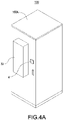
- FIG. 4A shows an appearance structure diagram of the cabinet with anti-condensation mechanism according to the present disclosure
- FIG. 4B which shows a cabinet configuration diagram of the cabinet with anti-condensation mechanism according to the present disclosure
- FIG. 4C shows an appearance structure diagram of opening a cabinet door of the cabinet with anti-condensation mechanism according to the present disclosure, and also refer to FIG. 1 to FIG. 3 .
- the cabinet 100 includes the cabinet body 100A, and the air conditioning module 22 and the switch 4 are disposed on one of the surfaces of the cabinet 100.
- the air conditioning module 22 is used to adjust the cabinet-inside temperature Ti in the accommodation space 100C of the cabinet 100.
- the switch 4 is used for the user to press to generate a trigger.
- the locking module 3 i.e., the electromagnetic lock
- the controller 16 are disposed on the cabinet door 100B, and the sensing modules (12, 14), the heating module 24, and the battery module 6 are disposed in the accommodation space 100C.
- FIG. 4A to FIG. 4C are different configuration modes of the cabinet 100, and the actual configuration mode may be varied according to actual requirements.
Landscapes
- Engineering & Computer Science (AREA)
- Chemical & Material Sciences (AREA)
- Chemical Kinetics & Catalysis (AREA)
- Electrochemistry (AREA)
- General Chemical & Material Sciences (AREA)
- Manufacturing & Machinery (AREA)
- Physics & Mathematics (AREA)
- Combustion & Propulsion (AREA)
- Mechanical Engineering (AREA)
- Thermal Sciences (AREA)
- General Engineering & Computer Science (AREA)
- Microelectronics & Electronic Packaging (AREA)
- Cooling Or The Like Of Electrical Apparatus (AREA)
- Casings For Electric Apparatus (AREA)
- Patch Boards (AREA)
- Charge And Discharge Circuits For Batteries Or The Like (AREA)
- Toilet Supplies (AREA)
Abstract
Description
- The present disclosure relates to a cabinet and a method of controlling the same, and more particularly to a cabinet with anti-condensation mechanism and an anti-condensation control method.
- The statements in this section merely provide background information related to the present disclosure and do not necessarily constitute prior art.
- Nowadays, the demand for electric energy is becoming more and more extensive, so more and more products need to use battery storage cabinets as backup and energy storage devices. In particular, battery storage cabinets with lithium batteries are the most widely used. As the application demand of lithium batteries increases, the operational safety of lithium batteries is gradually being valued. It can be seen from more and more domestic and foreign fire case analysis reports that most of the fires are caused by improper control of the ambient temperature and humidity in the lithium battery energy storage cabinet, which causes condensation and high-voltage arc short-circuit abnormality.
- In conventional technology, in order to prolong the service life of the battery and reduce the decline, outdoor battery cabinets will use air-conditioning for cooling to maintain the cabinet-inside temperature in the battery cabinet at 20-30 degrees Celsius. At this condition, if the cabinet-outside temperature is higher than the cabinet-inside temperature and the humidity is high, once the cabinet door is opened and hot and humid air enters the cabinet, condensation will occur on the surface of the internal parts and reduce the insulation, and therefore it will increase the possibility of fire in the lithium battery energy storage cabinet.
- In order to solve the above-mentioned problems, the present disclosure provides a cabinet with anti-condensation mechanism to control opening and closing a cabinet door of the cabinet. The cabinet includes a control module, a temperature control module, and a locking module. The control module senses a cabinet-inside temperature inside the cabinet, and senses a cabinet-outside temperature and a cabinet-outside humidity outside the cabinet to generate a dew-point threshold value. The temperature control module is coupled to the control module and adjusts the cabinet-inside temperature. The locking module is coupled to the control module and the cabinet door and locks the cabinet door or unlocks the cabinet door. The control module controls the locking module according to the cabinet-inside temperature and the dew-point threshold value, and controls the temperature control module to adjust the cabinet-inside temperature to be greater than or equal to the dew-point threshold value when the control module receives a trigger signal.
- In order to solve the above-mentioned problems, the present disclosure provides an anti-condensation control method of a cabinet. The method controls opening and closing a cabinet door of the cabinet. The method includes steps of: sensing a cabinet-inside temperature of the cabinet, and sensing a cabinet-outside temperature and a cabinet-outside humidity of the cabinet to generate a dew-point threshold value, determining whether the cabinet-inside temperature is greater than or equal to the dew-point threshold value, locking the cabinet door when determining that the cabinet-inside temperature is less than the dew-point threshold value, and adjusting the cabinet-inside temperature to be greater than or equal to the dew-point threshold value according to a trigger signal, and unlocking the cabinet door.
- The main purpose and effect of the present disclosure is to prevent the cabinet door from being opened when there is a high risk of condensation in the cabinet through the mutual control and linkage of the temperature and humidity sensing modules, the temperature control module, and the locking module inside and outside the cabinet, thereby effectively avoiding the occurrence of condensation and short circuit of electrical devices in the accommodation space.
- It is to be understood that both the foregoing general description and the following detailed description are exemplary, and are intended to provide further explanation of the present disclosure as claimed. Other advantages and features of the present disclosure will be apparent from the following description, drawings, and claims.
- The present disclosure can be more fully understood by reading the following detailed description of the embodiment, with reference made to the accompanying drawing as follows:
-
FIG. 1 is a block diagram of a cabinet with anti-condensation mechanism according to the present disclosure. -
FIG. 2 is a schematic table of a dew-point temperature corresponding to temperature and humidity of the cabinet with anti-condensation mechanism according to the present disclosure. -
FIG. 3 is a flowchart of an anti-condensation control method according to the present disclosure. -
FIG. 4A is an appearance structure diagram of the cabinet with anti-condensation mechanism according to the present disclosure. -
FIG. 4B is a cabinet configuration diagram of the cabinet with anti-condensation mechanism according to the present disclosure. -
FIG. 4C is an appearance structure diagram of opening a cabinet door of the cabinet with anti-condensation mechanism according to the present disclosure. - Reference will now be made to the drawing figures to describe the present disclosure in detail. It will be understood that the drawing figures and exemplified embodiments of present disclosure are not limited to the details thereof.
- Please refer to
FIG. 1 , which shows a block diagram of a cabinet with anti-condensation mechanism according to the present disclosure. Thecabinet 100 is usually installed in an open place such as outdoors, and is used to adjust the temperature in the cabinet 100 (hereinafter referred to as a cabinet-inside temperature). Thecabinet 100 includes acabinet body 100A and acabinet door 100B. Thecabinet body 100A and thecabinet door 100B form anaccommodation space 100C. Thecabinet 100 further includes a control module 1, atemperature control module 2, and alocking module 3. The control module 1 includes a cabinet-outside sensing module 12, a cabinet-insidesensing module 14, and acontroller 16. The cabinet-outside sensing module 12 is preferably disposed on an outer surface of thecabinet 100, and the cabinet-outside sensing module 12 includes a termperature sensor and a humidity sensor for sensing temperature and humidity. The cabinet-outsidesensing module 12 is used to sense a cabinet-outside temperature To and a cabinet-inside temperature Ho to generate a cabinet-outside temperature humidity signal Sth according to the cabinet-outside temperature To and the cabinet-inside temperature Ho. The cabinet-insidesensing module 14 is preferably disposed in theaccommodation space 100C, and the cabinet-insidesensing module 14 includes a temperature sensor for sensing a cabinet-inside temperature Ti to generate a cabinet-inside temperature signal St. Thetemperature control module 2 is preferably in theaccommodation space 100C for adjusting the cabinet-inside temperature Ti. Thelocking module 3 is coupled to thecontroller 16 and thecabinet door 100B for locking or unlocking thecabinet door 100B. In particular, thelocking module 3 may be disposed inside or outside theaccommodation space 100C according to actual needs, and thelocking module 3 may be, for example but not limited to, an electromagnetic lock, a central control lock, a controllable mechanical lock, or so on. - Specifically, the
temperature control module 2 includes anair conditioning module 22 and aheating module 24, and theair conditioning module 22 and theheating module 24 are coupled to thecontroller 16. Theair conditioning module 22 is used to adjust the cabinet-inside temperature Ti, and theheating module 24 is used to increase the cabinet-inside temperature Ti. In particular, theair conditioning module 22 may be a device for adjusting the ambient temperature such as an air conditioner, a fan, or so on. Theheating module 24 may be a heating device such as a resistance heater, a heating film, an electric heater, or so on. Thecontroller 16 is preferably disposed in theaccommodation space 100C, and thecontroller 16 is coupled to the cabinet-outside sensing module 12, the cabinet-insidesensing module 14, thetemperature control module 2, and thelocking module 3. Thecontroller 16 is used to receive the cabinet-outside temperature humidity signal Sth and the cabinet-inside temperature signal St to realize the cabinet-outside temperature To, the cabinet-inside temperature Ho, and the cabinet-inside temperature Ti. Thecontroller 16 provides a temperature control signal Stc to thetemperature control module 2 to control thetemperature control module 2 to adjust the cabinet-inside temperature Ti. In addition, thecontroller 16 provides an open-close signal Ss to thelocking module 3 to control thelocking module 3 to lock or unlock thecabinet door 100B. Preferably, thelocking module 3 is an electromagnetic lock, and thecontroller 16 controls locking or unlocking thecabinet door 100B by whether controlling an excitation (single excitation or continuous excitation) of the electromagnetic lock. In particular, thecontroller 16 may be an analog-digital controller composed of circuits, a chip with a microcontroller controlled by written programs, or a microcircuit component. - The
cabinet 100 further aswitch 4, analert module 5, and abattery module 6. Theswitch 4 and thealert module 5 are coupled to thecontroller 16. Theswitch 4 may be a touch switch, a DIP switch, a remote-control switch, a touch screen, or other devices capable of generating a trigger by a trigger operation, i.e., by an operation of triggering theswitch 4, and theswitch 4 is preferably disposed on an outer surface of thecabinet 100. Thealert module 5 may be a visual, auditory, or tactile alert device such as a buzzer, an alert light, a display panel, a vibrator, or so on, and thealert module 5 is preferably disposed on an outer surface of thecabinet 100. Theswitch 4 generates a trigger signal Str according to the trigger operation, and provides the trigger signal Str to thecontroller 16. When thecontroller 16 provides the open-close signal Ss to lock or unlock thecabinet door 100B, thecontroller 16 also provides a locking signal Sl (when thecabinet door 100B is locked) and an unlocking signal Sd (when thecabinet door 100B is unlocked) to thealert module 5 so that thealert module 5 respectively generates a (visual, auditory, or tactile) locking alert Wl and an (visual, auditory, or tactile) unlocking alert Wd. - The
battery module 6 is disposed in theaccommodation space 100C for receiving or delivering electricity power from or to anexternal system 200. Specifically, thecabinet 100 of the present disclosure is provided to control the temperature of the internal electronic equipment (such as but not limited to conversion devices, communication equipment, etc.), and avoid condensation in the cabinet due to improper humidity and temperature control, resulting in poor insulation and short-circuited danger of internal electronic equipment. Therefore, thecabinet 100 is particularly suitable for occasions where thebattery module 6 is arranged outdoors for receiving or delivering electricity power. In particular, thebattery module 6 may be, for example but not limited to, a storage battery, a lithium battery, and other devices that have a large amount of power storage. In order to prolong the service life and reduce the deterioration ofmost battery modules 6, thecabinet 100 uses theair conditioning module 22 for cooling to maintain the cabinet-inside temperature Ti within the predetermined temperature range. In particular, the predetermined temperature range (for example but not limited to 20-30 degrees Celsius) is usually constituted by an upper limit value and a lower limit value of an optimal operation ambient temperature (for example but not limited to 25 degrees Celsius) of thebattery module 6. However, when the cabinet-outside temperature To and the cabinet-outside humidity Ho of thecabinet 100 are higher than the cabinet-inside temperature Ti, once thecabinet door 100B is opened and the hot and humid air enters thecabinet 100, condensation will be generated on the surface of the internal components, resulting in insulation reduction. - Therefore, the main purpose and effect of the present disclosure is: the temperature and humidity sensing modules (12, 14) inside and outside the
cabinet 100 can be controlled and linked with theair conditioning module 22, theheating module 24, and thelocking module 3 to prevent thecabinet door 100B from being opened when there is a high risk of condensation in thecabinet 100, thereby effectively avoiding the occurrence of condensation and short circuit of the electric devices in theaccommodation space 100C. In particular, in some special conditions (for example but not limited to the limited internal space of the cabinet 100), the control module 1, thetemperature control module 2, thelocking module 3, and thealert module 5 may be arranged inside or outside theaccommodation space 100C according to actual needs, and the specific configuration positions of the control module 1, thetemperature control module 2, thelocking module 3, and thealert module 5 are not limited. Moreover, in one embodiment, the signal transmission may be wired or wireless transmission (indicated by the dotted lines). When the wireless transmission is used, each module may include a transmission unit (not shown) for sending and receiving signals so that each module may be configured more flexibly. - Please refer to
FIG. 2 , which shows a schematic table of a dew-point temperature corresponding to temperature and humicity of the cabinet with anti-condensation mechanism according to the present disclosure, and also refer toFIG. 1 . The cause of condensation is directly related to the relative humidity and the present dew-point temperature. The dew-point temperature refers to a temperature at which the gaseous water contained in the air reaches saturation and condenses into liquid water under a fixed pressure. When the relative humidity and actual temperature are known, the dew-point temperature may be approximated by the following formulas:

- In which, To is the cabinet-outside temperature, Td is the dew-point temperature (in Celsius), Ho is the cabinet-outside humidity (expressed as a percentage of relative humidity), In is the natural logarithm, constant a is 17.27, and constant b is 237.7. Therefore, the dew-point temperature table shown in
FIG. 2 can be established. The above-mentioned formula 1 andformula 2 can be written in thecontroller 16, and the dew-point temperature (i.e., the dew-point threshold value) can be calculated by the sensed cabinet-outside temperature To and the sensed cabinet-outside humidity Ho. Alternatively, the dew-point temperature table shown inFIG. 2 can be recorded in thecontroller 16, and the dew-point threshold value can be acquired by looking up the dew-point temperature table through the sensed cabinet-outside temperature To and the sensed cabinet-outside humidity Ho. - The
controller 16 senses the cabinet-outside temperature To and the cabinet-outside humidity Ho to generate the dew-point threshold value, and determines whether a risk of condensation will occur according to the cabinet-inside temperature Ti and the dew-point threshold value. In particular, the action (operation) of sensing the cabinet-outside temperature To and the cabinet-outside humidity Ho to generate the dew-point threshold value can be performed at any time. When there is no risk of condensation (that is, the cabinet-inside temperature Ti is greater than or equal to the dew-point threshold value), thecontroller 16 provides the open-close signal Ss to control thelocking module 3 to unlock thecabinet door 100B. At this condition, thecontroller 16 controls theair conditioning module 22 through the temperature control signal Stc to maintain the cabinet-inside temperature Ti at the predetermined temperature range (for example but not limited to 30 degrees Celsius). Thecontroller 16 also provides the open-close signal Ss to continuously control thelocking module 3 to lock thecabinet door 100B to prevent thecabinet door 100B from opening accidentally without alerting. Therefore, when thecontroller 16 receives the trigger signal Str, thecabinet door 100B is unlocked by thelocking module 3 to provide the unlocking signal Sd to control thealert module 5 to provide the unlocking alert Wd. - When the
controller 16 determines that the risk of condensation will occur (that is, the cabinet-inside temperature Ti is less than the dew-point threshold value), thecontroller 16 provides the open-close signal Ss to control thelocking module 3 to lock thecabinet door 100B. Afterward, when thecontroller 16 receives the trigger signal Str, thecontroller 16 provides the temperature control signal Stc to control theheating module 24 to increase the cabinet-inside temperature Ti from the predetermined temperature range to be greater than or equal to the dew-point threshold value. When thecontroller 16 receives the trigger signal Str, thecontroller 16 also provides the locking signal Sl to control thealert module 5 to provide the locking alert Wl. Therefore, the present state of thecabinet 100 can be clearly indicated. When the cabinet-inside temperature Ti is greater than or equal to the dew-point threshold value, thecontroller 16 provides the open-close signal Ss to control thelocking module 3 to unlock thecabinet door 100B. Thecabinet door 100B is unlocked by thelocking module 3 to provide the unlocking signal Sd to control thealert module 5 to provide the unlocking alert Wd. - Moreover, in order to prevent the cabinet-inside temperature Ti from the predetermined temperature range to be greater than or equal to the dew-point threshold value by the
heating module 24 however theair conditioning module 22 is not turned off to cause the cabinet-inside temperature Ti to rise (increase) too slowly, when thecontroller 16 receives the trigger signal Str, thecontroller 16 first disables theair conditioning module 22 to forcibly turn off theair conditioning module 22. Afterward, a loop related to theheating module 24 is connected by switching a relay (not shown) so as to start thecabinet 100 to perform a temperature recovery process of theaccommodation space 100C of thecabinet 100. - Please refer to
FIG. 3 , which shows a flowchart of an anti-condensation control method according to the present disclosure, and also refer toFIG. 1 to FIG. 2 . The anti-condensation control method is provided to control opening and closing thecabinet door 100B of thecabinet 100 to prevent thecabinet door 100B from being opened when there is a high risk of condensation in thecabinet 100, thereby effectively avoiding the occurrence of condensation and short circuit of the electric devices in theaccommodation space 100C. The control method mainly includes steps of: first, sensing a cabinet-inside temperature of the cabinet, and sensing a cabinet-outside temperature and a cabinet-outside humidity of the cabinet to generate a dew-point threshold value (S100). Preferably, thecontroller 16 of the control module 1 is used to sense the cabinet-outside temperature To and the cabinet-outside Ho to generate the dew-point threshold value, and determines whether a risk of condensation will occur according to the cabinet-inside temperature Ti and the dew-point threshold value. In particular, the action (operation) of sensing the cabinet-outside temperature To and the cabinet-outside humidity Ho to generate the dew-point threshold value can be performed at any time. - Afterward, determining whether the cabinet-inside temperature is greater than or equal to the dew-point threshold value (S120). Afterward, unlocking the cabinet door when determining that the cabinet-inside temperature is greater than or equal to the dew-point threshold value (S140). Preferably, when there is no risk of condensation (that is, the cabinet-inside temperature Ti is greater than or equal to the dew-point threshold value), the
controller 16 provides the open-close signal Ss to control thelocking module 3 to unlock thecabinet door 100B so that the user can open thecabinet door 100B. Afterward, locking the cabinet door when determining that the cabinet-inside temperature is less than the dew-point threshold value (S160). Preferably, when thecontroller 16 determines that the risk of condensation will occur (that is, the cabinet-inside temperature Ti is less than the dew-point threshold value), thecontroller 16 provides the open-close signal Ss to control thelocking module 3 to lock thecabinet door 100B. Afterward, adjusting the cabinet-inside temperature to be greater than or equal to the dew-point threshold value according to the trigger signal (S180). Preferably, when the controller 116 receives the trigger signal Str, thecontroller 16 provides the temperature control signal Stc to control theheating module 24 to increase the cabinet-inside temperature Ti from the predetermined temperature range to be greater than or equal to the dew-point threshold value since the cabinet-inside temperature Ti is less than the dew-point threshold value. Finally, returning to the step (S140). - In the step (S100), the above-mentioned formula 1 and
formula 2 can be written in thecontroller 16, and the dew-point temperature (i.e., the dew-point threshold value) can be calculated by the sensed cabinet-outside temperature To and the sensed cabinet-outside humidity Ho. Alternatively, the dew-point temperature table shown inFIG. 2 can be recorded in thecontroller 16, and the dew-point threshold value can be acquired by looking up the dew-point temperature table through the sensed cabinet-outside temperature To and the sensed cabinet-outside humidity Ho. In addition, in the step (S100), thecontroller 16 controls theair conditioning module 22 through the temperature control signal Stc to maintain the cabinet-inside temperature Ti at the predetermined temperature range. In particular, the predetermined temperature range (for example but not limited to 20-30 degrees Celsius) is usually constituted by an upper limit value and a lower limit value of an optimal operation ambient temperature (for example but not limited to 25 degrees Celsius) of an internal power device, such as abattery module 6. - In the step (S180), in order to prevent the cabinet-inside temperature Ti from the predetermined temperature range to be greater than or equal to the dew-point threshold value by the
heating module 24 however theair conditioning module 22 is not turned off to cause the cabinet-inside temperature Ti to rise (increase) too slowly, when thecontroller 16 receives the trigger signal Str, thecontroller 16 first disables theair conditioning module 22 to forcibly turn off theair conditioning module 22. - In the step (S140) to the step (S160), preferably, the
locking module 3 is an electromagnetic lock, and thecabinet door 100B is locked or unlocked by whether controlling an excitation of the electromagnetic lock. Moreover, in the step (S180) to the step (S140), when thecontroller 16 provides the open-close signal Ss to lock or unlock thecabinet door 100B, thecontroller 16 also provides a locking signal Sl (when thecabinet door 100B is locked) and an unlocking signal Sd (when thecabinet door 100B is unlocked) to thealert module 5 so that thealert module 5 respectively generates a (visual, auditory, or tactile) locking alert Wl and an (visual, auditory, or tactile) unlocking alert Wd. - Please refer to
FIG. 4A , which shows an appearance structure diagram of the cabinet with anti-condensation mechanism according to the present disclosure,FIG. 4B , which shows a cabinet configuration diagram of the cabinet with anti-condensation mechanism according to the present disclosure, andFIG. 4C , which shows an appearance structure diagram of opening a cabinet door of the cabinet with anti-condensation mechanism according to the present disclosure, and also refer toFIG. 1 to FIG. 3 . As shown inFIG. 4A , thecabinet 100 includes thecabinet body 100A, and theair conditioning module 22 and theswitch 4 are disposed on one of the surfaces of thecabinet 100. Theair conditioning module 22 is used to adjust the cabinet-inside temperature Ti in theaccommodation space 100C of thecabinet 100. Theswitch 4 is used for the user to press to generate a trigger. As shown inFIG. 4B andFIG. 4C , the locking module 3 (i.e., the electromagnetic lock) and thecontroller 16 are disposed on thecabinet door 100B, and the sensing modules (12, 14), theheating module 24, and thebattery module 6 are disposed in theaccommodation space 100C. In particular,FIG. 4A to FIG. 4C are different configuration modes of thecabinet 100, and the actual configuration mode may be varied according to actual requirements.
Claims (15)
- A cabinet (100) with anti-condensation mechanism configured to control opening and closing a cabinet door (100B) of the cabinet (100), characterized in that the cabinet (100) comprising:a control module (1), configured to sense a cabinet-inside temperature (Ti) inside the cabinet (100), and sense a cabinet-outside temperature (To) and a cabinet-outside humidity (Ho) outside the cabinet (100) to generate a dew-point threshold value,a temperature control module (2), coupled to the control module (1) and configured to adjust the cabinet-inside temperature (Ti), anda locking module (3), coupled to the control module (1) and the cabinet door (100B) and configured to lock the cabinet door (100B) or unlock the cabinet door (100B),wherein the control module (1) controls the locking module (3) according to the cabinet-inside temperature (Ti) and the dew-point threshold value, and controls the temperature control module (2) to adjust the cabinet-inside temperature (Ti) to be greater than or equal to the dew-point threshold value when the control module (1) receives a trigger signal.
- The cabinet (100) as claimed in claim 1, wherein when the control module (1) determines that the cabinet-inside temperature (Ti) is less than the dew-point threshold value, the control module (1) controls the locking module (3) to lock the cabinet door (100B).
- The cabinet (100) as claimed in claim 1, wherein when the control module (1) receives the trigger signal (Str) and determines that the cabinet-inside temperature (Ti) is greater than or equal to the dew-point threshold value, the control module (1) controls the locking module (3) to unlock the cabinet door (100B).
- The cabinet (100) as claimed in claim 1, wherein the control module (1) comprises:a cabinet-outside sensing module (12), configured to sense the cabinet-outside temperature (To) and the cabinet-outside humidity (Ho) to generate a cabinet-outside temperature humidity signal (Sth),a cabinet-inside sensing module (14), configured to sense the cabinet-inside temperature (Ti) and generate a cabinet-inside temperature signal (St), anda controller (16) coupled to the cabinet-outside sensing module (12), the cabinet-inside sensing module (14), the temperature control module (2), and the locking module (3),wherein the controller (16) provides a temperature control signal (Stc) and an open-close signal (Ss) to control the temperature control module (2) by the temperature control signal (Stc) and to control the locking module (3) by the open-close signal (Ss) according to the cabinet-outside temperature humidity signal (Sth), the cabinet-inside temperature signal (St), and the trigger signal (Str).
- The cabinet (100) as claimed in claim 4, wherein the controller (16) records a dew-point temperature table, and looks up the dew-point temperature table through the cabinet-outside temperature (To) and the cabinet-outside humidity (Ho) to acquire the dew-point threshold value.
- The cabinet (100) as claimed in claim 4, wherein the locking module (3) is an electromagnetic lock, and the control module (1) controls whether to excite the electromagnetic lock by the open-close signal (Ss) to lock or unlock the cabinet door (100B).
- The cabinet (100) as claimed in claim 1, wherein the temperature control module (2) comprises:an air conditioning module (22), coupled to the control module (1) and configured to adjust the cabinet-inside temperature (Ti), anda heating module (24), coupled to the control module (1) and configured to increase the cabinet-inside temperature (Ti),wherein the control module (1) controls the air conditioning module (22) to maintain the cabinet-inside temperature (Ti) at a predetermined temperature range, and controls the heating module (24) to increase the cabinet-inside temperature (Ti) from the predetermined temperature range to be greater than or equal to the dew-point threshold value according to the trigger signal (Str), and the control module (1) disables the air conditioning module (22) according to the trigger signal (Str).
- The cabinet (100) as claimed in claim 7, further comprising:a battery module (6), disposed inside the cabinet (100) and configured to receive or deliver an electricity power from or to an external system (200), andan alert module (5), coupled to the control module (1),wherein the predetermined temperature range is constituted by an upper limit value and a lower limit value of an optimal operation ambient temperature of the battery module (6),wherein the control module (1) controls the alert module (5) to provide an unlock alert (Wd) when the locking module (3) unlocks the cabinet door (100B),wherein the control module (1) controls the alert module (5) to provide a lock alert (Wl) when the locking module (3) locks the cabinet door (100B).
- The cabinet (100) as claimed in claim 1, further comprising:a switch (4), disposed on the cabinet (100) and coupled to the control module (1),wherein the switch (4) provides the trigger signal (Str) to the control module (1) according to a trigger operation.
- An anti-condensation control method of a cabinet (100), configured to control opening and closing a cabinet door (100B) of the cabinet (100), characterized in that the anti-condensation control method comprising steps of:sensing a cabinet-inside temperature (Ti) of the cabinet (100), and sensing a cabinet-outside temperature (To) and a cabinet-outside humidity (Ho) of the cabinet (100) to generate a dew-point threshold value,determining whether the cabinet-inside temperature (Ti) is greater than or equal to the dew-point threshold value,locking the cabinet door (100B) when determining that the cabinet-inside temperature (Ti) is less than the dew-point threshold value, and adjusting the cabinet-inside temperature (Ti) to be greater than or equal to the dew-point threshold value according to a trigger signal (Str), andunlocking the cabinet door (100B).
- The anti-condensation control method as claimed in claim 10, further comprising a step of:
unlocking the cabinet door (100B) when determining that the cabinet-inside temperature (Ti) is greater than or equal to the dew-point threshold value. - The anti-condensation control method as claimed in claim 10, further comprising a step of:
recording a dew-point temperature table, and acquiring the dew-point threshold value by looking up the dew-point temperature table through the cabinet-outside temperature (To) and the cabinet-outside humidity (Ho). - The anti-condensation control method as claimed in claim 10, further comprising a step of:
locking or unlocking the cabinet door (100B) by whether controlling an excitation of an electromagnetic lock. - The anti-condensation control method as claimed in claim 10, further comprising steps of:controlling an air conditioning module (22) to maintain the cabinet-inside temperature (Ti) at a predetermined temperature range,controlling a heating module (24) according to the trigger signal (Str) to increase the cabinet-inside temperature (Ti) from the predetermined temperature range to be greater than or equal to the dew-point threshold value, anddisabling the air conditioning module (22) according to the trigger signal (Str).
- The anti-condensation control method as claimed in claim 10, further comprising a step of:providing a lock alert (Wl) according to locking the cabinet door (100B), andproviding an unlock alert (Wd) according to unlocking the cabinet door (100B).
Applications Claiming Priority (1)
| Application Number | Priority Date | Filing Date | Title |
|---|---|---|---|
| TW110120637A TWI767743B (en) | 2021-06-07 | 2021-06-07 | Cabinet with anti-condensation mechanism and method of anti-condensation control the same |
Publications (3)
| Publication Number | Publication Date |
|---|---|
| EP4102629A1 true EP4102629A1 (en) | 2022-12-14 |
| EP4102629C0 EP4102629C0 (en) | 2025-05-21 |
| EP4102629B1 EP4102629B1 (en) | 2025-05-21 |
Family
ID=78087226
Family Applications (1)
| Application Number | Title | Priority Date | Filing Date |
|---|---|---|---|
| EP21202014.3A Active EP4102629B1 (en) | 2021-06-07 | 2021-10-11 | Cabinet with anti-condensation mechanism and anti-condensation control method |
Country Status (4)
| Country | Link |
|---|---|
| US (1) | US12044458B2 (en) |
| EP (1) | EP4102629B1 (en) |
| JP (1) | JP7278350B2 (en) |
| TW (1) | TWI767743B (en) |
Families Citing this family (3)
| Publication number | Priority date | Publication date | Assignee | Title |
|---|---|---|---|---|
| US20230335825A1 (en) * | 2022-04-18 | 2023-10-19 | Carrier Corporation | Systems and methods for battery energy system storage control |
| CN116263269A (en) * | 2022-12-16 | 2023-06-16 | 宁波惠康实业有限公司 | A method for preventing condensation of electrical components in an air conditioner in an electric cabin |
| CN121036296B (en) * | 2025-10-28 | 2026-04-03 | 洛阳龙羽集团有限公司 | A power supply strategy optimization method and ring main unit for condensation control |
Citations (3)
| Publication number | Priority date | Publication date | Assignee | Title |
|---|---|---|---|---|
| KR200330144Y1 (en) * | 2003-05-06 | 2003-10-17 | 정현 | Electronic Door Lock Having Moisture-proofing Apparatus |
| KR20180003978A (en) * | 2017-02-06 | 2018-01-10 | 한웅 | A self-diagnosis module for diagnosing whether or not the operation is correct within the power distribution panel itself and for alarming if the operation is inaccurate, and a switchboard |
| CN109193420A (en) * | 2018-09-11 | 2019-01-11 | 常州工学院 | One kind is for the anti-condensation system of cooling and its control method in outdoor ring main unit |
Family Cites Families (8)
| Publication number | Priority date | Publication date | Assignee | Title |
|---|---|---|---|---|
| US6936372B1 (en) * | 2002-08-15 | 2005-08-30 | Tyco Electronics Power Systems, Inc. | Environmental control system for use with a battery cabinet and method of operating a fan therein |
| US7728711B2 (en) * | 2006-03-29 | 2010-06-01 | S&S X-Ray Products, Inc | Remotely or locally actuated refrigerator lock with temperature and humidity detection |
| TWM408058U (en) * | 2010-12-31 | 2011-07-21 | Tairone Energy Saving Technology Co Ltd | Outdoor machine enclosure structure equips with temperature control system |
| JP6259419B2 (en) * | 2015-06-01 | 2018-01-10 | ファナック株式会社 | Laser device having a function for determining whether or not the door can be opened |
| JP2018073534A (en) * | 2016-10-26 | 2018-05-10 | パナソニックIpマネジメント株式会社 | Power storage device |
| CN207992851U (en) * | 2018-03-26 | 2018-10-19 | 江西锐天科创电气科技有限公司 | A kind of injection molding machine Special frequency converter |
| CN109556251A (en) * | 2018-11-12 | 2019-04-02 | 广东美的暖通设备有限公司 | Air conditioner and its control method, control device |
| CN112346498A (en) * | 2020-11-11 | 2021-02-09 | 石家庄通合电子科技股份有限公司 | Temperature control method, temperature control device and cabinet condensation removing equipment |
-
2021
- 2021-06-07 TW TW110120637A patent/TWI767743B/en active
- 2021-10-04 JP JP2021163247A patent/JP7278350B2/en active Active
- 2021-10-11 EP EP21202014.3A patent/EP4102629B1/en active Active
- 2021-11-04 US US17/518,857 patent/US12044458B2/en active Active
Patent Citations (3)
| Publication number | Priority date | Publication date | Assignee | Title |
|---|---|---|---|---|
| KR200330144Y1 (en) * | 2003-05-06 | 2003-10-17 | 정현 | Electronic Door Lock Having Moisture-proofing Apparatus |
| KR20180003978A (en) * | 2017-02-06 | 2018-01-10 | 한웅 | A self-diagnosis module for diagnosing whether or not the operation is correct within the power distribution panel itself and for alarming if the operation is inaccurate, and a switchboard |
| CN109193420A (en) * | 2018-09-11 | 2019-01-11 | 常州工学院 | One kind is for the anti-condensation system of cooling and its control method in outdoor ring main unit |
Also Published As
| Publication number | Publication date |
|---|---|
| TWI767743B (en) | 2022-06-11 |
| JP2022187459A (en) | 2022-12-19 |
| TW202248578A (en) | 2022-12-16 |
| JP7278350B2 (en) | 2023-05-19 |
| US20220390166A1 (en) | 2022-12-08 |
| EP4102629C0 (en) | 2025-05-21 |
| US12044458B2 (en) | 2024-07-23 |
| EP4102629B1 (en) | 2025-05-21 |
Similar Documents
| Publication | Publication Date | Title |
|---|---|---|
| EP4102629B1 (en) | Cabinet with anti-condensation mechanism and anti-condensation control method | |
| CN212276243U (en) | Power distribution cabinet environment monitoring system with active safety equipment | |
| CN107708373A (en) | A kind of cabinet-type data center and its control method | |
| CN103605386A (en) | Electric appliance control cabinet capable of automatic heat dissipation | |
| CN116827709A (en) | A control method, device, electronic device and storage medium | |
| CN207067703U (en) | Cabinet-type data center cabinet door, the control device of skylight | |
| CN205004669U (en) | Intelligent metal sealed switch equipment | |
| CN205407512U (en) | Motor heating device | |
| CN210781125U (en) | Anti-electricity-theft device for transformer | |
| CN214586604U (en) | Insulating tool storage monitoring devices | |
| CN216741161U (en) | A electric door closer for preventing fire door control | |
| RU2710209C2 (en) | Power and control device intended for medium-voltage equipment, and medium-voltage switching device | |
| CN214475194U (en) | Transformer substation's screen cabinet blocking device | |
| CN206041568U (en) | Charging cabinet | |
| WO2019200724A1 (en) | Apparatus, system and method for controlling energization and de-energization of solar module | |
| CN222692137U (en) | Heat dissipation protection device and grid-connected test platform | |
| CN116207850A (en) | Intelligent wireless power supply control system of refrigerator with screen on door | |
| CN113937895A (en) | Mini electronic box | |
| CN220137320U (en) | SF6 density monitoring device | |
| CN208905259U (en) | A kind of novel electric appliance control cabinet | |
| CN216846592U (en) | Oven temperature safety monitoring device | |
| CN207938480U (en) | A kind of passive blocking device of 10kV open lockings incoming line cabinet | |
| CN209978958U (en) | Door opening and closing alarm system of capacitor box and distribution box | |
| WO2003021163A1 (en) | System and method for freight refrigeration power control | |
| CN218888161U (en) | Charging cabinet |
Legal Events
| Date | Code | Title | Description |
|---|---|---|---|
| PUAI | Public reference made under article 153(3) epc to a published international application that has entered the european phase |
Free format text: ORIGINAL CODE: 0009012 |
|
| STAA | Information on the status of an ep patent application or granted ep patent |
Free format text: STATUS: REQUEST FOR EXAMINATION WAS MADE |
|
| 17P | Request for examination filed |
Effective date: 20221027 |
|
| AK | Designated contracting states |
Kind code of ref document: A1 Designated state(s): AL AT BE BG CH CY CZ DE DK EE ES FI FR GB GR HR HU IE IS IT LI LT LU LV MC MK MT NL NO PL PT RO RS SE SI SK SM TR |
|
| GRAP | Despatch of communication of intention to grant a patent |
Free format text: ORIGINAL CODE: EPIDOSNIGR1 |
|
| STAA | Information on the status of an ep patent application or granted ep patent |
Free format text: STATUS: GRANT OF PATENT IS INTENDED |
|
| RIC1 | Information provided on ipc code assigned before grant |
Ipc: H01M 10/42 20060101ALN20241213BHEP Ipc: H01M 10/48 20060101ALI20241213BHEP Ipc: H01M 50/204 20210101AFI20241213BHEP |
|
| INTG | Intention to grant announced |
Effective date: 20250107 |
|
| RIC1 | Information provided on ipc code assigned before grant |
Ipc: H01M 10/42 20060101ALN20241220BHEP Ipc: H01M 10/48 20060101ALI20241220BHEP Ipc: H01M 50/204 20210101AFI20241220BHEP |
|
| GRAS | Grant fee paid |
Free format text: ORIGINAL CODE: EPIDOSNIGR3 |
|
| GRAA | (expected) grant |
Free format text: ORIGINAL CODE: 0009210 |
|
| STAA | Information on the status of an ep patent application or granted ep patent |
Free format text: STATUS: THE PATENT HAS BEEN GRANTED |
|
| AK | Designated contracting states |
Kind code of ref document: B1 Designated state(s): AL AT BE BG CH CY CZ DE DK EE ES FI FR GB GR HR HU IE IS IT LI LT LU LV MC MK MT NL NO PL PT RO RS SE SI SK SM TR |
|
| REG | Reference to a national code |
Ref country code: GB Ref legal event code: FG4D |
|
| REG | Reference to a national code |
Ref country code: CH Ref legal event code: EP |
|
| REG | Reference to a national code |
Ref country code: IE Ref legal event code: FG4D |
|
| U01 | Request for unitary effect filed |
Effective date: 20250521 |
|
| U07 | Unitary effect registered |
Designated state(s): AT BE BG DE DK EE FI FR IT LT LU LV MT NL PT RO SE SI Effective date: 20250526 |
|
| PG25 | Lapsed in a contracting state [announced via postgrant information from national office to epo] |
Ref country code: ES Free format text: LAPSE BECAUSE OF FAILURE TO SUBMIT A TRANSLATION OF THE DESCRIPTION OR TO PAY THE FEE WITHIN THE PRESCRIBED TIME-LIMIT Effective date: 20250521 |
|
| PG25 | Lapsed in a contracting state [announced via postgrant information from national office to epo] |
Ref country code: NO Free format text: LAPSE BECAUSE OF FAILURE TO SUBMIT A TRANSLATION OF THE DESCRIPTION OR TO PAY THE FEE WITHIN THE PRESCRIBED TIME-LIMIT Effective date: 20250821 Ref country code: GR Free format text: LAPSE BECAUSE OF FAILURE TO SUBMIT A TRANSLATION OF THE DESCRIPTION OR TO PAY THE FEE WITHIN THE PRESCRIBED TIME-LIMIT Effective date: 20250822 |
|
| PG25 | Lapsed in a contracting state [announced via postgrant information from national office to epo] |
Ref country code: PL Free format text: LAPSE BECAUSE OF FAILURE TO SUBMIT A TRANSLATION OF THE DESCRIPTION OR TO PAY THE FEE WITHIN THE PRESCRIBED TIME-LIMIT Effective date: 20250521 |
|
| U20 | Renewal fee for the european patent with unitary effect paid |
Year of fee payment: 5 Effective date: 20250909 |
|
| PG25 | Lapsed in a contracting state [announced via postgrant information from national office to epo] |
Ref country code: HR Free format text: LAPSE BECAUSE OF FAILURE TO SUBMIT A TRANSLATION OF THE DESCRIPTION OR TO PAY THE FEE WITHIN THE PRESCRIBED TIME-LIMIT Effective date: 20250521 |
|
| PG25 | Lapsed in a contracting state [announced via postgrant information from national office to epo] |
Ref country code: RS Free format text: LAPSE BECAUSE OF FAILURE TO SUBMIT A TRANSLATION OF THE DESCRIPTION OR TO PAY THE FEE WITHIN THE PRESCRIBED TIME-LIMIT Effective date: 20250821 |
|
| PG25 | Lapsed in a contracting state [announced via postgrant information from national office to epo] |
Ref country code: IS Free format text: LAPSE BECAUSE OF FAILURE TO SUBMIT A TRANSLATION OF THE DESCRIPTION OR TO PAY THE FEE WITHIN THE PRESCRIBED TIME-LIMIT Effective date: 20250921 |
|
| PG25 | Lapsed in a contracting state [announced via postgrant information from national office to epo] |
Ref country code: SM Free format text: LAPSE BECAUSE OF FAILURE TO SUBMIT A TRANSLATION OF THE DESCRIPTION OR TO PAY THE FEE WITHIN THE PRESCRIBED TIME-LIMIT Effective date: 20250521 |
|
| PG25 | Lapsed in a contracting state [announced via postgrant information from national office to epo] |
Ref country code: CZ Free format text: LAPSE BECAUSE OF FAILURE TO SUBMIT A TRANSLATION OF THE DESCRIPTION OR TO PAY THE FEE WITHIN THE PRESCRIBED TIME-LIMIT Effective date: 20250521 |
|
| PG25 | Lapsed in a contracting state [announced via postgrant information from national office to epo] |
Ref country code: SK Free format text: LAPSE BECAUSE OF FAILURE TO SUBMIT A TRANSLATION OF THE DESCRIPTION OR TO PAY THE FEE WITHIN THE PRESCRIBED TIME-LIMIT Effective date: 20250521 |
|
| PLBE | No opposition filed within time limit |
Free format text: ORIGINAL CODE: 0009261 |
|
| STAA | Information on the status of an ep patent application or granted ep patent |
Free format text: STATUS: NO OPPOSITION FILED WITHIN TIME LIMIT |
|
| REG | Reference to a national code |
Ref country code: CH Ref legal event code: L10 Free format text: ST27 STATUS EVENT CODE: U-0-0-L10-L00 (AS PROVIDED BY THE NATIONAL OFFICE) Effective date: 20260402 |
|
| 26N | No opposition filed |
Effective date: 20260224 |