EP4102559A1 - Power semiconductor module - Google Patents
Power semiconductor module Download PDFInfo
- Publication number
- EP4102559A1 EP4102559A1 EP21178802.1A EP21178802A EP4102559A1 EP 4102559 A1 EP4102559 A1 EP 4102559A1 EP 21178802 A EP21178802 A EP 21178802A EP 4102559 A1 EP4102559 A1 EP 4102559A1
- Authority
- EP
- European Patent Office
- Prior art keywords
- power semiconductor
- semiconductor module
- group
- module according
- gate
- Prior art date
- Legal status (The legal status is an assumption and is not a legal conclusion. Google has not performed a legal analysis and makes no representation as to the accuracy of the status listed.)
- Granted
Links
Images


Classifications
-
- H—ELECTRICITY
- H05—ELECTRIC TECHNIQUES NOT OTHERWISE PROVIDED FOR
- H05K—PRINTED CIRCUITS; CASINGS OR CONSTRUCTIONAL DETAILS OF ELECTRIC APPARATUS; MANUFACTURE OF ASSEMBLAGES OF ELECTRICAL COMPONENTS
- H05K1/00—Printed circuits
- H05K1/18—Printed circuits structurally associated with non-printed electric components
- H05K1/181—Printed circuits structurally associated with non-printed electric components associated with surface mounted components
-
- H—ELECTRICITY
- H05—ELECTRIC TECHNIQUES NOT OTHERWISE PROVIDED FOR
- H05K—PRINTED CIRCUITS; CASINGS OR CONSTRUCTIONAL DETAILS OF ELECTRIC APPARATUS; MANUFACTURE OF ASSEMBLAGES OF ELECTRICAL COMPONENTS
- H05K1/00—Printed circuits
- H05K1/18—Printed circuits structurally associated with non-printed electric components
- H05K1/189—Printed circuits structurally associated with non-printed electric components characterised by the use of flexible or folded printed circuits
-
- H—ELECTRICITY
- H10—SEMICONDUCTOR DEVICES; ELECTRIC SOLID-STATE DEVICES NOT OTHERWISE PROVIDED FOR
- H10W—GENERIC PACKAGES, INTERCONNECTIONS, CONNECTORS OR OTHER CONSTRUCTIONAL DETAILS OF DEVICES COVERED BY CLASS H10
- H10W44/00—Electrical arrangements for controlling or matching impedance
- H10W44/501—Inductive arrangements
-
- H—ELECTRICITY
- H10—SEMICONDUCTOR DEVICES; ELECTRIC SOLID-STATE DEVICES NOT OTHERWISE PROVIDED FOR
- H10W—GENERIC PACKAGES, INTERCONNECTIONS, CONNECTORS OR OTHER CONSTRUCTIONAL DETAILS OF DEVICES COVERED BY CLASS H10
- H10W70/00—Package substrates; Interposers; Redistribution layers [RDL]
- H10W70/60—Insulating or insulated package substrates; Interposers; Redistribution layers
- H10W70/611—Insulating or insulated package substrates; Interposers; Redistribution layers for connecting multiple chips together
-
- H—ELECTRICITY
- H10—SEMICONDUCTOR DEVICES; ELECTRIC SOLID-STATE DEVICES NOT OTHERWISE PROVIDED FOR
- H10W—GENERIC PACKAGES, INTERCONNECTIONS, CONNECTORS OR OTHER CONSTRUCTIONAL DETAILS OF DEVICES COVERED BY CLASS H10
- H10W70/00—Package substrates; Interposers; Redistribution layers [RDL]
- H10W70/60—Insulating or insulated package substrates; Interposers; Redistribution layers
- H10W70/62—Insulating or insulated package substrates; Interposers; Redistribution layers characterised by their interconnections
- H10W70/65—Shapes or dispositions of interconnections
-
- H—ELECTRICITY
- H10—SEMICONDUCTOR DEVICES; ELECTRIC SOLID-STATE DEVICES NOT OTHERWISE PROVIDED FOR
- H10W—GENERIC PACKAGES, INTERCONNECTIONS, CONNECTORS OR OTHER CONSTRUCTIONAL DETAILS OF DEVICES COVERED BY CLASS H10
- H10W70/00—Package substrates; Interposers; Redistribution layers [RDL]
- H10W70/60—Insulating or insulated package substrates; Interposers; Redistribution layers
- H10W70/67—Insulating or insulated package substrates; Interposers; Redistribution layers characterised by their insulating layers or insulating parts
- H10W70/68—Shapes or dispositions thereof
- H10W70/685—Shapes or dispositions thereof comprising multiple insulating layers
-
- H—ELECTRICITY
- H10—SEMICONDUCTOR DEVICES; ELECTRIC SOLID-STATE DEVICES NOT OTHERWISE PROVIDED FOR
- H10W—GENERIC PACKAGES, INTERCONNECTIONS, CONNECTORS OR OTHER CONSTRUCTIONAL DETAILS OF DEVICES COVERED BY CLASS H10
- H10W70/00—Package substrates; Interposers; Redistribution layers [RDL]
- H10W70/60—Insulating or insulated package substrates; Interposers; Redistribution layers
- H10W70/67—Insulating or insulated package substrates; Interposers; Redistribution layers characterised by their insulating layers or insulating parts
- H10W70/688—Flexible insulating substrates
-
- H—ELECTRICITY
- H10—SEMICONDUCTOR DEVICES; ELECTRIC SOLID-STATE DEVICES NOT OTHERWISE PROVIDED FOR
- H10W—GENERIC PACKAGES, INTERCONNECTIONS, CONNECTORS OR OTHER CONSTRUCTIONAL DETAILS OF DEVICES COVERED BY CLASS H10
- H10W90/00—Package configurations
-
- H—ELECTRICITY
- H10—SEMICONDUCTOR DEVICES; ELECTRIC SOLID-STATE DEVICES NOT OTHERWISE PROVIDED FOR
- H10W—GENERIC PACKAGES, INTERCONNECTIONS, CONNECTORS OR OTHER CONSTRUCTIONAL DETAILS OF DEVICES COVERED BY CLASS H10
- H10W90/00—Package configurations
- H10W90/401—Package configurations characterised by multiple insulating or insulated package substrates, interposers or RDLs
-
- H—ELECTRICITY
- H10—SEMICONDUCTOR DEVICES; ELECTRIC SOLID-STATE DEVICES NOT OTHERWISE PROVIDED FOR
- H10W—GENERIC PACKAGES, INTERCONNECTIONS, CONNECTORS OR OTHER CONSTRUCTIONAL DETAILS OF DEVICES COVERED BY CLASS H10
- H10W72/00—Interconnections or connectors in packages
- H10W72/50—Bond wires
-
- H—ELECTRICITY
- H10—SEMICONDUCTOR DEVICES; ELECTRIC SOLID-STATE DEVICES NOT OTHERWISE PROVIDED FOR
- H10W—GENERIC PACKAGES, INTERCONNECTIONS, CONNECTORS OR OTHER CONSTRUCTIONAL DETAILS OF DEVICES COVERED BY CLASS H10
- H10W72/00—Interconnections or connectors in packages
- H10W72/50—Bond wires
- H10W72/541—Dispositions of bond wires
- H10W72/547—Dispositions of multiple bond wires
- H10W72/5473—Dispositions of multiple bond wires multiple bond wires connected to a common bond pad
-
- H—ELECTRICITY
- H10—SEMICONDUCTOR DEVICES; ELECTRIC SOLID-STATE DEVICES NOT OTHERWISE PROVIDED FOR
- H10W—GENERIC PACKAGES, INTERCONNECTIONS, CONNECTORS OR OTHER CONSTRUCTIONAL DETAILS OF DEVICES COVERED BY CLASS H10
- H10W72/00—Interconnections or connectors in packages
- H10W72/851—Dispositions of multiple connectors or interconnections
- H10W72/874—On different surfaces
- H10W72/884—Die-attach connectors and bond wires
Definitions
- the present disclosure relates to a power semiconductor module with a plurality of semiconductor switches arranged in at least two groups, the semiconductor switches having a first terminal and a second terminal of a controlled path and a control terminal.
- a power semiconductor module is known in which several power semiconductor switches are connected together using separate substrate metallizations which are arranged in a stacked manner.
- the object is achieved by a power semiconductor module with a plurality of semiconductor switches arranged in at least two groups, the semiconductor switches having a first terminal and a second terminal of a controlled path and a control terminal, each group having a first group contact which is connected to the first terminals, a second group contact which is connected to the second terminals and a control group contact which is connected to the control terminals, an interconnection bridge for connecting the control group contacts and the first group contacts of the at least two groups, the interconnection bridge comprising a layer structure with a first conductive layer and a second conductive layer being separated by an insulating layer.
- Voltage applied between the control group contacts and between the first group contacts is used to control the state of the semiconductor devices, i.e. the voltage effects a switching of states between open and closed. Therefore, fast change of this voltage without critical oscillations is important for low-loss operation.
- the described embodiments have an improved gate connection. Because of the very close arrangement within the interconnection bridge where both conductive layers are separated only by a very thin insulating layer, a substantial reduction of the gate control loop inductance can be achieved compared to the conventional wire-bond connection between substrates.
- the physical reason for the reduced inductance is that for a very close arrangement of two conductors the inductive coupling significantly increases.
- a current flowing through a the gate connection layer of the interconnection bridge to the gate terminals of the switches of that group mainly charges capacities of the gate electrodes.
- Related currents flow in the other direction through the source connection layer of the interconnection bridge. Due to the anti-parallel direction of the currents and the mutual inductive coupling, a substantial reduction of the gate inductance can be effected.
- the proposed embodiment enables that also in power semiconductor modules in which a large number of semiconductor switches are connected in parallel and accordingly the lengths of the connection paths to the different groups of semiconductor switches are very different, the effect of the different lengths on the gate inductances of the different groups of semiconductor switches is attenuated and a better synchronization of the switching behavior and less oscillations can be achieved. This results in an improved switching behavior and less power loss during the switching period.
- resistors e.g. gate resistors located directly in the module, which are normally used to attenuate the oscillations between switches can be omitted or at least reduced. This additionally improves the switching behavior.
- resistors are omitted, a direct connection between a module gate contact and control terminals of the plurality of semiconductor switches can be implemented, which mean that there are no electronic elements in between.
- the layer structure is formed as a "normal" or flexible printed circuit board.
- both sides of a flexible insulating material are at least partly covered by a conductive material such as a metal.
- a conductive material such as a metal. Copper or aluminum or an alloy of copper and aluminum is advantageous as conductive material.
- the layer structure is formed by a ceramic substrate with a two side metallization. It is advantageous if the interconnection bridge has at least two feet on each side, the feet being connected to group contacts of both groups by soldering or welding or by an adhesive connection.
- Exemplarily MOSFETs or MISFETs or IGBTs are used as semiconductor switches in the embodiments described.
- the semiconductor switches may be based on Silicon or a wide bandgap material, exemplarily SiC or GaN.
- the present disclosure comprises an additional aspect of improvements of the gate connection, which is selectively increasing the inductance of certain connections within the module.
- a compensation structure is provided for shorter gate connection paths. While the total gate inductance is increased by this measure, the differences between the inductances of gate connection paths of different groups within the module can be reduced. This further reduces oscillations and accordingly improves the switching behavior.
- Compensation structures according to this aspect can be used in combination with the reduction of inductance as described above. This might become necessary or beneficial, because the physical possibilities to reduce the inductance are limited and a complete equalization cannot be achieved in all practical configurations. However, a combination of both aspects, i.e. reduction of the inductance of long connection paths and increase of inductance of short connection paths can lead to complete equalization or at least a substantial reduction of the differences of gate inductances.
- Figure 1 is a schematic view of a power module 1 comprising two groups 2 and 3 of semiconductor switches 4. Gate terminals 10 of semiconductor switches 4 are connected to a module gate contact 5. The length of the conduction paths between the module gate contact 5 and the gate terminals 10 of the semiconductor switches 4 depends on the geometric arrangement of the components within the module 1. For example, if more than two groups of semiconductor switches are provided, it can be difficult to achieve an equal length of the connection paths for each of the groups of semiconductor switches.
- the present disclosure it is not the aim to suppress oscillations but to avoid them from the beginning.
- the approach is not to minimize the total gate inductance of the power semiconductor module 1, but to equalize the gate inductances of different groups of semiconductor switches. While the switching capability of the power semiconductor module 1 also depends on the total inductance of the gate path, oscillations strongly depend on the difference of inductances and the path lengths of two different groups 2 and 3 of semiconductor switches 4.
- module stray inductance must be sufficiently low to avoid critical voltage overshoots, and inductance imbalance must be low to avoid oscillations between semiconductor switches.
- the inductance of the gate path of the first group 2 can be described as a shared inductance L_shared + interconnection inductance L_interconnection + inductance L1, while the inductance of the second gate path can be described as shared inductance L_shared + L2.
- the connection path to the first group 2 is longer than to the second group 3.
- a part of the gate path to the first group 2 is implemented with an interconnection bridge 6.
- the inductance of this part of the gate path can be reduced. In practice, a reduction of about 50% of the gate inductance of the gate path to the first group 2 can be achieved.
- the proposed features can be beneficial especially in design of complex high-power modules based on many silicon carbide or gallium nitride switches located on several substrates and connected in parallel.
- the concept of this disclosure can be implemented also in smaller power modules as shown in figure 1 .
- Figure 2 shows the effect of an interconnection bridge in such an embodiment.
- such two substrates would represent upper or lower side of the module.
- Another such two substrates, connected in parallel, would form the other switch of this half-bridge module.
- a resistor in the gate path can be at least reduced to a value of less than 2 ⁇ .
- Such resistors can be implemented as semiconductor resistors and do not require additional production steps.
- the disclosure has the advantage that resistors may be omitted to suppress oscillations or at least the implementation as substrate resistor.
- Figure 3 shows a more detailed view of two groups 2 and 3 of semiconductor switches 4.
- Semiconductor switches 4 are arranged on a metallization layer.
- a section 15 of the metallization layer is used as a drain connection.
- Another section of the metallization layer is separated to form a gate group contact 13, also referenced to as control group contact 13.
- Further parts of the metallization are separated as source group contact 14 which is also referenced to as first group contact 14. This applies to both substrates of groups 2 and 3.
- the gate terminals 10 of switches 4 are connected to a first side metallization 11 which appears in Figure 3 as top side metallization and from there to the gate group contact 13 as shown for the left group 2.
- the first side metallization can also be split in for example two parts connected via a resistor 24 and a bond wire as shown for the right group 3. This way the resistor 24 with a value of less than 2 Qis integrated in the gate path to attenuate oscillations.
- the source terminals of switches 4 are connected to a further metallization 16 which forms a source interconnection and from there to the first group contact 14.
- the interconnection bridge 6 is used for the connection between the substrates, that means also between the different groups of switches.
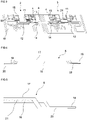
- Figure 4 shows a more detailed view of the interconnection bridge 6. It comprises two conductive layers 17 and 18. While the layer 18 is used as gate connection, layer 17 is used as source connection. Both layers are separated by an insulating layer which is not shown in this figure. On both sides of the interconnection bridge 6, feet 19 for the gate connection and feet 20 for the source connection are provided. These feet are connected to the control group contacts 13 and the first group contacts 14, for example, by welding or sintering or soldering or an adhesive.
- Figure 5 shows an even more detailed view of the interconnection bridge 6.
- the conductive layers 17 and 18 are separated by an insulating layer 21.
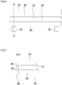
- the interconnection bridge comprises a stacked sequence of layers with an insulating and protecting layer 25, followed by a first metallization 26 for a first potential, a thin insulating layer 27, a second metallization 28 for a second potential and a second insulating and protecting layer 29.
- layers 25 and 26 and also layers 29 and 28 are provided as PCB.
- terminals 30 and 36 are arranged which are used for electrical connection of both metallizations, i.e. the first metallization 26 and the second metallization 28.
- vias can be used to access the metallizations 26 and 28 from the terminal side of the second insulating and protecting layer 29.
- Figure 7 shows a cross-section of the embodiment of Figure 7 .
- the terminals 30 and 36 for both potentials which can relate to the gate and source connection, are connected by vias to the first metallization 26 and the second metallization 28, respectively.
- the mechanical stability is increased. This can be beneficial for very long interconnection bridges and additionally opens the possibility to reduce the thickness of the insulating layer to a minimum because it does not have to provide a mechanical function for mechanically stabilizing the interconnection bridge.
- Another possibility for mechanically stabilizing the interconnection bridge is to use a glue somewhere between the terminals to support the bridge. This can be implemented for example in connection with all embodiments of this disclosure.
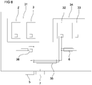
- FIG. 8 shows a further embodiment of this disclosure.
- groups 2 and 3 of semiconductor switches are integrated within a submodule 31.
- Two additional groups of semiconductor switches 32 and 33 are integrated within a second submodule 34.
- Each of the submodules 31 and 34 comprises a connection between the groups via an interconnection bridge 6 as described in the previous figures.
- an interconnection bridge 35 is used which is formed similar to the interconnection bridge 6 for the intergroup connection within each submodule 31 and 34.
- interconnection bridge 35 cannot fully equalize the differences of gate inductances of the gate paths to submodules 31 and 34. Therefore, an additional compensation structure 36 is provided according to the second aspect of this disclosure as described above.
- the compensation structure effects an increase of the inductance of the gate connection path to the switches of the first submodule 31. Both, the decrease of inductance by interconnection bridge 35 and increase of inductance by compensation structure 36 contributes to more equal inductances in the gate connection paths of both submodules 31 and 34.
- Figures 9 to 12 show possibilities which can be easily implemented.
- Figure 9 shows a meander like structure in which the connection between contact point 38 and contact point 39 is increased by the meander structure.
- islands 40 are formed in a metallization 22 of a substrate 23 and are connected by bond wires 41. Also this way the current path between connection points 38 and 39 is extended.
- the compensation structure can also be implemented in the metallization 11.
Landscapes
- Engineering & Computer Science (AREA)
- Microelectronics & Electronic Packaging (AREA)
- Power Conversion In General (AREA)
- Physics & Mathematics (AREA)
- Geometry (AREA)
Abstract
Description
- The present disclosure relates to a power semiconductor module with a plurality of semiconductor switches arranged in at least two groups, the semiconductor switches having a first terminal and a second terminal of a controlled path and a control terminal. From
EP 3113223 A1 a power semiconductor module is known in which several power semiconductor switches are connected together using separate substrate metallizations which are arranged in a stacked manner. - To obtain lower switching losses of a power module, it is an option to use wide-band-gap semiconductors which have in principle a fast switching behavior. However, the use of fast switching semiconductors raises new challenges to the design of modules. Additionally, the area of a typical wide-band-gap semiconductor device is considerably smaller than the area of a Si-device today; therefore, many more of them have to be connected in parallel to achieve targeted current rating.
- It is an object to provide a power semiconductor module which is based on wide-band-gap semiconductors and comprises many semiconductor switches connected in parallel and which has a fast switching behavior.
- According to an embodiment, the object is achieved by a power semiconductor module with a plurality of semiconductor switches arranged in at least two groups, the semiconductor switches having a first terminal and a second terminal of a controlled path and a control terminal, each group having a first group contact which is connected to the first terminals, a second group contact which is connected to the second terminals and a control group contact which is connected to the control terminals, an interconnection bridge for connecting the control group contacts and the first group contacts of the at least two groups, the interconnection bridge comprising a layer structure with a first conductive layer and a second conductive layer being separated by an insulating layer.
- Voltage applied between the control group contacts and between the first group contacts is used to control the state of the semiconductor devices, i.e. the voltage effects a switching of states between open and closed. Therefore, fast change of this voltage without critical oscillations is important for low-loss operation. The described embodiments have an improved gate connection. Because of the very close arrangement within the interconnection bridge where both conductive layers are separated only by a very thin insulating layer, a substantial reduction of the gate control loop inductance can be achieved compared to the conventional wire-bond connection between substrates.
- The physical reason for the reduced inductance is that for a very close arrangement of two conductors the inductive coupling significantly increases. A current flowing through a the gate connection layer of the interconnection bridge to the gate terminals of the switches of that group mainly charges capacities of the gate electrodes. Related currents flow in the other direction through the source connection layer of the interconnection bridge. Due to the anti-parallel direction of the currents and the mutual inductive coupling, a substantial reduction of the gate inductance can be effected.
- The proposed embodiment enables that also in power semiconductor modules in which a large number of semiconductor switches are connected in parallel and accordingly the lengths of the connection paths to the different groups of semiconductor switches are very different, the effect of the different lengths on the gate inductances of the different groups of semiconductor switches is attenuated and a better synchronization of the switching behavior and less oscillations can be achieved. This results in an improved switching behavior and less power loss during the switching period.
- It is a further advantage of the proposed embodiment that resistors, e.g. gate resistors located directly in the module, which are normally used to attenuate the oscillations between switches can be omitted or at least reduced. This additionally improves the switching behavior. In case that resistors are omitted, a direct connection between a module gate contact and control terminals of the plurality of semiconductor switches can be implemented, which mean that there are no electronic elements in between.
- With a sufficient reduction of oscillations, it is at least possible to replace thick film resistors by easily available semiconductor resistors which facilitates production of the module and reduces production costs.
- According to a more detailed embodiment the layer structure is formed as a "normal" or flexible printed circuit board. In such an embodiment, both sides of a flexible insulating material are at least partly covered by a conductive material such as a metal. Copper or aluminum or an alloy of copper and aluminum is advantageous as conductive material.
- According to another embodiment, the layer structure is formed by a ceramic substrate with a two side metallization. It is advantageous if the interconnection bridge has at least two feet on each side, the feet being connected to group contacts of both groups by soldering or welding or by an adhesive connection. Exemplarily MOSFETs or MISFETs or IGBTs are used as semiconductor switches in the embodiments described. The semiconductor switches may be based on Silicon or a wide bandgap material, exemplarily SiC or GaN.
- The present disclosure comprises an additional aspect of improvements of the gate connection, which is selectively increasing the inductance of certain connections within the module. According to this aspect, a compensation structure is provided for shorter gate connection paths. While the total gate inductance is increased by this measure, the differences between the inductances of gate connection paths of different groups within the module can be reduced. This further reduces oscillations and accordingly improves the switching behavior. Compensation structures according to this aspect can be used in combination with the reduction of inductance as described above. This might become necessary or beneficial, because the physical possibilities to reduce the inductance are limited and a complete equalization cannot be achieved in all practical configurations. However, a combination of both aspects, i.e. reduction of the inductance of long connection paths and increase of inductance of short connection paths can lead to complete equalization or at least a substantial reduction of the differences of gate inductances.
- Every feature described with respect to one of the aspects is also disclosed herein with respect to the other aspect, even if the respective feature is not explicitly mentioned in the context of the specific aspect.
- The accompanying figures are included to provide a further understanding. In the figures, elements of the same structure and/or functionality may be referenced by the same reference signs. It is to be understood that the embodiments shown in the figures are illustrative for presentations and are not necessarily drawn to scale.
-
Figure 1 is a schematic view of a first embodiment of a power module, -
Figure 2 is a diagram showing the effect of the first embodiment on the gate inductance, -
Figure 3 shows a more concrete view of the first embodiment, -
Figure 4 shows an embodiment of the interconnection bridge, -
Figure 5 shows a detail of the view offigure 4 , -
Figures 6 and 7 show another embodiment of an interconnection bridge with an increased mechanical stability, -
Figure 8 shows a second embodiment of a power module with an additional compensation structure, and -
Figures 9 to 12 show several design options for a compensation structure. -
Figure 1 is a schematic view of apower module 1 comprising twogroups semiconductor switches 4.Gate terminals 10 ofsemiconductor switches 4 are connected to amodule gate contact 5. The length of the conduction paths between themodule gate contact 5 and thegate terminals 10 of thesemiconductor switches 4 depends on the geometric arrangement of the components within themodule 1. For example, if more than two groups of semiconductor switches are provided, it can be difficult to achieve an equal length of the connection paths for each of the groups of semiconductor switches. - The unequal length of the gate connections became a problem because the use of wide-band-gap semiconductors such as silicon carbide, short: SiC, and gallium nitride, short GaN, became more popular to overcome limitations of silicon based power semiconductor devices. Exemplarily, wide bandgap based devices such as silicon carbide and gallium nitride based devices are attractive because of their fast switching capability resulting in low switching losses. However, when using a plurality of wide-band-gap semiconductors in a module, stronger oscillations within the modules were observed. To attenuate such oscillations, resistors were provided in the gate connection path. Often a resistor with 5 Ωis sufficient to suppress oscillations. However, for providing such a resistor the use of thick film technology was required which means that an additional production step was necessary. While it is possible this way to suppress oscillations, the initial advantage of wide-band-gap semiconductors which is the fast switching capability cannot be fully maintained.
- According to the present disclosure it is not the aim to suppress oscillations but to avoid them from the beginning. The approach is not to minimize the total gate inductance of the
power semiconductor module 1, but to equalize the gate inductances of different groups of semiconductor switches. While the switching capability of thepower semiconductor module 1 also depends on the total inductance of the gate path, oscillations strongly depend on the difference of inductances and the path lengths of twodifferent groups semiconductor switches 4. - In other words, to be able to switch fast, module stray inductance must be sufficiently low to avoid critical voltage overshoots, and inductance imbalance must be low to avoid oscillations between semiconductor switches.
- Turning to
Figure 1 , the inductance of the gate path of thefirst group 2 can be described as a shared inductance L_shared + interconnection inductance L_interconnection + inductance L1, while the inductance of the second gate path can be described as shared inductance L_shared + L2. As can be seen fromFigure 1 , the connection path to thefirst group 2 is longer than to thesecond group 3. According to this embodiment, a part of the gate path to thefirst group 2 is implemented with aninterconnection bridge 6. In connection with a very close sectional parallel arrangement of a source path from amodule source contact 7 to the source terminals ofswitches 4, the inductance of this part of the gate path can be reduced. In practice, a reduction of about 50% of the gate inductance of the gate path to thefirst group 2 can be achieved. - The proposed features can be beneficial especially in design of complex high-power modules based on many silicon carbide or gallium nitride switches located on several substrates and connected in parallel. However, the concept of this disclosure can be implemented also in smaller power modules as shown in
figure 1 . - It is a typical configuration of a
power semiconductor module 1 to connectmany semiconductor switches 4 in parallel in order to achieve the intended current density / current rating. This is true e.g. for silicon carbide and gallium nitride semiconductor switches, since the footprint of these switches is smaller compared to switches in Si-technology and accordingly more switches have to be connected in parallel in order to be able to switch a similar current. -
Figure 2 shows the effect of an interconnection bridge in such an embodiment. For example, it is possible togroup 10semiconductor switches 4 on one substrate of the module and another 10semiconductor switches 4 on another substrate of the module. 20semiconductor devices 4 located on both substrates are connected in parallel. In the case of half-bridge module configuration, such two substrates would represent upper or lower side of the module. Another such two substrates, connected in parallel, would form the other switch of this half-bridge module. - In the diagram of
Figure 2 the relative gate inductance in % of the maximum value is drawn for each switch located on any of two substrates connected in parallel. That means switches 1 to 10 belong to thefirst group 2 and switches 11 to 20 to thesecond group 3. As can be seen from the dashedline 8 showing the gate inductance for a power semiconductor module with conventional wire bonding, the maximum difference between gate inductances is 19%, while the difference within the group is only 6%. By using theinterconnection bridge 6, the inductance of the gate path of thefirst group 2 is reduced as can be seen from thesolid line 9. In an arrangement withinterconnection bridge 6, the maximum difference of gate inductances is only 12%. - As further effect, oscillations are reduced and thereby the switching speed can be increased. Measurements of the applicant have shown that the amplitude of oscillations of the gate voltage could be reduced to about 70%. Due to reduced oscillations, the power loss over the switching time could be reduced as well.
- Another positive effect of using the idea of this disclosure is that a resistor in the gate path can be at least reduced to a value of less than 2 Ω. Such resistors can be implemented as semiconductor resistors and do not require additional production steps.
- The disclosure has the advantage that resistors may be omitted to suppress oscillations or at least the implementation as substrate resistor.
-
Figure 3 shows a more detailed view of twogroups section 15 of the metallization layer is used as a drain connection. Another section of the metallization layer is separated to form agate group contact 13, also referenced to ascontrol group contact 13. Further parts of the metallization are separated assource group contact 14 which is also referenced to asfirst group contact 14. This applies to both substrates ofgroups - The
gate terminals 10 ofswitches 4 are connected to afirst side metallization 11 which appears inFigure 3 as top side metallization and from there to thegate group contact 13 as shown for theleft group 2. The first side metallization can also be split in for example two parts connected via aresistor 24 and a bond wire as shown for theright group 3. This way theresistor 24 with a value of less than 2 Qis integrated in the gate path to attenuate oscillations. - The source terminals of
switches 4 are connected to afurther metallization 16 which forms a source interconnection and from there to thefirst group contact 14. For the connection between the substrates, that means also between the different groups of switches, theinterconnection bridge 6 according to this disclosure is used. -
Figure 4 shows a more detailed view of theinterconnection bridge 6. It comprises twoconductive layers layer 18 is used as gate connection,layer 17 is used as source connection. Both layers are separated by an insulating layer which is not shown in this figure. On both sides of theinterconnection bridge 6,feet 19 for the gate connection andfeet 20 for the source connection are provided. These feet are connected to thecontrol group contacts 13 and thefirst group contacts 14, for example, by welding or sintering or soldering or an adhesive. -
Figure 5 shows an even more detailed view of theinterconnection bridge 6. As can be seen from this figure, theconductive layers layer 21. The closer theconductive layers - If the low thickness of layers results in unwanted low-mechanical stability of the bridge, an additional layer or layers can be added to increase this mechanical stability. An exemplary embodiment of an
interconnection bridge 6 with increased mechanical stability is shown inFigures 6 and 7 . According to this embodiment, the interconnection bridge comprises a stacked sequence of layers with an insulating and protectinglayer 25, followed by afirst metallization 26 for a first potential, a thin insulatinglayer 27, asecond metallization 28 for a second potential and a second insulating and protectinglayer 29. For example, layers 25 and 26 and also layers 29 and 28 are provided as PCB. - On the other side of the second insulating and protecting
layer 29terminals first metallization 26 and thesecond metallization 28. For that purpose, for example vias can be used to access themetallizations layer 29. -
Figure 7 shows a cross-section of the embodiment ofFigure 7 . Theterminals first metallization 26 and thesecond metallization 28, respectively. - Compared to the embodiment of
Figures 4 and 5 , the mechanical stability is increased. This can be beneficial for very long interconnection bridges and additionally opens the possibility to reduce the thickness of the insulating layer to a minimum because it does not have to provide a mechanical function for mechanically stabilizing the interconnection bridge. - Another possibility for mechanically stabilizing the interconnection bridge is to use a glue somewhere between the terminals to support the bridge. This can be implemented for example in connection with all embodiments of this disclosure.
-
Figure 8 shows a further embodiment of this disclosure. Here,groups submodule 31. Two additional groups of semiconductor switches 32 and 33 are integrated within asecond submodule 34. Each of thesubmodules interconnection bridge 6 as described in the previous figures. Also for the gate connection between thefirst submodule 31 and thesecond submodule 34 aninterconnection bridge 35 is used which is formed similar to theinterconnection bridge 6 for the intergroup connection within each submodule 31 and 34. However, according to this embodiment,interconnection bridge 35 cannot fully equalize the differences of gate inductances of the gate paths to submodules 31 and 34. Therefore, anadditional compensation structure 36 is provided according to the second aspect of this disclosure as described above. The compensation structure effects an increase of the inductance of the gate connection path to the switches of thefirst submodule 31. Both, the decrease of inductance byinterconnection bridge 35 and increase of inductance bycompensation structure 36 contributes to more equal inductances in the gate connection paths of bothsubmodules - It should be noted that for the technical effect of
interconnection bridges compensation structure 36 only the gate path has to be modified. - Regarding the implementation of compensation structures,
Figures 9 to 12 show possibilities which can be easily implemented.Figure 9 shows a meander like structure in which the connection betweencontact point 38 andcontact point 39 is increased by the meander structure. InFigure 10 ,islands 40 are formed in a metallization 22 of asubstrate 23 and are connected bybond wires 41. Also this way the current path between connection points 38 and 39 is extended. - In
Figure 11 a spiral like structure is used for a similar effect. - In
Figure 12 the structure ofFigure 11 is used, but the bond wires do not fully use the spiral like structure. This way theconfiguration structure 36 can be tuned to the specific needs of the individual groups which depend on the geometric arrangement within thepower semiconductor module 1. - With regard to the embodiment as shown in
Figure 3 , the compensation structure can also be implemented in themetallization 11. - The embodiments shown in
Figures 1 to 12 as stated represent exemplary embodiments of the improved arrangement of the power semiconductor module. Therefore, they do not constitute a complete list of all embodiments according to the improved arrangement. Actual arrangements may vary from the embodiments shown in terms of arrangements or devices. -
- 1 power semiconductor module
- 2 first group of semiconductor switches
- 3 second group of semiconductor switches
- 4 semiconductor switch
- 5 module gate contact
- 6 interconnection bridge
- 7 module source contact
- 8 gate inductance with conventional wire bonding
- 9 gate inductance with interconnection bridges
- 10 gate terminal
- 11 first side metallization
- 13 control group contact / gate group contact
- 14 first group contact / source group contact
- 15 second group contact / drain group contact
- 16 further metallization / source group contact
- 17 conductive layer
- 18 conductive layer
- 19 gate connection foot
- 20 source connection foot
- 21 insulating layer
- 23 substrate
- 24 resistor
- 25 first insulating and protecting layer
- 26 first bridge metallization
- 27 insulating layer
- 28 second bridge metallization
- 29 second insulating and protecting layer
- 30 first bridge terminals
- 31 first submodule
- 32 third group of semiconductor switches
- 33 forth group of semiconductor switches
- 34 second submodule
- 35 interconnection bridge
- 36
first bridge terminals 38 first connection point - 39 second connection point
- 40 metallization island
- 41 bond wire
Claims (14)
- A power semiconductor module (1) with
a plurality of semiconductor switches (4) arranged in at least two groups (2, 3, 32, 33), the semiconductor switches (4) having a first terminal and a second terminal of a controlled path and a control terminal (10),
each group (2, 3, 32, 33) having a first group contact (14) which is connected to the first terminals, a second group contact which is connected to the second terminals and a control group contact (13) which is connected to the control terminals (10),
an interconnection bridge (6, 35) for connecting the control group contacts (13) and the first group contacts (14) of the at least two groups (2, 3, 32, 33),
the interconnection bridge (6, 35) comprising a layer structure with a first conductive layer (17) and a second conductive layer (18) being separated by an insulating layer (21) . - The power semiconductor module according to claim 1,
characterized in that the layer structure is formed as a printed circuit board. - The power semiconductor module according to claim 2,
characterized in that the layer structure is formed as a flexible printed circuit board. - The power semiconductor module according to claim 1,
characterized in that the layer structure is formed by a ceramic substrate with a two-side metallization. - The power semiconductor module according to one of claims 1 to 4,
characterized in that the interconnection bridge (6, 35) comprises at least two feet (19, 20) on each side. - The power semiconductor module according to claim 5,
characterized in that the connection between the at least two feet (19, 20) of the interconnection bridge (6, 35) and the group contacts (13, 14) is a soldered connection, a welded connection or an sintered connection or an adhesive connection. - The power semiconductor module according to one of claims 1 to 6,
characterized in that the plurality of semiconductor switches (4) are at least one of: MOSFETs or IGBTs based on Si or a wide bandgap material. - The power semiconductor module according to one of claims 1 to 7,
characterized by a direct connection between a module gate contact (5) and control terminals (10) of the plurality of semiconductor switches. - The power semiconductor module according to one of claims 1 to 7,
characterized by a resistor (24) with less than 2 Qconnected between a module gate contact (5) and control terminals (10) of the plurality of semiconductor switches. - The power semiconductor module according to claim 9,
characterized in that the resistor (24) is a semiconductor resistor located on a metallization. - The power semiconductor module according to one of claims 1 to 10,
characterized in that a maximum difference in gate inductance within a group (2, 3, 32, 33) is 2 nH. - The power semiconductor module according to one of claims 1 to 11,
characterized in that the power semiconductor module is a switch or a half-bridge. - The power semiconductor module according to one of claims 1 to 12,
characterized in that a thickness of the insulating layer (21) is less than 150 µm. - The power semiconductor module according to claim 13,
characterized in that the thickness of the insulating layer (21) is less than 80 µm.
Priority Applications (4)
| Application Number | Priority Date | Filing Date | Title |
|---|---|---|---|
| EP21178802.1A EP4102559B1 (en) | 2021-06-10 | 2021-06-10 | Power semiconductor module |
| CN202210647719.9A CN115472594A (en) | 2021-06-10 | 2022-06-08 | Power semiconductor module |
| JP2022093745A JP7819038B2 (en) | 2021-06-10 | 2022-06-09 | Power Semiconductor Module |
| US17/806,337 US12293973B2 (en) | 2021-06-10 | 2022-06-10 | Power semiconductor module |
Applications Claiming Priority (1)
| Application Number | Priority Date | Filing Date | Title |
|---|---|---|---|
| EP21178802.1A EP4102559B1 (en) | 2021-06-10 | 2021-06-10 | Power semiconductor module |
Publications (2)
| Publication Number | Publication Date |
|---|---|
| EP4102559A1 true EP4102559A1 (en) | 2022-12-14 |
| EP4102559B1 EP4102559B1 (en) | 2026-04-22 |
Family
ID=76421920
Family Applications (1)
| Application Number | Title | Priority Date | Filing Date |
|---|---|---|---|
| EP21178802.1A Active EP4102559B1 (en) | 2021-06-10 | 2021-06-10 | Power semiconductor module |
Country Status (4)
| Country | Link |
|---|---|
| US (1) | US12293973B2 (en) |
| EP (1) | EP4102559B1 (en) |
| JP (1) | JP7819038B2 (en) |
| CN (1) | CN115472594A (en) |
Families Citing this family (2)
| Publication number | Priority date | Publication date | Assignee | Title |
|---|---|---|---|---|
| CN121420647A (en) * | 2024-03-11 | 2026-01-27 | 富士电机株式会社 | Semiconductor devices |
| CN119314974B (en) * | 2024-12-13 | 2025-04-11 | 北京怀柔实验室 | Power semiconductor packaging structure |
Citations (5)
| Publication number | Priority date | Publication date | Assignee | Title |
|---|---|---|---|---|
| US20110233608A1 (en) * | 2008-10-29 | 2011-09-29 | Abb Research Ltd | Connection arrangement for semiconductor power modules |
| EP3113223A1 (en) | 2015-07-02 | 2017-01-04 | ABB Technology AG | Power semiconductor module |
| US20180123478A1 (en) * | 2016-11-02 | 2018-05-03 | Ford Global Technologies, Llc | Inverter switching devices with common source inductance layout to avoid shoot-through |
| US20200185359A1 (en) * | 2017-09-04 | 2020-06-11 | Mitsubishi Electric Corporation | Semiconductor module and power conversion device |
| US20200373852A1 (en) * | 2019-05-20 | 2020-11-26 | Ford Global Technologies, Llc | Dc inverter/converter current balancing for paralleled phase leg switches |
Family Cites Families (9)
| Publication number | Priority date | Publication date | Assignee | Title |
|---|---|---|---|---|
| EP1298802A1 (en) * | 2001-09-28 | 2003-04-02 | ABB Schweiz AG | Method for controlling a power semiconductor |
| ATE339013T1 (en) | 2002-01-29 | 2006-09-15 | Advanced Power Technology | SPLIT GATE POWER MODULE AND METHOD FOR SUPPRESSING VIBRATIONS THEREIN |
| WO2005065385A2 (en) | 2003-12-30 | 2005-07-21 | Fairchild Semiconductor Corporation | Power semiconductor devices and methods of manufacture |
| US8154874B2 (en) | 2006-06-21 | 2012-04-10 | International Rectifier Corporation | Use of flexible circuits in a power module for forming connections to power devices |
| WO2014090685A1 (en) | 2012-12-10 | 2014-06-19 | Abb Technology Ag | Power semiconductor module and contact-making arrangement |
| US9355950B1 (en) * | 2015-01-08 | 2016-05-31 | Infineon Technologies Ag | Power semiconductor module having low gate drive inductance flexible board connection |
| EP3168873A1 (en) | 2015-11-11 | 2017-05-17 | ABB Technology AG | Power semiconductor module |
| WO2017157486A1 (en) | 2016-03-16 | 2017-09-21 | Abb Schweiz Ag | Semiconductor device |
| CN110867438A (en) | 2019-09-30 | 2020-03-06 | 臻驱科技(上海)有限公司 | Power semiconductor module substrate |
-
2021
- 2021-06-10 EP EP21178802.1A patent/EP4102559B1/en active Active
-
2022
- 2022-06-08 CN CN202210647719.9A patent/CN115472594A/en active Pending
- 2022-06-09 JP JP2022093745A patent/JP7819038B2/en active Active
- 2022-06-10 US US17/806,337 patent/US12293973B2/en active Active
Patent Citations (5)
| Publication number | Priority date | Publication date | Assignee | Title |
|---|---|---|---|---|
| US20110233608A1 (en) * | 2008-10-29 | 2011-09-29 | Abb Research Ltd | Connection arrangement for semiconductor power modules |
| EP3113223A1 (en) | 2015-07-02 | 2017-01-04 | ABB Technology AG | Power semiconductor module |
| US20180123478A1 (en) * | 2016-11-02 | 2018-05-03 | Ford Global Technologies, Llc | Inverter switching devices with common source inductance layout to avoid shoot-through |
| US20200185359A1 (en) * | 2017-09-04 | 2020-06-11 | Mitsubishi Electric Corporation | Semiconductor module and power conversion device |
| US20200373852A1 (en) * | 2019-05-20 | 2020-11-26 | Ford Global Technologies, Llc | Dc inverter/converter current balancing for paralleled phase leg switches |
Also Published As
| Publication number | Publication date |
|---|---|
| EP4102559B1 (en) | 2026-04-22 |
| CN115472594A (en) | 2022-12-13 |
| US20220399279A1 (en) | 2022-12-15 |
| JP2022189793A (en) | 2022-12-22 |
| JP7819038B2 (en) | 2026-02-24 |
| US12293973B2 (en) | 2025-05-06 |
Similar Documents
| Publication | Publication Date | Title |
|---|---|---|
| US12046584B2 (en) | Semiconductor module | |
| KR101755085B1 (en) | Power semiconductor module and power conversion device | |
| US8441128B2 (en) | Semiconductor arrangement | |
| US12087699B2 (en) | Semiconductor module | |
| EP3443588A1 (en) | Robust low inductance power module package | |
| US12293973B2 (en) | Power semiconductor module | |
| US20210242163A1 (en) | Semiconductor arrangement and method for producing the same | |
| WO2021130110A1 (en) | Power module with improved electrical and thermal characteristics | |
| WO2020229114A1 (en) | Semiconductor module | |
| CN117337490A (en) | Semiconductor device | |
| US11538725B2 (en) | Semiconductor module arrangement | |
| CN118866897A (en) | Semiconductor Modules | |
| CN112332635B (en) | Semiconductor module arrangement and method for operating a semiconductor module arrangement | |
| US12136603B2 (en) | Semiconductor arrangement comprising a semiconductor element, a substrate and bond connecting means | |
| EP3748851B1 (en) | Semiconductor device and semiconductor arrangement comprising semiconductor devices | |
| US9633927B2 (en) | Chip arrangement and method for producing a chip arrangement | |
| EP4102558A1 (en) | Power semiconductor module | |
| US20240213196A1 (en) | Power Semiconductor Devices Including Multiple Layer Metallization | |
| US20240363497A1 (en) | Semiconductor module arrangements | |
| US20260068774A1 (en) | Semiconductor apparatus | |
| US20220102291A1 (en) | Power module | |
| US20260047461A1 (en) | Semiconductor module | |
| US20240332271A1 (en) | Semiconductor device | |
| CN120153481A (en) | Power electronic module, method for producing a power electronic module | |
| CN118588696A (en) | A power module |
Legal Events
| Date | Code | Title | Description |
|---|---|---|---|
| PUAI | Public reference made under article 153(3) epc to a published international application that has entered the european phase |
Free format text: ORIGINAL CODE: 0009012 |
|
| STAA | Information on the status of an ep patent application or granted ep patent |
Free format text: STATUS: REQUEST FOR EXAMINATION WAS MADE |
|
| 17P | Request for examination filed |
Effective date: 20220511 |
|
| AK | Designated contracting states |
Kind code of ref document: A1 Designated state(s): AL AT BE BG CH CY CZ DE DK EE ES FI FR GB GR HR HU IE IS IT LI LT LU LV MC MK MT NL NO PL PT RO RS SE SI SK SM TR |
|
| P01 | Opt-out of the competence of the unified patent court (upc) registered |
Effective date: 20230527 |
|
| RAP1 | Party data changed (applicant data changed or rights of an application transferred) |
Owner name: HITACHI ENERGY LTD |
|
| STAA | Information on the status of an ep patent application or granted ep patent |
Free format text: STATUS: EXAMINATION IS IN PROGRESS |
|
| 17Q | First examination report despatched |
Effective date: 20250613 |
|
| RIN1 | Information on inventor provided before grant (corrected) |
Inventor name: KICIN, SLAVO Inventor name: SCHROEDER, ARNE Inventor name: YAGHOUBI, FARHAD |
|
| GRAP | Despatch of communication of intention to grant a patent |
Free format text: ORIGINAL CODE: EPIDOSNIGR1 |
|
| STAA | Information on the status of an ep patent application or granted ep patent |
Free format text: STATUS: GRANT OF PATENT IS INTENDED |
|
| INTG | Intention to grant announced |
Effective date: 20251127 |
|
| GRAS | Grant fee paid |
Free format text: ORIGINAL CODE: EPIDOSNIGR3 |
|
| GRAA | (expected) grant |
Free format text: ORIGINAL CODE: 0009210 |
|
| STAA | Information on the status of an ep patent application or granted ep patent |
Free format text: STATUS: THE PATENT HAS BEEN GRANTED |
|
| AK | Designated contracting states |
Kind code of ref document: B1 Designated state(s): AL AT BE BG CH CY CZ DE DK EE ES FI FR GB GR HR HU IE IS IT LI LT LU LV MC MK MT NL NO PL PT RO RS SE SI SK SM TR |
|
| REG | Reference to a national code |
Ref country code: CH Ref legal event code: F10 Free format text: ST27 STATUS EVENT CODE: U-0-0-F10-F00 (AS PROVIDED BY THE NATIONAL OFFICE) Effective date: 20260422 Ref country code: GB Ref legal event code: FG4D |
|
| REG | Reference to a national code |
Ref country code: DE Ref legal event code: R096 Ref document number: 602021052431 Country of ref document: DE |
|
| REG | Reference to a national code |
Ref country code: IE Ref legal event code: FG4D |
|
| PGFP | Annual fee paid to national office [announced via postgrant information from national office to epo] |
Ref country code: GB Payment date: 20260626 Year of fee payment: 6 |
|
| PGFP | Annual fee paid to national office [announced via postgrant information from national office to epo] |
Ref country code: DE Payment date: 20260622 Year of fee payment: 6 |