EP4102314A1 - Control system - Google Patents
Control system Download PDFInfo
- Publication number
- EP4102314A1 EP4102314A1 EP20917997.7A EP20917997A EP4102314A1 EP 4102314 A1 EP4102314 A1 EP 4102314A1 EP 20917997 A EP20917997 A EP 20917997A EP 4102314 A1 EP4102314 A1 EP 4102314A1
- Authority
- EP
- European Patent Office
- Prior art keywords
- control
- program
- node
- command
- unit
- Prior art date
- Legal status (The legal status is an assumption and is not a legal conclusion. Google has not performed a legal analysis and makes no representation as to the accuracy of the status listed.)
- Pending
Links
Images

















Classifications
-
- G—PHYSICS
- G05—CONTROLLING; REGULATING
- G05B—CONTROL OR REGULATING SYSTEMS IN GENERAL; FUNCTIONAL ELEMENTS OF SUCH SYSTEMS; MONITORING OR TESTING ARRANGEMENTS FOR SUCH SYSTEMS OR ELEMENTS
- G05B19/00—Program-control systems
- G05B19/02—Program-control systems electric
- G05B19/04—Program control other than numerical control, i.e. in sequence controllers or logic controllers
- G05B19/042—Program control other than numerical control, i.e. in sequence controllers or logic controllers using digital processors
-
- G—PHYSICS
- G06—COMPUTING OR CALCULATING; COUNTING
- G06F—ELECTRIC DIGITAL DATA PROCESSING
- G06F13/00—Interconnection of, or transfer of information or other signals between, memories, input/output devices or central processing units
- G06F13/10—Program control for peripheral devices
- G06F13/102—Program control for peripheral devices where the program performs an interfacing function, e.g. device driver
-
- G—PHYSICS
- G05—CONTROLLING; REGULATING
- G05B—CONTROL OR REGULATING SYSTEMS IN GENERAL; FUNCTIONAL ELEMENTS OF SUCH SYSTEMS; MONITORING OR TESTING ARRANGEMENTS FOR SUCH SYSTEMS OR ELEMENTS
- G05B19/00—Program-control systems
- G05B19/02—Program-control systems electric
- G05B19/04—Program control other than numerical control, i.e. in sequence controllers or logic controllers
- G05B19/05—Programmable logic controllers, e.g. simulating logic interconnections of signals according to ladder diagrams or function charts
- G05B19/056—Programming the PLC
-
- Y—GENERAL TAGGING OF NEW TECHNOLOGICAL DEVELOPMENTS; GENERAL TAGGING OF CROSS-SECTIONAL TECHNOLOGIES SPANNING OVER SEVERAL SECTIONS OF THE IPC; TECHNICAL SUBJECTS COVERED BY FORMER USPC CROSS-REFERENCE ART COLLECTIONS [XRACs] AND DIGESTS
- Y02—TECHNOLOGIES OR APPLICATIONS FOR MITIGATION OR ADAPTATION AGAINST CLIMATE CHANGE
- Y02P—CLIMATE CHANGE MITIGATION TECHNOLOGIES IN THE PRODUCTION OR PROCESSING OF GOODS
- Y02P90/00—Enabling technologies with a potential contribution to greenhouse gas [GHG] emissions mitigation
- Y02P90/02—Total factory control, e.g. smart factories, flexible manufacturing systems [FMS] or integrated manufacturing systems [IMS]
Definitions
- the present invention relates to a control system that performs control using a computer, for example, in the fields of factory automation (FA) and process automation (PA).
- FA factory automation
- PA process automation
- a control system using a computer is introduced in a manufacturing process in a factory or the like, a production process of a chemical product or the like, or the like.
- the control system performs control by a computer such as a programmable logic controller (PLC) executing a computer program.
- PLC programmable logic controller
- the computer acquires information necessary for control, such as temperature, pressure, and rotational speed, from a sensor.
- the computer operates an actuator, a motor, and the like based on the information.
- a content to be controlled is defined in a program, and the computer performs control by executing the program.
- the control needs to be performed at an appropriate timing, and the performance or degree that can be controlled at the appropriate timing is referred to as "punctuality".
- PTL 1 discloses a plant control system in which sequential control logic (various determinations and the like) is executed by a PLC, complex arithmetic processing (numerical operation such as convergence operation) is executed on a general-purpose OS, and functions to be processed are allocated.
- the control system needs to perform control with high punctuality.
- PLC and the like ensure punctuality by executing programs on a real-time operating system (OS) with high punctuality.
- the real-time OS has functions and characteristics for executing processing with time constraints. Meanwhile, a program that performs complicated processing such as inference processing may be developed on the premise of execution on a general-purpose OS, and it is difficult to execute the program on a real-time OS.
- equipment may continue to operate for several months to several years, and it is assumed that the control system is not stopped. Meanwhile, in order to add a new function to the control system, it is necessary to temporarily stop the control system. In addition, even in a case where software or hardware constituting the control system needs to be replaced due to aging, the control system cannot be frequently stopped, and the replacement may be delayed.
- control system is required to continue to operate. Therefore, the control system is configured to be redundant by using two or more computers, and the operation of the control system is continued even when one computer fails.
- the program executed by each computer needs to be synchronized in timing and information with the programs of another computer, and have performance that does not impair punctuality even at the time of failure, and thus has a high degree of difficulty.
- Patent Literature 1 does not disclose a technique for changing a program, a computer, or the like of a control system while the control system requiring such high punctuality is operated.
- the present invention has been made in view of the above circumstances, and an object of the present invention is to enable change of resources used in a control system without stopping the control system while maintaining punctuality.
- a control system includes at least one control node and at least one I/O node that is connected to one or more control target devices and is communicable with the control node via a network.
- the control node includes a first operating system and a first processor that executes at least one control program on the first operating system.
- the I/O node includes a second operating system having higher punctuality than the first operating system, and a second processor that executes at least one I/O program on the second operating system.
- the control program for the control node includes a determination execution unit that generates a control command based on state control set in advance for the control target device and transmits the control command to the I/O node.
- the I/O program of the I/O node includes a control command execution unit that stores a control command received from the control node in a storage unit and executes processing related to the control target device according to the control command stored in the storage unit.
- FIG. 1 is a block diagram illustrating an example of an overall configuration of the control system according to the first embodiment.
- the control system 100 illustrated in FIG. 1 includes a control node 1, an I/O node 2, an HMI node 3, a control target device 4, and a network 5 in which the nodes are communicably connected to each other.
- the number of control nodes 1 is at least one or more
- the number of I/O nodes 2 is also at least one or more.
- the device 4 is, for example, a device used as a production facility of a factory, and a target of the control system 100 is to cause the device 4 to perform a desired operation.
- the device 4 includes a sensor 40 and an actuator 41. Although only one sensor 40 and one actuator 41 are illustrated in FIG. 1 , actually, there may be a plurality of sensors or only one of the sensor 40 and the actuator 41.
- the sensor 40 is a device for grasping the state of the device 4 and the surrounding environment.
- the actuator 41 is a device for causing the device 4 to perform an actual operation or change the operation.
- Examples of the sensor 40 include a thermometer, a flow meter, a voltmeter, a switch, a video camera, a counter, and the like.
- Examples of the actuator 41 include a motor, a cylinder, an electromagnet, a relay, an LED, a lamp, a buzzer, and the like.
- the sensor 40 and the actuator 41 are not limited to the examples described above.
- the control node 1 is a computer including a central processing unit (CPU) 10, a storage device 11 (an example of a storage unit), a network interface 12, and a memory 13.
- the CPU 10 is an example of a first processor. Instead of the CPU 10, another processor such as a micro processor (MPU) may be used.
- the memory 13 is a main storage device using a semiconductor memory or the like.
- the storage device 11 is a nonvolatile storage device, and a hard disk, a semiconductor memory, or the like is used as the storage device 11, for example.
- the I/O node 2 is a computer including a CPU 20 (first processor), a storage device 21 (an example of a storage unit), a network interface 22, and a memory 23.
- the HMI node (Human Machine Interface) 3 is a computer including a CPU 30, a storage device 31, a network interface 32, and a memory 33.
- the CPU 10 reads and executes a general-purpose OS 14 (first operating system) from the storage device 11 onto the memory 13.
- the CPU 10 executes one or more control programs 7 on the general-purpose OS 14.
- the storage device 11 stores various tables and the like to be described later.
- the CPU 20 reads and executes a real-time OS 24 (second operating system) from the storage device 21 onto the memory 23.
- the CPU 20 executes an I/O program 8 on the real-time OS 24.
- the storage device 21 stores a transmission source list 87 and the like to be described later.
- the I/O node 2 further includes an I/O interface 25, and is connected to the device 4 via a cable 6.
- the cable 6 connecting between the I/O interface 25 and the device 4 and a communication method between the cable 6 and the device 4 a method of directly wiring the device 4 via a screw terminal or a method of performing communication by the device 4 according to a prescribed protocol via an interface of the device 4 is assumed.
- any method may be used as long as latency (delay) is small and communication with the sensor 40 and the actuator 41 of the device 4 is possible.
- Specific examples of the standard used for communication include universal serial bus (USB), RS-232, and Ethernet (registered trademark), and can also be realized by wireless communication using Bluetooth (registered trademark) or the like.
- the CPU 30 reads a general-purpose OS 34 from the storage device 31 onto the memory 33 and executes the general-purpose OS.
- the CPU 30 executes an HMI program 9 on the general-purpose OS 34.
- the HMI node 3 includes a user interface 35 such as a display 35A and a keyboard 35B.
- the control node 1, the I/O node 2, and the HMI node 3 are connected to the network 5 through respective network interfaces 12, 22, and 32.
- Specific examples of the communication scheme of the network 5 include Ethernet (registered trademark), a controller area network (CAN) (registered trademark), and the like.
- the control program 7, the I/O program 8, and the HMI program 9 communicate with each other using a protocol such as UDP over IP capable of one-to-one and one-to-many communication.
- control node 1 and the I/O node 2 realize control of the device 4 by processing of the control program 7 and the I/O program 8 executed by the respective CPUs.
- functional configurations of the control program 7 and the I/O program 8 will be described with reference to FIG. 2 .
- FIG. 2 is a block diagram illustrating an example of logical configurations of the control program 7 and the I/O program 8 of the control system 100.
- the control program 7 includes a determination execution unit 70, a reception processing unit 71, and a transmission processing unit 72. The function of each unit of the control program 7 will be described later.
- the I/O program 8 includes a control command execution unit 80, a reception processing unit 81, a transmission processing unit 82, a command switching unit 84, an input processing unit 85, an output processing unit 86, and a transmission source list 87.
- the input processing unit 85 acquires information (detection result) from the sensor 40, and the output processing unit 86 transmits a control signal to the actuator 41 to operate the actuator 41.
- the function of each unit of the I/O program 8 will be described later.
- the HMI program 9 has a plurality of screens for an administrator 36 of the control system 100 to set and confirm the state of the control system 100.
- the screen is implemented as a graphical user interface (GUI), and is operated by the administrator 36 of the control system 100 via the user interface 35.
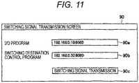
- FIG. 2 illustrates a state in which the HMI program 9 transmits a switching signal generated by the switching signal transmission screen 90 to the command switching unit 84 of the I/O program 8.
- the switching signal transmission screen 90 will be described later in detail with reference to FIG. 11 .
- the command switching unit 84 registers transmission source information of a received control command 73 in the transmission source list 87.
- the control command 73 is a message generated by the determination execution unit 70 of the control program 7, and includes an instruction on what kind of processing and operation is to be performed under a specific condition.
- the control command 73 includes contents such as "transmit a voltage value of the sensor 40 to the control program 7 every 30 milliseconds", “operate the actuator 41 for Y milliseconds at the timing of time X”, and "calculate a moving average of the voltage value of the sensor 40".
- the control command 73 transmitted from the control program 7 to the I/O program 8 is sequentially received by the reception processing unit 81 of the I/O program 8.
- the reception processing unit 81 sequentially stores the received control command 73 in a command storage area 211 of the storage device 21 (storage unit).
- Transmission data 83 is a message that is generated by the control command execution unit 80 of the I/O program 8 in accordance with the control command 73 and describes information to be transmitted to the determination execution unit 70 of the control program 7.
- the transmission data 83 includes a voltage value of the sensor 40, a value calculated by the control command execution unit 80, and the like.
- the determination execution unit 70 acquires necessary information such as the state of the device 4 by receiving the content of the transmission data 83.
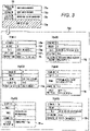
- FIG. 3 is a table illustrating an example of information included in the control command 73.
- the control command 73 includes a transmission source column 73a, a destination column 73b, a generation date and time column 73c, and a control content column 73d.
- the transmission source column 73a stores an IP address and a port number for specifying the control program 7 that has generated the control command 73.
- the destination column 73b stores an IP address and a port number specifying the I/O program 8 to execute the control program.
- the generation date and time column 73c stores the date and time when the control command 73 is generated.
- the control content column 73d stores the content of control of the control command 73.
- the control content column 73d has different contents for each control command 73, but has a command ID column 73e, a priority column 73f, a timing column 73g, and a maximum time column 73h in common.
- the command ID column 73e holds a command ID uniquely specifying the control command 73.
- the command ID is assigned by the determination execution unit 70 when the control command 73 is generated.
- the priority column 73f holds the priority of the control command 73. When the priority column 73f is blank, it indicates that the priority is the lowest.
- the timing column 73g holds the timing at which the processing described in the control content column 73d is to be executed.
- the contents of the timing can be specified in various cases such as a case where the timing is periodically executed at regular intervals, a case where conditions such as the state of the sensor are satisfied, and a case where a specified time has come.
- the maximum time column 73h holds a maximum time ( FIG. 8 to be described later) that can be allowed for processing of one control command 73. When the maximum time column 73h is blank, it indicates that the maximum time is not set.
- Control content columns 73d(1) to 73d(6) illustrate specific examples of the control content for each process to be performed.
- the control content column 73d(1) is an example of a case where input processing, that is, information acquisition from the sensor 40 is performed.
- the control content column 73d(1) includes an input processing column 73i and holds a target for acquiring information.
- the control content column 73d(2) is an example of a case where calculation processing, that is, calculation processing such as a moving average of output values of the sensor 40 is performed.
- the control content column 73d(2) includes a calculation processing column 73j and holds the content of the calculation processing.
- the control content column 73d(3) is an example of a case where the transmission processing, that is, the information is transmitted to the control program 7.
- the control content column 73d(3) includes a transmission processing column 73k and holds a transmission target.
- the control content column 73d(4) is an example of a case where output processing, that is, operation of an actuator or the like is performed.
- the control content column 73d(4) includes an output processing column 731 and holds the command ID of the operation target and the content of the operation.
- the control content column 73d(5) is an example of a case where control period setting processing, that is, a setting regarding a control period to be described later is performed.
- the control content column 73d(5) includes a control period setting column 73m and holds a control period and a start timing to be designated.
- the control content column 73d(6) is an example of a case where cancel processing, that is, the execution of the specific control command 73 is canceled.
- the control content column 73d(6) includes a cancel processing column 73n and holds a command ID of a cancel target.
- FIG. 4 is a table illustrating an example of information included in the transmission data 83.
- the transmission data 83 includes a transmission source column 83a, a transmission date and time column 83b, a command ID column 83c, and a data column 83d.
- the transmission source column 83a stores an IP address and a port number for specifying the I/O program 8 that has generated the transmission data 83.
- the transmission date and time column 83b stores the date and time when the transmission data 83 is transmitted by the I/O program 8.
- the command ID column 83c stores a command ID that specifies which control command 73 is instructed to transmit the transmission data 83.
- the data column 83d holds content (for example, target, value) of data to be transmitted.
- the determination execution unit 70 ( FIG. 2 ) of the control program 7 executed on the general-purpose OS 14 of the control node 1 generates the control command 73 based on state control set in advance for the device 4.
- the determination execution unit 70 considers what state or how to change the device 4 based on the information obtained from the sensor 40 or the like by processing involving complicated calculation or the like, and transmits the examination result to the I/O node 2 (the I/O program 8) as the control command 73. It is assumed that the control contents related to the device 4 are examined using a well-known technique, and a detailed description thereof is omitted here.
- Actual processing such as operation of the device 4 is executed on the real-time OS 24 of the I/O node 2.
- the control command execution unit 80 of the I/O program 8 executes a control command on the real-time OS 24, thereby achieving both complicated processing and processing with high punctuality.
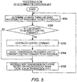
- FIG. 5 is a flowchart illustrating a procedure example of processing by the determination execution unit 70.
- the determination execution unit 70 determines at which timing and what processing the I/O program 8 is caused to execute as the control system 100 (S701). Next, the determination execution unit 70 determines whether it is necessary to generate a control command (S702), and proceeds to Step S705 when it is not necessary to generate a control command (NO in S702). Next, when generation of the control command is necessary (YES in S702), the determination execution unit 70 generates the control command 73 (S703) and causes the transmission processing unit 72 to transmit the control command to the I/O program 8 (S704).
- the determination execution unit 70 receives new transmission data 83 from the reception processing unit 71 when there is the new transmission data (S705).
- the determination execution unit 70 confirms that the transmission data 83 received by the reception processing unit 71 is transmitted from the I/O program 8 controlled by the transmission source column 83a ( FIG. 4 ), processes the transmission data 83, and uses the processed transmission data for determination in the next Step S701.
- the control program 7 constantly executes the processing of Steps S701 to S705, and transmits the control command 73 to the I/O node 2 (I/O program 8) as needed.
- the reception processing unit 81 of the I/O program 8 passes the control command 73 to the command switching unit 84.
- the command switching unit 84 selects a control command 73 to be executed by a method to be described later, and passes the corresponding control command 73 to the control command execution unit 80.
- FIG. 6 is a flowchart illustrating a procedure example of the control command reception processing of the control command execution unit 80.
- Step S801 When receiving the new control command 73 from the command switching unit 84 (S801), the control command execution unit 80 starts the control command reception flow. That is, the control command execution unit 80 sets the control command 73 to be executed along the periodic processing flow illustrated in FIG. 7 to be described later (S802). After Step S802 ends, the processing of this flowchart ends.
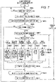
- FIG. 7 is a flowchart illustrating a procedure example of the periodic processing of the control command execution unit 80.
- the control command execution unit 80 executes a control command within a certain period of time.
- the period of this time is referred to as a "control period".
- the control period is set by the control command 73.
- the control command execution unit 80 determines whether the current time is the start time of the control period (S803), and when the current time is not the start time of the control period yet (NO in S803), monitoring of the start time of the control period is continued.
- the control command execution unit 80 starts the operation of a termination timer for the control period (S804).
- the control command execution unit 80 determines the lapse of time corresponding to the control period from a measurement time of the termination timer. In a case where the processing based on the control command 73 is not completed even after the time corresponding to the designated control period has elapsed, the control command execution unit 80 terminates the execution of the control command 73 being executed during that time (stop).
- control command execution unit 80 starts a loop of executing the control commands 73 in descending order of priority (S805).
- the control command execution unit 80 determines whether the current state satisfies the condition of the execution timing of the control command 73 (S806), and in a case where the condition of the execution timing is not satisfied (NO in S806), the process proceeds to Step S816.
- control command execution unit 80 starts the operation of the termination timer for the maximum time (S807).
- the control command execution unit 80 terminates (stops) the execution of the control command 73 being executed at that time.
- the control command execution unit 80 does not start the termination timer when the maximum time column 73h is blank.
- the control command execution unit 80 determines the processing type (control content) of the control command 73 (S808), and executes the processing of Steps S809 to S814 according to the processing type.
- Step S809 is a step for input processing.
- the control command execution unit 80 acquires information of the sensor 40 and stores the acquired information in a variable of the memory 23 so that other steps can be used.
- Step S810 is a step for calculation processing.
- the control command execution unit 80 executes the calculation processing and stores the result in a variable of the memory 23 so that other steps can be used.
- Step S811 is a step for transmission processing.
- the control command execution unit 80 generates the transmission data 83 including information to be transmitted, and causes the transmission processing unit 82 to transmit the transmission data to all the control programs 7 on the network 5.
- Step S812 is a step for output processing.
- the control command execution unit 80 operates the actuator 41 of the control target device 4 via the output processing unit 86.
- Step S813 is a step for setting processing.
- the control command execution unit 80 changes the control period.
- Step S814 is a step for cancel processing.
- the control command execution unit 80 deletes the control command 73 designated by the command ID so as not to be executed.
- control command execution unit 80 ends the termination timer for the maximum time (S815). During this time, execution of one control command 73 ends. After repeatedly executing the processing of Steps S806 to S815 for all the control commands 73, the control command execution unit 80 ends the loop of executing the control commands 73 in descending order of priority (S816).
- control command execution unit 80 ends the termination timer for the control period (S817). Then, the control command execution unit 80 returns to Step S803 and repeatedly executes the processing of Steps S803 to S817.
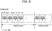
- FIG. 8 illustrates an example of an execution timing of the control command 73 in the control command execution unit 80.
- a state of execution of the control command 73 in the periodic processing flow ( FIG. 7 ) of the control command execution unit 80 is represented by a time axis.
- each control command 73 (control commands 1 ⁇ 4...) is not executed beyond the maximum time.
- each control command 73 (control command 1 ⁇ 4...) is not continuously executed beyond the control period by the termination timer for the control period. Therefore, the control command execution unit 80 can execute the control command 73 with high punctuality.
- control command execution unit 80 constantly executes the periodic processing flow and sequentially executes all the control commands 73 in order of priority for each control period, the present invention is not limited to this as long as the control command 73 can be executed with high punctuality.
- the control content of the control command 73 may be executed by interrupt processing.
- the control command 73 being executed may be interrupted by a context switch, and the control command 73 with higher priority may be executed.
- the context switch is a function of saving or restoring the state of the CPU.
- the control command processing may be executed in parallel.
- IP address and the port number are used as the information for specifying the control program 7 and the I/O program 8.
- IP address and the port number are used by the protocol on the network 5, and the information is not limited thereto as long as the information can uniquely specify the program on the network 5. The same applies to the following description.
- the administrator 36 of the control system 100 operates the control program 7A-1 after the change on the control node 1 while operating the control program 7 before the change. Then, the control command execution unit 80 of the I/O program 8 switches to process the control command 73A-1 generated by the determination execution unit 70A-1 of the control program 7A-1, and stops the control program 7 before change.
- control command execution unit 80 continues the processing of the received control command 73 stored in the storage device 21 even while switching the control program, the control program can be changed without stopping the control system 100.
- the determination execution unit 70A-1 of the control program 7A-1 after the change generates the control command 73A-1 according to the determination, and transmits the control command from the transmission processing unit 72A-1 to the I/O program 8.
- the reception processing unit 81 of the I/O program 8 receives the control command 73 and the control command 73A-1, and passes the commands to the command switching unit 84.
- FIG. 9 is a flowchart illustrating a procedure example of control command processing of the command switching unit 84.
- the command switching unit 84 When receiving the control command 73 from the reception processing unit 81 (S841), the command switching unit 84 starts the control command processing flow illustrated in FIG. 9 . First, the command switching unit 84 determines whether the control command 73 is received for the first time (S842), and if the control command 73 is not received for the first time (NO in S842), the process proceeds to Step S844.
- Step S843 the command switching unit 84 adds the IP address and the port number recorded in the transmission source column 73a of the control command 73 received at the time of the first activation of the control system 100 to the transmission source list 87 (S843).
- the command switching unit 84 determines whether the transmission source (IP address and port number) described in the transmission source column 73a of the received control command 73 is included in the transmission source list 87 (S844). Then, the command switching unit 84 proceeds to Step S846 in a case where the transmission source of the control command 73 is not included in the transmission source list 87 (NO in S844), and proceeds to Step S845 in a case where the transmission source is included in the transmission source list 87 (YES in S844).
- the command switching unit 84 checks the received control commands 73 in the command storage area 211 in order of generation date and time, and determines whether the control command 73 having the same control content has already been received (S845). When the control command 73 having the same contents has been received (YES in S845), the command switching unit 84 proceeds to Step S846. When NO in Step S844 or YES in Step S845, the command switching unit 84 discards the received control command 73 (S846).
- the command switching unit 84 passes the control command 73 to the control command execution unit 80 (S847). That is, by switching by the command switching unit 84, the control command execution unit 80 executes only the control command from the control program 7 that is the transmission source of the control command 73 received first. After the processing of Step S846 or S847, the processing of the flowchart illustrated in FIG. 9 ends.
- FIG. 10 is a flowchart illustrating a procedure example of switching signal processing of the command switching unit 84.
- the administrator 36 of the control system 100 illustrated in FIG. 2 operates the switching signal transmission screen 90 in order to process the control command 73A-1 generated by the control program 7A-1.
- the HMI program 9 transmits the switching signal to the command switching unit 84 based on the operation content on the switching signal transmission screen 90.
- the command switching unit 84 starts the switching signal processing flow illustrated in FIG. 10 . That is, the command switching unit 84 changes the transmission source information of the transmission source list 87 to the transmission source information included in the switching signal (S849).
- Step S849 the processing of the flowchart illustrated in FIG. 10 ends.
- FIG. 11 illustrates an example of a switching signal transmission screen 90 of the HMI program 9.
- the switching signal transmission screen 90 includes an area 90a for inputting the IP address and the port number of the I/O program 8, an area 90b for inputting the IP address and the port number of the control program 7A-1 of the switching destination (after the change), and a button 90c for instructing transmission of the switching signal.
- the administrator 36 of the control system 100 After connecting the changed control program 7A-1 to the network 5 and activating the program, the administrator 36 of the control system 100 transmits the switching signal using the switching signal transmission screen 90, and sets the command switching unit 84 to process the control command 73A-1.
- the transmission processing unit 82 of the I/O program 8 transmits the transmission data 83 to all the control programs on the network 5. Therefore, the control program 7 before the change and the control program 7A-1 after the change receive the same transmission data 83, and the control program 7 and the control program 7A-1 grasp the state of the device 4.
- the HMI program 9 includes the switching signal transmission screen 90, but a similar user interface may be provided in the control node 1 and the I/O node 2, and the control program 7 and the I/O program 8 may include the switching signal transmission screen 90. It is sufficient that the administrator 36 of the control system 100 can notify the command switching unit 84 of information specifying the control program 7A-1 which a switching destination, and the operation is not limited to the operation via the user interface. For example, this can also be realized by connecting a storage device storing information for specifying the switching destination to the I/O node 2 and reading this information by the command switching unit 84.
- Steps S842 and S843 the command switching unit 84 adds the transmission source information of the control command 73 at the time of initial receipt to the transmission source list 87, but the present invention is not limited to this example.
- the same step may be eliminated, and the administrator 36 of the control system 100 may designate via the HMI program 9 before the start of the control program 7.
- the changed control program 7A-1 is executed on the control node 1, but may be executed on another control node as long as the control program is connected to the network 5.
- one I/O node 2 is present in the network 5, but a plurality of I/O nodes may actually be present.
- one control program may transmit a control command to a plurality of I/O programs.
- the resource is a program or a node (computer).
- a computer used in a control system is prepared by estimating required performance from the contents of the control, but it is difficult to accurately estimate the required performance. Therefore, the performance may be insufficient after the operation of the control system. In addition, performance may be insufficient when a new function is added to the control system. According to the present embodiment configured as described above, it is possible to construct a highly scalable control system capable of adding necessary resources each time.
- control system 100 includes at least one control node (control node 1) and at least one I/O node (I/O node 2) that is connected to one or more control target devices (devices 4) and can communicate with the control node via a network.
- the control node includes a first operating system (general-purpose OS 14) and a first processor (CPU 10) that executes at least one control program (for example, control programs 7 and 7A-1) on the first operating system.
- a first operating system general-purpose OS 14
- a first processor CPU 10
- control program for example, control programs 7 and 7A-1
- the I/O node includes a second operating system (real-time OS 24) having higher punctuality than the first operating system, and a second processor (CPU 20) that executes at least one I/O program (for example, I/O program 8) on the second operating system.
- a second operating system real-time OS 24
- CPU 20 second processor
- the control program for the control node includes a determination execution unit (determination execution unit 70, 73A-1) that generates a control command (control command 73, 70A-1) based on state control set in advance for the control target device and transmits the control command to the I/O node.
- the I/O program of the I/O node includes a control command execution unit (control command execution unit 80) that stores the control command received from the control node in a storage unit (storage device 21: command storage area 211) and executes processing related to the control target device according to the control command stored in the storage unit.
- control command execution unit 80 controls the control command received from the control node in a storage unit (storage device 21: command storage area 211) and executes processing related to the control target device according to the control command stored in the storage unit.
- control command execution unit 80 when a plurality of control commands are stored in the storage unit (storage device 21), the control command execution unit (control command execution unit 80) is configured to execute processing (input processing, calculation processing, transmission processing, output processing, setting processing, cancel processing, and the like) prescribed in the control commands in descending order of priority along the control period among the plurality of control commands, and when the processing of the control command is not completed within the control period, the processing of the control command is stopped at a point in time when the control period is exceeded.
- processing input processing, calculation processing, transmission processing, output processing, setting processing, cancel processing, and the like
- the I/O program (I/O program 8) includes a command switching unit (command switching unit 84) that selects a control command to be executed from the plurality of control commands received from the plurality of control programs.
- the command switching unit is configured to select a control command generated by the control program after switching among the plurality of control programs and transmit the control command to the control command execution unit (control command execution unit 80).
- FIG. 12 is a block diagram illustrating an example of a logical configuration of a configuration management program 15 introduced into a control node 1B according to a second embodiment.
- the control node 1B has a configuration in which the configuration management program 15 is added to the control node 1 described in the first embodiment. Similarly to the control program 7, the configuration management program 15 is also executed by a CPU 10 on a general-purpose OS 14.
- the configuration management program 15 includes a master selection unit 15A, a program arrangement unit 15B, an abnormality monitoring unit 15C, a program registration unit 15D, a table synchronization unit 15E (an example of an information synchronization unit), a control program management table 15F, and a control node management table 15G.
- the configuration management program 15 takes either a master state or a slave state. Only one master-state configuration management program 15 exists on one network 5, and plays a role of distributing corresponding data to the slave-state configuration management program 15 in order to share data necessary for control. An instruction from the administrator 36 of the control system 100B is received through the HMI program 9.
- FIG. 13 is a block diagram illustrating an example of an overall configuration of a control system 100B according to the second embodiment.
- control nodes 1B are used as control nodes 1B-1 and 1B-2.
- each of the control nodes 1B-1 and 1B-2 is connected to an I/O node 2 and an HMI node 3 via the network 5.
- the control node 1B-1 includes a configuration management program 15B-1 and a control program 7B-1.
- the configuration management program 15B-1 includes a master selection unit 15B-1A, a program arrangement unit 15B-1B, an abnormality monitoring unit 15B-1C, a program registration unit 15B-1D, a table synchronization unit 15B-1E (an example of an information synchronization unit), a control program management table 15B-1F, and a control node management table 15B-1G.
- control node 1B-2 includes a configuration management program 15B-2 and a control program 7B-2.
- the configuration management program 15B-2 includes a master selection unit 15B-2A, a program arrangement unit 15B-2B, an abnormality monitoring unit 15B-2C, a program registration unit 15B-2D, a table synchronization unit 15B-2E (an example of an information synchronization unit), a control program management table 15B-2F, and a control node management table 15B-2G.
- a control node 1B-3 is an example of a control node newly connected to recover the redundant configuration of the control system 100B.
- the control node 1B-3 also has the same configuration as the control nodes 1B-1 and 1B-2. That is, the control node 1B-3 includes a configuration management program 15B-3 and a control program 7B-3.
- the configuration management program 15B-3 includes a master selection unit 15B-3A, a program arrangement unit 15B-3B, an abnormality monitoring unit 15B-3C, a program registration unit 15B-3D, a table synchronization unit 15B-3E (an example of an information synchronization unit), a control program management table 15B-3F, and a control node management table 15B-3G. The recovery of the redundant configuration using the control node 1B-3 will be described later.
- control nodes 1B-1, 1B-2, and 1B-3 are not distinguished from each other, they are referred to as "control nodes 1B " .
- the I/O node 2 executes an I/O program 8B in which the command switching unit 84 is changed to a command switching unit 84B.
- the HMI node 3 executes an HMI program 9B in which a new screen is added to the HMI program 9 and a control program 7B.
- the HMI program 9B has a control program registration screen 91 and a control node abnormality warning screen 92 which are operation screens by the GUI.
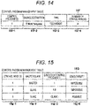
- FIGS. 14 and 15 illustrate specific examples of each table of the configuration management program 15.
- FIG. 14 illustrates an example of a structure of the control program management table 15F used by the configuration management program 15.
- FIG. 15 illustrates an example of a structure of the control node management table 15G used by the configuration management program 15.
- the control program management table 15F includes a program ID column 15f-1, a saving destination column 15f-2, a type column 15f-3, and a configuration number column 15f-4.
- the program ID column 15f-1 stores a control program ID for uniquely specifying the control program.
- the saving destination column 15f-2 stores information indicating a saving destination location of the control program.
- the type column 15f-3 stores information indicating an execution method of the control system 100B.
- the configuration number column 15f-4 stores the number of control nodes used when the control program specified by the control program ID is executed.
- the control node management table 15G includes a control node ID column 15g-1, a master/slave column 15g-2, an execution control program ID column 15g-3, and an executability column 15g-4.
- the control node ID column 15g-1 stores a control node ID for uniquely specifying a control node.
- the master/slave column 15g-2 stores information indicating whether the state of the configuration management program (control node) is master or slave. There is only one control node in the master state in one network. Note that the master/slave information may be managed by other than the control node management table 15G.
- the execution control program ID column 15g-3 stores a control program ID for uniquely specifying the control program being executed.
- the executability column 15g-4 stores information indicating whether the control program can be executed on the control node.
- control node IDs stored in the control node ID column 15g-1 are assigned to the control nodes from 1 in the order of their activation. At the time of starting the execution of the configuration management program 15, each table does not have even one record.
- FIG. 16 is a flowchart illustrating a procedure example of start processing of the master selection unit 15A.
- the administrator 36 of the control system 100B starts operation of the control nodes 1B-1 and 1B-2 through a user interface 35. Accordingly, the configuration management program 15B-1 starts the start flow of the master selection unit 15B-1A illustrated in FIG. 16 .
- the master selection unit 15B-1A of the control node 1B-1 determines whether there is a configuration management program (control node) in the master state on the network 5 (S1501).
- the master selection unit 15B-1A proceeds to Step S1502 when the configuration management program 15 in the master state does not exist (NO in S1501), and proceeds to Step S1504 when the configuration management program 15 in the master state exists (YES in S1501).
- Step S1501 the master selection unit 15B-1A determines in Step S1501 that the configuration management program 15 in the master state does not exist on the network 5 (NO in S1501), and sets the configuration management program 15B-1 as the master (S1502). Then, the master selection unit 15B-1A adds information on its own control node 1B-1 to the control node management table 15B-1G by the table synchronization unit 15B-1E (S1503). After the processing of Step S1503, the process proceeds to Step S1506.
- the master selection unit 15B-2A of the control node 1B-2 sets its own configuration management program 15B-2 as a slave (S1504). Then, the master selection unit 15B-2A notifies the master selection unit 15B-1A of the control node 1B-1 of the information on the control node 1B-2 (S1505).
- Step S1503 or S1505 the master selection unit 15A of each of the configuration management programs 15B-1 and 15B-2 causes the abnormality monitoring unit 15C to start processing (S1506).
- the processing of the abnormality monitoring unit 15C in Step S1506 will be described later with reference to FIG. 25 .
- Step S1506 the processing of this flowchart ends.
- FIG. 17 is a flowchart illustrating a procedure example of control node management processing of the master selection unit 15A.
- the master selection unit 15B-1A of the control node 1B-1 in the master state starts the control node management flow.
- the master selection unit 15B-1A additionally registers the received information on the control node 1B-2 in the control node management table 15B-1G by the table synchronization unit 15B-1E (S1508).
- the master selection unit 15B-1A causes the program arrangement unit 15B-1B to start the program arrangement flow illustrated in FIG. 21 (S1509). At this time, since the control program is not registered in a control program management table 15B-1F, the control program is not arranged. After the processing of Step S1509, the processing of this flowchart ends.
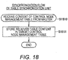
- FIG. 18 is a flowchart illustrating a procedure example of synchronization processing of the table synchronization unit 15E.
- Step S1523 of FIG. 21 described later the contents of the control node management table 15B-1G are notified from the configuration management program 15B-1 in the master state to the table synchronization unit 15B-2E of the configuration management program 15B-2 in the slave state.
- the table synchronization unit 15B-2E Upon receiving the contents of the control node management table 15B-1G (S1510), the table synchronization unit 15B-2E starts the synchronization flow illustrated in FIG. 18 . That is, the table synchronization unit 15B-2E stores the content of the received control node management table 15B-1G in the control node management table 15B-2G (S1511). After the processing of Step S1511, the processing of this flowchart ends.
- the table synchronization unit 15B-2E registers all the received information in the control node management table 15B-2G.
- the contents of the control node management tables 15B-1G on the configuration management program 15B-1 in the master state are the same as the contents of all the control node management tables 15G in the slave state.
- the configuration management program 15 starts execution of an abnormality monitoring unit 15C described later in Step S1504.
- FIG. 19 illustrates an example of the control program registration screen 91.
- the administrator 36 of the control system 100B performs an operation to arrange the execution file of the control program 7B in the storage device 31 of the HMI node 3 so as to start the execution of the control program 7B in the redundant configuration.
- the administrator 36 inputs the saving location of the execution file of the control program 7B to the control program saving destination column 91a. Further, the administrator 36 inputs necessity of implementation of redundancy and the number of control nodes in a case of redundancy to a redundancy configuration setting column 91b, and presses a control program registration button 91c.
- FIG. 20 is a flowchart illustrating a procedure example of program registration processing of the program registration unit 15D. This processing is processing for starting the control program.
- the control program registration screen 91 notifies the program registration unit 15B-1D in the configuration management program 15B-1 in the master state of the input information.
- the program registration unit 15B-1D adds the input information to the control program management table 15B-1F (S1513), and causes the program arrangement unit 15B-1B to start the program arrangement flow (S1514).
- the program registration unit 15B-1D transmits the content of the control program management table 15B-1F to the table synchronization unit 15B-2E of the configuration management program 15B-2 for synchronization (S1515).
- the content of the control program management table 15B-1F in the master state matches the content of the control program management table 15F of all the configuration management programs 15 in the slave state.
- FIG. 21 is a flowchart illustrating a procedure example of the program arrangement processing of the program arrangement unit 15B.
- the program arrangement unit 15B-1B in the configuration management program 15B-1 in the master state starts the program arrangement flow illustrated in FIG. 21 in response to an instruction from the program registration unit 15B-1D or the like (S1517).
- the program arrangement flow is looped for each control program registered in the control program management table 15B-1F.
- the program arrangement unit 15B-1B compares the number of configurations described in the control program management table 15B-1F with the content of the control node management table 15B-1G (S1518). In a case where the number of control nodes executing each control program and the above-described number of components match (YES in S1518), the program arrangement unit 15B-1B proceeds to Step S1522 and ends the loop.
- the program arrangement unit 15B-1B refers to the control node management table 15B-1G and determines whether there is a control node capable of executing the control program (S1519). When there is no control node capable of executing the control program (NO in S1519), the program arrangement unit 15B-1B proceeds to Step S1522.
- the program arrangement unit 15B-1B notifies the program arrangement unit 15B of the corresponding control node to start the program execution flow (S1520). For example, in a case where the control node 1B-1 and the control node 1B-2 can execute the control program, the program arrangement unit 15B-1B starts the program execution flow by the program arrangement unit 15B-1B itself and causes the program arrangement unit 15B-2B to start the program execution flow.
- the program arrangement unit 15B-1B updates the execution control program ID column 15g-3 of the control node management table 15B-1G (S1521).
- the loop processing ends (S1522) .
- the program arrangement unit 15B-1B notifies the table synchronization unit 15E of another configuration management program 15 of the information of the control node management table 15B-1G.
- the information on the control node management table 15B-1G is synchronized with the information of all the other control node management tables 15G (S1523).
- FIG. 22 is a flowchart illustrating a procedure example of program execution processing of the program arrangement unit 15B.
- the program arrangement unit 15B-1B acquires the execution file of the target control program 7B-1 from the HMI node 3, and enters a state where the execution file can be executed as the control program 7B-1 (S1525).
- the program arrangement unit 15B-1B notifies the command switching unit 84B in the I/O program 8B of the I/O node 2 of the IP address and the port number of the control program 7B-1 (S1526), and starts execution of the control program 7B-1 (S1527).
- the program arrangement unit 15B-2B operates in the same manner. After Step S1527 ends, the processing of this flowchart ends.
- FIG. 23 is a flowchart illustrating a procedure example of the configuration notification processing of the command switching unit 84.
- the command switching unit 84B of the I/O program 8B When receiving the transmission source information of the control program 7B-1 from the configuration management program 15B-1 (S1528), the command switching unit 84B of the I/O program 8B starts the configuration notification flow. That is, the command switching unit 84B adds the received transmission source information to the transmission source list 87 (S1529). As a result, the control command 73 output from both the control programs 7B-1 and 7B-2 can be processed. After the processing of Step S1529, the processing of this flowchart ends.
- FIG. 24 is a block diagram illustrating an example of a control command switching operation according to the second embodiment.
- the control programs 7B-1 and 7B-2 both transmit the control commands 73B-1 and 73B-2 according to the processing flow of the determination execution unit 70 illustrated in FIG. 5 . Since the contents of the control programs 7B-1 and 7B-2 are the same, exactly the same contents are written in the control content columns 73d of the control commands 73B-1 and 73B-2.
- the transmitted control commands 73B-1 and 73B-2 are received by the reception processing unit 81 of the I/O program 8B and processed by the command switching unit 84B according to the control command processing flow in FIG. 9 .
- the program arrangement units 15B-1B and 15B-2B of the configuration management programs 15B-1 and 15B-2 notify the command switching unit 84 of the I/O program 8B, and add the IP addresses and the port numbers of the control programs 7B-1 and 7B-2 to the transmission source list 87. Accordingly, YES is determined in Step S844 in FIG. 9 , and both the control commands 73B-1 and 73B-2 are not discarded in Step S846.
- Step S845 it is checked whether the same control command has already been registered. For example, when the control command 73B-1 arrives at the command switching unit 84, the control command 73B-2 is determined as YES in Step S845 and is discarded in Step S846. Through this process, the control command that always arrives is passed to the control command execution unit 80. In a case where the control node 1B-1 or 1B-2 fails, the control command 73B-1 or 73B-2 transmitted by the remaining one control node is passed to the control command execution unit 80 by the command switching unit 84B, whereby the control of the control system 100B is continued.
- FIG. 25 illustrates a flowchart of monitoring processing of the abnormality monitoring unit 15C.
- FIG. 25 is a flowchart illustrating a procedure example of the monitoring processing of the abnormality monitoring unit 15C.
- the abnormality monitoring unit 15C checks the state of the control node to be monitored (S1530). For example, the abnormality monitoring unit 15C monitors whether or not there is an abnormality for a control node having a control node ID (for example, a number) smaller by one than that of the abnormality monitoring unit itself.
- the abnormality monitoring unit 15C of the control node having the control node ID "1" (minimum) monitors the control node having the maximum control node ID. That is, the control nodes 1B on the network 5 monitor each other in a row.
- the configuration management programs 15B-1 and 15B-2 monitor each other. Specific examples of the monitoring method include, but are not limited to, a method of checking whether there is a response by a ping response, and a method of checking whether the control node 1B to be monitored periodically transmits a control command.
- the abnormality monitoring unit 15C determines whether there is an abnormality in the control node to be monitored (S1531), and continues the process of determining the presence or absence of an abnormality when there is no abnormality in the control node (NO in S1531).
- the abnormality monitoring unit 15C first determines whether the configuration management program 15 of the control node in which the abnormality occurs is in the master state (S1532). When the corresponding configuration management program 15 is not in the master state (NO in S1532), the process proceeds to Step S1534.
- the abnormality monitoring unit 15C determines that the control node to be monitored is in the master state (YES in S1532), the configuration management program 15 of the control node in which the abnormality has occurred is in the master state, and thus, the abnormality monitoring unit 15C sets its own configuration management program 15B-2 as the master (S1533).
- the abnormality monitoring unit 15C notifies the abnormality monitoring unit 15C of the configuration management program 15 in the master state and the HMI program 9B of occurrence of the abnormality, that is, information on the control node in which the abnormality occurs (S1534).
- the abnormality monitoring unit 15B-2C in the slave state detects the abnormality of the control node 1B-1 in the master state, sets the configuration management program 15B-2 to the master state, and notifies itself of the occurrence of the abnormality.
- Step S1534 the abnormality monitoring unit 15C proceeds to Step S1530.
- FIG. 26 illustrates an example of a control node abnormality warning screen.
- the HMI program 9B receives the notification of the occurrence of the abnormality of the control node, and displays a control node abnormality warning screen 92 illustrated in FIG. 26 to notify the administrator 36 of the control system 100B of the abnormality of the control node.
- a control node abnormality warning screen 92 illustrated in FIG. 26 to notify the administrator 36 of the control system 100B of the abnormality of the control node.
- FIG. 26 "stop control node [1]! is displayed.
- FIG. 27 is a flowchart illustrating a procedure example of the recovery processing of the abnormality monitoring unit 15C.
- the abnormality monitoring unit 15C of the configuration management program 15 in the master state Upon receiving the notification of the occurrence of the abnormality in the control node 1B (S1535), the abnormality monitoring unit 15C of the configuration management program 15 in the master state starts the recovery flow illustrated in FIG. 27 .
- a case where an abnormality occurs in the control node 1B-1 will be described as an example.
- the abnormality monitoring unit 15C excludes information on the control node 1B-1 in which an abnormality has occurred from the control node management table 15G (S1536). Then, the abnormality monitoring unit 15C causes the program arrangement unit 15B to start the program arrangement flow illustrated in FIG. 21 (S1537). When there is a control node capable of executing the control program at this time on the network 5, the execution of the control program 7B is started by the program arrangement flow, and the redundant state is recovered.
- the configuration management program 15B-3 starts to be executed on the control node 1B-3, and the configuration management program 15B-3 becomes a slave state along the start flow ( FIG. 16 ) of the master selection unit 15B-3A. Then, in Step S1505 in FIG. 16 , the master selection unit 15B-3A notifies the master selection unit 15B-2A that the control node 1B-3 is available in the slave state.
- control node management flow illustrated in FIG. 17 is started in the master selection unit 15B-2A of the control node 1B-2 (S1507). Then, the master selection unit 15B-2A adds the information on the control node 1B-3 to the control node management table 15B-2G (S1508), and the program arrangement flow is started (S1509). The newly connected control node 1B-3 is added as a slave. Then, in the program arrangement flow, the control program 7B starts to be executed on the control node 1B-3, and the control program 7B recovers to a redundant state again.
- control programs 7B-1, 7B-2, and 7B-3 in the present embodiment do not need to manage the states of other control programs. As in the case of executing the control program without redundancy, it is sufficient to create a program for generating the control command 73, and thus, the development of the control program is relatively easy.
- FIG. 28 is a block diagram illustrating an example in which the normal monitoring program is introduced into the control node according to the first modification of the second embodiment
- control command to be executed is selected by the command switching unit 84B, but the present invention is not limited to this example.
- the normal monitoring programs 16B-4 and 16B-5 may be provided in the control nodes 1B-4 and 1B-5, respectively.
- the normal monitoring programs 16B-4 and 16B-5 become standby systems when the control nodes executing the same control program 7B exist on the network 5. Then, the normal monitoring program 16B-5 receives the control command 73B-4 transmitted by the control program 7B-4 of the control node 1B-4, and monitors whether the control node 1B-4 is transmitting the control command 73B-4. Since the normal monitoring program 16B-5 receives the control command 73B-4 for the purpose of confirming whether the control node 1B-4 is normally transmitting the control command, the received control command 73B-4 is not transmitted to the I/O node 2.
- the normal monitoring program 16B-5 discards the control command 73B-5 generated by the control program 7B-5 of the control node 1B-5.
- the normal monitoring program 16B-5 may determine that the control node 1B-4 has failed when the control command 73B-4 is not transmitted even after a certain period of time, and thereafter transmit the control command 73B-5 from the normal monitoring program 16B-5 to the I/O node 2.
- the normal monitoring program does nothing.
- FIG. 29 is a block diagram illustrating an example in which a plurality of control programs is operated on one control node according to a second modification of the second embodiment.
- one type of control program is executed on one control node, but a plurality of control programs may be operated on one control node.
- an I/O program (X) is stored as an I/O program 8B in an I/O node 2 (I/O node (1)) that controls the device (1)
- an I/O program (Y) is stored as an I/O program 8B in an I/O node 2B-1 (I/O node (2)) that controls the device (2).
- control programs (X) 7B-6 and 7B-9 that control the two I/O nodes 2 and 2B-1 and the control programs (Y) 7B-7 and 7B-8 are appropriately arranged on the two control nodes 1B-6 and 1B-7. Note that each of the I/O nodes 2 and 2B-1 may be able to control the devices (1) and (2).
- a control program (X) 7B-6, a control program (Y) 7B-8, and a configuration management program 15B-6 are arranged in the control node 1B-6.
- a control program (Y) 7B-7, a control program (X) 7B-9, and a configuration management program 15B-7 are arranged in the control node 1B-7.
- the command switching unit 84B selects a first-come, first-served control command of the control commands 73B-1 and 73B-2, and executes the corresponding control command, thereby performing only redundancy.
- a configuration in which a plurality of control programs are operated on one control node can be used for improving reliability.
- control system is configured to execute three or more same control programs on the same network 5. Then, in this control system, when the contents of the control commands transmitted by the control programs received at the same timing do not all match, the command switching unit 84B passes, to the control command execution unit 80, a control command that comes first in a large number of control commands with the same control contents.
- the I/O program (I/O program 8B) includes the command switching unit (command switching unit 84B) that selects a control command to be executed from the plurality of control commands received from the plurality of control programs, and the control program is executed on at least two control nodes (control nodes 1B-1 to 1B-3).
- the command switching unit is configured to send only the control command received from the control node to the control command execution unit (control command execution unit 80).
- the I/O program (I/O program 8B) includes the command switching unit (command switching unit 84B) that selects the control command to be executed from the plurality of control commands received from the plurality of control programs, and the control program is executed on at least three control nodes (control nodes 1B-1 to 1B-3).
- the command switching unit is configured to compare control contents of control commands received at the same timing, and when control commands having different control contents are included, select a large number of control commands having the same control contents and transmit the selected control commands to the control command execution unit (control command execution unit 80).
- each control node includes the configuration management program (configuration management program 15).
- the configuration management program includes the master selection unit (master selection unit 15A) that selects the control node operating in the master state from among the plurality of control nodes, sets its own control node to the slave state, sets its own control node to the master state when there is no control node in the master state, and transmits information on its own control node to other control nodes; the information synchronization unit (table synchronization unit 15E) that synchronizes information on each control node in the control node in the master state and the control node in the slave state with the control node management table (control node management table 15G) included in each control node, the program registration unit (program registration unit 15D) that receives information on the control program and information on a redundant configuration setting designated by a user interface, the program arrangement unit (program arrangement unit 15B) that, when the redundant configuration is requested, refers to the control node management table to determine two or more control nodes that execute the control program in the redundant configuration and cause the determined control nodes to execute the control program, and the abnormality monitoring
- the information synchronization unit excludes the control node having an abnormality from the control node management table, and the program arrangement unit selects another control node capable of executing the control program from the control node management table and causes the selected control node to execute the control program.
- control system 100B in a case where there is' no other control node capable of executing the control program in the control node management table (control node management table 15G), when a new control node (control node 1B-3) is connected to the network, the master selection unit (master selection unit 15A) detects the connection and adds information on the new control node to the control node management table, and the program arrangement unit (program arrangement unit 15B) determines the control node added to the control node management table as the control node that executes the control program in the redundant configuration.
- master selection unit master selection unit
- program arrangement unit program arrangement unit 15B
- control system control system 100B
- configuration management program configuration management program 15
- abnormality monitoring unit abnormality monitoring unit 15C
- master selection unit master selection unit 15A
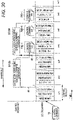
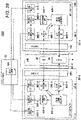
- FIG. 30 illustrates an example of execution timings of the control program and the I/O program of the control system according to the first embodiment.
- the example illustrated in FIG. 30 illustrates execution timings of the control program 7 and the I/O program 8 in time series in the configuration of the control system 100 illustrated in FIG. 2 .
- the I/O program 8 that has received the control command 73 transmits the transmission data 83.
- the transmission data 83 is received by the control program 7, and the control program 7 generates the control command 73 (S7101).
- the maximum processing time of the control program 7 is longer than 2T, the interval at which the control command 73 is transmitted also becomes long.
- FIG. 31 is a block diagram illustrating an example of an overall configuration of a control system according to a third embodiment.
- a control system 100C is configured as illustrated in FIG. 31 .
- the two control nodes 1B used in the second embodiment are set as control nodes 1C-1 and 1C-2, respectively, and the same control program 7 is executed.
- the control programs 7 are referred to as control programs 7C-1 and 7C-2, respectively.
- a control program 7C-1 and a configuration management program 15C-1 are arranged in the control node 1C-1
- a control program 7C-2 and a configuration management program 15C-2 are arranged in the control node 1C-2.
- the I/O node 2 executes an I/O program 8C.
- FIG. 32 illustrates an example of execution timings of the control program and the I/O program of the control system according to the third embodiment.
- control programs 7C-1 and 7C-2 sequentially process the transmission data 83C (S7101 to S7104), and thus, the control command execution unit 80 always executes the latest control commands 73C-1 and 73C-2. As a result, the control of the device 4 can be executed with a small delay time.
- the delay time can be shortened by adding three or four control nodes 1B in accordance with the required delay time. Therefore, for example, even in a case where the performance of the entire control system 100C is insufficient later, it is possible to measure the performance improvement by adding the control node 1B each time.
- the present embodiment requires less cost than replacement with a high-performance computer and enables efficient investment.
- the I/O program 8C is obtained by additionally modifying some functions of the I/O program 8, and includes a transmission processing unit 82C, a command switching unit 84 (not illustrated), a transmission source list 87C (refer to FIG. 35 ), and a scale-out configuration table 89 (refer to FIG. 36 ) as illustrated in FIG. 31 .
- the HMI program 9C used in this configuration has a scale-out configuration setting screen 93.
- the administrator 36 of the control system 100C first operates the control program 7C in the redundant configuration by the method described in the second embodiment. Next, the administrator 36 uses the scale-out configuration setting screen 93 to send a signal to the transmission processing unit 82C of the I/O program 8C to take the scale-out configuration.
- a specific example of the scale-out configuration setting screen 93 is illustrated in FIG. 33 .
- FIG. 33 illustrates an example of the scale-out configuration setting screen 93.
- the scale-out configuration setting screen 93 includes an I/O program setting column 93a and a scale-out start button 93b.
- a scale-out start signal is transmitted to the transmission processing unit 82C of the I/O program 8.
- the transmission processing unit 82C that has received the scale-out start signal transmits (distributes) the transmission data 83C in the order set for the target control node.
- FIG. 34 is a flowchart illustrating a procedure example of scale-out configuration start processing of the transmission processing unit 82C.
- the transmission processing unit 82C Upon receiving the scale-out start signal from the HMI program 9C (S8201), the transmission processing unit 82C starts the scale-out configuration start flow illustrated in FIG. 34 . First, the transmission processing unit 82C refers to the transmission source list 87C illustrated in FIG. 35 (S8202).
- FIG. 35 illustrates an example of a structure of the transmission source list 87C.
- the transmission source list 87C includes at least a transmission source column 87a and an order column 87b.
- the transmission source column 87a stores an IP address and a port number for specifying a control program (for example, control commands 73C1 and 73C2) for generating control commands (for example, control commands 73C1 and 73C2) .
- the order column 87b stores the execution order of a plurality of control programs designated from the control programs.
- control command 73 includes information on a transmission source and an order for specifying the control program
- command switching unit 84 can create the transmission source list 87C using the information.
- the transmission processing unit 82C determines the order of transmitting the transmission data 83C to the control program based on the content of the transmission source list 87C (S8203), and sets the scale-out configuration table 89 (S8204). After Step S8204 ends, the processing of this flowchart ends.
- FIG. 36 illustrates an example structure of the scale-out configuration table 89.
- the scale-out configuration table 89 includes at least a transmission source column 89a and an order column 89b. The information in each column of the scale-out configuration table 89 is obtained from the transmission source list 87C.
- the transmission source column 89a stores an IP address and a port number for specifying a control program (for example, control commands 73C1 and 73C2) for generating control commands (for example, control commands 73C1 and 73C2).
- a control program for example, control commands 73C1 and 73C2
- control commands 73C1 and 73C2 for example, control commands 73C1 and 73C2
- the order column 89b stores the execution order of the plurality of control programs.
- numerical values are set in order from 1, whereby the order of transmitting the transmission data 83C is defined.
- FIG. 37 is a flowchart illustrating a procedure example of transmission processing of the transmission processing unit 82C.
- the transmission processing unit 82C receives the transmission data 83C from the control command execution unit 80 (S8205), and starts the transmission processing flow illustrated in FIG. 37 .
- the transmission processing unit 82C checks whether the scale-out configuration table 89 exists (S8206). When the scale-out configuration table 89 is set (YES in S8206), the transmission processing unit 82C determines a transmission destination (destination control program) according to the order of the order column 89b, and transmits transmission data (S8207). That is, the transmission processing unit 82C transmits the transmission data 83C to the control program 7C-1 in the order "1" in the scale-out configuration table 89, for example. Then, when the next transmission processing flow is executed, the transmission data 83C is transmitted to the control program 7C-2 in the order "2 ". When the transmission data is transmitted to all the control programs listed in the scale-out configuration table 89, the transmission data is transmitted again from the order "1".
- the transmission processing unit 82C transmits the transmission data to all the control programs on the network 5 as in the first embodiment or the second embodiment (S8208). After the processing of Step S8207 or S8208, the processing of this flowchart ends.
- control node 1 Since the control node 1 executes the control program 7 on the general-purpose OS 14, the maximum time required for processing cannot be guaranteed. Therefore, in practice, it is necessary to configure the control system using the number of control nodes 1 having a margin larger than the minimum required number.
- control system 100C is configured such that at least two control nodes (control nodes 1C-1 and 1C-2) sequentially receive the result of processing by the I/O program (I/O program 8C) of the I/O node (I/O node 2), and in each control node, the determination execution unit (for example, determination execution unit 70) of the control program (control programs 7C-1 and 7C-2) generates the control command based on the received result of the processing, and sequentially transmits the control command to the I/O node.
- the determination execution unit for example, determination execution unit 70
- FIG. 38 is a block diagram illustrating an example of an overall configuration of a control system according to a fourth embodiment.
- a control system 100D of the present embodiment uses two I/O nodes 2 as I/O nodes 2D-1 and 2D-2.
- the control system 100D has a configuration in which the I/O node 2D-1 is a normal system and the I/O node 2D-2 is added as a standby system. Normally, the I/O node 2D-1 controls the device 4, and when the I/O node 2D-1 fails, the I/O node 2D-2 controls the device 4 instead.
- the I/O node 2D-1 is connected to the device 4 by the cable 6 as in the first embodiment.
- the I/O node 2D-2 is also connected to the device 4 using the cable 6D-2.
- the cable 6 and the cable 6D-2 are connected in parallel to a terminal so that the I/O node 2D-1 and the I/O node 2D-2 can simultaneously acquire information from the sensor 40 of the device 4 and operate the actuator 41.
- I/O programs 8D-1 and 8D-2 operating on the I/O nodes 2D-1 and 2D-2 respectively include period synchronization units 88D-1 and 88D-2.
- the period synchronization unit 88D-1 operates as a server, and distributes time information of a clock used as a reference of a control period by a control command execution unit 80D-1 via a network 5.
- the period synchronization unit 88D-2 operates as a client, and adjusts a clock of a control command execution unit 80D-2 based on the time received from the period synchronization unit 88D-1 to match the timing of the control period.
- a protocol defined in IEEE1588 or IEEE802.1 AS can be used to implement the period synchronization units 88D-1 and 88D-2, but the present invention is not limited thereto as long as the timing can be matched with accuracy required for controlling the device 4.
- the period synchronization unit 88D-2 may determine that the I/O node 2D-1 is abnormal when the time cannot be received from the period synchronization unit 88D-1.
- a control program 7D generates a control command 73D and transmits the control command 73D to the I/O programs 8D-1 and 8D-2. Both of the I/O programs 8D-1 and 8D-2 similarly process the control command 73D. Since the I/O programs 8D-1 and 8D-2 have the same control period and process the same control command 73D, the same input processing and output processing are performed on the device 4 at the same timing. When an abnormality occurs in the I/O node 2D-1, the control of the device 4 is continued by the I/O program 8D-2.
- the transmission processing unit 82D-2 of the I/O program 8D-2 checks with the period synchronization unit 88D-2 to determine the presence or absence of abnormality of the I/O node 2D-1.
- the transmission processing unit 82D-2 does not transmit and discards the transmission data 83D-2 when the I/O node 2D-1 is normal, and transmits the transmission data 83D-2 to the control program 7D when the I/O node 2D-1 is abnormal. Accordingly, data is transmitted from only one of the I/O programs 8D-1 and 8D-2 to the control program 7D.
- the I/O program 8D-1 is provided with a reception processing unit 81D-1, a transmission processing unit 82D-1, an input processing unit 85D-1, and an output processing unit 86D-1, but these processing units are similar to the corresponding processing units of the first embodiment, and thus detailed descriptions thereof will be omitted.
- the I/O program 8D-2 is provided with a reception processing unit 81D-2, an input processing unit 85D-2, and an output processing unit 86D-2, but detailed descriptions thereof will be similarly omitted.
- control periods are synchronized in a row in order to detect a failure of the I/O node by the period synchronization unit. That is, one standby system I/O node that performs control period synchronization from the period synchronization unit of one I/O node of the normal system and another standby system I/O node that performs control period synchronization from the period synchronization unit of the standby system I/O node are sequentially connected.
- the I/O program 8D-2 controls the device 4 in parallel even while the I/O program 8D-1 normally executes the control of the device 4, but the present invention is not limited to this example.
- the output processing unit 86D-2 in the I/O program 8D-2 may be invalidated to ignore all instructions from the control command execution unit 80D-2, and the output processing unit 86D-2 may be validated to perform the output processing to the device 4 at the time point the period synchronization unit 88D-2 detects the abnormality of the I/O node 2D-1. In this case, it is also possible to cope with a case where the actuator 41 of the device 4 cannot receive a plurality of signals for control.
- the configuration of the present embodiment is used for redundancy of the I/O node, it can also be used as a scale-out configuration that distributes control processing.
- a scale-out configuration that distributes control processing.
- FIG. 39 illustrates an example of the execution timing of each of the I/O programs in a case where one I/O node is used and in a case where two I/O nodes (normal operation, standby) according to the fourth embodiment are used.
- FIG. 39 illustrates an example in which a configuration using one I/O node (one I/O program 8) and a state of processing in two I/O programs in a case where scale-out is performed using this configuration are illustrated in time series.
- a configuration using one I/O node one I/O program 8
- a state of processing in two I/O programs in a case where scale-out is performed using this configuration are illustrated in time series.
- three types of processing can be performed using two I/O programs 8D-1 and 8D-2. This makes it possible to shorten the control period.
- an I/O node with lower performance can perform control in an equivalent control period.
- the present embodiment can also be used to shorten a substantial control period as viewed from the device by executing the same processing at different control period timings.
- FIG. 40 illustrates an example of the execution timing of each I/O program in a case where one I/O node is used and in a case where the control period is shifted using two I/O nodes (normal operation, standby) according to the fourth embodiment.
- FIG. 40 is an example in which a configuration using one I/O node (one I/O program 8) and a state of processing in two I/O programs when scale-out with a shifted control period is performed using this configuration are illustrated in time series. As illustrated, a case where the start timing of the control period of the I/O program 8D-4 is delayed by 1/2T with respect to the I/O program 8D-3, and the I/O programs 8D-3 and 8D-4 are both operated by the control command T will be considered. Although both the I/O programs have the control period T, when viewed from the control target device 4, the same processing is performed every 1/2T, and thus, it is possible to realize control equivalent to that in a case where the control is executed in the control period 1/2T.
- a control command having a setting process for shifting the start timing is transmitted to the I/O program 8D-4 by the control period setting column 73m ( FIG. 3 ). Further, a control program 7D for transmitting the same control command to the I/O programs 8D-3 and 8D-4 is created.
- control program 7D exists on the network 5, but a plurality of control programs 7D may actually exist.
- configurations described in the first to third embodiments and the present embodiment can be used in combination.
- control system 100D connects at least two I/O nodes (I/O nodes 2D-1 and 2D-2) to the control target device so that information can be simultaneously acquired and operated, and causes one of the plurality of I/O nodes to operate as a normal system and another I/O node to operate as a standby system.
- control system 100D control system 100D
- at least two I/O nodes I/O nodes 2D-1 and 2D-2 are connected to the same control target device in a state where control periods thereof are synchronized.
- the control system is configured such that a determination execution unit (for example, determination execution unit 70) of a control program divides a control content to be executed into at least two control commands and describes the control content, and transmits the control commands in which the control content is divided to each I/O node connected to the control target device.
- control system 100D at least two I/O nodes (I/O nodes 2D-1 and 2D-2) are connected to the same control target device in a state where control periods thereof are synchronized.
- This control system is configured such that the determination execution unit (for example, the determination execution unit 70) of the control program (control program 7D) generates a control command having the same control content in which start timings in control command execution units (control command execution units 80D-1 and 80D-2) of I/O programs (I/O programs 8D-1 and 8D-2) in each I/O node are set to be shifted for each I/O program within a range of a control period, and transmits the control command to each of two or more I/O nodes connected to a control target device, and the control command execution unit of the I/O program in each I/O node executes the control command at the set start timing.
- the above-described embodiments describe the configurations of the control system in detail and specifically in order to describe the present invention in an easy-to-understand manner, and are not necessarily limited to those having all the described components. Further, some of the configurations of an embodiment can be replaced with the components of another embodiment. In addition, the component of another embodiment can be added to the configuration of an embodiment. Further, it is possible to perform addition/replacement/deletion on other components with respect to some of the configurations of each embodiment.
- a plurality of processes may be executed in parallel or the processing order may be changed within a range not affecting the processing result.
- control lines or information lines are illustrated as necessary for explanation, and all the control lines or information lines are not necessarily illustrated on products. In practice, it may be considered that almost all the components are connected to each other.
Landscapes
- Engineering & Computer Science (AREA)
- Physics & Mathematics (AREA)
- General Physics & Mathematics (AREA)
- Theoretical Computer Science (AREA)
- Automation & Control Theory (AREA)
- General Engineering & Computer Science (AREA)
- Programmable Controllers (AREA)
Abstract
Description
- The present invention relates to a control system that performs control using a computer, for example, in the fields of factory automation (FA) and process automation (PA).
- In general, in the fields of factory automation (FA) and process automation (PA), a control system using a computer is introduced in a manufacturing process in a factory or the like, a production process of a chemical product or the like, or the like. The control system performs control by a computer such as a programmable logic controller (PLC) executing a computer program.
- An outline of processing of such a control system will be described. The computer acquires information necessary for control, such as temperature, pressure, and rotational speed, from a sensor. The computer operates an actuator, a motor, and the like based on the information. A content to be controlled is defined in a program, and the computer performs control by executing the program. The control needs to be performed at an appropriate timing, and the performance or degree that can be controlled at the appropriate timing is referred to as "punctuality".
- For example,
PTL 1 discloses a plant control system in which sequential control logic (various determinations and the like) is executed by a PLC, complex arithmetic processing (numerical operation such as convergence operation) is executed on a general-purpose OS, and functions to be processed are allocated. - PTL 1:
JP 2009-093375 A - In recent years, there is development of artificial intelligence technology represented by automatic driving of automobiles. In the field of artificial intelligence technology, it is required to introduce advanced determination processing by complex calculation processing such as deep learning inference processing into a control system. The implementation of this determination processing has the following problems.
- The control system needs to perform control with high punctuality. PLC and the like ensure punctuality by executing programs on a real-time operating system (OS) with high punctuality. The real-time OS has functions and characteristics for executing processing with time constraints. Meanwhile, a program that performs complicated processing such as inference processing may be developed on the premise of execution on a general-purpose OS, and it is difficult to execute the program on a real-time OS.
- In a manufacturing process of a factory or the like, equipment may continue to operate for several months to several years, and it is assumed that the control system is not stopped. Meanwhile, in order to add a new function to the control system, it is necessary to temporarily stop the control system. In addition, even in a case where software or hardware constituting the control system needs to be replaced due to aging, the control system cannot be frequently stopped, and the replacement may be delayed.
- As described above, the control system is required to continue to operate. Therefore, the control system is configured to be redundant by using two or more computers, and the operation of the control system is continued even when one computer fails. At this time, the program executed by each computer needs to be synchronized in timing and information with the programs of another computer, and have performance that does not impair punctuality even at the time of failure, and thus has a high degree of difficulty.
-
Patent Literature 1 does not disclose a technique for changing a program, a computer, or the like of a control system while the control system requiring such high punctuality is operated. - The present invention has been made in view of the above circumstances, and an object of the present invention is to enable change of resources used in a control system without stopping the control system while maintaining punctuality.
- In order to solve the above problem, a control system according to one aspect of the present invention includes at least one control node and at least one I/O node that is connected to one or more control target devices and is communicable with the control node via a network.
- The control node includes a first operating system and a first processor that executes at least one control program on the first operating system.
- The I/O node includes a second operating system having higher punctuality than the first operating system, and a second processor that executes at least one I/O program on the second operating system.
- The control program for the control node includes a determination execution unit that generates a control command based on state control set in advance for the control target device and transmits the control command to the I/O node.
- The I/O program of the I/O node includes a control command execution unit that stores a control command received from the control node in a storage unit and executes processing related to the control target device according to the control command stored in the storage unit.
- According to at least one aspect of the present invention, it is possible to change a resource used in a control system without stopping the control system while maintaining punctuality.
- Objects, configurations, and effects other than those described above will be clarified by the following description of an embodiment.
-
- [
FIG. 1] FIG. 1 is a block diagram illustrating an example of an overall configuration of a control system according to a first embodiment of the present invention. - [
FIG. 2] FIG. 2 is a block diagram illustrating an example of a logical configuration of a control program and an I/O program of the control system according to the first embodiment of the present invention. - [
FIG. 3] FIG. 3 is a table illustrating an example of information included in a control command. - [
FIG. 4] FIG. 4 is a table illustrating an example of information included in transmission data. - [
FIG. 5] FIG. 5 is a flowchart illustrating a procedure example of processing by a determination execution unit. - [
FIG. 6] FIG. 6 is a flowchart illustrating a procedure example of control command reception processing of a control command execution unit. - [
FIG. 7] FIG. 7 is a flowchart illustrating a procedure example of periodic processing of the control command execution unit. - [
FIG. 8] FIG. 8 is a table illustrating an example of an execution timing of a control command in the control command execution unit. - [
FIG. 9] FIG. 9 is a flowchart illustrating a procedure example of control command processing of a command switching unit. - [
FIG. 10] FIG. 10 is a flowchart illustrating a procedure example of switching signal processing of the command switching unit. - [
FIG. 11] FIG. 11 is a table illustrating an example of a switching signal transmission screen. - [
FIG. 12] FIG. 12 is a block diagram illustrating an example of a logical configuration of a configuration management program introduced into a control node according to a second embodiment of the present invention. - [
FIG. 13] FIG. 13 is a block diagram illustrating an example of an overall configuration of a control system according to a second embodiment of the present invention. - [
FIG. 14] FIG. 14 is a table illustrating an example of a structure of a control program management table used by a configuration management program. - [
FIG. 15] FIG. 15 is a table illustrating an example of a structure of a control node management table used by a configuration management program. - [
FIG. 16] FIG. 16 is a flowchart illustrating a procedure example of start processing of a master selection unit. - [
FIG. 17] FIG. 17 is a flowchart illustrating a procedure example of control node management processing of the master selection unit. - [
FIG. 18] FIG. 18 is a flowchart illustrating a procedure example of synchronization processing of a table synchronization unit. - [
FIG. 19] FIG. 19 is a table illustrating an example of a control program registration screen. - [
FIG. 20] FIG. 20 is a flowchart illustrating a procedure example of program registration processing of a program registration unit. - [
FIG. 21] FIG. 21 is a flowchart illustrating a procedure example of program arrangement processing of a program arrangement unit. - [
FIG. 22] FIG. 22 is a flowchart illustrating a procedure example of program execution processing of a program arrangement unit. - [
FIG. 23] FIG. 23 is a flowchart illustrating a procedure example of configuration notification processing of a command switching unit. - [
FIG. 24] FIG. 24 is a block diagram illustrating an example of a control command switching operation according to the second embodiment of the present invention. - [
FIG. 25] FIG. 25 is a flowchart illustrating a procedure example of monitoring processing of an abnormality monitoring unit. - [
FIG. 26] FIG. 26 is a table illustrating an example of a control node abnormality warning screen. - [
FIG. 27] FIG. 27 is a flowchart illustrating a procedure example of recovery processing of an abnormality monitoring unit. - [
FIG. 28] FIG. 28 is a block diagram illustrating an example in which a normal monitoring program is introduced into a control node according to a first modification of the second embodiment of the present invention. - [
FIG. 29] FIG. 29 is a block diagram illustrating an example of operating a plurality of control programs on one control node according to a second modification of the second embodiment of the present invention. - [
FIG. 30] FIG. 30 is a table illustrating an example of execution timings of a control program and an I/O program of the control system according to the first embodiment of the present invention. - [
FIG. 31] FIG. 31 It depicts a block diagram illustrating an example of an overall configuration of a control system according to a third embodiment of the present invention. - [
FIG. 32] FIG. 32 is a table illustrating an example of execution timings of a control program and an I/O program of the control system according to the third embodiment of the present invention. - [
FIG. 33] FIG. 33 is a table illustrating an example of a scale-out configuration setting screen. - [
FIG. 34] FIG. 34 is a flowchart illustrating a procedure example of scale-out configuration start processing of a transmission processing unit. - [
FIG. 35] FIG. 35 is a table illustrating an example of a structure of a transmission source list. - [
FIG. 36] FIG. 36 is a table illustrating an example of a structure of a scale-out configuration table. - [
FIG. 37] FIG. 37 is a flowchart illustrating a procedure example of transmission processing of the transmission processing unit. - [
FIG. 38] FIG. 38 is a block diagram illustrating an example of an overall configuration of a control system according to a fourth embodiment of the present invention. - [
FIG. 39] FIG. 39 is a table illustrating an example of execution timings of I/O programs in a case where one I/O node is used and in a case where two I/O nodes (normal operation, standby) according to the fourth embodiment of the present invention are used. - [
FIG. 40] FIG. 40 is a table illustrating an example of the execution timing of each of the I/O programs in a case where one I/O node is used and in a case where a control period is shifted using two I/O nodes (normal operation, standby) according to the fourth embodiment of the present invention. - Hereinafter, embodiments of the present invention will be described with reference to the accompanying drawings. In the present specification and the drawings, components having substantially the same function or configuration are denoted by the same reference numerals, and repeated descriptions thereof are omitted.
- First, a configuration example of a control system according to a first embodiment of the present invention will be described.
-
FIG. 1 is a block diagram illustrating an example of an overall configuration of the control system according to the first embodiment. - The
control system 100 illustrated inFIG. 1 includes acontrol node 1, an I/O node 2, anHMI node 3, acontrol target device 4, and anetwork 5 in which the nodes are communicably connected to each other. In thecontrol system 100, the number ofcontrol nodes 1 is at least one or more, and the number of I/O nodes 2 is also at least one or more. - The
device 4 is, for example, a device used as a production facility of a factory, and a target of thecontrol system 100 is to cause thedevice 4 to perform a desired operation. Thedevice 4 includes asensor 40 and anactuator 41. Although only onesensor 40 and oneactuator 41 are illustrated inFIG. 1 , actually, there may be a plurality of sensors or only one of thesensor 40 and theactuator 41. - The
sensor 40 is a device for grasping the state of thedevice 4 and the surrounding environment. Theactuator 41 is a device for causing thedevice 4 to perform an actual operation or change the operation. Examples of thesensor 40 include a thermometer, a flow meter, a voltmeter, a switch, a video camera, a counter, and the like. Examples of theactuator 41 include a motor, a cylinder, an electromagnet, a relay, an LED, a lamp, a buzzer, and the like. As a matter of course, thesensor 40 and theactuator 41 are not limited to the examples described above. - The
control node 1 is a computer including a central processing unit (CPU) 10, a storage device 11 (an example of a storage unit), anetwork interface 12, and amemory 13. TheCPU 10 is an example of a first processor. Instead of theCPU 10, another processor such as a micro processor (MPU) may be used. Thememory 13 is a main storage device using a semiconductor memory or the like. Thestorage device 11 is a nonvolatile storage device, and a hard disk, a semiconductor memory, or the like is used as thestorage device 11, for example. - Similarly, the I/
O node 2 is a computer including a CPU 20 (first processor), a storage device 21 (an example of a storage unit), anetwork interface 22, and amemory 23. The HMI node (Human Machine Interface) 3 is a computer including aCPU 30, astorage device 31, anetwork interface 32, and amemory 33. - In the
control node 1, theCPU 10 reads and executes a general-purpose OS 14 (first operating system) from thestorage device 11 onto thememory 13. TheCPU 10 executes one ormore control programs 7 on the general-purpose OS 14. Thestorage device 11 stores various tables and the like to be described later. - In the I/
O node 2, theCPU 20 reads and executes a real-time OS 24 (second operating system) from thestorage device 21 onto thememory 23. TheCPU 20 executes an I/O program 8 on the real-time OS 24. Thestorage device 21 stores atransmission source list 87 and the like to be described later. The I/O node 2 further includes an I/O interface 25, and is connected to thedevice 4 via acable 6. - As a specific example of the
cable 6 connecting between the I/O interface 25 and thedevice 4 and a communication method between thecable 6 and thedevice 4, a method of directly wiring thedevice 4 via a screw terminal or a method of performing communication by thedevice 4 according to a prescribed protocol via an interface of thedevice 4 is assumed. In the present embodiment, any method may be used as long as latency (delay) is small and communication with thesensor 40 and theactuator 41 of thedevice 4 is possible. Specific examples of the standard used for communication include universal serial bus (USB), RS-232, and Ethernet (registered trademark), and can also be realized by wireless communication using Bluetooth (registered trademark) or the like. - In the
HMI node 3, theCPU 30 reads a general-purpose OS 34 from thestorage device 31 onto thememory 33 and executes the general-purpose OS. TheCPU 30 executes anHMI program 9 on the general-purpose OS 34. In addition, theHMI node 3 includes auser interface 35 such as adisplay 35A and akeyboard 35B. - The
control node 1, the I/O node 2, and theHMI node 3 are connected to thenetwork 5 through respective network interfaces 12, 22, and 32. Specific examples of the communication scheme of thenetwork 5 include Ethernet (registered trademark), a controller area network (CAN) (registered trademark), and the like. Through thenetwork 5, thecontrol program 7, the I/O program 8, and theHMI program 9 communicate with each other using a protocol such as UDP over IP capable of one-to-one and one-to-many communication. - The
control node 1 and the I/O node 2 realize control of thedevice 4 by processing of thecontrol program 7 and the I/O program 8 executed by the respective CPUs. Hereinafter, functional configurations of thecontrol program 7 and the I/O program 8 will be described with reference toFIG. 2 . -
FIG. 2 is a block diagram illustrating an example of logical configurations of thecontrol program 7 and the I/O program 8 of thecontrol system 100. - The
control program 7 includes adetermination execution unit 70, areception processing unit 71, and atransmission processing unit 72. The function of each unit of thecontrol program 7 will be described later. - The I/
O program 8 includes a controlcommand execution unit 80, areception processing unit 81, atransmission processing unit 82, acommand switching unit 84, aninput processing unit 85, anoutput processing unit 86, and atransmission source list 87. Theinput processing unit 85 acquires information (detection result) from thesensor 40, and theoutput processing unit 86 transmits a control signal to theactuator 41 to operate theactuator 41. The function of each unit of the I/O program 8 will be described later. - The
HMI program 9 has a plurality of screens for anadministrator 36 of thecontrol system 100 to set and confirm the state of thecontrol system 100. The screen is implemented as a graphical user interface (GUI), and is operated by theadministrator 36 of thecontrol system 100 via theuser interface 35.FIG. 2 illustrates a state in which theHMI program 9 transmits a switching signal generated by the switchingsignal transmission screen 90 to thecommand switching unit 84 of the I/O program 8. The switchingsignal transmission screen 90 will be described later in detail with reference toFIG. 11 . Thecommand switching unit 84 registers transmission source information of a receivedcontrol command 73 in thetransmission source list 87. - The
control command 73 is a message generated by thedetermination execution unit 70 of thecontrol program 7, and includes an instruction on what kind of processing and operation is to be performed under a specific condition. For example, in plain expression, thecontrol command 73 includes contents such as "transmit a voltage value of thesensor 40 to thecontrol program 7 every 30 milliseconds", "operate theactuator 41 for Y milliseconds at the timing of time X", and "calculate a moving average of the voltage value of thesensor 40". - The
control command 73 transmitted from thecontrol program 7 to the I/O program 8 is sequentially received by thereception processing unit 81 of the I/O program 8. Thereception processing unit 81 sequentially stores the receivedcontrol command 73 in acommand storage area 211 of the storage device 21 (storage unit). -
Transmission data 83 is a message that is generated by the controlcommand execution unit 80 of the I/O program 8 in accordance with thecontrol command 73 and describes information to be transmitted to thedetermination execution unit 70 of thecontrol program 7. For example, thetransmission data 83 includes a voltage value of thesensor 40, a value calculated by the controlcommand execution unit 80, and the like. Thedetermination execution unit 70 acquires necessary information such as the state of thedevice 4 by receiving the content of thetransmission data 83. -
FIG. 3 is a table illustrating an example of information included in thecontrol command 73. - The
control command 73 includes atransmission source column 73a, adestination column 73b, a generation date andtime column 73c, and acontrol content column 73d. - The
transmission source column 73a stores an IP address and a port number for specifying thecontrol program 7 that has generated thecontrol command 73. - The
destination column 73b stores an IP address and a port number specifying the I/O program 8 to execute the control program. - The generation date and
time column 73c stores the date and time when thecontrol command 73 is generated. - The
control content column 73d stores the content of control of thecontrol command 73. - The
control content column 73d has different contents for eachcontrol command 73, but has a command ID column 73e, apriority column 73f, atiming column 73g, and amaximum time column 73h in common. - The command ID column 73e holds a command ID uniquely specifying the
control command 73. The command ID is assigned by thedetermination execution unit 70 when thecontrol command 73 is generated. - The
priority column 73f holds the priority of thecontrol command 73. When thepriority column 73f is blank, it indicates that the priority is the lowest. - The
timing column 73g holds the timing at which the processing described in thecontrol content column 73d is to be executed. The contents of the timing can be specified in various cases such as a case where the timing is periodically executed at regular intervals, a case where conditions such as the state of the sensor are satisfied, and a case where a specified time has come. - The
maximum time column 73h holds a maximum time (FIG. 8 to be described later) that can be allowed for processing of onecontrol command 73. When themaximum time column 73h is blank, it indicates that the maximum time is not set. -
Control content columns 73d(1) to 73d(6) illustrate specific examples of the control content for each process to be performed. - The
control content column 73d(1) is an example of a case where input processing, that is, information acquisition from thesensor 40 is performed. Thecontrol content column 73d(1) includes aninput processing column 73i and holds a target for acquiring information. - The
control content column 73d(2) is an example of a case where calculation processing, that is, calculation processing such as a moving average of output values of thesensor 40 is performed. Thecontrol content column 73d(2) includes acalculation processing column 73j and holds the content of the calculation processing. - The
control content column 73d(3) is an example of a case where the transmission processing, that is, the information is transmitted to thecontrol program 7. Thecontrol content column 73d(3) includes atransmission processing column 73k and holds a transmission target. - The
control content column 73d(4) is an example of a case where output processing, that is, operation of an actuator or the like is performed. Thecontrol content column 73d(4) includes anoutput processing column 731 and holds the command ID of the operation target and the content of the operation. - The
control content column 73d(5) is an example of a case where control period setting processing, that is, a setting regarding a control period to be described later is performed. Thecontrol content column 73d(5) includes a controlperiod setting column 73m and holds a control period and a start timing to be designated. - The
control content column 73d(6) is an example of a case where cancel processing, that is, the execution of thespecific control command 73 is canceled. Thecontrol content column 73d(6) includes a cancelprocessing column 73n and holds a command ID of a cancel target. -
FIG. 4 is a table illustrating an example of information included in thetransmission data 83. - The
transmission data 83 includes atransmission source column 83a, a transmission date andtime column 83b, acommand ID column 83c, and adata column 83d. - The
transmission source column 83a stores an IP address and a port number for specifying the I/O program 8 that has generated thetransmission data 83. - The transmission date and
time column 83b stores the date and time when thetransmission data 83 is transmitted by the I/O program 8. - The
command ID column 83c stores a command ID that specifies whichcontrol command 73 is instructed to transmit thetransmission data 83. - The
data column 83d holds content (for example, target, value) of data to be transmitted. - In the
control system 100, the determination execution unit 70 (FIG. 2 ) of thecontrol program 7 executed on the general-purpose OS 14 of thecontrol node 1 generates thecontrol command 73 based on state control set in advance for thedevice 4. In other words, thedetermination execution unit 70 considers what state or how to change thedevice 4 based on the information obtained from thesensor 40 or the like by processing involving complicated calculation or the like, and transmits the examination result to the I/O node 2 (the I/O program 8) as thecontrol command 73. It is assumed that the control contents related to thedevice 4 are examined using a well-known technique, and a detailed description thereof is omitted here. - Actual processing such as operation of the
device 4 is executed on the real-time OS 24 of the I/O node 2. The controlcommand execution unit 80 of the I/O program 8 executes a control command on the real-time OS 24, thereby achieving both complicated processing and processing with high punctuality. - Hereinafter, processing contents of the
determination execution unit 70 of thecontrol program 7 will be described with reference toFIG. 5 . -
FIG. 5 is a flowchart illustrating a procedure example of processing by thedetermination execution unit 70. - First, the
determination execution unit 70 determines at which timing and what processing the I/O program 8 is caused to execute as the control system 100 (S701). Next, thedetermination execution unit 70 determines whether it is necessary to generate a control command (S702), and proceeds to Step S705 when it is not necessary to generate a control command (NO in S702). Next, when generation of the control command is necessary (YES in S702), thedetermination execution unit 70 generates the control command 73 (S703) and causes thetransmission processing unit 72 to transmit the control command to the I/O program 8 (S704). - Next, the
determination execution unit 70 receivesnew transmission data 83 from thereception processing unit 71 when there is the new transmission data (S705). Thedetermination execution unit 70 confirms that thetransmission data 83 received by thereception processing unit 71 is transmitted from the I/O program 8 controlled by thetransmission source column 83a (FIG. 4 ), processes thetransmission data 83, and uses the processed transmission data for determination in the next Step S701. - The
control program 7 constantly executes the processing of Steps S701 to S705, and transmits thecontrol command 73 to the I/O node 2 (I/O program 8) as needed. - When receiving the
control command 73 transmitted by thedetermination execution unit 70 in Step S704, thereception processing unit 81 of the I/O program 8 passes thecontrol command 73 to thecommand switching unit 84. Thecommand switching unit 84 selects acontrol command 73 to be executed by a method to be described later, and passes thecorresponding control command 73 to the controlcommand execution unit 80. -
FIG. 6 is a flowchart illustrating a procedure example of the control command reception processing of the controlcommand execution unit 80. - When receiving the
new control command 73 from the command switching unit 84 (S801), the controlcommand execution unit 80 starts the control command reception flow. That is, the controlcommand execution unit 80 sets thecontrol command 73 to be executed along the periodic processing flow illustrated inFIG. 7 to be described later (S802). After Step S802 ends, the processing of this flowchart ends. - Next, a procedure in which the control
command execution unit 80 of the I/O program 8 executes thecontrol command 73 will be described with reference toFIG. 7 . -
FIG. 7 is a flowchart illustrating a procedure example of the periodic processing of the controlcommand execution unit 80. - The control
command execution unit 80 executes a control command within a certain period of time. The period of this time is referred to as a "control period". The control period is set by thecontrol command 73. First, the controlcommand execution unit 80 determines whether the current time is the start time of the control period (S803), and when the current time is not the start time of the control period yet (NO in S803), monitoring of the start time of the control period is continued. - Next, when determining that it is time to start the control period (YES in S803), the control
command execution unit 80 starts the operation of a termination timer for the control period (S804). The controlcommand execution unit 80 determines the lapse of time corresponding to the control period from a measurement time of the termination timer. In a case where the processing based on thecontrol command 73 is not completed even after the time corresponding to the designated control period has elapsed, the controlcommand execution unit 80 terminates the execution of thecontrol command 73 being executed during that time (stop). - Next, the control
command execution unit 80 starts a loop of executing the control commands 73 in descending order of priority (S805). Next, the controlcommand execution unit 80 determines whether the current state satisfies the condition of the execution timing of the control command 73 (S806), and in a case where the condition of the execution timing is not satisfied (NO in S806), the process proceeds to Step S816. - Next, the control
command execution unit 80 starts the operation of the termination timer for the maximum time (S807). When the processing based on onecontrol command 73 is not completed even after the specified maximum time is exceeded, the controlcommand execution unit 80 terminates (stops) the execution of thecontrol command 73 being executed at that time. The controlcommand execution unit 80 does not start the termination timer when themaximum time column 73h is blank. Next, the controlcommand execution unit 80 determines the processing type (control content) of the control command 73 (S808), and executes the processing of Steps S809 to S814 according to the processing type. - Step S809 is a step for input processing. The control
command execution unit 80 acquires information of thesensor 40 and stores the acquired information in a variable of thememory 23 so that other steps can be used. - Step S810 is a step for calculation processing. The control
command execution unit 80 executes the calculation processing and stores the result in a variable of thememory 23 so that other steps can be used. Step S811 is a step for transmission processing. The controlcommand execution unit 80 generates thetransmission data 83 including information to be transmitted, and causes thetransmission processing unit 82 to transmit the transmission data to all thecontrol programs 7 on thenetwork 5. - Step S812 is a step for output processing. The control
command execution unit 80 operates theactuator 41 of thecontrol target device 4 via theoutput processing unit 86. - Step S813 is a step for setting processing. The control
command execution unit 80 changes the control period. - Step S814 is a step for cancel processing. The control
command execution unit 80 deletes thecontrol command 73 designated by the command ID so as not to be executed. - Next, the control
command execution unit 80 ends the termination timer for the maximum time (S815). During this time, execution of onecontrol command 73 ends. After repeatedly executing the processing of Steps S806 to S815 for all the control commands 73, the controlcommand execution unit 80 ends the loop of executing the control commands 73 in descending order of priority (S816). - Next, the control
command execution unit 80 ends the termination timer for the control period (S817). Then, the controlcommand execution unit 80 returns to Step S803 and repeatedly executes the processing of Steps S803 to S817. -
FIG. 8 illustrates an example of an execution timing of thecontrol command 73 in the controlcommand execution unit 80. - In
FIG. 8 , a state of execution of thecontrol command 73 in the periodic processing flow (FIG. 7 ) of the controlcommand execution unit 80 is represented by a time axis. With the termination timer for the maximum time, each control command 73 (control commands 1 ∼ 4...) is not executed beyond the maximum time. Further, each control command 73 (control command 1 ∼ 4...) is not continuously executed beyond the control period by the termination timer for the control period. Therefore, the controlcommand execution unit 80 can execute thecontrol command 73 with high punctuality. - Although the control
command execution unit 80 constantly executes the periodic processing flow and sequentially executes all the control commands 73 in order of priority for each control period, the present invention is not limited to this as long as thecontrol command 73 can be executed with high punctuality. When the condition of the execution timing of thecontrol command 73 is satisfied by the function of the real-time OS 24, the control content of thecontrol command 73 may be executed by interrupt processing. In addition, thecontrol command 73 being executed may be interrupted by a context switch, and thecontrol command 73 with higher priority may be executed. The context switch is a function of saving or restoring the state of the CPU. When theCPU 20 of the I/O node 2 has a plurality of cores, the control command processing may be executed in parallel. - In addition, the IP address and the port number are used as the information for specifying the
control program 7 and the I/O program 8. However, the IP address and the port number are used by the protocol on thenetwork 5, and the information is not limited thereto as long as the information can uniquely specify the program on thenetwork 5. The same applies to the following description. - Referring again to
FIG. 2 , a procedure for changing thecontrol program 7 in thecontrol system 100 according to the present embodiment will be described. - In order to change the control program of the
control node 1, theadministrator 36 of thecontrol system 100 operates thecontrol program 7A-1 after the change on thecontrol node 1 while operating thecontrol program 7 before the change. Then, the controlcommand execution unit 80 of the I/O program 8 switches to process thecontrol command 73A-1 generated by thedetermination execution unit 70A-1 of thecontrol program 7A-1, and stops thecontrol program 7 before change. - Since the control
command execution unit 80 continues the processing of the receivedcontrol command 73 stored in thestorage device 21 even while switching the control program, the control program can be changed without stopping thecontrol system 100. - Similarly to the
control program 7 before the change, thedetermination execution unit 70A-1 of thecontrol program 7A-1 after the change generates thecontrol command 73A-1 according to the determination, and transmits the control command from thetransmission processing unit 72A-1 to the I/O program 8. Thereception processing unit 81 of the I/O program 8 receives thecontrol command 73 and thecontrol command 73A-1, and passes the commands to thecommand switching unit 84. - Next, a procedure of control command processing by the
command switching unit 84 of the I/O program 8 will be described with reference toFIG. 9 . -
FIG. 9 is a flowchart illustrating a procedure example of control command processing of thecommand switching unit 84. - When receiving the
control command 73 from the reception processing unit 81 (S841), thecommand switching unit 84 starts the control command processing flow illustrated inFIG. 9 . First, thecommand switching unit 84 determines whether thecontrol command 73 is received for the first time (S842), and if thecontrol command 73 is not received for the first time (NO in S842), the process proceeds to Step S844. - Next, in a case where it is the first time that the
control command 73 is received (YES in S842), thecommand switching unit 84 proceeds to Step S843. For example, thecommand switching unit 84 adds the IP address and the port number recorded in thetransmission source column 73a of thecontrol command 73 received at the time of the first activation of thecontrol system 100 to the transmission source list 87 (S843). - Next, after the processing in Step S843 or in the case of NO determination in Step S842, the
command switching unit 84 determines whether the transmission source (IP address and port number) described in thetransmission source column 73a of the receivedcontrol command 73 is included in the transmission source list 87 (S844). Then, thecommand switching unit 84 proceeds to Step S846 in a case where the transmission source of thecontrol command 73 is not included in the transmission source list 87 (NO in S844), and proceeds to Step S845 in a case where the transmission source is included in the transmission source list 87 (YES in S844). - Next, the
command switching unit 84 checks the received control commands 73 in thecommand storage area 211 in order of generation date and time, and determines whether thecontrol command 73 having the same control content has already been received (S845). When thecontrol command 73 having the same contents has been received (YES in S845), thecommand switching unit 84 proceeds to Step S846. When NO in Step S844 or YES in Step S845, thecommand switching unit 84 discards the received control command 73 (S846). - Meanwhile, when the
control command 73 having the same content is not received (NO in S845), thecommand switching unit 84 passes thecontrol command 73 to the control command execution unit 80 (S847). That is, by switching by thecommand switching unit 84, the controlcommand execution unit 80 executes only the control command from thecontrol program 7 that is the transmission source of thecontrol command 73 received first. After the processing of Step S846 or S847, the processing of the flowchart illustrated inFIG. 9 ends. -
FIG. 10 is a flowchart illustrating a procedure example of switching signal processing of thecommand switching unit 84. - The
administrator 36 of thecontrol system 100 illustrated inFIG. 2 operates the switchingsignal transmission screen 90 in order to process thecontrol command 73A-1 generated by thecontrol program 7A-1. TheHMI program 9 transmits the switching signal to thecommand switching unit 84 based on the operation content on the switchingsignal transmission screen 90. When receiving the switching signal from the HMI program 9 (S848), thecommand switching unit 84 starts the switching signal processing flow illustrated inFIG. 10 . That is, thecommand switching unit 84 changes the transmission source information of thetransmission source list 87 to the transmission source information included in the switching signal (S849). After the processing of Step S849, the processing of the flowchart illustrated inFIG. 10 ends. -
FIG. 11 illustrates an example of a switchingsignal transmission screen 90 of theHMI program 9. - The switching
signal transmission screen 90 includes anarea 90a for inputting the IP address and the port number of the I/O program 8, anarea 90b for inputting the IP address and the port number of thecontrol program 7A-1 of the switching destination (after the change), and abutton 90c for instructing transmission of the switching signal. After connecting the changedcontrol program 7A-1 to thenetwork 5 and activating the program, theadministrator 36 of thecontrol system 100 transmits the switching signal using the switchingsignal transmission screen 90, and sets thecommand switching unit 84 to process thecontrol command 73A-1. - Here, the
transmission processing unit 82 of the I/O program 8 transmits thetransmission data 83 to all the control programs on thenetwork 5. Therefore, thecontrol program 7 before the change and thecontrol program 7A-1 after the change receive thesame transmission data 83, and thecontrol program 7 and thecontrol program 7A-1 grasp the state of thedevice 4. - In the above example, the
HMI program 9 includes the switchingsignal transmission screen 90, but a similar user interface may be provided in thecontrol node 1 and the I/O node 2, and thecontrol program 7 and the I/O program 8 may include the switchingsignal transmission screen 90. It is sufficient that theadministrator 36 of thecontrol system 100 can notify thecommand switching unit 84 of information specifying thecontrol program 7A-1 which a switching destination, and the operation is not limited to the operation via the user interface. For example, this can also be realized by connecting a storage device storing information for specifying the switching destination to the I/O node 2 and reading this information by thecommand switching unit 84. - In Steps S842 and S843, the
command switching unit 84 adds the transmission source information of thecontrol command 73 at the time of initial receipt to thetransmission source list 87, but the present invention is not limited to this example. For example, the same step may be eliminated, and theadministrator 36 of thecontrol system 100 may designate via theHMI program 9 before the start of thecontrol program 7. - The changed
control program 7A-1 is executed on thecontrol node 1, but may be executed on another control node as long as the control program is connected to thenetwork 5. - Further, for the sake of explanation, only one I/
O node 2 is present in thenetwork 5, but a plurality of I/O nodes may actually be present. In addition, one control program may transmit a control command to a plurality of I/O programs. - According to the first embodiment described above, it is possible to change the resource used in the control system (the control node in the above example) without stopping the control system while maintaining punctuality. Here, the resource is a program or a node (computer).
- A computer used in a control system is prepared by estimating required performance from the contents of the control, but it is difficult to accurately estimate the required performance. Therefore, the performance may be insufficient after the operation of the control system. In addition, performance may be insufficient when a new function is added to the control system. According to the present embodiment configured as described above, it is possible to construct a highly scalable control system capable of adding necessary resources each time.
- As described above, the control system (control system 100) according to the first embodiment includes at least one control node (control node 1) and at least one I/O node (I/O node 2) that is connected to one or more control target devices (devices 4) and can communicate with the control node via a network.
- The control node includes a first operating system (general-purpose OS 14) and a first processor (CPU 10) that executes at least one control program (for example,
control programs - The I/O node includes a second operating system (real-time OS 24) having higher punctuality than the first operating system, and a second processor (CPU 20) that executes at least one I/O program (for example, I/O program 8) on the second operating system.
- The control program for the control node includes a determination execution unit (
determination execution unit control command - The I/O program of the I/O node includes a control command execution unit (control command execution unit 80) that stores the control command received from the control node in a storage unit (storage device 21: command storage area 211) and executes processing related to the control target device according to the control command stored in the storage unit.
- In the control system (control system 100) according to the first embodiment, when a plurality of control commands are stored in the storage unit (storage device 21), the control command execution unit (control command execution unit 80) is configured to execute processing (input processing, calculation processing, transmission processing, output processing, setting processing, cancel processing, and the like) prescribed in the control commands in descending order of priority along the control period among the plurality of control commands, and when the processing of the control command is not completed within the control period, the processing of the control command is stopped at a point in time when the control period is exceeded.
- In the control system (control system 100) according to the first embodiment, the I/O program (I/O program 8) includes a command switching unit (command switching unit 84) that selects a control command to be executed from the plurality of control commands received from the plurality of control programs. The command switching unit is configured to select a control command generated by the control program after switching among the plurality of control programs and transmit the control command to the control command execution unit (control command execution unit 80).
- In a second embodiment, a method of making a control system redundant by using a plurality of control nodes and automatically recovering to a redundant configuration after replacing a failed control node will be described.
-
FIG. 12 is a block diagram illustrating an example of a logical configuration of aconfiguration management program 15 introduced into acontrol node 1B according to a second embodiment. - The
control node 1B has a configuration in which theconfiguration management program 15 is added to thecontrol node 1 described in the first embodiment. Similarly to thecontrol program 7, theconfiguration management program 15 is also executed by aCPU 10 on a general-purpose OS 14. Theconfiguration management program 15 includes amaster selection unit 15A, aprogram arrangement unit 15B, anabnormality monitoring unit 15C, aprogram registration unit 15D, atable synchronization unit 15E (an example of an information synchronization unit), a control program management table 15F, and a control node management table 15G. - The
configuration management program 15 takes either a master state or a slave state. Only one master-stateconfiguration management program 15 exists on onenetwork 5, and plays a role of distributing corresponding data to the slave-stateconfiguration management program 15 in order to share data necessary for control. An instruction from theadministrator 36 of thecontrol system 100B is received through theHMI program 9. -
FIG. 13 is a block diagram illustrating an example of an overall configuration of acontrol system 100B according to the second embodiment. - In the
control system 100B, twocontrol nodes 1B are used ascontrol nodes 1B-1 and 1B-2. Similarly to the first embodiment, each of thecontrol nodes 1B-1 and 1B-2 is connected to an I/O node 2 and anHMI node 3 via thenetwork 5. - The
control node 1B-1 includes aconfiguration management program 15B-1 and acontrol program 7B-1. Theconfiguration management program 15B-1 includes amaster selection unit 15B-1A, aprogram arrangement unit 15B-1B, anabnormality monitoring unit 15B-1C, aprogram registration unit 15B-1D, atable synchronization unit 15B-1E (an example of an information synchronization unit), a control program management table 15B-1F, and a control node management table 15B-1G. - Similarly, the
control node 1B-2 includes aconfiguration management program 15B-2 and acontrol program 7B-2. Theconfiguration management program 15B-2 includes amaster selection unit 15B-2A, aprogram arrangement unit 15B-2B, anabnormality monitoring unit 15B-2C, aprogram registration unit 15B-2D, atable synchronization unit 15B-2E (an example of an information synchronization unit), a control program management table 15B-2F, and a control node management table 15B-2G. - A
control node 1B-3 is an example of a control node newly connected to recover the redundant configuration of thecontrol system 100B. Thecontrol node 1B-3 also has the same configuration as thecontrol nodes 1B-1 and 1B-2. That is, thecontrol node 1B-3 includes aconfiguration management program 15B-3 and acontrol program 7B-3. Theconfiguration management program 15B-3 includes amaster selection unit 15B-3A, aprogram arrangement unit 15B-3B, anabnormality monitoring unit 15B-3C, aprogram registration unit 15B-3D, atable synchronization unit 15B-3E (an example of an information synchronization unit), a control program management table 15B-3F, and a control node management table 15B-3G. The recovery of the redundant configuration using thecontrol node 1B-3 will be described later. When thecontrol nodes 1B-1, 1B-2, and 1B-3 are not distinguished from each other, they are referred to as "control nodes 1B " . - The I/
O node 2 executes an I/O program 8B in which thecommand switching unit 84 is changed to acommand switching unit 84B. TheHMI node 3 executes anHMI program 9B in which a new screen is added to theHMI program 9 and acontrol program 7B. TheHMI program 9B has a controlprogram registration screen 91 and a control nodeabnormality warning screen 92 which are operation screens by the GUI. -
FIGS. 14 and 15 illustrate specific examples of each table of theconfiguration management program 15.FIG. 14 illustrates an example of a structure of the control program management table 15F used by theconfiguration management program 15. -
FIG. 15 illustrates an example of a structure of the control node management table 15G used by theconfiguration management program 15. - The control program management table 15F includes a
program ID column 15f-1, a savingdestination column 15f-2, atype column 15f-3, and aconfiguration number column 15f-4. - The
program ID column 15f-1 stores a control program ID for uniquely specifying the control program. - The saving
destination column 15f-2 stores information indicating a saving destination location of the control program. - The
type column 15f-3 stores information indicating an execution method of thecontrol system 100B. - The
configuration number column 15f-4 stores the number of control nodes used when the control program specified by the control program ID is executed. - The control node management table 15G includes a control
node ID column 15g-1, a master/slave column 15g-2, an execution controlprogram ID column 15g-3, and anexecutability column 15g-4. - The control
node ID column 15g-1 stores a control node ID for uniquely specifying a control node. - The master/
slave column 15g-2 stores information indicating whether the state of the configuration management program (control node) is master or slave. There is only one control node in the master state in one network. Note that the master/slave information may be managed by other than the control node management table 15G. - The execution control
program ID column 15g-3 stores a control program ID for uniquely specifying the control program being executed. - The
executability column 15g-4 stores information indicating whether the control program can be executed on the control node. - The control node IDs stored in the control
node ID column 15g-1 are assigned to the control nodes from 1 in the order of their activation. At the time of starting the execution of theconfiguration management program 15, each table does not have even one record. -
FIG. 16 is a flowchart illustrating a procedure example of start processing of themaster selection unit 15A. - The
administrator 36 of thecontrol system 100B starts operation of thecontrol nodes 1B-1 and 1B-2 through auser interface 35. Accordingly, theconfiguration management program 15B-1 starts the start flow of themaster selection unit 15B-1A illustrated inFIG. 16 . - First, the
master selection unit 15B-1A of thecontrol node 1B-1 determines whether there is a configuration management program (control node) in the master state on the network 5 (S1501). Themaster selection unit 15B-1A proceeds to Step S1502 when theconfiguration management program 15 in the master state does not exist (NO in S1501), and proceeds to Step S1504 when theconfiguration management program 15 in the master state exists (YES in S1501). - It is assumed that the
configuration management program 15B-1 is started first. In this case, themaster selection unit 15B-1A determines in Step S1501 that theconfiguration management program 15 in the master state does not exist on the network 5 (NO in S1501), and sets theconfiguration management program 15B-1 as the master (S1502). Then, themaster selection unit 15B-1A adds information on itsown control node 1B-1 to the control node management table 15B-1G by thetable synchronization unit 15B-1E (S1503). After the processing of Step S1503, the process proceeds to Step S1506. - Since the
configuration management program 15B-1 is already in the master state at the time of activation, themaster selection unit 15B-2A of thecontrol node 1B-2 sets its ownconfiguration management program 15B-2 as a slave (S1504). Then, themaster selection unit 15B-2A notifies themaster selection unit 15B-1A of thecontrol node 1B-1 of the information on thecontrol node 1B-2 (S1505). - Then, after completion of Step S1503 or S1505, the
master selection unit 15A of each of theconfiguration management programs 15B-1 and 15B-2 causes theabnormality monitoring unit 15C to start processing (S1506). The processing of theabnormality monitoring unit 15C in Step S1506 will be described later with reference toFIG. 25 . After the processing of Step S1506, the processing of this flowchart ends. -
FIG. 17 is a flowchart illustrating a procedure example of control node management processing of themaster selection unit 15A. - Upon receiving the information on the control node from the
control node 1B-2 in the slave state (S1507), themaster selection unit 15B-1A of thecontrol node 1B-1 in the master state starts the control node management flow. - First, the
master selection unit 15B-1A additionally registers the received information on thecontrol node 1B-2 in the control node management table 15B-1G by thetable synchronization unit 15B-1E (S1508). - Next, the
master selection unit 15B-1A causes theprogram arrangement unit 15B-1B to start the program arrangement flow illustrated inFIG. 21 (S1509). At this time, since the control program is not registered in a control program management table 15B-1F, the control program is not arranged. After the processing of Step S1509, the processing of this flowchart ends. -
FIG. 18 is a flowchart illustrating a procedure example of synchronization processing of thetable synchronization unit 15E. In Step S1523 ofFIG. 21 described later, the contents of the control node management table 15B-1G are notified from theconfiguration management program 15B-1 in the master state to thetable synchronization unit 15B-2E of theconfiguration management program 15B-2 in the slave state. Upon receiving the contents of the control node management table 15B-1G (S1510), thetable synchronization unit 15B-2E starts the synchronization flow illustrated inFIG. 18 . That is, thetable synchronization unit 15B-2E stores the content of the received control node management table 15B-1G in the control node management table 15B-2G (S1511). After the processing of Step S1511, the processing of this flowchart ends. - The
table synchronization unit 15B-2E registers all the received information in the control node management table 15B-2G. As a result, when there is a plurality of theconfiguration management programs 15 in the slave state, the contents of the control node management tables 15B-1G on theconfiguration management program 15B-1 in the master state are the same as the contents of all the control node management tables 15G in the slave state. In either the master state or the slave state, theconfiguration management program 15 starts execution of anabnormality monitoring unit 15C described later in Step S1504. -
FIG. 19 illustrates an example of the controlprogram registration screen 91. - The
administrator 36 of thecontrol system 100B performs an operation to arrange the execution file of thecontrol program 7B in thestorage device 31 of theHMI node 3 so as to start the execution of thecontrol program 7B in the redundant configuration. On the controlprogram registration screen 91 illustrated inFIG. 19 of theHMI program 9B, theadministrator 36 inputs the saving location of the execution file of thecontrol program 7B to the control program savingdestination column 91a. Further, theadministrator 36 inputs necessity of implementation of redundancy and the number of control nodes in a case of redundancy to a redundancyconfiguration setting column 91b, and presses a controlprogram registration button 91c. -
FIG. 20 is a flowchart illustrating a procedure example of program registration processing of theprogram registration unit 15D. This processing is processing for starting the control program. - The control
program registration screen 91 notifies theprogram registration unit 15B-1D in theconfiguration management program 15B-1 in the master state of the input information. When receiving the input information (S1512), theprogram registration unit 15B-1D adds the input information to the control program management table 15B-1F (S1513), and causes theprogram arrangement unit 15B-1B to start the program arrangement flow (S1514). - Next, the
program registration unit 15B-1D transmits the content of the control program management table 15B-1F to thetable synchronization unit 15B-2E of theconfiguration management program 15B-2 for synchronization (S1515). As a result, when there is a plurality of theconfiguration management programs 15 in the slave state, the content of the control program management table 15B-1F in the master state matches the content of the control program management table 15F of all theconfiguration management programs 15 in the slave state. -
FIG. 21 is a flowchart illustrating a procedure example of the program arrangement processing of theprogram arrangement unit 15B. - The
program arrangement unit 15B-1B in theconfiguration management program 15B-1 in the master state starts the program arrangement flow illustrated inFIG. 21 in response to an instruction from theprogram registration unit 15B-1D or the like (S1517). The program arrangement flow is looped for each control program registered in the control program management table 15B-1F. - The
program arrangement unit 15B-1B compares the number of configurations described in the control program management table 15B-1F with the content of the control node management table 15B-1G (S1518). In a case where the number of control nodes executing each control program and the above-described number of components match (YES in S1518), theprogram arrangement unit 15B-1B proceeds to Step S1522 and ends the loop. - Meanwhile, when the number of control nodes executing each control program is smaller than the above configuration number (NO in S1518), the
program arrangement unit 15B-1B refers to the control node management table 15B-1G and determines whether there is a control node capable of executing the control program (S1519). When there is no control node capable of executing the control program (NO in S1519), theprogram arrangement unit 15B-1B proceeds to Step S1522. - Next, in a case where there is a control node capable of executing the control program (YES in S1519), the
program arrangement unit 15B-1B notifies theprogram arrangement unit 15B of the corresponding control node to start the program execution flow (S1520). For example, in a case where thecontrol node 1B-1 and thecontrol node 1B-2 can execute the control program, theprogram arrangement unit 15B-1B starts the program execution flow by theprogram arrangement unit 15B-1B itself and causes theprogram arrangement unit 15B-2B to start the program execution flow. - Next, the
program arrangement unit 15B-1B updates the execution controlprogram ID column 15g-3 of the control node management table 15B-1G (S1521). When the processing is completed for all the control programs in the control program management table 15B-1F, the loop processing ends (S1522) . - Next, the
program arrangement unit 15B-1B notifies thetable synchronization unit 15E of anotherconfiguration management program 15 of the information of the control node management table 15B-1G. As a result, the information on the control node management table 15B-1G is synchronized with the information of all the other control node management tables 15G (S1523). -
FIG. 22 is a flowchart illustrating a procedure example of program execution processing of theprogram arrangement unit 15B. - In the program execution flow illustrated in
FIG. 22 , theprogram arrangement unit 15B-1B acquires the execution file of thetarget control program 7B-1 from theHMI node 3, and enters a state where the execution file can be executed as thecontrol program 7B-1 (S1525). Next, theprogram arrangement unit 15B-1B notifies thecommand switching unit 84B in the I/O program 8B of the I/O node 2 of the IP address and the port number of thecontrol program 7B-1 (S1526), and starts execution of thecontrol program 7B-1 (S1527). Theprogram arrangement unit 15B-2B operates in the same manner. After Step S1527 ends, the processing of this flowchart ends. -
FIG. 23 is a flowchart illustrating a procedure example of the configuration notification processing of thecommand switching unit 84. - When receiving the transmission source information of the
control program 7B-1 from theconfiguration management program 15B-1 (S1528), thecommand switching unit 84B of the I/O program 8B starts the configuration notification flow. That is, thecommand switching unit 84B adds the received transmission source information to the transmission source list 87 (S1529). As a result, thecontrol command 73 output from both thecontrol programs 7B-1 and 7B-2 can be processed. After the processing of Step S1529, the processing of this flowchart ends. - Next, how redundancy is realized by the
control nodes 1B-1 and 1B-2 (FIG. 13 ) executing thesame control program 7B will be described with reference toFIG. 24 . -
FIG. 24 is a block diagram illustrating an example of a control command switching operation according to the second embodiment;
Thecontrol programs 7B-1 and 7B-2 both transmit the control commands 73B-1 and 73B-2 according to the processing flow of thedetermination execution unit 70 illustrated inFIG. 5 . Since the contents of thecontrol programs 7B-1 and 7B-2 are the same, exactly the same contents are written in thecontrol content columns 73d of the control commands 73B-1 and 73B-2. - The transmitted control commands 73B-1 and 73B-2 are received by the
reception processing unit 81 of the I/O program 8B and processed by thecommand switching unit 84B according to the control command processing flow inFIG. 9 . Theprogram arrangement units 15B-1B and 15B-2B of theconfiguration management programs 15B-1 and 15B-2 notify thecommand switching unit 84 of the I/O program 8B, and add the IP addresses and the port numbers of thecontrol programs 7B-1 and 7B-2 to thetransmission source list 87. Accordingly, YES is determined in Step S844 inFIG. 9 , and both the control commands 73B-1 and 73B-2 are not discarded in Step S846. - As described above, in Step S845, it is checked whether the same control command has already been registered. For example, when the
control command 73B-1 arrives at thecommand switching unit 84, thecontrol command 73B-2 is determined as YES in Step S845 and is discarded in Step S846. Through this process, the control command that always arrives is passed to the controlcommand execution unit 80. In a case where thecontrol node 1B-1 or 1B-2 fails, thecontrol command 73B-1 or 73B-2 transmitted by the remaining one control node is passed to the controlcommand execution unit 80 by thecommand switching unit 84B, whereby the control of thecontrol system 100B is continued. - Hereinafter, a method of automatically realizing the recovery of the redundant configuration will be described using a case where the
control node 1B-1 fails as an example. - As described above, the control itself is continued by the
control program 7B-2 executed on thecontrol node 1B-2, but thecontrol system 100B stops when an abnormality also occurs in thecontrol node 1B-2. Therefore, it is necessary to replace the failed control node by thenew control node 1B-3 and recover the redundant configuration. The failure (abnormality) of each control node is detected by theabnormality monitoring unit 15C existing in eachconfiguration management program 15.FIG. 25 illustrates a flowchart of monitoring processing of theabnormality monitoring unit 15C. -
FIG. 25 is a flowchart illustrating a procedure example of the monitoring processing of theabnormality monitoring unit 15C. - The
abnormality monitoring unit 15C checks the state of the control node to be monitored (S1530). For example, theabnormality monitoring unit 15C monitors whether or not there is an abnormality for a control node having a control node ID (for example, a number) smaller by one than that of the abnormality monitoring unit itself. Theabnormality monitoring unit 15C of the control node having the control node ID "1" (minimum) monitors the control node having the maximum control node ID. That is, thecontrol nodes 1B on thenetwork 5 monitor each other in a row. In the configuration of thecontrol system 100B illustrated inFIG. 13 , theconfiguration management programs 15B-1 and 15B-2 monitor each other. Specific examples of the monitoring method include, but are not limited to, a method of checking whether there is a response by a ping response, and a method of checking whether thecontrol node 1B to be monitored periodically transmits a control command. - Next, the
abnormality monitoring unit 15C determines whether there is an abnormality in the control node to be monitored (S1531), and continues the process of determining the presence or absence of an abnormality when there is no abnormality in the control node (NO in S1531). When detecting the abnormality of the control node to be monitored (YES in S1531), theabnormality monitoring unit 15C first determines whether theconfiguration management program 15 of the control node in which the abnormality occurs is in the master state (S1532). When the correspondingconfiguration management program 15 is not in the master state (NO in S1532), the process proceeds to Step S1534. - Meanwhile, when the
abnormality monitoring unit 15C determines that the control node to be monitored is in the master state (YES in S1532), theconfiguration management program 15 of the control node in which the abnormality has occurred is in the master state, and thus, theabnormality monitoring unit 15C sets its ownconfiguration management program 15B-2 as the master (S1533). - Next, the
abnormality monitoring unit 15C notifies theabnormality monitoring unit 15C of theconfiguration management program 15 in the master state and theHMI program 9B of occurrence of the abnormality, that is, information on the control node in which the abnormality occurs (S1534). In the present embodiment, theabnormality monitoring unit 15B-2C in the slave state detects the abnormality of thecontrol node 1B-1 in the master state, sets theconfiguration management program 15B-2 to the master state, and notifies itself of the occurrence of the abnormality. After the processing of Step S1534, theabnormality monitoring unit 15C proceeds to Step S1530. -
FIG. 26 illustrates an example of a control node abnormality warning screen. - The
HMI program 9B receives the notification of the occurrence of the abnormality of the control node, and displays a control nodeabnormality warning screen 92 illustrated inFIG. 26 to notify theadministrator 36 of thecontrol system 100B of the abnormality of the control node. InFIG. 26 , "stop control node [1]!" is displayed. -
FIG. 27 is a flowchart illustrating a procedure example of the recovery processing of theabnormality monitoring unit 15C. - Upon receiving the notification of the occurrence of the abnormality in the
control node 1B (S1535), theabnormality monitoring unit 15C of theconfiguration management program 15 in the master state starts the recovery flow illustrated inFIG. 27 . A case where an abnormality occurs in thecontrol node 1B-1 will be described as an example. - First, the
abnormality monitoring unit 15C excludes information on thecontrol node 1B-1 in which an abnormality has occurred from the control node management table 15G (S1536). Then, theabnormality monitoring unit 15C causes theprogram arrangement unit 15B to start the program arrangement flow illustrated inFIG. 21 (S1537). When there is a control node capable of executing the control program at this time on thenetwork 5, the execution of thecontrol program 7B is started by the program arrangement flow, and the redundant state is recovered. - Next, with reference to
FIG. 13 again, an operation in a case where anew control node 1B is connected to thenetwork 5 as thecontrol node 1B-3 in a state where thecontrol node 1B-1 has failed will be described. - The
configuration management program 15B-3 starts to be executed on thecontrol node 1B-3, and theconfiguration management program 15B-3 becomes a slave state along the start flow (FIG. 16 ) of themaster selection unit 15B-3A. Then, in Step S1505 inFIG. 16 , themaster selection unit 15B-3A notifies themaster selection unit 15B-2A that thecontrol node 1B-3 is available in the slave state. - Accordingly, the control node management flow illustrated in
FIG. 17 is started in themaster selection unit 15B-2A of thecontrol node 1B-2 (S1507). Then, themaster selection unit 15B-2A adds the information on thecontrol node 1B-3 to the control node management table 15B-2G (S1508), and the program arrangement flow is started (S1509). The newly connectedcontrol node 1B-3 is added as a slave. Then, in the program arrangement flow, thecontrol program 7B starts to be executed on thecontrol node 1B-3, and thecontrol program 7B recovers to a redundant state again. - The
control programs 7B-1, 7B-2, and 7B-3 in the present embodiment do not need to manage the states of other control programs. As in the case of executing the control program without redundancy, it is sufficient to create a program for generating thecontrol command 73, and thus, the development of the control program is relatively easy. - According to the second embodiment described above, in addition to the effects of the first embodiment, there is an effect that a control system capable of making resources (computer, software) redundant can be realized. Therefore, the availability of the control system is improved.
- Next, as a first modification of the second embodiment, an example in which a normal monitoring program is introduced into a control node will be described with reference to
FIG. 28 . -
FIG. 28 is a block diagram illustrating an example in which the normal monitoring program is introduced into the control node according to the first modification of the second embodiment; - In the configurations of the embodiments described above, in the control commands 73B-1 and 73B-2, the control command to be executed is selected by the
command switching unit 84B, but the present invention is not limited to this example. For example, as illustrated inFIG. 28 , thenormal monitoring programs 16B-4 and 16B-5 may be provided in thecontrol nodes 1B-4 and 1B-5, respectively. - In the
control system 100B illustrated inFIG. 28 , thenormal monitoring programs 16B-4 and 16B-5 become standby systems when the control nodes executing thesame control program 7B exist on thenetwork 5. Then, thenormal monitoring program 16B-5 receives thecontrol command 73B-4 transmitted by thecontrol program 7B-4 of thecontrol node 1B-4, and monitors whether thecontrol node 1B-4 is transmitting thecontrol command 73B-4. Since thenormal monitoring program 16B-5 receives thecontrol command 73B-4 for the purpose of confirming whether thecontrol node 1B-4 is normally transmitting the control command, the receivedcontrol command 73B-4 is not transmitted to the I/O node 2. - Here, when the
control node 1B-4 transmits thecontrol command 73B-4, thenormal monitoring program 16B-5 discards thecontrol command 73B-5 generated by thecontrol program 7B-5 of thecontrol node 1B-5. In addition, thenormal monitoring program 16B-5 may determine that thecontrol node 1B-4 has failed when thecontrol command 73B-4 is not transmitted even after a certain period of time, and thereafter transmit thecontrol command 73B-5 from thenormal monitoring program 16B-5 to the I/O node 2. When there is no other control node executing thesame control program 7B on thesame network 5, the normal monitoring program does nothing. -
FIG. 29 is a block diagram illustrating an example in which a plurality of control programs is operated on one control node according to a second modification of the second embodiment. - In the configurations of the embodiments described above, one type of control program is executed on one control node, but a plurality of control programs may be operated on one control node. As illustrated in
FIG. 29 , for example, an I/O program (X) is stored as an I/O program 8B in an I/O node 2 (I/O node (1)) that controls the device (1), and an I/O program (Y) is stored as an I/O program 8B in an I/O node 2B-1 (I/O node (2)) that controls the device (2). Meanwhile, the control programs (X) 7B-6 and 7B-9 that control the two I/O nodes control nodes 1B-6 and 1B-7. Note that each of the I/O nodes - As an example, a control program (X) 7B-6, a control program (Y) 7B-8, and a
configuration management program 15B-6 are arranged in thecontrol node 1B-6. In addition, a control program (Y) 7B-7, a control program (X) 7B-9, and aconfiguration management program 15B-7 are arranged in thecontrol node 1B-7. With such a configuration, even when any one of thecontrol nodes 1B-6 and 1B-7 fails, the control is continued, and the number of control nodes may be the same as the number of I/O nodes. - In the configuration illustrated in
FIG. 24 described above, thecommand switching unit 84B selects a first-come, first-served control command of the control commands 73B-1 and 73B-2, and executes the corresponding control command, thereby performing only redundancy. However, in the case of using a control program that may make an erroneous determination depending on the situation, a configuration in which a plurality of control programs are operated on one control node can be used for improving reliability. - That is, the control system is configured to execute three or more same control programs on the
same network 5. Then, in this control system, when the contents of the control commands transmitted by the control programs received at the same timing do not all match, thecommand switching unit 84B passes, to the controlcommand execution unit 80, a control command that comes first in a large number of control commands with the same control contents. - According to the second modification of the second embodiment described above, it is possible to change the resource used in the control system (the control node in the above example) without stopping the control system while maintaining reliability and punctuality. In addition, it is possible to realize a control system capable of making resources (computer, software) redundant. Therefore, the availability of the control system is improved.
- As described above, in the control system (
control system 100B) according to the second embodiment, the I/O program (I/O program 8B) includes the command switching unit (command switching unit 84B) that selects a control command to be executed from the plurality of control commands received from the plurality of control programs, and the control program is executed on at least two control nodes (control nodes 1B-1 to 1B-3). The command switching unit is configured to send only the control command received from the control node to the control command execution unit (control command execution unit 80). - In the control system (
control system 100B) according to the second embodiment, the I/O program (I/O program 8B) includes the command switching unit (command switching unit 84B) that selects the control command to be executed from the plurality of control commands received from the plurality of control programs, and the control program is executed on at least three control nodes (control nodes 1B-1 to 1B-3). The command switching unit is configured to compare control contents of control commands received at the same timing, and when control commands having different control contents are included, select a large number of control commands having the same control contents and transmit the selected control commands to the control command execution unit (control command execution unit 80). - In the control system (
control system 100B) according to the second embodiment, each control node includes the configuration management program (configuration management program 15). - The configuration management program includes the master selection unit (
master selection unit 15A) that selects the control node operating in the master state from among the plurality of control nodes, sets its own control node to the slave state, sets its own control node to the master state when there is no control node in the master state, and transmits information on its own control node to other control nodes; the information synchronization unit (table synchronization unit 15E) that synchronizes information on each control node in the control node in the master state and the control node in the slave state with the control node management table (control node management table 15G) included in each control node, the program registration unit (program registration unit 15D) that receives information on the control program and information on a redundant configuration setting designated by a user interface, the program arrangement unit (program arrangement unit 15B) that, when the redundant configuration is requested, refers to the control node management table to determine two or more control nodes that execute the control program in the redundant configuration and cause the determined control nodes to execute the control program, and the abnormality monitoring unit (abnormality monitoring unit 15C) that monitors the control node and detects an abnormality. - Then, in the control system, in the configuration management program in the master state, when the abnormality monitoring unit receives the notification of the abnormality of the control node in the slave state, the information synchronization unit excludes the control node having an abnormality from the control node management table, and the program arrangement unit selects another control node capable of executing the control program from the control node management table and causes the selected control node to execute the control program.
- Further, in the control system (
control system 100B) according to the second embodiment, in a case where there is' no other control node capable of executing the control program in the control node management table (control node management table 15G), when a new control node (controlnode 1B-3) is connected to the network, the master selection unit (master selection unit 15A) detects the connection and adds information on the new control node to the control node management table, and the program arrangement unit (program arrangement unit 15B) determines the control node added to the control node management table as the control node that executes the control program in the redundant configuration. - Further, in the control system (
control system 100B) according to the second embodiment, in the configuration management program (configuration management program 15) in the slave state, when the abnormality monitoring unit (abnormality monitoring unit 15C) detects an abnormality in the control node in the master state, the master selection unit (master selection unit 15A) newly sets its own control node to the master state. - Next, as a third embodiment, a method of executing (scaling out) processing of a control program in a distributed manner by a plurality of control nodes will be described.
-
FIG. 30 illustrates an example of execution timings of the control program and the I/O program of the control system according to the first embodiment. The example illustrated inFIG. 30 illustrates execution timings of thecontrol program 7 and the I/O program 8 in time series in the configuration of thecontrol system 100 illustrated inFIG. 2 . - At time t = 1, the I/
O program 8 that has received thecontrol command 73 transmits thetransmission data 83. Thetransmission data 83 is received by thecontrol program 7, and thecontrol program 7 generates the control command 73 (S7101). When the series of processing of thecontrol program 7 takes a time of up to 2T, thecontrol command 73C-1 based on thetransmission data 83 at time t = 1 is executed at time t = 4. At time t = 5, since thenew control command 73 has not arrived, control based on thecontrol command 73C-1 (broken line) received at time t = 4 is performed. - Furthermore, at time t = 6, the
control command 73C-1 generated (S7102) based on thetransmission data 83 at time t = 3 is executed. At time t = 7, thenew control command 73 has not arrived. That is, at the time t = 5, 7,..., 2n + 5 (n ≥ 0), only the control based on thecontrol command 73 at the time of 4T in the past can be performed. When the maximum processing time of thecontrol program 7 is longer than 2T, the interval at which thecontrol command 73 is transmitted also becomes long. -
FIG. 31 is a block diagram illustrating an example of an overall configuration of a control system according to a third embodiment. - In order to realize control with a short delay time, a
control system 100C is configured as illustrated inFIG. 31 . The twocontrol nodes 1B used in the second embodiment are set ascontrol nodes 1C-1 and 1C-2, respectively, and thesame control program 7 is executed. Thecontrol programs 7 are referred to ascontrol programs 7C-1 and 7C-2, respectively. InFIG. 31 , acontrol program 7C-1 and aconfiguration management program 15C-1 are arranged in thecontrol node 1C-1, and acontrol program 7C-2 and aconfiguration management program 15C-2 are arranged in thecontrol node 1C-2. The I/O node 2 executes an I/O program 8C. -
FIG. 32 illustrates an example of execution timings of the control program and the I/O program of the control system according to the third embodiment. - First, how control is performed in the configuration of the
control system 100C will be described with reference toFIG. 32 . Thetransmission data 83C generated at the time t = 1 is processed by thecontrol program 7C-1 (S7101), and the generatedcontrol command 73C-1 is executed by the controlcommand execution unit 80 of the I/O program 8C at the time t = 4. Next, thetransmission data 83C generated at the time t = 2 is processed by thecontrol program 7C-2 from the middle of the processing of Step S7101 (S7102), and the generatedcontrol command 73C-2 is executed by the controlcommand execution unit 80 at the time t = 5. Next, the processing of thetransmission data 83C generated at the time t = 3 is started by thecontrol program 7C-1 in the middle of the process of Step S7102 (S7103). - As described above, the
control programs 7C-1 and 7C-2 sequentially process thetransmission data 83C (S7101 to S7104), and thus, the controlcommand execution unit 80 always executes the latest control commands 73C-1 and 73C-2. As a result, the control of thedevice 4 can be executed with a small delay time. - Even when the maximum time required to execute the
control program 7 is longer than 2T, the delay time can be shortened by adding three or fourcontrol nodes 1B in accordance with the required delay time. Therefore, for example, even in a case where the performance of theentire control system 100C is insufficient later, it is possible to measure the performance improvement by adding thecontrol node 1B each time. In addition, the present embodiment requires less cost than replacement with a high-performance computer and enables efficient investment. - The I/
O program 8C is obtained by additionally modifying some functions of the I/O program 8, and includes atransmission processing unit 82C, a command switching unit 84 (not illustrated), atransmission source list 87C (refer toFIG. 35 ), and a scale-out configuration table 89 (refer toFIG. 36 ) as illustrated inFIG. 31 . TheHMI program 9C used in this configuration has a scale-outconfiguration setting screen 93. - The
administrator 36 of thecontrol system 100C first operates thecontrol program 7C in the redundant configuration by the method described in the second embodiment. Next, theadministrator 36 uses the scale-outconfiguration setting screen 93 to send a signal to thetransmission processing unit 82C of the I/O program 8C to take the scale-out configuration. A specific example of the scale-outconfiguration setting screen 93 is illustrated inFIG. 33 . -
FIG. 33 illustrates an example of the scale-outconfiguration setting screen 93. - The scale-out
configuration setting screen 93 includes an I/Oprogram setting column 93a and a scale-out start button 93b. When the scale-out start button 93b is pressed, a scale-out start signal is transmitted to thetransmission processing unit 82C of the I/O program 8. Thetransmission processing unit 82C that has received the scale-out start signal transmits (distributes) thetransmission data 83C in the order set for the target control node. -
FIG. 34 is a flowchart illustrating a procedure example of scale-out configuration start processing of thetransmission processing unit 82C. - Upon receiving the scale-out start signal from the
HMI program 9C (S8201), thetransmission processing unit 82C starts the scale-out configuration start flow illustrated inFIG. 34 . First, thetransmission processing unit 82C refers to thetransmission source list 87C illustrated inFIG. 35 (S8202). -
FIG. 35 illustrates an example of a structure of thetransmission source list 87C. - The
transmission source list 87C includes at least atransmission source column 87a and anorder column 87b. - The
transmission source column 87a stores an IP address and a port number for specifying a control program (for example, control commands 73C1 and 73C2) for generating control commands (for example, control commands 73C1 and 73C2) . - The
order column 87b stores the execution order of a plurality of control programs designated from the control programs. - For example, the
control command 73 includes information on a transmission source and an order for specifying the control program, and thecommand switching unit 84 can create thetransmission source list 87C using the information. - Next, the
transmission processing unit 82C determines the order of transmitting thetransmission data 83C to the control program based on the content of thetransmission source list 87C (S8203), and sets the scale-out configuration table 89 (S8204). After Step S8204 ends, the processing of this flowchart ends. -
FIG. 36 illustrates an example structure of the scale-out configuration table 89. - Like the
transmission source list 87C, the scale-out configuration table 89 includes at least atransmission source column 89a and anorder column 89b. The information in each column of the scale-out configuration table 89 is obtained from thetransmission source list 87C. - The
transmission source column 89a stores an IP address and a port number for specifying a control program (for example, control commands 73C1 and 73C2) for generating control commands (for example, control commands 73C1 and 73C2). - The
order column 89b stores the execution order of the plurality of control programs. In theorder column 89b, numerical values are set in order from 1, whereby the order of transmitting thetransmission data 83C is defined. -
FIG. 37 is a flowchart illustrating a procedure example of transmission processing of thetransmission processing unit 82C. - The
transmission processing unit 82C receives thetransmission data 83C from the control command execution unit 80 (S8205), and starts the transmission processing flow illustrated inFIG. 37 . - First, the
transmission processing unit 82C checks whether the scale-out configuration table 89 exists (S8206). When the scale-out configuration table 89 is set (YES in S8206), thetransmission processing unit 82C determines a transmission destination (destination control program) according to the order of theorder column 89b, and transmits transmission data (S8207). That is, thetransmission processing unit 82C transmits thetransmission data 83C to thecontrol program 7C-1 in the order "1" in the scale-out configuration table 89, for example. Then, when the next transmission processing flow is executed, thetransmission data 83C is transmitted to thecontrol program 7C-2 in the order "2 ". When the transmission data is transmitted to all the control programs listed in the scale-out configuration table 89, the transmission data is transmitted again from the order "1". - Meanwhile, when the scale-out configuration table 89 is not set (NO in S8206), the
transmission processing unit 82C transmits the transmission data to all the control programs on thenetwork 5 as in the first embodiment or the second embodiment (S8208). After the processing of Step S8207 or S8208, the processing of this flowchart ends. - Since the
control node 1 executes thecontrol program 7 on the general-purpose OS 14, the maximum time required for processing cannot be guaranteed. Therefore, in practice, it is necessary to configure the control system using the number ofcontrol nodes 1 having a margin larger than the minimum required number. - As described above, the control system (
control system 100C) according to the third embodiment is configured such that at least two control nodes (control nodes 1C-1 and 1C-2) sequentially receive the result of processing by the I/O program (I/O program 8C) of the I/O node (I/O node 2), and in each control node, the determination execution unit (for example, determination execution unit 70) of the control program (control programs 7C-1 and 7C-2) generates the control command based on the received result of the processing, and sequentially transmits the control command to the I/O node. - According to the third embodiment described above, it is possible to realize a control system capable of scale-out (distribution of calculation processing) in addition to the effects of the first embodiment. Therefore, the performance of the control system can be improved.
- Next, a method for realizing a redundant configuration using two or more I/
O nodes 2 will be described. -
FIG. 38 is a block diagram illustrating an example of an overall configuration of a control system according to a fourth embodiment. - A
control system 100D of the present embodiment uses two I/O nodes 2 as I/O nodes 2D-1 and 2D-2. Thecontrol system 100D has a configuration in which the I/O node 2D-1 is a normal system and the I/O node 2D-2 is added as a standby system. Normally, the I/O node 2D-1 controls thedevice 4, and when the I/O node 2D-1 fails, the I/O node 2D-2 controls thedevice 4 instead. - The I/
O node 2D-1 is connected to thedevice 4 by thecable 6 as in the first embodiment. In addition, the I/O node 2D-2 is also connected to thedevice 4 using thecable 6D-2. For example, thecable 6 and thecable 6D-2 are connected in parallel to a terminal so that the I/O node 2D-1 and the I/O node 2D-2 can simultaneously acquire information from thesensor 40 of thedevice 4 and operate theactuator 41. - I/
O programs 8D-1 and 8D-2 operating on the I/O nodes 2D-1 and 2D-2 respectively includeperiod synchronization units 88D-1 and 88D-2. - The
period synchronization unit 88D-1 operates as a server, and distributes time information of a clock used as a reference of a control period by a controlcommand execution unit 80D-1 via anetwork 5. - The
period synchronization unit 88D-2 operates as a client, and adjusts a clock of a controlcommand execution unit 80D-2 based on the time received from theperiod synchronization unit 88D-1 to match the timing of the control period. - A protocol defined in IEEE1588 or IEEE802.1 AS can be used to implement the
period synchronization units 88D-1 and 88D-2, but the present invention is not limited thereto as long as the timing can be matched with accuracy required for controlling thedevice 4. In addition, theperiod synchronization unit 88D-2 may determine that the I/O node 2D-1 is abnormal when the time cannot be received from theperiod synchronization unit 88D-1. - A
control program 7D generates acontrol command 73D and transmits thecontrol command 73D to the I/O programs 8D-1 and 8D-2. Both of the I/O programs 8D-1 and 8D-2 similarly process thecontrol command 73D. Since the I/O programs 8D-1 and 8D-2 have the same control period and process thesame control command 73D, the same input processing and output processing are performed on thedevice 4 at the same timing. When an abnormality occurs in the I/O node 2D-1, the control of thedevice 4 is continued by the I/O program 8D-2. - When receiving a notification from the control
command execution unit 80D-2 to transmit thetransmission data 83D-2, thetransmission processing unit 82D-2 of the I/O program 8D-2 checks with theperiod synchronization unit 88D-2 to determine the presence or absence of abnormality of the I/O node 2D-1. Thetransmission processing unit 82D-2 does not transmit and discards thetransmission data 83D-2 when the I/O node 2D-1 is normal, and transmits thetransmission data 83D-2 to thecontrol program 7D when the I/O node 2D-1 is abnormal. Accordingly, data is transmitted from only one of the I/O programs 8D-1 and 8D-2 to thecontrol program 7D. - In
FIG. 38 , the I/O program 8D-1 is provided with areception processing unit 81D-1, atransmission processing unit 82D-1, aninput processing unit 85D-1, and anoutput processing unit 86D-1, but these processing units are similar to the corresponding processing units of the first embodiment, and thus detailed descriptions thereof will be omitted. In addition, the I/O program 8D-2 is provided with areception processing unit 81D-2, aninput processing unit 85D-2, and anoutput processing unit 86D-2, but detailed descriptions thereof will be similarly omitted. - In a case where three or more I/O nodes are used, control periods are synchronized in a row in order to detect a failure of the I/O node by the period synchronization unit. That is, one standby system I/O node that performs control period synchronization from the period synchronization unit of one I/O node of the normal system and another standby system I/O node that performs control period synchronization from the period synchronization unit of the standby system I/O node are sequentially connected.
- In the above example, the I/
O program 8D-2 controls thedevice 4 in parallel even while the I/O program 8D-1 normally executes the control of thedevice 4, but the present invention is not limited to this example. For example, first, theoutput processing unit 86D-2 in the I/O program 8D-2 may be invalidated to ignore all instructions from the controlcommand execution unit 80D-2, and theoutput processing unit 86D-2 may be validated to perform the output processing to thedevice 4 at the time point theperiod synchronization unit 88D-2 detects the abnormality of the I/O node 2D-1. In this case, it is also possible to cope with a case where theactuator 41 of thedevice 4 cannot receive a plurality of signals for control. - In addition, although the configuration of the present embodiment is used for redundancy of the I/O node, it can also be used as a scale-out configuration that distributes control processing. Hereinafter, an example in which the configuration of the present embodiment is used as a scale-out configuration will be described.
-
FIG. 39 illustrates an example of the execution timing of each of the I/O programs in a case where one I/O node is used and in a case where two I/O nodes (normal operation, standby) according to the fourth embodiment are used. -
FIG. 39 illustrates an example in which a configuration using one I/O node (one I/O program 8) and a state of processing in two I/O programs in a case where scale-out is performed using this configuration are illustrated in time series. For example, as illustrated, when a total of six types of processing including two types ofinput processing output processing transmission processing O programs 8D-1 and 8D-2. This makes it possible to shorten the control period. Alternatively, an I/O node with lower performance can perform control in an equivalent control period. - Alternatively, the present embodiment can also be used to shorten a substantial control period as viewed from the device by executing the same processing at different control period timings.
-
FIG. 40 illustrates an example of the execution timing of each I/O program in a case where one I/O node is used and in a case where the control period is shifted using two I/O nodes (normal operation, standby) according to the fourth embodiment. -
FIG. 40 is an example in which a configuration using one I/O node (one I/O program 8) and a state of processing in two I/O programs when scale-out with a shifted control period is performed using this configuration are illustrated in time series. As illustrated, a case where the start timing of the control period of the I/O program 8D-4 is delayed by 1/2T with respect to the I/O program 8D-3, and the I/O programs 8D-3 and 8D-4 are both operated by the control command T will be considered. Although both the I/O programs have the control period T, when viewed from thecontrol target device 4, the same processing is performed every 1/2T, and thus, it is possible to realize control equivalent to that in a case where the control is executed in thecontrol period 1/2T. - In the case of performing this configuration, at the start of execution of the control system, a control command having a setting process for shifting the start timing is transmitted to the I/
O program 8D-4 by the controlperiod setting column 73m (FIG. 3 ). Further, acontrol program 7D for transmitting the same control command to the I/O programs 8D-3 and 8D-4 is created. - In the example of
FIG. 38 , only onecontrol program 7D exists on thenetwork 5, but a plurality ofcontrol programs 7D may actually exist. In addition, the configurations described in the first to third embodiments and the present embodiment can be used in combination. - As described above, the control system (
control system 100D) according to the fourth embodiment connects at least two I/O nodes (I/O nodes 2D-1 and 2D-2) to the control target device so that information can be simultaneously acquired and operated, and causes one of the plurality of I/O nodes to operate as a normal system and another I/O node to operate as a standby system. - In addition, in the control system (
control system 100D) according to the fourth embodiment, at least two I/O nodes (I/O nodes 2D-1 and 2D-2) are connected to the same control target device in a state where control periods thereof are synchronized. The control system is configured such that a determination execution unit (for example, determination execution unit 70) of a control program divides a control content to be executed into at least two control commands and describes the control content, and transmits the control commands in which the control content is divided to each I/O node connected to the control target device. - In addition, in the control system (
control system 100D) according to the fourth embodiment, at least two I/O nodes (I/O nodes 2D-1 and 2D-2) are connected to the same control target device in a state where control periods thereof are synchronized. This control system is configured such that the determination execution unit (for example, the determination execution unit 70) of the control program (control program 7D) generates a control command having the same control content in which start timings in control command execution units (controlcommand execution units 80D-1 and 80D-2) of I/O programs (I/O programs 8D-1 and 8D-2) in each I/O node are set to be shifted for each I/O program within a range of a control period, and transmits the control command to each of two or more I/O nodes connected to a control target device, and the control command execution unit of the I/O program in each I/O node executes the control command at the set start timing. - The present invention is not limited to the embodiments described above, and it goes without saying that various other application examples and modifications can be taken without departing from the gist of the present invention described in the claims.
- For example, the above-described embodiments describe the configurations of the control system in detail and specifically in order to describe the present invention in an easy-to-understand manner, and are not necessarily limited to those having all the described components. Further, some of the configurations of an embodiment can be replaced with the components of another embodiment. In addition, the component of another embodiment can be added to the configuration of an embodiment. Further, it is possible to perform addition/replacement/deletion on other components with respect to some of the configurations of each embodiment.
- In addition, some or all of the above-described configurations, functions, processing units, and the like may be realized by hardware, for example, by designing with an integrated circuit. A column programmable gate array (FPGA), an application specific integrated circuit (ASIC), or the like may be used as the hardware.
- Furthermore, in the flowcharts illustrated in the respective drawings, a plurality of processes may be executed in parallel or the processing order may be changed within a range not affecting the processing result.
- Further, in the above-described embodiments, control lines or information lines are illustrated as necessary for explanation, and all the control lines or information lines are not necessarily illustrated on products. In practice, it may be considered that almost all the components are connected to each other.
-
- 1
- control node
- 2
- I/O node
- 3
- HMI node
- 4
- control target device
- 5
- network
- 6
- cable
- 7
- control program
- 8
- I/O program
- 9
- HMI program
- 10
- CPU
- 11
- storage device
- 12
- network interface
- 13
- memory
- 14
- general-purpose OS
- 15
- configuration management program
- 15A
- master selection unit
- 15B
- program arrangement unit
- 15C
- abnormality monitoring unit
- 15D
- program registration unit
- 15E
- table synchronization unit
- 15F
- control program management table
- 15G
- control node management table
- 20
- CPU
- 21
- storage device
- 22
- network interface
- 23
- memory
- 24
- real-time OS
- 25
- I/O interface
- 30
- CPU
- 31
- storage device
- 32
- network interface
- 33
- memory
- 34
- general-purpose OS
- 35
- user interface
- 40
- sensor
- 41
- actuator
- 70
- determination execution unit
- 71
- reception processing unit
- 72
- transmission processing unit
- 73
- control command
- 80
- control command execution unit
- 81
- reception processing unit
- 82
- transmission processing unit
- 83
- transmission data
- 84
- command switching unit
- 85
- input processing unit
- 86
- output processing unit
- 87
- transmission source list
- 88
- time synchronization unit
- 89
- scale-out configuration table
- 90
- switching signal transmission screen
- 91
- control program registration screen
- 92
- control node abnormality warning screen
- 93
- scale-out configuration setting screen
- 100, 100B, 100C, 100D
- control system
Claims (12)
- A control system comprising:at least one control node; andat least one I/O node that is connected to one or more control target devices and is communicable with the control node via a network,wherein the control node includes a first operating system and a first processor that executes at least one control program on the first operating system,the I/O node includes a second operating system having higher punctuality than the first operating system, and a second processor that executes at least one I/O program on the second operating system, andthe control program of the control node includes a determination execution unit that generates a control command based on state control set in advance for the control target device and transmits the control command to the I/O node, andthe I/O program of the I/O node includes a control command execution unit that stores the control command received from the control node in a storage unit and executes processing related to the control target device according to the control command stored in the storage unit.
- The control system according to claim 1,
wherein in a case where a plurality of the control commands are stored in the storage unit, the control command execution unit executes processing prescribed in the control command in descending order of priority among the plurality of control commands along a control period, and in a case where the processing of the control command is not completed within the control period, the control command execution unit stops the processing of the control command at a time point when the control period is exceeded. - The control system according to claim 1,wherein the I/O program includes a command switching unit that selects a control command to be executed from a plurality of the control commands received from a plurality of the control programs, andthe command switching unit selects a control command generated by a control program after switching among the plurality of control programs, and transmits the control command to the control command execution unit.
- The control system according to claim 1,wherein the I/O program includes a command switching unit that selects a control command to be executed from a plurality of the control commands received from a plurality of the control programs,the control program is executed on at least two of the control nodes, andthe command switching unit sends only the control command received from the control node to the control command execution unit.
- The control system according to claim 1,wherein the I/O program includes a command switching unit that selects a control command to be executed from a plurality of the control commands received from a plurality of the control programs,the control program is executed on at least three of the control nodes, andthe command switching unit compares control contents of the control commands received at the same timing, and in a case where control commands having different control contents are included, the command switching unit selects the control command having a large number of matching control contents and sends the control command to the control command execution unit.
- The control system according to claim 4,wherein each control node includes a configuration management program,the configuration management program includesa master selection unit that selects the control node operating in a master state from a plurality of the control nodes and sets its own control node to a slave state, sets its own control node to the master state when the control node in the master state does not exist, and transmits information on its own control node to other control nodes,an information synchronization unit that synchronizes information on each control node in the control node in a master state and the control node in a slave state with a control node management table included in each control node,a program registration unit that receives information on the control program and information on a redundant configuration setting designated by a user interface,a program arrangement unit which, when a redundant configuration is requested, refers to the control node management table to determine two or more of the control nodes that execute the control program in the redundant configuration and cause the determined control nodes to execute the control program, andan abnormality monitoring unit that monitors the control node and detects an abnormality,in the configuration management program in the master state, when the abnormality monitoring unit receives a notification of an abnormality of the control node in the slave state, the information synchronization unit excludes the control node having an abnormality from the control node management table, andthe program arrangement unit selects another control node capable of executing the control program from the control node management table and causes the selected control node to execute the control program.
- The control system according to claim 6,wherein in a case where there is no other control node capable of executing the control program in the control node management table,when a new control node is connected to the network, the master selection unit detects the connection and adds information on the new control node to the control node management table, andthe program arrangement unit determines the control node added to the control node management table as the control node that executes the control program in a redundant configuration.
- The control system according to claim 6 or 7;
wherein in the configuration management program in the slave state, when the abnormality monitoring unit detects an abnormality of the control node in the master state, the master selection unit newly sets its own control node to the master state. - The control system according to claim 6,wherein a result processed by the I/O program of the I/O node is received in order by at least two of the control nodes, andin each control node, the determination execution unit of the control program generates the control command based on the received result of the processing, and sequentially transmits the control command to the I/O node.
- The control system according to any one of claims 1, 4, and 9,wherein at least two of the I/O nodes are connected to the control object device so as to perform acquisition of information and operation thereof at the same time, andone of the plurality of I/O nodes is operated as a normal system and another I/O node is operated as a standby system.
- The control system according to any one of claims 1, 4, and 9,wherein at least two of the I/O nodes are connected to the same control target device in a state in which control periods are synchronized, andthe determination execution unit of the control program divides a control content to be executed into at least two of the control commands, and transmits the control command in which the control content is divided to each I/O node connected to the control target device.
- The control system according to any one of claims 1, 4, and 9,wherein at least two of the I/O nodes are connected to the same control target device in a state in which control periods are synchronized,the determination execution unit of the control program generates the control command having the same control content in which a start timing of the I/O program in each I/O node in the control command execution unit is set to be shifted for each I/O program within a range of the control period, and transmits the control command to each of two or more I/O nodes connected to the control target device, andthe control command execution unit of the I/O program executes the control command at the set start timing in each I/O node.
Applications Claiming Priority (2)
| Application Number | Priority Date | Filing Date | Title |
|---|---|---|---|
| JP2020017325A JP7132257B2 (en) | 2020-02-04 | 2020-02-04 | control system |
| PCT/JP2020/038321 WO2021157134A1 (en) | 2020-02-04 | 2020-10-09 | Control system |
Publications (2)
| Publication Number | Publication Date |
|---|---|
| EP4102314A1 true EP4102314A1 (en) | 2022-12-14 |
| EP4102314A4 EP4102314A4 (en) | 2024-03-06 |
Family
ID=77199855
Family Applications (1)
| Application Number | Title | Priority Date | Filing Date |
|---|---|---|---|
| EP20917997.7A Pending EP4102314A4 (en) | 2020-02-04 | 2020-10-09 | CONTROL SYSTEM |
Country Status (4)
| Country | Link |
|---|---|
| US (1) | US11734201B2 (en) |
| EP (1) | EP4102314A4 (en) |
| JP (1) | JP7132257B2 (en) |
| WO (1) | WO2021157134A1 (en) |
Families Citing this family (2)
| Publication number | Priority date | Publication date | Assignee | Title |
|---|---|---|---|---|
| US20240027984A1 (en) * | 2022-07-21 | 2024-01-25 | Yokogawa Electric Corporation | Device, system, and method |
| JP2025140898A (en) * | 2024-03-14 | 2025-09-29 | 株式会社日立製作所 | Control system, control mediation device, and control mediation method |
Family Cites Families (9)
| Publication number | Priority date | Publication date | Assignee | Title |
|---|---|---|---|---|
| JP2007536634A (en) * | 2004-05-04 | 2007-12-13 | フィッシャー−ローズマウント・システムズ・インコーポレーテッド | Service-oriented architecture for process control systems |
| JP2007148814A (en) | 2005-11-28 | 2007-06-14 | Toshiba Corp | Control device and control system thereof |
| JP4383476B2 (en) * | 2007-10-05 | 2009-12-16 | 新日本製鐵株式会社 | Plant control system and method |
| JP4877424B1 (en) * | 2011-03-15 | 2012-02-15 | オムロン株式会社 | PLC CPU unit, PLC system program, and recording medium storing PLC system program |
| JP6686521B2 (en) * | 2015-09-24 | 2020-04-22 | 富士電機株式会社 | Control system and control method |
| US10079883B2 (en) * | 2015-12-03 | 2018-09-18 | International Business Machines Corporation | Primary device selection at operating system initialization |
| JP6745174B2 (en) * | 2016-09-09 | 2020-08-26 | 株式会社日立産機システム | Controller and control management system |
| JP6937626B2 (en) * | 2017-07-06 | 2021-09-22 | 株式会社日立インダストリアルプロダクツ | How to synchronize the controller device and the redundant system |
| KR102741389B1 (en) * | 2017-11-16 | 2024-12-11 | 인텔 코포레이션 | Distributed software-defined industrial systems |
-
2020
- 2020-02-04 JP JP2020017325A patent/JP7132257B2/en active Active
- 2020-10-09 WO PCT/JP2020/038321 patent/WO2021157134A1/en not_active Ceased
- 2020-10-09 US US17/794,248 patent/US11734201B2/en active Active
- 2020-10-09 EP EP20917997.7A patent/EP4102314A4/en active Pending
Also Published As
| Publication number | Publication date |
|---|---|
| JP2021124907A (en) | 2021-08-30 |
| JP7132257B2 (en) | 2022-09-06 |
| US20230098444A1 (en) | 2023-03-30 |
| WO2021157134A1 (en) | 2021-08-12 |
| US11734201B2 (en) | 2023-08-22 |
| EP4102314A4 (en) | 2024-03-06 |
Similar Documents
| Publication | Publication Date | Title |
|---|---|---|
| US9921890B2 (en) | Event generation management for an industrial controller | |
| CN105359110A (en) | Method for error monitoring, control and data transmission installation and control device | |
| US20150095690A1 (en) | Redundant Automation System | |
| EP4102314A1 (en) | Control system | |
| EP3702851B1 (en) | Control system, communication control method for control system, and relay device | |
| JP6937626B2 (en) | How to synchronize the controller device and the redundant system | |
| US20140100670A1 (en) | Method and a system for online and dynamic distribution and configuration of applications in a distributed control system | |
| WO2015166953A1 (en) | Design assistance device, design assistance method, and program | |
| EP3972204B1 (en) | Control device | |
| US9568905B2 (en) | CPU of PLC, system program for PLC, and recording medium storing system program for PLC | |
| JP2015230720A (en) | Computer system | |
| US11853175B2 (en) | Cluster system and restoration method that performs failover control | |
| CN104571078B (en) | Method for running automated system | |
| US12009914B2 (en) | Control system, communication control method of control system, and control device | |
| EP3940471B1 (en) | Control system | |
| US11374788B2 (en) | Network system having master device carrying out part of a process and slave device carrying out remainder of the process | |
| US10708117B2 (en) | Network system, control method, and control device | |
| EP4546742A1 (en) | Control system, relay device, and communication method | |
| JP5469637B2 (en) | Redundant controller | |
| US20250351052A1 (en) | Control system, relay device, and communication method | |
| JP5464886B2 (en) | Computer system | |
| Shimizu et al. | Integrated Fieldbus Engineering in CENTUM CS 3000 R3 | |
| JP2011203948A (en) | Plant monitoring control system and plant monitoring control method |
Legal Events
| Date | Code | Title | Description |
|---|---|---|---|
| STAA | Information on the status of an ep patent application or granted ep patent |
Free format text: STATUS: THE INTERNATIONAL PUBLICATION HAS BEEN MADE |
|
| PUAI | Public reference made under article 153(3) epc to a published international application that has entered the european phase |
Free format text: ORIGINAL CODE: 0009012 |
|
| STAA | Information on the status of an ep patent application or granted ep patent |
Free format text: STATUS: REQUEST FOR EXAMINATION WAS MADE |
|
| 17P | Request for examination filed |
Effective date: 20220905 |
|
| AK | Designated contracting states |
Kind code of ref document: A1 Designated state(s): AL AT BE BG CH CY CZ DE DK EE ES FI FR GB GR HR HU IE IS IT LI LT LU LV MC MK MT NL NO PL PT RO RS SE SI SK SM TR |
|
| DAV | Request for validation of the european patent (deleted) | ||
| DAX | Request for extension of the european patent (deleted) | ||
| A4 | Supplementary search report drawn up and despatched |
Effective date: 20240206 |
|
| RIC1 | Information provided on ipc code assigned before grant |
Ipc: G05B 19/042 20060101AFI20240131BHEP |
|
| STAA | Information on the status of an ep patent application or granted ep patent |
Free format text: STATUS: EXAMINATION IS IN PROGRESS |
|
| 17Q | First examination report despatched |
Effective date: 20241204 |
|
| GRAP | Despatch of communication of intention to grant a patent |
Free format text: ORIGINAL CODE: EPIDOSNIGR1 |
|
| STAA | Information on the status of an ep patent application or granted ep patent |
Free format text: STATUS: GRANT OF PATENT IS INTENDED |
|
| INTG | Intention to grant announced |
Effective date: 20260306 |
|
| RIN1 | Information on inventor provided before grant (corrected) |
Inventor name: ONISHI, KAZUTAKA Inventor name: OOTSUKA, YUUSAKU Inventor name: MARUYAMA, TATSUYA |