EP4102285A1 - Microscope and method for examining a sample - Google Patents
Microscope and method for examining a sample Download PDFInfo
- Publication number
- EP4102285A1 EP4102285A1 EP21179092.8A EP21179092A EP4102285A1 EP 4102285 A1 EP4102285 A1 EP 4102285A1 EP 21179092 A EP21179092 A EP 21179092A EP 4102285 A1 EP4102285 A1 EP 4102285A1
- Authority
- EP
- European Patent Office
- Prior art keywords
- microscope
- sample
- pipetting device
- operating position
- sample carrier
- Prior art date
- Legal status (The legal status is an assumption and is not a legal conclusion. Google has not performed a legal analysis and makes no representation as to the accuracy of the status listed.)
- Granted
Links
Images

Classifications
-
- B—PERFORMING OPERATIONS; TRANSPORTING
- B01—PHYSICAL OR CHEMICAL PROCESSES OR APPARATUS IN GENERAL
- B01L—CHEMICAL OR PHYSICAL LABORATORY APPARATUS FOR GENERAL USE
- B01L3/00—Containers or dishes for laboratory use, e.g. laboratory glassware; Droppers
- B01L3/02—Burettes; Pipettes
- B01L3/0289—Apparatus for withdrawing or distributing predetermined quantities of fluid
- B01L3/0293—Apparatus for withdrawing or distributing predetermined quantities of fluid for liquids
-
- G—PHYSICS
- G02—OPTICS
- G02B—OPTICAL ELEMENTS, SYSTEMS OR APPARATUS
- G02B21/00—Microscopes
- G02B21/24—Base structure
-
- G—PHYSICS
- G02—OPTICS
- G02B—OPTICAL ELEMENTS, SYSTEMS OR APPARATUS
- G02B21/00—Microscopes
- G02B21/24—Base structure
- G02B21/26—Stages; Adjusting means therefor
-
- B—PERFORMING OPERATIONS; TRANSPORTING
- B01—PHYSICAL OR CHEMICAL PROCESSES OR APPARATUS IN GENERAL
- B01L—CHEMICAL OR PHYSICAL LABORATORY APPARATUS FOR GENERAL USE
- B01L3/00—Containers or dishes for laboratory use, e.g. laboratory glassware; Droppers
- B01L3/02—Burettes; Pipettes
- B01L3/021—Pipettes, i.e. with only one conduit for withdrawing and redistributing liquids
- B01L3/0217—Pipettes, i.e. with only one conduit for withdrawing and redistributing liquids of the plunger pump type
- B01L3/0227—Details of motor drive means
-
- G—PHYSICS
- G02—OPTICS
- G02B—OPTICAL ELEMENTS, SYSTEMS OR APPARATUS
- G02B21/00—Microscopes
- G02B21/36—Microscopes arranged for photographic purposes or projection purposes or digital imaging or video purposes including associated control and data processing arrangements
-
- G—PHYSICS
- G09—EDUCATION; CRYPTOGRAPHY; DISPLAY; ADVERTISING; SEALS
- G09F—DISPLAYING; ADVERTISING; SIGNS; LABELS OR NAME-PLATES; SEALS
- G09F3/00—Labels, tag tickets, or similar identification or indication means; Seals; Postage or like stamps
- G09F3/02—Forms or constructions
Definitions
- the invention relates to a microscope. Further, the invention relates to a method for examining a sample by means of a microscope.
- the proposed microscope comprises a sample chamber, a microscope stage arranged below the sample chamber configured to have a sample carrier arranged thereon, a pipetting device configured to pipet the sample carrier, and a moving mechanism.
- the moving mechanism is configured to move the pipetting device between a non-operating position in which the pipetting device is arranged outside the sample chamber and an operating position in which the pipetting device is arranged inside the sample chamber facing the sample carrier.
- pipetting can mean dropping a fluid onto a sample, injection a sample with a fluid or removing a fluid from a sample or well of a sample carrier.
- the sample or samples are arranged inside the sample chamber, and thereby protected from the environment.
- the sample chamber may be formed as a sterile environment protecting the samples from being contaminated.
- the pipetting device is brought from outside the sample chamber into the sample chamber by the moving mechanism. No human interaction is required and the pipetting process is easily automated. Thereby, the device can easily be integrated into a workflow design, in particular by means of software such as an experiment designer.
- the possibility of automation combined with the reduced risk of contamination means the device has a long walk-away time resulting in more efficient experiment designs.
- the pipetting device comprises at least one movable injector configured to drop or inject a fluid into the sample carrier.
- the injector includes at least one injection nozzle which is arranged to face the sample carrier when the pipetting device is in the operating position.
- the movement of the at least one is independent of the movement of the pipetting device between the non-operating position and the operating position. This way, individual pipetting positions, for example single wells of a microwell plate, can be targeted for dropping or injecting the fluid.
- the pipetting device includes at least one fluid line which is coupled to a fluid reservoir.
- the fluid line may be formed from an elastomer. Providing the fluid in the fluid reservoir allows multiple pipetting processes to be performed in succession. This increases the walk-away time of the device even further.
- the pipetting device comprises a frame on which the at least one injector is mounted.
- the frame is coupled to the moving mechanism to be moved between the non-operating position and the operating position.
- Providing a frame for the injector increases the overall stability of the device during movement. This, in turn, allows for faster and more precise pipetting of the samples. Thereby increasing the efficiency and throughput of the device.
- the pipetting device comprises an injector drive configured to move the injector along at least one direction relatively to the frame to selectively arrange the injector in a plurality of pipetting positions relative to the sample carrier when the frame is in the operating position.
- the device has two modes of movement. In a first mode, the whole frame is moved from the non-operating position to the operating position and back. In the second mode, only the injector is moved to any of the pipetting positions in order to pipet the sample located at said pipetting position. By moving only the injector, which typically is much lighter than the whole frame, a very fine control over the injectors position can be achieved.
- the injector is movable along two orthogonal directions of a rectangular 2D motion grid adapted to the sample carrier.
- the injector is arranged movable in two orthogonal direction. This movement is analogous to the movement of an X-Y table.
- the injector is movable in a plane which is parallel to a surface of the microscope stage on which the sample carrier is to be arranged.
- the individual wells of a microwell plate are arrange in columns and rows.
- the frame has a rectangular shape adapted to the sample carrier.
- the sample carrier comprises a plurality of sample cavities, each cavity being configured to receive a sample which is to be pipetted by the pipetting device.
- the sample carrier may for example be a microwell plate.
- These sample carriers have normed dimensions, meaning that the pipetting positions can be predetermined. In other words, the moving mechanism and the injector drive do not have to be calibrated each experiment. This reduces setup time and increases overall efficiency of the device.
- the microscope comprises a box-type microscope housing defining the sample chamber above the microscope stage and a storage chamber spatially separated from the sample chamber.
- the moving mechanism is configured to move the pipetting device, in particular the frame thereof, between the storage chamber and the sample chamber.
- Box-type microscopes comprise a housing in which all the microscopes components are arranged.
- the housing typically comprises one or more openings for accessing the inside of the microscope. Due to the enclosed or even sealed nature of the housing, box-type microscopes are especially suited for precisely controlling the environment of the samples, for example by a climate control unit.
- both the storage chamber and the sample chamber are located inside the box-type microscope housing. This means, that both the environment of the storage chamber and the sample chamber can be precisely controlled or separated from each other when the pipetting device is not in use.
- the storage chamber is spatially separated from the sample chamber by a wall comprising a retraction opening through which the pipetting device, in particular the frame thereof, is movable between the storage chamber and the sample chamber.
- the wall allows the environment of the sample chamber to be controlled independently of the environment of the storage space.
- the retraction opening forms an airlock that keeps the sample chamber enclosed. This makes the environment of the sample chamber much easier to control.
- the box-type microscope housing defines a component space below the microscope stage, the component space including a plurality of microscope components.
- the component space may include a power source of the microscope, an optical imaging system, an illumination system, filters, an environmental control unit.
- the microscope comprises a stage drive configured to laterally move the microscope stage in a plane which is parallel to the surface of the microscope stage on which the sample carrier is to be arranged.
- the plane of movement of the microscope stage is parallel to a plane in which the injector is moved.
- the microscope comprises a controller configured to synchronize a pipetting operation and an imaging operation.
- the controller may for example be a processor that is arranged inside the microscope itself or an external device such as a PC that is connected to the microscope.
- the controller allows the microscope to work autonomously and to be integrated into an automated workflow. Thereby, the walk-away time and thus the efficiency of the microscope are further increased.
- the invention also relates to a method for examining a sample by mean of a microscope.
- the proposed method comprises the following steps: Moving the pipetting device from the non-operating position in a storage chamber outside a sample chamber of the microscope into the operating position inside the sample chamber to arrange the pipetting device facing the sample carrier. Pipetting the sample carrier by means of the pipetting device. Moving the pipetting device from the operating position into the non-operating position to arrange the pipetting device remote from the sample carrier. Imaging the sample.
- the method has the same advantages as the microscope described above and can be supplemented using the features of the dependent claims directed at the microscope.
- Figure 1 is a schematic view of a microscope 100.
- the microscope 100 is exemplary formed as a box-type microscope.
- Conventional microscopes comprise a microscope stand which holds all microscope components.
- the open nature of the conventional microscope allows easy access to all its components.
- due to the open nature samples arranged on a conventional microscope are exposed to the environment. Further, the microscope stand typically blocks access to the sample from one side.
- box-type microscope 100 shown in Figure 1 is completely enclosed inside a microscope housing 102.
- the microscope housing 102 forms a sample chamber 104 for receiving one or more samples 200 (c.f. Figure 2 ).
- a precise control over the samples' 200 environment is possible, for example via a climate control unit for controlling temperature and humidity of the sample chamber 104.
- the enclosed samples 200 are also shielded against the environment, and thus protected against accidental contamination.
- the sample chamber 104 can easily be made into an incubation chamber and/or a sterile environment, if an experiments demands it.
- the samples 200 are arranged in a sample carrier 106, for example a microwell plate or a microscope slide.
- Sample carriers 106 such as a microwell plate typically comprise a number of individual cavities or wells 202 (c.f. Figure 2 ) for arranging the samples 200, while a microscope slide typically holds an individual sample.
- the sample carrier 106 is positioned on a top surface 108 of a microscope stage 110, that is arranged below the sample chamber 104.
- the microscope stage 110 is movable along two orthogonal directions, i.e. the microscope stage 110 is a so called X-Y-table. This is indicated in Figure 1 by two double-arrows 112, 114.
- moving the microscope stage 110 allows for example for selecting individual cavity 202 of the sample carrier 106 or selecting a specific region of interest of a single sample 200 for observation.
- the microscope 100 according to Figure 1 is exemplary formed as a transmitted light microscope.
- Imaging optics 116 for imaging the samples 200 are exemplary arranged below the microscope stage 110 in a component space 118 and an illumination system 120 for illuminating the samples 200 is arranged above the microscope stage 110 inside the sample chamber 104.
- the optical axis of the imaging optics 116 and the optical axis of the illumination system 120 are aligned. Thereby, illumination light emitted by the illumination system 120 passes through the samples 200 before entering the imaging optics 116.
- the positions of the imaging optics 116 and the illumination system 120 may be reversed.
- both the imaging system 116 and the illumination system 120 are arranged on the same side of the microscope stage 110. Additional components such as a power source of various filters may be arranged in the component space
- the microscope 100 further comprises a pipetting device 122 for pipetting the samples 200, for example introducing various liquid reagents into the samples 200.
- the pipetting device 122 comprises a rectangular frame 124 that is of similar size and dimension as the sample carrier 106.
- the frame 124 is arranged parallel to the top surface 108 of the microscope stage 110 and is moveable along one direction from non-operating position to an operating position and back.
- the movement of the frame 124 is indicated in Figure 1 by a double-arrow 126.
- the direction of movement is exemplary show to be parallel to the top surface 108 of the microscope stage 110.
- the non-operating position of the frame 124 is outside the sample chamber 104, for example inside a storage chamber (c.f. Figure 2 ), while the operating position of the frame 124 is inside the sample chamber 104.
- the frame 124 holds one or more injectors 128, of which only one injector 128 is shown in Figure 1 .
- the injectors 128 are moveable inside the frame 124 by means of an injector drive 300 (c.f. Figure 3 ).
- the injectors 128 can target individual wells 202 of the sample carrier 106 for pipetting.
- the pipetting device 122 is described in further detail below with reference to Figures 2 and 3 .
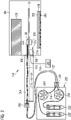
- Figure 2 is a schematic view of the pipetting device 122 of the microscope 100 according to Figure 1 .
- the frame 124 is exemplary shown to be in the operating position, i.e. inside the sample chamber 104.
- a storage chamber 204 for storing the frame 124 in its non-operating position is located to the left of the sample chamber 104 in Figure 2 .
- the storage chamber 204 is spatially separate from the sample chamber 104 and shielded against the environment.
- a wall 206 separates the storage chamber 204 from the sample chamber 104.
- the wall 206 comprises a retraction opening 208 through which the frame 124 can be moved from its operating position to the non-operating position and vice versa.
- the retraction opening 208 can be closed, when the frame 124 is in its non-operating position, in order to shield the sample chamber 104 from the storage chamber 204.
- the movement of the frame 124 takes place along an axis parallel to the top surface 108 of the microscope stage 110 as is indicated in Figure 2 by double-arrows 210.
- the frame 124 is moved by a moving mechanism that comprises a motor 214, for example a linear stepper motor, and guiding rails 216 along which the frame 124 is moved.
- the motor 214 is exemplary arranged on the frame 124 and connected via a flexible cable 218 to a motor controller 220, that provides the motor 214 with energy and control signals.
- the injectors 128 of the frame 124 comprise one or more injector nozzles 222 for introducing a fluid into samples 200.
- the nozzles 222 are arranged on an underside of the injectors 128 facing the sample carrier 106.
- Two fluid lines 224 i.e. one fluid line 224 for each nozzle 222, are connected the injector 128.
- the fluid lines 224 are made from an elastic material such as an elastomer, so they can deform when the injector 128 is moved inside the frame 124 or the frame 124 itself is moved from its operating position to the non-operating position and vice versa.
- the fluid lines 224 can be removed for cleaning or disposal in order to prevent contamination of the samples 200.
- the fluid lines 224 run through the storage chamber 204 to a stopper 226 that is arranged at and end of the storage chamber 204 opposite to the retraction opening 208.
- the fluid lines 224 are guided through the stopper 226 to a fluid reservoir 228 for storing the various fluids to be introduced into the samples 200.
- the fluid reservoir 228 is arranged separate from the sample chamber 104 and the storage chamber 204.
- the fluid lines 224 enter the fluid reservoir 228 through a stopper 230.
- Each fluid line 224 ends in a separate fluid storage tube 232 for storing a single fluid, for example a reagent.
- the fluid storage tubes 232 can be removed from the fluid reservoir 228 in order to refill or exchange the fluid contained therein.
- the fluid storage tubes 232 are formed by disposable plasticware tubes of standardized size. This allows high interoperability with other laboratory equipment and prevents contamination of the fluid.
- the fluid reservoir 228 further comprises pumps 234 for pumping the fluid from its fluid storage tube to one of the nozzles 222.
- the pumps 234 are exemplary formed as peristaltic pumps, further preventing contamination.
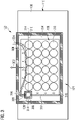
- Figure 3 is a top view of the pipetting device 122 according to Figures 1 and 2 .
- the frame 124 is exemplary shown to be in the operating position, i.e. inside the sample chamber 104.
- the movement of the frame 124 from its operating position to the non-operating position and vice versa takes place along an axis that runs from top to bottom in Figure 3 , as is indicated by a double-arrow 302.
- the injector 128 is arranged in an inside 304 of the frame 124 and can be moved in two orthogonal directions by means of the injector drive 300.
- the injector drive 300 exemplary comprises two linear stepper motors 306, i.e. one for each direction.
- the motors 306 are connected to a flexible cable 308 that runs parallel to the fluid lines 224.
- the flexible cable 308 connects to the motor controller, that provides the motors 306 with energy and control signals.
- the injector drive 300 further comprises two rods 310, 312 on which the injector 128 itself is mounted. Each rod 310, 312 is engaged with two guide rails 314, 316, that face the inside of the frame 124 from opposite sides. Thus, the movement of the injector takes place in a plane defined by the frame 124.
- the inside of the frame 124 is rectangular and dimensioned such that the injector 128 can be positioned above each well 202 of the sample carrier 106 in order to pipet the sample 200 contained therein. Each such position is called a pipetting position.
- the inside of the frame 124 further extends to the left such that the injector 128 can be positioned in an idle position, i.e. a position in which the injector is not above any well 202, as is shown in Figure 2 .
- the sample carrier 106 is exemplary formed as a multi well 202 plate having 24 wells 202 arranged in 4 rows and 6 columns. The rows are labelled A to D and the columns are labelled 1 to 6 in order to uniquely identify each well 202.
- aspects have been described in the context of an apparatus, it is clear that these aspects also represent a description of the corresponding method, where a block or device corresponds to a method step or a feature of a method step. Analogously, aspects described in the context of a method step also represent a description of a corresponding block or item or feature of a corresponding apparatus.
Landscapes
- Physics & Mathematics (AREA)
- Chemical & Material Sciences (AREA)
- General Physics & Mathematics (AREA)
- Analytical Chemistry (AREA)
- Optics & Photonics (AREA)
- Engineering & Computer Science (AREA)
- Health & Medical Sciences (AREA)
- Clinical Laboratory Science (AREA)
- Chemical Kinetics & Catalysis (AREA)
- Multimedia (AREA)
- Theoretical Computer Science (AREA)
- Sampling And Sample Adjustment (AREA)
- Automatic Analysis And Handling Materials Therefor (AREA)
Abstract
Description
- The invention relates to a microscope. Further, the invention relates to a method for examining a sample by means of a microscope.
- Experiments in the life sciences often involve the microscopic study of samples that have been manipulated or treated with various chemicals called reagents in order to study and understand biological processes. These experiments typically involve manual pipetting, e.g. injecting a fluid such as a reagent into a sample. Especially for experiments with a high throughput, for example when using multi well plates, this is a time consuming task. Every necessary human interaction decreases the walk-away time of an experiment, and thus, the efficiency of the experiment. Many experiments also require multiple reagents to be added to the samples in quick succession, while the actual reaction to be observed may take multiple minutes, hours, or even days. While other experiments take place over a very short period of time, for example tracking neuronal activities. Ideally, for this type of experiment, the reagents are introduced and mixed into the sample while image acquisition is taking place.
- Manually pipetting samples is not only tedious and time consuming, it also increases the risk of contaminating the samples. It is therefore desirable to automate the pipetting process as much as possible.
- It is therefore an object to provide a microscope and a method for examining a sample by means of a microscope that allow for automated pipetting.
- The aforementioned object is achieved by the subject-matter of the independent claims. Advantageous embodiments are defined in the dependent claims and the following description.
- The proposed microscope comprises a sample chamber, a microscope stage arranged below the sample chamber configured to have a sample carrier arranged thereon, a pipetting device configured to pipet the sample carrier, and a moving mechanism. The moving mechanism is configured to move the pipetting device between a non-operating position in which the pipetting device is arranged outside the sample chamber and an operating position in which the pipetting device is arranged inside the sample chamber facing the sample carrier.
- Within the context of this document pipetting can mean dropping a fluid onto a sample, injection a sample with a fluid or removing a fluid from a sample or well of a sample carrier.
- The sample or samples are arranged inside the sample chamber, and thereby protected from the environment. In particular, the sample chamber may be formed as a sterile environment protecting the samples from being contaminated. In order to pipet the samples, the pipetting device is brought from outside the sample chamber into the sample chamber by the moving mechanism. No human interaction is required and the pipetting process is easily automated. Thereby, the device can easily be integrated into a workflow design, in particular by means of software such as an experiment designer. The possibility of automation combined with the reduced risk of contamination means the device has a long walk-away time resulting in more efficient experiment designs.
- In a preferred embodiment, the pipetting device comprises at least one movable injector configured to drop or inject a fluid into the sample carrier. Preferably, the injector includes at least one injection nozzle which is arranged to face the sample carrier when the pipetting device is in the operating position. In particular, the movement of the at least one is independent of the movement of the pipetting device between the non-operating position and the operating position. This way, individual pipetting positions, for example single wells of a microwell plate, can be targeted for dropping or injecting the fluid.
- In another preferred embodiment, the pipetting device includes at least one fluid line which is coupled to a fluid reservoir. In particular, the fluid line may be formed from an elastomer. Providing the fluid in the fluid reservoir allows multiple pipetting processes to be performed in succession. This increases the walk-away time of the device even further.
- In another preferred embodiment, the pipetting device comprises a frame on which the at least one injector is mounted. The frame is coupled to the moving mechanism to be moved between the non-operating position and the operating position. Providing a frame for the injector increases the overall stability of the device during movement. This, in turn, allows for faster and more precise pipetting of the samples. Thereby increasing the efficiency and throughput of the device.
- In another preferred embodiment, the pipetting device comprises an injector drive configured to move the injector along at least one direction relatively to the frame to selectively arrange the injector in a plurality of pipetting positions relative to the sample carrier when the frame is in the operating position. In this embodiment, the device has two modes of movement. In a first mode, the whole frame is moved from the non-operating position to the operating position and back. In the second mode, only the injector is moved to any of the pipetting positions in order to pipet the sample located at said pipetting position. By moving only the injector, which typically is much lighter than the whole frame, a very fine control over the injectors position can be achieved.
- In another preferred embodiment, the injector is movable along two orthogonal directions of a rectangular 2D motion grid adapted to the sample carrier. In this embodiment, the injector is arranged movable in two orthogonal direction. This movement is analogous to the movement of an X-Y table. In particular, the injector is movable in a plane which is parallel to a surface of the microscope stage on which the sample carrier is to be arranged. Typically, the individual wells of a microwell plate are arrange in columns and rows. By moving the injector in a rectangular 2D motion grid, individual pipetting positions corresponding to single wells, can be targeted for injecting fluids.
- In another preferred embodiment, the frame has a rectangular shape adapted to the sample carrier. Most sample carriers, with the notable exception of petri dishes, are rectangular. Adapting the geometry of the frame to the geometry of the sample carrier results in an optimized use of construction space inside the microscope.
- In another preferred embodiment, the sample carrier comprises a plurality of sample cavities, each cavity being configured to receive a sample which is to be pipetted by the pipetting device. The sample carrier may for example be a microwell plate. These sample carriers have normed dimensions, meaning that the pipetting positions can be predetermined. In other words, the moving mechanism and the injector drive do not have to be calibrated each experiment. This reduces setup time and increases overall efficiency of the device.
- In another preferred embodiment, the microscope comprises a box-type microscope housing defining the sample chamber above the microscope stage and a storage chamber spatially separated from the sample chamber. The moving mechanism is configured to move the pipetting device, in particular the frame thereof, between the storage chamber and the sample chamber. Box-type microscopes comprise a housing in which all the microscopes components are arranged. The housing typically comprises one or more openings for accessing the inside of the microscope. Due to the enclosed or even sealed nature of the housing, box-type microscopes are especially suited for precisely controlling the environment of the samples, for example by a climate control unit. In this embodiment, both the storage chamber and the sample chamber are located inside the box-type microscope housing. This means, that both the environment of the storage chamber and the sample chamber can be precisely controlled or separated from each other when the pipetting device is not in use.
- In another preferred embodiment, the storage chamber is spatially separated from the sample chamber by a wall comprising a retraction opening through which the pipetting device, in particular the frame thereof, is movable between the storage chamber and the sample chamber. The wall allows the environment of the sample chamber to be controlled independently of the environment of the storage space. The retraction opening forms an airlock that keeps the sample chamber enclosed. This makes the environment of the sample chamber much easier to control.
- In another preferred embodiment, the box-type microscope housing defines a component space below the microscope stage, the component space including a plurality of microscope components. The component space may include a power source of the microscope, an optical imaging system, an illumination system, filters, an environmental control unit.
- In another preferred embodiment, the microscope comprises a stage drive configured to laterally move the microscope stage in a plane which is parallel to the surface of the microscope stage on which the sample carrier is to be arranged. In particular, the plane of movement of the microscope stage is parallel to a plane in which the injector is moved. Thereby, the distance between the injector and the sample carrier is the same for all pipetting positions and positions of the microscope stage. This allows for precise pipetting.
- In another preferred embodiment, the microscope comprises a controller configured to synchronize a pipetting operation and an imaging operation. The controller may for example be a processor that is arranged inside the microscope itself or an external device such as a PC that is connected to the microscope. The controller allows the microscope to work autonomously and to be integrated into an automated workflow. Thereby, the walk-away time and thus the efficiency of the microscope are further increased.
- The invention also relates to a method for examining a sample by mean of a microscope. The proposed method comprises the following steps: Moving the pipetting device from the non-operating position in a storage chamber outside a sample chamber of the microscope into the operating position inside the sample chamber to arrange the pipetting device facing the sample carrier. Pipetting the sample carrier by means of the pipetting device. Moving the pipetting device from the operating position into the non-operating position to arrange the pipetting device remote from the sample carrier. Imaging the sample.
- The method has the same advantages as the microscope described above and can be supplemented using the features of the dependent claims directed at the microscope.
- Hereinafter, specific embodiments are described referring to the drawings, wherein:
- Figure 1
- is a schematic view of a microscope;
- Figure 2
- is schematic view of a pipetting device of the microscope according to
Figure 1 ; and - Figure 3
- is a top view of the pipetting device according to
Figures 1 and2 . -
Figure 1 is a schematic view of amicroscope 100. Themicroscope 100 is exemplary formed as a box-type microscope. - Conventional microscopes comprise a microscope stand which holds all microscope components. The open nature of the conventional microscope allows easy access to all its components. However, due to the open nature samples arranged on a conventional microscope are exposed to the environment. Further, the microscope stand typically blocks access to the sample from one side.
- In contrast thereto, box-
type microscope 100 shown inFigure 1 is completely enclosed inside amicroscope housing 102. In particular, themicroscope housing 102 forms asample chamber 104 for receiving one or more samples 200 (c.f.Figure 2 ). By enclosing thesamples 200, a precise control over the samples' 200 environment is possible, for example via a climate control unit for controlling temperature and humidity of thesample chamber 104. Theenclosed samples 200 are also shielded against the environment, and thus protected against accidental contamination. Further, thesample chamber 104 can easily be made into an incubation chamber and/or a sterile environment, if an experiments demands it. - The
samples 200 are arranged in asample carrier 106, for example a microwell plate or a microscope slide.Sample carriers 106 such as a microwell plate typically comprise a number of individual cavities or wells 202 (c.f.Figure 2 ) for arranging thesamples 200, while a microscope slide typically holds an individual sample. Thesample carrier 106 is positioned on atop surface 108 of amicroscope stage 110, that is arranged below thesample chamber 104. Themicroscope stage 110 is movable along two orthogonal directions, i.e. themicroscope stage 110 is a so called X-Y-table. This is indicated inFigure 1 by two double-arrows microscope stage 110 allows for example for selectingindividual cavity 202 of thesample carrier 106 or selecting a specific region of interest of asingle sample 200 for observation. - The
microscope 100 according toFigure 1 is exemplary formed as a transmitted light microscope.Imaging optics 116 for imaging thesamples 200 are exemplary arranged below themicroscope stage 110 in acomponent space 118 and anillumination system 120 for illuminating thesamples 200 is arranged above themicroscope stage 110 inside thesample chamber 104. The optical axis of theimaging optics 116 and the optical axis of theillumination system 120 are aligned. Thereby, illumination light emitted by theillumination system 120 passes through thesamples 200 before entering theimaging optics 116. In an alternative embodiment, the positions of theimaging optics 116 and theillumination system 120 may be reversed. In another alternative embodiment, both theimaging system 116 and theillumination system 120 are arranged on the same side of themicroscope stage 110. Additional components such as a power source of various filters may be arranged in the component space - The
microscope 100 further comprises apipetting device 122 for pipetting thesamples 200, for example introducing various liquid reagents into thesamples 200. Thepipetting device 122 comprises arectangular frame 124 that is of similar size and dimension as thesample carrier 106. Theframe 124 is arranged parallel to thetop surface 108 of themicroscope stage 110 and is moveable along one direction from non-operating position to an operating position and back. The movement of theframe 124 is indicated inFigure 1 by a double-arrow 126. The direction of movement is exemplary show to be parallel to thetop surface 108 of themicroscope stage 110. The non-operating position of theframe 124 is outside thesample chamber 104, for example inside a storage chamber (c.f.Figure 2 ), while the operating position of theframe 124 is inside thesample chamber 104. - The
frame 124 holds one ormore injectors 128, of which only oneinjector 128 is shown inFigure 1 . Theinjectors 128 are moveable inside theframe 124 by means of an injector drive 300 (c.f.Figure 3 ). Thus, theinjectors 128 can targetindividual wells 202 of thesample carrier 106 for pipetting. Thepipetting device 122 is described in further detail below with reference toFigures 2 and3 . -
Figure 2 is a schematic view of thepipetting device 122 of themicroscope 100 according toFigure 1 . InFigure 2 , theframe 124 is exemplary shown to be in the operating position, i.e. inside thesample chamber 104. - A
storage chamber 204 for storing theframe 124 in its non-operating position is located to the left of thesample chamber 104 inFigure 2 . Thestorage chamber 204 is spatially separate from thesample chamber 104 and shielded against the environment. Awall 206 separates thestorage chamber 204 from thesample chamber 104. Thewall 206 comprises aretraction opening 208 through which theframe 124 can be moved from its operating position to the non-operating position and vice versa. Theretraction opening 208 can be closed, when theframe 124 is in its non-operating position, in order to shield thesample chamber 104 from thestorage chamber 204. - The movement of the
frame 124 takes place along an axis parallel to thetop surface 108 of themicroscope stage 110 as is indicated inFigure 2 by double-arrows 210. Theframe 124 is moved by a moving mechanism that comprises amotor 214, for example a linear stepper motor, and guidingrails 216 along which theframe 124 is moved. Themotor 214 is exemplary arranged on theframe 124 and connected via aflexible cable 218 to amotor controller 220, that provides themotor 214 with energy and control signals. - As can be seen in
Figure 2 , theinjectors 128 of theframe 124 comprise one or more injector nozzles 222 for introducing a fluid intosamples 200. The nozzles 222 are arranged on an underside of theinjectors 128 facing thesample carrier 106. Twofluid lines 224, i.e. onefluid line 224 for each nozzle 222, are connected theinjector 128. Thefluid lines 224 are made from an elastic material such as an elastomer, so they can deform when theinjector 128 is moved inside theframe 124 or theframe 124 itself is moved from its operating position to the non-operating position and vice versa. In particular, thefluid lines 224 can be removed for cleaning or disposal in order to prevent contamination of thesamples 200. Thefluid lines 224 run through thestorage chamber 204 to astopper 226 that is arranged at and end of thestorage chamber 204 opposite to theretraction opening 208. Thefluid lines 224 are guided through thestopper 226 to afluid reservoir 228 for storing the various fluids to be introduced into thesamples 200. - The
fluid reservoir 228 is arranged separate from thesample chamber 104 and thestorage chamber 204. Thefluid lines 224 enter thefluid reservoir 228 through astopper 230. Eachfluid line 224 ends in a separatefluid storage tube 232 for storing a single fluid, for example a reagent. Thefluid storage tubes 232 can be removed from thefluid reservoir 228 in order to refill or exchange the fluid contained therein. In particular, thefluid storage tubes 232 are formed by disposable plasticware tubes of standardized size. This allows high interoperability with other laboratory equipment and prevents contamination of the fluid. Thefluid reservoir 228 further comprisespumps 234 for pumping the fluid from its fluid storage tube to one of the nozzles 222. Thepumps 234 are exemplary formed as peristaltic pumps, further preventing contamination. -
Figure 3 is a top view of thepipetting device 122 according toFigures 1 and2 . InFigure 3 , theframe 124 is exemplary shown to be in the operating position, i.e. inside thesample chamber 104. The movement of theframe 124 from its operating position to the non-operating position and vice versa takes place along an axis that runs from top to bottom inFigure 3 , as is indicated by a double-arrow 302. - The
injector 128 is arranged in an inside 304 of theframe 124 and can be moved in two orthogonal directions by means of theinjector drive 300. The injector drive 300 exemplary comprises twolinear stepper motors 306, i.e. one for each direction. Themotors 306 are connected to aflexible cable 308 that runs parallel to the fluid lines 224. Theflexible cable 308 connects to the motor controller, that provides themotors 306 with energy and control signals. Theinjector drive 300 further comprises tworods injector 128 itself is mounted. Eachrod guide rails frame 124 from opposite sides. Thus, the movement of the injector takes place in a plane defined by theframe 124. - The inside of the
frame 124 is rectangular and dimensioned such that theinjector 128 can be positioned above each well 202 of thesample carrier 106 in order to pipet thesample 200 contained therein. Each such position is called a pipetting position. The inside of theframe 124 further extends to the left such that theinjector 128 can be positioned in an idle position, i.e. a position in which the injector is not above any well 202, as is shown inFigure 2 . - The
sample carrier 106 is exemplary formed as amulti well 202 plate having 24wells 202 arranged in 4 rows and 6 columns. The rows are labelled A to D and the columns are labelled 1 to 6 in order to uniquely identify each well 202. - Identical or similarly acting elements are designated with the same reference signs in
Figures 1 to 3 . As used herein the term "and/or" includes any and all combinations of one or more of the associated listed items and may be abbreviated as "/". - Although some aspects have been described in the context of an apparatus, it is clear that these aspects also represent a description of the corresponding method, where a block or device corresponds to a method step or a feature of a method step. Analogously, aspects described in the context of a method step also represent a description of a corresponding block or item or feature of a corresponding apparatus.
-
- 100
- Microscope
- 102
- Housing
- 104
- Sample chamber
- 106
- Sample carrier
- 108
- Surface
- 110
- Microscope stage
- 112,114
- Arrows
- 116
- Imaging system
- 118
- Component space
- 120
- Illumination system
- 122
- Pipetting device
- 124
- Frame
- 126
- Arrow
- 128
- Injector
- 200
- Sample
- 202
- Well
- 204
- Storage chamber
- 206
- Wall
- 208
- Opening
- 210
- Arrow
- 212
- Moving mechanism
- 214
- Motor
- 216
- Rails
- 218
- Cable
- 220
- Controller
- 222
- Nozzle
- 224
- Fluid line
- 226
- Stopper
- 228
- Fluid reservoir
- 230
- Stopper
- 232
- Fluid storage tubes
- 234
- Pump
- 300
- Injector drive
- 302
- Arrow
- 304
- Inside
- 306
- Motor
- 308
- Cable
Claims (15)
- A microscope (100), comprising:a sample chamber (104),a microscope stage (110) arranged below the sample chamber (104) configured to have a sample carrier (106) arranged thereon,a pipetting device (122) configured to pipet the sample carrier (106), anda moving mechanism configured to move the pipetting device (122) between a non-operating position in which the pipetting device (122) is arranged outside the sample chamber (104) sample carrier (106) and an operating position in which the pipetting device (122) is arranged inside the sample chamber (104) facing the sample carrier (106).
- The microscope (100) according to claim 1, wherein the pipetting device (122) comprises at least one movable injector configured to drop or inject fluid into the sample carrier (106).
- The microscope (100) according to claim 2, wherein the injector includes at least one injection nozzle (222) which is arranged to face the sample carrier (106) when the pipetting device (122) is in the operating position.
- The microscope (100) according to one of the preceding claims, wherein the pipetting device (122) includes at least one fluid line which is coupled to a fluid reservoir (228).
- The microscope (100) according to one of the claims 2 to 4, wherein the pipetting device (122) comprises a frame (124) on which the at least one injector is mounted,
the frame (124) being coupled to the moving mechanism to be moved between the non-operating position and the operating position. - The microscope (100) according to claim 5, wherein the pipetting device (122) comprises an injector drive (300) configured to move the injector along at least one direction relatively to the frame (124) to selectively arrange the injector in a plurality of pipetting positions relative to the sample carrier (106) when the frame (124) is in the operating position.
- The microscope (100) according to one of the claims 2 to 6, wherein the injector is movable along two orthogonal directions of a rectangular 2D motion grid adapted to the sample carrier (106).
- The microscope (100) according to one of the claims 5 to 7, wherein the frame (124) has a rectangular shape adapted to the sample carrier (106).
- The microscope (100) according to one of the preceding claims, wherein the sample carrier (106) comprises a plurality of sample cavities, each cavity (202) being configured to receive a sample which is to be pipetted by the pipetting device (122).
- The microscope (100) according to one of the preceding claims, comprising a box-type microscope housing (102) defining the sample chamber above the microscope stage (110) and a storage chamber (204) spatially separated from the sample chamber,
wherein the moving mechanism is configured to move the pipetting device (122) between the storage chamber (204) and the sample chamber (104). - The microscope (100) according to claim 10, wherein the storage chamber (204) is spatially separated from the sample chamber by a wall comprising a retraction opening through which the pipetting device (122) is movable between the storage chamber (204) and the sample chamber.
- The microscope (100) according to claim 10 or 11, wherein the box-type microscope housing (102) defines a component space below the microscope stage (110), the component space including a plurality of microscope (100) components.
- The microscope (100) according to one of the preceding claims, comprising a stage drive configured to laterally move the microscope stage (110) in a plane which is parallel to a surface of the microscope stage (110) on which the sample carrier (106) is to be arranged.
- The microscope (100) according to one of the preceding claims, comprising a controller configured to synchronize a pipetting operation and an imaging operation.
- A method for examining a sample (200) by means of the microscope (100) according to one of the preceding claims, comprising following steps:moving the pipetting device (122) from the non-operating position in a storage chamber (204) outside a sample chamber (104) of the microscope (100) storage chamber (204) into the operating position inside the sample chamber (104) to arrange the pipetting device (122) facing the sample carrier (106),pipetting the sample carrier (106) by means of the pipetting device (122),moving the pipetting device (122) from the operating position into the non-operating position to arrange the pipetting device (122) remote from the sample carrier (106), andimaging the sample (200).
Priority Applications (3)
| Application Number | Priority Date | Filing Date | Title |
|---|---|---|---|
| EP21179092.8A EP4102285B1 (en) | 2021-06-11 | 2021-06-11 | Microscope and method for examining a sample |
| US17/829,392 US12416797B2 (en) | 2021-06-11 | 2022-06-01 | Microscope and method for examining a sample |
| CN202210651862.5A CN115463701A (en) | 2021-06-11 | 2022-06-10 | Microscope and method for examining a sample |
Applications Claiming Priority (1)
| Application Number | Priority Date | Filing Date | Title |
|---|---|---|---|
| EP21179092.8A EP4102285B1 (en) | 2021-06-11 | 2021-06-11 | Microscope and method for examining a sample |
Publications (2)
| Publication Number | Publication Date |
|---|---|
| EP4102285A1 true EP4102285A1 (en) | 2022-12-14 |
| EP4102285B1 EP4102285B1 (en) | 2025-06-04 |
Family
ID=76444240
Family Applications (1)
| Application Number | Title | Priority Date | Filing Date |
|---|---|---|---|
| EP21179092.8A Active EP4102285B1 (en) | 2021-06-11 | 2021-06-11 | Microscope and method for examining a sample |
Country Status (3)
| Country | Link |
|---|---|
| US (1) | US12416797B2 (en) |
| EP (1) | EP4102285B1 (en) |
| CN (1) | CN115463701A (en) |
Families Citing this family (1)
| Publication number | Priority date | Publication date | Assignee | Title |
|---|---|---|---|---|
| EP4733824A3 (en) * | 2024-03-12 | 2026-05-13 | Leica Microsystems CMS GmbH | Microscope stage and method for examining a sample |
Citations (2)
| Publication number | Priority date | Publication date | Assignee | Title |
|---|---|---|---|---|
| US20170022537A1 (en) * | 2015-07-24 | 2017-01-26 | Molecular Devices, Llc | Luminescence measurement of biologial samples utilizing dual reagents |
| US20180128676A1 (en) * | 2016-11-07 | 2018-05-10 | Molecular Devices (Austria) GmbH | System for optically monitoring operating conditions in a sample analyzing apparatus |
Family Cites Families (1)
| Publication number | Priority date | Publication date | Assignee | Title |
|---|---|---|---|---|
| JP4474859B2 (en) * | 2003-07-15 | 2010-06-09 | 株式会社ニコン | Microscope with dispenser |
-
2021
- 2021-06-11 EP EP21179092.8A patent/EP4102285B1/en active Active
-
2022
- 2022-06-01 US US17/829,392 patent/US12416797B2/en active Active
- 2022-06-10 CN CN202210651862.5A patent/CN115463701A/en active Pending
Patent Citations (2)
| Publication number | Priority date | Publication date | Assignee | Title |
|---|---|---|---|---|
| US20170022537A1 (en) * | 2015-07-24 | 2017-01-26 | Molecular Devices, Llc | Luminescence measurement of biologial samples utilizing dual reagents |
| US20180128676A1 (en) * | 2016-11-07 | 2018-05-10 | Molecular Devices (Austria) GmbH | System for optically monitoring operating conditions in a sample analyzing apparatus |
Also Published As
| Publication number | Publication date |
|---|---|
| US20220397753A1 (en) | 2022-12-15 |
| CN115463701A (en) | 2022-12-13 |
| US12416797B2 (en) | 2025-09-16 |
| EP4102285B1 (en) | 2025-06-04 |
Similar Documents
| Publication | Publication Date | Title |
|---|---|---|
| US12066373B2 (en) | System and method for retrieving and analyzing particles | |
| EP3597728B1 (en) | Cell transfer device and cell transfer method | |
| US7541001B2 (en) | Automatic pipetting and analyzing device | |
| US10399048B2 (en) | Sample processing apparatus with integrated heater, shaker and magnet | |
| CN112384809B (en) | Fluid automatic samplers and incubators | |
| US20090042281A1 (en) | Compound profiling devices, systems, and related methods | |
| US20220074960A1 (en) | Sample pretreatment device, analysis system including the device, and autosampler | |
| US12416797B2 (en) | Microscope and method for examining a sample | |
| EP3326719B1 (en) | Flow cell assembly securement system and method | |
| WO2017087698A1 (en) | Incubator insert for automated culture experimentation | |
| US20230086623A1 (en) | Microscope system and method for imaging a sample | |
| US10591501B2 (en) | Automatic structure determination | |
| EP1231472B1 (en) | Integrated fluid delivery and analysis system | |
| US20240060892A1 (en) | Imaging device | |
| WO2022069878A1 (en) | Cell deposition and imaging apparatus | |
| EP4160217B1 (en) | Nucleic acid analysis device | |
| EP4617639A1 (en) | Microscope stage, replaceable fluidic link and method for examining a sample | |
| EP4198603A1 (en) | Microscope | |
| Speier | Concept study of an Epifuorescence Microscope for Live-Cell Imaging in Microgravity on Sounding Rockets | |
| KR20260017410A (en) | Extraction equipment for samples | |
| CN118109289A (en) | Method for cell tracking, cell observation and cell micromanipulation in microfluidic chip | |
| KR20250164038A (en) | apparatus for preprocessing molecular diagnostics having under cover for syringe tip | |
| CN121569021A (en) | Cell culture apparatus and cell culture method | |
| Blaylock | A Bio-Assembly, Mosaic Building, and Informatics System for Cell Biology |
Legal Events
| Date | Code | Title | Description |
|---|---|---|---|
| PUAI | Public reference made under article 153(3) epc to a published international application that has entered the european phase |
Free format text: ORIGINAL CODE: 0009012 |
|
| STAA | Information on the status of an ep patent application or granted ep patent |
Free format text: STATUS: THE APPLICATION HAS BEEN PUBLISHED |
|
| AK | Designated contracting states |
Kind code of ref document: A1 Designated state(s): AL AT BE BG CH CY CZ DE DK EE ES FI FR GB GR HR HU IE IS IT LI LT LU LV MC MK MT NL NO PL PT RO RS SE SI SK SM TR |
|
| P01 | Opt-out of the competence of the unified patent court (upc) registered |
Effective date: 20230414 |
|
| STAA | Information on the status of an ep patent application or granted ep patent |
Free format text: STATUS: REQUEST FOR EXAMINATION WAS MADE |
|
| 17P | Request for examination filed |
Effective date: 20230612 |
|
| RBV | Designated contracting states (corrected) |
Designated state(s): AL AT BE BG CH CY CZ DE DK EE ES FI FR GB GR HR HU IE IS IT LI LT LU LV MC MK MT NL NO PL PT RO RS SE SI SK SM TR |
|
| GRAP | Despatch of communication of intention to grant a patent |
Free format text: ORIGINAL CODE: EPIDOSNIGR1 |
|
| STAA | Information on the status of an ep patent application or granted ep patent |
Free format text: STATUS: GRANT OF PATENT IS INTENDED |
|
| INTG | Intention to grant announced |
Effective date: 20250110 |
|
| GRAS | Grant fee paid |
Free format text: ORIGINAL CODE: EPIDOSNIGR3 |
|
| GRAA | (expected) grant |
Free format text: ORIGINAL CODE: 0009210 |
|
| STAA | Information on the status of an ep patent application or granted ep patent |
Free format text: STATUS: THE PATENT HAS BEEN GRANTED |
|
| AK | Designated contracting states |
Kind code of ref document: B1 Designated state(s): AL AT BE BG CH CY CZ DE DK EE ES FI FR GB GR HR HU IE IS IT LI LT LU LV MC MK MT NL NO PL PT RO RS SE SI SK SM TR |
|
| REG | Reference to a national code |
Ref country code: GB Ref legal event code: FG4D |
|
| REG | Reference to a national code |
Ref country code: CH Ref legal event code: EP |
|
| REG | Reference to a national code |
Ref country code: DE Ref legal event code: R096 Ref document number: 602021031632 Country of ref document: DE |
|
| REG | Reference to a national code |
Ref country code: IE Ref legal event code: FG4D |
|
| PGFP | Annual fee paid to national office [announced via postgrant information from national office to epo] |
Ref country code: DE Payment date: 20250626 Year of fee payment: 5 |
|
| PGFP | Annual fee paid to national office [announced via postgrant information from national office to epo] |
Ref country code: GB Payment date: 20250617 Year of fee payment: 5 |
|
| PGFP | Annual fee paid to national office [announced via postgrant information from national office to epo] |
Ref country code: FR Payment date: 20250624 Year of fee payment: 5 |
|
| PGFP | Annual fee paid to national office [announced via postgrant information from national office to epo] |
Ref country code: AT Payment date: 20250721 Year of fee payment: 5 |
|
| REG | Reference to a national code |
Ref country code: NL Ref legal event code: MP Effective date: 20250604 |
|
| PG25 | Lapsed in a contracting state [announced via postgrant information from national office to epo] |
Ref country code: ES Free format text: LAPSE BECAUSE OF FAILURE TO SUBMIT A TRANSLATION OF THE DESCRIPTION OR TO PAY THE FEE WITHIN THE PRESCRIBED TIME-LIMIT Effective date: 20250604 Ref country code: FI Free format text: LAPSE BECAUSE OF FAILURE TO SUBMIT A TRANSLATION OF THE DESCRIPTION OR TO PAY THE FEE WITHIN THE PRESCRIBED TIME-LIMIT Effective date: 20250604 |
|
| REG | Reference to a national code |
Ref country code: LT Ref legal event code: MG9D |
|
| PG25 | Lapsed in a contracting state [announced via postgrant information from national office to epo] |
Ref country code: NO Free format text: LAPSE BECAUSE OF FAILURE TO SUBMIT A TRANSLATION OF THE DESCRIPTION OR TO PAY THE FEE WITHIN THE PRESCRIBED TIME-LIMIT Effective date: 20250904 Ref country code: GR Free format text: LAPSE BECAUSE OF FAILURE TO SUBMIT A TRANSLATION OF THE DESCRIPTION OR TO PAY THE FEE WITHIN THE PRESCRIBED TIME-LIMIT Effective date: 20250905 |
|
| PG25 | Lapsed in a contracting state [announced via postgrant information from national office to epo] |
Ref country code: PL Free format text: LAPSE BECAUSE OF FAILURE TO SUBMIT A TRANSLATION OF THE DESCRIPTION OR TO PAY THE FEE WITHIN THE PRESCRIBED TIME-LIMIT Effective date: 20250604 |
|
| PG25 | Lapsed in a contracting state [announced via postgrant information from national office to epo] |
Ref country code: BG Free format text: LAPSE BECAUSE OF FAILURE TO SUBMIT A TRANSLATION OF THE DESCRIPTION OR TO PAY THE FEE WITHIN THE PRESCRIBED TIME-LIMIT Effective date: 20250604 |
|
| PG25 | Lapsed in a contracting state [announced via postgrant information from national office to epo] |
Ref country code: HR Free format text: LAPSE BECAUSE OF FAILURE TO SUBMIT A TRANSLATION OF THE DESCRIPTION OR TO PAY THE FEE WITHIN THE PRESCRIBED TIME-LIMIT Effective date: 20250604 |
|
| PG25 | Lapsed in a contracting state [announced via postgrant information from national office to epo] |
Ref country code: RS Free format text: LAPSE BECAUSE OF FAILURE TO SUBMIT A TRANSLATION OF THE DESCRIPTION OR TO PAY THE FEE WITHIN THE PRESCRIBED TIME-LIMIT Effective date: 20250904 |
|
| PG25 | Lapsed in a contracting state [announced via postgrant information from national office to epo] |
Ref country code: LV Free format text: LAPSE BECAUSE OF FAILURE TO SUBMIT A TRANSLATION OF THE DESCRIPTION OR TO PAY THE FEE WITHIN THE PRESCRIBED TIME-LIMIT Effective date: 20250604 |
|
| PG25 | Lapsed in a contracting state [announced via postgrant information from national office to epo] |
Ref country code: NL Free format text: LAPSE BECAUSE OF FAILURE TO SUBMIT A TRANSLATION OF THE DESCRIPTION OR TO PAY THE FEE WITHIN THE PRESCRIBED TIME-LIMIT Effective date: 20250604 |
|
| PG25 | Lapsed in a contracting state [announced via postgrant information from national office to epo] |
Ref country code: PT Free format text: LAPSE BECAUSE OF FAILURE TO SUBMIT A TRANSLATION OF THE DESCRIPTION OR TO PAY THE FEE WITHIN THE PRESCRIBED TIME-LIMIT Effective date: 20251006 |
|
| REG | Reference to a national code |
Ref country code: AT Ref legal event code: MK05 Ref document number: 1800865 Country of ref document: AT Kind code of ref document: T Effective date: 20250604 |
|
| PG25 | Lapsed in a contracting state [announced via postgrant information from national office to epo] |
Ref country code: IS Free format text: LAPSE BECAUSE OF FAILURE TO SUBMIT A TRANSLATION OF THE DESCRIPTION OR TO PAY THE FEE WITHIN THE PRESCRIBED TIME-LIMIT Effective date: 20251004 |
|
| PG25 | Lapsed in a contracting state [announced via postgrant information from national office to epo] |
Ref country code: AT Free format text: LAPSE BECAUSE OF FAILURE TO SUBMIT A TRANSLATION OF THE DESCRIPTION OR TO PAY THE FEE WITHIN THE PRESCRIBED TIME-LIMIT Effective date: 20250604 Ref country code: SM Free format text: LAPSE BECAUSE OF FAILURE TO SUBMIT A TRANSLATION OF THE DESCRIPTION OR TO PAY THE FEE WITHIN THE PRESCRIBED TIME-LIMIT Effective date: 20250604 |
|
| PG25 | Lapsed in a contracting state [announced via postgrant information from national office to epo] |
Ref country code: CZ Free format text: LAPSE BECAUSE OF FAILURE TO SUBMIT A TRANSLATION OF THE DESCRIPTION OR TO PAY THE FEE WITHIN THE PRESCRIBED TIME-LIMIT Effective date: 20250604 |
|
| PG25 | Lapsed in a contracting state [announced via postgrant information from national office to epo] |
Ref country code: EE Free format text: LAPSE BECAUSE OF FAILURE TO SUBMIT A TRANSLATION OF THE DESCRIPTION OR TO PAY THE FEE WITHIN THE PRESCRIBED TIME-LIMIT Effective date: 20250604 |
|
| PG25 | Lapsed in a contracting state [announced via postgrant information from national office to epo] |
Ref country code: SK Free format text: LAPSE BECAUSE OF FAILURE TO SUBMIT A TRANSLATION OF THE DESCRIPTION OR TO PAY THE FEE WITHIN THE PRESCRIBED TIME-LIMIT Effective date: 20250604 |
|
| REG | Reference to a national code |
Ref country code: CH Ref legal event code: H13 Free format text: ST27 STATUS EVENT CODE: U-0-0-H10-H13 (AS PROVIDED BY THE NATIONAL OFFICE) Effective date: 20260127 |
|
| PG25 | Lapsed in a contracting state [announced via postgrant information from national office to epo] |
Ref country code: IT Free format text: LAPSE BECAUSE OF FAILURE TO SUBMIT A TRANSLATION OF THE DESCRIPTION OR TO PAY THE FEE WITHIN THE PRESCRIBED TIME-LIMIT Effective date: 20250604 |
|
| PG25 | Lapsed in a contracting state [announced via postgrant information from national office to epo] |
Ref country code: RO Free format text: LAPSE BECAUSE OF FAILURE TO SUBMIT A TRANSLATION OF THE DESCRIPTION OR TO PAY THE FEE WITHIN THE PRESCRIBED TIME-LIMIT Effective date: 20250604 |
|
| PG25 | Lapsed in a contracting state [announced via postgrant information from national office to epo] |
Ref country code: LU Free format text: LAPSE BECAUSE OF NON-PAYMENT OF DUE FEES Effective date: 20250611 |
|
| REG | Reference to a national code |
Ref country code: BE Ref legal event code: MM Effective date: 20250630 |
|
| REG | Reference to a national code |
Ref country code: DE Ref legal event code: R097 Ref document number: 602021031632 Country of ref document: DE |
|
| PG25 | Lapsed in a contracting state [announced via postgrant information from national office to epo] |
Ref country code: MC Free format text: LAPSE BECAUSE OF FAILURE TO SUBMIT A TRANSLATION OF THE DESCRIPTION OR TO PAY THE FEE WITHIN THE PRESCRIBED TIME-LIMIT Effective date: 20250604 |
|
| PLBE | No opposition filed within time limit |
Free format text: ORIGINAL CODE: 0009261 |
|
| STAA | Information on the status of an ep patent application or granted ep patent |
Free format text: STATUS: NO OPPOSITION FILED WITHIN TIME LIMIT |
|
| PG25 | Lapsed in a contracting state [announced via postgrant information from national office to epo] |
Ref country code: IE Free format text: LAPSE BECAUSE OF NON-PAYMENT OF DUE FEES Effective date: 20250611 Ref country code: DK Free format text: LAPSE BECAUSE OF FAILURE TO SUBMIT A TRANSLATION OF THE DESCRIPTION OR TO PAY THE FEE WITHIN THE PRESCRIBED TIME-LIMIT Effective date: 20250604 |
|
| PG25 | Lapsed in a contracting state [announced via postgrant information from national office to epo] |
Ref country code: BE Free format text: LAPSE BECAUSE OF NON-PAYMENT OF DUE FEES Effective date: 20250630 |
|
| REG | Reference to a national code |
Ref country code: CH Ref legal event code: L10 Free format text: ST27 STATUS EVENT CODE: U-0-0-L10-L00 (AS PROVIDED BY THE NATIONAL OFFICE) Effective date: 20260416 |
|
| PG25 | Lapsed in a contracting state [announced via postgrant information from national office to epo] |
Ref country code: CH Free format text: LAPSE BECAUSE OF NON-PAYMENT OF DUE FEES Effective date: 20250630 |
|
| 26N | No opposition filed |
Effective date: 20260305 |