EP4102111A1 - Sliding component - Google Patents
Sliding component Download PDFInfo
- Publication number
- EP4102111A1 EP4102111A1 EP20929917.1A EP20929917A EP4102111A1 EP 4102111 A1 EP4102111 A1 EP 4102111A1 EP 20929917 A EP20929917 A EP 20929917A EP 4102111 A1 EP4102111 A1 EP 4102111A1
- Authority
- EP
- European Patent Office
- Prior art keywords
- dimple
- dimples
- dimple group
- sliding
- curve
- Prior art date
- Legal status (The legal status is an assumption and is not a legal conclusion. Google has not performed a legal analysis and makes no representation as to the accuracy of the status listed.)
- Pending
Links
Images




Classifications
-
- F—MECHANICAL ENGINEERING; LIGHTING; HEATING; WEAPONS; BLASTING
- F16—ENGINEERING ELEMENTS AND UNITS; GENERAL MEASURES FOR PRODUCING AND MAINTAINING EFFECTIVE FUNCTIONING OF MACHINES OR INSTALLATIONS; THERMAL INSULATION IN GENERAL
- F16J—PISTONS; CYLINDERS; SEALINGS
- F16J15/00—Sealings
- F16J15/16—Sealings between relatively-moving surfaces
- F16J15/34—Sealings between relatively-moving surfaces with slip-ring pressed against a more or less radial face on one member
- F16J15/3404—Sealings between relatively-moving surfaces with slip-ring pressed against a more or less radial face on one member and characterised by parts or details relating to lubrication, cooling or venting of the seal
- F16J15/3408—Sealings between relatively-moving surfaces with slip-ring pressed against a more or less radial face on one member and characterised by parts or details relating to lubrication, cooling or venting of the seal at least one ring having an uneven slipping surface
- F16J15/3424—Sealings between relatively-moving surfaces with slip-ring pressed against a more or less radial face on one member and characterised by parts or details relating to lubrication, cooling or venting of the seal at least one ring having an uneven slipping surface with microcavities
-
- F—MECHANICAL ENGINEERING; LIGHTING; HEATING; WEAPONS; BLASTING
- F16—ENGINEERING ELEMENTS AND UNITS; GENERAL MEASURES FOR PRODUCING AND MAINTAINING EFFECTIVE FUNCTIONING OF MACHINES OR INSTALLATIONS; THERMAL INSULATION IN GENERAL
- F16J—PISTONS; CYLINDERS; SEALINGS
- F16J15/00—Sealings
- F16J15/16—Sealings between relatively-moving surfaces
- F16J15/34—Sealings between relatively-moving surfaces with slip-ring pressed against a more or less radial face on one member
- F16J15/3404—Sealings between relatively-moving surfaces with slip-ring pressed against a more or less radial face on one member and characterised by parts or details relating to lubrication, cooling or venting of the seal
- F16J15/3408—Sealings between relatively-moving surfaces with slip-ring pressed against a more or less radial face on one member and characterised by parts or details relating to lubrication, cooling or venting of the seal at least one ring having an uneven slipping surface
- F16J15/3412—Sealings between relatively-moving surfaces with slip-ring pressed against a more or less radial face on one member and characterised by parts or details relating to lubrication, cooling or venting of the seal at least one ring having an uneven slipping surface with cavities
-
- F—MECHANICAL ENGINEERING; LIGHTING; HEATING; WEAPONS; BLASTING
- F16—ENGINEERING ELEMENTS AND UNITS; GENERAL MEASURES FOR PRODUCING AND MAINTAINING EFFECTIVE FUNCTIONING OF MACHINES OR INSTALLATIONS; THERMAL INSULATION IN GENERAL
- F16C—SHAFTS; FLEXIBLE SHAFTS; ELEMENTS OR CRANKSHAFT MECHANISMS; ROTARY BODIES OTHER THAN GEARING ELEMENTS; BEARINGS
- F16C17/00—Sliding-contact bearings for exclusively rotary movement
- F16C17/04—Sliding-contact bearings for exclusively rotary movement for axial load only
- F16C17/045—Sliding-contact bearings for exclusively rotary movement for axial load only with grooves in the bearing surface to generate hydrodynamic pressure, e.g. spiral groove thrust bearings
-
- F—MECHANICAL ENGINEERING; LIGHTING; HEATING; WEAPONS; BLASTING
- F16—ENGINEERING ELEMENTS AND UNITS; GENERAL MEASURES FOR PRODUCING AND MAINTAINING EFFECTIVE FUNCTIONING OF MACHINES OR INSTALLATIONS; THERMAL INSULATION IN GENERAL
- F16C—SHAFTS; FLEXIBLE SHAFTS; ELEMENTS OR CRANKSHAFT MECHANISMS; ROTARY BODIES OTHER THAN GEARING ELEMENTS; BEARINGS
- F16C33/00—Parts of bearings; Special methods for making bearings or parts thereof
- F16C33/02—Parts of sliding-contact bearings
- F16C33/04—Brasses; Bushes; Linings
- F16C33/06—Sliding surface mainly made of metal
- F16C33/10—Construction relative to lubrication
- F16C33/1025—Construction relative to lubrication with liquid, e.g. oil, as lubricant
- F16C33/106—Details of distribution or circulation inside the bearings, e.g. details of the bearing surfaces to affect flow or pressure of the liquid
- F16C33/1065—Grooves on a bearing surface for distributing or collecting the liquid
-
- F—MECHANICAL ENGINEERING; LIGHTING; HEATING; WEAPONS; BLASTING
- F16—ENGINEERING ELEMENTS AND UNITS; GENERAL MEASURES FOR PRODUCING AND MAINTAINING EFFECTIVE FUNCTIONING OF MACHINES OR INSTALLATIONS; THERMAL INSULATION IN GENERAL
- F16C—SHAFTS; FLEXIBLE SHAFTS; ELEMENTS OR CRANKSHAFT MECHANISMS; ROTARY BODIES OTHER THAN GEARING ELEMENTS; BEARINGS
- F16C33/00—Parts of bearings; Special methods for making bearings or parts thereof
- F16C33/02—Parts of sliding-contact bearings
- F16C33/04—Brasses; Bushes; Linings
- F16C33/06—Sliding surface mainly made of metal
- F16C33/10—Construction relative to lubrication
- F16C33/1025—Construction relative to lubrication with liquid, e.g. oil, as lubricant
- F16C33/106—Details of distribution or circulation inside the bearings, e.g. details of the bearing surfaces to affect flow or pressure of the liquid
- F16C33/107—Grooves for generating pressure
-
- F—MECHANICAL ENGINEERING; LIGHTING; HEATING; WEAPONS; BLASTING
- F16—ENGINEERING ELEMENTS AND UNITS; GENERAL MEASURES FOR PRODUCING AND MAINTAINING EFFECTIVE FUNCTIONING OF MACHINES OR INSTALLATIONS; THERMAL INSULATION IN GENERAL
- F16C—SHAFTS; FLEXIBLE SHAFTS; ELEMENTS OR CRANKSHAFT MECHANISMS; ROTARY BODIES OTHER THAN GEARING ELEMENTS; BEARINGS
- F16C33/00—Parts of bearings; Special methods for making bearings or parts thereof
- F16C33/72—Sealings
- F16C33/74—Sealings of sliding-contact bearings
-
- F—MECHANICAL ENGINEERING; LIGHTING; HEATING; WEAPONS; BLASTING
- F16—ENGINEERING ELEMENTS AND UNITS; GENERAL MEASURES FOR PRODUCING AND MAINTAINING EFFECTIVE FUNCTIONING OF MACHINES OR INSTALLATIONS; THERMAL INSULATION IN GENERAL
- F16J—PISTONS; CYLINDERS; SEALINGS
- F16J15/00—Sealings
- F16J15/16—Sealings between relatively-moving surfaces
- F16J15/34—Sealings between relatively-moving surfaces with slip-ring pressed against a more or less radial face on one member
- F16J15/3404—Sealings between relatively-moving surfaces with slip-ring pressed against a more or less radial face on one member and characterised by parts or details relating to lubrication, cooling or venting of the seal
- F16J15/3408—Sealings between relatively-moving surfaces with slip-ring pressed against a more or less radial face on one member and characterised by parts or details relating to lubrication, cooling or venting of the seal at least one ring having an uneven slipping surface
- F16J15/3412—Sealings between relatively-moving surfaces with slip-ring pressed against a more or less radial face on one member and characterised by parts or details relating to lubrication, cooling or venting of the seal at least one ring having an uneven slipping surface with cavities
- F16J15/3416—Sealings between relatively-moving surfaces with slip-ring pressed against a more or less radial face on one member and characterised by parts or details relating to lubrication, cooling or venting of the seal at least one ring having an uneven slipping surface with cavities with at least one continuous groove
Definitions
- dimples each including an elongated rectangular opening portion whose end portion is semicircular are arranged at a predetermined dimple angle ⁇ , and a ratio L1 / L2 of a dimple circumferential length L1 on a circle passing through a dimple center to a circumferential length L2 of a land portion between adjacent dimples on the same circle is set to 0.001 ⁇ L1 / L2 ⁇ 0.1, thereby optimally adjusting sealing performance and sliding torque of the dimples as a whole (see, for example, Patent Literature 2).
- An object of the present invention is, ,in a pair of sliding components that relatively slide on sliding surfaces, to provide the sliding components capable of achieving favorable sealing performance and low sliding torque regardless of a rotation direction and when used in a wide rotation speed range.
- the sliding component according to the present invention is characterized in that the dimple group includes a first dimple group in which the dimples are arranged along a curve that is convex toward a sealed fluid side of the sliding component.
- the dimples in the first dimple group are arranged along the curve that is convex toward the sealed fluid side, angles of the dimples gradually change along the curve that is convex toward the sealed fluid side.
- the first dimple group includes dimples having different suction effects and dynamic pressure effects, so that the dimple group as a whole can exhibit favorable sealing performance and low sliding torque over a wide rotation speed range, and further, a dimple group capable of bidirectional rotation can be easily formed.
- the first dimple group is arranged on the leakage side, fluid from the leakage side is suctioned by the first dimple group, and thus sealing performance can be improved.
- the second dimple group is arranged on the sealed fluid side, fluid from the sealed fluid side is suctioned by the second dimple group, and the fluid is pressurized and supplied to the sliding surface, so that a fluid film is formed on the sliding surface, and thus sliding torque can be reduced.
- the first dimple group arranged on the leakage side can improve sealing performance
- the second dimple group arranged on the sealed fluid side can improve lubricity
- each sub dimple group has a shape in which the long axes L of the dimples 12 are aligned so as to be in contact with the imaginary curve 13.
- the curve 13 is a curve that is convex toward the sealed fluid side, and is formed of an arc, a parabola, a sine wave, a cycloid curve, or the like that has the curvature different from the curvature of the circumference of the sliding surface S.
- the curve 53 is a curve that is convex toward the sealed fluid side, and is formed of an arc, a parabola, a sine wave, a cycloid curve, or the like that has the curvature different from the curvature of the circumference of the sliding surface S.
- the dimples 52 arranged in the vicinity of the axis CL are arranged closest to the sealed fluid side, and the dimples 52 arranged at both ends far from the axis CL are arranged closest to the leakage side.
- each of the sub dimple groups 59a, 59b, 59c, and so on may be arranged to be in contact with the sealed-fluid-side peripheral edge 5b or to be opened toward the sealed-fluid-side peripheral edge 5b.
- the sub dimple groups 59a, 59b, 59c, and so on may be configured such that the dimples 57 are arranged symmetrically relative to the axis CL.
- reference numerals of the sub dimple groups 59a, 59b, and 59c are shown only in a surrounding portion in Fig. 6 .
- the dimple group 54 that is provided on the leakage side of the sliding surface S and arranged to form the curve 53 that is convex toward the sealed fluid side exhibits better sealing performance than dimples arranged concentrically in the circumferential direction of the sliding surface S.
- the dimple group 59 that is provided on the sealed fluid side of the sliding surface S and arranged to form the curve 58 that is convex toward the leakage side of the sliding surface S exhibits a better lubricating effect than dimples arranged concentrically in the circumferential direction of the sliding surface S.
- the dimple group 54 Since the dimple group 54 is arranged substantially symmetrically relative to the axis CL so as to form the curve 53 that is convex toward the sealed fluid side, the dimple group 54 can exhibit favorable sealing performance not only during forward rotation but also during reverse rotation.
- the dimple group 59 is arranged substantially symmetrically relative to the axis CL so as to form the curve 58 that is convex toward the leakage side, the dimple group 59 exhibits a lubricating function not only during forward rotation but also during reverse rotation, and thus can exhibit favorable sealing performance and lubricating performance regardless of a rotation direction thereof.
- a groove portion 65 is provided between the dimple group 64 and the dimple group 69.
- the groove portion 65 is formed to be sufficiently deeper than depths of the dimples 62 constituting the dimple group 64 and the dimples 67 constituting the dimple group 69, and to be sufficiently larger than sizes of opening portions of the dimples 62 and the dimples 67.
Landscapes
- Engineering & Computer Science (AREA)
- General Engineering & Computer Science (AREA)
- Mechanical Engineering (AREA)
- Chemical & Material Sciences (AREA)
- Oil, Petroleum & Natural Gas (AREA)
- Physics & Mathematics (AREA)
- Fluid Mechanics (AREA)
- Mechanical Sealing (AREA)
- Sliding-Contact Bearings (AREA)
- Magnetic Bearings And Hydrostatic Bearings (AREA)
Abstract
Description
- The present invention relates to a pair of sliding components that slide relative to each other by sliding surfaces, for example, a mechanical seal, a sliding bearing, and other sliding components suitable for a sliding portion. In particular, the present invention relates to a sliding component including a sealing ring or a bearing that is required to have fluid interposing between sliding surfaces to reduce friction and prevent fluid from leaking from the sliding surfaces.
- As a sealing device configured to prevent leakage of sealed fluid, there is known a sealing device (for example, a mechanical seal) including a pair of sliding components that relatively slide on sliding surfaces. In such a sealing device, it is necessary to maintain favorable sealing performance while reducing sliding torque by forming a fluid lubrication film by the sealed fluid between the sliding surfaces. As one method for achieving favorable sealing performance and low sliding torque, there is known a technique of arranging a plurality of dimples in a sliding surface.
- For example, it is known that favorable sealing performance and low sliding torque may be achieved by arranging dimples each including a circular opening portion in a sliding surface on a virtual circumference line having a center coincide with a rotation center of a sliding component. (For example, see Patent Literature 1).
- In addition, it is also known that dimples each including an elongated rectangular opening portion whose end portion is semicircular are arranged at a predetermined dimple angle θ, and a ratio L1 / L2 of a dimple circumferential length L1 on a circle passing through a dimple center to a circumferential length L2 of a land portion between adjacent dimples on the same circle is set to 0.001 ≤ L1 / L2 ≤ 0.1, thereby optimally adjusting sealing performance and sliding torque of the dimples as a whole (see, for example, Patent Literature 2).
-
- Patent Literature 1:
JP-A-2010-133496 - Patent Literature 2:
Japanese Patent No. 5456772 - According to the technique of Patent Literature 1, even though favorable sealing performance and low sliding torque may be achieved under specific operating conditions, the favorable sealing performance and low sliding torque cannot be achieved in a wide rotation speed range.
- In addition, according to the technique of
Patent Literature 2, since the dimple angle is fixed, even though leakage of sealed fluid and sliding torque may be reduced under specific operating conditions, favorable sealing performance and low sliding torque cannot be achieved in a wide rotation speed range. In particular, when used in reverse rotation, there is a tendency that the sealing performance is lowered and the sliding torque is increased. - An object of the present invention is, ,in a pair of sliding components that relatively slide on sliding surfaces, to provide the sliding components capable of achieving favorable sealing performance and low sliding torque regardless of a rotation direction and when used in a wide rotation speed range.
- In order to solve the above problem, a sliding component of the present invention is:
- a pair of sliding members being slidable relative to each other on sliding surfaces of the sliding members.
- At least one of the sliding surfaces includes a dimple group in which a plurality of dimples is arranged, each of the dimple having an opening portion whose shape has a long axis and a short axis orthogonal to the long axis, and
- in the dimple group, the dimples are arranged along a curve having a curvature different from a curvature of a circumference of the sliding surface.
- According to this feature, in the dimple group, the dimples are arranged along the curve having the curvature different from the curvature of the circumference of the sliding surface, so that angles of the dimples gradually change along the curve. As a result, since dimples having different suction effects and dynamic pressure effects are included, the dimple group as a whole can exhibit favorable sealing performance and low sliding torque over a wide rotation speed range.
- The sliding component according to the present invention is characterized in that
the dimple group includes a first dimple group in which the dimples are arranged along a curve that is convex toward a sealed fluid side of the sliding component. - According to this feature, since the dimples in the first dimple group are arranged along the curve that is convex toward the sealed fluid side, angles of the dimples gradually change along the curve that is convex toward the sealed fluid side. As a result, the first dimple group includes dimples having different suction effects and dynamic pressure effects, so that the dimple group as a whole can exhibit favorable sealing performance and low sliding torque over a wide rotation speed range, and further, a dimple group capable of bidirectional rotation can be easily formed.
- The sliding component according to the present invention is characterized in that the first dimple group is arranged on a leakage side of the sliding surface.
- According to this feature, since the first dimple group is arranged on the leakage side, fluid from the leakage side is suctioned by the first dimple group, and thus sealing performance can be improved.
- The sliding component according to the present invention is characterized in that
the dimple group includes a second dimple group in which the dimples are arranged along a curve that is convex toward a leakage side of the sliding component. - According to this feature, since the dimples in the second dimple group are arranged along the curve that is convex toward the leakage side, angles of the dimples gradually change along the curve that is convex toward the leakage side. As a result, the second dimple group includes dimples having different suction effects and dynamic pressure effects, so that the dimple group as a whole can exhibit favorable sealing performance and low sliding torque over a wide rotation speed range, and further, a dimple group capable of bidirectional rotation can be easily formed.
- The sliding component according to the present invention is characterized in that the second dimple group is arranged on a sealed fluid side of the sliding surface.
- According to this feature, since the second dimple group is arranged on the sealed fluid side, fluid from the sealed fluid side is suctioned by the second dimple group, and the fluid is pressurized and supplied to the sliding surface, so that a fluid film is formed on the sliding surface, and thus sliding torque can be reduced.
- The sliding component according to the present invention is characterized in that
the dimple group includes: a first dimple group in which the dimples are arranged along a curve that is convex toward a sealed fluid side of the sliding component; and a second dimple group in which the dimples are arranged along a curve that is convex toward a leakage side of the sliding component. - According to this feature, since the dimples in the first dimple group are arranged in the curved shape that is convex toward the sealed fluid side, and the dimples in the second dimple group are arranged in the curved shape that is convex toward the leakage side, so that the first dimple group and the second dimple group can change angles of the dimples along the respective curves, and thus the dimple groups as a whole can exhibit favorable sealing performance and low sliding torque over a wide rotation speed range, and further, dimple groups capable of bidirectional rotation can be easily formed..
- The sliding component according to the present invention is characterized in that
the first dimple group is arranged on the leakage side of the sliding surface, and the second dimple group is arranged on the sealed fluid side of the sliding surface. - According to this feature, since the first dimple group arranged on the leakage side can improve sealing performance, and the second dimple group arranged on the sealed fluid side can improve lubricity, a sliding product with favorable sealing performance and lubricity can be achieved.
- The sliding component according to the present invention further includes:
- a circumferential groove extending in a circumferential direction and disposed between the first dimple group and the second dimple group.
- According to this feature, interference between the first dimple group and the second dimple group can be prevented by the circumferential groove extending in the circumferential direction between the first dimple group and the second dimple group.
- The sliding component according to the present invention is characterized in that
the sliding surface includes a plurality of regions partitioned by land portions extending in a corresponding radial direction, and the dimple group is disposed in one of the regions. - According to this feature, since fluid flowing through the dimple group is dammed and pressurized by the land portion, the sliding surface is expanded and thus lubricity can be improved.
-
-
Fig. 1 is a vertical cross-sectional view showing an example in which a sliding component according to the present invention is applied to a mechanical seal; -
Fig. 2 is taken along line W-W ofFig. 1 , which shows an example of a sliding surface of a sliding component according to Embodiment 1 of the present invention; -
Fig. 3 is taken along line W-W ofFig. 1 , which shows an example of a sliding surface of a sliding component according toEmbodiment 2 of the present invention; -
Fig. 4 is taken along line W-W ofFig. 1 , which shows an example of a sliding surface of a sliding component according toEmbodiment 3 of the present invention; -
Fig. 5 is taken along line W-W ofFig. 1 , which shows an example of a sliding surface of a sliding component according toEmbodiment 4 of the present invention; -
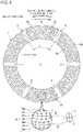
Fig. 6 is taken along line W-W ofFig. 1 , which shows an example of a sliding surface of a sliding component according toEmbodiment 5 of the present invention; -
Fig. 7 is taken along line W-W ofFig. 1 , which shows an example of a sliding surface of a sliding component according toEmbodiment 6 of the present invention; andFigs. 8A to 8D are examples of a closed curve having a short axis and a long axis. - Hereinafter, modes for carrying out the present invention will be exemplified based on embodiments with reference to the drawings. However, unless otherwise specified, dimensions, materials, shapes, relative positions, and the like of components described in the embodiments are not intended to limit the scope of the present invention.
- A sliding component according to Embodiment 1 of the present invention will be described with reference to
Figs. 1 and2 . In the following embodiment, a mechanical seal, which is an example of a sliding component, will be described as an example. However, the present invention is not limited thereto, and for example, the present invention may be used as a sliding component of a bearing that slides on a rotation shaft while sealing lubricating oil on one side in an axial direction of a cylindrical sliding surface. An outer peripheral side of the sliding component constituting the mechanical seal will be described as a sealed fluid side (a high-pressure fluid side), and an inner peripheral side will be described as a leakage side (a low-pressure fluid side, for example, an atmosphere side). -
Fig. 1 is a vertical cross-sectional view showing an example of a mechanical seal 1, which belongs to an inside type in which sealed fluid leaking from an outer periphery of a sliding surface S toward an inner peripheral direction is sealed, and includes a rotation-side cartridge and a fixed-side cartridge. The rotation-side cartridge includes asleeve 2 fitted to arotation shaft 10, an annular rotation-side sealing ring 3 that is one sliding component, and apacking 8 that seals space between thesleeve 2 and the rotation-side sealing ring 3. The rotation-side cartridge rotates together with therotation shaft 10. - The fixed-side cartridge includes a
housing 4 attached to acasing 9, an annular fixed-side sealing ring 5 that is another sliding component, abellows 7 that seals space between the fixed-side sealing ring 5 and the housing, and a coiledwave spring 6 that urges the fixed-side sealing ring 5 toward the rotation-side sealing ring 3 via thebellows 7. The housing is fixed to thecasing 9 in a rotation direction and an axial direction. - In the mechanical seal 1 having the above configuration, the sliding surface S of the rotation-
side sealing ring 3 and the sliding surface S of the fixed-side sealing ring 5 slide relative to each other so as to prevent the sealed fluid from flowing out from the outer peripheral side to the inner peripheral side. AlthoughFig. 1 shows a case where a width of the sliding surface of the rotation-side sealing ring 3 is wider than a width of the sliding surface of the fixed-side sealing ring 5, the present invention is not limited thereto, and it is needless to say that the present invention may also be applied in an opposite case. - Materials of the rotation-
side sealing ring 3 and the fixed-side sealing ring 5 are selected from silicon carbide (SiC) that has good wear resistance, carbon that has good self-lubricating performance, and the like. For example, both of the rotation-side sealing ring 3 and the fixed-side sealing ring 5 may be made of SiC, or the rotation-side sealing ring 3 may be made of SiC while the fixed-side sealing ring 5 is made of carbon. - As shown in
Fig. 2 , the sliding surface S of the fixed-side sealing ring 5 is partitioned into a predetermined number (six in the example ofFig. 1 ) ofregions 11 by land portions R provided from the sealed fluid side to the leakage side.Dimple groups 14 are arranged in the respective regions. Eachdimple group 14 is formed by arranging a plurality ofdimples 12. In addition, an axis CL is a radial axis that divides eachregion 11 symmetrically in a left-right direction. - In the present invention, each
dimple 12 is a recess that includes an opening portion surrounded by the flat sliding surface S and a bottom portion that is recessed relative to the sliding surface S.An opening portion 12a of thedimple 12 has a shape having a long axis L and a short axis K orthogonal to each other. In addition, thedimples 12 are spaced apart from each other with the land portions R interposed therebetween. In the present invention, the long axis L is an imaginary straight line that passes through a centroid G of the shape of theopening portion 12a and connects maximum width portions of theopening portion 12a. In addition, the short axis K is an imaginary straight line that passes through the centroid G and is orthogonal to the long axis L to connect the opening portion. In the present embodiment, as an example, the opening portion of the dimple 122 is an ellipse having the long axis L and the short axis K orthogonal to each other. However, the shape is not limited to the ellipse, and may also be an oval shape, a rhombus shape, a polygonal shape, or any shape formed byclosed curves Figs. 8A to 8D , as long as the shape has the long axis and the short axis orthogonal to each other. - As shown in
Fig. 2 , thedimple group 14 is formed by arranging a predetermined number ofsub dimple groups sub dimple groups dimples 12 are aligned along corresponding one ofimaginary curves 13 having a curvature different from a curvature of a circumference of the sliding surface S. That is, each sub dimple group has a shape in which the long axes L of thedimples 12 are aligned so as to be in contact with theimaginary curve 13. Thecurve 13 is a curve that is convex toward the sealed fluid side, and is formed of an arc, a parabola, a sine wave, a cycloid curve, or the like that has the curvature different from the curvature of the circumference of the sliding surface S. In addition, in thesub dimple groups dimples 12 arranged in the vicinity of the axis CL are arranged to be closest to the sealed fluid side, and thedimples 12 arranged at both ends of theregion 11 are arranged to be closest to the leakage side. In addition, thedimples 12 arranged at the both ends of each of thesub dimple groups peripheral edge 5a or to be opened toward the leakage-sideperipheral edge 5a. Further, thesub dimple groups dimples 12 are arranged symmetrically relative to the axis CL. Hereinafter, in the present invention, the circumference of the sliding surface S indicates a locus of points at an equal distance from a center C of the sliding surface S. - Although the long axes L of the
dimples 12 are arranged close to each other and aligned such that the long axes L of thedimples 12 constituting the sub dimple group are in contact with theimaginary curve 13 in Embodiment 1, the long axes L of thedimples 12 may also be arranged to be inclined at a predetermined angle relative to theimaginary curve 13. In addition, for the sake of explanation, reference numerals of thesub dimple groups Fig. 2 . The number of sub dimple groups arranged in eachregion 11 is determined based on design conditions and the like. - When the rotation-
side sealing ring 3 of the mechanical seal 1 configured as described above rotates in a counterclockwise direction as shown inFig. 2 , fluid between the sliding surfaces S and fluid in eachdimple 12 are moved following a moving direction of the rotation-side sealing ring 3 due to viscosity of the fluid. Since a flow path of the fluid flowing into thedimple 12 rapidly expands, negative pressure is generated on an upstream side of thedimple 12, and thus cavitation occurs. However, since a magnitude of the negative pressure in the cavitation is limited by a value of fluid vapor pressure, the negative pressure does not become large. In addition, on a downstream side of thedimple 12, positive pressure (dynamic pressure effect) is generated by a wedge effect due to rapid contraction of a flow path. Due to the negative pressure generated on the upstream side of thedimple 12, thedimple 12 exhibits a suction effect of suctioning surrounding fluid. On the other hand, since the positive pressure generated on the downstream side of thedimple 12 is larger than the negative pressure in the cavitation, theentire dimple 12 becomes positive pressure. Due to the positive pressure generated by the plurality ofdimples 12 arranged in the sliding surface S, space between the sliding surfaces S is expanded, and thus the fluid flows onto the sliding surface S to exert a lubricating function. - When the
dimples 12 are arranged from the leakage-sideperipheral edge 5a to a sealed-fluid-sideperipheral edge 5b of the sliding surface S, thedimple group 14 exhibits a pumping effect of suctioning the fluid onto the sliding surface from the leakage side, and thus a sealing effect is improved. In addition, since high-pressure fluid is suctioned from the sealed fluid side to supply the fluid pressurized by the dynamic pressure effect of thedimples 12 to the sliding surface, a fluid lubricating effect can be improved. In particular, when thedimples 12 are arranged to form the shape of thecurve 13 that is convex toward the sealed fluid side as in thesub dimple groups Fig. 2 , the sealing effect of thedimple group 14 is improved as compared with a dimple group in which dimples are arranged concentrically in a circumferential direction of the sliding surface S. - In addition, since each
dimple 12 includes theelliptical opening portion 12a that has the long axis and the short axis orthogonal to each other, the suction effect and the dynamic pressure effect of thedimple 12 become different depending on inclination of the long axis L. When the long axis L of thedimple 12 is arranged along a circumferential direction, a fluid holding function of thedimple 12 is improved. When the long axis L of thedimple 12 is inclined by about 45° relative to a radial axis r, the suction effect is improved. In addition, when the long axis L of thedimple 12 is arranged along a radial direction, the dynamic pressure effect is improved. In this way, even when thedimple 12 has the same elliptical shape, the suction effect and the dynamic pressure effect may be increased or decreased by changing the inclination of the long axis L of thedimple 12. - In addition, since the
dimples 12 are arranged along thecurve 13 in thesub dimple groups dimple 12 gradually changes along thecurve 13. As a result, since a direction of the long axis L of eachdimple 12 gradually changes along thecurve 13, thesub dimple groups dimples 12 having different suction effects and dynamic pressure effects. Even when the mechanical seal 1 is used in a wide rotation speed range, since thedimples 12 suitable for each rotation speed exhibit favorable suction effect and dynamic pressure effect, thedimple group 14 as a whole exhibits favorable sealing performance and lubricating function. - Further, the
sub dimple groups curve 13 so as to be convex toward the sealed fluid side, and therefore, thesub dimple groups - As described above, the sliding component of the present invention has the following effects.
- 1. The
dimples 12 constituting thedimple group 14 have negative pressure on the upstream side thereof so as to exhibit a fluid suctioning effect, and exhibit a lubricating function since fluid pressurized by a wedge effect on the downstream side is supplied to the sliding surface. - 2. When the
dimples 12 are arranged from the leakage-sideperipheral edge 5a to the sealed-fluid-sideperipheral edge 5b of the sliding surface S, thedimple group 14 exhibits a pumping effect of suctioning the fluid onto the sliding surface from the leakage side, and thus a sealing effect can be improved. In addition, since high-pressure fluid is suctioned from the sealed fluid side to supply the fluid pressurized by the dynamic pressure effect of thedimples 12 to the sliding surface, a fluid lubricating effect can be improved. - 3. When the
dimples 12 are arranged to form the shape of thecurve 13 that is convex toward the sealed fluid side as in thesub dimple groups Fig. 2 , the sealing effect of thedimple group 14 can be improved as compared with a dimple group in which dimples are arranged concentrically in a circumferential direction of the sliding surface S. - 4. Since each
dimple 12 includes theelliptical opening portion 12a that has the long axis and the short axis orthogonal to each other, strength of the suction effect and the dynamic pressure effect of thedimple 12 can be changed by changing the inclination of the long axis L. As a result, even when thedimple 12 has the same elliptical shape, the suction effect and the dynamic pressure effect can be improved by changing the inclination of the long axis L of thedimple 12. - 5. Since the
dimples 12 are arranged along thecurve 13 in thesub dimple groups dimple 12 gradually changes along thecurve 13. As a result, since the direction of the long axis L of eachdimple 12 gradually changes along thecurve 13, thesub dimple groups dimples 12 having different suction effects and dynamic pressure effects. Even when the mechanical seal 1 is used in a wide rotation speed range, since thedimples 12 suitable for each rotation speed exhibit favorable suction effect and dynamic pressure effect, thedimple group 14 as a whole exhibits favorable sealing performance and lubricating function. - 6. The
sub dimple group 14 is arranged substantially symmetrically relative to the axis CL so as to form thecurve 13 that is convex toward the sealed fluid side, and therefore, thesub dimple group 14 exhibits favorable suction effect and dynamic pressure effect not only during forward rotation but also during reverse rotation. - A sliding component according to
Embodiment 2 of the present invention will be described.Fig. 3 shows the sliding surface S of the sliding component according toEmbodiment 2 in whichsub dimple groups curve 23 that is convex toward the leakage side, which is different from Embodiment 1. Other configurations are the same as those of Embodiment 1. Hereinafter, the same members and configurations as those of Embodiment 1 will be denoted by the same reference numerals, and redundant description thereof will be omitted. - As shown in
Fig. 3 , the sliding surface S of the fixed-side sealing ring 5 is partitioned into a predetermined number (six in the example ofFig. 3 ) ofregions 21 by the land portions R provided from the sealed fluid side to the leakage side.Dimple groups 24 are arranged in the respective regions. Eachdimple group 24 is formed by arranging a plurality ofdimples 22. In addition, the axis CL is a radial axis that divides eachregion 21 symmetrically in the left-right direction. - As shown in
Fig. 3 , thedimple group 24 is formed by arranging a predetermined number ofsub dimple groups sub dimple groups dimples 22 are aligned to form theimaginary curve 23 having a curvature different from the curvature of the circumference of the sliding surface S. That is, each sub dimple group has a shape in which the long axes L of thedimples 22 are aligned so as to be in contact with theimaginary curve 23. Thecurve 23 is a curve that is convex toward the leakage side, and is formed of an arc, a parabola, a sine wave, a cycloid curve, or the like that has the curvature different from the curvature of the circumference of the sliding surface S. In addition, in thesub dimple groups dimples 22 arranged in the vicinity of the axis CL are arranged closest to the leakage side, and thedimples 22 arranged at both ends are arranged closest to the sealed fluid side. In addition, thedimples 22 arranged at both ends of each of thesub dimple groups peripheral edge 5b or to be opened toward the sealed-fluid-sideperipheral edge 5b. Further, thesub dimple groups dimples 22 are arranged symmetrically relative to the axis CL. For the sake of explanation, reference numerals of thesub dimple groups Fig. 3 . The number of sub dimple groups arranged in eachregion 21 is determined base on design conditions and the like. - When the
dimples 22 are arranged close to each other and along thecurve 23 as in thesub dimple groups adjacent dimples 22. Therefore, when thedimples 22 are arranged from the leakage-sideperipheral edge 5a to the sealed-fluid-sideperipheral edge 5b of the sliding surface S, thedimple group 24 exhibits a pumping effect of suctioning the fluid onto the sliding surface from the leakage side, and thus leakage can be reduced. In addition, since high-pressure fluid is suctioned from the sealed fluid side and fluid pressurized by a dynamic pressure effect of eachdimple 22 is supplied to the sliding surface, a fluid lubricating effect can be improved. In particular, as shown inFig. 3 , when thedimples 22 are arranged along thecurve 23 that is convex toward the leakage side as in thesub dimple groups dimple group 24 can be stronger than a sealing effect thereof. - In addition, since the
dimples 22 are arranged along thecurve 23 in thesub dimple groups dimple 22 gradually changes along thecurve 23, and thus a suction effect and the dynamic pressure effect of each dimple also gradually change along thecurve 23. That is, since thedimples 22 having different suction effects and dynamic pressure effects are arranged in thesub dimple groups dimples 22 exhibiting favorable suction effect and dynamic pressure effect at each rotation speed. By arranging thedimple group 24 in which the plurality ofsub dimple groups region 21 of the sliding surface, thedimple group 24 as a whole exhibits a lubricating function even when used in a wide rotation speed range. - Further, the
sub dimple groups curve 23 that is convex toward the sealed fluid side, and therefore, thesub dimple groups - As described above, the sliding component of
Embodiment 2 has the following effects. - 1. The
dimples 22 constituting thedimple group 24 have negative pressure on an upstream side thereof so as to exhibit a fluid suctioning function, and exhibit a lubricating function by discharging fluid pressurized by a wedge effect on a downstream side. - 2. When the
dimples 22 are arranged from the leakage-sideperipheral edge 5a to the sealed-fluid-sideperipheral edge 5b of the sliding surface S, thedimple group 24 exhibits a pumping effect of suctioning the fluid onto the sliding surface from the leakage side, and thus leakage can be reduced. In addition, since high-pressure fluid is suctioned from the sealed fluid side and fluid pressurized by the dynamic pressure effect of eachdimple 22 is supplied to the sliding surface, a fluid lubricating effect can be improved. - 3. When the
dimples 22 are arranged to form the shape of thecurve 23 that is convex toward the leakage side as in thesub dimple groups Fig. 3 , the fluid lubricating effect of thedimple group 24 can be improved as compared with a dimple group in which dimples are arranged concentrically in the circumferential direction of the sliding surface S. - 4. Since each
dimple 22 includes anelliptical opening portion 22a that has the long axis and the short axis orthogonal to each other, strength of the suction effect and the dynamic pressure effect of thedimple 22 can be changed by changing the inclination of the long axis L. As a result, even when thedimple 22 has the same elliptical shape, the suction effect and the dynamic pressure effect can be improved by changing the inclination of the long axis L of thedimple 22. - 5. Since the
dimples 22 are arranged along thecurve 23 in thesub dimple groups dimple 22 gradually changes along thecurve 23, and thus the suction effect and the dynamic pressure effect of each dimple also gradually change along thecurve 23. That is, since thedimples 22 having different suction effects and dynamic pressure effects are arranged in thesub dimple groups dimples 22 exhibiting favorable suction effect and dynamic pressure effect at each rotation speed. By arranging thedimple group 24 in which the plurality ofsub dimple groups region 21 of the sliding surface, thedimple group 24 as a whole exhibits a lubricating function even when used in a wide rotation speed range. - 6. The
sub dimple groups curve 23 that is convex toward the sealed fluid side, and therefore, thesub dimple groups - A sliding product according to
Embodiment 3 of the present invention will be described.Fig. 4 shows the sliding surface S of a sliding component according toEmbodiment 3 in which adimple group 34 is arranged such that the short axes K ofadjacent dimples 32 are arranged close to each other and aligned to form acurve 33 that is convex toward the sealed fluid side, which is different from Embodiment 1. Other configurations are the same as those of Embodiment 1. Hereinafter, the same members and configurations as those of Embodiment 1 will be denoted by the same reference numerals, and redundant description thereof will be omitted. - As shown in
Fig. 4 , the sliding surface S of the fixed-side sealing ring 5 is partitioned into a predetermined number (six in the example ofFig. 4 ) ofregions 31 by the land portions R provided from the sealed fluid side to the leakage side. Thedimple groups 34 are arranged in the respective regions. Eachdimple group 34 is formed by arranging a plurality of thedimples 32. In addition, the axis CL is a radial axis that divides eachregion 31 symmetrically in the left-right direction. - As shown in
Fig. 4 , thedimple group 34 is formed by arranging a predetermined number ofsub dimple groups sub dimple groups dimples 32 are aligned to form theimaginary curve 33 having a curvature different from the curvature of the circumference of the sliding surface S. That is, each sub dimple group has a shape in which the short axes K of thedimples 32 are aligned so as to be in contact with theimaginary curve 33. Thecurve 33 is a curve that is convex toward the sealed fluid side, and is formed of an arc, a parabola, a sine wave, a cycloid curve, or the like that has the curvature different from the curvature of the circumference of the sliding surface S. In addition, in thesub dimple groups dimples 32 arranged in the vicinity of the axis CL are arranged closest to the sealed fluid side, and thedimples 32 arranged at both ends are arranged closest to the leakage side. In addition, thedimples 12 arranged at both ends of each of thesub dimple groups peripheral edge 5a or to be opened toward the leakage-sideperipheral edge 5a. Further, thesub dimple groups dimples 32 are arranged symmetrically relative to the axis CL. Here, thecurve 33 is an imaginary curve that is in contact with the short axis K of eachdimple 32. For the sake of explanation, reference numerals of thesub dimple groups Fig. 4 . The number of sub dimple groups arranged in eachregion 31 is determined base on design conditions and the like. - In
Embodiment 3, a dynamic pressure effect of thedimple 32 can be better than a sealing effect thereof by arranging the long axes L of thedimples 32 in the radial direction. As a result, a lubricating effect of the sliding surface S as a whole can be improved, and thus sliding torque can be reduced. - In addition, when the
dimples 32 are arranged to form a shape of thecurve 33 that is convex toward the sealed fluid side as in thesub dimple groups Fig. 4 , a sealing effect of thedimple group 34 can be improved as compared with a dimple group in which dimples are arranged concentrically in the circumferential direction of the sliding surface S. - In addition, since the
dimples 32 are arranged along thecurve 33 in thesub dimple groups dimple 32 gradually changes along thecurve 33. As a result, a suction effect and the dynamic pressure effect of eachdimple 32 gradually change along thecurve 33. That is, since thedimples 32 exhibiting different suction effects and dynamic pressure effects are arranged in thesub dimple groups dimples 32 exhibiting favorable suction effect and dynamic pressure effect at each rotation speed. By arranging thedimple group 34 in which the plurality ofsub dimple groups region 31 of the sliding surface, thedimple group 34 as a whole exhibits favorable sealing performance and lubricating function even when used in a wide rotation speed range. - Further, the
sub dimple groups curve 33 that is convex toward the sealed fluid side, and therefore, thesub dimple groups - As described above, the sliding component of
Embodiment 3 has the following effects in addition to the effects of Embodiment 1. - 1. The dynamic pressure effect of the
dimple 32 can be better than the sealing effect thereof by arranging the long axes L of thedimples 32 in the radial direction. As a result, the lubricating effect of the sliding surface S as a whole can be improved, and thus sliding torque can be reduced. - 2. When the
dimples 32 are arranged to form the shape of thecurve 33 that is convex toward the sealed fluid side as in thesub dimple groups Fig. 4 , the sealing effect of thedimple group 34 can be improved as compared with a dimple group in which dimples are arranged concentrically in the circumferential direction of the sliding surface S. - A sliding product according to
Embodiment 4 of the present invention will be described.Fig. 5 shows the sliding surface S of a sliding component according toEmbodiment 4 in which adimple group 44 is arranged such that the short axes K ofadjacent dimples 42 are arranged close to each other and aligned to form acurve 43 that is convex toward the leakage side, which is different from Embodiment 1. Other configurations are the same as those of Embodiment 1. Hereinafter, the same members and configurations as those of Embodiment 1 will be denoted by the same reference numerals, and redundant description thereof will be omitted. - As shown in
Fig. 5 , the sliding surface S of the fixed-side sealing ring 5 is partitioned into a predetermined number (six in the example ofFig. 5 ) ofregions 41 by the land portions R provided from the sealed fluid side to the leakage side. Thedimple groups 44 are arranged in the respective regions. Eachdimple group 44 is formed by arranging a plurality of thedimples 42. In addition, the axis CL is a radial axis that divides eachregion 41 symmetrically in the left-right direction. - As shown in
Fig. 5 , thedimple group 44 is formed by arranging a predetermined number ofsub dimple groups sub dimple groups dimples 42 are aligned to form theimaginary curve 43 having a curvature different from the curvature of the circumference of the sliding surface S. That is, each sub dimple group has a shape in which the short axes K of thedimples 42 are aligned so as to be in contact with theimaginary curve 43. Thecurve 43 is a curve that is convex toward the leakage side, and is formed of an arc, a parabola, a sine wave, a cycloid curve, or the like that has the curvature different from the curvature of the circumference of the sliding surface S. In addition, in thesub dimple groups dimples 42 arranged in the vicinity of the axis CL are arranged closest to the leakage side, and thedimples 42 arranged at both ends are arranged closest to the sealed fluid side. In addition, thedimples 42 arranged at both ends of each of thesub dimple groups peripheral edge 5b or to be opened toward the sealed-fluid-sideperipheral edge 5b. Further, thesub dimple groups dimples 42 are arranged symmetrically relative to the axis CL. For the sake of explanation, reference numerals of thesub dimple groups Fig. 5 . The number of sub dimple groups arranged in eachregion 41 is determined base on design conditions and the like. - A dynamic pressure effect of the
dimple 42 can be better than a sealing effect thereof by arranging the long axes L of thedimples 42 in the radial direction. As a result, the lubricating effect of the sliding surface S as a whole can be improved, and thus sliding torque can be reduced. - When the
dimples 42 are arranged to form a shape of thecurve 43 that is convex toward the leakage side as in thesub dimple groups Fig. 5 , a fluid lubricating effect of thedimple group 44 can be improved as compared with a dimple group in which dimples are arranged concentrically in the circumferential direction of the sliding surface S. - In addition, since the
dimples 42 are arranged along thecurve 43 in thesub dimple groups dimple 42 gradually changes along thecurve 43. As a result, a suction effect and the dynamic pressure effect of eachdimple 42 gradually change along thecurve 43. That is, since thedimples 42 exhibiting different suction effects and dynamic pressure effects are arranged in thesub dimple groups dimples 42 exhibiting favorable suction effect and dynamic pressure effect at each rotation speed. By arranging thedimple group 44 in which the plurality ofsub dimple groups region 41 of the sliding surface, thedimple group 44 as a whole exhibits favorable sealing performance and lubricating function even when used in a wide rotation speed range. - Further, the
sub dimple groups curve 43 that is convex toward the leakage side, and therefore, thesub dimple groups - As described above, the sliding component of
Embodiment 4 has the following effects in addition to the effects ofEmbodiment 2. - 1. The dynamic pressure effect of the
dimple 42 can be better than the sealing effect thereof by arranging the long axes L of thedimples 42 in the radial direction. As a result, the lubricating effect of the sliding surface S as a whole can be improved, and thus sliding torque can be reduced. - 2. When the
dimples 42 are arranged to form the shape of thecurve 43 that is convex toward the leakage side as in thesub dimple groups Fig. 5 , the fluid lubricating effect of thedimple group 44 can be improved as compared with a dimple group in which dimples are arranged concentrically in the circumferential direction of the sliding surface S. - A sliding product according to
Embodiment 5 of the present invention will be described.Fig. 6 shows the sliding surface S of a sliding component according toEmbodiment 5 in which adimple group 54 arranged to form acurve 53 that is convex toward the sealed fluid side on the leakage side and adimple group 59 arranged to form acurve 58 that is convex toward the leakage side on the sealed fluid are provided, which is different from Embodiment 1. Other configurations are the same as those of Embodiment 1. Hereinafter, the same members and configurations as those of Embodiment 1 will be denoted by the same reference numerals, and redundant description thereof will be omitted. - As shown in
Fig. 6 , the sliding surface S of the fixed-side sealing ring 5 is partitioned into a predetermined number (six in the example ofFig. 6 ) ofregions 51 by the land portions R provided from the sealed fluid side to the leakage side. Thedimple groups dimple group 54 is formed by arranging a plurality ofdimples 52, and eachdimple group 59 is formed by arranging a plurality ofdimples 57. In addition, the axis CL is a radial axis that divides eachregion 51 symmetrically in the left-right direction. - The
dimple group 54 is arranged on the leakage side of the sliding surface S. Thedimple group 54 is formed by arranging a predetermined number ofsub dimple groups sub dimple groups dimples 52 are aligned to form theimaginary curve 53 having a curvature different from the curvature of the circumference of the sliding surface S. That is, each sub dimple group has a shape in which the long axes L of thedimples 52 are aligned so as to be in contact with theimaginary curve 53. Thecurve 53 is a curve that is convex toward the sealed fluid side, and is formed of an arc, a parabola, a sine wave, a cycloid curve, or the like that has the curvature different from the curvature of the circumference of the sliding surface S. In addition, in thesub dimple groups dimples 52 arranged in the vicinity of the axis CL are arranged closest to the sealed fluid side, and thedimples 52 arranged at both ends far from the axis CL are arranged closest to the leakage side. In addition, thedimples 52 arranged at both ends of each of thesub dimple groups peripheral edge 5a or to be opened toward the leakage-sideperipheral edge 5a. Further, thesub dimple groups dimples 52 are arranged symmetrically relative to the axis CL. For the sake of explanation, reference numerals of thesub dimple groups Fig. 6 . The number of sub dimple groups arranged in eachregion 51 is determined base on design conditions and the like. - The
dimple group 59 is arranged on the sealed fluid side of the sliding surface S. Thedimple group 59 is formed by arranging a predetermined number ofsub dimple groups sub dimple groups dimples 57 are aligned to form theimaginary curve 58 having a curvature different from the curvature of the circumference of the sliding surface S. That is, each sub dimple group has a shape in which the long axes L of thedimples 57 are aligned so as to be in contact with theimaginary curve 58. Thecurve 58 is a curve that is convex toward the leakage side, and is formed of an arc, a parabola, a sine wave, a cycloid curve, or the like that has the curvature different from the curvature of the circumference of the sliding surface S. In addition, in thesub dimple groups dimples 57 arranged in the vicinity of the axis CL are arranged closest to the leakage side, and thedimples 57 arranged at both ends are arranged closest to the sealed fluid side. In addition, thedimples 57 arranged at both ends of each of thesub dimple groups peripheral edge 5b or to be opened toward the sealed-fluid-sideperipheral edge 5b. Further, thesub dimple groups dimples 57 are arranged symmetrically relative to the axis CL. For the sake of explanation, reference numerals of thesub dimple groups Fig. 6 . - The
dimple group 54 that is provided on the leakage side of the sliding surface S and arranged to form thecurve 53 that is convex toward the sealed fluid side exhibits better sealing performance than dimples arranged concentrically in the circumferential direction of the sliding surface S. In addition, thedimple group 59 that is provided on the sealed fluid side of the sliding surface S and arranged to form thecurve 58 that is convex toward the leakage side of the sliding surface S exhibits a better lubricating effect than dimples arranged concentrically in the circumferential direction of the sliding surface S. By arranging thedimple group 54 having excellent sealing performance and thedimple group 59 having excellent lubricating performance on the sliding surface S in this manner, the mechanical seal 1 can exhibit excellent sealing performance and lubricating performance. - Since the
dimple group 54 is arranged substantially symmetrically relative to the axis CL so as to form thecurve 53 that is convex toward the sealed fluid side, thedimple group 54 can exhibit favorable sealing performance not only during forward rotation but also during reverse rotation. In addition, since thedimple group 59 is arranged substantially symmetrically relative to the axis CL so as to form thecurve 58 that is convex toward the leakage side, thedimple group 59 exhibits a lubricating function not only during forward rotation but also during reverse rotation, and thus can exhibit favorable sealing performance and lubricating performance regardless of a rotation direction thereof. - As described above, the sliding component of
Embodiment 5 has the following effects in addition to the effects ofEmbodiments 1 and 2. - 1. The
dimple group 54 that is provided on the leakage side of the sliding surface S and arranged to form thecurve 53 that is convex toward the sealed fluid side exhibits better sealing performance than dimples arranged concentrically in the circumferential direction of the sliding surface S. In addition, thedimple group 59 that is provided on the sealed fluid side of the sliding surface S and arranged to form thecurve 58 that is convex toward the leakage side of the sliding surface S exhibits a better lubricating effect than dimples arranged concentrically in the circumferential direction of the sliding surface S. - 2. Since the
dimple group 54 is arranged substantially symmetrically relative to the axis CL while thedimple group 59 is arranged substantially symmetrically relative to the axis CL, favorable sealing performance and lubricating performance can be exhibited regardless of rotation directions. - A sliding product according to
Embodiment 6 of the present invention will be described.Fig. 7 shows the sliding surface S of a sliding component according toEmbodiment 6 in which a groove portion is provided between adimple group 64 arranged to form acurve 63 that is convex toward the sealed fluid side on the leakage side and adimple group 69 arranged to form acurve 68 that is convex toward the leakage side on the sealed fluid, which is different fromEmbodiment 5. Other configurations are the same as those ofEmbodiment 5. Hereinafter, the same members and configurations as those ofEmbodiment 5 will be denoted by the same reference numerals, and redundant description thereof will be omitted. - As shown in
Fig. 7 , the sliding surface S of the fixed-side sealing ring 5 is partitioned into a predetermined number (six in the example ofFig. 7 ) ofregions 61 by the land portions R provided from the sealed fluid side to the leakage side. Thedimple groups dimple group 64 is formed by arranging a plurality ofdimples 62, and eachdimple group 69 is formed by arranging a plurality ofdimples 67. In addition, the axis CL is a radial axis that divides eachregion 61 symmetrically in the left-right direction. - As in
Embodiment 5, thedimple group 64 arranged to form thecurve 63 that is convex toward the sealed fluid side is arranged on the leakage side of the sliding surface S. Thedimple group 64 is formed by arranging a predetermined number ofsub dimple groups sub dimple groups dimples 62 are aligned to form theimaginary curve 63 having a curvature different from the curvature of the circumference of the sliding surface S. Thecurve 63 is a curve that is convex toward the sealed fluid side, and is formed of an arc, a parabola, a sine wave, a cycloid curve, or the like that has the curvature different from the curvature of the circumference of the sliding surface S. In addition, in thesub dimple groups dimples 62 arranged in the vicinity of the axis CL are arranged closest to the sealed fluid side, and thedimples 62 arranged at both ends are arranged closest to the leakage side. In addition, thedimples 62 arranged at both ends of each of thesub dimple groups peripheral edge 5a or to be opened toward the leakage-sideperipheral edge 5a. Further, thesub dimple groups dimples 62 are arranged symmetrically relative to the axis CL. For the sake of explanation, reference numerals of thesub dimple groups Fig. 7 . The number of sub dimple groups arranged in eachregion 61 is determined based on design conditions and the like. - As in
Embodiment 5, thedimple group 69 arranged to form thecurve 68 that is convex toward the leakage side is arranged on the sealed fluid side of the sliding surface S. Thedimple group 69 is formed by arranging a predetermined number ofsub dimple groups sub dimple groups dimples 67 are aligned to form theimaginary curve 68 having a curvature different from the curvature of the circumference of the sliding surface S. Thecurve 68 is a curve that is convex toward the leakage side, and is formed of an arc, a parabola, a sine wave, a cycloid curve, or the like that has the curvature different from the curvature of the circumference of the sliding surface S. In addition, in thesub dimple groups dimples 57 arranged in the vicinity of the axis CL are arranged closest to the leakage side, and thedimples 67 arranged at both ends are arranged closest to the sealed fluid side. In addition, thedimples 67 arranged at both ends of each of thesub dimple groups peripheral edge 5b or to be opened toward the sealed-fluid-sideperipheral edge 5b. Further, thesub dimple groups dimples 67 are arranged symmetrically relative to the axis CL. For the sake of explanation, reference numerals of thesub dimple groups Fig. 7 . - A
groove portion 65 is provided between thedimple group 64 and thedimple group 69. Thegroove portion 65 is formed to be sufficiently deeper than depths of thedimples 62 constituting thedimple group 64 and thedimples 67 constituting thedimple group 69, and to be sufficiently larger than sizes of opening portions of thedimples 62 and thedimples 67. - The
dimple group 64 that is provided on the leakage side of the sliding surface S and arranged to form thecurve 63 that is convex toward the sealed fluid side suctions fluid from the leakage side, and thus exhibits favorable sealing performance. In addition, thedimple group 69 that is provided on the sealed fluid side of the sliding surface S and arranged so as to form thecurve 68 that is convex toward the leakage side of the sliding surface S suctions fluid from the sealed fluid side and discharges pressurized fluid from the inside of thedimples 67 to the sliding surface S, and thus the sliding surface S can be maintained in a fluid lubricating state. By arranging thedimple group 64 having excellent sealing performance and thedimple group 69 having excellent lubricating performance on the sliding surface S in this manner, the mechanical seal 1 can exhibit excellent sealing performance and lubricating performance. - In addition, since the
groove portion 65 is provided between thedimple group 64 and thedimple group 69, interference between thedimple group 64 and thedimple group 69 can be prevented. As a result, it is possible to prevent functions of thedimple group 64 that exhibits sealing performance and thedimple group 69 that exhibits lubricating performance from cancelling out each other in a region where thedimple group 64 and thedimple group 69 are close to each other. - The
dimple group 64 is arranged substantially symmetrically relative to the axis CL so as to form thecurve 63 that is convex toward the sealed fluid side, and therefore, thedimple group 64 exhibits favorable sealing performance not only during forward rotation but also during reverse rotation. Since thedimple group 69 is arranged substantially symmetrically relative to the axis CL so as to form thecurve 68 that is convex toward the leakage side, thedimple group 69 exhibits a lubricating function not only during forward rotation but also during reverse rotation, and thus can exhibit favorable sealing performance and lubricating performance regardless of a rotation direction thereof. - As described above, the sliding component of
Embodiment 6 has the following effects in addition to the effects ofEmbodiment 5. - In the mechanical seal of
Embodiment 6, since thegroove portion 65 is provided between thedimple group 64 and thedimple group 69, interference between thedimple group 64 and thedimple group 69 can be prevented. As a result, it is possible to prevent the functions of thedimple group 64 that exhibits sealing performance and thedimple group 69 that exhibits lubricating performance from cancelling out each other in the region where thedimple group 64 and thedimple group 69 are close to each other. - Although the embodiments of the present invention have been described above with reference to the drawings, the specific configuration is not limited to these embodiments, and changes and additions without departing from the spirit of the present invention are also included in the present invention.
- Although the outer peripheral side is the sealed fluid side while the inner peripheral side is the leakage side in the above embodiment, the present invention is not limited thereto, and the present invention is also applicable to a case where the inner peripheral side is the sealed fluid side while the outer peripheral side is the leakage side.
-
- 1 mechanical seal
- 2 sleeve
- 3 rotation-side sealing ring
- 4 housing
- 5 fixed-side sealing ring
- 6 coiled wave spring
- 7 bellows
- 8 packing
- 9 casing
- 10 rotation shaft
- 11 region
- 12 dimple
- 14 dimple group
- 14a sub dimple group
- 14b sub dimple group
- 14c sub dimple group
- 14d sub dimple group
- 14e sub dimple group
- 14f sub dimple group
- 14g sub dimple group
- 21 region
- 22 dimple
- 24 dimple group
- 24a sub dimple group
- 24b sub dimple group
- 24c sub dimple group
- 24d sub dimple group
- 24e sub dimple group
- 24f sub dimple group
- 31 region
- 32 dimple
- 34 dimple group
- 34a sub dimple group
- 34b sub dimple group
- 34c sub dimple group
- 34d sub dimple group
- 34e sub dimple group
- 34f sub dimple group
- 34g sub dimple group
- 41 region
- 42 dimple
- 44 dimple group
- 44a sub dimple group
- 44b sub dimple group
- 44c sub dimple group
- 44d sub dimple group
- 44e sub dimple group
- 44f sub dimple group
- 44g sub dimple group
- 51 region
- 52 dimple
- 54 dimple group
- 54a sub dimple group
- 54b sub dimple group
- 54c sub dimple group
- 54d sub dimple group
- 57 dimple
- 59 dimple group
- 59a sub dimple group
- 59b sub dimple group
- 59c sub dimple group
- 61 region
- 62 dimple
- 64 dimple group
- 64a sub dimple group
- 64b sub dimple group
- 64c sub dimple group
- 64d sub dimple group
- 65 groove portion
- 67 dimple
- 69 dimple group
- 69a sub dimple group
- 69b sub dimple group
- 69c sub dimple group
- K short axis
- L long axis
- R land portion
- S sliding surface
- θ dimple angle
Claims (11)
- A sliding component comprising a pair of sliding members being slidable relative to each other on sliding surfaces of the sliding members,wherein at least one of the sliding surfaces includes a dimple group in which a plurality of dimples is arranged, each of the dimple having an opening portion a shape of which has a long axis and a short axis orthogonal to the long axis, andin the dimple group, the dimples are arranged along a curve having a curvature different from a curvature of a circumference of the sliding surface.
- The sliding component according to claim 1, wherein the dimple group includes a first dimple group in which the dimples are arranged along a curve that is convex toward a sealed fluid side of the sliding component.
- The sliding component according to claim 2, wherein the first dimple group is arranged on a leakage side of the sliding surface.
- The sliding component according to claim 1, wherein the dimple group includes a second dimple group in which the dimples are arranged along a curve that is convex toward a leakage side of the sliding component.
- The sliding component according to claim 4, wherein the second dimple group is arranged on a sealed fluid side of the sliding surface.
- The sliding component according to claim 1, wherein the dimple group includes:a first dimple group in which the dimples are arranged along a curve that is convex toward a sealed fluid side of the sliding component; anda second dimple group in which the dimples are arranged along a curve that is convex toward a leakage side of the sliding component.
- The sliding component according to claim 6, wherein the first dimple group is arranged on the leakage side of the sliding surface, and the second dimple group is arranged on the sealed fluid side of the sliding surface.
- The sliding component according to claim 6 or 7, further comprising:
a circumferential groove extending in a circumferential direction and being disposed between the first dimple group and the second dimple group. - The sliding component according to any one of claims 1 to 8, wherein the s sliding surface includes a plurality of regions partitioned by land portions each extending in a corresponding radial direction, and
the dimple group is disposed in one of the regions. - The sliding component according to any one of claims 1 to 9, wherein the opening portion of the dimple is elliptical.
- The sliding component according to any one of claims 1 to 10, wherein in the dimple group, the long axes or the short axes of the dimples are aligned to form the curve.
Applications Claiming Priority (1)
| Application Number | Priority Date | Filing Date | Title |
|---|---|---|---|
| PCT/JP2020/015742 WO2021205554A1 (en) | 2020-04-07 | 2020-04-07 | Sliding component |
Publications (2)
| Publication Number | Publication Date |
|---|---|
| EP4102111A1 true EP4102111A1 (en) | 2022-12-14 |
| EP4102111A4 EP4102111A4 (en) | 2023-10-18 |
Family
ID=78023111
Family Applications (1)
| Application Number | Title | Priority Date | Filing Date |
|---|---|---|---|
| EP20929917.1A Pending EP4102111A4 (en) | 2020-04-07 | 2020-04-07 | SLIDING COMPONENT |
Country Status (6)
| Country | Link |
|---|---|
| US (2) | US11994216B2 (en) |
| EP (1) | EP4102111A4 (en) |
| JP (1) | JP7385006B2 (en) |
| KR (1) | KR102744486B1 (en) |
| CN (2) | CN120701751A (en) |
| WO (1) | WO2021205554A1 (en) |
Family Cites Families (19)
| Publication number | Priority date | Publication date | Assignee | Title |
|---|---|---|---|---|
| JPS5760513Y2 (en) | 1977-09-29 | 1982-12-23 | ||
| DE3143508A1 (en) * | 1980-11-04 | 1982-08-26 | Eagle Industry Co. Ltd., Tokyo | SHAFT SEAL AND METHOD FOR THE PRODUCTION OF A SLIDE SURFACE THEREOF |
| US6902168B2 (en) * | 2002-03-19 | 2005-06-07 | Eagle Industry Co., Ltd. | Sliding element |
| JP4719414B2 (en) | 2003-12-22 | 2011-07-06 | イーグル工業株式会社 | Sliding parts |
| JP2010133496A (en) | 2008-12-04 | 2010-06-17 | Eagle Ind Co Ltd | Sliding part |
| EP2375112B1 (en) | 2009-05-25 | 2018-07-18 | Eagle Industry Co., Ltd. | Sealing device |
| JP5518527B2 (en) * | 2010-03-04 | 2014-06-11 | イーグル工業株式会社 | Sliding parts |
| CN102022542B (en) * | 2010-12-11 | 2013-04-03 | 浙江工业大学 | A negative pressure groove end face mechanical seal structure |
| CN104154235B (en) * | 2014-05-07 | 2017-01-25 | 清华大学 | Spiral distribution convergent micropore texture mechanical seal |
| KR101970231B1 (en) * | 2015-02-14 | 2019-04-18 | 이구루코교 가부시기가이샤 | Sliding parts |
| CN106015572B (en) * | 2016-07-27 | 2018-05-08 | 浙江工业大学 | Bi-directionally rotatable cross-scale slotted hole combined end face mechanical sealing structure |
| US11143232B2 (en) * | 2016-11-16 | 2021-10-12 | Eagle Industry Co., Ltd. | Sliding component |
| KR102276083B1 (en) * | 2017-01-30 | 2021-07-13 | 이구루코교 가부시기가이샤 | sliding parts |
| CN106838323B (en) * | 2017-03-30 | 2018-05-04 | 浙江工业大学 | A kind of end surface mechanical sealing structure of imitative shark skin surface three-dimensional appearance |
| WO2018212144A1 (en) * | 2017-05-19 | 2018-11-22 | イーグル工業株式会社 | Sliding component |
| US11168793B2 (en) * | 2017-05-19 | 2021-11-09 | Eagle Industry Co., Ltd. | Sliding component |
| US11035411B2 (en) * | 2017-07-14 | 2021-06-15 | Eagle Industry Co., Ltd. | Sliding parts |
| EP3693638A4 (en) * | 2017-10-03 | 2021-06-23 | Eagle Industry Co., Ltd. | Sliding component |
| CN110242751B (en) * | 2019-06-28 | 2024-07-16 | 清华大学 | Multi-layer double-row groove seal end face structure for rotating machinery |
-
2020
- 2020-04-07 KR KR1020227030698A patent/KR102744486B1/en active Active
- 2020-04-07 JP JP2022513756A patent/JP7385006B2/en active Active
- 2020-04-07 CN CN202511127990.XA patent/CN120701751A/en active Pending
- 2020-04-07 CN CN202080098179.2A patent/CN115244319B/en active Active
- 2020-04-07 EP EP20929917.1A patent/EP4102111A4/en active Pending
- 2020-04-07 US US17/908,699 patent/US11994216B2/en active Active
- 2020-04-07 WO PCT/JP2020/015742 patent/WO2021205554A1/en not_active Ceased
-
2024
- 2024-03-07 US US18/598,371 patent/US12510162B2/en active Active
Also Published As
| Publication number | Publication date |
|---|---|
| US11994216B2 (en) | 2024-05-28 |
| US20240247722A1 (en) | 2024-07-25 |
| WO2021205554A1 (en) | 2021-10-14 |
| US20230160475A1 (en) | 2023-05-25 |
| KR102744486B1 (en) | 2024-12-18 |
| JP7385006B2 (en) | 2023-11-21 |
| EP4102111A4 (en) | 2023-10-18 |
| CN115244319A (en) | 2022-10-25 |
| JPWO2021205554A1 (en) | 2021-10-14 |
| CN115244319B (en) | 2025-11-18 |
| CN120701751A (en) | 2025-09-26 |
| US12510162B2 (en) | 2025-12-30 |
| KR20220137729A (en) | 2022-10-12 |
Similar Documents
| Publication | Publication Date | Title |
|---|---|---|
| US11608897B2 (en) | Slide component | |
| JP6058018B2 (en) | Sliding parts | |
| KR102459648B1 (en) | sliding parts | |
| JP6456950B2 (en) | Sliding parts | |
| US11053975B2 (en) | Sliding component | |
| CN113454353A (en) | Sliding component | |
| JP7171553B2 (en) | sliding parts | |
| WO2023053964A1 (en) | Sliding component | |
| US12510162B2 (en) | Sliding component | |
| US11994217B2 (en) | Sliding component | |
| US12038087B2 (en) | Sliding component | |
| EP4130523B1 (en) | Sliding component | |
| WO2025239228A1 (en) | Sliding component | |
| JPWO2021205554A5 (en) | ||
| CN117859019A (en) | Sliding parts |
Legal Events
| Date | Code | Title | Description |
|---|---|---|---|
| STAA | Information on the status of an ep patent application or granted ep patent |
Free format text: STATUS: THE INTERNATIONAL PUBLICATION HAS BEEN MADE |
|
| PUAI | Public reference made under article 153(3) epc to a published international application that has entered the european phase |
Free format text: ORIGINAL CODE: 0009012 |
|
| STAA | Information on the status of an ep patent application or granted ep patent |
Free format text: STATUS: REQUEST FOR EXAMINATION WAS MADE |
|
| 17P | Request for examination filed |
Effective date: 20220906 |
|
| AK | Designated contracting states |
Kind code of ref document: A1 Designated state(s): AL AT BE BG CH CY CZ DE DK EE ES FI FR GB GR HR HU IE IS IT LI LT LU LV MC MK MT NL NO PL PT RO RS SE SI SK SM TR |
|
| DAV | Request for validation of the european patent (deleted) | ||
| DAX | Request for extension of the european patent (deleted) | ||
| A4 | Supplementary search report drawn up and despatched |
Effective date: 20230914 |
|
| RIC1 | Information provided on ipc code assigned before grant |
Ipc: F16J 15/34 20060101AFI20230908BHEP |
|
| STAA | Information on the status of an ep patent application or granted ep patent |
Free format text: STATUS: EXAMINATION IS IN PROGRESS |
|
| 17Q | First examination report despatched |
Effective date: 20250326 |