EP4102077A1 - Pump casing - Google Patents
Pump casing Download PDFInfo
- Publication number
- EP4102077A1 EP4102077A1 EP22177047.2A EP22177047A EP4102077A1 EP 4102077 A1 EP4102077 A1 EP 4102077A1 EP 22177047 A EP22177047 A EP 22177047A EP 4102077 A1 EP4102077 A1 EP 4102077A1
- Authority
- EP
- European Patent Office
- Prior art keywords
- pump
- pump casing
- passage portion
- suction
- discharge
- Prior art date
- Legal status (The legal status is an assumption and is not a legal conclusion. Google has not performed a legal analysis and makes no representation as to the accuracy of the status listed.)
- Pending
Links
Images


Classifications
-
- F—MECHANICAL ENGINEERING; LIGHTING; HEATING; WEAPONS; BLASTING
- F04—POSITIVE - DISPLACEMENT MACHINES FOR LIQUIDS; PUMPS FOR LIQUIDS OR ELASTIC FLUIDS
- F04D—NON-POSITIVE-DISPLACEMENT PUMPS
- F04D13/00—Pumping installations or systems
- F04D13/12—Combinations of two or more pumps
- F04D13/14—Combinations of two or more pumps the pumps being all of centrifugal type
-
- F—MECHANICAL ENGINEERING; LIGHTING; HEATING; WEAPONS; BLASTING
- F04—POSITIVE - DISPLACEMENT MACHINES FOR LIQUIDS; PUMPS FOR LIQUIDS OR ELASTIC FLUIDS
- F04D—NON-POSITIVE-DISPLACEMENT PUMPS
- F04D15/00—Control, e.g. regulation, of pumps, pumping installations or systems
- F04D15/0072—Installation or systems with two or more pumps, wherein the flow path through the stages can be changed, e.g. series-parallel
-
- F—MECHANICAL ENGINEERING; LIGHTING; HEATING; WEAPONS; BLASTING
- F04—POSITIVE - DISPLACEMENT MACHINES FOR LIQUIDS; PUMPS FOR LIQUIDS OR ELASTIC FLUIDS
- F04D—NON-POSITIVE-DISPLACEMENT PUMPS
- F04D29/00—Details, component parts, or accessories
- F04D29/60—Mounting; Assembling; Disassembling
- F04D29/605—Mounting; Assembling; Disassembling specially adapted for liquid pumps
Definitions
- the present invention relates to a pump casing.
- a pump apparatus is conventionally used for various applications in various kinds of houses and in a site such as a factory.
- an inline pump in which a pump section and a motor section are integrated, and a suction port and a discharge port of a pump are arranged on the same line is widely used because the inline pump is easily attachable in a middle of a pipe.
- the inline pump is installed in a construction facility, it is desirable to avoid stoppage of liquid supply when one inline pump has failed or one inline pump is subjected to periodic inspection.
- twin pump in which two inline pumps are arranged in parallel, one suction port and one discharge port are connected to the two inline pumps, and the two inline pumps share one suction port and one discharge port. Note that, in the following, in a case where the two inline pumps do not share one suction port and one discharge port, namely, in a case where each of the two inline pumps includes one suction port and one discharge port, each of the pumps is called a single pump.
- twin pump In the case where the twin pump is installed, if trouble occurs on one of the pumps, or the like, parts other than a casing of the pump having the trouble are detached, and an upper part of the casing is covered with a blank flange.
- the parts other than the casing include an electric motor disposed on the upper part of the casing, a rotary shaft coupled to the electric motor, and an impeller fixed to the rotary shaft and housed in the casing.
- operation can be continued by the other pump during a pump maintenance period or during a period when a spare part for the failed pump is prepared.
- a product desirably saves space and has a long lifetime, and a pump manufacturer performs internal development in order to meet the demands.
- a length of a header pipe to branch a pipe into pipes for two single pumps or to merge pipes can be reduced as compared with a case where the two single pumps are arranged in parallel.
- a valve such as a check valve for backflow prevention is shared by the two pumps configuring the twin pump, which makes it possible to achieve space saving.
- the twin pump manufacturer can meet space saving required by a customer. Further, alternately operating the two pumps configuring the twin pump makes it possible to simply double the pump lifetime.
- a horizontal surface of a portion where the pump comes into contact with a floor for example, a pump bottom surface portion and a leg bottom surface portion is processed for each pump. Further, in a case where a single pump is installed, adjustment of a gap between a floor surface and the pump, and adjustment of a levelness of the pump are performed for each pump.
- An aspect of the present invention is made to solve such issues, and an object thereof is to provide a pump casing improved in stability of installed pumps.
- a pump casing used for a pump apparatus to transfer a liquid includes: a first pump casing; a first suction passage portion connected to the first pump casing; a first discharge passage portion connected to the first pump casing; a second pump casing; a second suction passage portion connected to the second pump casing; a second discharge passage portion connected to the second pump casing; a suction branching portion connected to the first suction passage portion and the second suction passage portion; a discharge merging portion connected to the first discharge passage portion and the second discharge passage portion; a first leg portion provided in the suction branching portion; and a second leg portion provided in the discharge merging portion.
- the first leg portion is provided in the suction branching portion, and the second leg portion is provided in the discharge merging portion. Since the leg portions are provided in the suction branching portion and the discharge merging portion, stability of the pump casing is increased. Occurrence of noise and vibration during operation of pumps can be suppressed as compared with an existing pump casing. Therefore, it is possible to provide the pump casing improved in stability of the installed pumps.
- At least one of the first leg portion and the second leg portion includes a screw hole.
- At least one of the first leg portion and the second leg portion includes a base part.
- the pump casing according to any one of the first to third aspects further includes a third leg portion provided in at least one of the first pump casing and the second pump casing.
- the pump casing according to any one of the first to fourth aspects further includes a fourth leg portion provided in at least one of the first discharge passage portion and the second discharge passage portion.
- the pump casing according to any one of the first to fifth aspects further includes a fifth leg portion provided in at least one of the first suction passage portion and the second suction passage portion.
- a pump apparatus includes: a first electric motor; a first rotary shaft coupled to the first electric motor; a first impeller fixed to the first rotary shaft and housed in the first pump casing; a second electric motor; a second rotary shaft coupled to the second electric motor; a second impeller fixed to the second rotary shaft and housed in the second pump casing; and the pump casing according to any one of the first to sixth aspects.
- Fig. 1 is a schematic view illustrating an embodiment of a pump casing 18 according to the present invention.
- the pump casing 18 is used for a pump apparatus 16 to transfer a liquid.
- One pump casing 18 includes a first pump casing 181, a first suction passage portion 201 connected to the first pump casing 181, and a first discharge passage portion 221 connected to the first pump casing 181.
- the pump casing 18 further includes a second pump casing 182, a second suction passage portion 202 connected to the second pump casing 182, and a second discharge passage portion 222 connected to the second pump casing 182.
- the pump casing 18 further includes a suction branching portion 24 connected to the first suction passage portion 201 and the second suction passage portion 202, and a discharge merging portion 26 connected to the first discharge passage portion 221 and the second discharge passage portion 222.
- the first pump casing 181, the first suction passage portion 201, the first discharge passage portion 221, the second pump casing 182, the second suction passage portion 202, the second discharge passage portion 222, the suction branching portion 24, and the discharge merging portion 26 are integrally formed as a casting. Some of these portions, for example, the first discharge passage portion 221, the second discharge passage portion 222, and the discharge merging portion 26 may be manufactured as castings other than the other portions.
- the suction branching portion 24 corresponds to a section from a suction port 20 to a part branched to the first suction passage portion 201 and the second suction passage portion 202. More specifically, the suction branching portion 24 corresponds to a section from the suction port 20 to a start end part 58 of the first suction passage portion 201, and a section from the suction port 20 to a start end part 60 of the second suction passage portion 202.
- the discharge merging portion 26 corresponds to a section from a part where the first discharge passage portion 221 and the second discharge passage portion 222 merge with each other to a discharge port 22.
- the discharge merging portion 26 corresponds to a section from a terminal end part 281 of the first discharge passage portion 221 to the discharge port 22, and a section from a terminal end part 282 of the second discharge passage portion 222 to the discharge port 22.
- the suction port 20 of the pump apparatus 16 is a connection portion between the pump apparatus 16 and a pipe (not illustrated) on a suction side of the pump apparatus 16.
- the discharge port 22 of the pump apparatus 16 is a connection portion between the pump apparatus 16 and a pipe (not illustrated) on a discharge side of the pump apparatus 16.
- the pump apparatus 16 includes a first pump apparatus 161 and a second pump apparatus 162.
- the first pump apparatus 161 and the second pump apparatus 162 may have the same configuration or different configurations.
- the first pump apparatus 161 and the second pump apparatus 162 substantially have the same configuration.
- a first impeller 51, the first pump casing 181, and the first discharge passage portion 221 respectively have the same dimensional shapes as a second impeller 52, the second pump casing 182, and the second discharge passage portion 222.
- a rotation direction 54 of the first impeller 51 is the same as a rotation direction 56 of the second impeller 52.
- the dimensional shape of the first suction passage portion 201 and the dimensional shape of the second suction passage portion 202 are slightly different from each other.
- the first pump apparatus 161 and the second pump apparatus 162 are centrifugal pumps; however, the first pump apparatus 161 and the second pump apparatus 162 are not limited to the centrifugal pumps as long as the first pump apparatus 161 and the second pump apparatus 162 are non-positive displacement pumps.
- the first pump apparatus 161 and the second pump apparatus 162 may be turbine pumps, axial-flow pumps, or mixed flow pumps.
- Fig. 2 is a schematic view illustrating an embodiment of the first pump apparatus 161.
- the first pump apparatus 161 includes a first electric motor 101, a first rotary shaft 121 coupled to the first electric motor 101, and the first impeller 51 that is fixed to the first rotary shaft 121 and is housed in the first pump casing 181.
- the second pump apparatus 162 also have a second electric motor, a second rotary shaft coupled to the second electric motor, and the second impeller 52 that is fixed to the second rotary shaft and is housed in the second pump casing 182, as with the first pump apparatus 161.
- the first impeller 51 is a centrifugal impeller.
- the rotary shaft 121 is rotatably supported by a bearing (not illustrated).
- the rotary shaft 121 and the first impeller 51 are integrally rotatable.
- the rotary shaft 121 and the first impeller 51 are rotated by the electric motor 101.
- a liner ring 102 is disposed around a fluid inlet 51a of the first impeller 51.
- the liner ring 102 is fixed to the first pump casing 181.
- a casing cover 122 is disposed between the electric motor 101 and the first pump casing 181. An opening at an upper part of the first pump casing 181 is closed by the casing cover 122.
- the electric motor 101 is fixed to the casing cover 122.
- the first pump casing 181 and the casing cover 122 are formed as castings.
- a shaft sealing device 15 sealing a gap between the rotary shaft 121 and the casing cover 122 is disposed on a rear side of the first impeller 51.
- the shaft sealing device 15 is held by the casing cover 122. Examples of the shaft sealing device 15 include a mechanical seal.
- the above-described blank flange (not illustrated) is disposed at a position of the casing cover 122 at maintenance or the like.
- the blank flange is attached by using screw holes 62 (see Fig. 3 ) circumferentially arranged for attachment of the casing cover 122.
- the blank flange has a disk shape, and includes, on an outer edge of the blank flange, attachment holes circumferentially arranged at positions corresponding to the screw holes 62.
- the pump casing 18 includes the suction branching portion 24 including the suction port 20, and the discharge merging portion 26 including the discharge port 22.
- the first impeller 51 is disposed inside the first pump casing 181.
- the suction port 20 and the discharge port 22 are arranged on one straight line.
- the pump apparatus 16 in which the suction port 20 and the discharge port 22 are arranged on one straight line is called an inline pump apparatus.
- two inline pumps are arranged in parallel, one suction port and one discharge port are connected to the two inline pumps, and the two inline pumps share one suction port and one discharge port. When the two inline pumps share one suction port and one discharge port, these pumps configure one twin pump as a whole.
- the pump casing 18 includes a first leg portion 38 provided in the suction branching portion 24, and a second leg portion 40 provided in the discharge merging portion 26.
- a difference between one inline pump as a twin pump and two inline pumps (two single pumps) arranged in parallel is described.
- discharge ports of the single pumps are connected to respective pipes on a discharge side, and the two pipes are then merged to form one pipe on a downstream side.
- one pipe is branched into two pipes, and the two pipes are connected to suction ports of the respective single pumps.
- twin pump two discharge passage portions are merged at the discharge merging portion 26 on the discharge side, and the merged passage portion is connected to a pipe at the discharge port 22 of the twin pump.
- a pipe is connected to the suction port 20 of the pump, and is then branched into two suction passage portions through the suction branching portion 24.
- the liquid flows into the pump casing 18 from the suction port 20. More specifically, the liquid flows into the first suction passage portion 201 from the suction port 20, and then flows into the fluid inlet 51a of the first impeller 51 through the first suction passage portion 201.
- the rotating first impeller 51 applies velocity energy to the liquid, and the velocity energy of the liquid flowing through the first pump casing 181 is converted into pressure.
- the pressurized liquid is discharged from the pump casing 18 through the discharge port 22.
- the discharge merging portion 26 includes an on-off valve 28.
- the on-off valve 28 closes the discharge passage portion connected to the stopped pump apparatus based on operation states of the first pump apparatus 161 and the second pump apparatus 162.
- the on-off valve 28 is moved to a position 282 illustrated by a dotted line by hydraulic pressure from the first discharge passage portion 221, to close the second discharge passage portion 222.
- the on-off valve 28 is moved to a position 281 illustrated by a dashed line by hydraulic pressure from the second discharge passage portion 222, to close the first discharge passage portion 221.
- the on-off valve 28 is moved to an intermediate position 283 illustrated by a solid line by hydraulic pressure from the first discharge passage portion 221 and hydraulic pressure from the second discharge passage portion 222.
- Figs. 3 to 5 each illustrate a configuration of the single pump casing 18.
- Fig. 3 is a top view of the pump casing 18.
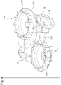
- Fig. 4 is a perspective view of the pump casing 18.
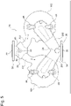
- Fig. 5 is a bottom view of the pump casing 18.
- Figs. 3 to 5 each illustrate the pump casing 18 in a state where the components other than the pump casing 18, namely, the first electric motor 101, the first rotary shaft 121, the first impeller 51, the second electric motor, the second rotary shaft, the second impeller 52, and the like are detached from the pump apparatus 16.
- the suction port 20 is provided in a suction flange 34.
- the suction flange 34 is to connect the pump casing 18 to a pipe.
- the discharge port 22 is provided in a discharge flange 36.
- the discharge flange 36 is to connect the pump casing 18 to a pipe.
- the pump casing 18 includes the first leg portion 38 provided in the suction branching portion 24, and the second leg portion 40 provided in the discharge merging portion 26.
- no leg portion is provided in the suction branching portion 24 and the discharge merging portion 26.
- the leg portions are provided in the first pump casing 181 and the second pump casing 182. The reason is because a bottom part of the first pump casing 181 and a bottom part of the second pump casing 182 are located at the lowest positions in the pump apparatus 16 as illustrated in Fig. 2 .
- vibration and noise of the pump apparatus 16 are reduced by the first leg portion 38 and the second leg portion 40, for the following reasons. Even in a case where only one of the pump apparatuses operates in the twin pump, vibration is inevitably transferred to the other pump apparatus. Therefore, an installation condition for suppression of vibration and noise is more difficult in the twin pump than in the single pump. In the case of the single pump, it is sufficient to suppress vibration and noise of one pump apparatus. In the case of the twin pump, however, vibration and noise conditions are complicated because of influence of vibration and noise from the other pump apparatus.
- the suction branching portion 24 and the discharge merging portion 26 serve as generation sources of vibration and noise. When the first leg portion 38 and the second leg portion 40 are respectively added to the suction branching portion 24 and the discharge merging portion 26, it is possible to reduce vibration and noise of the pump apparatus 16 as compared with the existing pump apparatus.
- At least one of the first leg portion 38 and the second leg portion 40 illustrated in Fig. 5 preferably includes a screw hole.
- the second leg portion 40 includes a screw hole 42.
- the screw hole 42 is used for various purposes.
- the screw hole 42 is used to install the pump apparatus 16. Further, the screw hole 42 is used when the pump casing 18 is placed on a processing tool and is upside down (pump casing 18 is hung down from processing tool) in manufacturing of the pump casing 18.
- At least one of the first leg portion 38 and the second leg portion 40 preferably includes a base part.
- the second leg portion 40 includes a base part 44.
- the base part 44 may be a flange.
- the base part 44 is provided in order to increase stability of an attachment state of the pump apparatus 16 when the pump apparatus 16 is installed or in manufacturing of the pump casing 18.
- a third leg portion is preferably provided in at least one of the first pump casing 181 and the second pump casing 182.
- two leg portions 46 are provided in the first pump casing 181
- two leg portions 48 are provided in the second pump casing 182.
- a fourth leg portion may be provided in at least one of the first discharge passage portion 221 and the second discharge passage portion 222.
- a fifth leg portion may be provided in at least one of the first suction passage portion 201 and the second suction passage portion 202.
Landscapes
- Engineering & Computer Science (AREA)
- Mechanical Engineering (AREA)
- General Engineering & Computer Science (AREA)
- Structures Of Non-Positive Displacement Pumps (AREA)
Abstract
Description
- The present invention relates to a pump casing.
- A pump apparatus is conventionally used for various applications in various kinds of houses and in a site such as a factory. For example, an inline pump in which a pump section and a motor section are integrated, and a suction port and a discharge port of a pump are arranged on the same line is widely used because the inline pump is easily attachable in a middle of a pipe. In a case where the inline pump is installed in a construction facility, it is desirable to avoid stoppage of liquid supply when one inline pump has failed or one inline pump is subjected to periodic inspection.
- To avoid stoppage of liquid supply, a case where two inline pumps are installed in parallel such that one of the inline pumps can back up the other inline pump is seen in markets in Europe. There is a product that is called a twin pump in which two inline pumps are arranged in parallel, one suction port and one discharge port are connected to the two inline pumps, and the two inline pumps share one suction port and one discharge port. Note that, in the following, in a case where the two inline pumps do not share one suction port and one discharge port, namely, in a case where each of the two inline pumps includes one suction port and one discharge port, each of the pumps is called a single pump.
- In the case where the twin pump is installed, if trouble occurs on one of the pumps, or the like, parts other than a casing of the pump having the trouble are detached, and an upper part of the casing is covered with a blank flange. Examples of the parts other than the casing include an electric motor disposed on the upper part of the casing, a rotary shaft coupled to the electric motor, and an impeller fixed to the rotary shaft and housed in the casing. In the twin pump, operation can be continued by the other pump during a pump maintenance period or during a period when a spare part for the failed pump is prepared.
- A product desirably saves space and has a long lifetime, and a pump manufacturer performs internal development in order to meet the demands. To meet the request, in a case of the twin pump, a length of a header pipe to branch a pipe into pipes for two single pumps or to merge pipes can be reduced as compared with a case where the two single pumps are arranged in parallel. Further, a valve such as a check valve for backflow prevention is shared by the two pumps configuring the twin pump, which makes it possible to achieve space saving. As a result, the twin pump manufacturer can meet space saving required by a customer. Further, alternately operating the two pumps configuring the twin pump makes it possible to simply double the pump lifetime.
- In a case where the single pump, namely, a pump in which two inline pumps are installed in parallel is manufactured, a horizontal surface of a portion where the pump comes into contact with a floor, for example, a pump bottom surface portion and a leg bottom surface portion is processed for each pump. Further, in a case where a single pump is installed, adjustment of a gap between a floor surface and the pump, and adjustment of a levelness of the pump are performed for each pump.
- In the case of the twin pump, however, pump casings for two pumps are integrally manufactured, and floor contact portions for the two pumps are also accordingly integrally manufactured. Therefore, horizontality of the floor contact portion for each pump is required in manufacturing and at installation, as well as mutual horizontality of the two pumps is required in manufacturing and at installation at the same time. Arrangement and process accuracy of the floor contact portions influence on self-standing ability at installation of the pump and a suppression degree of noise and vibration during operation of the pumps.
- PTL 1: International Publication No.
WO 2018/137019 - An aspect of the present invention is made to solve such issues, and an object thereof is to provide a pump casing improved in stability of installed pumps.
- To solve the above-described issues, according to a first aspect, a pump casing used for a pump apparatus to transfer a liquid, includes: a first pump casing; a first suction passage portion connected to the first pump casing; a first discharge passage portion connected to the first pump casing; a second pump casing; a second suction passage portion connected to the second pump casing; a second discharge passage portion connected to the second pump casing; a suction branching portion connected to the first suction passage portion and the second suction passage portion; a discharge merging portion connected to the first discharge passage portion and the second discharge passage portion; a first leg portion provided in the suction branching portion; and a second leg portion provided in the discharge merging portion.
- In the present aspect, the first leg portion is provided in the suction branching portion, and the second leg portion is provided in the discharge merging portion. Since the leg portions are provided in the suction branching portion and the discharge merging portion, stability of the pump casing is increased. Occurrence of noise and vibration during operation of pumps can be suppressed as compared with an existing pump casing. Therefore, it is possible to provide the pump casing improved in stability of the installed pumps.
- According to a second aspect, in the pump casing according to the first aspect, at least one of the first leg portion and the second leg portion includes a screw hole.
- According to a third aspect, in the pump casing according to the first or second aspect, at least one of the first leg portion and the second leg portion includes a base part.
- According to a fourth aspect, the pump casing according to any one of the first to third aspects further includes a third leg portion provided in at least one of the first pump casing and the second pump casing.
- According to a fifth aspect, the pump casing according to any one of the first to fourth aspects further includes a fourth leg portion provided in at least one of the first discharge passage portion and the second discharge passage portion.
- According to a sixth aspect, the pump casing according to any one of the first to fifth aspects further includes a fifth leg portion provided in at least one of the first suction passage portion and the second suction passage portion.
- According to a seventh aspect, a pump apparatus includes: a first electric motor; a first rotary shaft coupled to the first electric motor; a first impeller fixed to the first rotary shaft and housed in the first pump casing; a second electric motor; a second rotary shaft coupled to the second electric motor; a second impeller fixed to the second rotary shaft and housed in the second pump casing; and the pump casing according to any one of the first to sixth aspects.
-
Fig. 1 is a schematic view illustrating an embodiment of a pump casing; -
Fig. 2 is a schematic view illustrating an embodiment of a first pump apparatus; -
Fig. 3 is a top view of the pump casing; -
Fig. 4 is a perspective view of the pump casing; and -
Fig. 5 is a bottom view of the pump casing; - Some embodiments of the present invention are described below with reference to drawings. Note that, in the following embodiments, the same or equivalent members are denoted by the same reference numerals, and repetitive descriptions are omitted in some cases. Further, characteristics described in each of the embodiments are applicable to another embodiment without conflicting with each other.
-
Fig. 1 is a schematic view illustrating an embodiment of apump casing 18 according to the present invention. Thepump casing 18 is used for apump apparatus 16 to transfer a liquid. Onepump casing 18 includes afirst pump casing 181, a firstsuction passage portion 201 connected to thefirst pump casing 181, and a firstdischarge passage portion 221 connected to thefirst pump casing 181. Thepump casing 18 further includes asecond pump casing 182, a secondsuction passage portion 202 connected to thesecond pump casing 182, and a seconddischarge passage portion 222 connected to thesecond pump casing 182. - The
pump casing 18 further includes asuction branching portion 24 connected to the firstsuction passage portion 201 and the secondsuction passage portion 202, and adischarge merging portion 26 connected to the firstdischarge passage portion 221 and the seconddischarge passage portion 222. Thefirst pump casing 181, the firstsuction passage portion 201, the firstdischarge passage portion 221, thesecond pump casing 182, the secondsuction passage portion 202, the seconddischarge passage portion 222, thesuction branching portion 24, and thedischarge merging portion 26 are integrally formed as a casting. Some of these portions, for example, the firstdischarge passage portion 221, the seconddischarge passage portion 222, and thedischarge merging portion 26 may be manufactured as castings other than the other portions. - The
suction branching portion 24 corresponds to a section from asuction port 20 to a part branched to the firstsuction passage portion 201 and the secondsuction passage portion 202. More specifically, thesuction branching portion 24 corresponds to a section from thesuction port 20 to astart end part 58 of the firstsuction passage portion 201, and a section from thesuction port 20 to astart end part 60 of the secondsuction passage portion 202. Thedischarge merging portion 26 corresponds to a section from a part where the firstdischarge passage portion 221 and the seconddischarge passage portion 222 merge with each other to adischarge port 22. More specifically, thedischarge merging portion 26 corresponds to a section from aterminal end part 281 of the firstdischarge passage portion 221 to thedischarge port 22, and a section from aterminal end part 282 of the seconddischarge passage portion 222 to thedischarge port 22. Thesuction port 20 of thepump apparatus 16 is a connection portion between thepump apparatus 16 and a pipe (not illustrated) on a suction side of thepump apparatus 16. Thedischarge port 22 of thepump apparatus 16 is a connection portion between thepump apparatus 16 and a pipe (not illustrated) on a discharge side of thepump apparatus 16. - The
pump apparatus 16 includes afirst pump apparatus 161 and asecond pump apparatus 162. Thefirst pump apparatus 161 and thesecond pump apparatus 162 may have the same configuration or different configurations. In the present embodiment, thefirst pump apparatus 161 and thesecond pump apparatus 162 substantially have the same configuration. In other words, afirst impeller 51, thefirst pump casing 181, and the firstdischarge passage portion 221 respectively have the same dimensional shapes as asecond impeller 52, thesecond pump casing 182, and the seconddischarge passage portion 222. Arotation direction 54 of thefirst impeller 51 is the same as arotation direction 56 of thesecond impeller 52. On the other hand, the dimensional shape of the firstsuction passage portion 201 and the dimensional shape of the secondsuction passage portion 202 are slightly different from each other. - In the present embodiment, the
first pump apparatus 161 and thesecond pump apparatus 162 are centrifugal pumps; however, thefirst pump apparatus 161 and thesecond pump apparatus 162 are not limited to the centrifugal pumps as long as thefirst pump apparatus 161 and thesecond pump apparatus 162 are non-positive displacement pumps. In other words, thefirst pump apparatus 161 and thesecond pump apparatus 162 may be turbine pumps, axial-flow pumps, or mixed flow pumps. - Since the
first pump apparatus 161 and thesecond pump apparatus 162 substantially have the same configuration, the configuration of thefirst pump apparatus 161 is described with reference toFig. 2. Fig. 2 is a schematic view illustrating an embodiment of thefirst pump apparatus 161. Thefirst pump apparatus 161 includes a firstelectric motor 101, a firstrotary shaft 121 coupled to the firstelectric motor 101, and thefirst impeller 51 that is fixed to the firstrotary shaft 121 and is housed in thefirst pump casing 181. - Although not illustrated, the
second pump apparatus 162 also have a second electric motor, a second rotary shaft coupled to the second electric motor, and thesecond impeller 52 that is fixed to the second rotary shaft and is housed in thesecond pump casing 182, as with thefirst pump apparatus 161. - In the
first pump apparatus 161, thefirst impeller 51 is a centrifugal impeller. Therotary shaft 121 is rotatably supported by a bearing (not illustrated). Therotary shaft 121 and thefirst impeller 51 are integrally rotatable. Therotary shaft 121 and thefirst impeller 51 are rotated by theelectric motor 101. Aliner ring 102 is disposed around afluid inlet 51a of thefirst impeller 51. Theliner ring 102 is fixed to thefirst pump casing 181. - A
casing cover 122 is disposed between theelectric motor 101 and thefirst pump casing 181. An opening at an upper part of thefirst pump casing 181 is closed by thecasing cover 122. Theelectric motor 101 is fixed to thecasing cover 122. Thefirst pump casing 181 and thecasing cover 122 are formed as castings. Ashaft sealing device 15 sealing a gap between therotary shaft 121 and thecasing cover 122 is disposed on a rear side of thefirst impeller 51. Theshaft sealing device 15 is held by thecasing cover 122. Examples of theshaft sealing device 15 include a mechanical seal. The above-described blank flange (not illustrated) is disposed at a position of thecasing cover 122 at maintenance or the like. The blank flange is attached by using screw holes 62 (seeFig. 3 ) circumferentially arranged for attachment of thecasing cover 122. The blank flange has a disk shape, and includes, on an outer edge of the blank flange, attachment holes circumferentially arranged at positions corresponding to the screw holes 62. - The
pump casing 18 includes thesuction branching portion 24 including thesuction port 20, and thedischarge merging portion 26 including thedischarge port 22. Thefirst impeller 51 is disposed inside thefirst pump casing 181. Thesuction port 20 and thedischarge port 22 are arranged on one straight line. Thepump apparatus 16 in which thesuction port 20 and thedischarge port 22 are arranged on one straight line is called an inline pump apparatus. In the present embodiment, two inline pumps are arranged in parallel, one suction port and one discharge port are connected to the two inline pumps, and the two inline pumps share one suction port and one discharge port. When the two inline pumps share one suction port and one discharge port, these pumps configure one twin pump as a whole. Thepump casing 18 includes afirst leg portion 38 provided in thesuction branching portion 24, and asecond leg portion 40 provided in thedischarge merging portion 26. - A difference between one inline pump as a twin pump and two inline pumps (two single pumps) arranged in parallel is described. In the two single pumps arranged in parallel, discharge ports of the single pumps are connected to respective pipes on a discharge side, and the two pipes are then merged to form one pipe on a downstream side. Further, on a suction side, one pipe is branched into two pipes, and the two pipes are connected to suction ports of the respective single pumps. In contrast, in the twin pump, two discharge passage portions are merged at the
discharge merging portion 26 on the discharge side, and the merged passage portion is connected to a pipe at thedischarge port 22 of the twin pump. Further, on the suction side of the twin pump, a pipe is connected to thesuction port 20 of the pump, and is then branched into two suction passage portions through thesuction branching portion 24. - When the
electric motor 101 rotates thefirst impeller 51, the liquid flows into thepump casing 18 from thesuction port 20. More specifically, the liquid flows into the firstsuction passage portion 201 from thesuction port 20, and then flows into thefluid inlet 51a of thefirst impeller 51 through the firstsuction passage portion 201. The rotatingfirst impeller 51 applies velocity energy to the liquid, and the velocity energy of the liquid flowing through thefirst pump casing 181 is converted into pressure. The pressurized liquid is discharged from thepump casing 18 through thedischarge port 22. - Various methods of operating the
first pump apparatus 161 and thesecond pump apparatus 162 are usable. A method of operating only one of thefirst pump apparatus 161 and thesecond pump apparatus 162 and stopping the other pump apparatus, or a method of operating both of thefirst pump apparatus 161 and thesecond pump apparatus 162 at the same time is usable. As illustrated inFig. 1 , thedischarge merging portion 26 includes an on-offvalve 28. The on-offvalve 28 closes the discharge passage portion connected to the stopped pump apparatus based on operation states of thefirst pump apparatus 161 and thesecond pump apparatus 162. - For example, when the
first pump apparatus 161 operates and thesecond pump apparatus 162 stops, the on-offvalve 28 is moved to aposition 282 illustrated by a dotted line by hydraulic pressure from the firstdischarge passage portion 221, to close the seconddischarge passage portion 222. When thesecond pump apparatus 162 operates and thefirst pump apparatus 161 stops, the on-offvalve 28 is moved to aposition 281 illustrated by a dashed line by hydraulic pressure from the seconddischarge passage portion 222, to close the firstdischarge passage portion 221. When thefirst pump apparatus 161 and thesecond pump apparatus 162 both operate at the same time, the on-offvalve 28 is moved to anintermediate position 283 illustrated by a solid line by hydraulic pressure from the firstdischarge passage portion 221 and hydraulic pressure from the seconddischarge passage portion 222. -
Figs. 3 to 5 each illustrate a configuration of thesingle pump casing 18.Fig. 3 is a top view of thepump casing 18.Fig. 4 is a perspective view of thepump casing 18.Fig. 5 is a bottom view of thepump casing 18.Figs. 3 to 5 each illustrate thepump casing 18 in a state where the components other than thepump casing 18, namely, the firstelectric motor 101, the firstrotary shaft 121, thefirst impeller 51, the second electric motor, the second rotary shaft, thesecond impeller 52, and the like are detached from thepump apparatus 16. Thesuction port 20 is provided in asuction flange 34. Thesuction flange 34 is to connect thepump casing 18 to a pipe. Thedischarge port 22 is provided in adischarge flange 36. Thedischarge flange 36 is to connect thepump casing 18 to a pipe. - As illustrated in
Fig. 5 , thepump casing 18 includes thefirst leg portion 38 provided in thesuction branching portion 24, and thesecond leg portion 40 provided in thedischarge merging portion 26. In the existing pump casing, no leg portion is provided in thesuction branching portion 24 and thedischarge merging portion 26. In the existing pump casing, the leg portions are provided in thefirst pump casing 181 and thesecond pump casing 182. The reason is because a bottom part of thefirst pump casing 181 and a bottom part of thesecond pump casing 182 are located at the lowest positions in thepump apparatus 16 as illustrated inFig. 2 . - It is expected that vibration and noise of the
pump apparatus 16 are reduced by thefirst leg portion 38 and thesecond leg portion 40, for the following reasons. Even in a case where only one of the pump apparatuses operates in the twin pump, vibration is inevitably transferred to the other pump apparatus. Therefore, an installation condition for suppression of vibration and noise is more difficult in the twin pump than in the single pump. In the case of the single pump, it is sufficient to suppress vibration and noise of one pump apparatus. In the case of the twin pump, however, vibration and noise conditions are complicated because of influence of vibration and noise from the other pump apparatus. Thesuction branching portion 24 and thedischarge merging portion 26 serve as generation sources of vibration and noise. When thefirst leg portion 38 and thesecond leg portion 40 are respectively added to thesuction branching portion 24 and thedischarge merging portion 26, it is possible to reduce vibration and noise of thepump apparatus 16 as compared with the existing pump apparatus. - At least one of the
first leg portion 38 and thesecond leg portion 40 illustrated inFig. 5 preferably includes a screw hole. In the present embodiment, thesecond leg portion 40 includes ascrew hole 42. Thescrew hole 42 is used for various purposes. Thescrew hole 42 is used to install thepump apparatus 16. Further, thescrew hole 42 is used when thepump casing 18 is placed on a processing tool and is upside down (pump casing 18 is hung down from processing tool) in manufacturing of thepump casing 18. - At least one of the
first leg portion 38 and thesecond leg portion 40 preferably includes a base part. In the present embodiment, thesecond leg portion 40 includes abase part 44. Thebase part 44 may be a flange. Thebase part 44 is provided in order to increase stability of an attachment state of thepump apparatus 16 when thepump apparatus 16 is installed or in manufacturing of thepump casing 18. - A third leg portion is preferably provided in at least one of the
first pump casing 181 and thesecond pump casing 182. In the present embodiment, as illustrated inFig. 5 , twoleg portions 46 are provided in thefirst pump casing 181, and twoleg portions 48 are provided in thesecond pump casing 182. - A fourth leg portion may be provided in at least one of the first
discharge passage portion 221 and the seconddischarge passage portion 222. A fifth leg portion may be provided in at least one of the firstsuction passage portion 201 and the secondsuction passage portion 202. - Although the exemplary embodiments of the present invention are described above, the above-described embodiments of the present invention are to facilitate understanding of the present invention, and do not limit the present invention. Needless to say, the present invention can be modified and improved without departing from the spirit of the present invention, and includes equivalents thereof. Further, the components described in the claims and the specification can be optionally combined or omitted within a range where at least a part of the above-described issues is solved or within a range where at least a part of the effects is achieved.
- 16
- Pump apparatus
- 18
- Pump casing
- 20
- Suction port
- 22
- Discharge port
- 24
- Suction branching portion
- 26
- Discharge merging portion
- 28
- On-off valve
- 34
- Suction flange
- 36
- Discharge flange
- 38
- First leg portion
- 40
- Second leg portion
- 42
- Screw hole
- 44
- Base part
- 46
- Leg portion
- 48
- Leg portion
- 51
- First impeller
- 52
- Second impeller
- 101
- Electric motor
- 101
- First electric motor
- 121
- Rotary shaft
- 121
- First rotary shaft
- 161
- First pump apparatus
- 162
- Second pump apparatus
- 181
- Pump casing
- 181
- First pump casing
- 182
- Second pump casing
- 201
- First suction passage portion
- 202
- Second suction passage portion
- 221
- First discharge passage portion
- 222
- Second discharge passage portion
Claims (7)
- A pump casing used for a pump apparatus to transfer a liquid, the pump casing comprising:a first pump casing;a first suction passage portion connected to the first pump casing;a first discharge passage portion connected to the first pump casing;a second pump casing;a second suction passage portion connected to the second pump casing;a second discharge passage portion connected to the second pump casing;a suction branching portion connected to the first suction passage portion and the second suction passage portion;a discharge merging portion connected to the first discharge passage portion and the second discharge passage portion;a first leg portion provided in the suction branching portion; anda second leg portion provided in the discharge merging portion.
- The pump casing according to claim 1, wherein at least one of the first leg portion and the second leg portion includes a screw hole.
- The pump casing according to claim 1 or 2, wherein at least one of the first leg portion and the second leg portion includes a base part.
- The pump casing according to any one of claims 1 to 3, further comprising a third leg portion provided in at least one of the first pump casing and the second pump casing.
- The pump casing according to any one of claims 1 to 4, further comprising a fourth leg portion provided in at least one of the first discharge passage portion and the second discharge passage portion.
- The pump casing according to any one of claims 1 to 5, further comprising a fifth leg portion provided in at least one of the first suction passage portion and the second suction passage portion.
- A pump apparatus, comprising:a first electric motor;a first rotary shaft coupled to the first electric motor;a first impeller fixed to the first rotary shaft and housed in the first pump casing;a second electric motor;a second rotary shaft coupled to the second electric motor;a second impeller fixed to the second rotary shaft and housed in the second pump casing; andthe pump casing according to any one of claims 1 to 6.
Applications Claiming Priority (1)
| Application Number | Priority Date | Filing Date | Title |
|---|---|---|---|
| JP2021095054A JP7608277B2 (en) | 2021-06-07 | 2021-06-07 | Pump casing |
Publications (1)
| Publication Number | Publication Date |
|---|---|
| EP4102077A1 true EP4102077A1 (en) | 2022-12-14 |
Family
ID=81877846
Family Applications (1)
| Application Number | Title | Priority Date | Filing Date |
|---|---|---|---|
| EP22177047.2A Pending EP4102077A1 (en) | 2021-06-07 | 2022-06-02 | Pump casing |
Country Status (2)
| Country | Link |
|---|---|
| EP (1) | EP4102077A1 (en) |
| JP (1) | JP7608277B2 (en) |
Citations (4)
| Publication number | Priority date | Publication date | Assignee | Title |
|---|---|---|---|---|
| EP3171036A1 (en) * | 2015-11-19 | 2017-05-24 | Adwatec Oy | Liquid cooling station |
| WO2018137019A1 (en) | 2017-01-27 | 2018-08-02 | S. A. Armstrong Limited | Dual body variable duty performance optimizing pump unit |
| US20190063441A1 (en) * | 2017-08-29 | 2019-02-28 | Cornell Pump Company | Dual pump system |
| WO2019244590A1 (en) * | 2018-06-22 | 2019-12-26 | 株式会社荏原製作所 | Double suction volute pump |
Family Cites Families (2)
| Publication number | Priority date | Publication date | Assignee | Title |
|---|---|---|---|---|
| JP4763887B2 (en) | 2000-12-04 | 2011-08-31 | 株式会社川本製作所 | Direct connection type automatic water supply device |
| JP7312558B2 (en) | 2018-07-23 | 2023-07-21 | 株式会社荏原製作所 | Water supply device |
-
2021
- 2021-06-07 JP JP2021095054A patent/JP7608277B2/en active Active
-
2022
- 2022-06-02 EP EP22177047.2A patent/EP4102077A1/en active Pending
Patent Citations (4)
| Publication number | Priority date | Publication date | Assignee | Title |
|---|---|---|---|---|
| EP3171036A1 (en) * | 2015-11-19 | 2017-05-24 | Adwatec Oy | Liquid cooling station |
| WO2018137019A1 (en) | 2017-01-27 | 2018-08-02 | S. A. Armstrong Limited | Dual body variable duty performance optimizing pump unit |
| US20190063441A1 (en) * | 2017-08-29 | 2019-02-28 | Cornell Pump Company | Dual pump system |
| WO2019244590A1 (en) * | 2018-06-22 | 2019-12-26 | 株式会社荏原製作所 | Double suction volute pump |
Also Published As
| Publication number | Publication date |
|---|---|
| JP2022187179A (en) | 2022-12-19 |
| JP7608277B2 (en) | 2025-01-06 |
Similar Documents
| Publication | Publication Date | Title |
|---|---|---|
| KR960001994B1 (en) | Electric combined pump device | |
| US9239056B2 (en) | Pump impeller and submersible pump having such pump impeller | |
| US20100028156A1 (en) | Impeller and pump including the same | |
| GB2290113A (en) | Centrifugal pump shaft seal cooling and venting | |
| EP4102077A1 (en) | Pump casing | |
| JP2011208558A (en) | Centrifugal fluid machine | |
| US10890105B2 (en) | Exhaust gas turbocharger | |
| EP4102076A1 (en) | Pump casing | |
| JP2001073993A (en) | Centrifugal fluid machinery | |
| CN101952557A (en) | Rotary mechanism | |
| JP7108555B2 (en) | compressor | |
| JP7001161B2 (en) | Supercharger | |
| JP6758358B2 (en) | pump | |
| EP3421808B1 (en) | Rotary compressor machine | |
| KR102627725B1 (en) | Vibration reduction pump | |
| JPWO2018030179A1 (en) | Turbocharger | |
| JP7588658B2 (en) | Canned motor pump and piping method thereof | |
| JPH0674197A (en) | Pump casing made of sheet metal | |
| US8403625B2 (en) | Pitot tube pump | |
| JPH11280694A (en) | Centrifugal compressor | |
| US20260071631A1 (en) | Shut-off valve and vacuum pump | |
| JP2022029203A (en) | Centrifugal compressor | |
| KR100723907B1 (en) | Inline 2-Way Pump | |
| JP3210635B2 (en) | Canned motor and pump using the canned motor | |
| CN215486638U (en) | Single-stage single-suction pipeline centrifugal pump |
Legal Events
| Date | Code | Title | Description |
|---|---|---|---|
| PUAI | Public reference made under article 153(3) epc to a published international application that has entered the european phase |
Free format text: ORIGINAL CODE: 0009012 |
|
| STAA | Information on the status of an ep patent application or granted ep patent |
Free format text: STATUS: THE APPLICATION HAS BEEN PUBLISHED |
|
| AK | Designated contracting states |
Kind code of ref document: A1 Designated state(s): AL AT BE BG CH CY CZ DE DK EE ES FI FR GB GR HR HU IE IS IT LI LT LU LV MC MK MT NL NO PL PT RO RS SE SI SK SM TR |
|
| STAA | Information on the status of an ep patent application or granted ep patent |
Free format text: STATUS: REQUEST FOR EXAMINATION WAS MADE |
|
| 17P | Request for examination filed |
Effective date: 20230614 |
|
| RBV | Designated contracting states (corrected) |
Designated state(s): AL AT BE BG CH CY CZ DE DK EE ES FI FR GB GR HR HU IE IS IT LI LT LU LV MC MK MT NL NO PL PT RO RS SE SI SK SM TR |
|
| RAP3 | Party data changed (applicant data changed or rights of an application transferred) |
Owner name: EBARA CORPORATION |
|
| STAA | Information on the status of an ep patent application or granted ep patent |
Free format text: STATUS: EXAMINATION IS IN PROGRESS |
|
| 17Q | First examination report despatched |
Effective date: 20240524 |
|
| GRAP | Despatch of communication of intention to grant a patent |
Free format text: ORIGINAL CODE: EPIDOSNIGR1 |
|
| STAA | Information on the status of an ep patent application or granted ep patent |
Free format text: STATUS: GRANT OF PATENT IS INTENDED |
|
| INTG | Intention to grant announced |
Effective date: 20260120 |