EP4102042A1 - Dual-pressure source aircraft pneumatic system with pressure relief - Google Patents
Dual-pressure source aircraft pneumatic system with pressure relief Download PDFInfo
- Publication number
- EP4102042A1 EP4102042A1 EP22177474.8A EP22177474A EP4102042A1 EP 4102042 A1 EP4102042 A1 EP 4102042A1 EP 22177474 A EP22177474 A EP 22177474A EP 4102042 A1 EP4102042 A1 EP 4102042A1
- Authority
- EP
- European Patent Office
- Prior art keywords
- pressure
- bleed
- low
- compressed air
- duct
- Prior art date
- Legal status (The legal status is an assumption and is not a legal conclusion. Google has not performed a legal analysis and makes no representation as to the accuracy of the status listed.)
- Pending
Links
- 238000011144 upstream manufacturing Methods 0.000 claims abstract description 71
- 230000001105 regulatory effect Effects 0.000 claims abstract description 43
- 230000007613 environmental effect Effects 0.000 claims description 9
- 239000007789 gas Substances 0.000 description 21
- 230000008901 benefit Effects 0.000 description 7
- 238000000034 method Methods 0.000 description 7
- 239000000567 combustion gas Substances 0.000 description 4
- 230000004044 response Effects 0.000 description 3
- 239000000284 extract Substances 0.000 description 2
- 239000000446 fuel Substances 0.000 description 2
- 230000006870 function Effects 0.000 description 2
- 238000012986 modification Methods 0.000 description 2
- 230000004048 modification Effects 0.000 description 2
- 230000008569 process Effects 0.000 description 2
- 230000001902 propagating effect Effects 0.000 description 2
- 230000000740 bleeding effect Effects 0.000 description 1
- 238000009530 blood pressure measurement Methods 0.000 description 1
- 230000008859 change Effects 0.000 description 1
- 238000002485 combustion reaction Methods 0.000 description 1
- 238000004891 communication Methods 0.000 description 1
- 230000006835 compression Effects 0.000 description 1
- 238000007906 compression Methods 0.000 description 1
- 230000001143 conditioned effect Effects 0.000 description 1
- 230000001276 controlling effect Effects 0.000 description 1
- 230000008878 coupling Effects 0.000 description 1
- 238000010168 coupling process Methods 0.000 description 1
- 238000005859 coupling reaction Methods 0.000 description 1
- 238000013461 design Methods 0.000 description 1
- 238000004519 manufacturing process Methods 0.000 description 1
- 239000000463 material Substances 0.000 description 1
- 230000007246 mechanism Effects 0.000 description 1
Images


Classifications
-
- B—PERFORMING OPERATIONS; TRANSPORTING
- B64—AIRCRAFT; AVIATION; COSMONAUTICS
- B64D—EQUIPMENT FOR FITTING IN OR TO AIRCRAFT; FLIGHT SUITS; PARACHUTES; ARRANGEMENT OR MOUNTING OF POWER PLANTS OR PROPULSION TRANSMISSIONS IN AIRCRAFT
- B64D13/00—Arrangements or adaptations of air-treatment apparatus for aircraft crew or passengers, or freight space
- B64D13/06—Arrangements or adaptations of air-treatment apparatus for aircraft crew or passengers, or freight space the air being conditioned
-
- B—PERFORMING OPERATIONS; TRANSPORTING
- B64—AIRCRAFT; AVIATION; COSMONAUTICS
- B64D—EQUIPMENT FOR FITTING IN OR TO AIRCRAFT; FLIGHT SUITS; PARACHUTES; ARRANGEMENT OR MOUNTING OF POWER PLANTS OR PROPULSION TRANSMISSIONS IN AIRCRAFT
- B64D15/00—De-icing or preventing icing on exterior surfaces of aircraft
- B64D15/02—De-icing or preventing icing on exterior surfaces of aircraft by ducted hot gas or liquid
- B64D15/04—Hot gas application
-
- F—MECHANICAL ENGINEERING; LIGHTING; HEATING; WEAPONS; BLASTING
- F01—MACHINES OR ENGINES IN GENERAL; ENGINE PLANTS IN GENERAL; STEAM ENGINES
- F01D—NON-POSITIVE DISPLACEMENT MACHINES OR ENGINES, e.g. STEAM TURBINES
- F01D17/00—Regulating or controlling by varying flow
- F01D17/10—Final actuators
- F01D17/105—Final actuators by passing part of the fluid
-
- F—MECHANICAL ENGINEERING; LIGHTING; HEATING; WEAPONS; BLASTING
- F01—MACHINES OR ENGINES IN GENERAL; ENGINE PLANTS IN GENERAL; STEAM ENGINES
- F01D—NON-POSITIVE DISPLACEMENT MACHINES OR ENGINES, e.g. STEAM TURBINES
- F01D21/00—Shutting-down of machines or engines, e.g. in emergency; Regulating, controlling, or safety means not otherwise provided for
- F01D21/003—Arrangements for testing or measuring
-
- F—MECHANICAL ENGINEERING; LIGHTING; HEATING; WEAPONS; BLASTING
- F02—COMBUSTION ENGINES; HOT-GAS OR COMBUSTION-PRODUCT ENGINE PLANTS
- F02C—GAS-TURBINE PLANTS; AIR INTAKES FOR JET-PROPULSION PLANTS; CONTROLLING FUEL SUPPLY IN AIR-BREATHING JET-PROPULSION PLANTS
- F02C6/00—Plural gas-turbine plants; Combinations of gas-turbine plants with other apparatus; Adaptations of gas-turbine plants for special use
- F02C6/04—Gas-turbine plants providing heated or pressurised working fluid for other apparatus, e.g. without mechanical power output
- F02C6/06—Gas-turbine plants providing heated or pressurised working fluid for other apparatus, e.g. without mechanical power output providing compressed gas
- F02C6/08—Gas-turbine plants providing heated or pressurised working fluid for other apparatus, e.g. without mechanical power output providing compressed gas the gas being bled from the gas-turbine compressor
-
- F—MECHANICAL ENGINEERING; LIGHTING; HEATING; WEAPONS; BLASTING
- F02—COMBUSTION ENGINES; HOT-GAS OR COMBUSTION-PRODUCT ENGINE PLANTS
- F02C—GAS-TURBINE PLANTS; AIR INTAKES FOR JET-PROPULSION PLANTS; CONTROLLING FUEL SUPPLY IN AIR-BREATHING JET-PROPULSION PLANTS
- F02C7/00—Features, components parts, details or accessories, not provided for in, or of interest apart form groups F02C1/00 - F02C6/00; Air intakes for jet-propulsion plants
- F02C7/04—Air intakes for gas-turbine plants or jet-propulsion plants
- F02C7/047—Heating to prevent icing
-
- F—MECHANICAL ENGINEERING; LIGHTING; HEATING; WEAPONS; BLASTING
- F02—COMBUSTION ENGINES; HOT-GAS OR COMBUSTION-PRODUCT ENGINE PLANTS
- F02C—GAS-TURBINE PLANTS; AIR INTAKES FOR JET-PROPULSION PLANTS; CONTROLLING FUEL SUPPLY IN AIR-BREATHING JET-PROPULSION PLANTS
- F02C9/00—Controlling gas-turbine plants; Controlling fuel supply in air- breathing jet-propulsion plants
- F02C9/16—Control of working fluid flow
- F02C9/18—Control of working fluid flow by bleeding, bypassing or acting on variable working fluid interconnections between turbines or compressors or their stages
-
- B—PERFORMING OPERATIONS; TRANSPORTING
- B64—AIRCRAFT; AVIATION; COSMONAUTICS
- B64D—EQUIPMENT FOR FITTING IN OR TO AIRCRAFT; FLIGHT SUITS; PARACHUTES; ARRANGEMENT OR MOUNTING OF POWER PLANTS OR PROPULSION TRANSMISSIONS IN AIRCRAFT
- B64D13/00—Arrangements or adaptations of air-treatment apparatus for aircraft crew or passengers, or freight space
- B64D13/06—Arrangements or adaptations of air-treatment apparatus for aircraft crew or passengers, or freight space the air being conditioned
- B64D2013/0603—Environmental Control Systems
- B64D2013/0618—Environmental Control Systems with arrangements for reducing or managing bleed air, using another air source, e.g. ram air
-
- F—MECHANICAL ENGINEERING; LIGHTING; HEATING; WEAPONS; BLASTING
- F05—INDEXING SCHEMES RELATING TO ENGINES OR PUMPS IN VARIOUS SUBCLASSES OF CLASSES F01-F04
- F05D—INDEXING SCHEME FOR ASPECTS RELATING TO NON-POSITIVE-DISPLACEMENT MACHINES OR ENGINES, GAS-TURBINES OR JET-PROPULSION PLANTS
- F05D2220/00—Application
- F05D2220/30—Application in turbines
- F05D2220/32—Application in turbines in gas turbines
- F05D2220/323—Application in turbines in gas turbines for aircraft propulsion, e.g. jet engines
-
- F—MECHANICAL ENGINEERING; LIGHTING; HEATING; WEAPONS; BLASTING
- F05—INDEXING SCHEMES RELATING TO ENGINES OR PUMPS IN VARIOUS SUBCLASSES OF CLASSES F01-F04
- F05D—INDEXING SCHEME FOR ASPECTS RELATING TO NON-POSITIVE-DISPLACEMENT MACHINES OR ENGINES, GAS-TURBINES OR JET-PROPULSION PLANTS
- F05D2260/00—Function
- F05D2260/60—Fluid transfer
- F05D2260/605—Venting into the ambient atmosphere or the like
-
- F—MECHANICAL ENGINEERING; LIGHTING; HEATING; WEAPONS; BLASTING
- F05—INDEXING SCHEMES RELATING TO ENGINES OR PUMPS IN VARIOUS SUBCLASSES OF CLASSES F01-F04
- F05D—INDEXING SCHEME FOR ASPECTS RELATING TO NON-POSITIVE-DISPLACEMENT MACHINES OR ENGINES, GAS-TURBINES OR JET-PROPULSION PLANTS
- F05D2260/00—Function
- F05D2260/60—Fluid transfer
- F05D2260/606—Bypassing the fluid
-
- F—MECHANICAL ENGINEERING; LIGHTING; HEATING; WEAPONS; BLASTING
- F05—INDEXING SCHEMES RELATING TO ENGINES OR PUMPS IN VARIOUS SUBCLASSES OF CLASSES F01-F04
- F05D—INDEXING SCHEME FOR ASPECTS RELATING TO NON-POSITIVE-DISPLACEMENT MACHINES OR ENGINES, GAS-TURBINES OR JET-PROPULSION PLANTS
- F05D2260/00—Function
- F05D2260/80—Diagnostics
-
- F—MECHANICAL ENGINEERING; LIGHTING; HEATING; WEAPONS; BLASTING
- F05—INDEXING SCHEMES RELATING TO ENGINES OR PUMPS IN VARIOUS SUBCLASSES OF CLASSES F01-F04
- F05D—INDEXING SCHEME FOR ASPECTS RELATING TO NON-POSITIVE-DISPLACEMENT MACHINES OR ENGINES, GAS-TURBINES OR JET-PROPULSION PLANTS
- F05D2270/00—Control
- F05D2270/30—Control parameters, e.g. input parameters
- F05D2270/301—Pressure
-
- F—MECHANICAL ENGINEERING; LIGHTING; HEATING; WEAPONS; BLASTING
- F05—INDEXING SCHEMES RELATING TO ENGINES OR PUMPS IN VARIOUS SUBCLASSES OF CLASSES F01-F04
- F05D—INDEXING SCHEME FOR ASPECTS RELATING TO NON-POSITIVE-DISPLACEMENT MACHINES OR ENGINES, GAS-TURBINES OR JET-PROPULSION PLANTS
- F05D2270/00—Control
- F05D2270/40—Type of control system
- F05D2270/44—Type of control system active, predictive, or anticipative
-
- F—MECHANICAL ENGINEERING; LIGHTING; HEATING; WEAPONS; BLASTING
- F05—INDEXING SCHEMES RELATING TO ENGINES OR PUMPS IN VARIOUS SUBCLASSES OF CLASSES F01-F04
- F05D—INDEXING SCHEME FOR ASPECTS RELATING TO NON-POSITIVE-DISPLACEMENT MACHINES OR ENGINES, GAS-TURBINES OR JET-PROPULSION PLANTS
- F05D2270/00—Control
- F05D2270/50—Control logic embodiments
-
- F—MECHANICAL ENGINEERING; LIGHTING; HEATING; WEAPONS; BLASTING
- F05—INDEXING SCHEMES RELATING TO ENGINES OR PUMPS IN VARIOUS SUBCLASSES OF CLASSES F01-F04
- F05D—INDEXING SCHEME FOR ASPECTS RELATING TO NON-POSITIVE-DISPLACEMENT MACHINES OR ENGINES, GAS-TURBINES OR JET-PROPULSION PLANTS
- F05D2270/00—Control
- F05D2270/80—Devices generating input signals, e.g. transducers, sensors, cameras or strain gauges
Definitions
- the present disclosure relates generally to aircraft pneumatic systems and, more particularly, to bleed air systems configured to bleed air from a compressor section of a gas turbine engine.
- Gas turbine engines of the turbofan, turbojet and turboprop types typically include a compressor section, a combustor section and a turbine section.
- air is pressurized in the compressor section and is mixed with fuel and burned in the combustor section to generate hot combustion gases.
- the hot combustion gases flow through the turbine section, which extracts energy from the hot combustion gases to power the compressor section and other gas turbine engine loads, such as those required to rotate fan blades in a fan section of a turbofan engine, where the fan section drives air along a bypass flow path.
- the compressor section typically includes low-pressure and high-pressure compressors
- the turbine section includes low-pressure and high-pressure turbines.
- bleed air extracted from the main engines to supply conditioned air to various pneumatic systems, such as, for example, deicing or anti-icing systems or environmental control systems.
- the air extracted from the main engines is supplied to and controlled by a bleed air system.
- the bleed air system is typically comprised of a series of valves, ducting and a pre-cooler, and extracts air from different ports of the compressor section of a gas turbine engine. This high-pressure and high temperature air may then be regulated or cooled before it is delivered downstream to the aircraft pneumatic systems.
- a bleed air system for a pneumatic system of an aircraft.
- the bleed air system includes: a low-pressure bleed tap configured to bleed a low-pressure compressed air from a low-pressure source; a high-pressure bleed tap configured to bleed a high-pressure compressed air from a high-pressure source; an upstream duct configured to receive one or both of the low-pressure compressed air and the high-pressure compressed air; a downstream duct configured to provide a regulated compressed air to the pneumatic system; a high-pressure shutoff valve positioned between the high-pressure bleed tap and the upstream duct; a low-pressure non-return valve positioned between the low-pressure bleed tap and the upstream duct; a pressure regulating and shutoff valve positioned between the upstream duct and the downstream duct, the pressure regulating and shutoff valve configured to generate the regulated compressed air; and a pressure relief valve positioned within the upstream duct.
- the high-pressure shutoff valve includes one or more bleed orifices configured to allow a bypass flow to pass through the high-pressure shutoff valve when in a closed position during a non-operational state of the bleed air system and while the aircraft is in an operational state.
- the one or more bleed orifices is configured to maintain an upstream duct pressure of a compressed air in the upstream duct to be lower than the pressure of the high-pressure compressed air at the high-pressure bleed tap and higher than the pressure of the low-pressure compressed air at the low-pressure bleed tap during the non-operational state.
- the low-pressure non-return valve is constrained from movement via the upstream duct pressure of the compressed air in the upstream duct during the non-operational state.
- the pressure relief valve is integrated into at least one of the high-pressure shutoff valve or the low-pressure non-return valve. In various optional embodiments, the pressure relief valve is configured to exhaust the compressed air to the atmosphere or to a location along the downstream duct, downstream of the pressure regulating and shutoff valve via a bypass duct. In various optional embodiments, the pressure relief valve is a self-regulating pressure relief valve. In various optional embodiments, the pressure relief valve is an actively controlled pressure relief valve.
- a downstream pressure transducer is configured to monitor a downstream duct pressure of a compressed air in the downstream duct.
- an upstream pressure transducer is configured to monitor an upstream duct pressure of a compressed air in the upstream duct.
- a controller is operatively connected to the upstream pressure transducer and configured to detect a failure of one or more of the high-pressure shutoff valve, the pressure regulating and shutoff valve and the pressure relief valve based on an input signal received from the upstream pressure transducer and to regulate the downstream duct pressure of the compressed air in the downstream duct.
- the low-pressure source is one of a low-pressure compressor or a high-pressure compressor.
- the high-pressure source is one of the low-pressure compressor or the high-pressure compressor.
- the pneumatic system is one of an anti-icing system or an environmental control system.
- a gas turbine engine in another aspect, includes: a low-pressure compressor; a high-pressure compressor; and a bleed air system, the bleed air system including a low-pressure bleed tap configured to bleed a low-pressure compressed air from the low-pressure compressor or the high-pressure compressor, a high-pressure bleed tap configured to bleed a high-pressure compressed air from the low-pressure compressor or the high-pressure compressor, an upstream duct configured to receive one or both of the low-pressure compressed air and the high-pressure compressed air, a downstream duct configured to provide a regulated compressed air to a pneumatic system, a high-pressure shutoff valve positioned between the high-pressure bleed tap and the upstream duct, a low-pressure non-return valve positioned between the low-pressure bleed tap and the upstream duct, a pressure regulating and shutoff valve positioned between the upstream duct and the downstream duct, the pressure regulating and shutoff valve configured to generate the regulated compressed air, and a pressure relief valve
- the high-pressure shutoff valve includes one or more bleed orifices configured to allow a bypass flow to pass through the high-pressure shutoff valve when in a closed position during a non-operational state of the bleed air system and while the gas turbine engine is in an operational state.
- the one or more bleed orifices is configured to maintain an upstream duct pressure of a compressed air in the upstream duct to be lower than the pressure of the high-pressure compressed air at the high-pressure bleed tap and higher than the pressure of the low-pressure compressed air at the low-pressure bleed tap during the non-operational state.
- the pressure relief valve is integrated into one at least one of the high-pressure shutoff valve and the low-pressure non-return valve.
- a downstream pressure transducer is configured to monitor a downstream duct pressure in the downstream duct and an upstream pressure transducer configured to monitor the upstream duct pressure in the upstream duct.
- a controller is operatively connected to the upstream pressure transducer and configured to detect a failure of one or more of the high-pressure shutoff valve, the pressure regulating and shutoff valve and the pressure relief valve based on an input signal received from the upstream pressure transducer and to regulate the downstream duct pressure of the compressed air in the downstream duct.
- references to "a,” “an” or “the” may include one or more than one and that reference to an item in the singular may also include the item in the plural. Further, all ranges may include upper and lower values and all ranges and ratio limits disclosed herein may be combined.
- FIG. 1A schematically illustrates an aircraft 10, in accordance with various embodiments.
- the aircraft 10 generally includes a fuselage 12 extending the length of the aircraft 10.
- a wing 14 is attached to and extends from respective sides of the fuselage 12.
- a gas turbine engine 16 is likewise attached to and extends from respective sides of the fuselage 12.
- the gas turbine engine 16 is attached to the fuselage 12 via a pylon 18.
- the gas turbine engine 16 includes a fan cowl assembly 20, an inlet section 22 and a thrust reverser 24.
- the gas turbine engine 16 includes an anti-icing system 26 (or a deicing system) for the nacelle inlet and the wing 14 includes an anti-icing system 28 (or a deicing system) for the leading edge.
- FIG. 1A depicts the gas turbine engine 16 as being attached to the side of the fuselage 12, the disclosure contemplates, without loss of generality, the gas turbine engine 16 being attached to an underside of the wing 14. The concepts described by the disclosure are the same regardless of where the gas turbine engine 16 is located on or how the gas turbine engine 16 is otherwise attached to the aircraft 10.
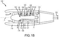
- FIG. 1B schematically illustrates a gas turbine engine 100 of the turbofan variety, similar to the gas turbine engine 16 described above with reference to FIG. 1A .
- the gas turbine engine 100 generally includes a fan section 102 and a core engine section 104, which includes a compressor section 106, a combustor section 108 and a turbine section 110.
- the fan section 102 drives air along a bypass flow path B in a bypass duct 112 defined within a radially inner surface 114 of a nacelle 116 and an outer casing 117 of the core engine section 104, while the compressor section 106 drives air along a core flow path C of the core engine section 104 for compression and communication into the combustor section 108 and then expansion through the turbine section 110.
- the core engine section 104 may generally include a low-speed spool and a high-speed spool mounted for rotation about a central longitudinal axis A.
- the low-speed spool generally includes an inner shaft that interconnects a fan 118 within the fan section 102, a low-pressure compressor 120 within the compressor section 106 and a low-pressure turbine 122 within the turbine section 110.
- the inner shaft may be connected to the fan 118 through a speed change mechanism or gear box to drive the fan 118 at a lower rotational speed than the rotational speed of the low-speed spool.
- the high-speed spool generally includes an outer shaft that interconnects a high-pressure compressor 124 within the compressor section 106 and a high-pressure turbine 126 within the turbine section 110.
- a combustor 128 is arranged in the combustor section 108 between the high-pressure compressor 124 and the high-pressure turbine 126.
- the air passing through the bypass flow path B mixes with the combustion gases exiting the core flow path C in a mixing section 130 positioned downstream of the core engine section 104 prior to discharge as a mixed exhaust stream 132, which provides the thrust achieved by the gas turbine engine 100.
- a low-pressure bleed tap 134 is positioned proximate a stage of the low-pressure compressor 120 and a high-pressure bleed tap 136 is positioned proximate stage of the high-pressure compressor 124.
- the low-pressure bleed tap 134 and the high-pressure bleed tap 136 are configured to bleed compressed air, respectively, from the low-pressure compressor 120 and the high-pressure compressor 124 to supply compressed air to various pneumatic systems throughout the aircraft, such as, for example, deicing or anti-icing systems or environmental control systems.
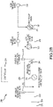
- the bleed air system 200 includes a low-pressure bleed tap 234 configured to bleed a low-pressure compressed air from a low-pressure source, such as, for example, the low-pressure compressor 120 described above with reference to FIG. 1B .
- a high-pressure bleed tap 236 is configured to bleed a high-pressure compressed air from a high-pressure source (relative to the low-pressure source), such as, for example, the high-pressure compressor 124 described above with reference to FIG. 1B .
- a low-pressure non-return valve 240 (or a low-pressure check valve) is positioned downstream of the low-pressure bleed tap 234 to prevent high-pressure air bled from the high-pressure compressor at the high-pressure bleed tap 236 from backflowing into the low-pressure compressor.
- a high-pressure shutoff valve 242 (or a high stage valve) is positioned downstream of the high-pressure bleed tap 236 and upstream of the low-pressure non-return valve 240. The high-pressure shutoff valve 242 facilitates, among other things, operation of the bleed air system 200 in a low-pressure mode, without a high-pressure input from the high-pressure bleed tap 236.
- the high-pressure bleed tap 236 is described as bleeding compressed air from the high-pressure compressor, the disclosure contemplates both the low-pressure bleed tap 234 and the high-pressure bleed tap 236 being configured to bleed air from the low-pressure compressor only.
- the low-pressure bleed tap 234 may be configured to bleed compressed air from a fourth or fifth stage of the low-pressure compressor, while the high-pressure bleed tap 236 may be configured to bleed compressed air from an eleventh or twelfth stage of the low-pressure compressor.
- the disclosure contemplates a similar arrangement using the high-pressure compressor only.
- the low-pressure bleed tap 234 may be configured to bleed compressed air from a fourth or fifth stage of the high-pressure compressor, while the high-pressure bleed tap 236 may be configured to bleed compressed air from an eleventh or twelfth stage of the high-pressure compressor.
- the common theme among the various embodiments is the high-pressure bleed tap 236 will be configured and positioned to bleed compressed air at a higher pressure than the pressure of the compressed air being bled at the low-pressure bleed tap 234.
- the bleed air system 200 includes a pressure regulating and shutoff valve 244.
- the pressure regulating and shutoff valve 244 is positioned downstream of both the low-pressure bleed tap 234 and the high-pressure bleed tap 236 and configured to control or modulate, and to shut off or turn on, the flow of compressed air within the bleed air system 200.
- the pressure regulating and shutoff valve 244 is also positioned upstream of the various pneumatic systems to which the compressed air is being delivered, such as, for example, a deicing or anti-icing system 252 or an environmental control system 254.
- the pressure regulating and shutoff valve 244 enables delivery of compressed air at different flow rates and at different pressures depending on the requirements of the various pneumatic systems to which the compressed air is being delivered.
- the pressure regulating and shutoff valve 244 comprises a self-regulating valve or an actively controlled valve (e.g., via a controller) based on the pressure of the compressed air upstream and downstream of the pressure regulating and shutoff valve 244 or any other engine, pneumatic system or environmental parameter pertinent to operation of the bleed air system 200 or the pneumatic system to which compressed air is being delivered.
- a pressure relief valve 246 Positioned upstream of the pressure regulating and shutoff valve 244 and downstream of both the low-pressure bleed tap 234 and the high-pressure bleed tap 236 is a pressure relief valve 246.
- the pressure relief valve 246 is configured to ensure the pressure of the compressed air in the bleed air system 200 or at the various pneumatic systems to which the compressed air is being delivered does not exceed a maximum design pressure.
- the pressure relief valve 246 comprises a self-regulating pressure relief valve (e.g., a self-activating valve) or an actively controlled pressure relief valve (e.g., via a controller).
- An upstream pressure transducer 248 is positioned upstream of the pressure regulating and shutoff valve 244 and downstream of both the low-pressure bleed tap 234 and the high-pressure bleed tap 236.
- the upstream pressure transducer 248 is configured to monitor the pressure of the compressed air in an upstream duct 256 (e.g., an upstream duct pressure), which connects each of the high-pressure shutoff valve 242, the low-pressure non-return valve 240 and the pressure regulating and shutoff valve 244.
- a downstream pressure transducer 250 is positioned downstream of the pressure regulating and shutoff valve 244 and upstream of the various pneumatic systems to which the compressed air is being delivered, such as, for example, the deicing or anti-icing system 252 or the environmental control system 254.
- the downstream pressure transducer 250 is configured to monitor the pressure of the compressed air in a downstream duct 258 (e.g., a downstream duct pressure), which connects each of the pressure regulating and shutoff valve 244 and the pneumatic system to which the compressed air is being delivered.
- a downstream duct 258 e.g., a downstream duct pressure
- the pressure of the compressed air in a downstream duct 258 may be considered a regulated compressed air that is regulated via the pressure regulating and shutoff valve 244.
- the high-pressure shutoff valve 242 comprises one or more bleed orifices 243 configured to better control pressurization of the upstream duct 256 (e.g., to reduce pressure fluctuations) and to prevent the components within the low-pressure non-return valve 240 from moving or flapping when the bleed air system 200 assumes a non-operational state while the aircraft or the compressor is in an operational state; such situation may occur, for example, when the aircraft is operating but the bleed air system 200 is not currently being used to supply compressed air to a pneumatic system.
- the one or more bleed orifices 243 enable a small quantity of high-pressure compressed air (e.g., a bypass flow) to pass through the high-pressure shutoff valve 242 when in the closed (or shutoff) position.
- a small quantity of high-pressure compressed air e.g., a bypass flow
- This enables the pressure of the compressed air in the upstream duct 256 to be lower than the pressure of the high-pressure compressed air at the high-pressure bleed tap 236 and higher than the low-pressure compressed air at the low-pressure bleed tap 234 during a non-operational state, thereby ensuring a sufficient pressure in the upstream duct 256 to prevent the low-pressure non-return valve 240 from opening (or moving or flapping) when the bleed air system 200 is non-operational, although the engine is operational.
- the bleed air system 200 also includes a controller 270 configured to control operation of the various valves described above.
- the controller 270 is connected to and receives input signals (or an input signal) from the cockpit concerning the various pneumatic systems to which the compressed air is to be or is being delivered or from the pneumatic systems themselves.
- the controller 270 is connected to and receives input signals (or an input signal) from the upstream pressure transducer 248 and the downstream pressure transducer 250 concerning the measured pressures, respectively, in the upstream duct 256 and the downstream duct 258.
- the controller 270 is also connected to and provides output signals (or an output signal) to the high-pressure shutoff valve 242, the low-pressure non-return valve 240 and the pressure regulating and shutoff valve 244, as well as to the low-pressure bleed tap 234 and the high-pressure bleed tap 236.
- the controller 270 in response, controls or monitors operation of the various valves, the low-pressure bleed tap 234 and the high-pressure bleed tap 236, and the various pneumatic systems to which the compressed air is being delivered.
- the controller 270 is also configured to provide output signals to the cockpit concerning the various pneumatic systems to which the compressed air is to be or is being delivered or to the pneumatic systems themselves.
- the controller 270 may also be configured to receive input signals from the high-pressure shutoff valve 242, the low-pressure non-return valve 240 and the pressure regulating and shutoff valve 244, as well as from the low-pressure bleed tap 234 and the high-pressure bleed tap 236.
- the various input signals received by the controller 270 concern operational commands or status of the various components of the bleed air system 200 or pressure measurements of the compressed air within the upstream duct 256 and the downstream duct 258 or at the low-pressure bleed tap 234 and the high-pressure bleed tap 236.
- the controller 270 is configured to detect a failure of one or more of the high-pressure shutoff valve 242, the pressure regulating and shutoff valve 244 and the pressure relief valve 246 based on an input signal received from the upstream pressure transducer 248.
- the controller 270 is also configured to regulate the pressure of the compressed air in the downstream duct 258 (e.g., via control signals sent to the pressure regulating and shutoff valve 244) to be supplied to, for example, the deicing or anti-icing system 252 or the environmental control system 254.
- system program instructions or controller instructions may be loaded onto a tangible, non-transitory, computer-readable medium (also referred to herein as a tangible, non-transitory, memory) having instructions stored thereon that, in response to the input signals described above, cause the controller 270 to perform various operations, including controlling the various valves comprised within the bleed air system 200.
- a tangible, non-transitory, computer-readable medium also referred to herein as a tangible, non-transitory, memory
- the pressure relief valve 246 is configured such that lower pressures (or a lower maximum pressure) in the upstream duct 256 may be maintained. This feature enables the low-pressure non-return valve 240 and the pressure regulating and shutoff valve 244 to be designed for lower operating pressures, which contributes to lower-weight components. Further, the various components comprising the ducting system - e.g., the upstream duct 256 - may be designed based on lower burst pressures (or lower maximum pressures), which also contributes to lower-weight components.
- the pressure relief valve 246 may be designed to regulate the pressure of the compressed air in the upstream duct 256 to a specific maximum pressure.
- the maximum pressure may be tuned to ensure the low-pressure non-return valve 240 is closed during non-operational conditions, preventing excessive mechanical cycles of the components within the low-pressure non-return valve 240.
- the pressure relief valve 246 e.g., the maximum pressure in the upstream duct 256, above which the pressure relief valve 246 opens
- reducing the maximum pressure of the pressure relief valve 246 e.g., the maximum pressure in the upstream duct 256, above which the pressure relief valve 246 opens
- reducing the maximum pressure of the pressure relief valve 246 e.g., the maximum pressure in the upstream duct 256, above which the pressure relief valve 246 opens
- the pressure relief valve 246 is configured to either dump (e.g., directly to the atmosphere) the compressed air within the upstream duct 256 (as depicted in FIG.2A ) or to route the compressed air out of the upstream duct 256 and to the downstream duct 258, via a bypass duct 260 (as depicted in FIG. 2B ), at which point the compressed air within the bleed air system 200 may be handled by other systems, such as, for example, the deicing or anti-icing system 252 or the environmental control system 254 or another system.
- the pressure relief valve 246 may be integrated into the high-pressure shutoff valve 242 or into the pressure regulating and shutoff valve 244.
- Other benefits of the bleed air system disclosed herein is the ability to optimize the consumption of bleed air during various of the flight regimes - e.g., takeoff, ascent, cruise, decent and landing - to maximize the specific fuel consumption.
- references to "one embodiment,” “an embodiment,” “various embodiments,” etc. indicate that the embodiment described may include a particular feature, structure, or characteristic, but every embodiment may not necessarily include the particular feature, structure, or characteristic. Moreover, such phrases are not necessarily referring to the same embodiment. Further, when a particular feature, structure, or characteristic is described in connection with an embodiment, it is submitted that it is within the knowledge of one skilled in the art to affect such feature, structure, or characteristic in connection with other embodiments whether or not explicitly described. After reading the description, it will be apparent to one skilled in the relevant art(s) how to implement the disclosure in alternative embodiments.
- system program instructions or controller instructions may be loaded onto a tangible, non-transitory, computer-readable medium (also referred to herein as a tangible, non-transitory, memory) having instructions stored thereon that, in response to execution by a controller, cause the controller to perform various operations.
- a tangible, non-transitory, computer-readable medium also referred to herein as a tangible, non-transitory, memory
- non-transitory is to be understood to remove only propagating transitory signals per se from the claim scope and does not relinquish rights to all standard computer-readable media that are not only propagating transitory signals per se.
- Numbers, percentages, or other values stated herein are intended to include that value, and also other values that are about or approximately equal to the stated value, as would be appreciated by one of ordinary skill in the art encompassed by various embodiments of the present disclosure.
- a stated value should therefore be interpreted broadly enough to encompass values that are at least close enough to the stated value to perform a desired function or achieve a desired result.
- the stated values include at least the variation to be expected in a suitable industrial process, and may include values that are within 10%, within 5%, within 1%, within 0.1%, or within 0.01% of a stated value.
- the terms “substantially,” “about” or “approximately” as used herein represent an amount close to the stated amount that still performs a desired function or achieves a desired result.
- the term “substantially,” “about” or “approximately” may refer to an amount that is within 10% of, within 5% of, within 1% of, within 0.1% of, and within 0.01% of a stated amount or value
Landscapes
- Engineering & Computer Science (AREA)
- Chemical & Material Sciences (AREA)
- Combustion & Propulsion (AREA)
- Mechanical Engineering (AREA)
- General Engineering & Computer Science (AREA)
- Aviation & Aerospace Engineering (AREA)
- Health & Medical Sciences (AREA)
- General Health & Medical Sciences (AREA)
- Pulmonology (AREA)
- Physics & Mathematics (AREA)
- Fluid Mechanics (AREA)
- Control Of Turbines (AREA)
Abstract
Description
- The present disclosure relates generally to aircraft pneumatic systems and, more particularly, to bleed air systems configured to bleed air from a compressor section of a gas turbine engine.
- Gas turbine engines of the turbofan, turbojet and turboprop types typically include a compressor section, a combustor section and a turbine section. In general, during operation, air is pressurized in the compressor section and is mixed with fuel and burned in the combustor section to generate hot combustion gases. Subsequent to combustion, the hot combustion gases flow through the turbine section, which extracts energy from the hot combustion gases to power the compressor section and other gas turbine engine loads, such as those required to rotate fan blades in a fan section of a turbofan engine, where the fan section drives air along a bypass flow path. The compressor section typically includes low-pressure and high-pressure compressors, and the turbine section includes low-pressure and high-pressure turbines.
- Many current aircraft, including commercial and business aircraft, use bleed air extracted from the main engines to supply conditioned air to various pneumatic systems, such as, for example, deicing or anti-icing systems or environmental control systems. This includes commercial passenger and cargo aircraft and business jet aircraft that are powered by turbojet, turbofan or turboprop engines. The air extracted from the main engines is supplied to and controlled by a bleed air system. The bleed air system is typically comprised of a series of valves, ducting and a pre-cooler, and extracts air from different ports of the compressor section of a gas turbine engine. This high-pressure and high temperature air may then be regulated or cooled before it is delivered downstream to the aircraft pneumatic systems.
- In one aspect a bleed air system for a pneumatic system of an aircraft is provided. The bleed air system includes: a low-pressure bleed tap configured to bleed a low-pressure compressed air from a low-pressure source; a high-pressure bleed tap configured to bleed a high-pressure compressed air from a high-pressure source; an upstream duct configured to receive one or both of the low-pressure compressed air and the high-pressure compressed air; a downstream duct configured to provide a regulated compressed air to the pneumatic system; a high-pressure shutoff valve positioned between the high-pressure bleed tap and the upstream duct; a low-pressure non-return valve positioned between the low-pressure bleed tap and the upstream duct; a pressure regulating and shutoff valve positioned between the upstream duct and the downstream duct, the pressure regulating and shutoff valve configured to generate the regulated compressed air; and a pressure relief valve positioned within the upstream duct.
- In various optional embodiments, the high-pressure shutoff valve includes one or more bleed orifices configured to allow a bypass flow to pass through the high-pressure shutoff valve when in a closed position during a non-operational state of the bleed air system and while the aircraft is in an operational state. In various optional embodiments, the one or more bleed orifices is configured to maintain an upstream duct pressure of a compressed air in the upstream duct to be lower than the pressure of the high-pressure compressed air at the high-pressure bleed tap and higher than the pressure of the low-pressure compressed air at the low-pressure bleed tap during the non-operational state. In various optional embodiments, the low-pressure non-return valve is constrained from movement via the upstream duct pressure of the compressed air in the upstream duct during the non-operational state.
- In various optional embodiments, the pressure relief valve is integrated into at least one of the high-pressure shutoff valve or the low-pressure non-return valve. In various optional embodiments, the pressure relief valve is configured to exhaust the compressed air to the atmosphere or to a location along the downstream duct, downstream of the pressure regulating and shutoff valve via a bypass duct. In various optional embodiments, the pressure relief valve is a self-regulating pressure relief valve. In various optional embodiments, the pressure relief valve is an actively controlled pressure relief valve.
- In various optional embodiments, a downstream pressure transducer is configured to monitor a downstream duct pressure of a compressed air in the downstream duct. In various optional embodiments, an upstream pressure transducer is configured to monitor an upstream duct pressure of a compressed air in the upstream duct. In various optional embodiments, a controller is operatively connected to the upstream pressure transducer and configured to detect a failure of one or more of the high-pressure shutoff valve, the pressure regulating and shutoff valve and the pressure relief valve based on an input signal received from the upstream pressure transducer and to regulate the downstream duct pressure of the compressed air in the downstream duct.
- In various optional embodiments, the low-pressure source is one of a low-pressure compressor or a high-pressure compressor. In various optional embodiments, the high-pressure source is one of the low-pressure compressor or the high-pressure compressor. In various optional embodiments, the pneumatic system is one of an anti-icing system or an environmental control system.
- In another aspect, a gas turbine engine is provided. The gas turbine engine includes: a low-pressure compressor; a high-pressure compressor; and a bleed air system, the bleed air system including a low-pressure bleed tap configured to bleed a low-pressure compressed air from the low-pressure compressor or the high-pressure compressor, a high-pressure bleed tap configured to bleed a high-pressure compressed air from the low-pressure compressor or the high-pressure compressor, an upstream duct configured to receive one or both of the low-pressure compressed air and the high-pressure compressed air, a downstream duct configured to provide a regulated compressed air to a pneumatic system, a high-pressure shutoff valve positioned between the high-pressure bleed tap and the upstream duct, a low-pressure non-return valve positioned between the low-pressure bleed tap and the upstream duct, a pressure regulating and shutoff valve positioned between the upstream duct and the downstream duct, the pressure regulating and shutoff valve configured to generate the regulated compressed air, and a pressure relief valve positioned within the upstream duct.
- In various optional embodiments, the high-pressure shutoff valve includes one or more bleed orifices configured to allow a bypass flow to pass through the high-pressure shutoff valve when in a closed position during a non-operational state of the bleed air system and while the gas turbine engine is in an operational state. In various optional embodiments, the one or more bleed orifices is configured to maintain an upstream duct pressure of a compressed air in the upstream duct to be lower than the pressure of the high-pressure compressed air at the high-pressure bleed tap and higher than the pressure of the low-pressure compressed air at the low-pressure bleed tap during the non-operational state. In various optional embodiments, the pressure relief valve is integrated into one at least one of the high-pressure shutoff valve and the low-pressure non-return valve.
- In various optional embodiments, a downstream pressure transducer is configured to monitor a downstream duct pressure in the downstream duct and an upstream pressure transducer configured to monitor the upstream duct pressure in the upstream duct. In various optional embodiments, a controller is operatively connected to the upstream pressure transducer and configured to detect a failure of one or more of the high-pressure shutoff valve, the pressure regulating and shutoff valve and the pressure relief valve based on an input signal received from the upstream pressure transducer and to regulate the downstream duct pressure of the compressed air in the downstream duct.
- The foregoing features and elements may be combined in any combination, without exclusivity, unless expressly indicated herein otherwise. These features and elements as well as the operation of the disclosed embodiments will become more apparent in light of the following description and accompanying drawings.
- The subject matter of the present disclosure is particularly pointed out and distinctly claimed in the concluding portion of the specification. A more complete understanding of the present disclosure, however, may best be obtained by referring to the following detailed description and claims in connection with the following drawings. While the drawings illustrate various embodiments employing the principles described herein, the drawings do not limit the scope of the claims.
-
FIG. 1A illustrates an aircraft having fuselage mounted gas turbine engines, in accordance with various embodiments; -
FIG. 1B illustrates a schematic cross-sectional view of a gas turbine engine, in accordance with various embodiments; -
FIG. 2A illustrates a schematic view of a bleed air system, in accordance with various embodiments; and -
FIG. 2B illustrates a schematic view of a bleed air system, in accordance with various embodiments. - The following detailed description of various embodiments herein makes reference to the accompanying drawings, which show various embodiments by way of illustration. While these various embodiments are described in sufficient detail to enable those skilled in the art to practice the disclosure, it should be understood that other embodiments may be realized and that changes may be made without departing from the scope of the disclosure. Thus, the detailed description herein is presented for purposes of illustration only and not of limitation. Furthermore, any reference to singular includes plural embodiments, and any reference to more than one component or step may include a singular embodiment or step. Also, any reference to attached, fixed, connected, or the like may include permanent, removable, temporary, partial, full or any other possible attachment option. Additionally, any reference to without contact (or similar phrases) may also include reduced contact or minimal contact. It should also be understood that unless specifically stated otherwise, references to "a," "an" or "the" may include one or more than one and that reference to an item in the singular may also include the item in the plural. Further, all ranges may include upper and lower values and all ranges and ratio limits disclosed herein may be combined.
- Referring now to the drawings,
FIG. 1A schematically illustrates anaircraft 10, in accordance with various embodiments. Theaircraft 10 generally includes afuselage 12 extending the length of theaircraft 10. Awing 14 is attached to and extends from respective sides of thefuselage 12. Agas turbine engine 16 is likewise attached to and extends from respective sides of thefuselage 12. In various embodiments, thegas turbine engine 16 is attached to thefuselage 12 via apylon 18. Further, in various embodiments, thegas turbine engine 16 includes afan cowl assembly 20, aninlet section 22 and a thrust reverser 24. In various embodiments, thegas turbine engine 16 includes an anti-icing system 26 (or a deicing system) for the nacelle inlet and thewing 14 includes an anti-icing system 28 (or a deicing system) for the leading edge. Note that whileFIG. 1A depicts thegas turbine engine 16 as being attached to the side of thefuselage 12, the disclosure contemplates, without loss of generality, thegas turbine engine 16 being attached to an underside of thewing 14. The concepts described by the disclosure are the same regardless of where thegas turbine engine 16 is located on or how thegas turbine engine 16 is otherwise attached to theaircraft 10. - With continued reference to the drawings,
FIG. 1B schematically illustrates agas turbine engine 100 of the turbofan variety, similar to thegas turbine engine 16 described above with reference toFIG. 1A . Thegas turbine engine 100 generally includes afan section 102 and acore engine section 104, which includes acompressor section 106, acombustor section 108 and a turbine section 110. Thefan section 102 drives air along a bypass flow path B in a bypass duct 112 defined within a radially inner surface 114 of anacelle 116 and anouter casing 117 of thecore engine section 104, while thecompressor section 106 drives air along a core flow path C of thecore engine section 104 for compression and communication into thecombustor section 108 and then expansion through the turbine section 110. - The
core engine section 104 may generally include a low-speed spool and a high-speed spool mounted for rotation about a central longitudinal axis A. The low-speed spool generally includes an inner shaft that interconnects afan 118 within thefan section 102, a low-pressure compressor 120 within thecompressor section 106 and a low-pressure turbine 122 within the turbine section 110. The inner shaft may be connected to thefan 118 through a speed change mechanism or gear box to drive thefan 118 at a lower rotational speed than the rotational speed of the low-speed spool. The high-speed spool generally includes an outer shaft that interconnects a high-pressure compressor 124 within thecompressor section 106 and a high-pressure turbine 126 within the turbine section 110. Acombustor 128 is arranged in thecombustor section 108 between the high-pressure compressor 124 and the high-pressure turbine 126. The air passing through the bypass flow path B mixes with the combustion gases exiting the core flow path C in amixing section 130 positioned downstream of thecore engine section 104 prior to discharge as amixed exhaust stream 132, which provides the thrust achieved by thegas turbine engine 100. In various embodiments, as described further below, a low-pressure bleed tap 134 is positioned proximate a stage of the low-pressure compressor 120 and a high-pressure bleed tap 136 is positioned proximate stage of the high-pressure compressor 124. The low-pressure bleed tap 134 and the high-pressure bleed tap 136 are configured to bleed compressed air, respectively, from the low-pressure compressor 120 and the high-pressure compressor 124 to supply compressed air to various pneumatic systems throughout the aircraft, such as, for example, deicing or anti-icing systems or environmental control systems. - Referring now to
FIGS. 2A and2B , schematic illustrations of ableed air system 200 for an aircraft are provided, in accordance with various embodiments. Thebleed air system 200 includes a low-pressure bleed tap 234 configured to bleed a low-pressure compressed air from a low-pressure source, such as, for example, the low-pressure compressor 120 described above with reference toFIG. 1B . Similarly, a high-pressure bleed tap 236 is configured to bleed a high-pressure compressed air from a high-pressure source (relative to the low-pressure source), such as, for example, the high-pressure compressor 124 described above with reference toFIG. 1B . A low-pressure non-return valve 240 (or a low-pressure check valve) is positioned downstream of the low-pressure bleed tap 234 to prevent high-pressure air bled from the high-pressure compressor at the high-pressure bleed tap 236 from backflowing into the low-pressure compressor. A high-pressure shutoff valve 242 (or a high stage valve) is positioned downstream of the high-pressure bleed tap 236 and upstream of the low-pressurenon-return valve 240. The high-pressure shutoff valve 242 facilitates, among other things, operation of thebleed air system 200 in a low-pressure mode, without a high-pressure input from the high-pressure bleed tap 236. - Note that while the high-
pressure bleed tap 236 is described as bleeding compressed air from the high-pressure compressor, the disclosure contemplates both the low-pressure bleed tap 234 and the high-pressure bleed tap 236 being configured to bleed air from the low-pressure compressor only. For example, in various embodiments, the low-pressure bleed tap 234 may be configured to bleed compressed air from a fourth or fifth stage of the low-pressure compressor, while the high-pressure bleed tap 236 may be configured to bleed compressed air from an eleventh or twelfth stage of the low-pressure compressor. The disclosure contemplates a similar arrangement using the high-pressure compressor only. For example, in various embodiments, the low-pressure bleed tap 234 may be configured to bleed compressed air from a fourth or fifth stage of the high-pressure compressor, while the high-pressure bleed tap 236 may be configured to bleed compressed air from an eleventh or twelfth stage of the high-pressure compressor. The common theme among the various embodiments is the high-pressure bleed tap 236 will be configured and positioned to bleed compressed air at a higher pressure than the pressure of the compressed air being bled at the low-pressure bleed tap 234. - Still referring to
FIGS. 2A and2B , thebleed air system 200 includes a pressure regulating andshutoff valve 244. The pressure regulating andshutoff valve 244 is positioned downstream of both the low-pressure bleed tap 234 and the high-pressure bleed tap 236 and configured to control or modulate, and to shut off or turn on, the flow of compressed air within thebleed air system 200. The pressure regulating andshutoff valve 244 is also positioned upstream of the various pneumatic systems to which the compressed air is being delivered, such as, for example, a deicing oranti-icing system 252 or anenvironmental control system 254. In various embodiments, the pressure regulating andshutoff valve 244 enables delivery of compressed air at different flow rates and at different pressures depending on the requirements of the various pneumatic systems to which the compressed air is being delivered. In various embodiments, the pressure regulating andshutoff valve 244 comprises a self-regulating valve or an actively controlled valve (e.g., via a controller) based on the pressure of the compressed air upstream and downstream of the pressure regulating andshutoff valve 244 or any other engine, pneumatic system or environmental parameter pertinent to operation of thebleed air system 200 or the pneumatic system to which compressed air is being delivered. Positioned upstream of the pressure regulating andshutoff valve 244 and downstream of both the low-pressure bleed tap 234 and the high-pressure bleed tap 236 is apressure relief valve 246. In various embodiments, thepressure relief valve 246 is configured to ensure the pressure of the compressed air in thebleed air system 200 or at the various pneumatic systems to which the compressed air is being delivered does not exceed a maximum design pressure. In various embodiments, thepressure relief valve 246 comprises a self-regulating pressure relief valve (e.g., a self-activating valve) or an actively controlled pressure relief valve (e.g., via a controller). - An
upstream pressure transducer 248 is positioned upstream of the pressure regulating andshutoff valve 244 and downstream of both the low-pressure bleed tap 234 and the high-pressure bleed tap 236. Theupstream pressure transducer 248 is configured to monitor the pressure of the compressed air in an upstream duct 256 (e.g., an upstream duct pressure), which connects each of the high-pressure shutoff valve 242, the low-pressurenon-return valve 240 and the pressure regulating andshutoff valve 244. Adownstream pressure transducer 250 is positioned downstream of the pressure regulating andshutoff valve 244 and upstream of the various pneumatic systems to which the compressed air is being delivered, such as, for example, the deicing oranti-icing system 252 or theenvironmental control system 254. Thedownstream pressure transducer 250 is configured to monitor the pressure of the compressed air in a downstream duct 258 (e.g., a downstream duct pressure), which connects each of the pressure regulating andshutoff valve 244 and the pneumatic system to which the compressed air is being delivered. Without loss of generality, the pressure of the compressed air in adownstream duct 258 may be considered a regulated compressed air that is regulated via the pressure regulating andshutoff valve 244. In various embodiments, the high-pressure shutoff valve 242 comprises one ormore bleed orifices 243 configured to better control pressurization of the upstream duct 256 (e.g., to reduce pressure fluctuations) and to prevent the components within the low-pressurenon-return valve 240 from moving or flapping when thebleed air system 200 assumes a non-operational state while the aircraft or the compressor is in an operational state; such situation may occur, for example, when the aircraft is operating but thebleed air system 200 is not currently being used to supply compressed air to a pneumatic system. In various embodiments, for example, the one ormore bleed orifices 243 enable a small quantity of high-pressure compressed air (e.g., a bypass flow) to pass through the high-pressure shutoff valve 242 when in the closed (or shutoff) position. This enables the pressure of the compressed air in theupstream duct 256 to be lower than the pressure of the high-pressure compressed air at the high-pressure bleed tap 236 and higher than the low-pressure compressed air at the low-pressure bleed tap 234 during a non-operational state, thereby ensuring a sufficient pressure in theupstream duct 256 to prevent the low-pressurenon-return valve 240 from opening (or moving or flapping) when thebleed air system 200 is non-operational, although the engine is operational. - The
bleed air system 200 also includes acontroller 270 configured to control operation of the various valves described above. For example, thecontroller 270 is connected to and receives input signals (or an input signal) from the cockpit concerning the various pneumatic systems to which the compressed air is to be or is being delivered or from the pneumatic systems themselves. Similarly, thecontroller 270 is connected to and receives input signals (or an input signal) from theupstream pressure transducer 248 and thedownstream pressure transducer 250 concerning the measured pressures, respectively, in theupstream duct 256 and thedownstream duct 258. In various embodiments, thecontroller 270 is also connected to and provides output signals (or an output signal) to the high-pressure shutoff valve 242, the low-pressurenon-return valve 240 and the pressure regulating andshutoff valve 244, as well as to the low-pressure bleed tap 234 and the high-pressure bleed tap 236. Depending on the input signals received by thecontroller 270, thecontroller 270, in response, controls or monitors operation of the various valves, the low-pressure bleed tap 234 and the high-pressure bleed tap 236, and the various pneumatic systems to which the compressed air is being delivered. In various embodiments, thecontroller 270 is also configured to provide output signals to the cockpit concerning the various pneumatic systems to which the compressed air is to be or is being delivered or to the pneumatic systems themselves. Similarly, thecontroller 270 may also be configured to receive input signals from the high-pressure shutoff valve 242, the low-pressurenon-return valve 240 and the pressure regulating andshutoff valve 244, as well as from the low-pressure bleed tap 234 and the high-pressure bleed tap 236. Typically, the various input signals received by thecontroller 270 concern operational commands or status of the various components of thebleed air system 200 or pressure measurements of the compressed air within theupstream duct 256 and thedownstream duct 258 or at the low-pressure bleed tap 234 and the high-pressure bleed tap 236. In various embodiments, thecontroller 270 is configured to detect a failure of one or more of the high-pressure shutoff valve 242, the pressure regulating andshutoff valve 244 and thepressure relief valve 246 based on an input signal received from theupstream pressure transducer 248. Thecontroller 270 is also configured to regulate the pressure of the compressed air in the downstream duct 258 (e.g., via control signals sent to the pressure regulating and shutoff valve 244) to be supplied to, for example, the deicing oranti-icing system 252 or theenvironmental control system 254. In various embodiments, system program instructions or controller instructions may be loaded onto a tangible, non-transitory, computer-readable medium (also referred to herein as a tangible, non-transitory, memory) having instructions stored thereon that, in response to the input signals described above, cause thecontroller 270 to perform various operations, including controlling the various valves comprised within thebleed air system 200. - The above disclosure provides a bleed air system (e.g., the bleed air system 200) that exhibits less complexity and less overall system weight than do current bleed air systems. In various embodiments, for example, the
pressure relief valve 246 is configured such that lower pressures (or a lower maximum pressure) in theupstream duct 256 may be maintained. This feature enables the low-pressurenon-return valve 240 and the pressure regulating andshutoff valve 244 to be designed for lower operating pressures, which contributes to lower-weight components. Further, the various components comprising the ducting system - e.g., the upstream duct 256 - may be designed based on lower burst pressures (or lower maximum pressures), which also contributes to lower-weight components. Consistent with the foregoing, thepressure relief valve 246 may be designed to regulate the pressure of the compressed air in theupstream duct 256 to a specific maximum pressure. In various embodiments, the maximum pressure may be tuned to ensure the low-pressurenon-return valve 240 is closed during non-operational conditions, preventing excessive mechanical cycles of the components within the low-pressurenon-return valve 240. Further, reducing the maximum pressure of the pressure relief valve 246 (e.g., the maximum pressure in theupstream duct 256, above which thepressure relief valve 246 opens) to a pressure below the maximum pressure of the compressed air bled from the high-pressure bleed tap 236 enables the low-pressurenon-return valve 240 and the pressure regulating andshutoff valve 244 to be designed using lower-weight components. In the event thepressure relief valve 246 is activated (e.g., due to an over-pressure in the upstream duct 256), thepressure relief valve 246 is configured to either dump (e.g., directly to the atmosphere) the compressed air within the upstream duct 256 (as depicted inFIG.2A ) or to route the compressed air out of theupstream duct 256 and to thedownstream duct 258, via a bypass duct 260 (as depicted inFIG. 2B ), at which point the compressed air within thebleed air system 200 may be handled by other systems, such as, for example, the deicing oranti-icing system 252 or theenvironmental control system 254 or another system. Further, in various embodiments, thepressure relief valve 246 may be integrated into the high-pressure shutoff valve 242 or into the pressure regulating andshutoff valve 244. Other benefits of the bleed air system disclosed herein is the ability to optimize the consumption of bleed air during various of the flight regimes - e.g., takeoff, ascent, cruise, decent and landing - to maximize the specific fuel consumption. - Benefits, other advantages, and solutions to problems have been described herein with regard to specific embodiments. Furthermore, the connecting lines shown in the various figures contained herein are intended to represent exemplary functional relationships and/or physical couplings between the various elements. It should be noted that many alternative or additional functional relationships or physical connections may be present in a practical system. However, the benefits, advantages, solutions to problems, and any elements that may cause any benefit, advantage, or solution to occur or become more pronounced are not to be construed as critical, required, or essential features or elements of the disclosure. The scope of the disclosure is accordingly to be limited by nothing other than the appended claims, in which reference to an element in the singular is not intended to mean "one and only one" unless explicitly so stated, but rather "one or more." Moreover, where a phrase similar to "at least one of A, B, or C" is used in the claims, it is intended that the phrase be interpreted to mean that A alone may be present in an embodiment, B alone may be present in an embodiment, C alone may be present in an embodiment, or that any combination of the elements A, B and C may be present in a single embodiment; for example, A and B, A and C, B and C, or A and B and C. Different cross-hatching is used throughout the figures to denote different parts but not necessarily to denote the same or different materials.
- Systems, methods and apparatus are provided herein. In the detailed description herein, references to "one embodiment," "an embodiment," "various embodiments," etc., indicate that the embodiment described may include a particular feature, structure, or characteristic, but every embodiment may not necessarily include the particular feature, structure, or characteristic. Moreover, such phrases are not necessarily referring to the same embodiment. Further, when a particular feature, structure, or characteristic is described in connection with an embodiment, it is submitted that it is within the knowledge of one skilled in the art to affect such feature, structure, or characteristic in connection with other embodiments whether or not explicitly described. After reading the description, it will be apparent to one skilled in the relevant art(s) how to implement the disclosure in alternative embodiments.
- In various embodiments, system program instructions or controller instructions may be loaded onto a tangible, non-transitory, computer-readable medium (also referred to herein as a tangible, non-transitory, memory) having instructions stored thereon that, in response to execution by a controller, cause the controller to perform various operations. The term "non-transitory" is to be understood to remove only propagating transitory signals per se from the claim scope and does not relinquish rights to all standard computer-readable media that are not only propagating transitory signals per se.
- Furthermore, no element, component, or method step in the present disclosure is intended to be dedicated to the public regardless of whether the element, component, or method step is explicitly recited in the claims. As used herein, the terms "comprises," "comprising," or any other variation thereof, are intended to cover a non-exclusive inclusion, such that a process, method, article, or apparatus that comprises a list of elements does not include only those elements but may include other elements not expressly listed or inherent to such process, method, article, or apparatus.
- Numbers, percentages, or other values stated herein are intended to include that value, and also other values that are about or approximately equal to the stated value, as would be appreciated by one of ordinary skill in the art encompassed by various embodiments of the present disclosure. A stated value should therefore be interpreted broadly enough to encompass values that are at least close enough to the stated value to perform a desired function or achieve a desired result. The stated values include at least the variation to be expected in a suitable industrial process, and may include values that are within 10%, within 5%, within 1%, within 0.1%, or within 0.01% of a stated value. Additionally, the terms "substantially," "about" or "approximately" as used herein represent an amount close to the stated amount that still performs a desired function or achieves a desired result. For example, the term "substantially," "about" or "approximately" may refer to an amount that is within 10% of, within 5% of, within 1% of, within 0.1% of, and within 0.01% of a stated amount or value.
- Finally, any of the above described concepts can be used alone or in combination with any or all of the other above described concepts. Although various embodiments have been disclosed and described, one of ordinary skill in this art would recognize that certain modifications would come within the scope of this disclosure. Accordingly, the description is not intended to be exhaustive or to limit the principles described or illustrated herein to any precise form. Many modifications and variations are possible in light of the above teaching.
Claims (15)
- A bleed air system for a pneumatic system of an aircraft, comprising:a low-pressure bleed tap (234) configured to bleed a low-pressure compressed air from a low-pressure source (120);a high-pressure bleed tap (236) configured to bleed a high-pressure compressed air from a high-pressure source (124);an upstream duct (256) configured to receive one or both of the low-pressure compressed air and the high-pressure compressed air;a downstream duct (258) configured to provide a regulated compressed air to the pneumatic system;a high-pressure shutoff valve (242) positioned between the high-pressure bleed tap (236) and the upstream duct (256);a low-pressure non-return valve (240) positioned between the low-pressure bleed tap (234) and the upstream duct (256);a pressure regulating and shutoff valve (244) positioned between the upstream duct (256) and the downstream duct (258), the pressure regulating and shutoff valve (244) configured to generate the regulated compressed air; anda pressure relief valve (246) positioned within the upstream duct (256).
- The bleed air system of claim 1, wherein the high-pressure shutoff valve (242) includes one or more bleed orifices (243) configured to allow a bypass flow to pass through the high-pressure shutoff valve (242) when in a closed position during a non-operational state of the bleed air system and while an aircraft is in an operational state.
- The bleed air system of claim 2, wherein the one or more bleed orifices (243) is configured to maintain an upstream duct pressure of compressed air in the upstream duct (256) to be lower than the pressure of the high-pressure compressed air at the high-pressure bleed tap (236) and higher than the pressure of the low-pressure compressed air at the low-pressure bleed tap (234) during the non-operational state.
- The bleed air system of claim 3, wherein the low-pressure non-return valve (240) is constrained from movement via the upstream duct pressure of compressed air in the upstream duct (256) during the non-operational state.
- The bleed air system of any preceding claim, wherein:the pressure relief valve (246) is integrated into at least one of the high-pressure shutoff valve (242) or the low-pressure non-return valve (240); and/orthe pressure relief valve (246) is configured to exhaust compressed air to the atmosphere or to a location along the downstream duct (258), downstream of the pressure regulating and shutoff valve (244) via a bypass duct (260).
- The bleed air system of any preceding claim, wherein:the pressure relief valve (246) is a self-regulating pressure relief valve; orthe pressure relief valve (246) is an actively controlled pressure relief valve.
- The bleed air system of any preceding claim, further comprising a downstream pressure transducer (250) configured to monitor a downstream duct pressure of compressed air in the downstream duct (258).
- The bleed air system of any preceding claim, further comprising an upstream pressure transducer (248) configured to monitor an or the upstream duct pressure of compressed air in the upstream duct (256).
- The bleed air system of claim 8, further comprising a controller (270), the controller (270) being operatively connected to the upstream pressure transducer (248) and configured to detect a failure of one or more of the high-pressure shutoff valve (242), the pressure regulating and shutoff valve (244) and the pressure relief valve (246) based on an input signal received from the upstream pressure transducer (248) and to regulate the downstream duct pressure of compressed air in the downstream duct (258).
- The bleed air system of any preceding claim, wherein the low-pressure source is one of a low-pressure compressor (120) or a high-pressure compressor (124).
- The bleed air system of any preceding claim, wherein the high-pressure source is one of a or the low-pressure compressor (120) or a or the high-pressure compressor (124).
- The bleed air system of any preceding claim, wherein the pneumatic system is one of an anti-icing system or an environmental control system.
- A gas turbine engine, comprising:a low-pressure compressor;a high-pressure compressor; andthe bleed air system of any preceding claim, wherein the low-pressure source is one of a low-pressure compressor (120) or a high-pressure compressor (124), and the high-pressure source is one of the low-pressure compressor (120) or the high-pressure compressor.
- The gas turbine engine of claim 13, wherein the high-pressure shutoff valve (242) includes one or more bleed orifices (243) configured to allow a bypass flow to pass through the high-pressure shutoff valve (242) when in a closed position during a non-operational state of the bleed air system and while the gas turbine engine is in an operational state.
- The gas turbine engine of claim 14, wherein the one or more bleed orifices (243) is configured to maintain an upstream duct pressure of compressed air in the upstream duct (256) to be lower than the pressure of the high-pressure compressed air at the high-pressure bleed tap (236) and higher than the pressure of the low-pressure compressed air at the low-pressure bleed tap (234) during the non-operational state.
Applications Claiming Priority (1)
| Application Number | Priority Date | Filing Date | Title |
|---|---|---|---|
| US17/341,282 US11448126B1 (en) | 2021-06-07 | 2021-06-07 | Dual-pressure source aircraft pneumatic system with pressure relief |
Publications (1)
| Publication Number | Publication Date |
|---|---|
| EP4102042A1 true EP4102042A1 (en) | 2022-12-14 |
Family
ID=81975234
Family Applications (1)
| Application Number | Title | Priority Date | Filing Date |
|---|---|---|---|
| EP22177474.8A Pending EP4102042A1 (en) | 2021-06-07 | 2022-06-07 | Dual-pressure source aircraft pneumatic system with pressure relief |
Country Status (2)
| Country | Link |
|---|---|
| US (1) | US11448126B1 (en) |
| EP (1) | EP4102042A1 (en) |
Cited By (1)
| Publication number | Priority date | Publication date | Assignee | Title |
|---|---|---|---|---|
| EP4411123A1 (en) * | 2023-01-31 | 2024-08-07 | Rohr, Inc. | Aircraft anti-icing system |
Families Citing this family (1)
| Publication number | Priority date | Publication date | Assignee | Title |
|---|---|---|---|---|
| US11976592B1 (en) | 2023-01-03 | 2024-05-07 | Rohr, Inc. | Anti-icing system and method for an aircraft propulsion system |
Citations (4)
| Publication number | Priority date | Publication date | Assignee | Title |
|---|---|---|---|---|
| EP2829706A1 (en) * | 2013-07-25 | 2015-01-28 | The Boeing Company | Bleed air systems for use with aircrafts and related methods |
| US20160237915A1 (en) * | 2015-02-16 | 2016-08-18 | Dukes Aerospace | Redundant Valve System |
| US20170101937A1 (en) * | 2015-10-13 | 2017-04-13 | Honeywell International Inc. | Flow limiting duct vent valves and gas turbine engine bleed air systems including the same |
| EP3543134A1 (en) * | 2018-03-21 | 2019-09-25 | Hamilton Sundstrand Corporation | Environmental control system including shared air source with balanced airflow output |
Family Cites Families (6)
| Publication number | Priority date | Publication date | Assignee | Title |
|---|---|---|---|---|
| DE10321154A1 (en) * | 2003-05-12 | 2004-12-02 | Robert Bosch Gmbh | Valve |
| US20120045317A1 (en) | 2010-08-23 | 2012-02-23 | Honeywell International Inc. | Fuel actuated bleed air system |
| US8955794B2 (en) | 2012-01-24 | 2015-02-17 | The Boeing Company | Bleed air systems for use with aircrafts and related methods |
| US10060358B2 (en) * | 2016-04-19 | 2018-08-28 | General Electric Company | Compressor bleed valve health assessment systems and methods |
| EP4194676A1 (en) * | 2017-05-25 | 2023-06-14 | Ge Avio S.r.l. | Controlling a compressor of a turbine engine |
| US11053949B2 (en) * | 2018-08-03 | 2021-07-06 | Hamilton Sundstrand Corporation | Passively controlled inline bleed valves |
-
2021
- 2021-06-07 US US17/341,282 patent/US11448126B1/en active Active
-
2022
- 2022-06-07 EP EP22177474.8A patent/EP4102042A1/en active Pending
Patent Citations (4)
| Publication number | Priority date | Publication date | Assignee | Title |
|---|---|---|---|---|
| EP2829706A1 (en) * | 2013-07-25 | 2015-01-28 | The Boeing Company | Bleed air systems for use with aircrafts and related methods |
| US20160237915A1 (en) * | 2015-02-16 | 2016-08-18 | Dukes Aerospace | Redundant Valve System |
| US20170101937A1 (en) * | 2015-10-13 | 2017-04-13 | Honeywell International Inc. | Flow limiting duct vent valves and gas turbine engine bleed air systems including the same |
| EP3543134A1 (en) * | 2018-03-21 | 2019-09-25 | Hamilton Sundstrand Corporation | Environmental control system including shared air source with balanced airflow output |
Cited By (1)
| Publication number | Priority date | Publication date | Assignee | Title |
|---|---|---|---|---|
| EP4411123A1 (en) * | 2023-01-31 | 2024-08-07 | Rohr, Inc. | Aircraft anti-icing system |
Also Published As
| Publication number | Publication date |
|---|---|
| US11448126B1 (en) | 2022-09-20 |
Similar Documents
| Publication | Publication Date | Title |
|---|---|---|
| US6283410B1 (en) | Secondary power integrated cabin energy system for a pressurized aircraft | |
| US11873766B2 (en) | Differential geared amplification of auxiliary power unit | |
| US20260117709A1 (en) | Controlling a compressor of a turbine engine | |
| US8291715B2 (en) | Bi-modal turbine assembly and starter / drive turbine system employing the same | |
| US10858112B2 (en) | Supply of air to an air-conditioning circuit of an aircraft cabin from its turboprop engine | |
| US8356486B2 (en) | APU bleed valve with integral anti-surge port | |
| EP3321490B1 (en) | Turbo-generator based bleed air system | |
| EP4102042A1 (en) | Dual-pressure source aircraft pneumatic system with pressure relief | |
| US20220213838A1 (en) | Air system switching system to allow aero-engines to operate in standby mode | |
| EP3744636B1 (en) | Air system of multi-engine aircraft | |
| EP3770404B1 (en) | Fuel delivery system and method | |
| EP3770406B1 (en) | Fuel delivery system and method | |
| EP3770405A1 (en) | Fuel delivery system and method | |
| US20260043355A1 (en) | System to Selectively Transfer Power of a Turbine Engine | |
| CA3129994A1 (en) | Aircraft and method of operating same |
Legal Events
| Date | Code | Title | Description |
|---|---|---|---|
| PUAI | Public reference made under article 153(3) epc to a published international application that has entered the european phase |
Free format text: ORIGINAL CODE: 0009012 |
|
| STAA | Information on the status of an ep patent application or granted ep patent |
Free format text: STATUS: THE APPLICATION HAS BEEN PUBLISHED |
|
| AK | Designated contracting states |
Kind code of ref document: A1 Designated state(s): AL AT BE BG CH CY CZ DE DK EE ES FI FR GB GR HR HU IE IS IT LI LT LU LV MC MK MT NL NO PL PT RO RS SE SI SK SM TR |
|
| STAA | Information on the status of an ep patent application or granted ep patent |
Free format text: STATUS: REQUEST FOR EXAMINATION WAS MADE |
|
| 17P | Request for examination filed |
Effective date: 20230612 |
|
| RBV | Designated contracting states (corrected) |
Designated state(s): AL AT BE BG CH CY CZ DE DK EE ES FI FR GB GR HR HU IE IS IT LI LT LU LV MC MK MT NL NO PL PT RO RS SE SI SK SM TR |
|
| STAA | Information on the status of an ep patent application or granted ep patent |
Free format text: STATUS: EXAMINATION IS IN PROGRESS |
|
| 17Q | First examination report despatched |
Effective date: 20240904 |