EP4102041A1 - Turbonfan engine and method of operating same - Google Patents
Turbonfan engine and method of operating same Download PDFInfo
- Publication number
- EP4102041A1 EP4102041A1 EP22178506.6A EP22178506A EP4102041A1 EP 4102041 A1 EP4102041 A1 EP 4102041A1 EP 22178506 A EP22178506 A EP 22178506A EP 4102041 A1 EP4102041 A1 EP 4102041A1
- Authority
- EP
- European Patent Office
- Prior art keywords
- auxiliary
- flow
- proximal end
- duct
- passage
- Prior art date
- Legal status (The legal status is an assumption and is not a legal conclusion. Google has not performed a legal analysis and makes no representation as to the accuracy of the status listed.)
- Granted
Links
Images





Classifications
-
- F—MECHANICAL ENGINEERING; LIGHTING; HEATING; WEAPONS; BLASTING
- F02—COMBUSTION ENGINES; HOT-GAS OR COMBUSTION-PRODUCT ENGINE PLANTS
- F02C—GAS-TURBINE PLANTS; AIR INTAKES FOR JET-PROPULSION PLANTS; CONTROLLING FUEL SUPPLY IN AIR-BREATHING JET-PROPULSION PLANTS
- F02C6/00—Plural gas-turbine plants; Combinations of gas-turbine plants with other apparatus; Adaptations of gas-turbine plants for special use
- F02C6/04—Gas-turbine plants providing heated or pressurised working fluid for other apparatus, e.g. without mechanical power output
- F02C6/06—Gas-turbine plants providing heated or pressurised working fluid for other apparatus, e.g. without mechanical power output providing compressed gas
-
- F—MECHANICAL ENGINEERING; LIGHTING; HEATING; WEAPONS; BLASTING
- F02—COMBUSTION ENGINES; HOT-GAS OR COMBUSTION-PRODUCT ENGINE PLANTS
- F02C—GAS-TURBINE PLANTS; AIR INTAKES FOR JET-PROPULSION PLANTS; CONTROLLING FUEL SUPPLY IN AIR-BREATHING JET-PROPULSION PLANTS
- F02C6/00—Plural gas-turbine plants; Combinations of gas-turbine plants with other apparatus; Adaptations of gas-turbine plants for special use
- F02C6/04—Gas-turbine plants providing heated or pressurised working fluid for other apparatus, e.g. without mechanical power output
- F02C6/06—Gas-turbine plants providing heated or pressurised working fluid for other apparatus, e.g. without mechanical power output providing compressed gas
- F02C6/08—Gas-turbine plants providing heated or pressurised working fluid for other apparatus, e.g. without mechanical power output providing compressed gas the gas being bled from the gas-turbine compressor
-
- B—PERFORMING OPERATIONS; TRANSPORTING
- B64—AIRCRAFT; AVIATION; COSMONAUTICS
- B64D—EQUIPMENT FOR FITTING IN OR TO AIRCRAFT; FLIGHT SUITS; PARACHUTES; ARRANGEMENT OR MOUNTING OF POWER PLANTS OR PROPULSION TRANSMISSIONS IN AIRCRAFT
- B64D13/00—Arrangements or adaptations of air-treatment apparatus for aircraft crew or passengers, or freight space
- B64D13/06—Arrangements or adaptations of air-treatment apparatus for aircraft crew or passengers, or freight space the air being conditioned
-
- F—MECHANICAL ENGINEERING; LIGHTING; HEATING; WEAPONS; BLASTING
- F02—COMBUSTION ENGINES; HOT-GAS OR COMBUSTION-PRODUCT ENGINE PLANTS
- F02C—GAS-TURBINE PLANTS; AIR INTAKES FOR JET-PROPULSION PLANTS; CONTROLLING FUEL SUPPLY IN AIR-BREATHING JET-PROPULSION PLANTS
- F02C9/00—Controlling gas-turbine plants; Controlling fuel supply in air- breathing jet-propulsion plants
- F02C9/16—Control of working fluid flow
- F02C9/18—Control of working fluid flow by bleeding, bypassing or acting on variable working fluid interconnections between turbines or compressors or their stages
-
- F—MECHANICAL ENGINEERING; LIGHTING; HEATING; WEAPONS; BLASTING
- F02—COMBUSTION ENGINES; HOT-GAS OR COMBUSTION-PRODUCT ENGINE PLANTS
- F02K—JET-PROPULSION PLANTS
- F02K1/00—Plants characterised by the form or arrangement of the jet pipe or nozzle; Jet pipes or nozzles peculiar thereto
- F02K1/78—Other construction of jet pipes
- F02K1/82—Jet pipe walls, e.g. liners
- F02K1/827—Sound absorbing structures or liners
-
- F—MECHANICAL ENGINEERING; LIGHTING; HEATING; WEAPONS; BLASTING
- F02—COMBUSTION ENGINES; HOT-GAS OR COMBUSTION-PRODUCT ENGINE PLANTS
- F02K—JET-PROPULSION PLANTS
- F02K3/00—Plants including a gas turbine driving a compressor or a ducted fan
- F02K3/02—Plants including a gas turbine driving a compressor or a ducted fan in which part of the working fluid by-passes the turbine and combustion chamber
- F02K3/04—Plants including a gas turbine driving a compressor or a ducted fan in which part of the working fluid by-passes the turbine and combustion chamber the plant including ducted fans, i.e. fans with high volume, low pressure outputs, for augmenting the jet thrust, e.g. of double-flow type
- F02K3/06—Plants including a gas turbine driving a compressor or a ducted fan in which part of the working fluid by-passes the turbine and combustion chamber the plant including ducted fans, i.e. fans with high volume, low pressure outputs, for augmenting the jet thrust, e.g. of double-flow type with front fan
-
- B—PERFORMING OPERATIONS; TRANSPORTING
- B64—AIRCRAFT; AVIATION; COSMONAUTICS
- B64D—EQUIPMENT FOR FITTING IN OR TO AIRCRAFT; FLIGHT SUITS; PARACHUTES; ARRANGEMENT OR MOUNTING OF POWER PLANTS OR PROPULSION TRANSMISSIONS IN AIRCRAFT
- B64D13/00—Arrangements or adaptations of air-treatment apparatus for aircraft crew or passengers, or freight space
- B64D13/06—Arrangements or adaptations of air-treatment apparatus for aircraft crew or passengers, or freight space the air being conditioned
- B64D2013/0603—Environmental Control Systems
- B64D2013/0618—Environmental Control Systems with arrangements for reducing or managing bleed air, using another air source, e.g. ram air
-
- F—MECHANICAL ENGINEERING; LIGHTING; HEATING; WEAPONS; BLASTING
- F05—INDEXING SCHEMES RELATING TO ENGINES OR PUMPS IN VARIOUS SUBCLASSES OF CLASSES F01-F04
- F05D—INDEXING SCHEME FOR ASPECTS RELATING TO NON-POSITIVE-DISPLACEMENT MACHINES OR ENGINES, GAS-TURBINES OR JET-PROPULSION PLANTS
- F05D2220/00—Application
- F05D2220/30—Application in turbines
- F05D2220/32—Application in turbines in gas turbines
- F05D2220/323—Application in turbines in gas turbines for aircraft propulsion, e.g. jet engines
-
- F—MECHANICAL ENGINEERING; LIGHTING; HEATING; WEAPONS; BLASTING
- F05—INDEXING SCHEMES RELATING TO ENGINES OR PUMPS IN VARIOUS SUBCLASSES OF CLASSES F01-F04
- F05D—INDEXING SCHEME FOR ASPECTS RELATING TO NON-POSITIVE-DISPLACEMENT MACHINES OR ENGINES, GAS-TURBINES OR JET-PROPULSION PLANTS
- F05D2260/00—Function
- F05D2260/96—Preventing, counteracting or reducing vibration or noise
-
- Y—GENERAL TAGGING OF NEW TECHNOLOGICAL DEVELOPMENTS; GENERAL TAGGING OF CROSS-SECTIONAL TECHNOLOGIES SPANNING OVER SEVERAL SECTIONS OF THE IPC; TECHNICAL SUBJECTS COVERED BY FORMER USPC CROSS-REFERENCE ART COLLECTIONS [XRACs] AND DIGESTS
- Y02—TECHNOLOGIES OR APPLICATIONS FOR MITIGATION OR ADAPTATION AGAINST CLIMATE CHANGE
- Y02T—CLIMATE CHANGE MITIGATION TECHNOLOGIES RELATED TO TRANSPORTATION
- Y02T50/00—Aeronautics or air transport
- Y02T50/60—Efficient propulsion technologies, e.g. for aircraft
Definitions
- the application relates generally to gas turbine engines and, more particularly, to auxiliary ducts of turbofan engines.
- Some turbofan engines have an auxiliary duct branching out from the bypass duct and configured to supply an aircraft system with a flow of pressurized air.
- the aircraft system can be a pre-cooler of an environment cooling system (ECS) for instance.
- ECS environment cooling system
- the auxiliary duct can be equipped with a valve to allow selectively opening or closing the auxiliary passage. When the valve is closed, a portion of the auxiliary duct open to the bypass flow can extend between the bypass duct and the valve. While existing auxiliary ducts were satisfactory to a certain degree, there always remains room for improvement.
- a turbofan engine comprising : a bypass duct forming a bypass passage extending annularly around an axis, the bypass passage extending rearwardly from a fan and around an engine core; an auxiliary duct branching radially outwardly from the bypass duct relative the axis, the auxiliary duct having a proximal end fluidly connecting the bypass duct and a distal end, the auxiliary duct defining an auxiliary passage between the proximal end and the distal end, the auxiliary passage fluidly connecting the bypass passage, a valve activatable to selectively open and close the auxiliary passage, and a structure protruding partially from the auxiliary duct into the auxiliary passage, the structure spaced apart from the proximal end, between the proximal end and the valve, the structure generating lesser pressure losses when flow in the auxiliary passage is directed towards the distal end than when the flow is directed towards the proximal end.
- a method of operating a turbofan engine comprising : a fan circulating an annular bypass flow between a bypass duct and an engine core; branching off an auxiliary portion of a bypass flow as an auxiliary flow, including circulating the auxiliary flow through a proximal end of an auxiliary duct, along the auxiliary duct, and through a distal end of the auxiliary duct, closing a valve of the auxiliary duct, thereby interrupting said auxiliary flow, and while the valve of the auxiliary duct is closed, a structure extending in the auxiliary duct causing first pressure losses to reverse flow from the valve to the proximal end, the structure causing second pressure losses to said auxiliary flow, the second pressure losses being lower than the first pressure losses.
- an auxiliary duct system comprising : an auxiliary duct defining an auxiliary passage between a proximal end and a distal end, a valve activatable to selectively open and close the auxiliary passage, and a structure reducing the cross-sectional area of the auxiliary passage, the structure spaced apart from the proximal end, between the proximal end and the valve, the structure generating lesser pressure losses when flow in the auxiliary passage is directed towards the distal end than when the flow is directed towards the proximal end.
- Fig. 1 illustrates a gas turbine engine 10 of a type preferably provided for use in subsonic flight, generally comprising in serial flow communication a fan 12 through which ambient air is propelled, a compressor section 14 for pressurizing the air, a combustor 16 in which the compressed air is mixed with fuel and ignited for generating an annular stream of hot combustion gases around the engine axis 11, and a turbine section 18 for extracting energy from the combustion gases.
- the gas turbine engine 10 is of the turbofan type, and therefore has an annular bypass duct 20.
- the bypass duct delimits a bypass passage 22 extending annularly around a the axis 11. A forward and a rear directions can be defined along the axis 11.
- the bypass passage 22 extends rearwardly from the fan 12 around and along an engine core 24. A first portion of the flow from the fan 12 is directed to the engine core 24 as a working fluid for the turbine section 18, and a second portion of the flow from the fan 12 is directed to the bypass passage 22 in the form of a bypass flow, for thrust.
- auxiliary duct 26 which branches off from the bypass duct 20.
- Such an auxiliary duct 26 can serve to supply pressurized air to an aircraft system 28 such as an environmental cooling system (ECS) pre-cooler, or any other suitable aircraft system, for instance.
- ECS environmental cooling system
- the auxiliary duct 26 can have a proximal end 30 fluidly connecting the bypass duct 20, and a distal end 32 which can directly or indirectly connect to the aircraft system 28.
- the auxiliary duct 26 forms an auxiliary passage 34 from the proximal end 30 to the distal end 32, the auxiliary passage 34 being fluidly connected to the bypass passage 22 at the proximal end 30.
- the amount of air to be supplied via the auxiliary passage 34 may need to be substantial.
- This auxiliary flow may be subject to various pressure losses or aerodynamic transformations which make it lose some or all of its efficiency from the point of view of propulsion.
- the circulation of air through the auxiliary duct 26 can thus be associated to a trade-off of loss in engine efficiency.
- the aircraft system 28 may not be continuously in operation, or may not continuously require the supply of auxiliary air. While the loss in engine efficiency may be considered a suitable trade-off during operation of the aircraft system 28, the loss may be more undesirable when the auxiliary air is not required by the aircraft system 28.
- a valve 36 can be provided in the auxiliary duct 26 and used to selectively open or close the auxiliary passage 34 as a function of the auxiliary air requirements of the aircraft system 28.
- the valve 36 is positioned at the distal end 32, or at an intermediate location along the length of the auxiliary passage 34, between the proximal end 30 and the distal end 32.
- a portion of the auxiliary duct 26 extending between the proximal end 30 and the valve 36 can form a cavity 38 which is in fluid communication with the bypass passage 22 when the valve is closed.
- Such a configuration can help in successfully mitigating undesired losses by preventing or significantly limiting the flow of auxiliary air through the auxiliary duct 26, forcing it instead into the downstream portion of the bypass passage 22 where it can serve for thrust.
- the presence of the cavity 38 may not be ideal from an dynamic perspective.
- such an elongated cavity 38 can have one or more resonance frequencies, such as a natural frequency and harmonics thereof, with the pressurized air medium, and the highly dynamic flow of air in the bypass duct 22 adjacent the proximal end 30 can represent a driving excitation for the resonance frequency.
- High energy air vibrations at the resonance frequency(ies) associated to variations of flow and of air pressure in the cavity 38 can be an undesired source of noise, or even of potential structural failure.
- the interface between the auxiliary duct 26 and the bypass duct 20 can be configured in a manner that some dynamic pressure recovery from the bypass passage 22 occurs when the valve 36 is open.
- a typical curve of the pressure in the auxiliary duct 26 as a function of the mass flow circulating through it is depicted in Figure 2A . Large forward flow is achieved when there is low back pressure, while large back pressure is required in order to reverse the flow.
- a source of the resonance can be attributed to the sideways "s"-shape of the curve near zero flow, where for small forward flow larger pressure is seen in the auxiliary duct as there is some dynamic pressure recovery, while to drive flow in the reverse direction only sufficient pressure to overcome the static pressure in the bypass passage is required.
- a hysteresis can develop corresponding red-highlighted area in the curve which can lead to large intensity acoustic tones.
- auxiliary passage shape is shown in Fig 3 where the rear portion 40 of the auxiliary duct 26 penetrates radially to a certain extent into the bypass passage 22 forming a scoop 42 which redirects a portion of the axially incoming bypass flow into the radially outward orientation of a first section of the auxiliary passage 34.
- the scoop 42 is designed to reduce the pressure losses entering the auxiliary duct 26 and to recover some dynamic pressure from the bypass flow. Accordingly, circulating the auxiliary portion of the bypass flow through a curvilinear scoop 42 having a forward facing inlet (facing the fan 12) can preserve flow momentum from the bypass flow in a first section of the auxiliary duct 26.
- Such an approach can consist of introducing a fence or a louver directly at the proximal end 30 of the auxiliary duct 26, at the inlet.
- Such an approach may have a suitable effect from the point of view of avoiding large intensity acoustic tones, but may, however, be detrimental from the point of view of pressure recovery when the valve 36 is open. Accordingly, such an approach may impede flow rate momentum through the auxiliary duct 26 in situations where momentum through the auxiliary duct 26 is preferably optimized. Such an approach may thus leave a want for improvement from the point of view of dynamic pressure recovery.
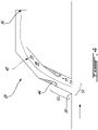
- Fig. 4 presents an example of such a structure 44. More specifically, the structure 44 protrudes partially from the auxiliary duct 26 into the auxiliary passage 34, and in other words, restricts the cross-sectional area of the auxiliary passage 34.
- the structure 44 can be located at an intermediate position between the proximal end 30 and the valve 36. In other words, it can be spaced apart from both the proximal end 30 and from the valve 36 along the length 45 of the cavity 38.
- the structure 44 can be a Venturi-type structure extending axisymmetrically around a central axis or centerline of the auxiliary passage 34, and presenting a greater pressure loss to reverse flow than to forward flow along the auxiliary passage 34.
- auxiliary passage 34 can vary in alternate embodiments.
- the auxiliary passage 34 can be straight instead of curvilinear in an alternate embodiment, and a Venturi-type structure provided within a straight passage can operate similarly to the one illustrated in Fig. 4 .
- the configuration of the auxiliary passage 34 relative to the bypass passage 22 may impart asymmetric features to the flow of air in the air passage 34 when the valve 36 is open. This can be the case, for instance, in the embodiment presented in Figs. 5A to 5D .
- Fig. 5A and 5B show characteristics of the flow which can occur in typical operating conditions when the valve 36 is open.
- a change in the traveling direction of the fluid, the pressurized air occurs when the air traverses the inlet/proximal end 30 and circulates inside the first section of the duct.
- Such a change in flow orientation causes an asymmetry to the flow which can be seen in Fig.
- circulating the auxiliary flow through a curvilinear elbow 48 between the first section 50 and a second section 52 redirects the flow towards an axial orientation, and circulating the flow in the reverse orientation through the same area redirects the flow towards a radially-inward orientation.
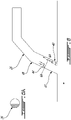
- a structure 44 is introduced in the form of a perforated plate which protrudes partially into the auxiliary passage 34 from the front portion 47 of the auxiliary duct 26, such as presented in section A-A. Occupying the front portion 47 of the auxiliary duct 26 in a region where the forward flow is strongly compressed against the rear portion 40 (as best seen in Fig. 5A and 5B ), the structure has a limited effect on the forward flow. The forward flow essentially "slips" under the structure. However, it has a significant effect on the rearward flow (as best seen in Figs.
- a perforated plate is but one of many possible alternative configurations.
- an embodiment presented in Fig. 7 can use a structure 44 in the form of a louver 51 or a set of louvers to achieve a very similar aerodynamic effect.
- the louver 51 extends obliquely into the auxiliary duct 26 leading to a progressively reducing surface area towards the valve 36, along a given section of the auxiliary duct 26.
- the louver 51 penetrates progressively deeper into the auxiliary passage 34 from the front portion 47 as it progresses the direction of the distal end or valve 36.
- Each of the embodiments presented in Fig. 4 , Fig. 6 and Fig. 7 use a structure 44 which generates asymmetric pressure losses to air flow depending on the orientation of the air flow.
- the embodiment presented in Fig. 4 intrinsically produces asymmetric pressure losses, and can work on a straight duct having uniform flow.
- the embodiments presented in Figs. 6 and 7 use a structure 44 which is structurally asymmetrical relative to a central axis 46 of the auxiliary duct 26, and which harnesses an asymmetry in the flow stemming from the irregular shape of the auxiliary duct 26 or of the flow within it such as which can stem from the configuration of the auxiliary passage 26 relative to the bypass passage 22 to impart asymmetric pressure losses in the different orientations.
- the asymmetry in both orientations of the flow in the portion of the auxiliary duct 26 bearing the structure 44 stems from the pressing of the forward flow and from the pressing of the rearward flow against opposite portions (forward or rearward) given the turning of the flow generated by the scoop 42 and by the elbow 48. More specifically, all these embodiments generate lesser pressure losses to air flowing towards the distal end 32 than pressure losses to air flowing towards the proximal end 30.
- a first distance 53 between the structure 44 and the proximal end 30 of the auxiliary duct 26 can be of more than half of a cross-sectional dimension 54 of the air passage 34 at the proximal end 30.
- the cross-sectional dimension 54 can be a diameter of the air passage at the proximal end 30 if the cross-sectional shape is circular.
- the cross-sectional dimension 54 can be a major dimension of the non-circular shape, a minor dimension of the non-circular shape, or an average between the two.
- the distance 53 between the structure 44 and the proximal end 30 of the auxiliary duct 26 can be of more than the entire cross-sectional dimension 54 of the air passage 34 at the proximal end 30, or even more in other embodiments.
- a method of operation can include a fan circulating 100 an annular bypass flow between a bypass duct 20 and an engine core 24, branching off 102 an auxiliary portion of the bypass flow as an auxiliary flow, including circulating the auxiliary flow through a proximal end 30 of an auxiliary duct 26, along the auxiliary duct 26, and through a distal end 32 of the auxiliary duct 26, closing 104 a valve 36 of the auxiliary duct 26, thereby interrupting said auxiliary flow, and while the valve of the auxiliary duct 26 is closed, a structure 44 extending in the auxiliary duct 26 causing 106 first pressure losses to reverse flow from the valve 36 to the proximal end 30, the structure causing second pressure losses to said auxiliary flow, the second pressure losses being lower than the first pressure losses, preferably 25% lower or more.
- the presence of the structure can impede acoustic resonances at a natural frequency cavity 38 formed by the auxiliary duct 26 between the proximal end 30 and the valve 36 when the valve 36 is closed
- Positioning the structure 44 relatively close to the proximal end 30, while maintaining the structure spaced from the proximal end 30 by at least half the cross-sectional dimension 54 of the auxiliary duct 26, may be one way to achieve this in some embodiments.
- a low velocity "bubble" is formed alongside the front portion 46 of the auxiliary duct 26 downstream of the proximal end 30, it can be strategic to position the structure 44 within that area of forward flow low-velocity bubble.
- the distance 53 between the structure 44 and the proximal end 30 it will be preferred for the distance 53 between the structure 44 and the proximal end 30 to be at least than 10%, preferably at least 20%, preferably at least 30% more or less than the length 45 of the cavity 38 or distance between the proximal end 30 and the valve 36.
- the embodiments described in this document provide non-limiting examples of possible implementations of the present technology.
- the internal structures can be customized to non-circular ducts, the internal structures may be made of smart materials and may be intrinsically activated in response to specific flow parameters or topology, the internal structures may be machined, welded/brazed, moulded or 3D printed into the hosting duct.
- the internal structures may be machined, welded/brazed, moulded or 3D printed into the hosting duct.
Landscapes
- Engineering & Computer Science (AREA)
- Chemical & Material Sciences (AREA)
- Combustion & Propulsion (AREA)
- Mechanical Engineering (AREA)
- General Engineering & Computer Science (AREA)
- Physics & Mathematics (AREA)
- Fluid Mechanics (AREA)
- Health & Medical Sciences (AREA)
- General Health & Medical Sciences (AREA)
- Pulmonology (AREA)
- Aviation & Aerospace Engineering (AREA)
- Structures Of Non-Positive Displacement Pumps (AREA)
Abstract
Description
- The application relates generally to gas turbine engines and, more particularly, to auxiliary ducts of turbofan engines.
- Some turbofan engines have an auxiliary duct branching out from the bypass duct and configured to supply an aircraft system with a flow of pressurized air. The aircraft system can be a pre-cooler of an environment cooling system (ECS) for instance. In some cases, the auxiliary duct can be equipped with a valve to allow selectively opening or closing the auxiliary passage. When the valve is closed, a portion of the auxiliary duct open to the bypass flow can extend between the bypass duct and the valve. While existing auxiliary ducts were satisfactory to a certain degree, there always remains room for improvement.
- In one aspect, there is provided a turbofan engine comprising : a bypass duct forming a bypass passage extending annularly around an axis, the bypass passage extending rearwardly from a fan and around an engine core; an auxiliary duct branching radially outwardly from the bypass duct relative the axis, the auxiliary duct having a proximal end fluidly connecting the bypass duct and a distal end, the auxiliary duct defining an auxiliary passage between the proximal end and the distal end, the auxiliary passage fluidly connecting the bypass passage, a valve activatable to selectively open and close the auxiliary passage, and a structure protruding partially from the auxiliary duct into the auxiliary passage, the structure spaced apart from the proximal end, between the proximal end and the valve, the structure generating lesser pressure losses when flow in the auxiliary passage is directed towards the distal end than when the flow is directed towards the proximal end.
- In another aspect, there is provided a method of operating a turbofan engine comprising : a fan circulating an annular bypass flow between a bypass duct and an engine core; branching off an auxiliary portion of a bypass flow as an auxiliary flow, including circulating the auxiliary flow through a proximal end of an auxiliary duct, along the auxiliary duct, and through a distal end of the auxiliary duct, closing a valve of the auxiliary duct, thereby interrupting said auxiliary flow, and while the valve of the auxiliary duct is closed, a structure extending in the auxiliary duct causing first pressure losses to reverse flow from the valve to the proximal end, the structure causing second pressure losses to said auxiliary flow, the second pressure losses being lower than the first pressure losses.
- In a further aspect, there is provided an auxiliary duct system comprising : an auxiliary duct defining an auxiliary passage between a proximal end and a distal end, a valve activatable to selectively open and close the auxiliary passage, and a structure reducing the cross-sectional area of the auxiliary passage, the structure spaced apart from the proximal end, between the proximal end and the valve, the structure generating lesser pressure losses when flow in the auxiliary passage is directed towards the distal end than when the flow is directed towards the proximal end.
- Reference is now made to the accompanying figures in which:
-
Fig. 1 is a schematic cross-sectional view of a gas turbine engine; -
Fig. 2A and 2B are diagrams of pressure vs. mass flow for two different auxiliary duct configurations; -
Fig. 3 is a schematic cross-sectional view of an example auxiliary duct configuration; -
Fig. 4 is a schematic cross-sectional view of another example auxiliary duct configuration; -
Figs 5A-5D are graphs mapping speed (5A, 5C) and pressure (5B, 5D) of forward flow (5A, 5B) and reverse flow (5C, 5D) in accordance with one example auxiliary duct configuration; -
Fig. 6 is a schematic cross-sectional view of another example auxiliary duct configuration, withFig. 6A being a cross-sectional view taken alonglines 6A-6A ofFig. 6 ; -
Fig. 7 is a schematic cross-sectional view of another example auxiliary duct configuration, and -
Fig. 8 is a flow chart of a method of operating a turbofan engine in accordance with an embodiment. -
Fig. 1 illustrates agas turbine engine 10 of a type preferably provided for use in subsonic flight, generally comprising in serial flow communication afan 12 through which ambient air is propelled, acompressor section 14 for pressurizing the air, acombustor 16 in which the compressed air is mixed with fuel and ignited for generating an annular stream of hot combustion gases around theengine axis 11, and aturbine section 18 for extracting energy from the combustion gases. Thegas turbine engine 10 is of the turbofan type, and therefore has anannular bypass duct 20. The bypass duct delimits abypass passage 22 extending annularly around a theaxis 11. A forward and a rear directions can be defined along theaxis 11. Thebypass passage 22 extends rearwardly from thefan 12 around and along anengine core 24. A first portion of the flow from thefan 12 is directed to theengine core 24 as a working fluid for theturbine section 18, and a second portion of the flow from thefan 12 is directed to thebypass passage 22 in the form of a bypass flow, for thrust. - In some embodiments, it can be required to provide the
gas turbine engine 10 with anauxiliary duct 26 which branches off from thebypass duct 20. Such anauxiliary duct 26 can serve to supply pressurized air to anaircraft system 28 such as an environmental cooling system (ECS) pre-cooler, or any other suitable aircraft system, for instance. Theauxiliary duct 26 can have aproximal end 30 fluidly connecting thebypass duct 20, and adistal end 32 which can directly or indirectly connect to theaircraft system 28. Theauxiliary duct 26 forms anauxiliary passage 34 from theproximal end 30 to thedistal end 32, theauxiliary passage 34 being fluidly connected to thebypass passage 22 at theproximal end 30. - Depending on the embodiment, the amount of air to be supplied via the
auxiliary passage 34 may need to be substantial. This auxiliary flow may be subject to various pressure losses or aerodynamic transformations which make it lose some or all of its efficiency from the point of view of propulsion. The circulation of air through theauxiliary duct 26 can thus be associated to a trade-off of loss in engine efficiency. Theaircraft system 28 may not be continuously in operation, or may not continuously require the supply of auxiliary air. While the loss in engine efficiency may be considered a suitable trade-off during operation of theaircraft system 28, the loss may be more undesirable when the auxiliary air is not required by theaircraft system 28. - To mitigate such undesired losses of engine efficiency, a
valve 36 can be provided in theauxiliary duct 26 and used to selectively open or close theauxiliary passage 34 as a function of the auxiliary air requirements of theaircraft system 28. For various reasons, it may not be feasible or otherwise suitable to position the valve directly at theproximal end 30. In such cases, thevalve 36 is positioned at thedistal end 32, or at an intermediate location along the length of theauxiliary passage 34, between theproximal end 30 and thedistal end 32. In such cases, a portion of theauxiliary duct 26 extending between theproximal end 30 and thevalve 36 can form acavity 38 which is in fluid communication with thebypass passage 22 when the valve is closed. - Such a configuration can help in successfully mitigating undesired losses by preventing or significantly limiting the flow of auxiliary air through the
auxiliary duct 26, forcing it instead into the downstream portion of thebypass passage 22 where it can serve for thrust. However, the presence of thecavity 38 may not be ideal from an dynamic perspective. In particular, such anelongated cavity 38 can have one or more resonance frequencies, such as a natural frequency and harmonics thereof, with the pressurized air medium, and the highly dynamic flow of air in thebypass duct 22 adjacent theproximal end 30 can represent a driving excitation for the resonance frequency. High energy air vibrations at the resonance frequency(ies) associated to variations of flow and of air pressure in thecavity 38 can be an undesired source of noise, or even of potential structural failure. - The interface between the
auxiliary duct 26 and thebypass duct 20 can be configured in a manner that some dynamic pressure recovery from thebypass passage 22 occurs when thevalve 36 is open. A typical curve of the pressure in theauxiliary duct 26 as a function of the mass flow circulating through it is depicted inFigure 2A . Large forward flow is achieved when there is low back pressure, while large back pressure is required in order to reverse the flow. In an embodiment, a source of the resonance can be attributed to the sideways "s"-shape of the curve near zero flow, where for small forward flow larger pressure is seen in the auxiliary duct as there is some dynamic pressure recovery, while to drive flow in the reverse direction only sufficient pressure to overcome the static pressure in the bypass passage is required. When the valve is closed, a hysteresis can develop corresponding red-highlighted area in the curve which can lead to large intensity acoustic tones. - To eliminate the acoustic resonance it can be desired to modify the shape of the pressure curve such as to reduce or eliminate possibility of hysteresis as depicted in the curve in
Fig. 2B . - The more the interface between the
auxiliary passage 26 and thebypass passage 20 at theproximal end 30 is optimized from the point of view of pressure recovery, the greater the tendency to generate large acoustic tones may be. For instance, an example auxiliary passage shape is shown inFig 3 where therear portion 40 of theauxiliary duct 26 penetrates radially to a certain extent into thebypass passage 22 forming ascoop 42 which redirects a portion of the axially incoming bypass flow into the radially outward orientation of a first section of theauxiliary passage 34. Indeed, in this embodiment, to achieve sufficient flow, thescoop 42 is designed to reduce the pressure losses entering theauxiliary duct 26 and to recover some dynamic pressure from the bypass flow. Accordingly, circulating the auxiliary portion of the bypass flow through acurvilinear scoop 42 having a forward facing inlet (facing the fan 12) can preserve flow momentum from the bypass flow in a first section of theauxiliary duct 26. - In one embodiment, it can be desired to address the occurrences of resonances by perturbing the flow near the
proximal end 30. Such an approach can consist of introducing a fence or a louver directly at theproximal end 30 of theauxiliary duct 26, at the inlet. Such an approach may have a suitable effect from the point of view of avoiding large intensity acoustic tones, but may, however, be detrimental from the point of view of pressure recovery when thevalve 36 is open. Accordingly, such an approach may impede flow rate momentum through theauxiliary duct 26 in situations where momentum through theauxiliary duct 26 is preferably optimized. Such an approach may thus leave a want for improvement from the point of view of dynamic pressure recovery. - It was conceived that introducing a
structure 44 which generates asymmetrical losses to the circulation of air in theauxiliary duct 26, and more specifically a greater loss in the reverse flow orientation (towards the proximal end 30) than in the forward flow orientation (towards thevalve 36 or distal end 32) along theauxiliary passage 34, could be better than the previous approach. Indeed, such an approach can be optimized to limit losses in the forward flow orientation (i.e. from theproximal end 30 to the aircraft system 28), which favors pressure recovery and momentum when thevalve 36 is open, while increasing losses/impeding circulation in the reverse orientation (i.e. back to theproximal end 30 from the valve 36), thus avoiding, or mitigating, the formation of a high energy resonance when thevalve 36 is closed. -
Fig. 4 presents an example of such astructure 44. More specifically, thestructure 44 protrudes partially from theauxiliary duct 26 into theauxiliary passage 34, and in other words, restricts the cross-sectional area of theauxiliary passage 34. Thestructure 44 can be located at an intermediate position between theproximal end 30 and thevalve 36. In other words, it can be spaced apart from both theproximal end 30 and from thevalve 36 along thelength 45 of thecavity 38. In the embodiment presented inFig. 4 , thestructure 44 can be a Venturi-type structure extending axisymmetrically around a central axis or centerline of theauxiliary passage 34, and presenting a greater pressure loss to reverse flow than to forward flow along theauxiliary passage 34. It will be understood that other aerodynamic structures may lead to suitable effects and even be preferred in other embodiments. Moreover, the shape of theauxiliary passage 34 can vary in alternate embodiments. For instance, theauxiliary passage 34 can be straight instead of curvilinear in an alternate embodiment, and a Venturi-type structure provided within a straight passage can operate similarly to the one illustrated inFig. 4 . - In some embodiments, the configuration of the
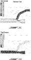
auxiliary passage 34 relative to thebypass passage 22 may impart asymmetric features to the flow of air in theair passage 34 when thevalve 36 is open. This can be the case, for instance, in the embodiment presented inFigs. 5A to 5D .Fig. 5A and 5B , in particular, show characteristics of the flow which can occur in typical operating conditions when thevalve 36 is open. Given the fact that theauxiliary duct 26 branches off from thebypass duct 20 radially outwardly, a change in the traveling direction of the fluid, the pressurized air, occurs when the air traverses the inlet/proximal end 30 and circulates inside the first section of the duct. Such a change in flow orientation causes an asymmetry to the flow which can be seen inFig. 5A and 5B . Indeed, the speed and pressure of the fluid immediately downstream of the proximal end is significantly greater alongside therear portion 40 of theauxiliary passage 26 than along thefront portion 47 of theauxiliary passage 26. In the reverse flow orientation (Figs. 5C, 5D ), however, such asymmetry may be absent, or even reversed. Indeed, in a scenario such as the one illustrated, where an oppositely orientedelbow 48 is defined between afirst section 50 of theauxiliary duct 26 and asecond section 52. Indeed, in the illustrated embodiment, air progressing in the reverse direction will become pressed against theforward portion 46 of theauxiliary duct 26 rather than therear portion 40 as it exits theelbow 48. Indeed, in an embodiment such as illustratedFig. 5A , circulating the auxiliary flow through acurvilinear elbow 48 between thefirst section 50 and asecond section 52 redirects the flow towards an axial orientation, and circulating the flow in the reverse orientation through the same area redirects the flow towards a radially-inward orientation. - In a scenario such as the one illustrated, when the flow characteristics are not the same in the forward and the reverse directions, introducing a
structure 44 which would have a symmetrical effect on a uniform flow may have a suitable asymmetrical effect given the differing flow configurations in the opposite flow orientations. Accordingly, such a concept can be harnessed to provide greater pressure losses in the reverse orientation than in the forward orientation. - An example of an embodiment harnessing this concept is illustrated in
Fig. 6 . In the embodiment presented inFig. 6 , astructure 44 is introduced in the form of a perforated plate which protrudes partially into theauxiliary passage 34 from thefront portion 47 of theauxiliary duct 26, such as presented in section A-A. Occupying thefront portion 47 of theauxiliary duct 26 in a region where the forward flow is strongly compressed against the rear portion 40 (as best seen inFig. 5A and 5B ), the structure has a limited effect on the forward flow. The forward flow essentially "slips" under the structure. However, it has a significant effect on the rearward flow (as best seen inFigs. 5C and 5D ) which is compressed against thefront portion 47 of the auxiliary duct as it exits theelbow 48. Sufficient energy can be dissipated by the perforated baffle as the flow exits in the reverse direction to reduce or eliminate the acoustic resonance. - The example of a perforated plate is but one of many possible alternative configurations. For instance, an embodiment presented in
Fig. 7 can use astructure 44 in the form of alouver 51 or a set of louvers to achieve a very similar aerodynamic effect. InFig. 7 , thelouver 51 extends obliquely into theauxiliary duct 26 leading to a progressively reducing surface area towards thevalve 36, along a given section of theauxiliary duct 26. In other words, thelouver 51 penetrates progressively deeper into theauxiliary passage 34 from thefront portion 47 as it progresses the direction of the distal end orvalve 36. - Each of the embodiments presented in
Fig. 4 ,Fig. 6 andFig. 7 use astructure 44 which generates asymmetric pressure losses to air flow depending on the orientation of the air flow. The embodiment presented inFig. 4 intrinsically produces asymmetric pressure losses, and can work on a straight duct having uniform flow. The embodiments presented inFigs. 6 and7 use astructure 44 which is structurally asymmetrical relative to acentral axis 46 of theauxiliary duct 26, and which harnesses an asymmetry in the flow stemming from the irregular shape of theauxiliary duct 26 or of the flow within it such as which can stem from the configuration of theauxiliary passage 26 relative to thebypass passage 22 to impart asymmetric pressure losses in the different orientations. More specifically, in these embodiments, the asymmetry in both orientations of the flow in the portion of theauxiliary duct 26 bearing thestructure 44 stems from the pressing of the forward flow and from the pressing of the rearward flow against opposite portions (forward or rearward) given the turning of the flow generated by thescoop 42 and by theelbow 48. More specifically, all these embodiments generate lesser pressure losses to air flowing towards thedistal end 32 than pressure losses to air flowing towards theproximal end 30. - In all the embodiments presented above, as evidenced in
Fig. 4 for instance, thestructure 44 generating the asymmetric pressure losses is not located at theproximal end 30, but recessed therefrom into theauxiliary passage 34. Afirst distance 53 between thestructure 44 and theproximal end 30 of theauxiliary duct 26 can be of more than half of across-sectional dimension 54 of theair passage 34 at theproximal end 30. Thecross-sectional dimension 54 can be a diameter of the air passage at theproximal end 30 if the cross-sectional shape is circular. If the cross-sectional shape is non-circular, thecross-sectional dimension 54 can be a major dimension of the non-circular shape, a minor dimension of the non-circular shape, or an average between the two. Thedistance 53 between thestructure 44 and theproximal end 30 of theauxiliary duct 26 can be of more than the entirecross-sectional dimension 54 of theair passage 34 at theproximal end 30, or even more in other embodiments. - Referring to
Fig. 8 , a method of operation can include a fan circulating 100 an annular bypass flow between abypass duct 20 and anengine core 24, branching off 102 an auxiliary portion of the bypass flow as an auxiliary flow, including circulating the auxiliary flow through aproximal end 30 of anauxiliary duct 26, along theauxiliary duct 26, and through adistal end 32 of theauxiliary duct 26, closing 104 avalve 36 of theauxiliary duct 26, thereby interrupting said auxiliary flow, and while the valve of theauxiliary duct 26 is closed, astructure 44 extending in theauxiliary duct 26 causing 106 first pressure losses to reverse flow from thevalve 36 to theproximal end 30, the structure causing second pressure losses to said auxiliary flow, the second pressure losses being lower than the first pressure losses, preferably 25% lower or more. The presence of the structure can impede acoustic resonances at anatural frequency cavity 38 formed by theauxiliary duct 26 between theproximal end 30 and thevalve 36 when thevalve 36 is closed. - In some embodiments, it can be preferred to avoid inducing not only resonances at a natural frequency of the
cavity 38, but also secondary resonances, which may be considered as "harmonics". This can be achieved in some embodiments by the choice of location at which thestructure 44 is placed along thelength 45 of thecavity 38. Indeed, positioning the structure at exactly half of thelength 45 of the cavity 38 (thecavity 38 being is the "acoustically active" portion of theauxiliary duct 26 extending between theproximal end 30 and thevalve 36 when thevalve 36 is closed) may successfully impede resonance at the natural frequency, while allowing relatively strong harmonics at twice the natural frequency or at other higher frequencies. It can be desired to strategically position the structure at a location where it will impede all significant resonances, which can be referred to as resonances occurring at frequencies of interest. Positioning thestructure 44 relatively close to theproximal end 30, while maintaining the structure spaced from theproximal end 30 by at least half thecross-sectional dimension 54 of theauxiliary duct 26, may be one way to achieve this in some embodiments. In particular, in an embodiment such as shown inFig. 5A and 5B , where a low velocity "bubble" is formed alongside thefront portion 46 of theauxiliary duct 26 downstream of theproximal end 30, it can be strategic to position thestructure 44 within that area of forward flow low-velocity bubble. In most embodiments, it will be preferred for thedistance 53 between thestructure 44 and theproximal end 30 to be at least than 10%, preferably at least 20%, preferably at least 30% more or less than thelength 45 of thecavity 38 or distance between theproximal end 30 and thevalve 36. To avoid higher energy harmonics, it can be preferred to position the structure at an irrational fraction of thelength 45 of thecavity 38. It can also be preferred to position thestructure 44 closer to theproximal end 30 than to thevalve 36 in some embodiments. - The embodiments described in this document provide non-limiting examples of possible implementations of the present technology. Upon review of the present disclosure, a person of ordinary skill in the art will recognize that changes may be made to the embodiments described herein without departing from the scope of the present technology. For example, the internal structures can be customized to non-circular ducts, the internal structures may be made of smart materials and may be intrinsically activated in response to specific flow parameters or topology, the internal structures may be machined, welded/brazed, moulded or 3D printed into the hosting duct. Yet further modifications could be implemented by a person of ordinary skill in the art in view of the present disclosure, which modifications would be within the scope of the present technology.
Claims (15)
- A turbofan engine (10) comprising:a bypass duct (20) forming a bypass passage (22) extending annularly around an axis (11), the bypass passage (22) extending rearwardly from a fan (12) and around an engine core (24);an auxiliary duct (26) branching radially outwardly from the bypass duct (20) relative the axis (11), the auxiliary duct (26) having a proximal end (30) fluidly connecting the bypass duct (20) and a distal end (32), the auxiliary duct (26) defining an auxiliary passage (34) between the proximal end (30) and the distal end (32), the auxiliary passage (34) fluidly connecting the bypass passage (22);a valve activatable to selectively open and close the auxiliary passage (34); anda structure (44) protruding partially from the auxiliary duct (26) into the auxiliary passage (34), the structure (44) spaced apart from the proximal end (30), between the proximal end (30) and the valve (36), the structure (44) generating lesser pressure losses when flow in the auxiliary passage (34) is directed towards the distal end (32) than when the flow is directed towards the proximal end (30).
- The turbofan engine (10) of claim 1, wherein a distance (53) between the structure (44) and the proximal end (30) is greater than half of a cross-sectional dimension (54) of the air passage at the proximal end (30), optionally greater than the cross-sectional dimension (54).
- The turbofan engine (10) of claim 1 or 2, wherein a first distance (53) defined between the proximal end (30) and the structure (44) is at least 10% more or less than half of a second distance (45) defined between the proximal end (30) and the valve (36), along a length (45) of the auxiliary passage (34).
- The turbofan engine (10) of claim 3, wherein the first distance (53) is at least 20% more or less than half of the second distance (45), or at least 30% more or less than half of the second distance (45).
- The turbofan engine (10) of any preceding claim, wherein the auxiliary duct (26) has a first section (50) extending radially outwardly from the proximal end (30), a second section (52) extending axially towards the distal end (32), and an elbow (48) between the first section (50) and the second section (52).
- The turbofan engine (10) of any preceding claim, wherein the structure (44) protrudes from a forward portion of the auxiliary duct (26), the structure (44) being in the first section (50) and partially obstructing the flow.
- The turbofan engine (10) of any preceding claim, wherein the structure (44) is an apertured plate extending transversally to a length (45) of the auxiliary passage (34).
- The turbofan engine (10) of any of claims 1 to 6, wherein the structure (44) is a louver (51) extending progressively deeper into the auxiliary duct (26) in a direction towards the distal end (32).
- The turbofan engine (10) of any preceding claim, wherein the auxiliary duct (26) has a scoop (42) at the proximal end (30), the scoop (42) penetrating into the bypass passage (22) and having an inlet oriented forwardly towards the fan (12).
- The turbofan engine (10) of any preceding claim, wherein the pressure losses when flow is directed towards the distal end (32) are at least 25% lesser than when flow is directed towards the proximal end (30).
- The turbofan engine (10) of any preceding claim, wherein the distal end (32) is fluidly connected to an environmental control system pre-cooler.
- A method of operating a turbofan engine (10) comprising :a fan (12) circulating an annular bypass flow between a bypass duct (20) and an engine core (24);branching off an auxiliary portion of the bypass flow as an auxiliary flow, including circulating the auxiliary flow through a proximal end (30) of an auxiliary duct (26), along the auxiliary duct (26), and through a distal end (32) of the auxiliary duct (26);closing a valve (36) of the auxiliary duct (26), thereby interrupting said auxiliary flow; andwhile the valve (36) of the auxiliary duct (26) is closed, a structure (44) extending in the auxiliary duct (26) causing first pressure losses to reverse flow from the valve to the proximal end (30), the structure (44) causing second pressure losses to said auxiliary flow, the second pressure losses being lower than the first pressure losses, wherein said causing first pressure losses includes causing at least 25% greater pressure losses to flow in the reverse orientation than to flow towards the valve (36).
- The method of claim 12, wherein said structure(44):impedes acoustic resonances at a natural frequency of the auxiliary duct (26) between the proximal end (30) and the valve (36) when the valve (36) is closed; and/oris spaced apart from the proximal end (30) by at least half of a cross-sectional dimension (54) of the auxiliary flow at the proximal end (30).
- The method of claim 12 or 13, wherein said branching off an auxiliary portion of the bypass flow includes circulating the auxiliary portion of the bypass flow through a curvilinear scoop (42) having a forward facing inlet, thereby preserving momentum from the bypass flow in a first section (50) of the auxiliary flow, the first section (50) extending radially outwardly relative an axis of the annular bypass flow, and optionally further comprising circulating the auxiliary flow through a curvilinear elbow (48) between the first section (50) and a second section (52), thereby redirecting the auxiliary flow towards an axial orientation, wherein said structure (44) extends in a forward half of the first section (50), at an intermediate location along the first section (50).
- An auxiliary duct (26) system comprising :an auxiliary duct (26) defining an auxiliary passage (34) between a proximal end (30) and a distal end (32);a valve (36) activatable to selectively open and close the auxiliary passage (34); anda structure (44) reducing the cross-sectional (54) area of the auxiliary passage (34), the structure (44) spaced apart from the proximal end (30), between the proximal end (30) and the valve (36), the structure (44) generating lesser pressure losses when flow in the auxiliary passage (34) is directed towards the distal end (32) than when the flow is directed towards the proximal end (30).
Applications Claiming Priority (1)
| Application Number | Priority Date | Filing Date | Title |
|---|---|---|---|
| US17/344,185 US11603796B2 (en) | 2021-06-10 | 2021-06-10 | Turbofan engine and method of operating same |
Publications (2)
| Publication Number | Publication Date |
|---|---|
| EP4102041A1 true EP4102041A1 (en) | 2022-12-14 |
| EP4102041B1 EP4102041B1 (en) | 2025-04-16 |
Family
ID=82019580
Family Applications (1)
| Application Number | Title | Priority Date | Filing Date |
|---|---|---|---|
| EP22178506.6A Active EP4102041B1 (en) | 2021-06-10 | 2022-06-10 | Turbofan engine and method of operating same |
Country Status (3)
| Country | Link |
|---|---|
| US (1) | US11603796B2 (en) |
| EP (1) | EP4102041B1 (en) |
| CA (1) | CA3160900A1 (en) |
Cited By (1)
| Publication number | Priority date | Publication date | Assignee | Title |
|---|---|---|---|---|
| DE102022115665A1 (en) | 2022-06-23 | 2023-12-28 | Rolls-Royce Deutschland Ltd & Co Kg | Air intake |
Families Citing this family (7)
| Publication number | Priority date | Publication date | Assignee | Title |
|---|---|---|---|---|
| DE102022115659A1 (en) * | 2022-06-23 | 2023-12-28 | Rolls-Royce Deutschland Ltd & Co Kg | Air intake |
| US12618378B2 (en) | 2022-11-01 | 2026-05-05 | General Electric Company | Gas turbine engine |
| US12173669B1 (en) | 2023-08-18 | 2024-12-24 | General Electric Company | Turbine engine with fan bypass water injection to augment thrust |
| US12240624B1 (en) | 2023-09-06 | 2025-03-04 | General Electric Company | Aircraft gas turbine engine with heated fuel to assist combustion |
| US12276229B2 (en) | 2023-09-08 | 2025-04-15 | General Electric Company | Method of operating a turbine engine having a bleed system |
| US12312997B2 (en) * | 2023-09-08 | 2025-05-27 | General Electric Company | Turbine engine having a bleed system |
| US12241406B1 (en) | 2023-12-13 | 2025-03-04 | Geneeral Electric Company | Turbine engine including a steam system |
Citations (2)
| Publication number | Priority date | Publication date | Assignee | Title |
|---|---|---|---|---|
| US20100126182A1 (en) * | 2008-11-21 | 2010-05-27 | Honeywell International Inc. | Flush inlet scoop design for aircraft bleed air system |
| EP2415992A2 (en) * | 2010-08-04 | 2012-02-08 | Rolls-Royce plc | Ventilation Inlet |
Family Cites Families (8)
| Publication number | Priority date | Publication date | Assignee | Title |
|---|---|---|---|---|
| US3024935A (en) | 1960-02-25 | 1962-03-13 | Vinick George | Banana packing means |
| US7966831B2 (en) * | 2007-08-28 | 2011-06-28 | General Electric Company | Apparatus and method for suppressing dynamic pressure instability in bleed duct |
| US9109514B2 (en) * | 2012-01-10 | 2015-08-18 | Hamilton Sundstrand Corporation | Air recovery system for precooler heat-exchanger |
| FR3003024B1 (en) * | 2013-03-11 | 2019-09-06 | Safran Aircraft Engines | HEAT EXCHANGER OF A TURBOMACHINE |
| FR3024494B1 (en) * | 2014-07-31 | 2016-07-22 | Airbus Operations Sas | AIRCRAFT TURBOMACHINE COMPRISING A DEFLECTOR |
| PL232261B1 (en) | 2015-11-02 | 2019-05-31 | Gen Electric | Method and the system for decreasing resonance in a chamber |
| US10487744B2 (en) * | 2016-05-23 | 2019-11-26 | United Technologies Corporation | Fence for duct tone mitigation |
| US10823055B2 (en) | 2016-08-08 | 2020-11-03 | Pratt & Whitney Canada Corp. | Bypass duct louver for noise mitigation |
-
2021
- 2021-06-10 US US17/344,185 patent/US11603796B2/en active Active
-
2022
- 2022-05-27 CA CA3160900A patent/CA3160900A1/en active Pending
- 2022-06-10 EP EP22178506.6A patent/EP4102041B1/en active Active
Patent Citations (2)
| Publication number | Priority date | Publication date | Assignee | Title |
|---|---|---|---|---|
| US20100126182A1 (en) * | 2008-11-21 | 2010-05-27 | Honeywell International Inc. | Flush inlet scoop design for aircraft bleed air system |
| EP2415992A2 (en) * | 2010-08-04 | 2012-02-08 | Rolls-Royce plc | Ventilation Inlet |
Cited By (1)
| Publication number | Priority date | Publication date | Assignee | Title |
|---|---|---|---|---|
| DE102022115665A1 (en) | 2022-06-23 | 2023-12-28 | Rolls-Royce Deutschland Ltd & Co Kg | Air intake |
Also Published As
| Publication number | Publication date |
|---|---|
| EP4102041B1 (en) | 2025-04-16 |
| US20220397058A1 (en) | 2022-12-15 |
| US11603796B2 (en) | 2023-03-14 |
| CA3160900A1 (en) | 2022-12-10 |
Similar Documents
| Publication | Publication Date | Title |
|---|---|---|
| EP4102041B1 (en) | Turbofan engine and method of operating same | |
| US8024935B2 (en) | Flush inlet scoop design for aircraft bleed air system | |
| US7137245B2 (en) | High area-ratio inter-turbine duct with inlet blowing | |
| JP6018293B2 (en) | High pressure silencer | |
| US5454222A (en) | Small gas turbine engine having enhanced fuel economy | |
| JP6063246B2 (en) | Compact high pressure exhaust silencer | |
| US5832715A (en) | Small gas turbine engine having enhanced fuel economy | |
| JP4948965B2 (en) | Multi-slot inter-turbine duct assembly for use in turbine engines | |
| CN108930557B (en) | Method and system for auxiliary guide vanes at the leading edge of compressor guide vanes | |
| JP5080815B2 (en) | Exhaust duct flow splitter system | |
| JP6378736B2 (en) | Compression cowl for jet engine exhaust | |
| US8839805B2 (en) | Passive boundary layer bleed system for nacelle inlet airflow control | |
| CN106870161A (en) | Method and system for mitigating chamber resonance | |
| JP2009052561A (en) | Apparatus and method for suppressing dynamic pressure instability in a bleed duct | |
| EP2077963B1 (en) | Gas turbine nacelle comprising a passive boundary layer bleed system | |
| JP6126095B2 (en) | Nozzle structure and manufacturing method of nozzle structure | |
| CA2669280C (en) | Turbofan gas turbine engine and nacelle arrangement | |
| CA2567940A1 (en) | Methods and apparatuses for gas turbine engines | |
| CN105736149A (en) | Ducted cowl support for a gas turbine engine | |
| JP6180005B2 (en) | Nozzle structure and manufacturing method of nozzle structure | |
| JP4101080B2 (en) | Turbofan jet engine. | |
| EP4650662A1 (en) | Turbine engine having a damper | |
| US12366203B1 (en) | Turbine engine having a multicavity damper | |
| US11859537B2 (en) | Gas turbine engine | |
| KR20010085016A (en) | Jet engine using exhaust gas |
Legal Events
| Date | Code | Title | Description |
|---|---|---|---|
| PUAI | Public reference made under article 153(3) epc to a published international application that has entered the european phase |
Free format text: ORIGINAL CODE: 0009012 |
|
| STAA | Information on the status of an ep patent application or granted ep patent |
Free format text: STATUS: THE APPLICATION HAS BEEN PUBLISHED |
|
| AK | Designated contracting states |
Kind code of ref document: A1 Designated state(s): AL AT BE BG CH CY CZ DE DK EE ES FI FR GB GR HR HU IE IS IT LI LT LU LV MC MK MT NL NO PL PT RO RS SE SI SK SM TR |
|
| STAA | Information on the status of an ep patent application or granted ep patent |
Free format text: STATUS: REQUEST FOR EXAMINATION WAS MADE |
|
| 17P | Request for examination filed |
Effective date: 20230614 |
|
| RBV | Designated contracting states (corrected) |
Designated state(s): AL AT BE BG CH CY CZ DE DK EE ES FI FR GB GR HR HU IE IS IT LI LT LU LV MC MK MT NL NO PL PT RO RS SE SI SK SM TR |
|
| GRAP | Despatch of communication of intention to grant a patent |
Free format text: ORIGINAL CODE: EPIDOSNIGR1 |
|
| STAA | Information on the status of an ep patent application or granted ep patent |
Free format text: STATUS: GRANT OF PATENT IS INTENDED |
|
| RIC1 | Information provided on ipc code assigned before grant |
Ipc: F02K 3/06 20060101ALI20241023BHEP Ipc: F02C 6/06 20060101AFI20241023BHEP |
|
| INTG | Intention to grant announced |
Effective date: 20241112 |
|
| GRAS | Grant fee paid |
Free format text: ORIGINAL CODE: EPIDOSNIGR3 |
|
| GRAA | (expected) grant |
Free format text: ORIGINAL CODE: 0009210 |
|
| STAA | Information on the status of an ep patent application or granted ep patent |
Free format text: STATUS: THE PATENT HAS BEEN GRANTED |
|
| AK | Designated contracting states |
Kind code of ref document: B1 Designated state(s): AL AT BE BG CH CY CZ DE DK EE ES FI FR GB GR HR HU IE IS IT LI LT LU LV MC MK MT NL NO PL PT RO RS SE SI SK SM TR |
|
| REG | Reference to a national code |
Ref country code: GB Ref legal event code: FG4D |
|
| REG | Reference to a national code |
Ref country code: CH Ref legal event code: EP |
|
| REG | Reference to a national code |
Ref country code: IE Ref legal event code: FG4D |
|
| REG | Reference to a national code |
Ref country code: DE Ref legal event code: R096 Ref document number: 602022013130 Country of ref document: DE |
|
| PGFP | Annual fee paid to national office [announced via postgrant information from national office to epo] |
Ref country code: AT Payment date: 20250721 Year of fee payment: 4 |
|
| REG | Reference to a national code |
Ref country code: NL Ref legal event code: MP Effective date: 20250416 |
|
| PG25 | Lapsed in a contracting state [announced via postgrant information from national office to epo] |
Ref country code: NL Free format text: LAPSE BECAUSE OF FAILURE TO SUBMIT A TRANSLATION OF THE DESCRIPTION OR TO PAY THE FEE WITHIN THE PRESCRIBED TIME-LIMIT Effective date: 20250416 |
|
| REG | Reference to a national code |
Ref country code: AT Ref legal event code: MK05 Ref document number: 1785838 Country of ref document: AT Kind code of ref document: T Effective date: 20250416 |
|
| PG25 | Lapsed in a contracting state [announced via postgrant information from national office to epo] |
Ref country code: FI Free format text: LAPSE BECAUSE OF FAILURE TO SUBMIT A TRANSLATION OF THE DESCRIPTION OR TO PAY THE FEE WITHIN THE PRESCRIBED TIME-LIMIT Effective date: 20250416 Ref country code: ES Free format text: LAPSE BECAUSE OF FAILURE TO SUBMIT A TRANSLATION OF THE DESCRIPTION OR TO PAY THE FEE WITHIN THE PRESCRIBED TIME-LIMIT Effective date: 20250416 Ref country code: PT Free format text: LAPSE BECAUSE OF FAILURE TO SUBMIT A TRANSLATION OF THE DESCRIPTION OR TO PAY THE FEE WITHIN THE PRESCRIBED TIME-LIMIT Effective date: 20250818 |
|
| REG | Reference to a national code |
Ref country code: LT Ref legal event code: MG9D |
|
| PG25 | Lapsed in a contracting state [announced via postgrant information from national office to epo] |
Ref country code: NO Free format text: LAPSE BECAUSE OF FAILURE TO SUBMIT A TRANSLATION OF THE DESCRIPTION OR TO PAY THE FEE WITHIN THE PRESCRIBED TIME-LIMIT Effective date: 20250716 Ref country code: GR Free format text: LAPSE BECAUSE OF FAILURE TO SUBMIT A TRANSLATION OF THE DESCRIPTION OR TO PAY THE FEE WITHIN THE PRESCRIBED TIME-LIMIT Effective date: 20250717 |
|
| PG25 | Lapsed in a contracting state [announced via postgrant information from national office to epo] |
Ref country code: PL Free format text: LAPSE BECAUSE OF FAILURE TO SUBMIT A TRANSLATION OF THE DESCRIPTION OR TO PAY THE FEE WITHIN THE PRESCRIBED TIME-LIMIT Effective date: 20250416 |
|
| PG25 | Lapsed in a contracting state [announced via postgrant information from national office to epo] |
Ref country code: BG Free format text: LAPSE BECAUSE OF FAILURE TO SUBMIT A TRANSLATION OF THE DESCRIPTION OR TO PAY THE FEE WITHIN THE PRESCRIBED TIME-LIMIT Effective date: 20250416 |
|
| PG25 | Lapsed in a contracting state [announced via postgrant information from national office to epo] |
Ref country code: AT Free format text: LAPSE BECAUSE OF FAILURE TO SUBMIT A TRANSLATION OF THE DESCRIPTION OR TO PAY THE FEE WITHIN THE PRESCRIBED TIME-LIMIT Effective date: 20250416 Ref country code: HR Free format text: LAPSE BECAUSE OF FAILURE TO SUBMIT A TRANSLATION OF THE DESCRIPTION OR TO PAY THE FEE WITHIN THE PRESCRIBED TIME-LIMIT Effective date: 20250416 |
|
| PG25 | Lapsed in a contracting state [announced via postgrant information from national office to epo] |
Ref country code: RS Free format text: LAPSE BECAUSE OF FAILURE TO SUBMIT A TRANSLATION OF THE DESCRIPTION OR TO PAY THE FEE WITHIN THE PRESCRIBED TIME-LIMIT Effective date: 20250716 |
|
| PG25 | Lapsed in a contracting state [announced via postgrant information from national office to epo] |
Ref country code: IS Free format text: LAPSE BECAUSE OF FAILURE TO SUBMIT A TRANSLATION OF THE DESCRIPTION OR TO PAY THE FEE WITHIN THE PRESCRIBED TIME-LIMIT Effective date: 20250816 |
|
| PG25 | Lapsed in a contracting state [announced via postgrant information from national office to epo] |
Ref country code: LV Free format text: LAPSE BECAUSE OF FAILURE TO SUBMIT A TRANSLATION OF THE DESCRIPTION OR TO PAY THE FEE WITHIN THE PRESCRIBED TIME-LIMIT Effective date: 20250416 |
|
| PG25 | Lapsed in a contracting state [announced via postgrant information from national office to epo] |
Ref country code: DK Free format text: LAPSE BECAUSE OF FAILURE TO SUBMIT A TRANSLATION OF THE DESCRIPTION OR TO PAY THE FEE WITHIN THE PRESCRIBED TIME-LIMIT Effective date: 20250416 Ref country code: SM Free format text: LAPSE BECAUSE OF FAILURE TO SUBMIT A TRANSLATION OF THE DESCRIPTION OR TO PAY THE FEE WITHIN THE PRESCRIBED TIME-LIMIT Effective date: 20250416 |
|
| REG | Reference to a national code |
Ref country code: DE Ref legal event code: R097 Ref document number: 602022013130 Country of ref document: DE |
|
| PG25 | Lapsed in a contracting state [announced via postgrant information from national office to epo] |
Ref country code: CZ Free format text: LAPSE BECAUSE OF FAILURE TO SUBMIT A TRANSLATION OF THE DESCRIPTION OR TO PAY THE FEE WITHIN THE PRESCRIBED TIME-LIMIT Effective date: 20250416 |
|
| PG25 | Lapsed in a contracting state [announced via postgrant information from national office to epo] |
Ref country code: EE Free format text: LAPSE BECAUSE OF FAILURE TO SUBMIT A TRANSLATION OF THE DESCRIPTION OR TO PAY THE FEE WITHIN THE PRESCRIBED TIME-LIMIT Effective date: 20250416 |
|
| PG25 | Lapsed in a contracting state [announced via postgrant information from national office to epo] |
Ref country code: SK Free format text: LAPSE BECAUSE OF FAILURE TO SUBMIT A TRANSLATION OF THE DESCRIPTION OR TO PAY THE FEE WITHIN THE PRESCRIBED TIME-LIMIT Effective date: 20250416 |
|
| REG | Reference to a national code |
Ref country code: CH Ref legal event code: H13 Free format text: ST27 STATUS EVENT CODE: U-0-0-H10-H13 (AS PROVIDED BY THE NATIONAL OFFICE) Effective date: 20260127 |
|
| PG25 | Lapsed in a contracting state [announced via postgrant information from national office to epo] |
Ref country code: IT Free format text: LAPSE BECAUSE OF FAILURE TO SUBMIT A TRANSLATION OF THE DESCRIPTION OR TO PAY THE FEE WITHIN THE PRESCRIBED TIME-LIMIT Effective date: 20250416 |
|
| PG25 | Lapsed in a contracting state [announced via postgrant information from national office to epo] |
Ref country code: MC Free format text: LAPSE BECAUSE OF FAILURE TO SUBMIT A TRANSLATION OF THE DESCRIPTION OR TO PAY THE FEE WITHIN THE PRESCRIBED TIME-LIMIT Effective date: 20250416 |
|
| PG25 | Lapsed in a contracting state [announced via postgrant information from national office to epo] |
Ref country code: RO Free format text: LAPSE BECAUSE OF FAILURE TO SUBMIT A TRANSLATION OF THE DESCRIPTION OR TO PAY THE FEE WITHIN THE PRESCRIBED TIME-LIMIT Effective date: 20250416 |
|
| PG25 | Lapsed in a contracting state [announced via postgrant information from national office to epo] |
Ref country code: LU Free format text: LAPSE BECAUSE OF NON-PAYMENT OF DUE FEES Effective date: 20250610 |
|
| PLBE | No opposition filed within time limit |
Free format text: ORIGINAL CODE: 0009261 |
|
| STAA | Information on the status of an ep patent application or granted ep patent |
Free format text: STATUS: NO OPPOSITION FILED WITHIN TIME LIMIT |
|
| REG | Reference to a national code |
Ref country code: CH Ref legal event code: L10 Free format text: ST27 STATUS EVENT CODE: U-0-0-L10-L00 (AS PROVIDED BY THE NATIONAL OFFICE) Effective date: 20260225 |
|
| REG | Reference to a national code |
Ref country code: BE Ref legal event code: MM Effective date: 20250630 |
|
| 26N | No opposition filed |
Effective date: 20260119 |
|
| PG25 | Lapsed in a contracting state [announced via postgrant information from national office to epo] |
Ref country code: IE Free format text: LAPSE BECAUSE OF NON-PAYMENT OF DUE FEES Effective date: 20250610 |
|
| PG25 | Lapsed in a contracting state [announced via postgrant information from national office to epo] |
Ref country code: BE Free format text: LAPSE BECAUSE OF NON-PAYMENT OF DUE FEES Effective date: 20250630 |
|
| PG25 | Lapsed in a contracting state [announced via postgrant information from national office to epo] |
Ref country code: CH Free format text: LAPSE BECAUSE OF NON-PAYMENT OF DUE FEES Effective date: 20250630 |
|
| PG25 | Lapsed in a contracting state [announced via postgrant information from national office to epo] |
Ref country code: LT Free format text: LAPSE BECAUSE OF FAILURE TO SUBMIT A TRANSLATION OF THE DESCRIPTION OR TO PAY THE FEE WITHIN THE PRESCRIBED TIME-LIMIT Effective date: 20250416 |
|
| PGFP | Annual fee paid to national office [announced via postgrant information from national office to epo] |
Ref country code: GB Payment date: 20260520 Year of fee payment: 5 |
|
| PGFP | Annual fee paid to national office [announced via postgrant information from national office to epo] |
Ref country code: DE Payment date: 20260520 Year of fee payment: 5 |
|
| PGFP | Annual fee paid to national office [announced via postgrant information from national office to epo] |
Ref country code: FR Payment date: 20260520 Year of fee payment: 5 |
|
| PG25 | Lapsed in a contracting state [announced via postgrant information from national office to epo] |
Ref country code: CY Free format text: LAPSE BECAUSE OF FAILURE TO SUBMIT A TRANSLATION OF THE DESCRIPTION OR TO PAY THE FEE WITHIN THE PRESCRIBED TIME-LIMIT Effective date: 20250416 Ref country code: SE Free format text: LAPSE BECAUSE OF FAILURE TO SUBMIT A TRANSLATION OF THE DESCRIPTION OR TO PAY THE FEE WITHIN THE PRESCRIBED TIME-LIMIT Effective date: 20250416 |