EP4101996A1 - Work machine - Google Patents
Work machine Download PDFInfo
- Publication number
- EP4101996A1 EP4101996A1 EP21814363.4A EP21814363A EP4101996A1 EP 4101996 A1 EP4101996 A1 EP 4101996A1 EP 21814363 A EP21814363 A EP 21814363A EP 4101996 A1 EP4101996 A1 EP 4101996A1
- Authority
- EP
- European Patent Office
- Prior art keywords
- condition
- video data
- recording
- machine body
- controller
- Prior art date
- Legal status (The legal status is an assumption and is not a legal conclusion. Google has not performed a legal analysis and makes no representation as to the accuracy of the status listed.)
- Pending
Links
Images





Classifications
-
- E—FIXED CONSTRUCTIONS
- E02—HYDRAULIC ENGINEERING; FOUNDATIONS; SOIL SHIFTING
- E02F—DREDGING; SOIL-SHIFTING
- E02F9/00—Component parts of dredgers or soil-shifting machines, not restricted to one of the kinds covered by groups E02F3/00 - E02F7/00
- E02F9/26—Indicating devices
- E02F9/261—Surveying the work-site to be treated
-
- E—FIXED CONSTRUCTIONS
- E02—HYDRAULIC ENGINEERING; FOUNDATIONS; SOIL SHIFTING
- E02F—DREDGING; SOIL-SHIFTING
- E02F9/00—Component parts of dredgers or soil-shifting machines, not restricted to one of the kinds covered by groups E02F3/00 - E02F7/00
- E02F9/24—Safety devices, e.g. for preventing overload
-
- E—FIXED CONSTRUCTIONS
- E02—HYDRAULIC ENGINEERING; FOUNDATIONS; SOIL SHIFTING
- E02F—DREDGING; SOIL-SHIFTING
- E02F9/00—Component parts of dredgers or soil-shifting machines, not restricted to one of the kinds covered by groups E02F3/00 - E02F7/00
- E02F9/20—Drives; Control devices
- E02F9/2004—Control mechanisms, e.g. control levers
-
- E—FIXED CONSTRUCTIONS
- E02—HYDRAULIC ENGINEERING; FOUNDATIONS; SOIL SHIFTING
- E02F—DREDGING; SOIL-SHIFTING
- E02F9/00—Component parts of dredgers or soil-shifting machines, not restricted to one of the kinds covered by groups E02F3/00 - E02F7/00
- E02F9/26—Indicating devices
-
- G—PHYSICS
- G06—COMPUTING OR CALCULATING; COUNTING
- G06T—IMAGE DATA PROCESSING OR GENERATION, IN GENERAL
- G06T11/00—Two-dimensional [2D] image generation
-
- G—PHYSICS
- G06—COMPUTING OR CALCULATING; COUNTING
- G06T—IMAGE DATA PROCESSING OR GENERATION, IN GENERAL
- G06T11/00—Two-dimensional [2D] image generation
- G06T11/60—Creating or editing images; Combining images with text
-
- H—ELECTRICITY
- H04—ELECTRIC COMMUNICATION TECHNIQUE
- H04N—PICTORIAL COMMUNICATION, e.g. TELEVISION
- H04N5/00—Details of television systems
- H04N5/222—Studio circuitry; Studio devices; Studio equipment
- H04N5/262—Studio circuits, e.g. for mixing, switching-over, change of character of image, other special effects ; Cameras specially adapted for the electronic generation of special effects
- H04N5/265—Mixing
-
- H—ELECTRICITY
- H04—ELECTRIC COMMUNICATION TECHNIQUE
- H04N—PICTORIAL COMMUNICATION, e.g. TELEVISION
- H04N5/00—Details of television systems
- H04N5/76—Television signal recording
- H04N5/765—Interface circuits between an apparatus for recording and another apparatus
-
- H—ELECTRICITY
- H04—ELECTRIC COMMUNICATION TECHNIQUE
- H04N—PICTORIAL COMMUNICATION, e.g. TELEVISION
- H04N7/00—Television systems
- H04N7/18—Closed-circuit television [CCTV] systems, i.e. systems in which the video signal is not broadcast
-
- H—ELECTRICITY
- H04—ELECTRIC COMMUNICATION TECHNIQUE
- H04N—PICTORIAL COMMUNICATION, e.g. TELEVISION
- H04N7/00—Television systems
- H04N7/18—Closed-circuit television [CCTV] systems, i.e. systems in which the video signal is not broadcast
- H04N7/183—Closed-circuit television [CCTV] systems, i.e. systems in which the video signal is not broadcast for receiving images from a single remote source
-
- H—ELECTRICITY
- H04—ELECTRIC COMMUNICATION TECHNIQUE
- H04N—PICTORIAL COMMUNICATION, e.g. TELEVISION
- H04N7/00—Television systems
- H04N7/18—Closed-circuit television [CCTV] systems, i.e. systems in which the video signal is not broadcast
- H04N7/188—Capturing isolated or intermittent images triggered by the occurrence of a predetermined event, e.g. an object reaching a predetermined position
-
- B—PERFORMING OPERATIONS; TRANSPORTING
- B60—VEHICLES IN GENERAL
- B60Y—INDEXING SCHEME RELATING TO ASPECTS CROSS-CUTTING VEHICLE TECHNOLOGY
- B60Y2200/00—Type of vehicle
- B60Y2200/40—Special vehicles
- B60Y2200/41—Construction vehicles, e.g. graders, excavators
- B60Y2200/412—Excavators
-
- E—FIXED CONSTRUCTIONS
- E02—HYDRAULIC ENGINEERING; FOUNDATIONS; SOIL SHIFTING
- E02F—DREDGING; SOIL-SHIFTING
- E02F3/00—Dredgers; Soil-shifting machines
- E02F3/04—Dredgers; Soil-shifting machines mechanically-driven
- E02F3/28—Dredgers; Soil-shifting machines mechanically-driven with digging tools mounted on a dipper- or bucket-arm, i.e. there is either one arm or a pair of arms, e.g. dippers, buckets
- E02F3/36—Component parts
- E02F3/42—Drives for dippers, buckets, dipper-arms or bucket-arms
- E02F3/43—Control of dipper or bucket position; Control of sequence of drive operations
- E02F3/435—Control of dipper or bucket position; Control of sequence of drive operations for dipper-arms, backhoes or the like
-
- E—FIXED CONSTRUCTIONS
- E02—HYDRAULIC ENGINEERING; FOUNDATIONS; SOIL SHIFTING
- E02F—DREDGING; SOIL-SHIFTING
- E02F9/00—Component parts of dredgers or soil-shifting machines, not restricted to one of the kinds covered by groups E02F3/00 - E02F7/00
- E02F9/20—Drives; Control devices
- E02F9/2025—Particular purposes of control systems not otherwise provided for
- E02F9/205—Remotely operated machines, e.g. unmanned vehicles
-
- E—FIXED CONSTRUCTIONS
- E02—HYDRAULIC ENGINEERING; FOUNDATIONS; SOIL SHIFTING
- E02F—DREDGING; SOIL-SHIFTING
- E02F9/00—Component parts of dredgers or soil-shifting machines, not restricted to one of the kinds covered by groups E02F3/00 - E02F7/00
- E02F9/20—Drives; Control devices
- E02F9/22—Hydraulic or pneumatic drives
- E02F9/2221—Control of flow rate; Load sensing arrangements
- E02F9/2225—Control of flow rate; Load sensing arrangements using pressure-compensating valves
- E02F9/2228—Control of flow rate; Load sensing arrangements using pressure-compensating valves including an electronic controller
-
- E—FIXED CONSTRUCTIONS
- E02—HYDRAULIC ENGINEERING; FOUNDATIONS; SOIL SHIFTING
- E02F—DREDGING; SOIL-SHIFTING
- E02F9/00—Component parts of dredgers or soil-shifting machines, not restricted to one of the kinds covered by groups E02F3/00 - E02F7/00
- E02F9/20—Drives; Control devices
- E02F9/22—Hydraulic or pneumatic drives
- E02F9/2278—Hydraulic circuits
- E02F9/2285—Pilot-operated systems
-
- E—FIXED CONSTRUCTIONS
- E02—HYDRAULIC ENGINEERING; FOUNDATIONS; SOIL SHIFTING
- E02F—DREDGING; SOIL-SHIFTING
- E02F9/00—Component parts of dredgers or soil-shifting machines, not restricted to one of the kinds covered by groups E02F3/00 - E02F7/00
- E02F9/20—Drives; Control devices
- E02F9/22—Hydraulic or pneumatic drives
- E02F9/2278—Hydraulic circuits
- E02F9/2292—Systems with two or more pumps
-
- E—FIXED CONSTRUCTIONS
- E02—HYDRAULIC ENGINEERING; FOUNDATIONS; SOIL SHIFTING
- E02F—DREDGING; SOIL-SHIFTING
- E02F9/00—Component parts of dredgers or soil-shifting machines, not restricted to one of the kinds covered by groups E02F3/00 - E02F7/00
- E02F9/20—Drives; Control devices
- E02F9/22—Hydraulic or pneumatic drives
- E02F9/2278—Hydraulic circuits
- E02F9/2296—Systems with a variable displacement pump
Definitions
- the present invention relates to a work machine.
- an automobile which includes a drive recorder device that records a video of surroundings of the own vehicle which is photographed by a camera with a purpose of investigating a cause when the automobile comes into contact with an object.
- a drive recorder device that records a video of surroundings of the own vehicle which is photographed by a camera with a purpose of investigating a cause when the automobile comes into contact with an object.
- an amount of video data is increased, and it takes time and labor to extract the video data of a necessary scene.
- overwriting processing that sequentially deletes old data and rewrites new data is performed in order to reduce the amount of the video data, the video data of the necessary scene may be deleted by overwriting.
- Patent Document 1 discloses a drive recorder device that includes impact detecting means for detecting an impact on the own vehicle and stored information saving means for storing and retaining stored information stored by storing means when the impact detecting means detects an impact equal to or more than a preset value.
- Patent Document 1 JP-2004-224105-A
- a work machine such as a hydraulic excavator that operates on a construction work site or the like is also desired to record and retain video data of the surroundings of the own work machine.
- an impact is frequently generated on the work machine during work. Therefore, when the work machine is configured to record and retain the video data in response to the detection of an impact, the video data is recorded and retained frequently, thus decreasing accuracy of recording and retaining a necessary scene, that is, recording accuracy.
- a work machine includes a machine body; an actuator attached to the machine body; an operation device used to operate the actuator; an operation sensor that senses an operation of the operation device; a photographing device that photographs surroundings of the machine body; a video data recording device that records video data including a video photographed by the photographing device; a controller that controls the video data recording device; and an object sensor that senses an object in the surroundings of the machine body, in which the controller is configured to determine whether or not a recording and retaining condition including a condition that an object is present in the surroundings of the machine body and a condition that the operation device is operated is satisfied on the basis of a result of sensing in the object sensor and a result of sensing in the operation sensor, and make the video data recording device record and retain the video data when the recording and retaining condition is satisfied.
- the work machine is a machine used for various kinds of work such as civil engineering work, construction work, and demolition work.
- the work machine is a hydraulic excavator 1 of a crawler type.
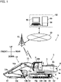
- FIG. 1 is a diagram depicting a configuration of a management system 5 of the hydraulic excavator 1.
- the management system 5 includes the hydraulic excavator 1 that performs work on a work site and a management server 53 installed in a management center 52.
- the management center 52 is, for example, installed in facilities such as a headquarters, a branch office, or a factory of a manufacturer (maker) of the hydraulic excavator 1, a rental company of the hydraulic excavator 1, a data center specializing in management of servers, facilities of an owner owning the hydraulic excavator 1, or the like.
- the management server 53 is an external device that remotely manages (grasps and monitors) the state of the hydraulic excavator 1.
- the management system 5 is configured to be able to perform two-way communication between the hydraulic excavator 1 that performs work on the work site and the management server 53 installed at a location remote from the work site via a communication line 50 of a wide area network. That is, the hydraulic excavator 1 and the management server 53 can transmit and receive information (data) via the communication line 50.
- the communication line 50 is a mobile telephone communication network (mobile communication network) operated by a mobile telephone operator or the like, the Internet, or the like.
- the wireless base station 51 transmits the received information to the management server 53 via the Internet.
- the management server 53 receives machine body information such as operation information, warning information, and recording information received from the hydraulic excavator 1, and stores the machine body information in a storage device 54 such as a hard disk drive.
- the management server 53 causes a display device 55 such as a liquid crystal display device to display the information stored in the storage device 54 thereon.
- a manager can grasp the state of the hydraulic excavator 1 by operating the management server 53 and displaying the information on the predetermined hydraulic excavator 1 on the display device 55.
- the management server 53 stores video data transmitted from the hydraulic excavator 1 in the storage device 54, and displays a video of the surroundings of the hydraulic excavator 1 (a synthetic video 199 depicted in FIG. 7 ) on a display screen of the display device 55 on the basis of the stored video data.
- the hydraulic excavator 1 includes a machine body (vehicle body) 4 and a work device 10 attached to the machine body 4.
- the machine body 4 includes a track structure 2 and a swing structure 3 provided so as to be swingable on the track structure 2.
- the work device 10 is attached to a front portion of the swing structure 3.
- the track structure 2 includes a left side travelling hydraulic motor 2al for driving a crawler on a left side and a right side travelling hydraulic motor 2ar (see FIG. 3 ) for driving a crawler on a right side.
- the track structure 2 travels by driving the pair of left and right crawlers by the travelling hydraulic motors 2al and 2ar.
- the swing structure 3 swings by driving a swing hydraulic motor 3a.
- the swing structure 3 includes: a swing frame 8; a cab 7 provided on the left side of a front portion of the swing frame 8; a counterweight 9 provided to a rear portion of the swing frame 8; and an engine compartment 6 provided on the rear side of the cab 7 in the swing frame 8.
- the engine compartment 6 houses an engine 21 as a prime mover and a hydraulic instrument such as a hydraulic pump driven by the engine 21.
- the work device 10 is rotatably connected to a center of the front portion of the swing frame 8.
- the engine 21 is a power source of the hydraulic excavator 1.
- the engine 21 is, for example, constituted by an internal combustion engine such as a diesel engine.
- the work device 10 is an articulated work device including a plurality of front implement members rotatably connected to each other and a plurality of hydraulic cylinders (actuators) for driving the front implement members.
- a boom 11, an arm 12, and a bucket 13 as three front implement members are connected in series with each other.
- a proximal end portion of the boom 11 is rotatably connected in the front portion of the swing frame 8 by a boom pin 11b.
- a proximal end portion of the arm 12 is rotatably connected in a distal end portion of the boom 11 by an arm pin 12b.
- the bucket 13 is rotatably connected in a distal end portion of the arm 12 by a bucket pin 13b.
- the boom 11 is driven by a hydraulic cylinder (hereinafter described also as a boom cylinder 11a), and is rotated with respect to the swing frame 8.
- the arm 12 is driven by a hydraulic cylinder (hereinafter described also as an arm cylinder 12a), and is rotated with respect to the boom 11.
- the bucket 13 is driven by a hydraulic cylinder (hereinafter described also as a bucket cylinder 13a), and is rotated with respect to the arm 12.
- the boom cylinder 11a has one end side thereof connected to the boom 11, and has another end side thereof connected to the swing frame 8.
- the arm cylinder 12a has one end side thereof connected to the arm 12, and has another end side thereof connected to the boom 11.
- the bucket cylinder 13a has one end side thereof connected to the bucket 13 via a link member, and has another end side thereof connected to the arm 12. Work such as excavation or leveling of natural ground is performed by driving each hydraulic cylinder of the work device 10.
- a controller 100 that controls various parts of the hydraulic excavator 1; a video data recording device 130 that records a video photographed by a plurality of photographing devices 30 (see FIG. 3 ) together with machine body information; and a battery 28 as a power supply device that supplies electric power to instruments mounted in the hydraulic excavator 1.
- FIG. 2 is a schematic diagram of the inside of the cab 7 as viewed toward the front from the rear side of a cab seat 75.
- the cab seat 75 on which an operator is to be seated; control levers (B1 to B4) for operating various parts of the hydraulic excavator 1; and a display device 190 that displays a predetermined display image on a display screen 191a.
- the display device 190 is attached to a pillar 74 on the right side as viewed from the cab seat 75 side.
- the display device 190 is, for example, a touch panel monitor functioning as an input unit and a display unit.
- the display device 190 displays a synthetic video 199 (see FIG.
- a right control lever B1 for operating the bucket 13 and operating the boom 11 is provided on the right side of the cab seat 75.
- a left control lever B2 for operating the swing structure 3 and operating the arm 12 is provided on the left side of the cab seat 75.
- a pair of left and right travelling levers are provided on the front side of the cab seat 75.
- the left travelling lever B4 is a control lever for operating the crawler on the left side.
- the right travelling lever B3 is a control lever for operating the crawler on the right side.
- a lock lever 79a is provided on the left side (door side) of the left side control lever B2.
- the lock lever 79a is a member that can be selectively operated between a lock position (raised position) at which the entering or exiting of the cab 7 is allowed and a lock release position (lowered position) at which the entering or exiting of the cab 7 is prohibited.
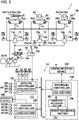
- FIG. 3 is a diagram depicting a main configuration of the hydraulic excavator 1.
- FIG. 3 depicts a hydraulic system 80 and a surrounding monitoring system 19 mounted in the hydraulic excavator 1.
- the boom cylinder 11a, the arm cylinder 12a, and the bucket cylinder 13a will be collectively described as a hydraulic cylinder 10a
- the left side travelling hydraulic motor 2al and the right side travelling hydraulic motor 2ar will be collectively described as a travelling hydraulic motor 2a.
- the hydraulic system 80 is provided with a plurality of hydraulic cylinders 10a (11a, 12a, and 13a).
- FIG. 3 representatively illustrates one hydraulic cylinder 10a.
- the hydraulic system 80 is provided with a pair of travelling hydraulic motors 2a.
- FIG. 3 representatively illustrates one travelling hydraulic motor 2a.
- the hydraulic system 80 includes: a main pump 25 as a variable displacement hydraulic pump driven by the engine 21; a pilot pump 26 as a fixed displacement hydraulic pump driven by the engine 21; a plurality of hydraulic actuators (the hydraulic cylinder 10a, the swing hydraulic motor 3a, and the travelling hydraulic motor 2a) driven by hydraulic operating fluid (hydraulic fluid) as working fluid delivered from the main pump 25; and control valves 81, 82, and 83 that respectively control flows of the hydraulic operating fluid supplied from the main pump 25 to the respective hydraulic actuators.
- a main pump 25 as a variable displacement hydraulic pump driven by the engine 21
- a pilot pump 26 as a fixed displacement hydraulic pump driven by the engine 21
- hydraulic actuators the hydraulic cylinder 10a, the swing hydraulic motor 3a, and the travelling hydraulic motor 2a
- hydraulic operating fluid hydraulic operating fluid
- the hydraulic operating fluid delivered from the pilot pump 26 is supplied to operation devices (a work operation device 71, a swing operation device 72, and a travelling operation device 73) used to operate the actuators.
- the work operation device 71 is an actuator operation device that commands operation of the hydraulic cylinder 10a of the work device 10.
- the work operation device 71 includes a control lever (corresponding to the right control lever B1 and the left control lever B2 in FIG. 2 ) 71a tilted by an operator and a pair of pressure reducing valves 71b of a hydraulic pilot type.
- the swing operation device 72 is an actuator operation device that commands operation of the swing hydraulic motor 3a.
- the swing operation device 72 includes a control lever (corresponding to the left control lever B2 in FIG.
- the travelling operation device 73 is an actuator operation device that commands operation of the travelling hydraulic motor 2a.
- the travelling operation device 73 includes a control lever (corresponding to the right travelling lever B3 and the left travelling lever B4 in FIG. 2 ) 73a tilted by the operator and a pair of pressure reducing valves 73b of a hydraulic pilot type.
- the pressure reducing valves 71b, 72b, and 73b of the actuator operation devices 71, 72, and 73 generate pilot pressures (which may be referred to as operation pressures) corresponding to operation amounts and operation directions of the control levers 71a, 72a, and 73a with the delivery pressure of the pilot pump 26 as a source pressure.
- the thus generated pilot pressures are introduced into pressure receiving chambers 81a, 81b, 82a, 82b, 83a, and 83b of the control valves 81, 82, and 83 corresponding to the hydraulic actuators (10a, 3a, and 2a), and are used as commands (signals) for operating the actuators by driving the control valves 81, 82, and 83.
- the hydraulic operating fluid delivered from the main pump 25 is supplied to the hydraulic actuators (the hydraulic cylinder 10a, the swing hydraulic motor 3a, and the travelling hydraulic motor 2a) through the control valves 81, 82, and 83 to drive the work device 10, the swing structure 3, and the track structure 2, respectively.
- the hydraulic excavator 1 includes a plurality of actuator operation sensors 70 as operation sensors that sense operations of the plurality of actuator operation devices 71, 72, and 73.
- the plurality of actuator operation sensors 70 include work operation sensors 76a and 76b, swing operation sensors 77a and 77b, and travelling operation sensors 78a and 78b.
- the actuator operation sensors 76a, 76b, 77a, 77b, 78a, and 78b are pressure sensors provided to pilot lines that connect the actuator operation devices 71, 72, and 73 to the pressure receiving chambers 81a, 81b, 82a, 82b, 83a, and 83b of the control valves 81, 82, and 83.
- the actuator operation sensors 76a, 76b, 77a, 77b, 78a, and 78b sense operation pressures (operation amounts) generated by operation of the control levers 71a, 72a, and 73a by the operator. That is, the work operation sensors 76a and 76b sense an operation for operating the work device 10 (hydraulic cylinder 10a), the swing operation sensors 77a and 77b sense an operation for operating (swinging) the swing structure 3, and the travelling operation sensors 78a and 78b sense an operation for operating (travelling) the track structure 2.
- the actuator operation sensors 76a, 76b, 77a, 77b, 78a, and 78b are connected to a machine controller 110 of the controller 100, and output information about the sensed operation amounts to the machine controller 110.
- a shut-off valve 89 is a solenoid selector valve that is provided to a pilot line connecting the pilot pump 26 to the pressure reducing valves 71b, 72b, and 73b of the actuator operation devices 71, 72, and 73, and is switchable between a communication position at which the supply of a pilot pressure from the pilot pump 26 to the pressure reducing valves 71b, 72b, and 73b is allowed and an interruption position at which the supply of the pilot pressure from the pilot pump 26 to the pressure reducing valves 71b, 72b, and 73b is prohibited.
- the shut-off valve 89 is operated by a lock lever device 79.
- the lock lever device 79 is an operation device used to operate the actuators.
- the lock lever device 79 includes: a lock lever 79a to be selectively operated between a lock position (raised position) at which the entering or exiting of the cab 7 is allowed and operation of the actuators (10a, 3a, and 2a) by the actuator operation devices 71, 72, and 73 is disabled and a lock release position (lowered position) at which the entering or exiting of the cab 7 is prohibited and operation of the actuators (10a, 3a, and 2a) by the actuator operation devices 71, 72, and 73 is enabled; a shut-off relay 79c for supplying or interrupting electric power from the battery 28; and a lock lever operation sensor 79b as an operation sensor that senses an operation of the lock lever 79a of the lock lever device 79.
- shut-off relay 79c When the lock lever 79a is operated to the lock release position, the shut-off relay 79c is turned on, that is, the shut-off relay 79c is set in a closed state, so that electric power is supplied from the battery 28 to the shut-off valve 89.
- the solenoid When electric power is supplied to the shut-off valve 89, the solenoid is excited, and the shut-off valve 89 is switched to the communication position.
- command pilot pressures corresponding to operation amounts of the control levers 71a, 72a, and 73a are generated by the pressure reducing valves 71b, 72b, and 73b, and the hydraulic actuators (10a, 3a, and 2a) corresponding to the operated control levers 71a, 72a, and 73a operate.
- the shut-off relay 79c When the lock lever 79a is operated to the lock position, the shut-off relay 79c is turned off, that is, the shut-off relay 79c is set in an opened state, so that the supply of electric power from the battery 28 to the shut-off valve 89 is interrupted.
- the solenoid When the supply of electric power to the shut-off valve 89 is interrupted, the solenoid is demagnetized, and the shut-off valve 89 is switched to the interruption position.
- the pilot source pressure to the pressure reducing valves 71b, 72b, and 73b is interrupted, and operation using the control levers 71a, 72a, and 73a is disabled.
- the lock lever operation sensor 79b senses an operation position of the lock lever 79a, and outputs a signal indicating a result of the sensing to the machine controller 110 of the controller 100.
- the surrounding monitoring system 19 is a system for monitoring the surroundings of the machine body 4.
- the surrounding monitoring system 19 includes: the plurality of photographing devices 30 that photograph the surroundings of the machine body 4; the display device 190 that displays a video photographed by the photographing devices 30 on the display screen 191a; the video data recording device 130 that records video data including the video photographed by the photographing devices 30; the controller 100 that controls the display device 190 and the video data recording device 130; a plurality of object sensors 90 that sense an object in the surroundings of the machine body 4; and a communication device 160 for performing wireless communication with the management server 53 as an external device installed on the outside of the hydraulic excavator 1.
- the display device 190 functions also as a notifying device that displays information regarding presence of an object on the display screen 191a when the object is present in the surroundings of the hydraulic excavator 1, and which notifies the operator of the hydraulic excavator 1 of sensing of the object.
- the communication device 160 is a wireless communication device capable of wireless communication with the wireless base station 51 connected to the communication line 50 as a wide area network.
- the communication device 160 has a communication interface including a communication antenna having a band such, for example, as a 2.1-GHz band as a reception band.
- the communication device 160 transmits and receives information to and from the management server 53 and the like via the wireless base station 51 and the communication line 50.
- the controller 100 includes: the machine controller 110 that controls various parts of the hydraulic excavator 1 in a centralized manner; and the monitor controller 120 that displays information (data) regarding the operation state of the hydraulic excavator 1 and the video photographed by the photographing devices 30 on the display screen 191a of the display device 190.
- the machine controller 110 controls the valves, pumps, and the like of the hydraulic system 80 on the basis of posture information of the hydraulic excavator 1, operation information, information about loads on the actuators, and the like.
- the monitor controller 120 generates a synthetic video 199 by synthesizing the video photographed by the plurality of photographing devices 30 and an image generated on the basis of a result of sensing in the object sensors 90, and displays the generated synthetic video 199 on the display screen 191a of the display device 190 (see FIG. 7 ).
- the monitor controller 120 transmits data of the generated synthetic video 199 (which will hereinafter be described also as synthetic video data) to the video data recording device 130.
- the video data recording device 130 includes a recording controller 140, a constant recording section 151 as a recording device, and an event recording section 152 as a recording device.
- the constant recording section 151 is a volatile memory or a nonvolatile memory
- the event recording section 152 is a nonvolatile memory provided separately from the constant recording section 151.
- the recording controller 140 constantly records the synthetic video data generated by the monitor controller 120 in the constant recording section 151. When the recording controller 140 receives a recording trigger signal from the machine controller 110, the recording controller 140 records and retains the synthetic video data recorded in the constant recording section 151.
- the machine controller 110 determines whether or not a recording and retaining condition is satisfied on the basis of a result of sensing in the object sensors 90 and a result of sensing in the operation sensors (the lock lever operation sensor 79b and the actuator operation sensors 70). When the recording and retaining condition is satisfied, the machine controller 110 transmits the recording trigger signal to the video data recording device 130, and thereby makes the video data recording device 130 record and retain the synthetic video data.
- the recording controller 140 transmits the recorded and retained synthetic video data to the management server 53 (see FIG. 1 ) by wireless communication by use of the communication device 160.
- the management server 53 stores the received synthetic video data in the storage device 54 (see FIG. 1 ).
- the machine controller 110, the monitor controller 120, and the recording controller 140 are constituted by microcomputers including CPUs (Central Processing Units) 111, 121, and 141 as operation circuits, ROMs (Read Only Memories) 112, 122, and 142 as storage devices, RAMs (Random Access Memories) 113, 123, and 143 as storage devices, input-output interfaces (I/O interfaces), and other peripheral circuits.
- CPUs Central Processing Units
- ROMs Read Only Memories
- RAMs Random Access Memories
- I/O interfaces input-output interfaces
- Each of the controllers 110, 120, and 140 may be constituted by one microcomputer, or may be constituted by a plurality of microcomputers.
- the ROMS 112, 122, and 142 of the respective controllers 110 are a nonvolatile memory such as an EEPROM.
- the ROMS 112, 122, and 142 store a program capable of performing various kinds of computation. That is, the ROMS 112, 122, and 142 of the respective controllers 110, 120, and 140 are storage media from which a program that implements functions of the present embodiment is readable.
- the RAMs 113, 123, and 143 are a volatile memory, and are a work memory between which and the CPUs 111, 121, and 141 data is directly input and output.
- the RAMs 113, 123, and 143 temporarily store necessary data while the CPUs 111, 121, and 141 execute the programs by computation.
- each of the controllers 110, 120, and 140 may further include a storage device such as a flash memory or a hard disk drive.
- the CPUs 111, 121, and 141 are processing devices that expand control programs stored in the ROMS 112, 122, and 142 into the RAMs 113, 123, and 143 and execute the control programs by computation.
- the CPUs 111, 121, and 141 perform predetermined computation processing on signals captured from the input-output interfaces, the ROMS 112, 122, and 142, and the RAMs 113, 123, and 143 according to the control programs.
- Signals from various kinds of devices are input to the input-output interfaces.
- the input-output interfaces convert the input signals such that the signals can be subjected to computation by the CPUs 111, 121, and 141.
- the input-output interfaces generate signals for output according to results of computation in the CPUs 111, 121, and 141, and output the signals to various kinds of devices.
- the controllers 110, 120, and 140 are connected to each other via a vehicle-mounted network 22 referred to as a CAN (Controller Area Network). Hence, the controllers 110, 120, and 140 can mutually transmit and receive information.
- a vehicle-mounted network 22 referred to as a CAN (Controller Area Network).
- FIG. 4 is a plan schematic view of the hydraulic excavator 1.
- FIG. 4 depicts photographing ranges of the plurality of photographing devices 30.
- the plurality of photographing devices 30 are attached to the swing structure 3.
- the plurality of photographing devices 30 include a left camera 31 that photographs in a left direction of the swing structure 3, a right camera 32 that photographs in a right direction of the swing structure 3, a front camera 33 that photographs in a forward direction of the swing structure 3, and a rear camera 34 that photographs in a rearward direction of the swing structure 3.
- Each of the photographing devices 30 is, for example, a wide-angle video camera including a CCD, CMOS, or another imaging element excellent in durability and weatherability and a wide-angle lens.
- the left camera 31 is a photographing device that continuously photographs a region on the left side of the swing structure 3 in such a direction as to obliquely look down on the region with a left-right angle of view of approximately 180°.
- the right camera 32 is a photographing device that continuously photographs a region on the right side of the swing structure 3 in such a direction as to obliquely look down on the region with a left-right angle of view of approximately 180°.
- the front camera 33 is a photographing device that continuously photographs a region in front of the swing structure 3 in such a direction as to obliquely look down on the region with a left-right angle of view of approximately 180°.
- the rear camera 34 is a photographing device that continuously photographs a region in the rear of the swing structure 3 in such a direction as to obliquely look down on the region with a left-right angle of view of approximately 180°.
- the front camera 33 is attached below the boom 11 of the work device 10 to a position not interfering with the work device 10.
- rectangular areas (A1, A2, A3, and A4) in the surroundings of the hydraulic excavator 1 represent regions that can be photographed by the respective cameras 31, 32, 33, and 34.
- Each of the photographing regions A1, A2, A3, and A4 is photographed so as to overlap adjacent areas in parts at both end portions in the longitudinal direction of the photographing region.
- the photographing regions A1, A2, A3, and A4 are set so as to include a caution zone S2 to be described later.
- the plurality of object sensors 90 are attached to the swing structure 3.
- the plurality of object sensors 90 include a left object sensor 91 that senses an object present in the left direction of the swing structure 3, a right object sensor 92 that senses an object present in the right direction of the swing structure 3, a front object sensor 93 that senses an object present in the forward direction of the swing structure 3, and a rear object sensor 94 that senses an object present in the rearward direction of the swing structure 3.
- the left object sensor 91 is attached in the vicinity of the left camera 31, and monitors the region on the left side of the swing structure 3.
- a monitoring region of the left object sensor 91 is substantially the same as the photographing region A1 of the left camera 31.
- the right object sensor 92 is attached in the vicinity of the right camera 32, and monitors the region on the right side of the swing structure 3.
- a monitoring region of the right object sensor 92 is substantially the same as the photographing region A2 of the right camera 32.
- the front object sensor 93 is attached in the vicinity of the front camera 33, and monitors the region on the front side of the swing structure 3.
- a monitoring region of the front object sensor 93 is substantially the same as the photographing region A3 of the front camera 33.
- the rear object sensor 94 is attached in the vicinity of the rear camera 34, and monitors the region on the rear side of the swing structure 3.
- the object sensors 90 each include a plurality of infrared sensors arranged in a matrix form in a vertical and a horizontal direction.
- the infrared sensors are a ToF (Time of Flight) sensor that measures a distance to an object from a time difference from the application of an infrared ray to the reflection of the infrared ray, and outputs a distance measurement result to the machine controller 110.
- the infrared sensor outputs a signal indicating the reflection intensity of the infrared ray reflected from the object to the machine controller 110.
- FIG. 5 is a functional block diagram depicting main functions of the surrounding monitoring system 19. Incidentally, while the plurality of object sensors 90, the plurality of actuator operation sensors 70, and the plurality of photographing devices 30 are provided, only one object sensor 90, one actuator operation sensor 70, and one photographing device 30 are depicted representatively. As depicted in FIG. 5 , the machine controller 110 functions as a warning zone setting section 114, an object identifying section 115, and a condition determining section 116 by executing a program stored in the ROM 112.
- the object identifying section 115 determines whether or not an object is present in the surroundings of the hydraulic excavator 1 on the basis of sensing information from the plurality of object sensors 90. When determining that an object is present in the surroundings of the hydraulic excavator 1, the object identifying section 115 identifies the position of the object in an excavator reference coordinate system on the basis of results of sensing in the object sensors 90 and information such as the position coordinates of the object sensors 90 in the excavator reference coordinate system and the attachment angles of the object sensors 90, the information being stored in the ROM 112.
- the object identifying section 115 determines whether or not the object sensed by the object sensors 90 is a human on the basis of the results of sensing in the object sensors 90. The object identifying section 115 determines that the object is a human when the reflection intensity of the infrared ray reflected from the object is within a predetermined range. The object identifying section 115 determines that the object is not a human when the reflection intensity of the infrared ray reflected from the object is outside the predetermined range.
- the above-described predetermined range is, for example, preset on the basis of the reflection intensity when the infrared ray is reflected by a reflective vest worn by a worker, the reflection intensity when the infrared ray is reflected by the skin of a human, or the like.
- the predetermined range of the reflection intensity for human determination is stored in the ROM 112.
- the condition determining section 116 determines whether or not the object sensed by the object sensors 90 is present within a warning zone S1 on the basis of the position of the object with respect to the excavator which is identified by the object identifying section 115 and information regarding the warning zone S1 set by the warning zone setting section 114. In addition, the condition determining section 116 determines whether or not the object sensed by the object sensors 90 is present within the caution zone S2 on the basis of the position of the object with respect to the excavator which is identified by the object identifying section 115 and information regarding the caution zone S2 stored in a caution zone storage section 117.
- the condition determining section 116 determines whether or not operation of the actuator by the actuator operation device 71, 72, or 73 is performed on the basis of a result of sensing in the actuator operation sensor 70.
- the condition determining section 116 determines that the actuator operation device 71, 72, or 73 is operated when a pilot pressure P sensed by the actuator operation sensor (pressure sensor) 70 is equal to or more than a threshold value P0.
- the condition determining section 116 determines that the actuator operation device 71, 72, or 73 is not operated when the pilot pressure P is less than the threshold value P0.
- the threshold value P0 is a threshold value for determining whether or not the actuator operation device 71, 72, or 73 is operated, and the threshold value P0 is stored in the ROM 112 of the machine controller 110 in advance.
- the threshold value P0 is a value larger than the minimum value Pmin and smaller than the maximum value Pmax (Pmin ⁇ P0 ⁇ Pmax).
- the condition determining section 116 determines whether the lock lever device 79 is operated to the lock release position or operated to the lock position on the basis of a result of sensing in the lock lever operation sensor 79b.
- the condition determining section 116 determines whether or not predetermined storing and retaining conditions are satisfied.
- the condition determining section 116 transmits a recording trigger signal to the video data recording device 130 when a first to a third storing and retaining condition are satisfied.
- the first storing and retaining condition is satisfied when all of first to fourth conditions in the following are satisfied.
- the first storing and retaining condition is not satisfied when any one of the first to fourth conditions is not satisfied.
- the second storing and retaining condition is satisfied when all of the first condition, the second condition, the fourth condition, and a fifth condition in the following are satisfied.
- the second storing and retaining condition is not satisfied when any one of the first condition, the second condition, the fourth condition, and the fifth condition is not satisfied.
- Fifth condition operation using at least one of the actuator operation devices 71, 72, and 73 is performed
- the third storing and retaining condition is satisfied when all of the first to third conditions, the fifth condition, and a sixth condition in the following are satisfied.
- the third storing and retaining condition is not satisfied when any one of the first to third conditions, the fifth condition, and the sixth condition is not satisfied.
- Sixth condition the object is not present in the warning zone S1 but is present within a caution zone (second range) S2 preset so as to include the warning zone S1.
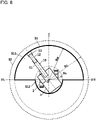
- FIG. 6 is a diagram of the hydraulic excavator 1 as viewed from above.
- FIG. 6 depicts the warning zone S1 and the caution zone S2 of the hydraulic excavator 1.
- the caution zone S2 is a circular range of a maximum swing radius Rx of the hydraulic excavator 1.
- the maximum swing radius Rx corresponds to a length from a swing central axis O of the swing structure 3 to a distal end of the bucket 13 when the work device 10 is extended most toward the front (in a direction orthogonal to the swing central axis).
- the maximum swing radius Rx corresponds to a maximum length from the swing central axis O to a position reached by the work device 10 in the direction orthogonal to the swing central axis O.
- the caution zone S2 is the circular range of the maximum swing radius Rx in the present embodiment, a circular range of a radius obtained by adding an allowance value (margin) to the maximum swing radius Rx may be set as the caution zone S2.
- the caution zone S2 is determined in advance on the basis of dimensions of various parts of the hydraulic excavator 1, and is stored in the caution zone storage section 117 of the ROM 112.
- the warning zone S1 is a range set so as to be included in the caution zone S2.
- the warning zone S1 is preset in peripheral regions in the vicinity of the machine body 4, that is, a region within the swing range of the machine body 4 and a region close to the machine body 4 including the swing trajectories of the boom 11, the arm 12, and the bucket 13.
- the warning zone S1 is set in order to prevent contact between the object present within the range of the warning zone S1 and the hydraulic excavator 1 when swing operation of the swing structure 3 and travelling operation of the track structure 2 are performed.
- the warning zone setting section 114 sets the warning zone S1 on the basis of the posture information of the hydraulic excavator 1 which is sensed by a posture sensor 60.
- the posture sensor 60 includes: a boom angle sensor 61 that senses the angle of the boom 11 (boom angle) with respect to the swing structure 3; an arm angle sensor 62 that senses the angle of the arm 12 (arm angle) with respect to the boom 11; a bucket angle sensor 63 that senses the angle of the bucket 13 (bucket angle) with respect to the arm 12; and a swing angle sensor 64 that senses the angle of the swing structure 3 (swing angle) with respect to the track structure 2.
- the boom angle sensor 61, the arm angle sensor 62, the bucket angle sensor 63, and the swing angle sensor 64 are, for example, a potentiometer that outputs a signal (voltage) corresponding to the angle obtained.
- the ROM 112 store a left set angle ⁇ L, a right set angle ⁇ R, and dimension data of various parts of the work device 10.
- a left set angle ⁇ L a right set angle ⁇ R
- dimension data of various parts of the work device 10.
- an x-axis extending in the forward-rearward direction of the track structure 2 is set as a reference (zero degrees)
- a left swing direction is set as a negative direction
- a right swing direction is set as a positive direction
- the left set angle ⁇ L is set at -90 degrees
- the right set angle ⁇ R is set at +90 degrees.
- the warning zone setting section 114 computes, as a work radius Rw, a length obtained by adding a predetermined length as an allowance value (margin) to the length from the swing central axis O to the distal end of the bucket 13 on the basis of the posture information sensed by the posture sensor 60 (the boom angle, the arm angle, and the bucket angle) and the dimension data of the various parts of the work device 10 (a length from the boom pin 11b to the arm pin 12b, a length from the arm pin 12b to the bucket pin 13b, and a length from the bucket pin 13b to the distal end of the bucket).
- a predetermined length as an allowance value
- the warning zone setting section 114 sets, as the warning zone S1, a region obtained by synthesizing a sectorial (semicircular) region S11 in front of the swing structure 3 which is defined by the left set angle ⁇ L, the right set angle ⁇ R, and the work radius Rw and a circular region (that is, the swing range of the machine body 4) S12 having a distance from the swing central axis O to an outermost peripheral portion of the swing structure 3 (rear portion of the swing structure 3) as a radius Rs.
- the monitor controller 120 functions as a bird's-eye video generating section 124 and a synthetic video generating section 125 by executing a program stored in the ROM 122.
- the bird's-eye video generating section 124 obtains images photographed by the left camera 31, the right camera 32, the front camera 33, and the rear camera 34, and generates a bird's-eye video on the basis of the obtained images.
- the bird's-eye video generating section 124 performs lens distortion correction on the obtained images, and further performs processing of viewpoint conversion into an upward viewpoint image.
- the bird's-eye video generating section 124 synthesizes the image obtained by performing the viewpoint conversion processing and an illustration image (or a photographed image) of the hydraulic excavator 1 as viewed from above, and thereby generates a bird's-eye video 194a as depicted in FIG. 7 .
- the illustration image (or the photographed image) of the hydraulic excavator 1 as viewed from above is stored in the ROM 122 in advance.
- FIG. 7 is a diagram depicting an example of the synthetic video 199 displayed on the display screen 191a of the display device 190.
- the synthetic video generating section 125 synthesizes rectangular frame images 195b, 196b, and 197b enclosing objects 195a, 196a, and 197a identified by the object identifying section 115 with the bird's-eye video 194a generated by the bird's-eye video generating section 124, and displays the synthesized bird's-eye video 194a in a camera image region 194.
- the synthetic video generating section 125 displays, in different colors, the frame image 197b enclosing the object determined to be a human in the object identifying section 115 and the frame images 195b and 196b enclosing the objects determined not to be a human in the object identifying section 115. For example, suppose that the frame image 197b is red, and that the frame images 195b and 196b are yellow.
- an icon region 192 displaying a predetermined icon and a message region 193 displaying a predetermined message are formed above the camera image region 194 displaying the bird's-eye video 194a as depicted in the figure.
- the synthetic video generating section 125 displays a warning message image for notifying the operator of the satisfaction of the recording and retaining condition or the like and calling attention in the message region 193.
- the warning message image is, for example, a message image preset for each condition satisfied, such as a message image notifying that a human (or an object other than a human) is present within the warning zone S1.
- These message images are stored in the ROM 122, selected according to the satisfied condition, and displayed in the message region 193.
- the synthetic video generating section 125 displays an icon image corresponding to the satisfied condition in the icon region 192.
- the synthetic video generating section 125 may display a warning message image for notifying the operator to the effect that operation is limited in the message region 193.
- the synthetic video generating section 125 may display an icon image for notifying the operator to the effect that operation is limited in the icon region 192.
- the synthetic video generating section 125 may display a warning message image for notifying the operator that an abnormality in the surrounding monitoring system 19 is detected in the message region 193.
- the synthetic video generating section 125 may display an icon image for notifying the operator that an abnormality in the surrounding monitoring system 19 is detected in the icon region 192.
- the monitor controller 120 displays the synthetic video 199 obtained by synthesizing the video photographed by the photographing devices 30 and the image generated according to object sensing information (an image of a frame, a message, and an icon) on the display screen 191a of the display device 190.
- the recording controller 140 functions as a recording control section 144 by executing a program stored in the ROM 144.
- the recording control section 144 obtains the synthetic video data generated by the synthetic video generating section 125, and continuously records the obtained synthetic video data as overwritable data in the constant recording section 151.
- the recording control section 144 When the recording capacity of the constant recording section 151 reaches an upper limit, the recording control section 144 performs overwriting processing that sequentially deletes old synthetic video data recorded in the constant recording section 151, and rewrites new synthetic video data.
- the recording control section 144 receives a recording trigger signal, the recording control section 144 determines that an event has occurred, and records and retains the synthetic video data generated by the synthetic video generating section 125. Specifically, the recording control section 144 stores synthetic video data of a predetermined period including time T0 at which the recording trigger signal is received as event video data in the event recording section 152.
- FIG. 8 is a timing diagram of assistance in explaining contents of recording control processing by the recording control section 144.
- the synthetic video data is recorded with the passage of time t in the constant recording section 151.
- the synthetic video data of a period from a time (T0 - Ta) before time T0 to a time (T0 + Ta) after time T0 is stored as the event video data in the event recording section 152.
- Ta is approximately five minutes, for example.
- the time (2 ⁇ Ta) of the synthetic video data stored as the event video data can be set optionally.
- the storage time of the event video data before time T0 at which the recording trigger signal is received and the storage time of the event video data after time T0 at which the recording trigger signal is received may be different from each other.
- FIG. 9 there will be made a description of the contents of processing of determining whether a recording and retaining condition is satisfied, the processing being performed by the machine controller 110.
- the processing of a flowchart depicted in FIG. 9 is started by turning on an ignition switch (that is, turning a key on), for example. After an initial setting is made, processing of steps S110 to S165 is performed repeatedly.
- step S110 the machine controller 110 performs information obtainment processing, and proceeds to step S115.
- the machine controller 110 obtains a result of sensing in the lock lever operation sensor 79b (information regarding the operation position of the lock lever 79a), results of sensing in the object sensors 90 (information regarding an object present in the surroundings of the machine body 4), results of sensing in the actuator operation sensors 70 (actuator operation information), and a result of sensing in the posture sensor 60 (posture information of the work device 10).
- step S115 the machine controller 110 computes the work radius Rw on the basis of the result of sensing in the posture sensor 60 which is obtained in step S110. Further, the machine controller 110 sets the warning zone S1 on the basis of the work radius Rw, the left set angle ⁇ L, and the right set angle ⁇ R. The machine controller 110 then proceeds to step S120.
- step S120 the machine controller 110 determines whether or not the lock lever 79a is operated to the lock release position on the basis of the result of sensing in the lock lever operation sensor 79b which is obtained in step S110.
- the processing proceeds to step S125.
- the processing returns to step S110.
- step S125 the machine controller 110 determines whether or not an object is present in the surroundings of the machine body 4 on the basis of the results of sensing in the object sensors 90 which are obtained in step S110. When it is determined in step S125 that an object is present in the surroundings of the machine body 4, the processing proceeds to step S130. When it is determined in step S125 that no object is present in the surroundings of the machine body 4, the processing returns to step S110.
- step S130 the machine controller 110 computes the position of the sensed object with respect to the excavator on the basis of the results of sensing in the object sensors 90 which are obtained in step S110. The machine controller 110 then proceeds to step S135.
- step S135 the machine controller 110 determines whether or not the sensed object is a human on the basis of the results of sensing in the object sensors 90 which are obtained in step S110. When it is determined in step S135 that the sensed object is a human, the processing proceeds to step S137. When it is determined in step S135 that the sensed object is not a human, the processing proceeds to step S145.
- step S137 the machine controller 110 determines whether or not the sensed human is present within the caution zone S2 on the basis of a computation result in step S130. When it is determined in step S137 that the sensed human is present within the caution zone S2, the processing proceeds to step S140. When it is determined in step S137 that the sensed human is not present within the caution zone S2, the processing returns to step S110.
- step S140 the machine controller 110 determines whether or not the sensed human is present within the warning zone S1 on the basis of the computation result in step S130. When it is determined in step S140 that the sensed human is present within the warning zone S1, the processing proceeds to step S160. When it is determined in step S140 that the sensed human is not present within the warning zone S1, the processing proceeds to step S150.
- step S145 the machine controller 110 determines whether or not the sensed object is present within the warning zone S1 on the basis of the computation result in step S130. When it is determined in step S145 that the sensed object is present within the warning zone S1, the processing proceeds to step S150. When it is determined in step S145 that the sensed object is not present within the warning zone S1, the processing returns to step S110.
- step S150 the machine controller 110 determines whether or not actuator operation is performed on the basis of the results of sensing in the actuator operation sensors 70 which are obtained in step S110. When it is determined in step S150 that actuator operation is performed, the processing proceeds to step S160. When it is determined in step S150 that actuator operation is not performed, the processing returns to step S110.
- step S160 the machine controller 110 determines that a recording and retaining condition is satisfied, and transmits a recording trigger signal to the video data recording device 130. The machine controller 110 then proceeds to step S165. In step S165, the machine controller 110 performs standby processing of standing by until a predetermined time Ta passes. The machine controller 110 then ends the processing depicted in the flowchart of FIG. 9 .
- the machine controller 110 performs the processing of computing the position with respect to the excavator (S130), the human determination processing (S135), the processing of determining presence within the caution zone S2 (S137), and the processing of determining presence within the warning zone S1 (S140 and S145) for each object sensed, and determines whether or not a storing and retaining condition is satisfied for each object.
- the machine controller 110 transmits a recording trigger signal (S160) when any storing and retaining condition is satisfied as a result of determining whether the storing and retaining condition is satisfied for each object.
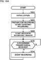
- FIG. 10A there will be made a description of contents of recording control processing performed by the recording controller 140.
- the processing of a flowchart depicted in FIG. 10A is started by turning on the ignition switch (that is, turning the key on), for example.
- step S210 the recording controller 140 performs initialization processing.
- the recording controller 140 then proceeds to step S215.
- step S215 the recording controller 140 performs recording preparation processing.
- the recording controller 140 starts constantly recording the synthetic video data generated by the monitor controller 120 in the constant recording section 151.
- the recording controller 140 determines that the recording preparation processing is completed when the predetermined time Ta has passed since a start time of the recording in the constant recording section 151.
- the recording controller 140 then proceeds to step S220.
- step S220 the recording controller 140 starts to receive a recording trigger signal from the machine controller 110.
- the recording controller 140 then proceeds to step S230.
- step S230 the recording controller 140 determines whether or not a recording trigger signal from the machine controller 110 is received. The recording controller 140 repeatedly performs this determination processing until determining that a recording trigger signal is received from the machine controller 110. When determining that a recording trigger signal from the machine controller 110 is received, the recording controller 140 proceeds to step S240.
- step S240 the recording controller 140 stores the synthetic video data of a predetermined period [time (T0 - Ta) to time (T0 + Ta)] including time T0 at which the recording trigger signal is received as event video data in the event recording section 152. The recording controller 140 then returns to step S230.
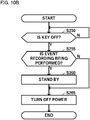
- FIG. 10B there will be made a description of contents of processing when the recording control of the recording controller 140 is ended.
- the processing of a flowchart depicted in FIG. 10B is started by performing the processing of starting to receive a recording trigger (step S220 in FIG. 10A ).
- step S250 the recording controller 140 determines whether or not the ignition switch is turned off (that is, the key is turned off). The recording controller 140 repeatedly performs this determination processing until determining that the ignition switch is turned off. When determining that the ignition switch is turned off, the recording controller 140 proceeds to step S255.
- step S255 the recording controller 140 determines whether or not event recording processing (step S240) is being performed. When it is determined in step S255 that the event recording processing is being performed, the processing proceeds to step S260. When it is determined in step S255 that the event recording processing is not being performed, the processing proceeds to step S265. In step S260, the recording controller 140 performs standby processing of standing by until the predetermined time Ta passes. The recording controller 140 then proceeds to step S265. In step S265, the recording controller 140 performs predetermined ending processing, turns off power, and ends the processing depicted in the flowchart of FIG. 10B .
- a recording and retaining condition is satisfied (Y in S120 in FIG. 9 ⁇ Y in S125 ⁇ S130 ⁇ Y in S135 ⁇ Y in S137 ⁇ N in S140 ⁇ Y in S150). Therefore, a recording trigger signal is transmitted from the controller 100 to the video data recording device 130 (S160 in FIG. 9 ), and the video data recording device 130 records and retains synthetic video data (Y in S230 in FIG. 10A ⁇ S240). That is, the present embodiment can record and retain the synthetic video data due to the actuator operation of the operator when there is a possibility that the hydraulic excavator 1 approaches the worker.
- a recording and retaining condition is satisfied even when the operator is not performing any actuator operation (Y in S120 in FIG. 9 ⁇ Y in S125 ⁇ S130 ⁇ Y in S135 ⁇ Y in S137 ⁇ Y in S140). Therefore, a recording trigger signal is transmitted from the controller 100 to the video data recording device 130 (S160 in FIG. 9 ), and the video data recording device 130 records and retains synthetic video data (Y in S230 in FIG. 10A ⁇ S240). That is, the present embodiment can record and retain the synthetic video data due to an actuator operation of the operator when the worker is present in the vicinity of the hydraulic excavator 1 and there is a possibility that the hydraulic excavator 1 comes into contact with the worker.
- a recording and retaining condition is satisfied (Y in S120 in FIG. 9 ⁇ Y in S125 ⁇ S130 ⁇ N in S135 ⁇ Y in S145 ⁇ Y in S150). Therefore, a recording trigger signal is transmitted from the controller 100 to the video data recording device 130 (S160 in FIG. 9 ), and the video data recording device 130 records and retains synthetic video data (Y in S230 in FIG. 10A ⁇ S240). That is, the present embodiment can record and retain the synthetic video data due to an actuator operation of the operator when there is a possibility that the hydraulic excavator 1 comes into contact with the work vehicle.
- the controller 100 may determine that a recording and retaining condition is satisfied and make the video data recording device 130 record and retain the video data when the lock lever device 79 is operated to the lock release position and when an object is present in the surroundings of the machine body 4. That is, steps S115, S130, S135, S137, S140, S145, and S150 depicted in the flowchart of FIG. 9 may be omitted. Operation of the actuators by the actuator operation devices 71, 72, and 73 is enabled when the lock lever device 79 is operated to the lock release position. According to this configuration, it is possible to record and retain the video data in a scene in which there is a possibility that the object and the hydraulic excavator 1 approach each other or come into contact with each other.
- the controller 100 may determine that a recording and retaining condition is satisfied and make the video data recording device 130 record and retain the video data when the lock lever device 79 is operated to the lock release position and when an object is present in the surroundings of the machine body 4 and when the object is a human. That is, steps S115, S130, S137, S140, S145, and S150 depicted in the flowchart of FIG. 9 may be omitted. Operation of an actuator(s) by at least one of the actuator operation devices 71, 72, and 73 is enabled when the lock lever device 79 is operated to the lock release position. According to this configuration, it is possible to record and retain the video data in a scene in which there is a possibility that the human and the hydraulic excavator 1 approach each other or come into contact with each other.
- the controller 100 may determine that a recording and retaining condition is satisfied and make the video data recording device 130 record and retain the video data when operation using at least one of the actuator operation devices 71, 72, and 73 is performed and when an object is present in the surroundings of the machine body 4. That is, step S115 and steps S130 to S145 depicted in the flowchart of FIG. 9 may be omitted, and the processing of step S150 may be performed in place of the processing of step S120. According to this configuration, it is possible to record and retain the video data in a scene in which there is a possibility that the object and the hydraulic excavator 1 approach each other or come into contact with each other.
- the controller 100 may make the video data recording device 130 record and retain the video data when a recording and retaining condition is satisfied, the recording and retaining condition including a condition that the lock lever device 79 is operated to the lock release position, a condition that an object is present in the surroundings of the machine body 4, and a condition that rotational speed (engine speed) of the engine 21 is changed.
- the controller 100 determines whether or not the engine speed is changed on the basis of a signal from an engine speed sensor that senses the engine speed. According to such a modification, when the operator starts work by operating the actuator operation devices 71, 72, and 73, and the engine speed is changed, the recording and retaining of the video data is started. It is therefore possible to record and retain the video data in a scene in which there is a possibility that the object and the hydraulic excavator 1 approach each other or come into contact with each other.
- the left set angle ⁇ L defining the caution zone S2 is 90 degrees in the left swing direction with respect to the x-axis and the right set angle ⁇ R defining the caution zone S2 is 90 degrees in the right swing direction with respect to the x-axis.
- the left set angle ⁇ L and the right set angle ⁇ R can be set at freely selected values.
- the left set angle ⁇ L and the right set angle ⁇ R may be allowed to be set optionally by the operator of the hydraulic excavator 1 by performing a predetermined operation on the display device (touch panel monitor) 190.
- a region obtained by synthesizing the sectorial (semicircular) region S11 defined by the left set angle ⁇ E, the right set angle ⁇ R, and the work radius Rw and the circular region S12 of the radius Rs which has the swing central axis O as a center thereof is set as the warning zone (first range) S1.
- the present invention is not limited to this.
- a polygonal warning zone (first range) S1 having touch-operated positions as vertices thereof may be set by touch-operating a plurality of positions on the display screen of the display device (touch panel monitor) 190.
- the synthetic video data is recorded and retained and transmitted to the management server 53.
- the present invention is not limited to this.
- the data of the video photographed by the photographing devices 30 may be recorded and retained as it is and transmitted to the management server 53.
- the monitor controller 120 may display the video photographed by the plurality of photographing devices 30 as individual videos on the display screen 191a of the display device 190.
- the actuator operation sensors 70 may be potentiometers or the like that sense operation angles (operation amounts) of the control levers 71a, 72a, and 73a.
- the controller 100 determines that operation using the actuator operation devices 71, 72, and 73 is performed when the absolute values
- the operation angles of the control levers 71a, 72a, and 73a in a neutral position are 0 (zero) degrees, and a value larger than 0 (zero) is set as the threshold value ⁇ 0.
- the machine controller 110 determines whether or not an object is a human on the basis of reflection intensity information transmitted from the object sensors 90.
- a determining method is not limited to this.
- the object sensors 90 may determine whether or not the object is a human on the basis of the reflection intensity information, and output a result of the determination to the machine controller 110.
- the machine controller 110 determines whether or not the object is a human on the basis of the determination result (for example, a determination flag signal) transmitted from the object sensors 90.
- the object sensors 90 are infrared sensors.
- the object sensors 90 may be stereo cameras.
- the stereo cameras function as the object sensors 90 and the photographing devices 30.
- the controller 100 extracts a shape pattern of an object photographed by the stereo cameras.
- the controller 100 determines that the object is a human when the extracted pattern matches a preset human pattern.
- the controller 100 determines that the object is not a human when the extracted pattern does not match the preset human pattern.
- three-dimensional LiDAR may be adopted for the object sensors 90.
- recording and retaining processing is ended when the predetermined time Ta passes from time T0 at which a recording trigger signal is received.
- the recording and retaining processing may be ended when the recording and retaining condition ceases to be satisfied, for example, when the lock lever 79a is operated to the lock position or when the object sensors 90 cease to sense the object.
- the constant recording section 151 and the event recording section 152 are separate recording devices.
- the constant recording section 151 and the event recording section 152 may be one recording device.
- the synthetic video data recorded constantly is overwritable, and the synthetic video data recorded for an event is made non-overwritable.
- the actuator operation devices 71, 72, and 73 are hydraulic pilot operation devices.
- the present invention may be applied to electric operation devices.
- the actuators are not limited to hydraulic actuators, but the present invention is applicable also to electrically driven actuators.
- the work machine is the hydraulic excavator 1 of a crawler type.
- the present invention is not limited to this.
- the present invention is applicable to various work machines such as a wheeled hydraulic excavator and a wheel loader.
Landscapes
- Engineering & Computer Science (AREA)
- Structural Engineering (AREA)
- Mining & Mineral Resources (AREA)
- Civil Engineering (AREA)
- General Engineering & Computer Science (AREA)
- Signal Processing (AREA)
- Multimedia (AREA)
- Physics & Mathematics (AREA)
- General Physics & Mathematics (AREA)
- Theoretical Computer Science (AREA)
- Component Parts Of Construction Machinery (AREA)
- Closed-Circuit Television Systems (AREA)
- Operation Control Of Excavators (AREA)
Abstract
Description
- The present invention relates to a work machine.
- There has been known an automobile which includes a drive recorder device that records a video of surroundings of the own vehicle which is photographed by a camera with a purpose of investigating a cause when the automobile comes into contact with an object. When the recording is performed for a whole time during operation of the automobile, an amount of video data is increased, and it takes time and labor to extract the video data of a necessary scene. When overwriting processing that sequentially deletes old data and rewrites new data is performed in order to reduce the amount of the video data, the video data of the necessary scene may be deleted by overwriting. Hence, it is desirable to start recording a video in the necessary scene.
-
Patent Document 1 discloses a drive recorder device that includes impact detecting means for detecting an impact on the own vehicle and stored information saving means for storing and retaining stored information stored by storing means when the impact detecting means detects an impact equal to or more than a preset value. - Patent Document 1:
JP-2004-224105-A - A work machine such as a hydraulic excavator that operates on a construction work site or the like is also desired to record and retain video data of the surroundings of the own work machine. However, an impact is frequently generated on the work machine during work. Therefore, when the work machine is configured to record and retain the video data in response to the detection of an impact, the video data is recorded and retained frequently, thus decreasing accuracy of recording and retaining a necessary scene, that is, recording accuracy.
- It is an object of the present invention to improve accuracy of recording a necessary scene.
- A work machine according to one aspect of the present invention includes a machine body; an actuator attached to the machine body; an operation device used to operate the actuator; an operation sensor that senses an operation of the operation device; a photographing device that photographs surroundings of the machine body; a video data recording device that records video data including a video photographed by the photographing device; a controller that controls the video data recording device; and an object sensor that senses an object in the surroundings of the machine body, in which the controller is configured to determine whether or not a recording and retaining condition including a condition that an object is present in the surroundings of the machine body and a condition that the operation device is operated is satisfied on the basis of a result of sensing in the object sensor and a result of sensing in the operation sensor, and make the video data recording device record and retain the video data when the recording and retaining condition is satisfied.
- According to the present invention, it is possible to improve accuracy of recording a necessary scene.
-
-
FIG. 1 is a diagram depicting a configuration of a management system of a hydraulic excavator. -
FIG. 2 is a schematic diagram of the inside of a cab as viewed toward the front from the rear side of a cab seat. -
FIG. 3 is a diagram depicting a main configuration of the hydraulic excavator. -
FIG. 4 is a plan schematic view of the hydraulic excavator, and depicts photographing ranges of a plurality of photographing devices. -
FIG. 5 is a functional block diagram depicting main functions of a surrounding monitoring system. -
FIG. 6 is a diagram of the hydraulic excavator as viewed from above, and depicts a warning zone S1 and a caution zone S2 of the hydraulic excavator. -
FIG. 7 is a diagram depicting an example of a synthetic video displayed on a display screen of a display device. -
FIG. 8 is a timing diagram of assistance in explaining contents of recording control processing by a recording control section. -
FIG. 9 is a flowchart depicting processing of determining whether a recording and retaining condition is satisfied, which processing is performed by a machine controller. -
FIG. 10A is a flowchart depicting the recording control processing performed by a recording controller. -
FIG. 10B is a flowchart depicting processing when recording control performed by the recording controller is ended. - A work machine and a management system thereof according to an embodiment of the present invention will be described with reference to the drawings. The work machine is a machine used for various kinds of work such as civil engineering work, construction work, and demolition work. In the present embodiment, there will be made a description of an example in which the work machine is a
hydraulic excavator 1 of a crawler type. -
FIG. 1 is a diagram depicting a configuration of amanagement system 5 of thehydraulic excavator 1. As depicted inFIG. 1 , themanagement system 5 includes thehydraulic excavator 1 that performs work on a work site and amanagement server 53 installed in amanagement center 52. Themanagement center 52 is, for example, installed in facilities such as a headquarters, a branch office, or a factory of a manufacturer (maker) of thehydraulic excavator 1, a rental company of thehydraulic excavator 1, a data center specializing in management of servers, facilities of an owner owning thehydraulic excavator 1, or the like. Themanagement server 53 is an external device that remotely manages (grasps and monitors) the state of thehydraulic excavator 1. - The
management system 5 is configured to be able to perform two-way communication between thehydraulic excavator 1 that performs work on the work site and themanagement server 53 installed at a location remote from the work site via acommunication line 50 of a wide area network. That is, thehydraulic excavator 1 and themanagement server 53 can transmit and receive information (data) via thecommunication line 50. Thecommunication line 50 is a mobile telephone communication network (mobile communication network) operated by a mobile telephone operator or the like, the Internet, or the like. In a case where thehydraulic excavator 1 and awireless base station 51 are connected to each other by the mobile telephone communication network (mobile communication network), as depicted in the figure, for example, when thewireless base station 51 receives predetermined information from thehydraulic excavator 1, thewireless base station 51 transmits the received information to themanagement server 53 via the Internet. - The
management server 53 receives machine body information such as operation information, warning information, and recording information received from thehydraulic excavator 1, and stores the machine body information in astorage device 54 such as a hard disk drive. Themanagement server 53 causes adisplay device 55 such as a liquid crystal display device to display the information stored in thestorage device 54 thereon. A manager can grasp the state of thehydraulic excavator 1 by operating themanagement server 53 and displaying the information on the predeterminedhydraulic excavator 1 on thedisplay device 55. For example, themanagement server 53 stores video data transmitted from thehydraulic excavator 1 in thestorage device 54, and displays a video of the surroundings of the hydraulic excavator 1 (asynthetic video 199 depicted inFIG. 7 ) on a display screen of thedisplay device 55 on the basis of the stored video data. - The
hydraulic excavator 1 includes a machine body (vehicle body) 4 and awork device 10 attached to themachine body 4. Themachine body 4 includes atrack structure 2 and aswing structure 3 provided so as to be swingable on thetrack structure 2. Thework device 10 is attached to a front portion of theswing structure 3. Thetrack structure 2 includes a left side travelling hydraulic motor 2al for driving a crawler on a left side and a right side travelling hydraulic motor 2ar (seeFIG. 3 ) for driving a crawler on a right side. Thetrack structure 2 travels by driving the pair of left and right crawlers by the travelling hydraulic motors 2al and 2ar. Theswing structure 3 swings by driving a swinghydraulic motor 3a. - The
swing structure 3 includes: aswing frame 8; acab 7 provided on the left side of a front portion of theswing frame 8; acounterweight 9 provided to a rear portion of theswing frame 8; and an engine compartment 6 provided on the rear side of thecab 7 in theswing frame 8. The engine compartment 6 houses anengine 21 as a prime mover and a hydraulic instrument such as a hydraulic pump driven by theengine 21. Thework device 10 is rotatably connected to a center of the front portion of theswing frame 8. Theengine 21 is a power source of thehydraulic excavator 1. Theengine 21 is, for example, constituted by an internal combustion engine such as a diesel engine. - The
work device 10 is an articulated work device including a plurality of front implement members rotatably connected to each other and a plurality of hydraulic cylinders (actuators) for driving the front implement members. In the present embodiment, aboom 11, anarm 12, and abucket 13 as three front implement members are connected in series with each other. A proximal end portion of theboom 11 is rotatably connected in the front portion of theswing frame 8 by aboom pin 11b. A proximal end portion of thearm 12 is rotatably connected in a distal end portion of theboom 11 by anarm pin 12b. Thebucket 13 is rotatably connected in a distal end portion of thearm 12 by abucket pin 13b. - The
boom 11 is driven by a hydraulic cylinder (hereinafter described also as aboom cylinder 11a), and is rotated with respect to theswing frame 8. Thearm 12 is driven by a hydraulic cylinder (hereinafter described also as anarm cylinder 12a), and is rotated with respect to theboom 11. Thebucket 13 is driven by a hydraulic cylinder (hereinafter described also as abucket cylinder 13a), and is rotated with respect to thearm 12. Theboom cylinder 11a has one end side thereof connected to theboom 11, and has another end side thereof connected to theswing frame 8. Thearm cylinder 12a has one end side thereof connected to thearm 12, and has another end side thereof connected to theboom 11. Thebucket cylinder 13a has one end side thereof connected to thebucket 13 via a link member, and has another end side thereof connected to thearm 12. Work such as excavation or leveling of natural ground is performed by driving each hydraulic cylinder of thework device 10. - Provided within the
cab 7 are: acontroller 100 that controls various parts of thehydraulic excavator 1; a videodata recording device 130 that records a video photographed by a plurality of photographing devices 30 (seeFIG. 3 ) together with machine body information; and abattery 28 as a power supply device that supplies electric power to instruments mounted in thehydraulic excavator 1. -
FIG. 2 is a schematic diagram of the inside of thecab 7 as viewed toward the front from the rear side of acab seat 75. As depicted inFIG. 2 , provided within thecab 7 are: thecab seat 75 on which an operator is to be seated; control levers (B1 to B4) for operating various parts of thehydraulic excavator 1; and adisplay device 190 that displays a predetermined display image on adisplay screen 191a. Thedisplay device 190 is attached to apillar 74 on the right side as viewed from thecab seat 75 side. Thedisplay device 190 is, for example, a touch panel monitor functioning as an input unit and a display unit. Thedisplay device 190 displays a synthetic video 199 (seeFIG. 7 ) obtained by synthesizing an image of predetermined icons, a message, and the like and a video of the surroundings of themachine body 4 on thedisplay screen 191a on the basis of a control signal from a monitor controller 120 (seeFIG. 3 ) . - A right control lever B1 for operating the
bucket 13 and operating theboom 11 is provided on the right side of thecab seat 75. A left control lever B2 for operating theswing structure 3 and operating thearm 12 is provided on the left side of thecab seat 75. A pair of left and right travelling levers (a left travelling lever B4 and a right travelling lever B3) are provided on the front side of thecab seat 75. The left travelling lever B4 is a control lever for operating the crawler on the left side. The right travelling lever B3 is a control lever for operating the crawler on the right side. - A
lock lever 79a is provided on the left side (door side) of the left side control lever B2. Thelock lever 79a is a member that can be selectively operated between a lock position (raised position) at which the entering or exiting of thecab 7 is allowed and a lock release position (lowered position) at which the entering or exiting of thecab 7 is prohibited. -
FIG. 3 is a diagram depicting a main configuration of thehydraulic excavator 1.FIG. 3 depicts ahydraulic system 80 and asurrounding monitoring system 19 mounted in thehydraulic excavator 1. Incidentally, in the following, theboom cylinder 11a, thearm cylinder 12a, and thebucket cylinder 13a will be collectively described as ahydraulic cylinder 10a, and the left side travelling hydraulic motor 2al and the right side travelling hydraulic motor 2ar will be collectively described as a travellinghydraulic motor 2a. Thehydraulic system 80 is provided with a plurality ofhydraulic cylinders 10a (11a, 12a, and 13a). However,FIG. 3 representatively illustrates onehydraulic cylinder 10a. Similarly, thehydraulic system 80 is provided with a pair of travellinghydraulic motors 2a. However,FIG. 3 representatively illustrates one travellinghydraulic motor 2a. - As depicted in
FIG. 3 , thehydraulic system 80 includes: amain pump 25 as a variable displacement hydraulic pump driven by theengine 21; a pilot pump 26 as a fixed displacement hydraulic pump driven by theengine 21; a plurality of hydraulic actuators (thehydraulic cylinder 10a, the swinghydraulic motor 3a, and the travellinghydraulic motor 2a) driven by hydraulic operating fluid (hydraulic fluid) as working fluid delivered from themain pump 25; andcontrol valves main pump 25 to the respective hydraulic actuators. - The hydraulic operating fluid delivered from the pilot pump 26 is supplied to operation devices (a
work operation device 71, aswing operation device 72, and a travelling operation device 73) used to operate the actuators. Thework operation device 71 is an actuator operation device that commands operation of thehydraulic cylinder 10a of thework device 10. Thework operation device 71 includes a control lever (corresponding to the right control lever B1 and the left control lever B2 inFIG. 2 ) 71a tilted by an operator and a pair ofpressure reducing valves 71b of a hydraulic pilot type. Theswing operation device 72 is an actuator operation device that commands operation of the swinghydraulic motor 3a. Theswing operation device 72 includes a control lever (corresponding to the left control lever B2 inFIG. 2 ) 72a tilted by the operator and a pair ofpressure reducing valves 72b of a hydraulic pilot type. The travellingoperation device 73 is an actuator operation device that commands operation of the travellinghydraulic motor 2a. The travellingoperation device 73 includes a control lever (corresponding to the right travelling lever B3 and the left travelling lever B4 inFIG. 2 ) 73a tilted by the operator and a pair ofpressure reducing valves 73b of a hydraulic pilot type. - The
pressure reducing valves actuator operation devices control levers pressure receiving chambers control valves control valves - The hydraulic operating fluid delivered from the
main pump 25 is supplied to the hydraulic actuators (thehydraulic cylinder 10a, the swinghydraulic motor 3a, and the travellinghydraulic motor 2a) through thecontrol valves work device 10, theswing structure 3, and thetrack structure 2, respectively. - The
hydraulic excavator 1 includes a plurality ofactuator operation sensors 70 as operation sensors that sense operations of the plurality ofactuator operation devices actuator operation sensors 70 includework operation sensors swing operation sensors 77a and 77b, and travellingoperation sensors actuator operation sensors actuator operation devices pressure receiving chambers control valves actuator operation sensors control levers work operation sensors hydraulic cylinder 10a), theswing operation sensors 77a and 77b sense an operation for operating (swinging) theswing structure 3, and the travellingoperation sensors track structure 2. Theactuator operation sensors machine controller 110 of thecontroller 100, and output information about the sensed operation amounts to themachine controller 110. - A shut-off
valve 89 is a solenoid selector valve that is provided to a pilot line connecting the pilot pump 26 to thepressure reducing valves actuator operation devices pressure reducing valves pressure reducing valves valve 89 is operated by alock lever device 79. - The
lock lever device 79 is an operation device used to operate the actuators. Thelock lever device 79 includes: alock lever 79a to be selectively operated between a lock position (raised position) at which the entering or exiting of thecab 7 is allowed and operation of the actuators (10a, 3a, and 2a) by theactuator operation devices cab 7 is prohibited and operation of the actuators (10a, 3a, and 2a) by theactuator operation devices battery 28; and a locklever operation sensor 79b as an operation sensor that senses an operation of thelock lever 79a of thelock lever device 79. - When the
lock lever 79a is operated to the lock release position, the shut-off relay 79c is turned on, that is, the shut-off relay 79c is set in a closed state, so that electric power is supplied from thebattery 28 to the shut-offvalve 89. When electric power is supplied to the shut-offvalve 89, the solenoid is excited, and the shut-offvalve 89 is switched to the communication position. Therefore, in a state in which thelock lever 79a is in the lock release position, command pilot pressures corresponding to operation amounts of thecontrol levers pressure reducing valves control levers - When the
lock lever 79a is operated to the lock position, the shut-off relay 79c is turned off, that is, the shut-off relay 79c is set in an opened state, so that the supply of electric power from thebattery 28 to the shut-offvalve 89 is interrupted. When the supply of electric power to the shut-offvalve 89 is interrupted, the solenoid is demagnetized, and the shut-offvalve 89 is switched to the interruption position. Thus, the pilot source pressure to thepressure reducing valves control levers - The lock
lever operation sensor 79b senses an operation position of thelock lever 79a, and outputs a signal indicating a result of the sensing to themachine controller 110 of thecontroller 100. - The surrounding
monitoring system 19 is a system for monitoring the surroundings of themachine body 4. The surroundingmonitoring system 19 includes: the plurality of photographingdevices 30 that photograph the surroundings of themachine body 4; thedisplay device 190 that displays a video photographed by the photographingdevices 30 on thedisplay screen 191a; the videodata recording device 130 that records video data including the video photographed by the photographingdevices 30; thecontroller 100 that controls thedisplay device 190 and the videodata recording device 130; a plurality ofobject sensors 90 that sense an object in the surroundings of themachine body 4; and acommunication device 160 for performing wireless communication with themanagement server 53 as an external device installed on the outside of thehydraulic excavator 1. - The
display device 190 functions also as a notifying device that displays information regarding presence of an object on thedisplay screen 191a when the object is present in the surroundings of thehydraulic excavator 1, and which notifies the operator of thehydraulic excavator 1 of sensing of the object. Thecommunication device 160 is a wireless communication device capable of wireless communication with thewireless base station 51 connected to thecommunication line 50 as a wide area network. Thecommunication device 160 has a communication interface including a communication antenna having a band such, for example, as a 2.1-GHz band as a reception band. Thecommunication device 160 transmits and receives information to and from themanagement server 53 and the like via thewireless base station 51 and thecommunication line 50. - The
controller 100 includes: themachine controller 110 that controls various parts of thehydraulic excavator 1 in a centralized manner; and themonitor controller 120 that displays information (data) regarding the operation state of thehydraulic excavator 1 and the video photographed by the photographingdevices 30 on thedisplay screen 191a of thedisplay device 190. Themachine controller 110 controls the valves, pumps, and the like of thehydraulic system 80 on the basis of posture information of thehydraulic excavator 1, operation information, information about loads on the actuators, and the like. Themonitor controller 120 generates asynthetic video 199 by synthesizing the video photographed by the plurality of photographingdevices 30 and an image generated on the basis of a result of sensing in theobject sensors 90, and displays the generatedsynthetic video 199 on thedisplay screen 191a of the display device 190 (seeFIG. 7 ). Themonitor controller 120 transmits data of the generated synthetic video 199 (which will hereinafter be described also as synthetic video data) to the videodata recording device 130. - The video
data recording device 130 includes arecording controller 140, aconstant recording section 151 as a recording device, and anevent recording section 152 as a recording device. For example, theconstant recording section 151 is a volatile memory or a nonvolatile memory, and theevent recording section 152 is a nonvolatile memory provided separately from theconstant recording section 151. Therecording controller 140 constantly records the synthetic video data generated by themonitor controller 120 in theconstant recording section 151. When therecording controller 140 receives a recording trigger signal from themachine controller 110, therecording controller 140 records and retains the synthetic video data recorded in theconstant recording section 151. - The
machine controller 110 determines whether or not a recording and retaining condition is satisfied on the basis of a result of sensing in theobject sensors 90 and a result of sensing in the operation sensors (the locklever operation sensor 79b and the actuator operation sensors 70). When the recording and retaining condition is satisfied, themachine controller 110 transmits the recording trigger signal to the videodata recording device 130, and thereby makes the videodata recording device 130 record and retain the synthetic video data. - The
recording controller 140 transmits the recorded and retained synthetic video data to the management server 53 (seeFIG. 1 ) by wireless communication by use of thecommunication device 160. Themanagement server 53 stores the received synthetic video data in the storage device 54 (seeFIG. 1 ). - The
machine controller 110, themonitor controller 120, and therecording controller 140 are constituted by microcomputers including CPUs (Central Processing Units) 111, 121, and 141 as operation circuits, ROMs (Read Only Memories) 112, 122, and 142 as storage devices, RAMs (Random Access Memories) 113, 123, and 143 as storage devices, input-output interfaces (I/O interfaces), and other peripheral circuits. Each of thecontrollers - The
ROMS respective controllers 110 are a nonvolatile memory such as an EEPROM. TheROMS ROMS respective controllers RAMs CPUs RAMs CPUs controllers - The
CPUs ROMS RAMs CPUs ROMS RAMs CPUs CPUs - The
controllers controllers -
FIG. 4 is a plan schematic view of thehydraulic excavator 1.FIG. 4 depicts photographing ranges of the plurality of photographingdevices 30. As depicted inFIG. 4 , the plurality of photographingdevices 30 are attached to theswing structure 3. The plurality of photographingdevices 30 include aleft camera 31 that photographs in a left direction of theswing structure 3, aright camera 32 that photographs in a right direction of theswing structure 3, afront camera 33 that photographs in a forward direction of theswing structure 3, and arear camera 34 that photographs in a rearward direction of theswing structure 3. Each of the photographing devices 30 (31, 32, 33, and 34) is, for example, a wide-angle video camera including a CCD, CMOS, or another imaging element excellent in durability and weatherability and a wide-angle lens. - The
left camera 31 is a photographing device that continuously photographs a region on the left side of theswing structure 3 in such a direction as to obliquely look down on the region with a left-right angle of view of approximately 180°. Theright camera 32 is a photographing device that continuously photographs a region on the right side of theswing structure 3 in such a direction as to obliquely look down on the region with a left-right angle of view of approximately 180°. Thefront camera 33 is a photographing device that continuously photographs a region in front of theswing structure 3 in such a direction as to obliquely look down on the region with a left-right angle of view of approximately 180°. Therear camera 34 is a photographing device that continuously photographs a region in the rear of theswing structure 3 in such a direction as to obliquely look down on the region with a left-right angle of view of approximately 180°. Incidentally, thefront camera 33 is attached below theboom 11 of thework device 10 to a position not interfering with thework device 10. - In the figure, rectangular areas (A1, A2, A3, and A4) in the surroundings of the
hydraulic excavator 1 represent regions that can be photographed by therespective cameras - The plurality of
object sensors 90 are attached to theswing structure 3. The plurality ofobject sensors 90 include aleft object sensor 91 that senses an object present in the left direction of theswing structure 3, aright object sensor 92 that senses an object present in the right direction of theswing structure 3, afront object sensor 93 that senses an object present in the forward direction of theswing structure 3, and arear object sensor 94 that senses an object present in the rearward direction of theswing structure 3. - The
left object sensor 91 is attached in the vicinity of theleft camera 31, and monitors the region on the left side of theswing structure 3. A monitoring region of theleft object sensor 91 is substantially the same as the photographing region A1 of theleft camera 31. Theright object sensor 92 is attached in the vicinity of theright camera 32, and monitors the region on the right side of theswing structure 3. A monitoring region of theright object sensor 92 is substantially the same as the photographing region A2 of theright camera 32. Thefront object sensor 93 is attached in the vicinity of thefront camera 33, and monitors the region on the front side of theswing structure 3. A monitoring region of thefront object sensor 93 is substantially the same as the photographing region A3 of thefront camera 33. Therear object sensor 94 is attached in the vicinity of therear camera 34, and monitors the region on the rear side of theswing structure 3. - The
object sensors 90 each include a plurality of infrared sensors arranged in a matrix form in a vertical and a horizontal direction. The infrared sensors are a ToF (Time of Flight) sensor that measures a distance to an object from a time difference from the application of an infrared ray to the reflection of the infrared ray, and outputs a distance measurement result to themachine controller 110. In addition, the infrared sensor outputs a signal indicating the reflection intensity of the infrared ray reflected from the object to themachine controller 110. -
FIG. 5 is a functional block diagram depicting main functions of the surroundingmonitoring system 19. Incidentally, while the plurality ofobject sensors 90, the plurality ofactuator operation sensors 70, and the plurality of photographingdevices 30 are provided, only oneobject sensor 90, oneactuator operation sensor 70, and one photographingdevice 30 are depicted representatively. As depicted inFIG. 5 , themachine controller 110 functions as a warningzone setting section 114, anobject identifying section 115, and acondition determining section 116 by executing a program stored in theROM 112. - The
object identifying section 115 determines whether or not an object is present in the surroundings of thehydraulic excavator 1 on the basis of sensing information from the plurality ofobject sensors 90. When determining that an object is present in the surroundings of thehydraulic excavator 1, theobject identifying section 115 identifies the position of the object in an excavator reference coordinate system on the basis of results of sensing in theobject sensors 90 and information such as the position coordinates of theobject sensors 90 in the excavator reference coordinate system and the attachment angles of theobject sensors 90, the information being stored in theROM 112. - Further, the
object identifying section 115 determines whether or not the object sensed by theobject sensors 90 is a human on the basis of the results of sensing in theobject sensors 90. Theobject identifying section 115 determines that the object is a human when the reflection intensity of the infrared ray reflected from the object is within a predetermined range. Theobject identifying section 115 determines that the object is not a human when the reflection intensity of the infrared ray reflected from the object is outside the predetermined range. The above-described predetermined range is, for example, preset on the basis of the reflection intensity when the infrared ray is reflected by a reflective vest worn by a worker, the reflection intensity when the infrared ray is reflected by the skin of a human, or the like. The predetermined range of the reflection intensity for human determination is stored in theROM 112. - The
condition determining section 116 determines whether or not the object sensed by theobject sensors 90 is present within a warning zone S1 on the basis of the position of the object with respect to the excavator which is identified by theobject identifying section 115 and information regarding the warning zone S1 set by the warningzone setting section 114. In addition, thecondition determining section 116 determines whether or not the object sensed by theobject sensors 90 is present within the caution zone S2 on the basis of the position of the object with respect to the excavator which is identified by theobject identifying section 115 and information regarding the caution zone S2 stored in a cautionzone storage section 117. - The
condition determining section 116 determines whether or not operation of the actuator by theactuator operation device actuator operation sensor 70. Thecondition determining section 116 determines that theactuator operation device condition determining section 116 determines that theactuator operation device actuator operation device ROM 112 of themachine controller 110 in advance. The pilot pressure P is a minimum value (tank pressure) Pmin when thecontrol lever control lever - The
condition determining section 116 determines whether thelock lever device 79 is operated to the lock release position or operated to the lock position on the basis of a result of sensing in the locklever operation sensor 79b. - The
condition determining section 116 determines whether or not predetermined storing and retaining conditions are satisfied. Thecondition determining section 116 transmits a recording trigger signal to the videodata recording device 130 when a first to a third storing and retaining condition are satisfied. - The first storing and retaining condition is satisfied when all of first to fourth conditions in the following are satisfied. The first storing and retaining condition is not satisfied when any one of the first to fourth conditions is not satisfied.
- First condition: the
lock lever 79a of thelock lever device 79 is operated to the lock release position - Second condition: an object is present in the surroundings of the
machine body 4 - Third condition: the object is a human
- Fourth condition: the object is present within a warning zone (first range) S1 preset in peripheral regions in the vicinity of the
machine body 4, that is, a region within a swing range of themachine body 4 and a region close to themachine body 4 including swing trajectories of theboom 11, thearm 12, and thebucket 13. - The second storing and retaining condition is satisfied when all of the first condition, the second condition, the fourth condition, and a fifth condition in the following are satisfied. The second storing and retaining condition is not satisfied when any one of the first condition, the second condition, the fourth condition, and the fifth condition is not satisfied.
Fifth condition: operation using at least one of theactuator operation devices - The third storing and retaining condition is satisfied when all of the first to third conditions, the fifth condition, and a sixth condition in the following are satisfied. The third storing and retaining condition is not satisfied when any one of the first to third conditions, the fifth condition, and the sixth condition is not satisfied.
Sixth condition: the object is not present in the warning zone S1 but is present within a caution zone (second range) S2 preset so as to include the warning zone S1. -
FIG. 6 is a diagram of thehydraulic excavator 1 as viewed from above.FIG. 6 depicts the warning zone S1 and the caution zone S2 of thehydraulic excavator 1. As depicted inFIG. 6 , the caution zone S2 is a circular range of a maximum swing radius Rx of thehydraulic excavator 1. The maximum swing radius Rx corresponds to a length from a swing central axis O of theswing structure 3 to a distal end of thebucket 13 when thework device 10 is extended most toward the front (in a direction orthogonal to the swing central axis). In other words, the maximum swing radius Rx corresponds to a maximum length from the swing central axis O to a position reached by thework device 10 in the direction orthogonal to the swing central axis O. Incidentally, while the caution zone S2 is the circular range of the maximum swing radius Rx in the present embodiment, a circular range of a radius obtained by adding an allowance value (margin) to the maximum swing radius Rx may be set as the caution zone S2. The caution zone S2 is determined in advance on the basis of dimensions of various parts of thehydraulic excavator 1, and is stored in the cautionzone storage section 117 of theROM 112. - The warning zone S1 is a range set so as to be included in the caution zone S2. The warning zone S1 is preset in peripheral regions in the vicinity of the
machine body 4, that is, a region within the swing range of themachine body 4 and a region close to themachine body 4 including the swing trajectories of theboom 11, thearm 12, and thebucket 13. The warning zone S1 is set in order to prevent contact between the object present within the range of the warning zone S1 and thehydraulic excavator 1 when swing operation of theswing structure 3 and travelling operation of thetrack structure 2 are performed. - The warning
zone setting section 114 sets the warning zone S1 on the basis of the posture information of thehydraulic excavator 1 which is sensed by aposture sensor 60. Theposture sensor 60 includes: aboom angle sensor 61 that senses the angle of the boom 11 (boom angle) with respect to theswing structure 3; anarm angle sensor 62 that senses the angle of the arm 12 (arm angle) with respect to theboom 11; abucket angle sensor 63 that senses the angle of the bucket 13 (bucket angle) with respect to thearm 12; and a swing angle sensor 64 that senses the angle of the swing structure 3 (swing angle) with respect to thetrack structure 2. Theboom angle sensor 61, thearm angle sensor 62, thebucket angle sensor 63, and the swing angle sensor 64 are, for example, a potentiometer that outputs a signal (voltage) corresponding to the angle obtained. - The
ROM 112 store a left set angle θL, a right set angle θR, and dimension data of various parts of thework device 10. In the present embodiment, supposing that an x-axis extending in the forward-rearward direction of thetrack structure 2 is set as a reference (zero degrees), that a left swing direction is set as a negative direction, and that a right swing direction is set as a positive direction, the left set angle θL is set at -90 degrees, and the right set angle θR is set at +90 degrees. - The warning
zone setting section 114 computes, as a work radius Rw, a length obtained by adding a predetermined length as an allowance value (margin) to the length from the swing central axis O to the distal end of thebucket 13 on the basis of the posture information sensed by the posture sensor 60 (the boom angle, the arm angle, and the bucket angle) and the dimension data of the various parts of the work device 10 (a length from theboom pin 11b to thearm pin 12b, a length from thearm pin 12b to thebucket pin 13b, and a length from thebucket pin 13b to the distal end of the bucket). The warningzone setting section 114 sets, as the warning zone S1, a region obtained by synthesizing a sectorial (semicircular) region S11 in front of theswing structure 3 which is defined by the left set angle θL, the right set angle θR, and the work radius Rw and a circular region (that is, the swing range of the machine body 4) S12 having a distance from the swing central axis O to an outermost peripheral portion of the swing structure 3 (rear portion of the swing structure 3) as a radius Rs. - As depicted in
FIG. 5 , themonitor controller 120 functions as a bird's-eyevideo generating section 124 and a syntheticvideo generating section 125 by executing a program stored in the ROM 122. The bird's-eyevideo generating section 124 obtains images photographed by theleft camera 31, theright camera 32, thefront camera 33, and therear camera 34, and generates a bird's-eye video on the basis of the obtained images. The bird's-eyevideo generating section 124 performs lens distortion correction on the obtained images, and further performs processing of viewpoint conversion into an upward viewpoint image. The bird's-eyevideo generating section 124 synthesizes the image obtained by performing the viewpoint conversion processing and an illustration image (or a photographed image) of thehydraulic excavator 1 as viewed from above, and thereby generates a bird's-eye video 194a as depicted inFIG. 7 . The illustration image (or the photographed image) of thehydraulic excavator 1 as viewed from above is stored in the ROM 122 in advance. -
FIG. 7 is a diagram depicting an example of thesynthetic video 199 displayed on thedisplay screen 191a of thedisplay device 190. As depicted inFIG. 7 , the syntheticvideo generating section 125 synthesizesrectangular frame images 197b enclosing objects object identifying section 115 with the bird's-eye video 194a generated by the bird's-eyevideo generating section 124, and displays the synthesized bird's-eye video 194a in acamera image region 194. The syntheticvideo generating section 125 displays, in different colors, theframe image 197b enclosing the object determined to be a human in theobject identifying section 115 and theframe images object identifying section 115. For example, suppose that theframe image 197b is red, and that theframe images - On the
display screen 191a of thedisplay device 190, anicon region 192 displaying a predetermined icon and amessage region 193 displaying a predetermined message are formed above thecamera image region 194 displaying the bird's-eye video 194a as depicted in the figure. - When the
machine controller 110 determines that a recording and retaining condition and predetermined conditions (the fourth condition and the sixth condition) constituting the recording and retaining condition are satisfied, the syntheticvideo generating section 125 displays a warning message image for notifying the operator of the satisfaction of the recording and retaining condition or the like and calling attention in themessage region 193. The warning message image is, for example, a message image preset for each condition satisfied, such as a message image notifying that a human (or an object other than a human) is present within the warning zone S1. These message images are stored in the ROM 122, selected according to the satisfied condition, and displayed in themessage region 193. In addition, the syntheticvideo generating section 125 displays an icon image corresponding to the satisfied condition in theicon region 192. - When the recording and retaining condition is satisfied and the
machine controller 110 is configured to perform such operation limiting control as to forcibly decrease the speed of the actuators, the syntheticvideo generating section 125 may display a warning message image for notifying the operator to the effect that operation is limited in themessage region 193. In addition, the syntheticvideo generating section 125 may display an icon image for notifying the operator to the effect that operation is limited in theicon region 192. - Further, when an abnormality in the surrounding
monitoring system 19 is detected, the syntheticvideo generating section 125 may display a warning message image for notifying the operator that an abnormality in the surroundingmonitoring system 19 is detected in themessage region 193. In addition, the syntheticvideo generating section 125 may display an icon image for notifying the operator that an abnormality in the surroundingmonitoring system 19 is detected in theicon region 192. - Thus, by controlling the
display device 190, themonitor controller 120 displays thesynthetic video 199 obtained by synthesizing the video photographed by the photographingdevices 30 and the image generated according to object sensing information (an image of a frame, a message, and an icon) on thedisplay screen 191a of thedisplay device 190. - As depicted in
FIG. 5 , therecording controller 140 functions as arecording control section 144 by executing a program stored in theROM 144. Therecording control section 144 obtains the synthetic video data generated by the syntheticvideo generating section 125, and continuously records the obtained synthetic video data as overwritable data in theconstant recording section 151. - When the recording capacity of the
constant recording section 151 reaches an upper limit, therecording control section 144 performs overwriting processing that sequentially deletes old synthetic video data recorded in theconstant recording section 151, and rewrites new synthetic video data. When therecording control section 144 receives a recording trigger signal, therecording control section 144 determines that an event has occurred, and records and retains the synthetic video data generated by the syntheticvideo generating section 125. Specifically, therecording control section 144 stores synthetic video data of a predetermined period including time T0 at which the recording trigger signal is received as event video data in theevent recording section 152. -
FIG. 8 is a timing diagram of assistance in explaining contents of recording control processing by therecording control section 144. As depicted inFIG. 8(a) , the synthetic video data is recorded with the passage of time t in theconstant recording section 151. As depicted inFIG. 8(b) , when the recording trigger signal is received at time T0, for example, the synthetic video data of a period from a time (T0 - Ta) before time T0 to a time (T0 + Ta) after time T0 is stored as the event video data in theevent recording section 152. Ta is approximately five minutes, for example. Incidentally, the time (2 × Ta) of the synthetic video data stored as the event video data can be set optionally. In addition, the storage time of the event video data before time T0 at which the recording trigger signal is received and the storage time of the event video data after time T0 at which the recording trigger signal is received may be different from each other. - Referring to
FIG. 9 , there will be made a description of the contents of processing of determining whether a recording and retaining condition is satisfied, the processing being performed by themachine controller 110. The processing of a flowchart depicted inFIG. 9 is started by turning on an ignition switch (that is, turning a key on), for example. After an initial setting is made, processing of steps S110 to S165 is performed repeatedly. - As depicted in
FIG. 9 , in step S110, themachine controller 110 performs information obtainment processing, and proceeds to step S115. In the information obtainment processing (S110), themachine controller 110 obtains a result of sensing in the locklever operation sensor 79b (information regarding the operation position of thelock lever 79a), results of sensing in the object sensors 90 (information regarding an object present in the surroundings of the machine body 4), results of sensing in the actuator operation sensors 70 (actuator operation information), and a result of sensing in the posture sensor 60 (posture information of the work device 10). - In step S115, the
machine controller 110 computes the work radius Rw on the basis of the result of sensing in theposture sensor 60 which is obtained in step S110. Further, themachine controller 110 sets the warning zone S1 on the basis of the work radius Rw, the left set angle θL, and the right set angle θR. Themachine controller 110 then proceeds to step S120. - In step S120, the
machine controller 110 determines whether or not thelock lever 79a is operated to the lock release position on the basis of the result of sensing in the locklever operation sensor 79b which is obtained in step S110. When it is determined in step S120 that thelock lever 79a is operated to the lock release position, the processing proceeds to step S125. When it is determined in step S120 that thelock lever 79a is operated to the lock position, the processing returns to step S110. - In step S125, the
machine controller 110 determines whether or not an object is present in the surroundings of themachine body 4 on the basis of the results of sensing in theobject sensors 90 which are obtained in step S110. When it is determined in step S125 that an object is present in the surroundings of themachine body 4, the processing proceeds to step S130. When it is determined in step S125 that no object is present in the surroundings of themachine body 4, the processing returns to step S110. - In step S130, the
machine controller 110 computes the position of the sensed object with respect to the excavator on the basis of the results of sensing in theobject sensors 90 which are obtained in step S110. Themachine controller 110 then proceeds to step S135. - In step S135, the
machine controller 110 determines whether or not the sensed object is a human on the basis of the results of sensing in theobject sensors 90 which are obtained in step S110. When it is determined in step S135 that the sensed object is a human, the processing proceeds to step S137. When it is determined in step S135 that the sensed object is not a human, the processing proceeds to step S145. - In step S137, the
machine controller 110 determines whether or not the sensed human is present within the caution zone S2 on the basis of a computation result in step S130. When it is determined in step S137 that the sensed human is present within the caution zone S2, the processing proceeds to step S140. When it is determined in step S137 that the sensed human is not present within the caution zone S2, the processing returns to step S110. - In step S140, the
machine controller 110 determines whether or not the sensed human is present within the warning zone S1 on the basis of the computation result in step S130. When it is determined in step S140 that the sensed human is present within the warning zone S1, the processing proceeds to step S160. When it is determined in step S140 that the sensed human is not present within the warning zone S1, the processing proceeds to step S150. - In step S145, the
machine controller 110 determines whether or not the sensed object is present within the warning zone S1 on the basis of the computation result in step S130. When it is determined in step S145 that the sensed object is present within the warning zone S1, the processing proceeds to step S150. When it is determined in step S145 that the sensed object is not present within the warning zone S1, the processing returns to step S110. - In step S150, the
machine controller 110 determines whether or not actuator operation is performed on the basis of the results of sensing in theactuator operation sensors 70 which are obtained in step S110. When it is determined in step S150 that actuator operation is performed, the processing proceeds to step S160. When it is determined in step S150 that actuator operation is not performed, the processing returns to step S110. - In step S160, the
machine controller 110 determines that a recording and retaining condition is satisfied, and transmits a recording trigger signal to the videodata recording device 130. Themachine controller 110 then proceeds to step S165. In step S165, themachine controller 110 performs standby processing of standing by until a predetermined time Ta passes. Themachine controller 110 then ends the processing depicted in the flowchart ofFIG. 9 . - Incidentally, a description has been made assuming a case where there is one object for the convenience of the description. In actuality, however, the
machine controller 110 performs the processing of computing the position with respect to the excavator (S130), the human determination processing (S135), the processing of determining presence within the caution zone S2 (S137), and the processing of determining presence within the warning zone S1 (S140 and S145) for each object sensed, and determines whether or not a storing and retaining condition is satisfied for each object. Themachine controller 110 transmits a recording trigger signal (S160) when any storing and retaining condition is satisfied as a result of determining whether the storing and retaining condition is satisfied for each object. - Referring to
FIG. 10A , there will be made a description of contents of recording control processing performed by therecording controller 140. The processing of a flowchart depicted inFIG. 10A is started by turning on the ignition switch (that is, turning the key on), for example. - As depicted in
FIG. 10A , in step S210, therecording controller 140 performs initialization processing. Therecording controller 140 then proceeds to step S215. In step S215, therecording controller 140 performs recording preparation processing. In the recording preparation processing, therecording controller 140 starts constantly recording the synthetic video data generated by themonitor controller 120 in theconstant recording section 151. Therecording controller 140 determines that the recording preparation processing is completed when the predetermined time Ta has passed since a start time of the recording in theconstant recording section 151. Therecording controller 140 then proceeds to step S220. - In step S220, the
recording controller 140 starts to receive a recording trigger signal from themachine controller 110. Therecording controller 140 then proceeds to step S230. In step S230, therecording controller 140 determines whether or not a recording trigger signal from themachine controller 110 is received. Therecording controller 140 repeatedly performs this determination processing until determining that a recording trigger signal is received from themachine controller 110. When determining that a recording trigger signal from themachine controller 110 is received, therecording controller 140 proceeds to step S240. - In step S240, the
recording controller 140 stores the synthetic video data of a predetermined period [time (T0 - Ta) to time (T0 + Ta)] including time T0 at which the recording trigger signal is received as event video data in theevent recording section 152. Therecording controller 140 then returns to step S230. - Referring to
FIG. 10B , there will be made a description of contents of processing when the recording control of therecording controller 140 is ended. The processing of a flowchart depicted inFIG. 10B is started by performing the processing of starting to receive a recording trigger (step S220 inFIG. 10A ). - As depicted in
FIG. 10B , in step S250, therecording controller 140 determines whether or not the ignition switch is turned off (that is, the key is turned off). Therecording controller 140 repeatedly performs this determination processing until determining that the ignition switch is turned off. When determining that the ignition switch is turned off, therecording controller 140 proceeds to step S255. - In step S255, the
recording controller 140 determines whether or not event recording processing (step S240) is being performed. When it is determined in step S255 that the event recording processing is being performed, the processing proceeds to step S260. When it is determined in step S255 that the event recording processing is not being performed, the processing proceeds to step S265. In step S260, therecording controller 140 performs standby processing of standing by until the predetermined time Ta passes. Therecording controller 140 then proceeds to step S265. In step S265, therecording controller 140 performs predetermined ending processing, turns off power, and ends the processing depicted in the flowchart ofFIG. 10B . - Main operation of the present embodiment will be described. When the operator gets in the
cab 7, operates thelock lever 79a to the lock release position, and starts theengine 21 by turning on the ignition switch, constant recording of the videodata recording device 130 is started (S215 inFIG. 10A ). - When a worker is performing work in a region inside the caution zone S2 and outside the warning zone S1, and the operator performs an actuator operation, that is, any one of a travelling operation, a swing operation, and a work operation or a combined operation, a recording and retaining condition is satisfied (Y in S120 in
FIG. 9 → Y in S125 → S130 → Y in S135 → Y in S137 → N in S140 → Y in S150). Therefore, a recording trigger signal is transmitted from thecontroller 100 to the video data recording device 130 (S160 inFIG. 9 ), and the videodata recording device 130 records and retains synthetic video data (Y in S230 inFIG. 10A → S240). That is, the present embodiment can record and retain the synthetic video data due to the actuator operation of the operator when there is a possibility that thehydraulic excavator 1 approaches the worker. - When the worker enters the inside of the warning zone S1 from the caution zone S2, a recording and retaining condition is satisfied even when the operator is not performing any actuator operation (Y in S120 in
FIG. 9 → Y in S125 → S130 → Y in S135 → Y in S137 → Y in S140). Therefore, a recording trigger signal is transmitted from thecontroller 100 to the video data recording device 130 (S160 inFIG. 9 ), and the videodata recording device 130 records and retains synthetic video data (Y in S230 inFIG. 10A → S240). That is, the present embodiment can record and retain the synthetic video data due to an actuator operation of the operator when the worker is present in the vicinity of thehydraulic excavator 1 and there is a possibility that thehydraulic excavator 1 comes into contact with the worker. - When a work vehicle such as a wheel loader or a dump truck is located within the warning zone S1, and the operator performs an actuator operation, a recording and retaining condition is satisfied (Y in S120 in
FIG. 9 → Y in S125 → S130 → N in S135 → Y in S145 → Y in S150). Therefore, a recording trigger signal is transmitted from thecontroller 100 to the video data recording device 130 (S160 inFIG. 9 ), and the videodata recording device 130 records and retains synthetic video data (Y in S230 inFIG. 10A → S240). That is, the present embodiment can record and retain the synthetic video data due to an actuator operation of the operator when there is a possibility that thehydraulic excavator 1 comes into contact with the work vehicle. - The foregoing embodiment produces the following actions and effects.
- (1) A hydraulic excavator (work machine) 1 includes: a
machine body 4; an actuator (thehydraulic cylinder 10a, the travellinghydraulic motor 2a, and the swinghydraulic motor 3a) attached to themachine body 4; an operation device (thelock lever device 79 and theactuator operation devices hydraulic cylinder 10a, the travellinghydraulic motor 2a, and the swinghydraulic motor 3a); an operation sensor (the locklever operation sensor 79b and the actuator operation sensors 70) that senses an operation of the operation device (thelock lever device 79 and theactuator operation devices device 30 that photographs surroundings of themachine body 4; a videodata recording device 130 that records video data including video photographed by the photographingdevice 30; acontroller 100 that controls the videodata recording device 130; and anobject sensor 90 that senses an object in the surroundings of themachine body 4. Thecontroller 100 determines whether or not a recording and retaining condition including a condition that an object is present in the surroundings of themachine body 4 and a condition that the operation device is operated is satisfied on the basis of a result of sensing in theobject sensor 90 and a result of sensing in the operation sensor (the locklever operation sensor 79b and the actuator operation sensors 70), and makes the videodata recording device 130 record and retain the video data when the recording and retaining condition is satisfied.
A technology that records and retains video data when an impact is detected is conventionally known. However, thehydraulic excavator 1 frequently causes an impact during operation. Therefore, when thehydraulic excavator 1 is configured to record and retain the video data in response to the detection of an impact, the video data is recorded and retained frequently, thus decreasing accuracy of recording and retaining video data of a necessary scene, that is, recording accuracy.
On the other hand, the present embodiment can record and retain the video data only in a scene in which there is a possibility that an object and thehydraulic excavator 1 approach each other or come into contact with each other, for example, when an operation of thehydraulic excavator 1 is performed while the object is present in the surroundings of thehydraulic excavator 1. That is, the present embodiment can improve accuracy of recording a necessary scene. - (2) When the video data is recorded and retained for a whole time during the operation of the
hydraulic excavator 1, the capacity of the recording device is strained, causing such a risk that the video data of a necessary scene may be overwritten or that it may take time to perform work of extracting the video data of the necessary scene. On the other hand, in the present embodiment, recording and retaining of the video data is performed when a recording and retaining condition is satisfied, and therefore the amount of the video data can be reduced. Hence, it is possible to prevent a shortage of the capacity of the recording device (event recording section 152). Further, the work of extracting the necessary video data can be performed easily. - (3) The
hydraulic excavator 1 includes acommunication device 160 that transmits the recorded and retained video data to a management server (external device) 53 by wireless communication. As described above, in the present embodiment, the video data is recorded and retained when a recording and retaining condition is satisfied. The amount of the video data transmitted to themanagement server 53 can therefore be reduced. That is, according to the present embodiment, it is possible to keep down traffic when the video data is uploaded to themanagement server 53. - (4) The
hydraulic excavator 1 includes adisplay device 190 disposed within thecab 7. Thecontroller 100 generatessynthetic video 199 by synthesizing the video photographed by the photographingdevice 30 and an image (a frame image, a message image, and an icon image) generated on the basis of the result of sensing in theobject sensor 90, and displays the generatedsynthetic video 199 on thedisplay screen 191a of thedisplay device 190. The video data recorded and retained by the videodata recording device 130 is data of thesynthetic video 199 displayed on thedisplay device 190. Thus, in the present embodiment, monitor video from a line of sight of the operator is recorded when a recording and retaining condition is satisfied. It is therefore possible to accurately look back at a situation when the recording and retaining condition is satisfied. - (5) The
controller 100 determines that a first recording and retaining condition is satisfied and makes the videodata recording device 130 record and retain the video data when thelock lever device 79 is operated to the lock release position and when an object is present in the surroundings of themachine body 4 and when the object is a human and when the object is present within a warning zone (first range) S1. According to this configuration, it is possible to record and retain the video data in a scene in which there is a possibility of contact between the human such as or a worker and thehydraulic excavator 1. - (6) The
controller 100 determines that a second recording and retaining condition is satisfied and makes the videodata recording device 130 record and retain the video data when thelock lever device 79 is operated to the lock release position and when an object is present in the surroundings of themachine body 4 and when the object is present within the warning zone (first range) S1 and when operation using at least one of theactuator operation devices hydraulic excavator 1. - (7) The
controller 100 determines that a third recording and retaining condition is satisfied and makes the videodata recording device 130 record and retain the video data when thelock lever device 79 is operated to the lock release position and when an object is present in the surroundings of themachine body 4 and when the object is a human and when operation using at least one of theactuator operation devices hydraulic excavator 1 approaching each other. - The following modifications are also within the scope of the present invention, and it is possible to combine a configuration illustrated in a modification with a configuration described in the foregoing embodiment, or combine configurations described in different modifications in the following with each other.
- The
controller 100 may determine that a recording and retaining condition is satisfied and make the videodata recording device 130 record and retain the video data when thelock lever device 79 is operated to the lock release position and when an object is present in the surroundings of themachine body 4. That is, steps S115, S130, S135, S137, S140, S145, and S150 depicted in the flowchart ofFIG. 9 may be omitted. Operation of the actuators by theactuator operation devices lock lever device 79 is operated to the lock release position. According to this configuration, it is possible to record and retain the video data in a scene in which there is a possibility that the object and thehydraulic excavator 1 approach each other or come into contact with each other. - The
controller 100 may determine that a recording and retaining condition is satisfied and make the videodata recording device 130 record and retain the video data when thelock lever device 79 is operated to the lock release position and when an object is present in the surroundings of themachine body 4 and when the object is a human. That is, steps S115, S130, S137, S140, S145, and S150 depicted in the flowchart ofFIG. 9 may be omitted. Operation of an actuator(s) by at least one of theactuator operation devices lock lever device 79 is operated to the lock release position. According to this configuration, it is possible to record and retain the video data in a scene in which there is a possibility that the human and thehydraulic excavator 1 approach each other or come into contact with each other. - The
controller 100 may determine that a recording and retaining condition is satisfied and make the videodata recording device 130 record and retain the video data when operation using at least one of theactuator operation devices machine body 4. That is, step S115 and steps S130 to S145 depicted in the flowchart ofFIG. 9 may be omitted, and the processing of step S150 may be performed in place of the processing of step S120. According to this configuration, it is possible to record and retain the video data in a scene in which there is a possibility that the object and thehydraulic excavator 1 approach each other or come into contact with each other. - The
controller 100 may make the videodata recording device 130 record and retain the video data when a recording and retaining condition is satisfied, the recording and retaining condition including a condition that thelock lever device 79 is operated to the lock release position, a condition that an object is present in the surroundings of themachine body 4, and a condition that rotational speed (engine speed) of theengine 21 is changed. Thecontroller 100 determines whether or not the engine speed is changed on the basis of a signal from an engine speed sensor that senses the engine speed. According to such a modification, when the operator starts work by operating theactuator operation devices hydraulic excavator 1 approach each other or come into contact with each other. - In the foregoing embodiment, there has been made a description of an example in which the left set angle θL defining the caution zone S2 is 90 degrees in the left swing direction with respect to the x-axis and the right set angle θR defining the caution zone S2 is 90 degrees in the right swing direction with respect to the x-axis. However, the present invention is not limited to this. The left set angle θL and the right set angle θR can be set at freely selected values. In addition, the left set angle θL and the right set angle θR may be allowed to be set optionally by the operator of the
hydraulic excavator 1 by performing a predetermined operation on the display device (touch panel monitor) 190. - In the foregoing embodiment, there has been made a description of an example in which, as depicted in
FIG. 6 , a region obtained by synthesizing the sectorial (semicircular) region S11 defined by the left set angle θE, the right set angle θR, and the work radius Rw and the circular region S12 of the radius Rs which has the swing central axis O as a center thereof is set as the warning zone (first range) S1. However, the present invention is not limited to this. For example, a polygonal warning zone (first range) S1 having touch-operated positions as vertices thereof may be set by touch-operating a plurality of positions on the display screen of the display device (touch panel monitor) 190. - In the foregoing embodiment, there has been made a description of an example in which the synthetic video data is recorded and retained and transmitted to the
management server 53. However, the present invention is not limited to this. The data of the video photographed by the photographingdevices 30 may be recorded and retained as it is and transmitted to themanagement server 53. - In the foregoing embodiment, there has been made a description of an example in which the
monitor controller 120 generates the bird's-eye video 194a on the basis of the video photographed by the plurality of photographingdevices 30. However, the present invention is not limited to this. Themonitor controller 120 may display the video photographed by the plurality of photographingdevices 30 as individual videos on thedisplay screen 191a of thedisplay device 190. - In the foregoing embodiment, there has been made a description of an example in which the
machine controller 110 and themonitor controller 120 are provided separately from each other. However, the present invention is not limited to this. The functions of themachine controller 110 and themonitor controller 120 may be implemented by one controller. - The
actuator operation sensors 70 may be potentiometers or the like that sense operation angles (operation amounts) of thecontrol levers controller 100 determines that operation using theactuator operation devices control levers controller 100 determines that operation using theactuator operation devices control levers - In the foregoing embodiment, there has been made a description of an example in which the
machine controller 110 determines whether or not an object is a human on the basis of reflection intensity information transmitted from theobject sensors 90. However, a determining method is not limited to this. Theobject sensors 90 may determine whether or not the object is a human on the basis of the reflection intensity information, and output a result of the determination to themachine controller 110. In this case, themachine controller 110 determines whether or not the object is a human on the basis of the determination result (for example, a determination flag signal) transmitted from theobject sensors 90. - In the foregoing embodiment, there has been made a description of an example in which the
object sensors 90 are infrared sensors. However, the present invention is not limited to this. Theobject sensors 90 may be stereo cameras. In this case, the stereo cameras function as theobject sensors 90 and the photographingdevices 30. Thecontroller 100, for example, extracts a shape pattern of an object photographed by the stereo cameras. Thecontroller 100 determines that the object is a human when the extracted pattern matches a preset human pattern. Thecontroller 100 determines that the object is not a human when the extracted pattern does not match the preset human pattern. In addition, three-dimensional LiDAR may be adopted for theobject sensors 90. - In the foregoing embodiment, there has been made a description of an example in which recording and retaining processing is ended when the predetermined time Ta passes from time T0 at which a recording trigger signal is received. However, the present invention is not limited to this. The recording and retaining processing may be ended when the recording and retaining condition ceases to be satisfied, for example, when the
lock lever 79a is operated to the lock position or when theobject sensors 90 cease to sense the object. - In the foregoing embodiment, there has been made a description of an example in which the
constant recording section 151 and theevent recording section 152 are separate recording devices. However, theconstant recording section 151 and theevent recording section 152 may be one recording device. In this case, the synthetic video data recorded constantly is overwritable, and the synthetic video data recorded for an event is made non-overwritable. - In the foregoing embodiment, there has been made a description of an example in which the
actuator operation devices - In the foregoing embodiment, a description has been made by taking as an example a case where the work machine is the
hydraulic excavator 1 of a crawler type. However, the present invention is not limited to this. The present invention is applicable to various work machines such as a wheeled hydraulic excavator and a wheel loader. - An embodiment of the present invention has been described above. However, the foregoing embodiment merely represents a part of examples of application of the present invention, and is not intended to limit the technical scope of the present invention to specific configurations of the foregoing embodiment.
-
- 1: Hydraulic excavator (work machine)
- 2a: Travelling hydraulic motor (actuator)
- 3a: Swing hydraulic motor (actuator)
- 4: Machine body
- 7: Cab
- 10: Work device
- 10a: Hydraulic cylinder (actuator)
- 19: Surrounding monitoring system
- 30: Photographing device
- 31, 32, 33, 34: Camera (photographing device)
- 53: Management server (external device)
- 60: Posture sensor
- 70: Actuator operation sensor
- 71: Work operation device (actuator operation device)
- 72: Swing operation device (actuator operation device)
- 73: Travelling operation device (actuator operation device)
- 76a, 76b: Work operation sensor (actuator operation sensor)
- 77a, 77b: Swing operation sensor (actuator operation sensor)
- 78a, 78b: Travelling operation sensor (actuator operation
- sensor)
- 79: Lock lever device
- 79b: Lock lever operation sensor
- 80: Hydraulic system
- 90: Object sensor
- 100: Controller
- 110: Machine controller
- 120: Monitor controller
- 130: Video data recording device
- 140: Recording controller
- 160: Communication device
- 190: Display device
- 191a: Display screen
- 192: Icon region
- 193: Message region
- 194: Camera image region
- 194a: Bird's-eye video
- 195a: Object
- 195b: Frame image
- 196a: Object
- 196b: Frame image
- 197a: Object
- 197b: Frame image
- 199: Synthetic video
- S1: Warning zone (first range)
- S2: Caution zone (second range)
Claims (9)
- A work machine comprising:a machine body;an actuator attached to the machine body; an operation device used to operate the actuator;an operation sensor that senses an operation of the operation device;a photographing device that photographs surroundings of the machine body;a video data recording device that records video data including a video photographed by the photographing device;a controller that controls the video data recording device; and an object sensor that senses an object in the surroundings of the machine body, whereinthe controller is configured to determine whether or not a recording and retaining condition including a condition that an object is present in the surroundings of the machine body and a condition that the operation device is operated is satisfied on a basis of a result of sensing in the object sensor and a result of sensing in the operation sensor, and make the video data recording device record and retain the video data when the recording and retaining condition is satisfied.
- The work machine according to claim 1, further comprising:
a communication device that transmits the recorded and retained video data to an external device by wireless communication. - The work machine according to claim 1, comprising:a display device disposed within a cab, whereinthe controller is configured to generate a synthetic video by synthesizing the video photographed by the photographing device and an image generated on a basis of the result of sensing in the object sensor, and display the generated synthetic video on a display screen of the display device, andthe video data recorded and retained by the video data recording device is data of the synthetic video.
- The work machine according to claim 1, wherein the work machine includes, as the operation device,an actuator operation device that commands operation of the actuator, anda lock lever device selectively operated to a lock position that disables the operation of the actuator by the actuator operation device and a lock release position that enables the operation of the actuator by the actuator operation device, and
the controller is configured to make the video data recording device record and retain the video data when the recording and retaining condition including a condition that the lock lever device is operated to the lock release position and the condition that an object is present in the surroundings of the machine body is satisfied. - The work machine according to claim 4, wherein the controller is configured todetermine whether or not the object sensed by the object sensor is a human, andmake the video data recording device record and retain the video data when the recording and retaining condition including the condition that the lock lever device is operated to the lock release position, the condition that an object is present in the surroundings of the machine body, and a condition that the object is a human is satisfied.
- The work machine according to claim 4, wherein the controller is configured todetermine whether or not the object sensed by the object sensor is present within a first range preset in a region in the surroundings of the machine body and close to the machine body, andmake the video data recording device record and retain the video data when the recording and retaining condition including the condition that the lock lever device is operated to the lock release position, the condition that an object is present in the surroundings of the machine body, a condition that the object is a human, and a condition that the object is present within the first range is satisfied.
- The work machine according to claim 4, wherein the controller is configured todetermine whether or not the object sensed by the object sensor is a human,determine whether the object sensed by the object sensor is present within a first range preset in a region in the surroundings of the machine body and close to the machine body or is present within a second range preset so as to include the first range,make the video data recording device record and retain the video data when a first recording and retaining condition including the condition that the lock lever device is operated to the lock release position, the condition that the object is present in the surroundings of the machine body, a condition that the object is a human, and a condition that the object is present within the first range is satisfied,make the video data recording device record and retain the video data when a second recording and retaining condition including the condition that the lock lever device is operated to the lock release position, the condition that the object is present in the surroundings of the machine body, a condition that the object is present within the first range, and a condition that operation using the actuator operation device is performed is satisfied, andmake the video data recording device record and retain the video data when a third recording and retaining condition including the condition that the lock lever device is operated to the lock release position, the condition that an object is present in the surroundings of the machine body, a condition that the object is a human, a condition that operation using the actuator operation device is performed, and a condition that the object is not present within the first range but is present within the second range is satisfied.
- The work machine according to claim 1, whereinthe work machine includes, as the operation device, an actuator operation device that commands operation of the actuator, andthe controller is configured to make the video data recording device record and retain the video data when the recording and retaining condition including a condition that operation using the actuator operation device is performed and the condition that an object is present in the surroundings of the machine body is satisfied.
- The work machine according to claim 1, wherein the controller is configured to make the video data recording device record and retain the video data when the recording and retaining condition including a condition that engine speed of the work machine is changed is satisfied.
Applications Claiming Priority (2)
| Application Number | Priority Date | Filing Date | Title |
|---|---|---|---|
| JP2020094877 | 2020-05-29 | ||
| PCT/JP2021/015064 WO2021241033A1 (en) | 2020-05-29 | 2021-04-09 | Work machine |
Publications (2)
| Publication Number | Publication Date |
|---|---|
| EP4101996A1 true EP4101996A1 (en) | 2022-12-14 |
| EP4101996A4 EP4101996A4 (en) | 2024-04-03 |
Family
ID=78744345
Family Applications (1)
| Application Number | Title | Priority Date | Filing Date |
|---|---|---|---|
| EP21814363.4A Pending EP4101996A4 (en) | 2020-05-29 | 2021-04-09 | Work machine |
Country Status (6)
| Country | Link |
|---|---|
| US (1) | US12060697B2 (en) |
| EP (1) | EP4101996A4 (en) |
| JP (1) | JP7332805B2 (en) |
| KR (1) | KR102705297B1 (en) |
| CN (1) | CN115298394B (en) |
| WO (1) | WO2021241033A1 (en) |
Cited By (1)
| Publication number | Priority date | Publication date | Assignee | Title |
|---|---|---|---|---|
| EP4451238A4 (en) * | 2022-03-28 | 2025-12-31 | Hitachi Construction Mach Co | VIDEO RECORDING DEVICE |
Families Citing this family (2)
| Publication number | Priority date | Publication date | Assignee | Title |
|---|---|---|---|---|
| US12173478B2 (en) * | 2020-09-01 | 2024-12-24 | Hitachi Construction Machinery Co., Ltd. | Control system for work machine |
| EP4456527A4 (en) * | 2021-12-22 | 2025-04-30 | Sumitomo Construction Machinery Co., Ltd. | Information processing system, program, and information processing method |
Family Cites Families (20)
| Publication number | Priority date | Publication date | Assignee | Title |
|---|---|---|---|---|
| JP2000050251A (en) | 1998-07-30 | 2000-02-18 | Sekyurion Nijuyon Kk | Cash transport truck burglarproof recording system, burglarproof recording method and recording medium |
| JP2004224105A (en) * | 2003-01-21 | 2004-08-12 | Matsushita Electric Ind Co Ltd | Drive recorder device |
| US7667731B2 (en) * | 2003-09-30 | 2010-02-23 | At&T Intellectual Property I, L.P. | Video recorder |
| JP2007085091A (en) * | 2005-09-22 | 2007-04-05 | Hitachi Constr Mach Co Ltd | Safety control device of work site and working machine applied to this device |
| US9332229B2 (en) | 2010-06-18 | 2016-05-03 | Hitachi Construction Machinery Co., Ltd. | Surrounding area monitoring device for monitoring area around work machine |
| EP2808455B1 (en) * | 2012-01-27 | 2018-05-30 | Doosan Infracore Co., Ltd. | Operational stability enhancing device for construction machinery |
| JP6178280B2 (en) * | 2014-04-24 | 2017-08-09 | 日立建機株式会社 | Work machine ambient monitoring device |
| EP3135826B1 (en) * | 2014-04-25 | 2018-10-17 | Sumitomo (S.H.I.) Construction Machinery Co., Ltd. | Construction machine and method for controlling construction machine |
| JP6324196B2 (en) | 2014-04-30 | 2018-05-16 | 三菱電機株式会社 | Information processing apparatus, information processing method, and information processing system |
| EP3073449A1 (en) * | 2015-03-23 | 2016-09-28 | Continental Automotive GmbH | Apparatus and method for recording data associated with a vehicle |
| WO2016157463A1 (en) * | 2015-03-31 | 2016-10-06 | 株式会社小松製作所 | Work-machine periphery monitoring device |
| JPWO2015125979A1 (en) * | 2015-04-28 | 2018-02-15 | 株式会社小松製作所 | Work machine periphery monitoring device and work machine periphery monitoring method |
| US9871968B2 (en) * | 2015-05-22 | 2018-01-16 | Caterpillar Inc. | Imaging system for generating a surround-view image |
| US9902355B2 (en) * | 2016-05-27 | 2018-02-27 | GM Global Technology Operations LLC | Camera activation response to vehicle safety event |
| JP6608345B2 (en) | 2016-09-28 | 2019-11-20 | 日立建機株式会社 | Work machine |
| JP6761102B2 (en) * | 2017-02-22 | 2020-09-23 | 住友建機株式会社 | Excavator |
| US10911725B2 (en) * | 2017-03-09 | 2021-02-02 | Digital Ally, Inc. | System for automatically triggering a recording |
| JP6909641B2 (en) * | 2017-05-31 | 2021-07-28 | 株式会社小松製作所 | Display system |
| CN111344460B (en) * | 2017-12-04 | 2022-04-26 | 住友重机械工业株式会社 | Periphery monitoring device |
| KR20210106408A (en) * | 2018-11-08 | 2021-08-30 | 스미토모 겐키 가부시키가이샤 | shovel, information processing device, information processing method, information processing program, terminal device, display method, display program |
-
2021
- 2021-04-09 JP JP2022527560A patent/JP7332805B2/en active Active
- 2021-04-09 EP EP21814363.4A patent/EP4101996A4/en active Pending
- 2021-04-09 CN CN202180020667.6A patent/CN115298394B/en active Active
- 2021-04-09 WO PCT/JP2021/015064 patent/WO2021241033A1/en not_active Ceased
- 2021-04-09 KR KR1020227031544A patent/KR102705297B1/en active Active
- 2021-04-09 US US17/910,873 patent/US12060697B2/en active Active
Cited By (1)
| Publication number | Priority date | Publication date | Assignee | Title |
|---|---|---|---|---|
| EP4451238A4 (en) * | 2022-03-28 | 2025-12-31 | Hitachi Construction Mach Co | VIDEO RECORDING DEVICE |
Also Published As
| Publication number | Publication date |
|---|---|
| CN115298394B (en) | 2025-02-25 |
| US20230123942A1 (en) | 2023-04-20 |
| CN115298394A (en) | 2022-11-04 |
| KR20220140610A (en) | 2022-10-18 |
| WO2021241033A1 (en) | 2021-12-02 |
| JP7332805B2 (en) | 2023-08-23 |
| US12060697B2 (en) | 2024-08-13 |
| JPWO2021241033A1 (en) | 2021-12-02 |
| KR102705297B1 (en) | 2024-09-11 |
| EP4101996A4 (en) | 2024-04-03 |
Similar Documents
| Publication | Publication Date | Title |
|---|---|---|
| EP3779066B1 (en) | Shovel | |
| CN115279974B (en) | Construction support system for excavators | |
| US12060697B2 (en) | Work machine for determining condition for recording and retaining video | |
| US20210230841A1 (en) | Excavator | |
| JP7439053B2 (en) | Excavators and shovel management devices | |
| EP3770335B1 (en) | Shovel | |
| KR20200105651A (en) | Shovel and shovel management system | |
| KR102615982B1 (en) | Shovel and shovel management system | |
| JP7420733B2 (en) | Display control system and display control method | |
| KR102333458B1 (en) | Shovel and shovel display device | |
| JP7330669B2 (en) | Construction machinery, support systems for construction machinery | |
| CN119021301A (en) | Control method for working machine, control program for working machine, control system for working machine, and working machine | |
| AU2020322381B2 (en) | Display system, remote operation system, and display method | |
| JP7729546B2 (en) | Construction machinery support system, construction machinery support program | |
| CN119221556A (en) | Display device for excavator, display device for construction machinery, and monitoring system for excavator | |
| JP2021070922A (en) | Shovel | |
| KR20140119911A (en) | A Confirming Device of Backward Direction of Excavator | |
| US20250137236A1 (en) | Shovel, display device, and shovel control system | |
| US20250188704A1 (en) | Excavator and control device for excavator | |
| WO2022224827A1 (en) | Information processing device, and program for controlling information processing device | |
| JP2025180291A (en) | Excavator, operation support system | |
| CN118829759A (en) | Support equipment, construction machinery and procedures | |
| AU2020211868A1 (en) | System and method for work machine |
Legal Events
| Date | Code | Title | Description |
|---|---|---|---|
| STAA | Information on the status of an ep patent application or granted ep patent |
Free format text: STATUS: THE INTERNATIONAL PUBLICATION HAS BEEN MADE |
|
| PUAI | Public reference made under article 153(3) epc to a published international application that has entered the european phase |
Free format text: ORIGINAL CODE: 0009012 |
|
| STAA | Information on the status of an ep patent application or granted ep patent |
Free format text: STATUS: REQUEST FOR EXAMINATION WAS MADE |
|
| 17P | Request for examination filed |
Effective date: 20220909 |
|
| AK | Designated contracting states |
Kind code of ref document: A1 Designated state(s): AL AT BE BG CH CY CZ DE DK EE ES FI FR GB GR HR HU IE IS IT LI LT LU LV MC MK MT NL NO PL PT RO RS SE SI SK SM TR |
|
| DAV | Request for validation of the european patent (deleted) | ||
| DAX | Request for extension of the european patent (deleted) | ||
| A4 | Supplementary search report drawn up and despatched |
Effective date: 20240229 |
|
| RIC1 | Information provided on ipc code assigned before grant |
Ipc: H04N 7/18 20060101ALI20240223BHEP Ipc: E02F 9/26 20060101ALI20240223BHEP Ipc: E02F 9/24 20060101AFI20240223BHEP |
|
| STAA | Information on the status of an ep patent application or granted ep patent |
Free format text: STATUS: EXAMINATION IS IN PROGRESS |
|
| 17Q | First examination report despatched |
Effective date: 20250714 |
|
| GRAP | Despatch of communication of intention to grant a patent |
Free format text: ORIGINAL CODE: EPIDOSNIGR1 |
|
| STAA | Information on the status of an ep patent application or granted ep patent |
Free format text: STATUS: GRANT OF PATENT IS INTENDED |