EP4101978A1 - A runnability component and an arrangement for a drying section - Google Patents
A runnability component and an arrangement for a drying section Download PDFInfo
- Publication number
- EP4101978A1 EP4101978A1 EP21178779.1A EP21178779A EP4101978A1 EP 4101978 A1 EP4101978 A1 EP 4101978A1 EP 21178779 A EP21178779 A EP 21178779A EP 4101978 A1 EP4101978 A1 EP 4101978A1
- Authority
- EP
- European Patent Office
- Prior art keywords
- protruding
- drying
- runnability component
- surface portion
- deviation shape
- Prior art date
- Legal status (The legal status is an assumption and is not a legal conclusion. Google has not performed a legal analysis and makes no representation as to the accuracy of the status listed.)
- Pending
Links
Images
Classifications
-
- D—TEXTILES; PAPER
- D21—PAPER-MAKING; PRODUCTION OF CELLULOSE
- D21F—PAPER-MAKING MACHINES; METHODS OF PRODUCING PAPER THEREON
- D21F5/00—Dryer section of machines for making continuous webs of paper
- D21F5/02—Drying on cylinders
- D21F5/04—Drying on cylinders on two or more drying cylinders
-
- D—TEXTILES; PAPER
- D21—PAPER-MAKING; PRODUCTION OF CELLULOSE
- D21F—PAPER-MAKING MACHINES; METHODS OF PRODUCING PAPER THEREON
- D21F5/00—Dryer section of machines for making continuous webs of paper
- D21F5/02—Drying on cylinders
- D21F5/04—Drying on cylinders on two or more drying cylinders
- D21F5/042—Drying on cylinders on two or more drying cylinders in combination with suction or blowing devices
-
- D—TEXTILES; PAPER
- D21—PAPER-MAKING; PRODUCTION OF CELLULOSE
- D21F—PAPER-MAKING MACHINES; METHODS OF PRODUCING PAPER THEREON
- D21F5/00—Dryer section of machines for making continuous webs of paper
- D21F5/02—Drying on cylinders
- D21F5/04—Drying on cylinders on two or more drying cylinders
- D21F5/042—Drying on cylinders on two or more drying cylinders in combination with suction or blowing devices
- D21F5/046—Drying on cylinders on two or more drying cylinders in combination with suction or blowing devices using pocket ventilation systems
Definitions
- the present invention relates to a runnability component and an arrangement for a drying section of a paper machine, board machine or the like according to the preambles of the enclosed independent claims.
- a drying section of a paper or board machine comprises heated drying cylinders, turning rolls and runnability components.
- the drying cylinders are typically arranged parallelly with each other on a first level and the turning rolls are arranged parallelly with each other on a second level.
- Pocket spaces are formed between each two adjacent drying cylinders and the turning roll situated between the drying cylinders.
- Runnability components are arranged into these pocket spaces. Runnability components are usually blow boxes or suction boxes, or they may provide both blowing and suction action for web stabilization.
- the runnability components are elongated box-like components, comprising hollow interior spaces or channels for necessary transfer of air.
- Runnability components are used in the pocket spaces for creating and maintaining an underpressure, which helps to keep the web to be dried in contact with a wire and improves the overall runnability of the drying section.
- Runnability components may comprise one or more blowing means, suction means, sealing member(s) and/or other constructional features which aid in removing air away from the pocket space or obstruct the entry of air into the pocket space. Irrespective of existing runnability components, there is a need to find simple and effective ways to create and/or maintain an improved underpressure in a pocket space. Mechanically uncomplicated solutions, which are easy to construct and service, are preferable.
- An object of this invention is to minimise or even totally eliminate the disadvantages existing in the prior art.
- An object is to provide a runnability component and arrangement which creates and/or maintains a high underpressure in a pocket space of the drying section.
- a further object of the invention is to provide a runnability component which is uncomplicated to manufacture.
- a typical runnability component according to the present invention for a drying section of a paper machine, board machine or the like has an elongated box-like body with
- a typical arrangement according to the present invention for a drying section of paper machine, board machine or the like comprises
- the protruding deviation shape is simple to construct, provides unexpectedly effective function and it is adaptable in many different drying sections, even in existing paper and board machines.
- the runnability component according to the invention is installed into a pocket space, the main surface of the protruding deviation shape is arranged close to the second drying cylinder. Thus a narrow passage between the main surface of the protruding deviation shape and the second drying cylinder is created.
- the web and the supporting wire move through the narrow passage, where the distance between the second drying cylinder and the main surface of the protruding deviation shape is at most 40 mm, preferably at most 30 mm.
- the air is free to flow past the protruding deviation shape, and the air removal from the pocket space is intensified and accelerated as the boundary layer of air associated with the moving wire facilitates the air movement in the narrow passage and away from the pocket space. Improved removal of air may make it possible to reduce the suction through the turning roll and may provide savings in overall energy consumption of the runnability component.
- a high underpressure means a low absolute pressure and a low underpressure means a high absolute pressure.
- An underpressure means a pressure, which is lower than the normal atmospheric pressure ca. 1 bar, i.e. 100 kPa.
- the protruding deviation shape is arranged the closer to the first junction where the lower surface of the runnability component ends and from where the lower part is connected to the exit side surface, i.e. at the lower part of the exit side surface.
- the protruding deviation shape preferably forms an integral structural part of the exit side surface, i.e. the protruding deviation shape cannot be separated from the exit side surface.
- the protruding deviation shape is arranged immovable, and it is free of springs or other corresponding elasticity providing means.
- the exit side of the runnability component is preferably free of other protruding shapes or flow limiting means, e.g. doctor blades, air knives, blow nozzles, except the protruding deviation shape.
- the protruding deviation shape may be formed by mechanically processing the material of the exit side surface into a desired protruding shape, e.g. by folding or bending. It has been observed that the forming of the protruding deviation shape from the material of the exit side surface may increase and improve the structural rigidity of the runnability component and thus decrease the risks related to bending of the runnability component during the drying operation. Furthermore, the protruding deviation shape may increase the internal volume of the runnability component, giving more space for the flow channels and/or other internal components of the runnability component.
- the protruding deviation shape may have any suitable form, and the shape can be freely chosen, for example based on available processing technology and/or desired functional effects.
- the protruding deviation shape has at least a main surface which is arranged towards the second drying cylinder in the pocket space.
- the protruding deviation shape or its main surface may be curved, it may comprise at least one planar surface portion, it may be smoothly formed and/or it may be formed in a staggered or stepwise manner.
- the main surface of the protruding deviation shape comprises at least one a planar surface portion. It has been observed that when the protruding deviation shape has a planar surface portion, it is easy to create the narrow passage, which is formed between the protruding deviation shape and the second drying cylinder, with an appropriate length and form.
- the planar surface portion of the protruding deviation shape may extend 100 - 200 mm, preferably 120 - 150 mm, seen in the direction from the first junction to the second junction. It has been observed that this length for the planar surface portion provides efficient air removal from the pocket space.
- the exit side surface of the runnability component comprises a major surface portion between the second junction and the protruding deviation shape.
- the major surface portion is usually smooth and essentially planar and it extends from the second junction to a first inflection point, where the protruding deviation shape stars to protrude from the major surface portion.
- the distance between the second junction and the first inflection point i.e. the length of the major surface portion, seen along the exit side surface from the inflection point to the second junction, may be 100 - 350 mm, preferably 200 - 300 mm. Between the second junction and the inflection point, seen in this direction, the distance between the entry side surface and the exit side surface usually increases, indicating that the planar major surface portion is usually slanted.
- the planar major surface portion of the exit side continues in uniplanar fashion on both sides of the protruding deviation shape. This means that a first part of the major surface portion is located between the second junction and the first inflection (as described above) point and a second part of the major surface portion is located between the first junction and a second inflection point. The first part of the major surface portion is longer than the second part of the major surface portion. The second part of the major surface portion may be directly connected to the first junction or by an intermediate surface.
- the protruding deviation shape is so close to the first junction that the major surface portion does not continue between the second inflection point and the first junction, but the protruding deviation shape and the first junction are connected with each other either directly or by a second intermediate surface.
- the second intermediate surface is preferably planar and an obtuse angle is formed between the main surface and the second intermediate surface.
- the protruding deviation shape may protrude at most 30 - 70 mm, preferably 45 - 55 mm, from a surface plane defined by the major surface portion of the exit side surface. This means that the difference between the surface plane defined by the major surface portion and a parallel deviation plane, arranged through the furthest point of the surface of the protruding deviation shape, is in the range of 30 - 70 mm, preferably 45 - 55 mm.
- the planar surface portion and the major surface portion of the exit side surface are arranged essentially in different planes.
- the major surface portion and the planar surface portion may be arranged in parallel planes or in an angle in relation to each other.
- the planar surface portion of the protruding deviation shape and the major surface portion of the exit side surface are arranged in parallel planes.
- the distance between the drying wire and the planar surface portion of the protruding deviation shape may preferably be constant.
- the runnability component may be arranged so that the protruding deviation shape is preferably completely located below the tangent point where the wire meets the surface of the second drying cylinder.
- the distance between the surface plane defined by the major surface portion and the planar surface portion varies, when seen along the exit side surface in direction from the first junction to the second junction.
- the major surface portion and the planar surface portion may be arranged in an angle in relation to each other.
- the angle between the surface plane defined by the major surface portion and the plane of the planar surface portion may be, for example, in a range of 145 - 175 °.
- the distance between the planar surface portion and the wire varies along the length of the planar surface portion towards the inflection point.
- the distance may decrease, whereby the passage between the protruding deviation shape and the wire widens in direction of the movement of the wire, or the distance may increase whereby the passage between the protruding deviation shape and the wire narrows in direction of the movement of the wire.
- the distance decreases, i.e. the passage widens in direction of the movement of the wire.
- the main surface of the protruding deviation shape may be directly connected to the major surface portion at the inflection point or the planar surface portion of the main surface and the major surface portion may be connected by a first intermediate surface, preferably planar intermediate surface.
- the runnability component may be a blow box and/or a suction box.
- the runnability component has an elongated box-like body, which can be formed of any suitable metal, such as aluminium or steel.
- the runnability component has an entry side surface, an exit side surface, an upper surface and a lower surface.
- the lower surface and the upper surface are arranged to join or connect the entry side surface and the exit side surface at the first and second junction.
- the lower surface of the runnability component is the surface of the runnability component, which in the pocket space is located nearest to the turning roll, and which is arranged substantially towards the turning roll.
- At least one mechanical sealing element such as labyrinth seal, may be arranged to the lower surface of the runnability component in order to restrict and/or prevent the flow of air form the exit side to the entry side or vice versa.
- the point where the lower surface ends on the exit side is denoted as first junction.
- first junction constitutes an angle, where the plane direction of the surface of the runnability component changes.
- the entry side surface of the runnability component is arranged to face the first drying cylinder.
- the entry side surface of the runnability component comprises at least one sealing element, which is arranged to eject air from the pocket space and/or prevent the entry of air to the pocket space.
- the sealing element on the entry side surface may be a blow element, a suction element, a mechanical sealing element or any combination of one or more of these elements.
- the entry side surface of the runnability component may comprise a blow element and one or more mechanical sealing elements, such as sealing strips and/or labyrinth sealings.
- the exit side surface of the runnability component is arranged to face the second drying cylinder.
- the exit side surface is preferably continuous, i.e. it is free of suction elements, blowing elements and/or sealing elements.
- the runnability component according to the present invention is arranged in a pocket space, which is defined by a first drying cylinder and a second drying cylinder and a turning roll between them.
- the first and second drying cylinders are parallel, i.e. their longitudinal axes are parallel with each other, and they are arranged at a distance from each other.
- the adjacent drying cylinders are arranged horizontally on a first level and the turning roll is arranged between the two adjacent drying cylinders so that the longitudinal axis of the turning roll is substantially parallel with the longitudinal axes of the first and second drying cylinders, but located on a second level in the vertical direction. Turning roll is thus arranged on a higher or lower level than the first and second drying cylinders, typically on a lower level.
- the turning roll is placed between the drying cylinders so that its surface does not touch the surfaces of the drying cylinders, i.e. is free from contact with the drying cylinder surfaces.
- the drying cylinders and the turning rolls are elongated in the cross-direction of the machine, and they extend substantially over the entire width of the web run. Therefore the pocket space defined by them is also elongated in the cross-direction of the paper machine.
- the distance between the first end and the second end of the elongated box-like body of the runnability component may be 5 - 15 m, preferably 8 - 12 m.
- the ends of the pocket space are typically sealed, for example by means of end plates according to prior art, such as gap plates.
- the vertical end plates are arranged in machine direction, on both ends of the pocket space.
- the arrangement according to the invention may preferably comprise a drying wire, running from the first drying cylinder to the second drying cylinder via an outer surface of the turning roll.
- the drying wire supports the web to be dried and forms the web run together with the web.
- the passage formed between the drying wire and the main surface of the protruding deviation shape may preferably have a length in a range of 100 - 200 mm, preferably 120 - 150 mm, seen in the direction of the movement of the drying wire.
- the distance between the drying wire and the main surface of the protruding deviation shape is in a range of 10 - 40 mm, preferably 20 - 30 mm.
- a closing nip is formed between the drying wire and the second drying cylinder at a location where the drying wire runs to the second drying cylinder.
- the runnability component may preferably arranged in the pocket space in such a manner that the protruding deviation shape is located before the closing nip.
- the runnability component and the arrangement of the present invention are especially suitable for a drying section of a paper machine or a board machine.
- the runnability component is especially suitable for paper machines or board machines where the speed of the wire is >1000 m/min, preferably >1200 m/min, more preferably >1500 m/min.
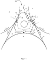
- Figure 1 shows an arrangement for a drying section of paper machine, board machine or the like according to one embodiment of the present invention.
- FIG. 1 shows an arrangement according to one embodiment of the present invention.
- the arrangement 100 comprises a first drying cylinder 2 and a second drying cylinder 3.
- the drying cylinders 2, 3 are arranged horizontally adjacent to each other, so that their longitudinal axes (not shown) are parallel with each other and arranged on a first level.
- a turning roll 4 is arranged in a space between the drying cylinders 2, 3 at a second level.
- a pocket space 5 is formed between the first drying cylinder 2, the second drying cylinder 3 and the turning roll 4, and a runnability component 1 is arranged into this pocket space 5.
- the runnability component 1 has an elongated box-like body 10.
- the body 10 of the runnability component 1 has an entry side surface 11, an exit side surface 12, a lower surface 13 and an upper surface 14.
- the entry side surface 11 comprises at least one sealing element 15, arranged towards the first drying cylinder for limiting the air flow to and from the pocket space 5.
- Another sealing element 15' is arranged in connection with the lower surface 13 of the body 10 of the runnability component 1.
- the sealing element 15' is intended to prevent the air flow from the exit side of the pocket space 5 to the entry side of the pocket space 5.
- the entry side surface 11 of the runnability component 1 may comprise further sealing elements, such as sealing nozzles 16, intended to eject air from the pocket space 5 and to prevent the entry of air into the pocket space 5.
- the turning directions of the drying cylinders 3, 4 are indicated with arrows A, B.
- the lower surface 13 of the runnability component 1 extends between the entry side surface 11 and exit side surface 12, and ends at the first junction 20.
- the upper surface 14 extends between the entry side surface 11 and the exit side surface 12, and is connected to the exit side surface 12 at a second junction 21.
- the exit side surface 12 of the runnability component 1 comprises a major surface portion 12' and a protruding deviation shape 17 with a main surface 17'.
- the deviation shape 17 is arranged closer to the first junction 20 than to the second junction 21, which means that the major surface portion 12' is located after the deviation shape 17 on the exit side, seen in the direction of movement of the wire 6.
- the length of the major surface portion 12' is indicated in Figure 1 with arrow II. The length may be, for example 100 - 350 mm.
- the main surface 17' of the deviation shape 17 and the major surface portion 12' may be connected by a first intermediate surface 18.
- the deviation shape 17 is directly connected with the first junction 20 by a second intermediate surface 19.
- the main surface 17' of the deviation shape 17 is arranged towards the second drying cylinder 3, at relatively close distance from the surface of the second drying cylinder 3.
- a fibre web, such as paper web, supported by a wire 6 is arranged to run from the turning roll 4 to the second drying cylinder 3 through the narrow passage.
- the movement direction of the web/wire is indicated with arrows C.
- the distance between the second drying cylinder 3 and the main surface 17' of the deviation shape 17, i.e. the width of the narrow passage, is indicated in Figure 1 with arrows III - III. Typically the distance is at most 40 mm, preferably at most 30 mm.
- the main surface 17' of the deviation shape 17 has a planar surface portion, which extends a length D, as indicated in Figure 1 .
- the length D of the planar portion may be 100 - 200 mm, preferably 120 - 150 mm, seen in direction of the exit side surface 12 from the first junction 20 to the second junction 21.
- the planar surface portion of the main surface 17' may be arranged in parallel plane with the main surface portion 12' of the exit side surface 12 or the main portion 17' of the deviation shape 17 and the main surface portion 12' of the exit side surface 12 may be arranged in an angle in relation to each other. Two possibilities of the latter embodiment are shown in Figure 1 with dashed lines.
- the narrow passage formed between the planar surface portion 17' and the wire 6 may widen or become narrower in direction of the movement of the wire.
- the tangent points of drying cylinders 2, 3 are indicated with dashed lines T. At the tangent point the wire separates from or meets the surface of drying cylinder 2, 3.
- the runnability component 1 is arranged so into the pocket space 5 that the planar surface portion of the protruding deviation shape 17 is located below the tangent point on the surface of the second drying cylinder 3.
- the conventional gap plates are schematically indicated in Figure 1 with dotted lines. Also the air duct inside the runnability component 1 is schematically indicated.
Landscapes
- Drying Of Solid Materials (AREA)
- Paper (AREA)
Abstract
Description
- The present invention relates to a runnability component and an arrangement for a drying section of a paper machine, board machine or the like according to the preambles of the enclosed independent claims.
- A drying section of a paper or board machine comprises heated drying cylinders, turning rolls and runnability components. The drying cylinders are typically arranged parallelly with each other on a first level and the turning rolls are arranged parallelly with each other on a second level. Pocket spaces are formed between each two adjacent drying cylinders and the turning roll situated between the drying cylinders. Runnability components are arranged into these pocket spaces. Runnability components are usually blow boxes or suction boxes, or they may provide both blowing and suction action for web stabilization. Usually the runnability components are elongated box-like components, comprising hollow interior spaces or channels for necessary transfer of air.
- Runnability components are used in the pocket spaces for creating and maintaining an underpressure, which helps to keep the web to be dried in contact with a wire and improves the overall runnability of the drying section. Runnability components may comprise one or more blowing means, suction means, sealing member(s) and/or other constructional features which aid in removing air away from the pocket space or obstruct the entry of air into the pocket space. Irrespective of existing runnability components, there is a need to find simple and effective ways to create and/or maintain an improved underpressure in a pocket space. Mechanically uncomplicated solutions, which are easy to construct and service, are preferable.
- An object of this invention is to minimise or even totally eliminate the disadvantages existing in the prior art.
- An object is to provide a runnability component and arrangement which creates and/or maintains a high underpressure in a pocket space of the drying section.
- A further object of the invention is to provide a runnability component which is uncomplicated to manufacture.
- These objects are attained with the invention having the characteristics presented below in the characterising parts of the independent claims.
- The embodiments mentioned in this text relate to all aspects of the invention, even if this is not always separately mentioned. The different embodiments can be freely combined with each other, if not explicitly stated otherwise.
- A typical runnability component according to the present invention for a drying section of a paper machine, board machine or the like has an elongated box-like body with
- an entry side surface comprising at least one sealing element,
- an exit side surface, arranged to a distance from the entry side surface in a horizontal direction,
- a lower surface, which extends from the entry side surface to the exit side surface, and which ends at a first junction, and
- an upper surface, which extends from the entry side surface to the exit side surface and which is connected to the exit side surface at a second junction,
- A typical arrangement according to the present invention for a drying section of paper machine, board machine or the like, comprises
- a first drying cylinder and a second drying cylinder, arranged adjacent to each other at a first level,
- a turning roll arranged in a space between the first drying cylinder and the second drying cylinder at a second level,
wherein the turning roll and the first and second drying cylinders define a pocket space formed between the first and second drying cylinders and the turning roll, - a runnability component according to the present invention arranged in the pocket space, wherein the exit side of the runnability component comprising a protruding deviation shape with a main surface is arranged to face the second drying cylinder, wherein the distance between the second drying cylinder and the main surface of the protruding deviation shape is at most 40 mm, preferably at most 30 mm.
- Now it has been surprisingly found that by arranging a protruding deviation shape on the lower part of the exit side surface of a runnability component it is possible to make the removal of air from the pocket space more efficient. The protruding deviation shape is simple to construct, provides unexpectedly effective function and it is adaptable in many different drying sections, even in existing paper and board machines. When the runnability component according to the invention is installed into a pocket space, the main surface of the protruding deviation shape is arranged close to the second drying cylinder. Thus a narrow passage between the main surface of the protruding deviation shape and the second drying cylinder is created. During the drying operation of the paper or board web, the web and the supporting wire move through the narrow passage, where the distance between the second drying cylinder and the main surface of the protruding deviation shape is at most 40 mm, preferably at most 30 mm. The air is free to flow past the protruding deviation shape, and the air removal from the pocket space is intensified and accelerated as the boundary layer of air associated with the moving wire facilitates the air movement in the narrow passage and away from the pocket space. Improved removal of air may make it possible to reduce the suction through the turning roll and may provide savings in overall energy consumption of the runnability component.
- In the present context, a high underpressure means a low absolute pressure and a low underpressure means a high absolute pressure. An underpressure means a pressure, which is lower than the normal atmospheric pressure ca. 1 bar, i.e. 100 kPa.
- According to the present invention the protruding deviation shape is arranged the closer to the first junction where the lower surface of the runnability component ends and from where the lower part is connected to the exit side surface, i.e. at the lower part of the exit side surface. The protruding deviation shape preferably forms an integral structural part of the exit side surface, i.e. the protruding deviation shape cannot be separated from the exit side surface. Preferably the protruding deviation shape is arranged immovable, and it is free of springs or other corresponding elasticity providing means.
- According to one embodiment, the exit side of the runnability component is preferably free of other protruding shapes or flow limiting means, e.g. doctor blades, air knives, blow nozzles, except the protruding deviation shape.
- The protruding deviation shape may be formed by mechanically processing the material of the exit side surface into a desired protruding shape, e.g. by folding or bending. It has been observed that the forming of the protruding deviation shape from the material of the exit side surface may increase and improve the structural rigidity of the runnability component and thus decrease the risks related to bending of the runnability component during the drying operation. Furthermore, the protruding deviation shape may increase the internal volume of the runnability component, giving more space for the flow channels and/or other internal components of the runnability component.
- The protruding deviation shape may have any suitable form, and the shape can be freely chosen, for example based on available processing technology and/or desired functional effects. The protruding deviation shape has at least a main surface which is arranged towards the second drying cylinder in the pocket space. The protruding deviation shape or its main surface may be curved, it may comprise at least one planar surface portion, it may be smoothly formed and/or it may be formed in a staggered or stepwise manner.
- Preferably the main surface of the protruding deviation shape comprises at least one a planar surface portion. It has been observed that when the protruding deviation shape has a planar surface portion, it is easy to create the narrow passage, which is formed between the protruding deviation shape and the second drying cylinder, with an appropriate length and form. According to one embodiment of the invention the planar surface portion of the protruding deviation shape may extend 100 - 200 mm, preferably 120 - 150 mm, seen in the direction from the first junction to the second junction. It has been observed that this length for the planar surface portion provides efficient air removal from the pocket space.
- Typically the exit side surface of the runnability component comprises a major surface portion between the second junction and the protruding deviation shape. The major surface portion is usually smooth and essentially planar and it extends from the second junction to a first inflection point, where the protruding deviation shape stars to protrude from the major surface portion. The distance between the second junction and the first inflection point, i.e. the length of the major surface portion, seen along the exit side surface from the inflection point to the second junction, may be 100 - 350 mm, preferably 200 - 300 mm. Between the second junction and the inflection point, seen in this direction, the distance between the entry side surface and the exit side surface usually increases, indicating that the planar major surface portion is usually slanted.
- In some embodiments, the planar major surface portion of the exit side continues in uniplanar fashion on both sides of the protruding deviation shape. This means that a first part of the major surface portion is located between the second junction and the first inflection (as described above) point and a second part of the major surface portion is located between the first junction and a second inflection point. The first part of the major surface portion is longer than the second part of the major surface portion. The second part of the major surface portion may be directly connected to the first junction or by an intermediate surface.
- According to one preferable embodiment, the protruding deviation shape is so close to the first junction that the major surface portion does not continue between the second inflection point and the first junction, but the protruding deviation shape and the first junction are connected with each other either directly or by a second intermediate surface. The second intermediate surface is preferably planar and an obtuse angle is formed between the main surface and the second intermediate surface.
- The protruding deviation shape may protrude at most 30 - 70 mm, preferably 45 - 55 mm, from a surface plane defined by the major surface portion of the exit side surface. This means that the difference between the surface plane defined by the major surface portion and a parallel deviation plane, arranged through the furthest point of the surface of the protruding deviation shape, is in the range of 30 - 70 mm, preferably 45 - 55 mm.
- When the main surface of the protruding deviation shape comprises at least one a planar surface portion, the planar surface portion and the major surface portion of the exit side surface are arranged essentially in different planes. The major surface portion and the planar surface portion may be arranged in parallel planes or in an angle in relation to each other. According to one preferable embodiment the planar surface portion of the protruding deviation shape and the major surface portion of the exit side surface are arranged in parallel planes.
- When arranged in the pocket space, the distance between the drying wire and the planar surface portion of the protruding deviation shape may preferably be constant. The runnability component may be arranged so that the protruding deviation shape is preferably completely located below the tangent point where the wire meets the surface of the second drying cylinder.
- According to another preferable embodiment, the distance between the surface plane defined by the major surface portion and the planar surface portion varies, when seen along the exit side surface in direction from the first junction to the second junction. In other words, the major surface portion and the planar surface portion may be arranged in an angle in relation to each other. The angle between the surface plane defined by the major surface portion and the plane of the planar surface portion may be, for example, in a range of 145 - 175 °.
- When the major surface portion and the planar surface portion are arranged in an angle in relation to each other, the distance between the planar surface portion and the wire varies along the length of the planar surface portion towards the inflection point. The distance may decrease, whereby the passage between the protruding deviation shape and the wire widens in direction of the movement of the wire, or the distance may increase whereby the passage between the protruding deviation shape and the wire narrows in direction of the movement of the wire. Preferably the distance decreases, i.e. the passage widens in direction of the movement of the wire.
- The the main surface of the protruding deviation shape may be directly connected to the major surface portion at the inflection point or the planar surface portion of the main surface and the major surface portion may be connected by a first intermediate surface, preferably planar intermediate surface.
- In context of the present invention, the runnability component may be a blow box and/or a suction box. In either case the runnability component has an elongated box-like body, which can be formed of any suitable metal, such as aluminium or steel. The runnability component has an entry side surface, an exit side surface, an upper surface and a lower surface. The lower surface and the upper surface are arranged to join or connect the entry side surface and the exit side surface at the first and second junction. The lower surface of the runnability component is the surface of the runnability component, which in the pocket space is located nearest to the turning roll, and which is arranged substantially towards the turning roll. According to one embodiment, at least one mechanical sealing element, such as labyrinth seal, may be arranged to the lower surface of the runnability component in order to restrict and/or prevent the flow of air form the exit side to the entry side or vice versa. The point where the lower surface ends on the exit side is denoted as first junction. Typically the first junction constitutes an angle, where the plane direction of the surface of the runnability component changes.
- In the arrangement according to the present invention the entry side surface of the runnability component is arranged to face the first drying cylinder. The entry side surface of the runnability component comprises at least one sealing element, which is arranged to eject air from the pocket space and/or prevent the entry of air to the pocket space. The sealing element on the entry side surface may be a blow element, a suction element, a mechanical sealing element or any combination of one or more of these elements. For example, the entry side surface of the runnability component may comprise a blow element and one or more mechanical sealing elements, such as sealing strips and/or labyrinth sealings.
- The exit side surface of the runnability component is arranged to face the second drying cylinder. The exit side surface is preferably continuous, i.e. it is free of suction elements, blowing elements and/or sealing elements.
- The runnability component according to the present invention is arranged in a pocket space, which is defined by a first drying cylinder and a second drying cylinder and a turning roll between them. The first and second drying cylinders are parallel, i.e. their longitudinal axes are parallel with each other, and they are arranged at a distance from each other. The adjacent drying cylinders are arranged horizontally on a first level and the turning roll is arranged between the two adjacent drying cylinders so that the longitudinal axis of the turning roll is substantially parallel with the longitudinal axes of the first and second drying cylinders, but located on a second level in the vertical direction. Turning roll is thus arranged on a higher or lower level than the first and second drying cylinders, typically on a lower level. Furthermore, the turning roll is placed between the drying cylinders so that its surface does not touch the surfaces of the drying cylinders, i.e. is free from contact with the drying cylinder surfaces. In a typical paper machine or board machine the box-like runnability component, the drying cylinders and the turning rolls are elongated in the cross-direction of the machine, and they extend substantially over the entire width of the web run. Therefore the pocket space defined by them is also elongated in the cross-direction of the paper machine. The distance between the first end and the second end of the elongated box-like body of the runnability component may be 5 - 15 m, preferably 8 - 12 m. The ends of the pocket space are typically sealed, for example by means of end plates according to prior art, such as gap plates. The vertical end plates are arranged in machine direction, on both ends of the pocket space.
- The arrangement according to the invention may preferably comprise a drying wire, running from the first drying cylinder to the second drying cylinder via an outer surface of the turning roll. The drying wire supports the web to be dried and forms the web run together with the web. The passage formed between the drying wire and the main surface of the protruding deviation shape may preferably have a length in a range of 100 - 200 mm, preferably 120 - 150 mm, seen in the direction of the movement of the drying wire. According to one embodiment of the invention the distance between the drying wire and the main surface of the protruding deviation shape is in a range of 10 - 40 mm, preferably 20 - 30 mm.
- A closing nip is formed between the drying wire and the second drying cylinder at a location where the drying wire runs to the second drying cylinder. The runnability component may preferably arranged in the pocket space in such a manner that the protruding deviation shape is located before the closing nip.
- The runnability component and the arrangement of the present invention are especially suitable for a drying section of a paper machine or a board machine. The runnability component is especially suitable for paper machines or board machines where the speed of the wire is >1000 m/min, preferably >1200 m/min, more preferably >1500 m/min.
- A non-limiting example of the present invention is presented in more detail in the following schematical drawings, where
Figure 1 shows an arrangement for a drying section of paper machine, board machine or the like according to one embodiment of the present invention. -
Figure 1 shows an arrangement according to one embodiment of the present invention. The arrangement 100 comprises afirst drying cylinder 2 and asecond drying cylinder 3. The dryingcylinders roll 4 is arranged in a space between the dryingcylinders pocket space 5 is formed between thefirst drying cylinder 2, thesecond drying cylinder 3 and the turningroll 4, and arunnability component 1 is arranged into thispocket space 5. - The
runnability component 1 has an elongated box-like body 10. Thebody 10 of therunnability component 1 has anentry side surface 11, anexit side surface 12, alower surface 13 and anupper surface 14. Theentry side surface 11 comprises at least one sealingelement 15, arranged towards the first drying cylinder for limiting the air flow to and from thepocket space 5. Another sealing element 15' is arranged in connection with thelower surface 13 of thebody 10 of therunnability component 1. The sealing element 15' is intended to prevent the air flow from the exit side of thepocket space 5 to the entry side of thepocket space 5. Theentry side surface 11 of therunnability component 1 may comprise further sealing elements, such as sealingnozzles 16, intended to eject air from thepocket space 5 and to prevent the entry of air into thepocket space 5. The turning directions of the dryingcylinders - The
lower surface 13 of therunnability component 1 extends between theentry side surface 11 andexit side surface 12, and ends at thefirst junction 20.. Similarly, theupper surface 14 extends between theentry side surface 11 and theexit side surface 12, and is connected to theexit side surface 12 at asecond junction 21. - The
exit side surface 12 of therunnability component 1 comprises a major surface portion 12' and aprotruding deviation shape 17 with a main surface 17'. On theexit side surface 12 thedeviation shape 17 is arranged closer to thefirst junction 20 than to thesecond junction 21, which means that the major surface portion 12' is located after thedeviation shape 17 on the exit side, seen in the direction of movement of the wire 6. The length of the major surface portion 12' is indicated inFigure 1 with arrow II. The length may be, for example 100 - 350 mm. The main surface 17' of thedeviation shape 17 and the major surface portion 12' may be connected by a firstintermediate surface 18. Thedeviation shape 17 is directly connected with thefirst junction 20 by a secondintermediate surface 19. - The main surface 17' of the
deviation shape 17 is arranged towards thesecond drying cylinder 3, at relatively close distance from the surface of thesecond drying cylinder 3. Thus a narrow passage between the main surface 17' of thedeviation shape 17 and thesecond drying cylinder 3 is formed. A fibre web, such as paper web, supported by a wire 6 is arranged to run from the turningroll 4 to thesecond drying cylinder 3 through the narrow passage. The movement direction of the web/wire is indicated with arrows C. The distance between thesecond drying cylinder 3 and the main surface 17' of thedeviation shape 17, i.e. the width of the narrow passage, is indicated inFigure 1 with arrows III - III. Typically the distance is at most 40 mm, preferably at most 30 mm. - In the embodiment present in
Figure 1 the main surface 17' of thedeviation shape 17 has a planar surface portion, which extends a length D, as indicated inFigure 1 . Typically the length D of the planar portion may be 100 - 200 mm, preferably 120 - 150 mm, seen in direction of the exit side surface 12 from thefirst junction 20 to thesecond junction 21. It is also seen fromFigure 1 that the planar surface portion of the main surface 17' may be arranged in parallel plane with the main surface portion 12' of theexit side surface 12 or the main portion 17' of thedeviation shape 17 and the main surface portion 12' of theexit side surface 12 may be arranged in an angle in relation to each other. Two possibilities of the latter embodiment are shown inFigure 1 with dashed lines. When the major surface portion 12' and the planar surface portion 17' are arranged in an angle in relation to each other, the narrow passage formed between the planar surface portion 17' and the wire 6 may widen or become narrower in direction of the movement of the wire. - The tangent points of drying
cylinders cylinder runnability component 1 is arranged so into thepocket space 5 that the planar surface portion of theprotruding deviation shape 17 is located below the tangent point on the surface of thesecond drying cylinder 3. - The conventional gap plates are schematically indicated in
Figure 1 with dotted lines. Also the air duct inside therunnability component 1 is schematically indicated. - Even if the invention was described with reference to what at present seems to be the most practical and preferred embodiments, it is appreciated that the invention shall not be limited to the embodiments described above, but the invention is intended to cover also different modifications and equivalent technical solutions within the scope of the enclosed claims.
Claims (15)
- A runnability component for a drying section of paper machine, board machine or the like, the runnability component having an elongated box-like body with- an entry side surface comprising at least one sealing element,- an exit side surface, arranged to a distance from the entry side surface in a horizontal direction,- a lower surface, which extends from the entry side surface to the exit side surface, and which ends at a first junction, and- an upper surface, which extends from the entry side surface to the exit side surface, and which is connected to the exit side surface at a second junction,characterised in that
the exit side surface comprises a protruding deviation shape with a main surface, which protruding deviation shape is arranged closer to the first junction than to the second junction. - Runnability component according to claim 1, characterised in that the exit side surface has a major surface portion and the protruding deviation shape protrudes at most 30 - 70 mm, preferably 45 - 55 mm, from a surface plane defined by the major surface portion.
- Runnability component according to claim 1 or 2, characterised in that the main surface of the protruding deviation shape comprises at least one planar surface portion.
- Runnability component according to claim 3, characterised in that the planar surface portion of the protruding deviation shape extends 100 - 200 mm, preferably 120 - 150 mm, seen in direction from the first junction to the second junction.
- Runnability component according to claim 3 or 5, characterised in that the major surface portion and the planar surface portion are arranged in parallel planes.
- Runnability component according to claim 3 or 4, characterised in that the major surface portion and the planar surface portion are arranged in an angle in relation to each other.
- Runnability component according to claim 6, characterised in that the angle between a surface plane defined by the major surface portion and a plane defined by the planar surface portion is in a range of 145 - 175 °.
- Runnability component according to any of claims 3 - 7, characterised in that the main surface of the protruding deviation shape is directly connected to the major surface portion at an inflection point or the planar surface portion of the main surface and the major surface portion are connected by a first intermediate surface.
- Runnability component according to any of claims 2 - 8, characterised in that the length of the major surface portion is 100 - 350 mm, preferably 200 - 300 mm, from the inflection point to the second junction.
- An arrangement for a drying section of paper machine, board machine or the like, comprising- a first drying cylinder and a second drying cylinder, arranged adjacent to each other at a first level,- a turning roll arranged in a space between the first drying cylinder and the second drying cylinder at a second level,
wherein the turning roll and the first and second drying cylinders define a pocket space formed between the first and second drying cylinders and the turning roll,- a runnability component according to any of claims 1 - 9 arranged in the pocket space, wherein the exit side of the runnability component comprising a protruding deviation shape with a main surface is arranged to face the second drying cylinder,characterised in that
the distance between the second drying cylinder and the main surface of the protruding deviation shape is at most 40 mm, preferably at most 30 mm. - Arrangement according to claim 10, characterised in that the arrangement comprises a drying wire, running from the first drying cylinder to the second drying cylinder via the turning roll, wherein a passage having a length in a range of 100 - 200 mm, preferably 120 - 150 mm, is formed between the drying wire and the main surface of the protruding deviation shape, seen in the direction of the movement of the drying wire.
- Arrangement according to claim 11, characterised in that the distance between the drying wire and the main surface of the protruding deviation shape in the passage is in a range of 10 - 40 mm, preferably 20 - 30 mm.
- Arrangement according to claim 11 or 12, characterised in that the distance between the drying wire and the main surface of the protruding deviation shape in the passage is constant.
- Arrangement according to claim 11 or 12, characterised in that the passage between the main surface of the protruding deviation shape and the second drying cylinder is arranged to widen in direction of the movement of the wire.
- Arrangement according to claim 11 - 14, characterised in that the protruding deviation shape is located below a tangent point where the drying wire meets the surface of the second drying cylinder.
Priority Applications (2)
| Application Number | Priority Date | Filing Date | Title |
|---|---|---|---|
| EP21178779.1A EP4101978A1 (en) | 2021-06-10 | 2021-06-10 | A runnability component and an arrangement for a drying section |
| CN202210655882.XA CN115467186B (en) | 2021-06-10 | 2022-06-10 | Runnability component and device for a dryer section |
Applications Claiming Priority (1)
| Application Number | Priority Date | Filing Date | Title |
|---|---|---|---|
| EP21178779.1A EP4101978A1 (en) | 2021-06-10 | 2021-06-10 | A runnability component and an arrangement for a drying section |
Publications (1)
| Publication Number | Publication Date |
|---|---|
| EP4101978A1 true EP4101978A1 (en) | 2022-12-14 |
Family
ID=76707944
Family Applications (1)
| Application Number | Title | Priority Date | Filing Date |
|---|---|---|---|
| EP21178779.1A Pending EP4101978A1 (en) | 2021-06-10 | 2021-06-10 | A runnability component and an arrangement for a drying section |
Country Status (1)
| Country | Link |
|---|---|
| EP (1) | EP4101978A1 (en) |
Citations (3)
| Publication number | Priority date | Publication date | Assignee | Title |
|---|---|---|---|---|
| WO1998048109A1 (en) * | 1997-04-23 | 1998-10-29 | Valmet Corporation | A blow box to be used in the drying section of a paper machine and a method for tightening a pocket provided with a blow box in the drying section of a paper machine |
| WO2006131589A2 (en) * | 2005-06-06 | 2006-12-14 | Metso Paper, Inc. | Arrangement and method for sealing of a pocket space between drying cylinders in a paper machine or similar, runnability component, and method for manufacturing a runnability component |
| WO2010084241A1 (en) * | 2009-01-20 | 2010-07-29 | Metso Paper, Inc. | Method and arrangement for facilitating web threading in a paper machine's drying section |
-
2021
- 2021-06-10 EP EP21178779.1A patent/EP4101978A1/en active Pending
Patent Citations (3)
| Publication number | Priority date | Publication date | Assignee | Title |
|---|---|---|---|---|
| WO1998048109A1 (en) * | 1997-04-23 | 1998-10-29 | Valmet Corporation | A blow box to be used in the drying section of a paper machine and a method for tightening a pocket provided with a blow box in the drying section of a paper machine |
| WO2006131589A2 (en) * | 2005-06-06 | 2006-12-14 | Metso Paper, Inc. | Arrangement and method for sealing of a pocket space between drying cylinders in a paper machine or similar, runnability component, and method for manufacturing a runnability component |
| WO2010084241A1 (en) * | 2009-01-20 | 2010-07-29 | Metso Paper, Inc. | Method and arrangement for facilitating web threading in a paper machine's drying section |
Also Published As
| Publication number | Publication date |
|---|---|
| CN115467186A (en) | 2022-12-13 |
Similar Documents
| Publication | Publication Date | Title |
|---|---|---|
| EP1543194B1 (en) | Forming of a paper or board web in a twin-wire former | |
| EP1979534B1 (en) | Method and drying group arrangement for a fibre-web machine, such as a paper or board machine | |
| FI73259C (en) | Method and apparatus in the cylinder dryer of a paper machine | |
| US8011115B2 (en) | Method and device in a dryer section of a fibre-web machine, such as a paper or board machine | |
| US10094067B2 (en) | Production line for producing fiber webs and a cooler | |
| EP4101978A1 (en) | A runnability component and an arrangement for a drying section | |
| CN103174050A (en) | Runnability component and method for drying a paper web | |
| US8123908B2 (en) | Runnability component and a method for controlling underpressure in a drying section of a paper machine or the like | |
| US6875309B2 (en) | Twin wire former | |
| US8117765B2 (en) | Apparatus and method of sealing of a pocket space between drying cylinders in a paper machine or a board machine | |
| US6662468B2 (en) | Dryer section of a paper or board machine | |
| US7435315B2 (en) | Arrangement for stabilizing a web | |
| US20110290442A1 (en) | Twin fabric forming section with multiple drainage shoes | |
| US20070245589A1 (en) | Runnability of Web in a Material Web Machine | |
| EP2841643B1 (en) | Forming section | |
| FI20245653A1 (en) | Drying group and a drying section for a fiber web production line | |
| CN114541166A (en) | Can form steady carton and paper machine in doublestage vacuum area | |
| FI122926B (en) | Arrangement and procedure for saving energy in dryer section of paper machine or equivalent | |
| EP2126204A1 (en) | A system in a web forming machine for guiding the web in connection with a grooved roll |
Legal Events
| Date | Code | Title | Description |
|---|---|---|---|
| PUAI | Public reference made under article 153(3) epc to a published international application that has entered the european phase |
Free format text: ORIGINAL CODE: 0009012 |
|
| STAA | Information on the status of an ep patent application or granted ep patent |
Free format text: STATUS: THE APPLICATION HAS BEEN PUBLISHED |
|
| AK | Designated contracting states |
Kind code of ref document: A1 Designated state(s): AL AT BE BG CH CY CZ DE DK EE ES FI FR GB GR HR HU IE IS IT LI LT LU LV MC MK MT NL NO PL PT RO RS SE SI SK SM TR |
|
| STAA | Information on the status of an ep patent application or granted ep patent |
Free format text: STATUS: REQUEST FOR EXAMINATION WAS MADE |
|
| 17P | Request for examination filed |
Effective date: 20230613 |
|
| RBV | Designated contracting states (corrected) |
Designated state(s): AL AT BE BG CH CY CZ DE DK EE ES FI FR GB GR HR HU IE IS IT LI LT LU LV MC MK MT NL NO PL PT RO RS SE SI SK SM TR |
|
| STAA | Information on the status of an ep patent application or granted ep patent |
Free format text: STATUS: EXAMINATION IS IN PROGRESS |
|
| 17Q | First examination report despatched |
Effective date: 20260305 |