EP4101922A1 - Cell culturing device, cell culturing method, and method for producing product - Google Patents
Cell culturing device, cell culturing method, and method for producing product Download PDFInfo
- Publication number
- EP4101922A1 EP4101922A1 EP21771343.7A EP21771343A EP4101922A1 EP 4101922 A1 EP4101922 A1 EP 4101922A1 EP 21771343 A EP21771343 A EP 21771343A EP 4101922 A1 EP4101922 A1 EP 4101922A1
- Authority
- EP
- European Patent Office
- Prior art keywords
- culture
- cells
- cell culture
- cell
- gap
- Prior art date
- Legal status (The legal status is an assumption and is not a legal conclusion. Google has not performed a legal analysis and makes no representation as to the accuracy of the status listed.)
- Pending
Links
Images




Classifications
-
- B—PERFORMING OPERATIONS; TRANSPORTING
- B01—PHYSICAL OR CHEMICAL PROCESSES OR APPARATUS IN GENERAL
- B01F—MIXING, e.g. DISSOLVING, EMULSIFYING OR DISPERSING
- B01F27/00—Mixers with rotary stirring devices in fixed receptacles; Kneaders
- B01F27/05—Stirrers
- B01F27/11—Stirrers characterised by the configuration of the stirrers
- B01F27/111—Centrifugal stirrers, i.e. stirrers with radial outlets; Stirrers of the turbine type, e.g. with means to guide the flow
- B01F27/1111—Centrifugal stirrers, i.e. stirrers with radial outlets; Stirrers of the turbine type, e.g. with means to guide the flow with a flat disc or with a disc-like element equipped with blades, e.g. Rushton turbine
-
- C—CHEMISTRY; METALLURGY
- C12—BIOCHEMISTRY; BEER; SPIRITS; WINE; VINEGAR; MICROBIOLOGY; ENZYMOLOGY; MUTATION OR GENETIC ENGINEERING
- C12M—APPARATUS FOR ENZYMOLOGY OR MICROBIOLOGY; APPARATUS FOR CULTURING MICROORGANISMS FOR PRODUCING BIOMASS, FOR GROWING CELLS OR FOR OBTAINING FERMENTATION OR METABOLIC PRODUCTS, i.e. BIOREACTORS OR FERMENTERS
- C12M3/00—Tissue, human, animal or plant cell, or virus culture apparatus
- C12M3/02—Tissue, human, animal or plant cell, or virus culture apparatus with means providing suspensions
-
- B—PERFORMING OPERATIONS; TRANSPORTING
- B01—PHYSICAL OR CHEMICAL PROCESSES OR APPARATUS IN GENERAL
- B01F—MIXING, e.g. DISSOLVING, EMULSIFYING OR DISPERSING
- B01F27/00—Mixers with rotary stirring devices in fixed receptacles; Kneaders
- B01F27/80—Mixers with rotary stirring devices in fixed receptacles; Kneaders with stirrers rotating about a substantially vertical axis
-
- B—PERFORMING OPERATIONS; TRANSPORTING
- B01—PHYSICAL OR CHEMICAL PROCESSES OR APPARATUS IN GENERAL
- B01F—MIXING, e.g. DISSOLVING, EMULSIFYING OR DISPERSING
- B01F27/00—Mixers with rotary stirring devices in fixed receptacles; Kneaders
- B01F27/80—Mixers with rotary stirring devices in fixed receptacles; Kneaders with stirrers rotating about a substantially vertical axis
- B01F27/808—Mixers with rotary stirring devices in fixed receptacles; Kneaders with stirrers rotating about a substantially vertical axis with stirrers driven from the bottom of the receptacle
-
- B—PERFORMING OPERATIONS; TRANSPORTING
- B01—PHYSICAL OR CHEMICAL PROCESSES OR APPARATUS IN GENERAL
- B01F—MIXING, e.g. DISSOLVING, EMULSIFYING OR DISPERSING
- B01F33/00—Other mixers; Mixing plants; Combinations of mixers
- B01F33/45—Magnetic mixers; Mixers with magnetically driven stirrers
- B01F33/453—Magnetic mixers; Mixers with magnetically driven stirrers using supported or suspended stirring elements
- B01F33/4534—Magnetic mixers; Mixers with magnetically driven stirrers using supported or suspended stirring elements using a rod for supporting the stirring element, e.g. stirrer sliding on a rod or mounted on a rod sliding in a tube
-
- C—CHEMISTRY; METALLURGY
- C07—ORGANIC CHEMISTRY
- C07K—PEPTIDES
- C07K16/00—Immunoglobulins [IG], e.g. monoclonal or polyclonal antibodies
-
- C—CHEMISTRY; METALLURGY
- C12—BIOCHEMISTRY; BEER; SPIRITS; WINE; VINEGAR; MICROBIOLOGY; ENZYMOLOGY; MUTATION OR GENETIC ENGINEERING
- C12M—APPARATUS FOR ENZYMOLOGY OR MICROBIOLOGY; APPARATUS FOR CULTURING MICROORGANISMS FOR PRODUCING BIOMASS, FOR GROWING CELLS OR FOR OBTAINING FERMENTATION OR METABOLIC PRODUCTS, i.e. BIOREACTORS OR FERMENTERS
- C12M23/00—Constructional details, e.g. recesses, hinges
- C12M23/02—Form or structure of the vessel
- C12M23/14—Bags
-
- C—CHEMISTRY; METALLURGY
- C12—BIOCHEMISTRY; BEER; SPIRITS; WINE; VINEGAR; MICROBIOLOGY; ENZYMOLOGY; MUTATION OR GENETIC ENGINEERING
- C12M—APPARATUS FOR ENZYMOLOGY OR MICROBIOLOGY; APPARATUS FOR CULTURING MICROORGANISMS FOR PRODUCING BIOMASS, FOR GROWING CELLS OR FOR OBTAINING FERMENTATION OR METABOLIC PRODUCTS, i.e. BIOREACTORS OR FERMENTERS
- C12M27/00—Means for mixing, agitating or circulating fluids in the vessel
- C12M27/02—Stirrer or mobile mixing elements
-
- C—CHEMISTRY; METALLURGY
- C12—BIOCHEMISTRY; BEER; SPIRITS; WINE; VINEGAR; MICROBIOLOGY; ENZYMOLOGY; MUTATION OR GENETIC ENGINEERING
- C12M—APPARATUS FOR ENZYMOLOGY OR MICROBIOLOGY; APPARATUS FOR CULTURING MICROORGANISMS FOR PRODUCING BIOMASS, FOR GROWING CELLS OR FOR OBTAINING FERMENTATION OR METABOLIC PRODUCTS, i.e. BIOREACTORS OR FERMENTERS
- C12M29/00—Means for introduction, extraction or recirculation of materials, e.g. pumps
- C12M29/04—Filters; Permeable or porous membranes or plates, e.g. dialysis
-
- C—CHEMISTRY; METALLURGY
- C12—BIOCHEMISTRY; BEER; SPIRITS; WINE; VINEGAR; MICROBIOLOGY; ENZYMOLOGY; MUTATION OR GENETIC ENGINEERING
- C12M—APPARATUS FOR ENZYMOLOGY OR MICROBIOLOGY; APPARATUS FOR CULTURING MICROORGANISMS FOR PRODUCING BIOMASS, FOR GROWING CELLS OR FOR OBTAINING FERMENTATION OR METABOLIC PRODUCTS, i.e. BIOREACTORS OR FERMENTERS
- C12M29/00—Means for introduction, extraction or recirculation of materials, e.g. pumps
- C12M29/18—External loop; Means for reintroduction of fermented biomass or liquid percolate
-
- C—CHEMISTRY; METALLURGY
- C12—BIOCHEMISTRY; BEER; SPIRITS; WINE; VINEGAR; MICROBIOLOGY; ENZYMOLOGY; MUTATION OR GENETIC ENGINEERING
- C12N—MICROORGANISMS OR ENZYMES; COMPOSITIONS THEREOF; PROPAGATING, PRESERVING, OR MAINTAINING MICROORGANISMS; MUTATION OR GENETIC ENGINEERING; CULTURE MEDIA
- C12N5/00—Undifferentiated human, animal or plant cells, e.g. cell lines; Tissues; Cultivation or maintenance thereof; Culture media therefor
- C12N5/0062—General methods for three-dimensional culture
-
- C—CHEMISTRY; METALLURGY
- C12—BIOCHEMISTRY; BEER; SPIRITS; WINE; VINEGAR; MICROBIOLOGY; ENZYMOLOGY; MUTATION OR GENETIC ENGINEERING
- C12N—MICROORGANISMS OR ENZYMES; COMPOSITIONS THEREOF; PROPAGATING, PRESERVING, OR MAINTAINING MICROORGANISMS; MUTATION OR GENETIC ENGINEERING; CULTURE MEDIA
- C12N5/00—Undifferentiated human, animal or plant cells, e.g. cell lines; Tissues; Cultivation or maintenance thereof; Culture media therefor
- C12N5/06—Animal cells or tissues; Human cells or tissues
-
- C—CHEMISTRY; METALLURGY
- C12—BIOCHEMISTRY; BEER; SPIRITS; WINE; VINEGAR; MICROBIOLOGY; ENZYMOLOGY; MUTATION OR GENETIC ENGINEERING
- C12P—FERMENTATION OR ENZYME-USING PROCESSES TO SYNTHESISE A DESIRED CHEMICAL COMPOUND OR COMPOSITION OR TO SEPARATE OPTICAL ISOMERS FROM A RACEMIC MIXTURE
- C12P21/00—Preparation of peptides or proteins
- C12P21/02—Preparation of peptides or proteins having a known sequence of two or more amino acids, e.g. glutathione
Definitions
- the disclosed technology relates to a cell culture device, a cell culture method, and a production method of a product.
- JP2015-147206A discloses a stirrer comprising an impeller attached to a rotating shaft, and a housing assembly.
- the housing assembly comprises an upper seal assembly and a lower seal assembly.
- the upper seal assembly and the lower seal assembly each have a central channel for receiving the rotating shaft, and include a seal having a cyclic opening portion.
- a stirring culture in which the cells are cultured while stirring the cell suspension is generally applied.
- Stirring of the cell suspension promotes the supply of oxygen and nutrients to the cells.
- a stirring device having a rotating stirring blade is used for stirring the cell suspension.
- the cells may be damaged by the shear generated by the stirring, which may cause problems such as a decrease in the cell proliferation rate and a decrease in the viability.
- the disclosed technology has been made in view of the above-mentioned points, and an object thereof is to inhibit damage to cells caused by stirring a cell suspension.
- a cell culture device includes: a culture vessel that accommodates a cell suspension containing cells and a culture medium; and a stirring device that is provided at a bottom part of the culture vessel to stir the cell suspension accommodated in the culture vessel.
- the stirring device has a shaft part; a rotating part that has a hole part into which the shaft part is inserted, and is provided to have a gap of 100 ⁇ m or more between an interior wall demarcating the hole part and the shaft part so that the rotation part is rotatable with the shaft part as a rotation axis; and a closing part that closes an end part of the gap in an axial direction of the rotation axis.
- a dimension of the gap is preferably 400 ⁇ m or less.
- the closing part may be provided at one end part of the gap in the axial direction of the rotation axis, or may be provided at both end parts of the gap in the axial direction of the rotation axis.
- the rotating part may be rotated by a magnetic force.
- the closing part may be configured to have a packing made of polymer.
- the culture vessel may have the form of a bag.
- a cell culture method is a cell culture method which uses the above-mentioned cell culture device, the method including culturing cells while stirring a cell suspension accommodated in a culture vessel by rotation of a rotating part.
- the cells are preferably cultured at a shear rate ⁇ [sec -1 ] defined by Equation (I) in a range of 200 sec -1 or more and 3200 sec -1 or less, in a case where a dimension of a gap is t [ ⁇ m], and a rotation rate of the rotating part is s [m/sec].
- ⁇ s / t ⁇ 10 ⁇ 6
- the culture scheme may be a perfusion culture scheme, or may be a fed-batch scheme.
- the cells to be cultured may be Chinese Hamster Ovary (CHO) cells.
- a production method of a product according to the disclosed technology is a production method of a product which is for producing a product produced from cells cultured by the above-mentioned cell culture method, the method including a step of collecting a culture medium containing the product from a culture vessel.
- the product may be an antibody.
- the damage to cells caused by stirring a cell suspension can be inhibited.
- Fig. 1 is a view showing an example of the configuration of a cell culture device 100 according to the embodiment of the disclosed technology.
- the cell culture device 100 includes a culture vessel 10 accommodating a cell suspension 12 containing cells and a culture medium; a filter unit 20 having a filter membrane 24 that applies a membrane separation treatment to the cell suspension extracted from the culture vessel 10; a flow channel 51 through which the cell suspension moving between the filter unit 20 and the culture vessel 10 passes; a flow channel 53 through which components that have permeated through the filter membrane 24 passes; and a collecting tank 40 connected to the flow channel 53.
- the cell culture device 100 can be suitably used for cell culture by a perfusion culture scheme in which a fresh culture medium is continuously supplied to the culture vessel 10 while a culture medium containing a product such as an antibody is continuously extracted from the culture vessel 10.
- the form of the culture vessel 10 is not particularly limited, but a bag type having the capacity of, for example, 10 L or more, which is used for mass culture of cells, can be preferably used.
- a stirring device 30 is provided at the bottom part of the culture vessel 10. The detailed configuration of the stirring device 30 will be described later.
- One end of the flow channel 51 is inserted into the cell suspension 12, and the other end is connected to a flow port 20a of the filter unit 20.
- the filter unit 20 includes a vessel 21; and a filter membrane 24 that partitions the space inside the vessel 21 into a supply side 22 and a permeation side 23 and applies a membrane separation treatment to the cell suspension 12 extracted from the culture vessel 10. Furthermore, on the supply side 22, the filter unit 20 has flow ports 20a and 20b through which the cell suspension 12 flows. The cell suspension 12 extracted from the culture vessel 10 flows into the inside of the vessel 21 from the flow port 20a and passes through the filter membrane 24 until reaching the flow port 20b.
- the filter unit 20 performs a membrane separation treatment by a tangential flow method of pouring a liquid as an object of the membrane separation treatment so as to cause the liquid to flow along the membrane surface of a filter membrane 24 (in a direction parallel to the membrane surface) and sending small-sized components toward the permeation side 23.
- the flow channel 52 is connected to the flow port 20b, and the other end of the flow channel 52 is connected to a pump PU1.
- the pump PU1 is a diaphragm pump, for example, and by operating the pump PU1, the cell suspension 12 extracted from the culture vessel 10 forms a reciprocating flow along the membrane surface of the filter membrane 24.
- the flow channel can be configured such that the cell suspension 12 extracted from the culture vessel 10 forms a flow that circulates in one direction along the membrane surface of the filter membrane 24.
- the cells contained in the cell suspension 12 do not permeate through the filter membrane 24, but are returned to the culture vessel 10 via the flow channel 51.
- the product such as antibodies contained in the cell suspension 12 permeates through the filter membrane 24, and is discharged to the outside of the vessel 21 through a discharge port 20c provided on the permeation side 23.
- the flow channel 53 provided with a pump PU2 is connected, and a permeation liquid containing the product such as antibodies which has permeated through the permeation side 23 is collected in the collecting tank 40 via the flow channel 53.
- a hollow fiber membrane can be used as the filter membrane 24.
- a risk of cells permeating into the permeation side can be reduced, as compared to the case of using a mesh filter.
- a risk of the occurrence of clogging caused by cells infiltrating into the filter membrane 24 can be reduced. Thereby, loss of cells can be reduced.
- the product such as antibodies contained in the permeation liquid that has permeated through the filter membrane 24 and collected in the collecting tank 40 is sent, via a flow channel 56, to a purification treatment unit (not shown in the drawing) in which purification of antibodies is performed.
- the cell culture device 100 has a flow channel 54 for supplying a fresh culture medium to the culture vessel 10; and a pump PU3 provided in the middle of the flow channel 54.
- a cell bleeding treatment of taking out a portion of cells inside the culture vessel 10 at an appropriate timing during the culture period is carried out.
- the cells in the culture vessel 10 are discharged to the outside of the culture vessel 10 via a flow channel 55.
- the cell culture device 100 shown in Fig. 1 performs a separation treatment by means of the membrane separation treatment using the filter unit 20; however, it is also possible to replace the filter unit 20 with a treatment unit of performing a separation treatment according to a sonic agglomeration method.
- Fig. 2A is a plan view showing an example of the configuration of the stirring device 30.
- Fig. 2B is a cross-sectional view taken along the line 2B-2B in Fig. 2A .
- the stirring device 30 has a pedestal part 31, a shaft part 32, and a rotating part 33.
- the pedestal part 31 is a plate-shaped member, and is fixed to the bottom surface of the culture vessel 10.
- the shaft part 32 is a cylindrical member extending in the direction perpendicular to the surface of the pedestal part 31.
- the shaft part 32 may be configured integrally with the pedestal part 31, or may be configured as a separate body from the pedestal part 31.
- the rotating part 33 has a main body 34 and a leaf blade part 35.
- the main body 34 has a cylindrical shape having the height as high as the length of the shaft part 32 in the axial direction.
- the main body 34 has a hole part 36 penetrating the main body 34 in the center thereof.
- the shaft part 32 is inserted into the hole part 36.
- the main body 34 can rotate with the shaft part 32 as a rotation axis.
- a gap (clearance) 37 is secured between the inner wall on the hole part side of the main body (the inner wall demarcating the hole part 36) and the shaft part 32. That is, the rotating part 33 is not in contact with the shaft part 32.
- the main body 34 is provided with three leaf blade parts 35.
- the leaf blade part 35 has a portion protruding from the outer edge of the main body 34, and functions as a stirring blade for stirring the cell suspension 12 by rotating with the main body 34. Stirring of the cell suspension 12 promotes the supply of oxygen and nutrients to the cells.
- the shape of the leaf blade part 35 is not particularly limited, and may be any shape that promotes stirring.
- the leaf blade part 35 may be configured integrally with the main body 34, or may be configured as a separate body from the main body 34. Furthermore, the number of the leaf blade parts 35 may be two or less, or may be four or more.
- the stirring device 30 has a closing part 38 that closes the upper end part of the gap 37 in the axial direction of the rotation axis.
- the closing part 38 has the form of a ring shape corresponding to the shape seen from the upper side of the gap 37 in the axial direction.
- the surface of the closing part 38 in contact with the shaft part 32 may be adhered to the shaft part 32.
- the surface of the closing part 38 in contact with the inner wall on the hole part side of the main body 34 is slidable with respect to the inner wall on the hole part side of the main body 34.
- the surface of the closing part 38 in contact with the inner wall on the hole part side of the main body 34 may be adhered to the inner wall on the hole part side of the main body 34.
- the surface of the closing part 38 in contact with the shaft part 32 is slidable with respect to the shaft part 32.
- a packing made of polymer can be suitably used as the closing part 38.
- the stirring device 30 is in a state of being immersed in the cell suspension 12.
- the closing part 38 closes the end part of the gap 37, the inflow of the cell suspension 12 into the gap 37 can be inhibited.
- the closing part 38 serves as resistance to the rotation of the rotating part 33, but the contact pressure of the sliding surface is adjusted to such an extent that the rotation of the rotating part 33 is not hindered.
- the rotating part 33 is rotated by a magnetic force.
- the stirring device 30 has a driving unit 39 installed near the rotating part 33.
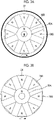
- Fig. 3A is a view showing an example of the internal configuration of the driving unit 39.
- the driving unit 39 has a circular surface facing the bottom surface of the rotating part 33, and a center point P of this circle is aligned with the position (that is, the rotation axis of the rotating part 33) corresponding to the shaft part 32.
- the driving unit 39 has a ring-shaped magnet 60A having a center point at the center point P, and a plurality of magnets 60B disposed radially around the center point P.
- the plurality of magnets 60B are disposed such that the polarities on the side facing the rotating part 33 are alternately reversed.
- the plurality of magnets 60B are rotated around the center point P by a motor mechanism (not shown in the drawing).
- Fig. 3B is a view showing an example of the internal configuration of the main body 34 of the rotating part 33.
- the rotating part 33 has a ring-shaped magnet 70A and a plurality of magnets 70B which are configured in the same manner as the driving unit 39.
- the magnet 70A is disposed at the position corresponding to the magnet 60A of the driving unit 39, and the plurality of magnets 70B are disposed at the position corresponding to the plurality of magnets 60B of the driving unit 39.
- the magnet 60A and the magnet 70A have the same polarity on the opposite sides (N pole in the present embodiment). Accordingly, repulsive forces act on the magnet 60A and the magnet 70A. Due to this repulsive force, the rotating part 33 rises from the pedestal part 31.
- the shear rate ⁇ is preferably 200 sec -1 or more and 3200 sec -1 or less, more preferably 500 sec -1 or more and 2500 sec -1 or less, and most preferably 600 sec -1 or more and 2000 sec -1 .
- the shear rate ⁇ is preferably 200 sec -1 or more and 3200 sec -1 or less, more preferably 500 sec -1 or more and 2500 sec -1 or less, and most preferably 600 sec -1 or more and 2000 sec -1 .
- the dimension of the gap 37 (that is, the distance between the surface of the shaft part 32 and the inner wall of the hole part 36) G is preferably 100 ⁇ m or more and 400 ⁇ m or less, more preferably 100 ⁇ m or more and 300 ⁇ m or less, and most preferably 120 ⁇ m or more and 200 ⁇ m or less.
- the dimension G of the gap 37 is preferably 100 ⁇ m or more and 400 ⁇ m or less, more preferably 100 ⁇ m or more and 300 ⁇ m or less, and most preferably 120 ⁇ m or more and 200 ⁇ m or less.
- the dimension G can be calculated by (the inner diameter of the main body of the rotating part)/2 - (the diameter of the shaft part)/2.
- the stirring device 30 has the closing part 38 that closes the end part, in the axial direction of the rotation axis, of the gap 37 formed between the inner wall on the hole part side of the main body 34 and the shaft part 32. Accordingly, the inflow of the cell suspension 12 into the gap 37 can be inhibited. Therefore, the number of cells damaged by the shear generated in the gap 37 can be reduced. Furthermore, by setting the dimension G of the gap 37 to 100 ⁇ m or more, even in a case where the cell suspension 12 flows into the gap 37, the damage to the cells due to the shear generated in the gap 37 can be inhibited.
- Fig. 4A to Fig. 4C are cross-sectional views showing another example of the configuration of the closing part 38.
- the closing part 38 may be configured to close the lower end part of the gap 37 in the axial direction of the rotation axis. The inflow of the cell suspension 12 into the gap 37 can be inhibited also by closing the lower end part of the gap 37 as above.
- the closing part 38 may be configured to close both end parts of the gap 37 in the axial direction of the rotation axis. This makes it possible to substantially and completely prevent the inflow of the cell suspension 12 into the gap 37.
- closing of the end part of the gap 37 in the axial direction of the rotation axis may be performed by the closing parts 38A and 38B.
- the closing part 38A is attached to the inner wall of the hole part 36, and the closing part 38B is attached to the surface of the shaft part 32.
- the closing part 38A and the closing part 38B are disposed at positions where their sliding surfaces are in contact with each other.
- Fig. 5 is a view showing an example of the configuration of a cell culture device 100A according to another embodiment of the disclosed technology.
- the cell culture device 100A is configured to include a culture vessel 10, a stirring device 30, a flow channel 54, and a pump PU3.
- the cell culture device 100A does not include the filter unit 20, the collecting tank 40, and the flow channel 55 for performing the cell bleeding treatment, which are provided in the cell culture device 100 shown in Fig. 1 .
- the cell culture device 100A can be suitably used for cell culture by the fed-batch scheme.
- the cell culture by the fed-batch scheme is a scheme in which a fresh culture medium is added to the culture vessel 10 at a predetermined timing without extracting the cell suspension 12 accommodated in the culture vessel 10 during the culture period. Even in the case of performing the cell culture by the fed-batch scheme, by providing the stirring device 30 to which the disclosed technology has been applied, the damage to cells due to stirring of the cell suspension 12 can be inhibited.
- a cell culture method uses the cell culture device 100 (refer to Fig. 1 ) or 100A (refer to Fig. 5 ), in which culture of cells is performed while stirring the cell suspension 12 accommodated in the culture vessel 10 by rotating the rotating part 33 of the stirring device 30.
- the cell culture device 100 By using the cell culture device 100 (refer to Fig. 1 ), cell culture by the perfusion culture scheme can be performed.
- the cell culture device 100A By using the cell culture device 100A (refer to Fig. 5 ), cell culture by the fed-batch scheme can be performed.
- the cells cultured using the cell culture device 100 or the cell culture device 100A are not particularly limited, but are preferably cells that produce a product.
- the cells used as the cells that produce a product are not particularly limited; however, examples include eukaryotic cells such as animal cells, plant cells, and yeasts; prokaryotic cells such as Bacillus subtilis; and Escherichia coli.
- Animal cells such as CHO cells, BHK-21 cells, and SP2/0-Ag14 cells are preferred, and CHO cells are more preferred.
- the product produced from the cells is not particularly limited as long as it is a substance that the above-mentioned cells produce in the culture medium, and examples thereof alcohols, enzymes, antibiotic substances, recombinant proteins, and antibodies, where recombinant proteins and antibodies are preferable, and antibodies are more preferable.
- An antibody produced by an animal cell is not particularly limited; however, examples include an anti-IL-6 receptor antibody, an anti-IL-6 antibody, an anti-glypican-3 antibody, an anti-CD3 antibody, an anti-CD20 antibody, an anti-GPIIb/IIIa antibody, an anti-TNF antibody, an anti-CD25 antibody, an anti-EGFR antibody, an anti-Her2/neu antibody, an anti-RSV antibody, an anti-CD33 antibody, an anti-CD52 antibody, an anti-IgE antibody, an anti-CD11a antibody, an anti-VEGF antibody, and an anti-VLA4 antibody.
- the antibodies include monoclonal antibodies derived from animals such as human being, mouse, rat, hamster, rabbit, and monkey, as well as artificially modified antibodies such as a chimeric antibody, a humanized antibody, and a bispecific antibody.
- the rotation rate of the rotating part 33 is preferably controlled such that the shear rate ⁇ defined by Equation (1) is 200 sec -1 or more and 3200 sec -1 or less.
- the rotation rate of the rotating part 33 may be constant, or may be changed according to the culture state such as cell density or the elapsed time from the start of culture.
- a production method of a product according to the embodiment of the disclosed technology is a method of producing a product produced from the cells cultured by the above-mentioned culture method, the production method including a step of collecting a culture medium containing the product from the culture vessel 10.
- the product is preferably an antibody. By culturing, for example, CHO cells in the culture vessel 10, an antibody produced from the CHO cells can be obtained.
- the product such as antibodies can be collected in the collecting tank 40.
- the product such as antibodies can be collected together with the cell suspension 12 accommodated in the culture vessel 10.
- the antibody thus obtained or a fragment thereof can be purified until the antibody or the fragment becomes approximately uniform. Separation and purification of the antibody or a fragment thereof may be carried out using conventional separation and purification methods used for general polypeptides. For example, in a case in which a column for chromatography such as affinity chromatography, a filter, ultrafiltration, salting out, dialysis, SDS polyacrylamide gel electrophoresis, and isoelectric point electrophoresis are selected as appropriate and combined, the antibody can be separated and purified; however, the methods are not limited to these. Measurement of the concentration of the antibody thus obtained can be carried out by measurement of the absorbance, an enzyme-linked immunosorbent assay (ELISA), or the like.
- ELISA enzyme-linked immunosorbent assay
- Cell culture was performed by the perfusion culture scheme using the cell culture device 100 having the configuration shown in Fig. 1 .
- CHO cells were used as cells to be cultured.
- As the culture vessel 10 a single-use bag-type vessel having the capacity of 10 L was used.
- the seeding density of the cells was 3 ⁇ 10 5 cells/mL.
- the supply of a fresh culture medium and the extraction of the cell suspension from the culture vessel 10 were performed after the third day from the start of the culture.
- Cell bleeding treatment was appropriately performed so that the cell density was maintained at about 110 ⁇ 10 6 cells/ml during the culture period.
- the rotation rate of the rotating part 33 of the stirring device 30 was set to 200 rpm from the start of the culture to the 10th day, and 240 rpm after the 10th day.
- air having the flow rate of 0.1 L/min was supplied from the upper surface in the culture vessel 10.
- Pure oxygen was supplied from a 20 ⁇ m sparger disposed at the bottom part of the culture vessel 10 so that the oxygen concentration in the cell suspension in the culture vessel 10 was 33%.
- the stirring device for stirring the cell suspension As a stirring device for stirring the cell suspension, the one in Table 1 below was used. That is, as the stirring device according to the embodiment of the disclosed technology, a stirring device which had a closing part having the configuration shown in Fig. 4C and in which the dimension G of the gap 37 was 150 ⁇ m was used. In this case, the inner diameter of the main body of the rotating part was 15900 ⁇ m, and the diameter of the shaft part was 15600 ⁇ m. According to the stirring device according to the embodiment of the disclosed technology, the shear rate ⁇ in the gap 37 is 1109 s -1 from the start of the culture to the 10th day, and 1331 s -1 after the 10th day.
- a stirring device which had no closing part and in which the dimension G of the gap 37 was 50 ⁇ m was used.
- the inner diameter of the main body of the rotating part was 15800 ⁇ m
- the diameter of the shaft part was 15700 ⁇ m.
- the shear rate ⁇ in the gap 37 is 3307 s -1 from the start of the culture to the 10th day, and 3968 s -1 after the 10th day.
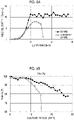
- Fig. 6A is a graph showing transitions in viable cell density (VCD) during a culture period.
- Fig. 6B is a graph showing transitions in cell viability during the culture period.
- VCD viable cell density
- Fig. 6B is a graph showing transitions in cell viability during the culture period.
- the stirring device according to the comparative example was used, the viable cell density and the cell viability decreased sharply on the 16th day after the start of the culture.
- the stirring device according to the embodiment of the disclosed technology neither the viable cell density nor the cell viability decreased sharply.
Landscapes
- Chemical & Material Sciences (AREA)
- Health & Medical Sciences (AREA)
- Life Sciences & Earth Sciences (AREA)
- Organic Chemistry (AREA)
- Engineering & Computer Science (AREA)
- Zoology (AREA)
- Wood Science & Technology (AREA)
- Bioinformatics & Cheminformatics (AREA)
- Genetics & Genomics (AREA)
- Biomedical Technology (AREA)
- General Health & Medical Sciences (AREA)
- Biotechnology (AREA)
- Biochemistry (AREA)
- General Engineering & Computer Science (AREA)
- Microbiology (AREA)
- Sustainable Development (AREA)
- Chemical Kinetics & Catalysis (AREA)
- Cell Biology (AREA)
- Proteomics, Peptides & Aminoacids (AREA)
- Molecular Biology (AREA)
- Immunology (AREA)
- Biophysics (AREA)
- Medicinal Chemistry (AREA)
- Virology (AREA)
- Clinical Laboratory Science (AREA)
- General Chemical & Material Sciences (AREA)
- Apparatus Associated With Microorganisms And Enzymes (AREA)
- Preparation Of Compounds By Using Micro-Organisms (AREA)
- Micro-Organisms Or Cultivation Processes Thereof (AREA)
- Peptides Or Proteins (AREA)
Abstract
Description
- The disclosed technology relates to a cell culture device, a cell culture method, and a production method of a product.
- As technologies relating to a stirring device used for stirring cell suspensions, the following technology is known. For example,
JP2015-147206A - In a large-scale culture in which a large amount (for example, 10 L or more) of a cell suspension is accommodated in a culture vessel and cultured, a stirring culture in which the cells are cultured while stirring the cell suspension is generally applied. Stirring of the cell suspension promotes the supply of oxygen and nutrients to the cells. For stirring the cell suspension, a stirring device having a rotating stirring blade is used. However, in a case where such a stirring device is used, the cells may be damaged by the shear generated by the stirring, which may cause problems such as a decrease in the cell proliferation rate and a decrease in the viability.
- The disclosed technology has been made in view of the above-mentioned points, and an object thereof is to inhibit damage to cells caused by stirring a cell suspension.
- A cell culture device according to the disclosed technology includes: a culture vessel that accommodates a cell suspension containing cells and a culture medium; and a stirring device that is provided at a bottom part of the culture vessel to stir the cell suspension accommodated in the culture vessel. The stirring device has a shaft part; a rotating part that has a hole part into which the shaft part is inserted, and is provided to have a gap of 100 µm or more between an interior wall demarcating the hole part and the shaft part so that the rotation part is rotatable with the shaft part as a rotation axis; and a closing part that closes an end part of the gap in an axial direction of the rotation axis.
- A dimension of the gap is preferably 400 µm or less. The closing part may be provided at one end part of the gap in the axial direction of the rotation axis, or may be provided at both end parts of the gap in the axial direction of the rotation axis. The rotating part may be rotated by a magnetic force. The closing part may be configured to have a packing made of polymer. The culture vessel may have the form of a bag.
- A cell culture method according to the disclosed technology is a cell culture method which uses the above-mentioned cell culture device, the method including culturing cells while stirring a cell suspension accommodated in a culture vessel by rotation of a rotating part.
- The cells are preferably cultured at a shear rate γ [sec-1] defined by Equation (I) in a range of 200 sec-1 or more and 3200 sec-1 or less, in a case where a dimension of a gap is t [µm], and a rotation rate of the rotating part is s [m/sec].

- The culture scheme may be a perfusion culture scheme, or may be a fed-batch scheme. The cells to be cultured may be Chinese Hamster Ovary (CHO) cells.
- A production method of a product according to the disclosed technology is a production method of a product which is for producing a product produced from cells cultured by the above-mentioned cell culture method, the method including a step of collecting a culture medium containing the product from a culture vessel. The product may be an antibody.
- According to the disclosed technology, the damage to cells caused by stirring a cell suspension can be inhibited.
-
-
Fig. 1 is a view showing an example of the configuration of a cell culture device according to the embodiment of the disclosed technology. -
Fig. 2A is a plan view showing an example of the configuration of a stirring device according to the embodiment of the disclosed technology. -
Fig. 2B is a cross-sectional view taken along theline 2B-2B inFig. 2A . -
Fig. 3A is a view showing an example of the internal configuration of a driving unit according to the embodiment of the disclosed technology. -
Fig. 3B is a view showing an example of the internal configuration of a main body of a rotating part according to the embodiment of the disclosed technology. -
Fig. 4A is a view showing another example of the configuration of a closing part according to the embodiment of the disclosed technology. -
Fig. 4B is a view showing still another example of the configuration of the closing part according to the embodiment of the disclosed technology. -
Fig. 4C is a view showing still another example of the configuration of the closing part according to the embodiment of the disclosed technology. -
Fig. 5 is a view showing another example of the configuration of the cell culture device according to the embodiment of the disclosed technology. -
Fig. 6A is a graph showing transitions in viable cell density during a culture period. -
Fig. 6B is a graph showing transitions in cell viability during the culture period. - Hereinafter, an example of the embodiment of the present invention will be described with reference to the drawings. In the respective drawings, the same or equivalent components and portions are denoted by the same reference numerals, and redundant description will be omitted as appropriate.
-
Fig. 1 is a view showing an example of the configuration of acell culture device 100 according to the embodiment of the disclosed technology. Thecell culture device 100 includes aculture vessel 10 accommodating acell suspension 12 containing cells and a culture medium; afilter unit 20 having afilter membrane 24 that applies a membrane separation treatment to the cell suspension extracted from theculture vessel 10; aflow channel 51 through which the cell suspension moving between thefilter unit 20 and theculture vessel 10 passes; aflow channel 53 through which components that have permeated through thefilter membrane 24 passes; and a collectingtank 40 connected to theflow channel 53. Thecell culture device 100 can be suitably used for cell culture by a perfusion culture scheme in which a fresh culture medium is continuously supplied to theculture vessel 10 while a culture medium containing a product such as an antibody is continuously extracted from theculture vessel 10. - The form of the
culture vessel 10 is not particularly limited, but a bag type having the capacity of, for example, 10 L or more, which is used for mass culture of cells, can be preferably used. At the bottom part of theculture vessel 10, astirring device 30 is provided for stirring the cell suspension contained in theculture vessel 10. The detailed configuration of the stirringdevice 30 will be described later. - One end of the
flow channel 51 is inserted into thecell suspension 12, and the other end is connected to a flow port 20a of thefilter unit 20. - The
filter unit 20 includes avessel 21; and afilter membrane 24 that partitions the space inside thevessel 21 into asupply side 22 and apermeation side 23 and applies a membrane separation treatment to thecell suspension 12 extracted from theculture vessel 10. Furthermore, on thesupply side 22, thefilter unit 20 hasflow ports 20a and 20b through which thecell suspension 12 flows. Thecell suspension 12 extracted from theculture vessel 10 flows into the inside of thevessel 21 from the flow port 20a and passes through thefilter membrane 24 until reaching theflow port 20b. Thefilter unit 20 performs a membrane separation treatment by a tangential flow method of pouring a liquid as an object of the membrane separation treatment so as to cause the liquid to flow along the membrane surface of a filter membrane 24 (in a direction parallel to the membrane surface) and sending small-sized components toward thepermeation side 23. - One end of the
flow channel 52 is connected to theflow port 20b, and the other end of theflow channel 52 is connected to a pump PU1. The pump PU1 is a diaphragm pump, for example, and by operating the pump PU1, thecell suspension 12 extracted from theculture vessel 10 forms a reciprocating flow along the membrane surface of thefilter membrane 24. Although not shown in the drawing, for example, by providing a separate flow channel between theculture vessel 10 and the filter unit, the flow channel can be configured such that thecell suspension 12 extracted from theculture vessel 10 forms a flow that circulates in one direction along the membrane surface of thefilter membrane 24. - The cells contained in the
cell suspension 12 do not permeate through thefilter membrane 24, but are returned to theculture vessel 10 via theflow channel 51. On the other hand, the product such as antibodies contained in thecell suspension 12 permeates through thefilter membrane 24, and is discharged to the outside of thevessel 21 through adischarge port 20c provided on thepermeation side 23. On thepermeation side 23, theflow channel 53 provided with a pump PU2 is connected, and a permeation liquid containing the product such as antibodies which has permeated through thepermeation side 23 is collected in the collectingtank 40 via theflow channel 53. - Furthermore, a hollow fiber membrane can be used as the
filter membrane 24. By using a hollow fiber membrane, a risk of cells permeating into the permeation side can be reduced, as compared to the case of using a mesh filter. Also, a risk of the occurrence of clogging caused by cells infiltrating into thefilter membrane 24 can be reduced. Thereby, loss of cells can be reduced. - The product such as antibodies contained in the permeation liquid that has permeated through the
filter membrane 24 and collected in the collectingtank 40 is sent, via aflow channel 56, to a purification treatment unit (not shown in the drawing) in which purification of antibodies is performed. Thecell culture device 100 has aflow channel 54 for supplying a fresh culture medium to theculture vessel 10; and a pump PU3 provided in the middle of theflow channel 54. In order to prevent the concentration of cells in theculture vessel 10 from excessively increasing, a cell bleeding treatment of taking out a portion of cells inside theculture vessel 10 at an appropriate timing during the culture period is carried out. During the cell bleeding treatment, the cells in theculture vessel 10 are discharged to the outside of theculture vessel 10 via aflow channel 55. - The
cell culture device 100 shown inFig. 1 performs a separation treatment by means of the membrane separation treatment using thefilter unit 20; however, it is also possible to replace thefilter unit 20 with a treatment unit of performing a separation treatment according to a sonic agglomeration method. -
Fig. 2A is a plan view showing an example of the configuration of the stirringdevice 30.Fig. 2B is a cross-sectional view taken along theline 2B-2B inFig. 2A . - The stirring
device 30 has apedestal part 31, ashaft part 32, and arotating part 33. Thepedestal part 31 is a plate-shaped member, and is fixed to the bottom surface of theculture vessel 10. Theshaft part 32 is a cylindrical member extending in the direction perpendicular to the surface of thepedestal part 31. Theshaft part 32 may be configured integrally with thepedestal part 31, or may be configured as a separate body from thepedestal part 31. - The
rotating part 33 has amain body 34 and aleaf blade part 35. Themain body 34 has a cylindrical shape having the height as high as the length of theshaft part 32 in the axial direction. Themain body 34 has ahole part 36 penetrating themain body 34 in the center thereof. Theshaft part 32 is inserted into thehole part 36. Themain body 34 can rotate with theshaft part 32 as a rotation axis. A gap (clearance) 37 is secured between the inner wall on the hole part side of the main body (the inner wall demarcating the hole part 36) and theshaft part 32. That is, therotating part 33 is not in contact with theshaft part 32. - The
main body 34 is provided with threeleaf blade parts 35. Theleaf blade part 35 has a portion protruding from the outer edge of themain body 34, and functions as a stirring blade for stirring thecell suspension 12 by rotating with themain body 34. Stirring of thecell suspension 12 promotes the supply of oxygen and nutrients to the cells. The shape of theleaf blade part 35 is not particularly limited, and may be any shape that promotes stirring. Theleaf blade part 35 may be configured integrally with themain body 34, or may be configured as a separate body from themain body 34. Furthermore, the number of theleaf blade parts 35 may be two or less, or may be four or more. - The stirring
device 30 has a closingpart 38 that closes the upper end part of thegap 37 in the axial direction of the rotation axis. The closingpart 38 has the form of a ring shape corresponding to the shape seen from the upper side of thegap 37 in the axial direction. The surface of the closingpart 38 in contact with theshaft part 32 may be adhered to theshaft part 32. In this case, the surface of the closingpart 38 in contact with the inner wall on the hole part side of themain body 34 is slidable with respect to the inner wall on the hole part side of themain body 34. On the other hand, the surface of the closingpart 38 in contact with the inner wall on the hole part side of themain body 34 may be adhered to the inner wall on the hole part side of themain body 34. In this case, the surface of the closingpart 38 in contact with theshaft part 32 is slidable with respect to theshaft part 32. A packing made of polymer can be suitably used as the closingpart 38. During the culture period, the stirringdevice 30 is in a state of being immersed in thecell suspension 12. In a case where the closingpart 38 closes the end part of thegap 37, the inflow of thecell suspension 12 into thegap 37 can be inhibited. The closingpart 38 serves as resistance to the rotation of therotating part 33, but the contact pressure of the sliding surface is adjusted to such an extent that the rotation of therotating part 33 is not hindered. - The
rotating part 33 is rotated by a magnetic force. On the outside of theculture vessel 10, the stirringdevice 30 has a drivingunit 39 installed near therotating part 33.Fig. 3A is a view showing an example of the internal configuration of the drivingunit 39. The drivingunit 39 has a circular surface facing the bottom surface of therotating part 33, and a center point P of this circle is aligned with the position (that is, the rotation axis of the rotating part 33) corresponding to theshaft part 32. The drivingunit 39 has a ring-shapedmagnet 60A having a center point at the center point P, and a plurality ofmagnets 60B disposed radially around the center point P. The plurality ofmagnets 60B are disposed such that the polarities on the side facing therotating part 33 are alternately reversed. The plurality ofmagnets 60B are rotated around the center point P by a motor mechanism (not shown in the drawing). -
Fig. 3B is a view showing an example of the internal configuration of themain body 34 of therotating part 33. Therotating part 33 has a ring-shapedmagnet 70A and a plurality ofmagnets 70B which are configured in the same manner as the drivingunit 39. Themagnet 70A is disposed at the position corresponding to themagnet 60A of the drivingunit 39, and the plurality ofmagnets 70B are disposed at the position corresponding to the plurality ofmagnets 60B of the drivingunit 39. Themagnet 60A and themagnet 70A have the same polarity on the opposite sides (N pole in the present embodiment). Accordingly, repulsive forces act on themagnet 60A and themagnet 70A. Due to this repulsive force, therotating part 33 rises from thepedestal part 31. Furthermore, a force attracting each other acts on themagnet 60B and themagnet 70B. Therefore, with the rotation of themagnet 60B of the drivingunit 39, therotating part 33 rotates with theshaft part 32 as the rotation axis in a state of being levitated from thepedestal part 31. - Here, in a case where the dimension of the
gap 37 is t [µm] and the rotation rate of therotating part 33 is s [m/sec], the shear rate γ [sec-1] acting on thecell suspension 12 that has flowed into thegap 37 by the rotation of therotating part 33 is expressed by Equation (1).
- During the culture period, the shear rate γ is preferably 200 sec-1 or more and 3200 sec-1 or less, more preferably 500 sec-1 or more and 2500 sec-1 or less, and most preferably 600 sec-1 or more and 2000 sec-1. By setting the shear rate γ to 200 sec-1 or more, stirring of the
cell suspension 12 is promoted, which makes it possible to inhibit cell precipitation and cell choking due to insufficient oxygen supply. By setting the shear rate γ to 3200 sec-1 or less, the shear acting on the cells contained in thecell suspension 12 that has flowed into thegap 37 can be inhibited. Accordingly, damage to the cells due to stirring can be inhibited, making it possible to inhibit a deterioration of cell proliferation and viability. - Furthermore, the dimension of the gap 37 (that is, the distance between the surface of the
shaft part 32 and the inner wall of the hole part 36) G is preferably 100 µm or more and 400 µm or less, more preferably 100 µm or more and 300 µm or less, and most preferably 120 µm or more and 200 µm or less. By setting the dimension G of thegap 37 to 100 µm or more, the shearing acting on the cells contained in the cell suspension that has flowed into thegap 37 can be inhibited. By setting the dimension G of thegap 37 to 400 µm or less, the eccentricity of therotating part 33 with respect to theshaft part 32 can be inhibited. Accordingly, an increase in the shear rate due to eccentricity can be inhibited, making it possible to inhibit damage to cells due to shearing. In addition, wear of theshaft part 32 due to eccentricity can be inhibited. - The dimension G can be calculated by (the inner diameter of the main body of the rotating part)/2 - (the diameter of the shaft part)/2.
- Here, in a stirring culture in which a cell suspension is stirred using a rotating stirring blade, it is generally known that the shear generated at the distal end of the stirring blade is a factor of the damage to cells. The inventors of the present invention have found that not only the distal end of the stirring blade but also the shear generated in the
gap 37 formed around the rotation axis of the stirring blade is also a factor of the damage. - The stirring
device 30 according to the embodiment of the disclosed technology has the closingpart 38 that closes the end part, in the axial direction of the rotation axis, of thegap 37 formed between the inner wall on the hole part side of themain body 34 and theshaft part 32. Accordingly, the inflow of thecell suspension 12 into thegap 37 can be inhibited. Therefore, the number of cells damaged by the shear generated in thegap 37 can be reduced. Furthermore, by setting the dimension G of thegap 37 to 100 µm or more, even in a case where thecell suspension 12 flows into thegap 37, the damage to the cells due to the shear generated in thegap 37 can be inhibited. -
Fig. 4A to Fig. 4C are cross-sectional views showing another example of the configuration of the closingpart 38. As shown inFig. 4A , the closingpart 38 may be configured to close the lower end part of thegap 37 in the axial direction of the rotation axis. The inflow of thecell suspension 12 into thegap 37 can be inhibited also by closing the lower end part of thegap 37 as above. - Furthermore, as shown in
Fig. 4B , the closingpart 38 may be configured to close both end parts of thegap 37 in the axial direction of the rotation axis. This makes it possible to substantially and completely prevent the inflow of thecell suspension 12 into thegap 37. - Furthermore, as shown in
Fig. 4C , closing of the end part of thegap 37 in the axial direction of the rotation axis may be performed by theclosing parts closing part 38A is attached to the inner wall of thehole part 36, and theclosing part 38B is attached to the surface of theshaft part 32. Theclosing part 38A and theclosing part 38B are disposed at positions where their sliding surfaces are in contact with each other. By closing the end parts of thegap 37 with theclosing parts gap 37 can be improved. -
Fig. 5 is a view showing an example of the configuration of acell culture device 100A according to another embodiment of the disclosed technology. Thecell culture device 100A is configured to include aculture vessel 10, a stirringdevice 30, aflow channel 54, and a pump PU3. Thecell culture device 100A does not include thefilter unit 20, the collectingtank 40, and theflow channel 55 for performing the cell bleeding treatment, which are provided in thecell culture device 100 shown inFig. 1 . Thecell culture device 100A can be suitably used for cell culture by the fed-batch scheme. The cell culture by the fed-batch scheme is a scheme in which a fresh culture medium is added to theculture vessel 10 at a predetermined timing without extracting thecell suspension 12 accommodated in theculture vessel 10 during the culture period. Even in the case of performing the cell culture by the fed-batch scheme, by providing the stirringdevice 30 to which the disclosed technology has been applied, the damage to cells due to stirring of thecell suspension 12 can be inhibited. - A cell culture method according to the embodiment of the disclosed technology uses the cell culture device 100 (refer to
Fig. 1 ) or 100A (refer toFig. 5 ), in which culture of cells is performed while stirring thecell suspension 12 accommodated in theculture vessel 10 by rotating therotating part 33 of the stirringdevice 30. By using the cell culture device 100 (refer toFig. 1 ), cell culture by the perfusion culture scheme can be performed. By using thecell culture device 100A (refer toFig. 5 ), cell culture by the fed-batch scheme can be performed. - The cells cultured using the
cell culture device 100 or thecell culture device 100A are not particularly limited, but are preferably cells that produce a product. The cells used as the cells that produce a product are not particularly limited; however, examples include eukaryotic cells such as animal cells, plant cells, and yeasts; prokaryotic cells such as Bacillus subtilis; and Escherichia coli. Animal cells such as CHO cells, BHK-21 cells, and SP2/0-Ag14 cells are preferred, and CHO cells are more preferred. Furthermore, the product produced from the cells is not particularly limited as long as it is a substance that the above-mentioned cells produce in the culture medium, and examples thereof alcohols, enzymes, antibiotic substances, recombinant proteins, and antibodies, where recombinant proteins and antibodies are preferable, and antibodies are more preferable. - An antibody produced by an animal cell is not particularly limited; however, examples include an anti-IL-6 receptor antibody, an anti-IL-6 antibody, an anti-glypican-3 antibody, an anti-CD3 antibody, an anti-CD20 antibody, an anti-GPIIb/IIIa antibody, an anti-TNF antibody, an anti-CD25 antibody, an anti-EGFR antibody, an anti-Her2/neu antibody, an anti-RSV antibody, an anti-CD33 antibody, an anti-CD52 antibody, an anti-IgE antibody, an anti-CD11a antibody, an anti-VEGF antibody, and an anti-VLA4 antibody. Examples of the antibodies include monoclonal antibodies derived from animals such as human being, mouse, rat, hamster, rabbit, and monkey, as well as artificially modified antibodies such as a chimeric antibody, a humanized antibody, and a bispecific antibody.
- By rotating the
rotating part 33 of the stirringdevice 30 during the culture period, stirring of thecell suspension 12 is promoted, which promotes the supply of oxygen and nutrients to the cells. Regarding the rotation rate s of therotating part 33, the rotation rate of therotating part 33 is preferably controlled such that the shear rate γ defined by Equation (1) is 200 sec-1 or more and 3200 sec-1 or less. The rotation rate of therotating part 33 may be constant, or may be changed according to the culture state such as cell density or the elapsed time from the start of culture. - A production method of a product according to the embodiment of the disclosed technology is a method of producing a product produced from the cells cultured by the above-mentioned culture method, the production method including a step of collecting a culture medium containing the product from the
culture vessel 10. The product is preferably an antibody. By culturing, for example, CHO cells in theculture vessel 10, an antibody produced from the CHO cells can be obtained. - In a case where the
cell culture device 100 shown inFig. 1 is used, the product such as antibodies can be collected in the collectingtank 40. In a case where thecell culture device 100A shown inFig. 5 is used, the product such as antibodies can be collected together with thecell suspension 12 accommodated in theculture vessel 10. - The antibody thus obtained or a fragment thereof can be purified until the antibody or the fragment becomes approximately uniform. Separation and purification of the antibody or a fragment thereof may be carried out using conventional separation and purification methods used for general polypeptides. For example, in a case in which a column for chromatography such as affinity chromatography, a filter, ultrafiltration, salting out, dialysis, SDS polyacrylamide gel electrophoresis, and isoelectric point electrophoresis are selected as appropriate and combined, the antibody can be separated and purified; however, the methods are not limited to these. Measurement of the concentration of the antibody thus obtained can be carried out by measurement of the absorbance, an enzyme-linked immunosorbent assay (ELISA), or the like.
- Cell culture was performed by the perfusion culture scheme using the
cell culture device 100 having the configuration shown inFig. 1 . CHO cells were used as cells to be cultured. As theculture vessel 10, a single-use bag-type vessel having the capacity of 10 L was used. The seeding density of the cells was 3 × 10⁵ cells/mL. The supply of a fresh culture medium and the extraction of the cell suspension from theculture vessel 10 were performed after the third day from the start of the culture. Cell bleeding treatment was appropriately performed so that the cell density was maintained at about 110 × 106 cells/ml during the culture period. The rotation rate of therotating part 33 of the stirringdevice 30 was set to 200 rpm from the start of the culture to the 10th day, and 240 rpm after the 10th day. During the culture period, air having the flow rate of 0.1 L/min was supplied from the upper surface in theculture vessel 10. Pure oxygen was supplied from a 20 µm sparger disposed at the bottom part of theculture vessel 10 so that the oxygen concentration in the cell suspension in theculture vessel 10 was 33%. - As a stirring device for stirring the cell suspension, the one in Table 1 below was used. That is, as the stirring device according to the embodiment of the disclosed technology, a stirring device which had a closing part having the configuration shown in
Fig. 4C and in which the dimension G of thegap 37 was 150 µm was used. In this case, the inner diameter of the main body of the rotating part was 15900 µm, and the diameter of the shaft part was 15600 µm. According to the stirring device according to the embodiment of the disclosed technology, the shear rate γ in thegap 37 is 1109 s-1 from the start of the culture to the 10th day, and 1331 s-1 after the 10th day. Furthermore, as a stirring device according to a comparative example, a stirring device which had no closing part and in which the dimension G of thegap 37 was 50 µm was used. In this case, the inner diameter of the main body of the rotating part was 15800 µm, and the diameter of the shaft part was 15700 µm. According to the stirring device according to the comparative example, the shear rate γ in thegap 37 is 3307 s-1 from the start of the culture to the 10th day, and 3968 s-1 after the 10th day.[Table 1] Closing part Dimension G of gap Shear rate γ Example Provided 150 µm Until day 10: 1109 s-1 From day 10: 1331 s-1 Comparative Example Not provided 50 µm Until day 10: 3307 s-1 From day 10: 3968 s-1 -
Fig. 6A is a graph showing transitions in viable cell density (VCD) during a culture period.Fig. 6B is a graph showing transitions in cell viability during the culture period. In a case where the stirring device according to the comparative example was used, the viable cell density and the cell viability decreased sharply on the 16th day after the start of the culture. On the other hand, in a case where the stirring device according to the embodiment of the disclosed technology was used, neither the viable cell density nor the cell viability decreased sharply. It is thought that this is because the inflow of the cell suspension into thegap 37 is inhibited by the closing part, and even in a case where the cells flow into thegap 37, the shear rate γ in thegap 37 is limited by the optimization of the dimension G of thegap 37, thereby restraining the damage to the cells. - The disclosure of
Japanese Patent Application No. 2020-048440 filed on March 18, 2020
Claims (14)
- A cell culture device comprising:a culture vessel that accommodates a cell suspension containing cells and a culture medium; anda stirring device that is provided at a bottom part of the culture vessel to stir the cell suspension accommodated in the culture vessel,wherein the stirring device hasa shaft part,a rotating part that has a hole part into which the shaft part is inserted, and is provided to have a gap of 100 µm or more between an interior wall demarcating the hole part and the shaft part so that the rotation part is rotatable with the shaft part as a rotation axis, anda closing part that closes an end part of the gap in an axial direction of the rotation axis.
- The cell culture device according to claim 1,
wherein a dimension of the gap is 400 µm or less. - The cell culture device according to claim 1 or 2,
wherein the closing part is provided at one end part of the gap in the axial direction of the rotation axis. - The cell culture device according to claim 1 or 2,
wherein the closing part is provided at both end parts of the gap in the axial direction of the rotation axis. - The cell culture device according to any one of claims 1 to 4,
wherein the rotating part is rotated by a magnetic force. - The cell culture device according to any one of claims 1 to 5,
wherein the closing part is configured to have a packing made of polymer. - The cell culture device according to any one of claims 1 to 6,
wherein the culture vessel has the form of a bag. - A cell culture method which uses the cell culture device according to any one of claims 1 to 7, the method comprising culturing cells while stirring a cell suspension accommodated in a culture vessel by rotation of a rotating part.
- The cell culture method according to claim 8,
wherein the cells are cultured at a shear rate γ [sec-1] defined by Equation (I) in a range of 200 sec-1 or more and 3200 sec-1 or less, in a case where a dimension of a gap is t [µm], and a rotation rate of the rotating part is s [m/sec],
- The cell culture method according to claim 8 or 9,
wherein the cells are cultured by a perfusion culture scheme. - The cell culture method according to claim 8 or 9,
wherein the cells are cultured by a fed-batch scheme. - The cell culture method according to any one of claims 8 to 11,
wherein the cells are CHO cells. - A production method of a product,wherein a product produced from cells cultured by the cell culture method according to any one of claims 8 to 12 is produced,the method comprising a step of collecting a culture medium containing the product from the culture vessel.
- The production method according to claim 13,
wherein the product is an antibody.
Applications Claiming Priority (2)
| Application Number | Priority Date | Filing Date | Title |
|---|---|---|---|
| JP2020048440 | 2020-03-18 | ||
| PCT/JP2021/006423 WO2021187008A1 (en) | 2020-03-18 | 2021-02-19 | Cell culturing device, cell culturing method, and method for producing product |
Publications (2)
| Publication Number | Publication Date |
|---|---|
| EP4101922A1 true EP4101922A1 (en) | 2022-12-14 |
| EP4101922A4 EP4101922A4 (en) | 2023-08-16 |
Family
ID=77771292
Family Applications (1)
| Application Number | Title | Priority Date | Filing Date |
|---|---|---|---|
| EP21771343.7A Pending EP4101922A4 (en) | 2020-03-18 | 2021-02-19 | Cell culturing device, cell culturing method, and method for producing product |
Country Status (4)
| Country | Link |
|---|---|
| US (1) | US20220403308A1 (en) |
| EP (1) | EP4101922A4 (en) |
| JP (1) | JP7499844B2 (en) |
| WO (1) | WO2021187008A1 (en) |
Families Citing this family (4)
| Publication number | Priority date | Publication date | Assignee | Title |
|---|---|---|---|---|
| EP4653538A1 (en) | 2023-01-17 | 2025-11-26 | FUJIFILM Corporation | Method for producing nucleic acid introduced cells, and method for producing useful substance |
| WO2024204415A1 (en) | 2023-03-27 | 2024-10-03 | 富士フイルム株式会社 | Virus production method |
| WO2025047766A1 (en) | 2023-08-29 | 2025-03-06 | 富士フイルム株式会社 | Virus production method and method for introducing nucleic acid into cell |
| WO2025070513A1 (en) | 2023-09-27 | 2025-04-03 | 富士フイルム株式会社 | Apparatus and method for treating cell culture solution, and method for producing product |
Family Cites Families (14)
| Publication number | Priority date | Publication date | Assignee | Title |
|---|---|---|---|---|
| GB8530510D0 (en) * | 1985-12-11 | 1986-01-22 | Chem Plant Stainless Ltd | Vessel |
| GB8625509D0 (en) * | 1986-10-24 | 1986-11-26 | Horseman C J | Driving mixers & pumps |
| CA2552717C (en) * | 2004-01-07 | 2011-11-29 | Levtech, Inc. | Mixing bag with integral sparger and sensor receiver |
| JP2006296423A (en) * | 2005-03-24 | 2006-11-02 | Hitachi Ltd | Culture tank control device and culture device |
| US7503745B2 (en) * | 2005-09-19 | 2009-03-17 | Grindmaster Corporation | Pump assembly for chilled beverage dispenser |
| WO2013040161A1 (en) * | 2011-09-16 | 2013-03-21 | Xcellerex, Inc. | Single-use mixing and bioreactor systems |
| US9574165B2 (en) * | 2012-06-11 | 2017-02-21 | Able Corporation | Cell culture apparatus and cell culture method using the same |
| DE102013104788A1 (en) * | 2013-05-08 | 2014-11-13 | Liquitec Ag | magnetic stirrer |
| US9880067B2 (en) * | 2013-12-03 | 2018-01-30 | Pall Corporation | Mechanical agitator with seal housing assembly |
| US9248420B2 (en) | 2013-12-16 | 2016-02-02 | Pall Corporation | High turndown impeller |
| KR20230156168A (en) * | 2015-08-08 | 2023-11-13 | 스토베 게엠베하 | Disposable bioprocess system supporting biological activity |
| JP6374929B2 (en) * | 2016-09-29 | 2018-08-15 | 佐竹化学機械工業株式会社 | Agitation culture equipment |
| EP3770266A4 (en) * | 2018-03-19 | 2021-06-09 | FUJIFILM Corporation | PRODUCT PRODUCTION METHOD |
| JP7249753B2 (en) | 2018-09-25 | 2023-03-31 | サッポロビール株式会社 | Alcoholic beverage, method for producing alcoholic beverage, and method for enhancing oil sharpness |
-
2021
- 2021-02-19 EP EP21771343.7A patent/EP4101922A4/en active Pending
- 2021-02-19 JP JP2022508155A patent/JP7499844B2/en active Active
- 2021-02-19 WO PCT/JP2021/006423 patent/WO2021187008A1/en not_active Ceased
-
2022
- 2022-08-22 US US17/892,655 patent/US20220403308A1/en active Pending
Also Published As
| Publication number | Publication date |
|---|---|
| JP7499844B2 (en) | 2024-06-14 |
| EP4101922A4 (en) | 2023-08-16 |
| WO2021187008A1 (en) | 2021-09-23 |
| JPWO2021187008A1 (en) | 2021-09-23 |
| US20220403308A1 (en) | 2022-12-22 |
Similar Documents
| Publication | Publication Date | Title |
|---|---|---|
| US20220403308A1 (en) | Cell culture device, cell culture method, and production method of product | |
| US12049614B2 (en) | Cell culture apparatus and cell culture method | |
| CN111868249B (en) | Method for producing product | |
| KR102539167B1 (en) | Alternating tangential flow rapid harvesting | |
| US11685888B2 (en) | Method for producing product | |
| US8679778B2 (en) | Method for producing a biopolymer (e.g. polypeptide) in a continuous fermentation process | |
| US20210147781A1 (en) | Cell culture method, product producing method, and cell culture device | |
| EP1354941A1 (en) | Apparatus and method for a cell culture in a bioreactor at high cell concentration | |
| WO2017180724A1 (en) | Perfusion filtration systems | |
| US8852435B2 (en) | Purification and separation treatment assembly (PASTA) for biological products | |
| US20160083685A1 (en) | Harvesting and purification or perfusion yielder (happy) device | |
| RU2710967C9 (en) | Method for detachable-topping fermentation with high cell density | |
| Blasey et al. | Strategies to increase the efficiency of membrane aerated and perfused animal cell bioreactors by an improved medium perfusion | |
| US20020170831A1 (en) | Apparatus and method for separation of molecules and movement of fluids | |
| US20230235263A1 (en) | Systems and methods for filtration of cell cultures | |
| WO2025155633A1 (en) | Perfusion cell culture systems and methods |
Legal Events
| Date | Code | Title | Description |
|---|---|---|---|
| STAA | Information on the status of an ep patent application or granted ep patent |
Free format text: STATUS: THE INTERNATIONAL PUBLICATION HAS BEEN MADE |
|
| PUAI | Public reference made under article 153(3) epc to a published international application that has entered the european phase |
Free format text: ORIGINAL CODE: 0009012 |
|
| STAA | Information on the status of an ep patent application or granted ep patent |
Free format text: STATUS: REQUEST FOR EXAMINATION WAS MADE |
|
| 17P | Request for examination filed |
Effective date: 20220906 |
|
| AK | Designated contracting states |
Kind code of ref document: A1 Designated state(s): AL AT BE BG CH CY CZ DE DK EE ES FI FR GB GR HR HU IE IS IT LI LT LU LV MC MK MT NL NO PL PT RO RS SE SI SK SM TR |
|
| DAV | Request for validation of the european patent (deleted) | ||
| DAX | Request for extension of the european patent (deleted) | ||
| A4 | Supplementary search report drawn up and despatched |
Effective date: 20230714 |
|
| RIC1 | Information provided on ipc code assigned before grant |
Ipc: C12P 21/08 20060101ALI20230710BHEP Ipc: C12N 15/13 20060101ALI20230710BHEP Ipc: C12N 5/07 20100101ALI20230710BHEP Ipc: C07K 16/00 20060101ALI20230710BHEP Ipc: C12M 3/02 20060101AFI20230710BHEP |