EP4101794A1 - Specimen transport system and specimen transport method - Google Patents
Specimen transport system and specimen transport method Download PDFInfo
- Publication number
- EP4101794A1 EP4101794A1 EP21750712.8A EP21750712A EP4101794A1 EP 4101794 A1 EP4101794 A1 EP 4101794A1 EP 21750712 A EP21750712 A EP 21750712A EP 4101794 A1 EP4101794 A1 EP 4101794A1
- Authority
- EP
- European Patent Office
- Prior art keywords
- transport
- specimen
- detection
- detection range
- holder
- Prior art date
- Legal status (The legal status is an assumption and is not a legal conclusion. Google has not performed a legal analysis and makes no representation as to the accuracy of the status listed.)
- Granted
Links
Images




Classifications
-
- B—PERFORMING OPERATIONS; TRANSPORTING
- B65—CONVEYING; PACKING; STORING; HANDLING THIN OR FILAMENTARY MATERIAL
- B65G—TRANSPORT OR STORAGE DEVICES, e.g. CONVEYORS FOR LOADING OR TIPPING, SHOP CONVEYOR SYSTEMS OR PNEUMATIC TUBE CONVEYORS
- B65G54/00—Non-mechanical conveyors not otherwise provided for
- B65G54/02—Non-mechanical conveyors not otherwise provided for electrostatic, electric, or magnetic
-
- G—PHYSICS
- G01—MEASURING; TESTING
- G01N—INVESTIGATING OR ANALYSING MATERIALS BY DETERMINING THEIR CHEMICAL OR PHYSICAL PROPERTIES
- G01N35/00—Automatic analysis not limited to methods or materials provided for in any single one of groups G01N1/00 - G01N33/00; Handling materials therefor
- G01N35/02—Automatic analysis not limited to methods or materials provided for in any single one of groups G01N1/00 - G01N33/00; Handling materials therefor using a plurality of sample containers moved by a conveyor system past one or more treatment or analysis stations
- G01N35/04—Details of the conveyor system
-
- H—ELECTRICITY
- H02—GENERATION; CONVERSION OR DISTRIBUTION OF ELECTRIC POWER
- H02K—DYNAMO-ELECTRIC MACHINES
- H02K41/00—Propulsion systems in which a rigid body is moved along a path due to dynamo-electric interaction between the body and a magnetic field travelling along the path
- H02K41/02—Linear motors; Sectional motors
- H02K41/03—Synchronous motors; Motors moving step by step; Reluctance motors
-
- G—PHYSICS
- G01—MEASURING; TESTING
- G01N—INVESTIGATING OR ANALYSING MATERIALS BY DETERMINING THEIR CHEMICAL OR PHYSICAL PROPERTIES
- G01N35/00—Automatic analysis not limited to methods or materials provided for in any single one of groups G01N1/00 - G01N33/00; Handling materials therefor
- G01N35/02—Automatic analysis not limited to methods or materials provided for in any single one of groups G01N1/00 - G01N33/00; Handling materials therefor using a plurality of sample containers moved by a conveyor system past one or more treatment or analysis stations
- G01N35/04—Details of the conveyor system
- G01N2035/0401—Sample carriers, cuvettes or reaction vessels
- G01N2035/0406—Individual bottles or tubes
-
- G—PHYSICS
- G01—MEASURING; TESTING
- G01N—INVESTIGATING OR ANALYSING MATERIALS BY DETERMINING THEIR CHEMICAL OR PHYSICAL PROPERTIES
- G01N35/00—Automatic analysis not limited to methods or materials provided for in any single one of groups G01N1/00 - G01N33/00; Handling materials therefor
- G01N35/02—Automatic analysis not limited to methods or materials provided for in any single one of groups G01N1/00 - G01N33/00; Handling materials therefor using a plurality of sample containers moved by a conveyor system past one or more treatment or analysis stations
- G01N35/04—Details of the conveyor system
- G01N2035/0474—Details of actuating means for conveyors or pipettes
- G01N2035/0477—Magnetic
-
- G—PHYSICS
- G01—MEASURING; TESTING
- G01N—INVESTIGATING OR ANALYSING MATERIALS BY DETERMINING THEIR CHEMICAL OR PHYSICAL PROPERTIES
- G01N35/00—Automatic analysis not limited to methods or materials provided for in any single one of groups G01N1/00 - G01N33/00; Handling materials therefor
- G01N35/02—Automatic analysis not limited to methods or materials provided for in any single one of groups G01N1/00 - G01N33/00; Handling materials therefor using a plurality of sample containers moved by a conveyor system past one or more treatment or analysis stations
- G01N35/04—Details of the conveyor system
- G01N2035/0474—Details of actuating means for conveyors or pipettes
- G01N2035/0491—Position sensing, encoding; closed-loop control
Definitions
- the present invention relates to a specimen transport system and a specimen transport method in a specimen analysis device that analyzes a biological sample (hereinafter, referred to as a specimen) such as blood, plasma, serum, urine, and other body fluid, or a specimen pretreatment device that performs a pretreatment necessary for analysis.
- a specimen a biological sample
- a specimen pretreatment device that performs a pretreatment necessary for analysis.
- PTL 1 discloses a laboratory sample delivery system including several container carriers, each of the container carriers including at least one magnetically active device, preferably at least one permanent magnet and being adapted to transport a sample container, a transport plane adapted to transport the container carriers, and several electromagnetic actuators disposed to be stationary below the transport plane and adapted to move the container carriers on the transport plane by applying a magnetic force to the container carriers.
- PTL 2 describes an inspection chamber sample distribution system including a transfer surface, a plurality of sample container carriers, a drive unit configured to move the sample container carriers on the transfer surface, and a control device configured to control the movement of the sample container carriers on the transfer surface by driving the drive unit such that the sample container carriers move along a corresponding transfer path.
- a plurality of optically recognizable geometric shapes are placed on the transfer surface, and each of the geometric shapes represents a dedicated field on the transfer surface.
- specimen treatment system for automatically analyzing a specimen which is a biological sample such as blood or urine
- specimen pretreatment system that performs input, centrifugation, dispensing, labeling, and the like of a specimen
- automatic analysis system that analyzes a specimen treated by such a specimen pretreatment system.
- Specimen pretreatment systems and automatic analysis systems in the related art include a specimen transport line using a belt conveyor or the like in order to transport a specimen to a mechanism that performs a predetermined treatment and analysis. By mounting a plurality of such transport lines on the specimen transport system, the specimen is transported to a predetermined mechanism.
- PTL 1 discloses the laboratory sample delivery system that is very flexible and gives high transport performance.
- PTL 2 discloses that a position sensor that detects a position of a permanent magnet installed in a holder on which a specimen vessel containing a specimen is mounted is provided, and by transporting the holder by exciting an electromagnetic actuator corresponding to a direction in which the specimen is to be transported according to position information detected by the position sensor, the specimen is transported to a desired position.
- the holder In a specimen transport system using an electromagnetic actuator, as described in PTL 2, after the position information of the specimen is detected, the holder is transported by exciting the electromagnetic actuator existing in the direction in which the specimen is to be transported. By repeating this operation, the holder is transported to a predetermined position.
- collisions between the holders or erroneous detection of an adjacent holder may occur when accurate position information is not detected.
- the position sensor is used for detecting the position information of the specimen, but a detection range of the position sensor is not considered. It has become clear by the study of the present inventors that it is necessary to improve a detection accuracy for the holder in implementing the specimen transport at higher speed and higher accuracy.
- the invention provides a specimen transport system and a specimen transport method that support a transport method using an electromagnetic actuator and can transport a specimen at higher speed and more stably as compared to the related art.
- the invention includes a plurality of means for solving the above problems, and an example thereof is a specimen transport system that transports a specimen mounted on a specimen holder by sliding on a transport path by an interaction between a magnetic body and an electromagnet provided in the specimen holder.
- the specimen transport system includes a plurality of detection points each configured by the electromagnet and detecting a position of the magnetic body, and a plurality of transport paths provided above the plurality of detection points so as to cover the plurality of detection points.
- a detection range at a first detection point constituting a first transport path is different from a detection range at a second detection point constituting a second transport path different from the first transport path, among the plurality of transport paths.
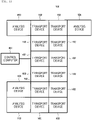
- Fig. 1 is a plan view showing a configuration of the entire specimen transport system according to Example 1 of the invention.
- a specimen transport system 100 according to Example 1 shown in Fig. 1 is a system provided with an analysis device for automatically analyzing components of a specimen such as blood or urine.
- Main components of the specimen transport system 100 include a holder 202 (see Fig. 2 ) on which a specimen vessel 201 (see Fig. 2 ) containing a specimen such as blood or urine is mounted, or a plurality of (12 in Fig. 1 ) transport devices 102 that transport an empty holder, a plurality of (4 in Fig. 1 ) analysis devices 103, and a control computer 101 that integrally manages the specimen transport system 100.
- the analysis device 103 is a unit for performing qualitative and quantitative analysis of components of a specimen transported by the transport device 102. Analysis items in this unit are not particularly limited, and a configuration of a known automatic analysis device that analyzes biochemical items and immune items can be adopted. Further, when a plurality of analysis devices 103 are provided, the analysis devices 103 may have the same specifications or different specifications, and the specifications are not particularly limited.
- Each of the transport devices 102 is a device that transports a specimen mounted on the holder 202 to a destination by sliding on a transport path by an interaction between a magnetic body 203 (see Fig. 2 ) provided on the holder 202 and magnetic poles 207 (see Fig. 2 ). The details will be described with reference to Fig. 2 and the subsequent drawings.
- the control computer 101 controls an operation of the entire system including the transport devices 102 and the analysis devices 103, and is implemented by a computer including a display device such as a liquid crystal display, an input device, a storage device, a CPU, a memory, and the like.
- the control of the operation of each device by the control computer 101 is executed based on various programs recorded in the storage device.
- a control processing for the operation executed by the control computer 101 may be integrated into one program, may be divided into a plurality of programs, or may be a combination thereof.
- a part or all of the programs may be implemented by dedicated hardware or may be modularized.
- detection ranges 301A, 301B, and 301C at a plurality of detection points are determined for each setting of transport of the holder 202 to the analysis device 103. The details thereof will be described later.
- Fig. 1 the case where four analysis devices 103 are provided is described, and the number of the analysis devices is not particularly limited and may be one or more. Similarly, the number of the transport devices 102 is not particularly limited and may be one or more.
- the specimen transport system 100 can be provided with various specimen pretreatment and post-treatment units that perform pretreatment and post-treatment on a specimen.
- a detailed configuration of the specimen pretreatment and post-treatment units is not particularly limited, and a configuration of a known pretreatment device can be adopted.
- Fig. 2 is a configuration diagram showing an outline of the transport device 102.
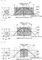
- Fig. 3 is a diagram showing an example of a current change curve obtained in the transport device.
- Figs. 4 to 6 are schematic diagrams each showing an example of a method of setting a detection range in the transport device.
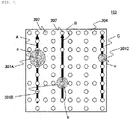
- Fig. 7 is a diagram showing a state of a partial upper surface of the transport device.
- a plurality of holders 202 on which the specimen vessel 201 containing a specimen is installed are provided in the transport device 102.
- the magnetic body 203 is provided on a bottom surface portion of each of the plurality of holders 202.
- the magnetic body 203 is formed of, for example, a permanent magnet such as neodymium or ferrite.
- the magnetic body 203 can also be formed of other magnets and soft magnetic bodies, and can be formed of appropriate combinations thereof.
- the magnetic body 203 is preferably provided on the lower surface from the viewpoint of efficiently applying a transport force of electromagnetic transport.
- the holder 202 including the magnetic body 203 moves in a sliding manner on a transport surface 204.
- a plurality of magnetic poles 207 each including a cylindrical core 205 and a winding 206 wound around an outer periphery of the core 205 are provided below the transport surface 204.
- the magnetic poles 207 constitute the plurality of detection points for detecting a position of the magnetic body 203.
- a plurality of transport paths are provided above the magnetic poles 207 so as to cover the magnetic poles 207.
- the plurality of magnetic poles 207 provided therein are used to detect the position of the magnetic body 203 and are also used to transport the magnetic body 203, that is, to transport a specimen.
- specifications of the magnetic poles 207 in the transport device 102 are the same for all the magnetic poles 207, but the specifications are not necessarily the same.
- the magnetic pole 207 is connected to a drive unit 208 that applies a predetermined voltage to the magnetic pole 207 to cause a predetermined current to flow through the winding 206.
- the magnetic pole 207 to which the voltage is applied by the drive unit 208 acts as an electromagnet, and attracts the magnetic body 203 in the holder 202 on the transport surface 204.
- the voltage applied to the magnetic pole 207 by the drive unit 208 is stopped, and the voltage is applied by the drive unit 208 to a different magnetic pole 207 adjacent to the magnetic pole 207 in the same manner as described above, so that the magnetic body 203 in the holder 202 is attracted to the adjacent magnetic pole 207.
- This procedure is repeated for all the magnetic poles 207 constituting the transport paths to transport a specimen contained in the specimen vessel 201, which is held by the holder 202 provided with the magnetic body 203, to a destination.
- the current flowing through the winding 206 of the magnetic pole 207 in transport is detected by a current detection unit 209.
- the current flowing through the winding 206 of the magnetic pole 207 detected by the current detection unit 209 is sent to a calculation unit 210 to be digitized, and a current change amount curve 211 depending on a position of a specimen holder as shown in Fig. 3 is acquired.
- a current change amount curve 211 depending on a position of the holder 202 By acquiring the current change amount curve 211 depending on a position of the holder 202, the position of the holder 202 can be detected.
- the calculation unit 210 specifies, based on a command from the control computer 101, a position of a specimen based on the current change amount curve 211.
- the position detection processing may be executed by the calculation unit 210 or the control computer 101, and in the present example, various settings during the position detection are determined in the control computer 101 and executed by the calculation unit 210.
- the calculation unit 210 calculates the current flowing through each of the windings 206 using various kinds of information such as position information, speed information, and weight information of the holder 202, and outputs a command signal to the drive unit 208.
- the drive unit 208 applies a voltage to the corresponding winding 206 based on the command signal.
- thresholds 302A, 302B, and 302C for calculating the position of the magnetic body 203 by obtaining the current change amount curve 211 based on a current value detected by the current detection unit 209 are set to different values for the transport paths, so that a range in which the position of the holder 202 is specified is different for the transport paths.
- the detection determination threshold 302A is set to be smaller than the detection determination thresholds 302B and 302C described later.
- an intersection distance A'-A" between the current change amount curve 211 and a straight line of the detection determination threshold 302A is longer, and the detection range 301A can be set wider than the detection ranges 301B and 301C described later.
- the detection determination threshold 302B is set to a value larger than the detection determination threshold 302A and smaller than the detection determination threshold 302C.
- an intersection distance B'-B" between the current change amount curve 211 and a straight line of the detection determination threshold 302B is shorter than the intersection distance A'-A" between the current change amount curve 211 and the straight line of the detection determination threshold 302A, and it is possible to set the detection range 301B narrower than the detection range 301A at the magnetic pole 207 belonging to the transport path A and wider than the detection range 301C at the magnetic pole 207 belonging to a transport path C.
- the detection determination threshold 302C is set to a value larger than the detection determination thresholds 302A and 302B as in the above cases. Accordingly, an intersection distance C'-C" between the current change amount curve 211 and a straight line of the detection determination threshold 302C is shorter than the intersection distance A'-A" and the intersection distance B'-B", and it is possible to set the detection range 301C narrower than the detection range 301A of the magnetic pole 207 belonging to the transport path A and the detection range 301B of the magnetic pole 207 belonging to the transport path B.
- the plurality of magnetic poles 207 disposed are configured such that the position of the holder 202 can be specified individually in any of the detection ranges 301A, 301B, and 301C.
- any of the detection ranges 301A, 301B, and 301C preferably overlaps the others of detection ranges 301A, 301B, and 301C. Accordingly, the holder 202 can be prevented from being lost as much as possible as the holder 202 is positioned in a narrow carry-out range, and it is possible to achieve more stable transport.
- Each of the detection range 301A at the position a, the detection range 301B at the position b, and the detection range 301C at the position c is not necessarily fixed all the times during the transport of a specimen, and even at the same position, the detection range 301A, the detection range 301B, and the detection range 301C can be changed as needed according to a transport situation.
- the detection ranges 301A, 301B, and 301C can be changed according to the setting of the transport of the holder 202, more specifically, according to a transport speed or a transport density of the magnetic poles 207. This enables stable speed control and avoidance of erroneous detection and collision of the holder 202.
- the values of the detection determination thresholds 302A, 302B, and 302C can be set according to a command signal for setting change from the control computer 101.
- the detection range is set to three types of large, medium, and small has been described, and the detection range may be set to at least two types or more, and may be set to four types or more.
- setting of two types or four or more types of detection ranges can be implemented in the specimen transport system 100 or the transport device 102 by changing the value of the detection determination threshold in each of the detection ranges, as in Figs. 4 to 6 .
- the embodiment in which the detection range setting is changed by changing the detection determination thresholds 302A, 302B, and 302C has been described, and the detection ranges 301A, 301B, and 301C can be set to different ranges for respective transport paths by changing a period of a pulse voltage for position detection applied to the magnetic pole 207 by the drive unit 208.
- the period of the applied pulse voltage is lengthened, and when it is desired to narrow the range, the period is shortened.
- Such a change in the period of the pulse voltage applied to the magnetic pole 207 can also be made according to a command signal for setting change from the control computer 101, as in the case of setting the detection determination thresholds 302A, 302B, and 302C.
- the specimen transport system 100 includes a plurality of detection points each formed of the magnetic pole 207 and configured to detect a position of the magnetic body 203, and the plurality of transport paths A, B, and C provided above the plurality of detection points so as to cover the plurality of detection points.
- a detection range at a first detection point constituting a first transport path is different from a detection range at a second detection point constituting a second transport path different from the first transport path.
- the position of the holder 202 can be obtained at higher speed and more stably as compared to the related art without providing a mechanism that detects the holder 202 on the transport surface 204.
- the detection ranges 301A, 301B, and 301C at the first detection point and the second detection point are different from each other based on the setting of the transport of a specimen, it is possible to set a detection range suitable for implementing the transport according to situations and plans of analysis of the specimen, and it is possible to implement further stable specimen transport at higher speed.
- the detection ranges 301A, 301B, and 301C are different from each other due to a difference in the transport density or a difference in the transport speed of the holder 202, it is possible to prevent transport trouble such as contact between the holders 202 as compared to the related art, and thus it is possible to implement further stable specimen transport.
- the analysis device 103 that analyzes a specimen and the control computer 101 that controls the detection points and an operation of the analysis device 103 are further provided.
- the control computer 101 determines the detection ranges 301A, 301B, and 301C of the plurality of detection points for each setting of transport of the holder 202 to the analysis device 103, so that even during the analysis of a specimen, it is possible to set a detection range suitable for implementing the transport according to situations and plans of analysis of the specimen, and thus it is possible to implement further stable specimen transport.
- the current detection unit 209 that detects a value of a current flowing through the magnetic pole 207 of each of the plurality of detection points is further provided, and the thresholds 302A, 302B, and 302C for calculating the position of the magnetic body 203 based on the current value detected by the current detection unit 209 are different between the first detection point and the second detection point, it is possible to change the detection range without changing the setting of a pulse voltage for driving or a pulse voltage for position detection, and thus it is possible to implement further stable specimen transport.
- the drive unit 208 that applies a voltage to the magnetic pole 207 is further provided, and a period of a pulse voltage applied to the magnetic pole 207 by the drive unit 208 is different between the first detection point and the second detection point, it is possible to change the detection range without changing the setting of the pulse voltage for driving, and thus it is possible to implement further stable specimen transport.
- control computer 101 changes the detection range at the first detection point and the detection range at the second detection point according to a transport situation, thereby obtaining an effect that it is possible to flexibly cope with a case where it is necessary to change the transport situation according to progress situations of analysis such as the input of an emergency specimen and analysis concentration of the specific analysis device 103 or situations necessary for analysis results.
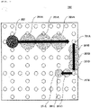
- Fig. 8 is a schematic diagram showing an example in which detection range setting is changed depending on a transport location of the transport device 102 in the present example.
- Example 1 The same components as those of Example 1 are denoted by the same reference numerals, and the description thereof will be omitted. The same applies to the following examples.
- the detection ranges 301A, 301B, and 301C are set to different ranges due to a difference in a position of a first transport path or a second transport path.
- a detection range at a detection point is narrowed, and the detection determination threshold 302C is set so as to have the detection range 301C or a pulse voltage for position detection is set, as described in Example 1, for example.
- the detection range at the detection point is widened, and the detection determination threshold 302A is set so as to have the detection range 301A or the pulse voltage for position detection is set, as described in Example 1, for example.
- the detection determination threshold 302B is set so as to have the detection range 301B or the pulse voltage for position detection is set, as described in Example 1, for example, such that in an intermediate portion connecting a high speed transport location and a retention location, the approach of the holder 202 can be detected quickly to some extent and can be detected with high sensitivity.
- the specimen transport system and the specimen transport method of Example 2 of the invention can also obtain substantially the same effects as those of the specimen transport system and the specimen transport method of Example 1 described above.
- the detection range does not necessarily have three types either, and may have two types or four or more types.
- Fig. 9 is a schematic top view of the transport device 102 showing detection range setting based on a moving distance in the present example.
- Fig. 10 is a flowchart showing a method of setting a detection range that varies depending on the moving distance in the present example.
- the detection ranges 301A, 301B, and 301C are set to be different depending on a difference in a continuous transport distance of the holder 202.
- a distance by which the holder 202 moves without temporary stop that is, a distance to a next standby destination position 701C is less than a predetermined distance D
- the detection range 301C which has a small detection range on a transport path to the standby destination position 701C, is set.
- the detection range 301B which is a medium size detection range on a transport path to the standby destination position 701B, is set.
- the detection range 301A which has a large detection range on a transport path to the standby destination position 701A, is set.
- the moving distances D and E shown in Fig. 9 can be set by the control computer 101 or set by a manufacturer of the specimen transport system 100.
- control computer 101 starts searching for a transport path to a predetermined target position of one holder 202 (step S601), and determines a next position from the standby destination positions 701A, 701B, and 701C (step S602) .
- control computer 101 determines whether a distance by which the holder 202 is transported to the target position without temporary stop is less than the predetermined distance D (step S603).
- step S604 the control computer 101 sets the detection range 301C as the detection range on the transport path (step S604).
- the holder 202 in which the detection range 301C on the transport path is set is transported to a predetermined standby destination position by the action of an electromagnetic force based on a drive signal for transport of the magnetic pole 207 from the control computer 101 (step S605) .
- the setting of the detection range on the transport path of the holder 202 is completed, and transport path setting and operation to the next standby destination position of the holder 202 is started (step S606) .
- step S603 when it is determined in step S603 that the transport distance is equal to or greater than the distance D, the control computer 101 determines whether the transport distance is equal to or greater than D and less than E (step S607).
- control computer 101 sets the detection range 301B as the detection range on the transport path (step S608).
- the holder 202 in which the detection range 301B on the transport path is set is transported to a predetermined standby destination position under the control of the control computer 101 (step S605), the detection range setting of the holder 202 is completed, and the transport path setting and operation to the next standby destination position of the holder 202 is started (step S606).
- step S607 when it is determined in step S607 that the transport distance of the holder 202 is not equal to or greater than the predetermined distance D and less than the predetermined distance E, the control computer 101 sets the detection range 301A as the detection range on the transport path (step S609).
- the holder 202 in which the detection range 301A on the transport path is set is transported to a predetermined standby destination position under the control of the control computer 101 (step S605), the setting of the detection range 301A of the holder 202 is completed, and the transport path setting and operation to the next standby destination position of the holder 202 is started (step S606).
- Fig. 10 the case where the detection range of the holder 202 is set in three types of large, medium, and small has been described, and in a case where the detection range is two types or four or more types, it is possible to set two types or four or more types of detection ranges in the specimen transport system 100 by determining the moving distance in the same manner.
- the specimen transport system and the specimen transport method of Example 3 of the invention can also obtain substantially the same effects as those of the specimen transport system and the specimen transport method of Example 1 described above.
- FIG. 11 to 14 are schematic top views of the transport device 102 showing detection range setting based on a transport density in the present example.
- FIG. 14 is a flowchart showing a method of setting a detection range that varies depending on the transport density in the present example.
- a detection range at a detection point is narrowed to reliably detect each of the holders 202, and the detection determination threshold 302C is set so as to have the detection range 301C, or a pulse voltage for position detection is set, as described in Example 1, for example.
- the detection determination threshold 302B is set so as to have the detection range 301B or the pulse voltage for position detection is set, as described in Example 1, for example.
- the detection determination threshold 302A is set so as to have the detection range 301A or the pulse voltage for position detection is set, as described in Example 1, for example.
- the control computer 101 starts searching for a transport path to a predetermined target position (standby destination position) of the holder 202 to be transported (step S801), and determines the next standby destination position (step S802).
- control computer 101 determines whether the predetermined number F or more of other holders 202 are present on an adjacent path of the transport path to the predetermined standby destination position of the holder 202 to be transported (step S803).
- step S804 the control computer 101 sets the detection range 301C as a detection range on the transport path of the holder 202 to be transported (step S804).
- the holder 202 in which the detection range 301C on the transport path is set is transported to the predetermined standby destination position by the action of an electromagnetic force based on a drive signal for transport of the magnetic pole 207 from the control computer 101 (step S805).
- the setting of the detection range on the transport path of the holder 202 is completed, and transport path setting and operation to the next standby destination position of the holder 202 is started (step S806).
- step S803 when it is determined in step S803 that the predetermined number F or more of other holders 202 are not present on the adjacent path of the transport path of the holder 202 to be transported, the control computer 101 then determines whether the predetermined value G or more and less than F of other holders 202 are present on the adjacent path of the transport path of the holder 202 to be transported (step S807).
- the detection range 301B is set as the detection range on the transport path of the holder 202 to be transported (step S808).
- the holder 202 in which the detection range 301B on the transport path is set is transported to a predetermined standby destination position (step S805), the detection range setting of the holder 202 is completed, and the transport path setting and operation to the next standby destination position of the holder 202 is started (step S806).
- step S807 when it is determined in step S807 that the number of other holders 202 is less than the predetermined value G, the control computer 101 sets the detection range 301A as the detection range of the holder 202 on the transport path (step S809).
- the holder 202 in which the detection range 301A on the transport path is set is transported to a predetermined standby destination position under the control of the control computer 101 (step S805), the setting of the detection range 301A of the holder 202 is completed, and the transport path setting and operation to the next standby destination position of the holder 202 is started (step S806).
- Fig. 14 the case where the detection range of the holder 202 is set in three types of large, medium, and small has been described, and in a case where the detection range is two types or four or more types, it is possible to set two types or four or more types of detection ranges in the specimen transport system 100 by determining the transport density of the holder 202 in the same manner.
- the specimen transport system and the specimen transport method of Example 4 of the invention can also obtain substantially the same effects as those of the specimen transport system and the specimen transport method of Example 1 described above.
- a part of a configuration of one example may be replaced with a configuration of another example, and the configuration of another embodiment may be added to the configuration of the one embodiment.
- a part of the configuration of each example may be added to, deleted from, or replaced with another configuration.
Landscapes
- Physics & Mathematics (AREA)
- Chemical & Material Sciences (AREA)
- Immunology (AREA)
- Biochemistry (AREA)
- Pathology (AREA)
- General Physics & Mathematics (AREA)
- Health & Medical Sciences (AREA)
- Life Sciences & Earth Sciences (AREA)
- Analytical Chemistry (AREA)
- General Health & Medical Sciences (AREA)
- Engineering & Computer Science (AREA)
- Combustion & Propulsion (AREA)
- Power Engineering (AREA)
- Electromagnetism (AREA)
- Automatic Analysis And Handling Materials Therefor (AREA)
- Non-Mechanical Conveyors (AREA)
- Linear Motors (AREA)
Abstract
Description
- The present invention relates to a specimen transport system and a specimen transport method in a specimen analysis device that analyzes a biological sample (hereinafter, referred to as a specimen) such as blood, plasma, serum, urine, and other body fluid, or a specimen pretreatment device that performs a pretreatment necessary for analysis.
- As an example of a laboratory sample delivery system, which is very flexible and gives high transport performance, and a corresponding operation method, PTL 1 discloses a laboratory sample delivery system including several container carriers, each of the container carriers including at least one magnetically active device, preferably at least one permanent magnet and being adapted to transport a sample container, a transport plane adapted to transport the container carriers, and several electromagnetic actuators disposed to be stationary below the transport plane and adapted to move the container carriers on the transport plane by applying a magnetic force to the container carriers.
- As an example of an inspection chamber sample distribution system in which a position on a transfer surface can be recognized, PTL 2 describes an inspection chamber sample distribution system including a transfer surface, a plurality of sample container carriers, a drive unit configured to move the sample container carriers on the transfer surface, and a control device configured to control the movement of the sample container carriers on the transfer surface by driving the drive unit such that the sample container carriers move along a corresponding transfer path. A plurality of optically recognizable geometric shapes are placed on the transfer surface, and each of the geometric shapes represents a dedicated field on the transfer surface.
-
- PTL 1:
JP-A-2017-77971 - PTL 2:
JP-A-2018-119962 - As a specimen treatment system for automatically analyzing a specimen which is a biological sample such as blood or urine, there are a specimen pretreatment system that performs input, centrifugation, dispensing, labeling, and the like of a specimen, and an automatic analysis system that analyzes a specimen treated by such a specimen pretreatment system.
- Specimen pretreatment systems and automatic analysis systems in the related art include a specimen transport line using a belt conveyor or the like in order to transport a specimen to a mechanism that performs a predetermined treatment and analysis. By mounting a plurality of such transport lines on the specimen transport system, the specimen is transported to a predetermined mechanism.
- PTL 1 discloses the laboratory sample delivery system that is very flexible and gives high transport performance.
- The technique described in PTL 2 is an example of the specimen transport method. PTL 2 discloses that a position sensor that detects a position of a permanent magnet installed in a holder on which a specimen vessel containing a specimen is mounted is provided, and by transporting the holder by exciting an electromagnetic actuator corresponding to a direction in which the specimen is to be transported according to position information detected by the position sensor, the specimen is transported to a desired position.
- In a specimen transport system using an electromagnetic actuator, as described in PTL 2, after the position information of the specimen is detected, the holder is transported by exciting the electromagnetic actuator existing in the direction in which the specimen is to be transported. By repeating this operation, the holder is transported to a predetermined position.
- Therefore, when the detection of the position information is delayed, a transport speed of the holder may be delayed.
- When performing transporting at a location where holders are densely disposed, collisions between the holders or erroneous detection of an adjacent holder may occur when accurate position information is not detected.
- In this regard, in the technique described in PTL 2, the position sensor is used for detecting the position information of the specimen, but a detection range of the position sensor is not considered. It has become clear by the study of the present inventors that it is necessary to improve a detection accuracy for the holder in implementing the specimen transport at higher speed and higher accuracy.
- Therefore, the invention provides a specimen transport system and a specimen transport method that support a transport method using an electromagnetic actuator and can transport a specimen at higher speed and more stably as compared to the related art.
- The invention includes a plurality of means for solving the above problems, and an example thereof is a specimen transport system that transports a specimen mounted on a specimen holder by sliding on a transport path by an interaction between a magnetic body and an electromagnet provided in the specimen holder. The specimen transport system includes a plurality of detection points each configured by the electromagnet and detecting a position of the magnetic body, and a plurality of transport paths provided above the plurality of detection points so as to cover the plurality of detection points. A detection range at a first detection point constituting a first transport path is different from a detection range at a second detection point constituting a second transport path different from the first transport path, among the plurality of transport paths.
- According to the invention, it is possible to provide a transport method using an electromagnetic actuator, and transport a specimen at higher speed and more stably as compared to the related art. Problems, configurations, and effects other than those described above will be further clarified with the following description of embodiments.
-
- [
Fig. 1] Fig. 1 is a schematic plan view showing a configuration of the entire specimen transport system according to Example 1 of the invention. - [
Fig. 2] Fig. 2 is a diagram showing a schematic configuration of a transport device configuring the specimen transport system according to Example 1. - [
Fig. 3] Fig. 3 is a diagram showing an example of a current change curve obtained by the transport device according to Example 1. - [
Fig. 4] Fig. 4 is a schematic diagram showing an example of a method of setting a detection range in the transport device according to Example 1. - [
Fig. 5] Fig. 5 is a schematic diagram showing an example of the method of setting a detection range in the transport device according to Example 1. - [
Fig. 6] Fig. 6 is a schematic diagram showing an example of the method of setting a detection range in the transport device according to Example 1. - [
Fig. 7] Fig. 7 is a diagram showing a state of a partial upper surface of the transport device according to Example 1. - [
Fig. 8] Fig. 8 is a diagram showing an example of an outline of detection range setting in a transport device configuring a specimen transport system according to Example 2 of the invention. - [
Fig. 9] Fig. 9 is a diagram showing an example of an outline of detection range setting in a transport device configuring a specimen transport system according to Example 3 of the invention. - [
Fig. 10] Fig. 10 is a flowchart illustrating a procedure for setting a detection range in the transport device according to Example 3. - [
Fig. 11] Fig. 11 is a diagram showing an example of an outline of detection range setting in a transport device configuring a specimen transport system according to Example 4 of the invention. - [
Fig. 12] Fig. 12 is a diagram showing an example of an outline of detection range setting in the transport device according to Example 4. - [
Fig. 13] Fig. 13 is a diagram showing an example of an outline of detection range setting in the transport device according to Example 4. - [
Fig. 14] Fig. 14 is a flowchart illustrating a procedure for setting a detection range in the transport device according to Example 4. - Hereinafter, examples of a specimen transport system and a specimen transport method of the invention will be described with reference to the drawings.
- A specimen transport system and a specimen transport method according to Example 1 of the invention will be described with reference to
Figs. 1 to 7 . - First, an overall configuration of the specimen transport system will be described with reference to
Fig. 1. Fig. 1 is a plan view showing a configuration of the entire specimen transport system according to Example 1 of the invention. - A
specimen transport system 100 according to Example 1 shown inFig. 1 is a system provided with an analysis device for automatically analyzing components of a specimen such as blood or urine. - Main components of the
specimen transport system 100 include a holder 202 (seeFig. 2 ) on which a specimen vessel 201 (seeFig. 2 ) containing a specimen such as blood or urine is mounted, or a plurality of (12 inFig. 1 )transport devices 102 that transport an empty holder, a plurality of (4 inFig. 1 )analysis devices 103, and acontrol computer 101 that integrally manages thespecimen transport system 100. - The
analysis device 103 is a unit for performing qualitative and quantitative analysis of components of a specimen transported by thetransport device 102. Analysis items in this unit are not particularly limited, and a configuration of a known automatic analysis device that analyzes biochemical items and immune items can be adopted. Further, when a plurality ofanalysis devices 103 are provided, theanalysis devices 103 may have the same specifications or different specifications, and the specifications are not particularly limited. - Each of the
transport devices 102 is a device that transports a specimen mounted on theholder 202 to a destination by sliding on a transport path by an interaction between a magnetic body 203 (seeFig. 2 ) provided on theholder 202 and magnetic poles 207 (seeFig. 2 ). The details will be described with reference toFig. 2 and the subsequent drawings. - The
control computer 101 controls an operation of the entire system including thetransport devices 102 and theanalysis devices 103, and is implemented by a computer including a display device such as a liquid crystal display, an input device, a storage device, a CPU, a memory, and the like. The control of the operation of each device by thecontrol computer 101 is executed based on various programs recorded in the storage device. - A control processing for the operation executed by the
control computer 101 may be integrated into one program, may be divided into a plurality of programs, or may be a combination thereof. A part or all of the programs may be implemented by dedicated hardware or may be modularized. - In the
control computer 101 of the present example,detection ranges holder 202 to theanalysis device 103. The details thereof will be described later. - In
Fig. 1 described above, the case where fouranalysis devices 103 are provided is described, and the number of the analysis devices is not particularly limited and may be one or more. Similarly, the number of thetransport devices 102 is not particularly limited and may be one or more. - The
specimen transport system 100 can be provided with various specimen pretreatment and post-treatment units that perform pretreatment and post-treatment on a specimen. A detailed configuration of the specimen pretreatment and post-treatment units is not particularly limited, and a configuration of a known pretreatment device can be adopted. - Next, a specific configuration of the
transport device 102 of the present example will be described with reference toFigs. 2 to 7 .Fig. 2 is a configuration diagram showing an outline of thetransport device 102.Fig. 3 is a diagram showing an example of a current change curve obtained in the transport device.Figs. 4 to 6 are schematic diagrams each showing an example of a method of setting a detection range in the transport device.Fig. 7 is a diagram showing a state of a partial upper surface of the transport device. - In
Fig. 2 , a plurality ofholders 202 on which thespecimen vessel 201 containing a specimen is installed are provided in thetransport device 102. Themagnetic body 203 is provided on a bottom surface portion of each of the plurality ofholders 202. - The
magnetic body 203 is formed of, for example, a permanent magnet such as neodymium or ferrite. Themagnetic body 203 can also be formed of other magnets and soft magnetic bodies, and can be formed of appropriate combinations thereof. - Although it is not necessary to provide the
magnetic body 203 on a lower surface of theholder 202, themagnetic body 203 is preferably provided on the lower surface from the viewpoint of efficiently applying a transport force of electromagnetic transport. - The
holder 202 including themagnetic body 203 moves in a sliding manner on atransport surface 204. In order to generate the transport force, a plurality ofmagnetic poles 207 each including acylindrical core 205 and a winding 206 wound around an outer periphery of thecore 205 are provided below thetransport surface 204. Themagnetic poles 207 constitute the plurality of detection points for detecting a position of themagnetic body 203. A plurality of transport paths are provided above themagnetic poles 207 so as to cover themagnetic poles 207. - In the
transport device 102 of the present example, the plurality ofmagnetic poles 207 provided therein are used to detect the position of themagnetic body 203 and are also used to transport themagnetic body 203, that is, to transport a specimen. - In the present example, specifications of the
magnetic poles 207 in thetransport device 102 are the same for all themagnetic poles 207, but the specifications are not necessarily the same. - The
magnetic pole 207 is connected to adrive unit 208 that applies a predetermined voltage to themagnetic pole 207 to cause a predetermined current to flow through the winding 206. Themagnetic pole 207 to which the voltage is applied by thedrive unit 208 acts as an electromagnet, and attracts themagnetic body 203 in theholder 202 on thetransport surface 204. After theholder 202 is attracted by themagnetic pole 207, the voltage applied to themagnetic pole 207 by thedrive unit 208 is stopped, and the voltage is applied by thedrive unit 208 to a differentmagnetic pole 207 adjacent to themagnetic pole 207 in the same manner as described above, so that themagnetic body 203 in theholder 202 is attracted to the adjacentmagnetic pole 207. - This procedure is repeated for all the
magnetic poles 207 constituting the transport paths to transport a specimen contained in thespecimen vessel 201, which is held by theholder 202 provided with themagnetic body 203, to a destination. - The current flowing through the winding 206 of the
magnetic pole 207 in transport is detected by acurrent detection unit 209. The current flowing through the winding 206 of themagnetic pole 207 detected by thecurrent detection unit 209 is sent to acalculation unit 210 to be digitized, and a currentchange amount curve 211 depending on a position of a specimen holder as shown inFig. 3 is acquired. By acquiring the currentchange amount curve 211 depending on a position of theholder 202, the position of theholder 202 can be detected. - The
calculation unit 210 specifies, based on a command from thecontrol computer 101, a position of a specimen based on the currentchange amount curve 211. The position detection processing may be executed by thecalculation unit 210 or thecontrol computer 101, and in the present example, various settings during the position detection are determined in thecontrol computer 101 and executed by thecalculation unit 210. - In addition, the
calculation unit 210 calculates the current flowing through each of thewindings 206 using various kinds of information such as position information, speed information, and weight information of theholder 202, and outputs a command signal to thedrive unit 208. Thedrive unit 208 applies a voltage to the corresponding winding 206 based on the command signal. - Next, an example of setting of a position detection range will be described with reference to
Figs. 4 to 6 . - In the present example,
thresholds magnetic body 203 by obtaining the currentchange amount curve 211 based on a current value detected by thecurrent detection unit 209 are set to different values for the transport paths, so that a range in which the position of theholder 202 is specified is different for the transport paths. - For example, as shown in
Fig. 4 , with respect to thedetection range 301A of themagnetic pole 207 disposed at a position a constituting a transport path A in thetransport device 102 shown inFig. 7 , thedetection determination threshold 302A is set to be smaller than thedetection determination thresholds detection determination threshold 302A in this way, an intersection distance A'-A" between the currentchange amount curve 211 and a straight line of thedetection determination threshold 302A is longer, and thedetection range 301A can be set wider than the detection ranges 301B and 301C described later. - In addition, as shown in
Fig. 5 , with respect to thedetection range 301B of themagnetic pole 207 disposed at a position b constituting a transport path B in thetransport device 102 shown inFig. 7 , thedetection determination threshold 302B is set to a value larger than thedetection determination threshold 302A and smaller than thedetection determination threshold 302C. Accordingly, an intersection distance B'-B" between the currentchange amount curve 211 and a straight line of thedetection determination threshold 302B is shorter than the intersection distance A'-A" between the currentchange amount curve 211 and the straight line of thedetection determination threshold 302A, and it is possible to set thedetection range 301B narrower than thedetection range 301A at themagnetic pole 207 belonging to the transport path A and wider than thedetection range 301C at themagnetic pole 207 belonging to a transport path C. - Further, as shown in
Fig. 6 , with respect to thedetection range 301C of themagnetic pole 207 disposed at a position c constituting the transport path C in thetransport device 102 shown inFig. 7 , thedetection determination threshold 302C is set to a value larger than thedetection determination thresholds change amount curve 211 and a straight line of thedetection determination threshold 302C is shorter than the intersection distance A'-A" and the intersection distance B'-B", and it is possible to set thedetection range 301C narrower than thedetection range 301A of themagnetic pole 207 belonging to the transport path A and thedetection range 301B of themagnetic pole 207 belonging to the transport path B. - With such settings, as shown in
Fig. 7 , in thetransport device 102 in which a plurality ofmagnetic poles 207 serving as position detection points are disposed in a lattice pattern below thetransport surface 204 ofFig. 7 , the plurality ofmagnetic poles 207 disposed are configured such that the position of theholder 202 can be specified individually in any of the detection ranges 301A, 301B, and 301C. - Any of the detection ranges 301A, 301B, and 301C preferably overlaps the others of detection ranges 301A, 301B, and 301C. Accordingly, the
holder 202 can be prevented from being lost as much as possible as theholder 202 is positioned in a narrow carry-out range, and it is possible to achieve more stable transport. - Each of the
detection range 301A at the position a, thedetection range 301B at the position b, and thedetection range 301C at the position c is not necessarily fixed all the times during the transport of a specimen, and even at the same position, thedetection range 301A, thedetection range 301B, and thedetection range 301C can be changed as needed according to a transport situation. - For example, the detection ranges 301A, 301B, and 301C can be changed according to the setting of the transport of the
holder 202, more specifically, according to a transport speed or a transport density of themagnetic poles 207. This enables stable speed control and avoidance of erroneous detection and collision of theholder 202. - When the ranges of the detection ranges 301A, 301B, and 301C are changed, the values of the
detection determination thresholds control computer 101. - In
Fig. 3 , the case where the detection range is set to three types of large, medium, and small has been described, and the detection range may be set to at least two types or more, and may be set to four types or more. - When two types of detection ranges are provided or four or more types of detection ranges are provided, setting of two types or four or more types of detection ranges can be implemented in the
specimen transport system 100 or thetransport device 102 by changing the value of the detection determination threshold in each of the detection ranges, as inFigs. 4 to 6 . - In the above embodiment, the embodiment in which the detection range setting is changed by changing the
detection determination thresholds magnetic pole 207 by thedrive unit 208. In this case, when it is desired to widen the detection range, the period of the applied pulse voltage is lengthened, and when it is desired to narrow the range, the period is shortened. - Such a change in the period of the pulse voltage applied to the
magnetic pole 207 can also be made according to a command signal for setting change from thecontrol computer 101, as in the case of setting thedetection determination thresholds - Next, effects of the present example will be described.
- The
specimen transport system 100 according to Example 1 of the invention described above includes a plurality of detection points each formed of themagnetic pole 207 and configured to detect a position of themagnetic body 203, and the plurality of transport paths A, B, and C provided above the plurality of detection points so as to cover the plurality of detection points. Among the plurality of transport paths A, B, and C, a detection range at a first detection point constituting a first transport path is different from a detection range at a second detection point constituting a second transport path different from the first transport path. - Thus, in a transport method using an electromagnetic actuator that slides the
holder 202 on a transport path by an interaction between themagnetic body 203 and themagnetic pole 207, for example, since the detection range is different depending on transport conditions, the position of theholder 202 can be obtained at higher speed and more stably as compared to the related art without providing a mechanism that detects theholder 202 on thetransport surface 204. - Therefore, it is possible to implement a high speed and stable specimen transport system and specimen transport method in which delays or erroneous detection in the position detection for the
holder 202 is prevented as compared to the related art. - In addition, since the detection ranges 301A, 301B, and 301C at the first detection point and the second detection point are different from each other based on the setting of the transport of a specimen, it is possible to set a detection range suitable for implementing the transport according to situations and plans of analysis of the specimen, and it is possible to implement further stable specimen transport at higher speed.
- Further, since the detection ranges 301A, 301B, and 301C are different from each other due to a difference in the transport density or a difference in the transport speed of the
holder 202, it is possible to prevent transport trouble such as contact between theholders 202 as compared to the related art, and thus it is possible to implement further stable specimen transport. - The
analysis device 103 that analyzes a specimen and thecontrol computer 101 that controls the detection points and an operation of theanalysis device 103 are further provided. Thecontrol computer 101 determines the detection ranges 301A, 301B, and 301C of the plurality of detection points for each setting of transport of theholder 202 to theanalysis device 103, so that even during the analysis of a specimen, it is possible to set a detection range suitable for implementing the transport according to situations and plans of analysis of the specimen, and thus it is possible to implement further stable specimen transport. - Further, since the
current detection unit 209 that detects a value of a current flowing through themagnetic pole 207 of each of the plurality of detection points is further provided, and thethresholds magnetic body 203 based on the current value detected by thecurrent detection unit 209 are different between the first detection point and the second detection point, it is possible to change the detection range without changing the setting of a pulse voltage for driving or a pulse voltage for position detection, and thus it is possible to implement further stable specimen transport. - Since the
drive unit 208 that applies a voltage to themagnetic pole 207 is further provided, and a period of a pulse voltage applied to themagnetic pole 207 by thedrive unit 208 is different between the first detection point and the second detection point, it is possible to change the detection range without changing the setting of the pulse voltage for driving, and thus it is possible to implement further stable specimen transport. - Further, the
control computer 101 changes the detection range at the first detection point and the detection range at the second detection point according to a transport situation, thereby obtaining an effect that it is possible to flexibly cope with a case where it is necessary to change the transport situation according to progress situations of analysis such as the input of an emergency specimen and analysis concentration of thespecific analysis device 103 or situations necessary for analysis results. - A specimen transport system and a specimen transport method according to Example 2 of the invention will be described with reference to
Fig. 8. Fig. 8 is a schematic diagram showing an example in which detection range setting is changed depending on a transport location of thetransport device 102 in the present example. - The same components as those of Example 1 are denoted by the same reference numerals, and the description thereof will be omitted. The same applies to the following examples.
- In the specimen transport system and the specimen transport method of the present example, the detection ranges 301A, 301B, and 301C are set to different ranges due to a difference in a position of a first transport path or a second transport path.
- More specifically, as shown in
Fig. 8 , in a place where retention of theholder 202 is likely to occur or a place where retention is expected, such as an inlet and outlet location, a specimen input location, or a specimen standby location of theanalysis device 103 in thespecimen transport system 100, a detection range at a detection point is narrowed, and thedetection determination threshold 302C is set so as to have thedetection range 301C or a pulse voltage for position detection is set, as described in Example 1, for example. - By narrowing the detection range in this way, a detection sensitivity at each detection point is increased, and it is possible to detect a minute position change of the
holder 202. Therefore, it is possible to implement transport in which trouble such as contact between theholders 202 is more reliably prevented, and it is possible to implement further stable specimen transport. - On the other hand, in a place where the
holder 202 is assumed to move at a high speed, such as an emergency specimen transport path, since there is a high demand for early detection of theholder 202 moving at a high speed, the detection range at the detection point is widened, and thedetection determination threshold 302A is set so as to have thedetection range 301A or the pulse voltage for position detection is set, as described in Example 1, for example. - By widening the detection range in this way, it is possible to quickly detect the approach of the
holder 202 to the detection point, and it is possible to quickly switch a voltage application to themagnetic pole 207 for transporting theholder 202. Thus, it is possible to more reliably achieve a high transport speed. - The
detection determination threshold 302B is set so as to have thedetection range 301B or the pulse voltage for position detection is set, as described in Example 1, for example, such that in an intermediate portion connecting a high speed transport location and a retention location, the approach of theholder 202 can be detected quickly to some extent and can be detected with high sensitivity. - Other configurations and operations are substantially the same as those of the specimen transport system and the specimen transport method of Example 1 described above, and detailed description thereof will be omitted.
- The specimen transport system and the specimen transport method of Example 2 of the invention can also obtain substantially the same effects as those of the specimen transport system and the specimen transport method of Example 1 described above.
- When the detection ranges 301A, 301B, and 301C are different due to a difference in the position of the first transport path or the second transport path, it is possible to implement specimen transport at higher speed and more stably.
- In the present example, the detection range does not necessarily have three types either, and may have two types or four or more types.
- A specimen transport system and a specimen transport method according to Example 3 of the invention will be described with reference to
Figs. 9 and10 .Fig. 9 is a schematic top view of thetransport device 102 showing detection range setting based on a moving distance in the present example.Fig. 10 is a flowchart showing a method of setting a detection range that varies depending on the moving distance in the present example. - In the specimen transport system and the specimen transport method of the present example, the detection ranges 301A, 301B, and 301C are set to be different depending on a difference in a continuous transport distance of the
holder 202. - For example, in
Fig. 9 , when a distance by which theholder 202 moves without temporary stop, that is, a distance to a nextstandby destination position 701C is less than a predetermined distance D, it is not necessary to perform transport at a high speed, and thus thedetection range 301C, which has a small detection range on a transport path to thestandby destination position 701C, is set. - In addition, when a distance of the
holder 202 to a predeterminedstandby destination position 701B is equal to or greater than D and is less than a predetermined value E greater than D, thedetection range 301B, which is a medium size detection range on a transport path to thestandby destination position 701B, is set. - Further, in a case other than the above conditions, that is, in a case where a distance of the
holder 202 to astandby destination position 701A is equal to or greater than E, since there are many cases where high speed transport is required, thedetection range 301A, which has a large detection range on a transport path to thestandby destination position 701A, is set. - It is desirable that the moving distances D and E shown in
Fig. 9 can be set by thecontrol computer 101 or set by a manufacturer of thespecimen transport system 100. - The flow of the detection range as described above will be described below with reference to
Fig. 10 . - First, the
control computer 101 starts searching for a transport path to a predetermined target position of one holder 202 (step S601), and determines a next position from the standby destination positions 701A, 701B, and 701C (step S602) . - Next, the
control computer 101 determines whether a distance by which theholder 202 is transported to the target position without temporary stop is less than the predetermined distance D (step S603). - When it is determined that the transport distance is less than D, the processing proceeds to step S604, and the
control computer 101 sets thedetection range 301C as the detection range on the transport path (step S604). - The
holder 202 in which thedetection range 301C on the transport path is set is transported to a predetermined standby destination position by the action of an electromagnetic force based on a drive signal for transport of themagnetic pole 207 from the control computer 101 (step S605) . When theholder 202 is transported to the predetermined standby destination position, the setting of the detection range on the transport path of theholder 202 is completed, and transport path setting and operation to the next standby destination position of theholder 202 is started (step S606) . - On the other hand, when it is determined in step S603 that the transport distance is equal to or greater than the distance D, the
control computer 101 determines whether the transport distance is equal to or greater than D and less than E (step S607). - When it is determined that the transport distance is equal to or greater than D and less than E, the
control computer 101 sets thedetection range 301B as the detection range on the transport path (step S608). - The
holder 202 in which thedetection range 301B on the transport path is set is transported to a predetermined standby destination position under the control of the control computer 101 (step S605), the detection range setting of theholder 202 is completed, and the transport path setting and operation to the next standby destination position of theholder 202 is started (step S606). - On the other hand, when it is determined in step S607 that the transport distance of the
holder 202 is not equal to or greater than the predetermined distance D and less than the predetermined distance E, thecontrol computer 101 sets thedetection range 301A as the detection range on the transport path (step S609). - The
holder 202 in which thedetection range 301A on the transport path is set is transported to a predetermined standby destination position under the control of the control computer 101 (step S605), the setting of thedetection range 301A of theholder 202 is completed, and the transport path setting and operation to the next standby destination position of theholder 202 is started (step S606). - In
Fig. 10 , the case where the detection range of theholder 202 is set in three types of large, medium, and small has been described, and in a case where the detection range is two types or four or more types, it is possible to set two types or four or more types of detection ranges in thespecimen transport system 100 by determining the moving distance in the same manner. - Other configurations and operations are substantially the same as those of the specimen transport system and the specimen transport method of Example 1 described above, and detailed description thereof will be omitted.
- The specimen transport system and the specimen transport method of Example 3 of the invention can also obtain substantially the same effects as those of the specimen transport system and the specimen transport method of Example 1 described above.
- Even when the detection ranges 301A, 301B, and 301C are different due to the difference in the continuous transport distance of the
holder 202, it is possible to implement specimen transport at higher speed and more stably. - A specimen transport system and a specimen transport method according to Example 4 of the invention will be described with reference to
Figs. 11 to 14 .Figs. 11 to 13 are schematic top views of thetransport device 102 showing detection range setting based on a transport density in the present example.FIG. 14 is a flowchart showing a method of setting a detection range that varies depending on the transport density in the present example. - In the specimen transport system and the specimen transport method of the present example, an embodiment in which the detection range is set according to the transport density of the
holder 202 will be described. - As shown in
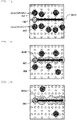
Fig. 11 , when a predetermined number F or more of theholders 202 are present on a transport path adjacent to anotherholder 202 to be transported, a detection range at a detection point is narrowed to reliably detect each of theholders 202, and thedetection determination threshold 302C is set so as to have thedetection range 301C, or a pulse voltage for position detection is set, as described in Example 1, for example. - In addition, as shown in
Fig. 12 , when a predetermined number G (less than F) or more and less than F ofother holders 202 are present on the adjacent transport path, thedetection determination threshold 302B is set so as to have thedetection range 301B or the pulse voltage for position detection is set, as described in Example 1, for example. - Further, as shown in
Fig. 13 , in a case of conditions other than the two conditions described above, high speed transport is possible since there are fewother holders 202 around, and therefore, the detection range at the detection point is widened, and thedetection determination threshold 302A is set so as to have thedetection range 301A or the pulse voltage for position detection is set, as described in Example 1, for example. - The flow of the detection range as described above will be described below with reference to
Fig. 14 . - As shown in
Fig. 14 , first, thecontrol computer 101 starts searching for a transport path to a predetermined target position (standby destination position) of theholder 202 to be transported (step S801), and determines the next standby destination position (step S802). - Next, the
control computer 101 determines whether the predetermined number F or more ofother holders 202 are present on an adjacent path of the transport path to the predetermined standby destination position of theholder 202 to be transported (step S803). - When it is determined that the number of
other holders 202 is F or more, the processing proceeds to step S804, and thecontrol computer 101 sets thedetection range 301C as a detection range on the transport path of theholder 202 to be transported (step S804). - The
holder 202 in which thedetection range 301C on the transport path is set is transported to the predetermined standby destination position by the action of an electromagnetic force based on a drive signal for transport of themagnetic pole 207 from the control computer 101 (step S805). When theholder 202 is transported to the predetermined standby destination position, the setting of the detection range on the transport path of theholder 202 is completed, and transport path setting and operation to the next standby destination position of theholder 202 is started (step S806). - On the other hand, when it is determined in step S803 that the predetermined number F or more of
other holders 202 are not present on the adjacent path of the transport path of theholder 202 to be transported, thecontrol computer 101 then determines whether the predetermined value G or more and less than F ofother holders 202 are present on the adjacent path of the transport path of theholder 202 to be transported (step S807). - When it is determined that the number of
other holders 202 is G or more and less than F, thedetection range 301B is set as the detection range on the transport path of theholder 202 to be transported (step S808). - The
holder 202 in which thedetection range 301B on the transport path is set is transported to a predetermined standby destination position (step S805), the detection range setting of theholder 202 is completed, and the transport path setting and operation to the next standby destination position of theholder 202 is started (step S806). - On the other hand, when it is determined in step S807 that the number of
other holders 202 is less than the predetermined value G, thecontrol computer 101 sets thedetection range 301A as the detection range of theholder 202 on the transport path (step S809). - The
holder 202 in which thedetection range 301A on the transport path is set is transported to a predetermined standby destination position under the control of the control computer 101 (step S805), the setting of thedetection range 301A of theholder 202 is completed, and the transport path setting and operation to the next standby destination position of theholder 202 is started (step S806). - In
Fig. 14 , the case where the detection range of theholder 202 is set in three types of large, medium, and small has been described, and in a case where the detection range is two types or four or more types, it is possible to set two types or four or more types of detection ranges in thespecimen transport system 100 by determining the transport density of theholder 202 in the same manner. - Other configurations and operations are substantially the same as those of the specimen transport system and the specimen transport method of Example 1 described above, and detailed description thereof will be omitted.
- The specimen transport system and the specimen transport method of Example 4 of the invention can also obtain substantially the same effects as those of the specimen transport system and the specimen transport method of Example 1 described above.
- The invention is not limited to the above examples, and includes various modifications. The above examples have been described in detail for easy understanding of the invention, and the invention is not necessarily limited to those including all the configurations described above.
- A part of a configuration of one example may be replaced with a configuration of another example, and the configuration of another embodiment may be added to the configuration of the one embodiment. A part of the configuration of each example may be added to, deleted from, or replaced with another configuration.
-
- 100:
- specimen transport system
- 101:
- control computer
- 102:
- transport device
- 103:
- analysis device
- 201:
- specimen vessel
- 202:
- holder
- 203:
- magnetic body
- 204:
- transport surface
- 205:
- core
- 206:
- winding
- 207:
- magnetic pole (electromagnet, each detection point)
- 208:
- drive unit
- 209:
- current detection unit
- 210:
- calculation unit
- 211:
- current change amount curve
- 301A, 301B, 301C:
- detection range
- 302A, 302B, 302C:
- detection determination threshold
- 701A, 701B, 701C:
- standby destination position
Claims (11)
- A specimen transport system that transports a specimen mounted on a specimen holder by sliding on a transport path by an interaction between a magnetic body and an electromagnet provided in the specimen holder, comprising:a plurality of detection points each configured by the electromagnet and detecting a position of the magnetic body; anda plurality of transport paths provided above the plurality of detection points so as to cover the plurality of detection points, whereina detection range at a first detection point constituting a first transport path is different from a detection range at a second detection point constituting a second transport path different from the first transport path, among the plurality of transport paths.
- The specimen transport system according to claim 1, wherein
the detection ranges of the first detection point and the second detection point are different based on the specimen transport setting. - The specimen transport system according to claim 2, wherein
the detection range varies depending on a transport density of the specimen holder. - The specimen transport system according to claim 2, wherein
the detection range varies depending on a position of the first transport path or the second transport path. - The specimen transport system according to claim 2, wherein
the detection range varies depending on a continuous transport distance of the specimen holder. - The specimen transport system according to claim 2, wherein
the detection range varies depending on a transport speed of the specimen holder. - The specimen transport system according to claim 1, further comprising:an analysis device configured to analyze the specimen; anda control computer configured to control the detection point, and the operation of the analysis device, whereinthe control computer determines detection ranges of the plurality of detection points for each setting of transport of the specimen holder to the analysis device.
- The specimen transport system according to claim 7, wherein
the control computer changes the detection range of the first detection point and the detection range of the second detection point in accordance with a transport situation. - The specimen transport system according to claim 1, further comprising:a current detection unit configured to detect a current value flowing through the electromagnet of each of the plurality of detection points, whereina threshold for calculating the position of the magnetic body based on the current value detected by the current detection unit is different between the first detection point and the second detection point.
- The specimen transport system according to claim 1, further comprising:a drive unit configured to apply a voltage to the electromagnet, whereina period of a pulse voltage applied to the electromagnet by the drive unit is different between the first detection point and the second detection point.
- A specimen transport method for transporting a specimen mounted on a specimen holder having a magnetic body, comprising:providing a plurality of detection points each configured by an electromagnet and detecting a position of the magnetic body, and a plurality of transport paths provided above the plurality of detection points so as to cover the plurality of detection points;setting a detection range at a first detection point constituting a first transport path to be different from a detection range at a second detection point constituting a second transport path different from the first transport path, among the plurality of transport paths; andtransporting the specimen by sliding the specimen holder on the transport path by an interaction between the magnetic body and the electromagnet.
Applications Claiming Priority (2)
| Application Number | Priority Date | Filing Date | Title |
|---|---|---|---|
| JP2020018352 | 2020-02-05 | ||
| PCT/JP2021/000410 WO2021157280A1 (en) | 2020-02-05 | 2021-01-07 | Specimen transport system and specimen transport method |
Publications (3)
| Publication Number | Publication Date |
|---|---|
| EP4101794A1 true EP4101794A1 (en) | 2022-12-14 |
| EP4101794A4 EP4101794A4 (en) | 2024-03-27 |
| EP4101794B1 EP4101794B1 (en) | 2026-06-03 |
Family
ID=77200501
Family Applications (1)
| Application Number | Title | Priority Date | Filing Date |
|---|---|---|---|
| EP21750712.8A Active EP4101794B1 (en) | 2020-02-05 | 2021-01-07 | Specimen transport system and specimen transport method |
Country Status (5)
| Country | Link |
|---|---|
| US (1) | US12480964B2 (en) |
| EP (1) | EP4101794B1 (en) |
| JP (1) | JP7459145B2 (en) |
| CN (1) | CN115053136B (en) |
| WO (1) | WO2021157280A1 (en) |
Families Citing this family (1)
| Publication number | Priority date | Publication date | Assignee | Title |
|---|---|---|---|---|
| CN119487397A (en) * | 2022-08-24 | 2025-02-18 | 美国西门子医学诊断股份有限公司 | State estimation using sparse Hall sensor based sensing |
Family Cites Families (12)
| Publication number | Priority date | Publication date | Assignee | Title |
|---|---|---|---|---|
| JPH05153704A (en) * | 1991-11-26 | 1993-06-18 | Hitachi Ltd | Method and apparatus for controlling planar magnetic repellent/attractive levitation control |
| JP2004117052A (en) * | 2002-09-24 | 2004-04-15 | Polymatech Co Ltd | Film sensor, electric actuator, and input device |
| EP2034324A3 (en) * | 2007-07-20 | 2010-06-16 | Koninklijke Philips Electronics N.V. | Sensor cartridge |
| EP2589967A1 (en) * | 2011-11-04 | 2013-05-08 | Roche Diagnostics GmbH | Laboratory sample distribution system and corresponding method of operation |
| EP2957914B1 (en) * | 2014-06-17 | 2018-01-03 | Roche Diagnostics GmbH | Laboratory sample distribution system and laboratory automation system |
| CN105301264A (en) * | 2015-09-12 | 2016-02-03 | 丁鸿 | Full-automatic coagulation analyzer equipment and detection method |
| DE102015117378B3 (en) * | 2015-10-13 | 2016-12-15 | Deutsches Elektronen- Synchrotron DESY | System for providing a sample in a measuring device |
| EP3343232B1 (en) | 2016-12-29 | 2021-09-15 | Roche Diagnostics GmbH | Laboratory sample distribution system and laboratory automation system |
| EP3355064A1 (en) | 2017-01-25 | 2018-08-01 | Roche Diagnostics GmbH | Laboratory sample distribution system and laboratory automation system |
| EP3410123B1 (en) * | 2017-06-02 | 2023-09-20 | Roche Diagnostics GmbH | Method of operating a laboratory sample distribution system, laboratory sample distribution system and laboratory automation system |
| WO2019082750A1 (en) * | 2017-10-24 | 2019-05-02 | パナソニックIpマネジメント株式会社 | Planar motor system, control device, and movement method |
| WO2019225284A1 (en) * | 2018-05-25 | 2019-11-28 | パナソニックIpマネジメント株式会社 | Planar motor and control method |
-
2021
- 2021-01-07 EP EP21750712.8A patent/EP4101794B1/en active Active
- 2021-01-07 US US17/794,458 patent/US12480964B2/en active Active
- 2021-01-07 JP JP2021575670A patent/JP7459145B2/en active Active
- 2021-01-07 CN CN202180012550.3A patent/CN115053136B/en active Active
- 2021-01-07 WO PCT/JP2021/000410 patent/WO2021157280A1/en not_active Ceased
Also Published As
| Publication number | Publication date |
|---|---|
| EP4101794A4 (en) | 2024-03-27 |
| US20230070391A1 (en) | 2023-03-09 |
| CN115053136B (en) | 2025-11-14 |
| EP4101794B1 (en) | 2026-06-03 |
| CN115053136A (en) | 2022-09-13 |
| JP7459145B2 (en) | 2024-04-01 |
| JPWO2021157280A1 (en) | 2021-08-12 |
| WO2021157280A1 (en) | 2021-08-12 |
| US12480964B2 (en) | 2025-11-25 |
Similar Documents
| Publication | Publication Date | Title |
|---|---|---|
| EP3905515B1 (en) | Conveying device, sample analysis system and sample preprocessing device comprising same, and method for conveying sample to be conveyed | |
| EP3355065B1 (en) | Laboratory sample distribution system and laboratory automation system | |
| JP7107866B2 (en) | Conveying device and conveying method of conveyed object | |
| EP2995381A1 (en) | Set of sample container carriers for a laboratory sample distribution system, laboratory sample distribution system and laboratory automation system | |
| EP3904889A1 (en) | Conveying device, sample analysis system comprising same, and sample preprocessing device | |
| EP3937359A1 (en) | Conveying device, and sample analysis system and sample preprocessing device comprising same | |
| US12411149B2 (en) | Specimen transport device, specimen analysis system, specimen pretreatment system, and specimen transport method | |
| US12480964B2 (en) | Specimen transport system and specimen transport method | |
| EP4393855A1 (en) | Sample conveyance device and sample conveyance method | |
| US12230441B2 (en) | Transport device and transport method | |
| US12565389B2 (en) | Sample conveyance system and sample conveyance method | |
| EP4484965A1 (en) | Transportation device and transportation method | |
| EP4197947B1 (en) | Specimen transport device, specimen analysis system, and specimen pretreatment device | |
| EP4577838A2 (en) | State estimation using sparse hall sensor-based sensing | |
| EP4685091A1 (en) | Conveyance device and conveyance method | |
| JP2025161371A (en) | Specimen transport device, specimen analysis system, and specimen pretreatment device | |
| JP2025097685A (en) | Specimen conveying device, specimen analysis system, and specimen pretreatment device | |
| WO2026034007A1 (en) | Conveyance device, specimen conveyance system, and conveyance method for conveyed body | |
| WO2022234759A1 (en) | Specimen transport device, specimen analysis system, and specimen pretreatment system |
Legal Events
| Date | Code | Title | Description |
|---|---|---|---|
| STAA | Information on the status of an ep patent application or granted ep patent |
Free format text: STATUS: THE INTERNATIONAL PUBLICATION HAS BEEN MADE |
|
| PUAI | Public reference made under article 153(3) epc to a published international application that has entered the european phase |
Free format text: ORIGINAL CODE: 0009012 |
|
| STAA | Information on the status of an ep patent application or granted ep patent |
Free format text: STATUS: REQUEST FOR EXAMINATION WAS MADE |
|
| 17P | Request for examination filed |
Effective date: 20220905 |
|
| AK | Designated contracting states |
Kind code of ref document: A1 Designated state(s): AL AT BE BG CH CY CZ DE DK EE ES FI FR GB GR HR HU IE IS IT LI LT LU LV MC MK MT NL NO PL PT RO RS SE SI SK SM TR |
|
| DAV | Request for validation of the european patent (deleted) | ||
| DAX | Request for extension of the european patent (deleted) | ||
| A4 | Supplementary search report drawn up and despatched |
Effective date: 20240226 |
|
| RIC1 | Information provided on ipc code assigned before grant |
Ipc: G01N 35/04 20060101ALI20240220BHEP Ipc: H02K 41/03 20060101ALI20240220BHEP Ipc: B65G 54/02 20060101AFI20240220BHEP |
|
| STAA | Information on the status of an ep patent application or granted ep patent |
Free format text: STATUS: EXAMINATION IS IN PROGRESS |
|
| 17Q | First examination report despatched |
Effective date: 20250303 |
|
| GRAP | Despatch of communication of intention to grant a patent |
Free format text: ORIGINAL CODE: EPIDOSNIGR1 |
|
| STAA | Information on the status of an ep patent application or granted ep patent |
Free format text: STATUS: GRANT OF PATENT IS INTENDED |
|
| INTG | Intention to grant announced |
Effective date: 20260213 |
|
| GRAS | Grant fee paid |
Free format text: ORIGINAL CODE: EPIDOSNIGR3 |
|
| GRAA | (expected) grant |
Free format text: ORIGINAL CODE: 0009210 |
|
| STAA | Information on the status of an ep patent application or granted ep patent |
Free format text: STATUS: THE PATENT HAS BEEN GRANTED |
|
| AK | Designated contracting states |
Kind code of ref document: B1 Designated state(s): AL AT BE BG CH CY CZ DE DK EE ES FI FR GB GR HR HU IE IS IT LI LT LU LV MC MK MT NL NO PL PT RO RS SE SI SK SM TR |
|
| REG | Reference to a national code |
Ref country code: CH Ref legal event code: F10 Free format text: ST27 STATUS EVENT CODE: U-0-0-F10-F00 (AS PROVIDED BY THE NATIONAL OFFICE) Effective date: 20260603 Ref country code: GB Ref legal event code: FG4D |
|
| REG | Reference to a national code |
Ref country code: DE Ref legal event code: R096 Ref document number: 602021055279 Country of ref document: DE |
|
| REG | Reference to a national code |
Ref country code: IE Ref legal event code: FG4D |