EP4101757A1 - Vertical takeoff and landing aircraft - Google Patents
Vertical takeoff and landing aircraft Download PDFInfo
- Publication number
- EP4101757A1 EP4101757A1 EP21750259.0A EP21750259A EP4101757A1 EP 4101757 A1 EP4101757 A1 EP 4101757A1 EP 21750259 A EP21750259 A EP 21750259A EP 4101757 A1 EP4101757 A1 EP 4101757A1
- Authority
- EP
- European Patent Office
- Prior art keywords
- vertical takeoff
- cabin
- landing
- rotors
- landing aircraft
- Prior art date
- Legal status (The legal status is an assumption and is not a legal conclusion. Google has not performed a legal analysis and makes no representation as to the accuracy of the status listed.)
- Granted
Links
Images


Classifications
-
- B—PERFORMING OPERATIONS; TRANSPORTING
- B64—AIRCRAFT; AVIATION; COSMONAUTICS
- B64C—AEROPLANES; HELICOPTERS
- B64C1/00—Fuselages; Constructional features common to fuselages, wings, stabilising surfaces or the like
- B64C1/28—Parts of fuselage relatively movable to improve pilots view
-
- B—PERFORMING OPERATIONS; TRANSPORTING
- B64—AIRCRAFT; AVIATION; COSMONAUTICS
- B64C—AEROPLANES; HELICOPTERS
- B64C27/00—Rotorcraft; Rotors peculiar thereto
- B64C27/22—Compound rotorcraft, i.e. aircraft using in flight the features of both aeroplane and rotorcraft
- B64C27/28—Compound rotorcraft, i.e. aircraft using in flight the features of both aeroplane and rotorcraft with forward-propulsion propellers pivotable to act as lifting rotors
-
- B—PERFORMING OPERATIONS; TRANSPORTING
- B64—AIRCRAFT; AVIATION; COSMONAUTICS
- B64C—AEROPLANES; HELICOPTERS
- B64C11/00—Propellers, e.g. of ducted type; Features common to propellers and rotors for rotorcraft
- B64C11/001—Shrouded propellers
-
- B—PERFORMING OPERATIONS; TRANSPORTING
- B64—AIRCRAFT; AVIATION; COSMONAUTICS
- B64C—AEROPLANES; HELICOPTERS
- B64C27/00—Rotorcraft; Rotors peculiar thereto
- B64C27/04—Helicopters
- B64C27/08—Helicopters with two or more rotors
-
- B—PERFORMING OPERATIONS; TRANSPORTING
- B64—AIRCRAFT; AVIATION; COSMONAUTICS
- B64C—AEROPLANES; HELICOPTERS
- B64C27/00—Rotorcraft; Rotors peculiar thereto
- B64C27/20—Rotorcraft characterised by having shrouded rotors, e.g. flying platforms
-
- B—PERFORMING OPERATIONS; TRANSPORTING
- B64—AIRCRAFT; AVIATION; COSMONAUTICS
- B64C—AEROPLANES; HELICOPTERS
- B64C27/00—Rotorcraft; Rotors peculiar thereto
- B64C27/22—Compound rotorcraft, i.e. aircraft using in flight the features of both aeroplane and rotorcraft
- B64C27/26—Compound rotorcraft, i.e. aircraft using in flight the features of both aeroplane and rotorcraft characterised by provision of fixed wings
-
- B—PERFORMING OPERATIONS; TRANSPORTING
- B64—AIRCRAFT; AVIATION; COSMONAUTICS
- B64U—UNMANNED AERIAL VEHICLES [UAV]; EQUIPMENT THEREFOR
- B64U30/00—Means for producing lift; Empennages; Arrangements thereof
- B64U30/20—Rotors; Rotor supports
- B64U30/29—Constructional aspects of rotors or rotor supports; Arrangements thereof
- B64U30/296—Rotors with variable spatial positions relative to the UAV body
- B64U30/297—Tilting rotors
-
- B—PERFORMING OPERATIONS; TRANSPORTING
- B64—AIRCRAFT; AVIATION; COSMONAUTICS
- B64U—UNMANNED AERIAL VEHICLES [UAV]; EQUIPMENT THEREFOR
- B64U30/00—Means for producing lift; Empennages; Arrangements thereof
- B64U30/20—Rotors; Rotor supports
- B64U30/29—Constructional aspects of rotors or rotor supports; Arrangements thereof
- B64U30/299—Rotor guards
Definitions
- the present invention relates to a vertical takeoff and landing aircraft.
- Vertical takeoff and landing aircrafts come in a variety of forms.
- a system (1) of providing propulsion devices separately for vertical takeoff and landing and for horizontal flight a system (2) of changing the angle of a propulsion device (e.g., Patent Literature 1), and a system (3) of changing, like a tail-sitter, the tilt of a fuselage itself.
- Patent Literature 1 JP 2016 - 501 773 A
- the system (1) is disadvantageous in terms of weight and cost because propulsion devices are provided separately for vertical takeoff and landing and for horizontal flight.
- the system (2) is disadvantageous in terms of weight, cost and reliability because a mechanism and/or control to change the angle of the propulsion device is complex.
- the system (3) is not always good in terms of comfort of a crew who gets in the fuselage and carrying of cargo that is loaded in the fuselage because the attitude of the fuselage itself greatly changes.
- the present invention has been conceived in view of the above points, and objects thereof include providing a vertical takeoff and landing aircraft that is capable of both vertical takeoff and landing and high-speed horizontal flight while keeping a crew, cargo and/or the like horizontal, and can achieve weight reduction, low cost and improvement of reliability.
- the present invention stated in claim 1 is a vertical takeoff and landing aircraft capable of vertical takeoff and landing and horizontal flight, including:
- the present invention stated in claim 2 is the vertical takeoff and landing aircraft according to claim 1, wherein parts of the protectors function as the fixed wings.
- the present invention stated in claim 3 is the vertical takeoff and landing aircraft according to claim 1 or 2, wherein as the hinge, a damper hinge is used, the damper hinge providing a greater resistance against the rotation of the connector as an angular velocity of the connector with respect to the cabin is greater.
- the present invention stated in claim 4 is the vertical takeoff and landing aircraft according to any one of claims 1 to 3, wherein the vertical takeoff and landing aircraft is configured to obtain a lift during the vertical takeoff and landing by the rotation of the rotors and obtain the lift during the horizontal flight by the fixed wings.
- the present invention stated in claim 5 is the vertical takeoff and landing aircraft according to any one of claims 1 to 4, wherein the protectors are configured such that parts of each of the protectors being a lower side and an upper side during the horizontal flight function as the fixed wings.
- the present invention stated in claim 6 is the vertical takeoff and landing aircraft according to any one of claims 1 to 5, wherein the hinge is provided at a position higher than a center of gravity of the cabin.
- a vertical takeoff and landing aircraft is capable of both vertical takeoff and landing and high-speed horizontal flight while keeping a crew, cargo and/or the like horizontal, and can achieve weight reduction, low cost and improvement of reliability.
- the vertical takeoff and landing aircraft of this embodiment is capable of vertical takeoff and landing and horizontal flight.
- FIG. 1A is a plan view showing the configuration of the vertical takeoff and landing aircraft of this embodiment during vertical takeoff and landing.
- FIG. 1B is a side view thereof.
- a vertical takeoff and landing aircraft 1 mainly includes a fuselage 2, (sets of) rotors 3, protectors 4, connectors 5, and hinges 6.
- the cabin 2 is a housing in which a crew can get and/or cargo can be loaded.
- the cabin 2 as a whole is formed to have a streamlined external shape.
- FIG. 1A and FIG. 1B show the cabin 2 in which only one crew member gets
- the cabin 2 may be configured as a cabin for a plurality of crew members to get in or as an unmanned or manned cabin to load and transport cargo.
- the rotors 3 are arranged.
- the rotors 3 are provided at two places on the front side and two places on the rear side, four places in total, so as to face in the upward/downward direction.
- the rotors 3 are driven by motors 31 to rotate.
- the rotors 3 on the front side rotate in opposite directions to one another
- the rotors 3 on the rear side rotate in opposite directions to one another. That is, in FIG. 1A , for example, the left-front rotors 3A and the right-rear rotors 3D rotate clockwise, and the right-front rotors 3B and the left-rear rotors 3C rotate counterclockwise.
- the protectors 4 are provided, one that surrounds and protects the rotors 3 at two places on the front side, and the other that surrounds and protects the rotors 3 at two places on the rear side.
- parts of the protectors 4 function as fixed wings 4A to 4D, which will be described later.
- the abovementioned motors 31 are attached to fixing members 41 that are provided at the lower end parts of the protectors 4, so that the rotors 3 are fixed to the protectors 4.
- the protectors 4 are opened in their upper sides and lower sides, and during vertical takeoff and landing, by rotation of the rotors 3, air above the protectors 4 is drawn into the protectors 4 and ejected from the protectors 4 downward as downward airflow.
- two connectors 5 are arranged parallel to one another so as to extend in the front-rear direction.
- the protectors 4 are attached, so that the front protector 4 and the rear protector 4 are connected to one another by the connectors 5.
- the connectors 5 are attached to the left side and the right side of the cabin 2 via the hinges 6 such that the connectors 5 are rotatable with respect to the cabin 2.
- the connectors 5 are thus attached to the cabin 2 via the hinges 6. Hence, as will be described later, even when the connectors 5 tilt from the state of extending in the horizontal direction (front-rear direction) and rotate such that the rear sides of the connectors 5 go up, the cabin 2 does not tilt from the state of facing in the front/rear direction shown in FIG. 1B . This is shown in FIG. 3 and will be described later.
- damper hinges are used as the hinges 6.
- the damper hinges provide greater resistance against rotation of the connectors 5 as the angular velocity of the connectors 5 with respect to the cabin 2 is greater.
- the hinges 6 do not have the damper function, namely, if, unlike this embodiment, the hinges 6 are not damper hinges, when the connectors 5 rotate rapidly with respect to the cabin 2, the cabin 2 may swing back and forth, namely, perform a pendulum motion, during and after the rapid rotation of the connectors 5, whereas if, like this embodiment, damper hinges are used as the hinges 6, even when the connectors 5 rotate rapidly, the hinges 6 resist the swing of the cabin 2 and can accurately prevent or reduce the back-and-forth swing of the cabin 2.
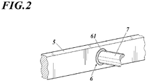
- the hinges 6 are each provided at an attachment part of an attachment 7 to the connector 5, the attachment 7 being attached to the cabin 2, which is not shown in FIG. 2 .
- a friction material 61 may be interposed as shown in FIG. 2 .
- oil may be interposed.
- dampers may be provided separately from the hinges 6.
- the connectors 5 are attached to the attachments 7 by the hinges 6 so as to rotate with no resistance, and the dampers function to provide resistance against rotation of the connectors 5.
- the hinges 6 are provided at positions higher than the center of gravity of the cabin 2. This configuration makes the cabin 2 kind of hang from the hinges 6.
- the hinges 6 are provided at positions lower than the center of gravity of the cabin 2, the cabin 2 is likely to rotate by falling forward or backward centering on the hinges 6 by its own weight, which decreases stability.
- the hinges 6 are provided at positions higher than the center of gravity of the cabin 2, the cabin 2 hangs from the hinges 6 as described above, and hence does not rotate with respect to the hinges 6, which maintains stability of the cabin 2.
- the hinges 6 are configured by damper hinges (or separate dampers from the hinges 6 are provided), the back-and-forth swing of the cabin 2 with respect to the hinges 6 is also prevented or reduced, which maintains stability of the cabin 2 more certainly.
- the hinges 6 are provided slightly forward of the center of gravity of the cabin 2. This is for the cabin 2 to keep the attitude to face in the substantially horizontal direction in balance with the crew and/or cargo in the cabin 2.
- the positions of the hinges 6 in the front-rear direction are determined as appropriate in accordance with the arrangement of the crew and/or cargo in the cabin 2.
- FIG. 3 is a side view showing the configuration of the vertical takeoff and landing aircraft of this embodiment during horizontal flight.
- the vertical takeoff and landing aircraft 1 of this embodiment obtains lift by rotation of the rotors 3 during vertical takeoff and landing.
- the connectors 5 rotate such that the rear sides of the connectors 5 go up while the cabin 2 keeps facing in the substantially horizontal direction, and as shown in FIG. 3 , tilt to the state of being nearly vertical.
- rotation of the rotors 3 contributes little to the lift of the vertical takeoff and landing aircraft 1, but generates airflow behind the vertical takeoff and landing aircraft 1. Accordingly, the vertical takeoff and landing aircraft 1 obtains forward thrust for horizontal flight by rotation of the rotors 3.
- parts of the protectors 4 function as the fixed wings 4A to 4D, and the vertical takeoff and landing aircraft 1 obtains the lift during horizontal flight by the fixed wings 4A to 4D.
- the vertical takeoff and landing aircraft 1 of this embodiment can perform vertical takeoff and landing and horizontal flight by the connectors 5 rotating with respect to the cabin 2 and accordingly the rotors 3 and the fixed wings 4A to 4D rotating around the cabin 2.
- the protectors 4 are formed at the both end parts of the connectors 5 so as to surround the rotors 3, and configured such that during horizontal flight ( FIG. 3 ), the lower parts 4A, 4C and the upper parts 4B, 4D of the protectors 4, which are during vertical takeoff and landing ( FIG. 1A and FIG. 1B ), the front parts 4A, 4C and the rear parts 4B, 4D of the protectors 4, function as the fixed wings 4A to 4D.
- the fixed wings 4A to 4D can each be formed, for example, to have a cross-section shape of the upper surface bulging more than the lower surface, which is a shape often used for wings of airplanes, they each may be formed, as shown in FIG. 4 , to have a cross-section shape of being perfectly symmetrical about the centerline.
- the rotors 3 (their rates of rotation or the like) of the vertical takeoff and landing aircraft 1 are controlled basically in the same manner as those of a quadcopter having the same number of (sets of) rotors as the number of (sets of) rotors 3 of the vertical takeoff and landing aircraft 1.
- a quadcopter when rotors tilt to the extent that they face in the substantial horizontal direction, the lift cannot be obtained from rotation of the rotors, and accordingly possibility of crashes increases. Hence, the rotors cannot be tilted greatly.
- the lift is obtained from the fixed wings 4A to 4D.
- the rotors 3 (connectors 5) can be tilted to the extent that they face in the substantially horizontal direction, and rotation of the rotors 3 can be used as the thrust, which enables high-speed flight.
- the connectors 5 are attached to the left side and the right side of the cabin 2, which is capable of carrying a crew and/or cargo, via the hinges 6 such that the connectors 5 are rotatable with respect to the cabin 2, and the rotors 3 are arranged in the protectors 4 that are attached to the both ends of the connectors 5 (front end and rear end of each of the connectors 5 during vertical takeoff and landing).
- the vertical takeoff and landing aircraft 1 is configured to perform vertical takeoff and landing by obtaining lift by rotation of the rotors 3 and perform horizontal flight by obtaining lift by the fixed wings 4A to 4D and thrust by rotation of the rotors 3, by the connectors 5 rotating with respect to the cabin 2.
- the vertical takeoff and landing aircraft 1 of this embodiment uses the rotors 3 as a vertical propulsion device during vertical takeoff and landing and as a forward propulsion device during horizontal flight.
- the vertical takeoff and landing aircraft 1 of this embodiment does not require any mechanism or control to change the angle of the rotors 3, which are of the propulsion devices, namely, to change the state of the rotors 3 from the state of facing upward during vertical takeoff and landing to the state of facing sideways during horizontal flight.
- the angle of the rotors 3 can be changed by only increasing the rate of rotation (lift) of the rotors 3 positioned on the rear side during vertical takeoff and landing to be higher than the rate of rotation (lift) of the rotors 3 positioned on the front side during vertical takeoff and landing.
- the cabin 2 does not tilt accordingly and keeps facing in the horizontal direction.
- the vertical takeoff and landing aircraft 1 of this embodiment can fly while keeping a crew who boards the aircraft 1, cargo that is loaded in the cabin 2 and/or the like horizontal, and hence is excellent in terms of comfort of the crew who boards the aircraft 1, stability of carrying of the cargo that is loaded into the cabin 2, and so forth.
- the vertical takeoff and landing aircraft 1 of this embodiment is capable of both vertical takeoff and landing and high-speed horizontal flight while keeping a crew, cargo and/or the like horizontal.
- parts of the protectors 4 function as the fixed wings 4A to 4D, but, instead of parts of the protectors 4 functioning as the fixed wings 4A to 4D, fixed wings may be provided separately from the protectors 4.
- the present invention is applicable to a vertical takeoff and landing aircraft.
Landscapes
- Engineering & Computer Science (AREA)
- Aviation & Aerospace Engineering (AREA)
- Mechanical Engineering (AREA)
- Chemical & Material Sciences (AREA)
- Combustion & Propulsion (AREA)
- Body Structure For Vehicles (AREA)
- Fluid-Damping Devices (AREA)
- Vehicle Step Arrangements And Article Storage (AREA)
Abstract
Description
- The present invention relates to a vertical takeoff and landing aircraft.
- Vertical takeoff and landing aircrafts come in a variety of forms. In order to achieve both vertical takeoff and landing and high-speed horizontal flight, there are, for example, a system (1) of providing propulsion devices separately for vertical takeoff and landing and for horizontal flight, a system (2) of changing the angle of a propulsion device (e.g., Patent Literature 1), and a system (3) of changing, like a tail-sitter, the tilt of a fuselage itself.
- Patent Literature 1:
JP 2016 501 773 A - However, the system (1) is disadvantageous in terms of weight and cost because propulsion devices are provided separately for vertical takeoff and landing and for horizontal flight. Further, the system (2) is disadvantageous in terms of weight, cost and reliability because a mechanism and/or control to change the angle of the propulsion device is complex. Still further, the system (3) is not always good in terms of comfort of a crew who gets in the fuselage and carrying of cargo that is loaded in the fuselage because the attitude of the fuselage itself greatly changes.
- The present invention has been conceived in view of the above points, and objects thereof include providing a vertical takeoff and landing aircraft that is capable of both vertical takeoff and landing and high-speed horizontal flight while keeping a crew, cargo and/or the like horizontal, and can achieve weight reduction, low cost and improvement of reliability.
- In order to solve the abovementioned problem(s), the present invention stated in claim 1 is a vertical takeoff and landing aircraft capable of vertical takeoff and landing and horizontal flight, including:
- a cabin capable of carrying a crew and/or a cargo;
- rotors positioned in front of and behind the cabin during the vertical takeoff and landing;
- protectors that surround the rotors;
- a connector that connects the protectors to one another; and
- a hinge that attaches the connector to the cabin such that the connector is rotatable with respect to the cabin,
- wherein the vertical takeoff and landing aircraft performs the vertical takeoff and landing and the horizontal flight by the connector rotating with respect to the cabin and accordingly the rotors and fixed wings rotating around the cabin.
- The present invention stated in
claim 2 is the vertical takeoff and landing aircraft according to claim 1, wherein parts of the protectors function as the fixed wings. - The present invention stated in
claim 3 is the vertical takeoff and landing aircraft according toclaim 1 or 2, wherein as the hinge, a damper hinge is used, the damper hinge providing a greater resistance against the rotation of the connector as an angular velocity of the connector with respect to the cabin is greater. - The present invention stated in
claim 4 is the vertical takeoff and landing aircraft according to any one of claims 1 to 3, wherein the vertical takeoff and landing aircraft is configured to obtain a lift during the vertical takeoff and landing by the rotation of the rotors and obtain the lift during the horizontal flight by the fixed wings. - The present invention stated in
claim 5 is the vertical takeoff and landing aircraft according to any one of claims 1 to 4, wherein the protectors are configured such that parts of each of the protectors being a lower side and an upper side during the horizontal flight function as the fixed wings. - The present invention stated in
claim 6 is the vertical takeoff and landing aircraft according to any one of claims 1 to 5, wherein the hinge is provided at a position higher than a center of gravity of the cabin. - According to the present invention, a vertical takeoff and landing aircraft is capable of both vertical takeoff and landing and high-speed horizontal flight while keeping a crew, cargo and/or the like horizontal, and can achieve weight reduction, low cost and improvement of reliability.
-
-
FIG. 1A is a plan view showing the configuration of a vertical takeoff and landing aircraft of an embodiment(s) during vertical takeoff and landing. -
FIG. 1B is a side view showing the configuration of the vertical takeoff and landing aircraft of the embodiment during vertical takeoff and landing. -
FIG. 2 shows a configuration example in which a hinge is configured by a damper hinge. -
FIG. 3 is a side view showing the configuration of the vertical takeoff and landing aircraft of the embodiment during horizontal flight. -
FIG. 4 is a cross-section view showing an example of a fixed wing formed to have a cross-section shape of being perfectly symmetrical about the centerline. - Hereinafter, embodiments of a vertical takeoff and landing aircraft according to the present invention will be described.
- The vertical takeoff and landing aircraft of this embodiment is capable of vertical takeoff and landing and horizontal flight.
- First, the configuration of the vertical takeoff and landing aircraft during vertical takeoff and landing will be described with reference to the drawings.
FIG. 1A is a plan view showing the configuration of the vertical takeoff and landing aircraft of this embodiment during vertical takeoff and landing.FIG. 1B is a side view thereof. - A vertical takeoff and landing aircraft 1 mainly includes a
fuselage 2, (sets of)rotors 3,protectors 4,connectors 5, andhinges 6. - The
cabin 2 is a housing in which a crew can get and/or cargo can be loaded. In this embodiment, thecabin 2 as a whole is formed to have a streamlined external shape. - Although
FIG. 1A and FIG. 1B show thecabin 2 in which only one crew member gets, thecabin 2 may be configured as a cabin for a plurality of crew members to get in or as an unmanned or manned cabin to load and transport cargo. - In front of and behind the
cabin 2, therotors 3 are arranged. In this embodiment, therotors 3 are provided at two places on the front side and two places on the rear side, four places in total, so as to face in the upward/downward direction. - The
rotors 3 are driven bymotors 31 to rotate. In this embodiment, in relation to the moment or the like that is applied to the fuselage, therotors 3 on the front side rotate in opposite directions to one another, and therotors 3 on the rear side rotate in opposite directions to one another. That is, inFIG. 1A , for example, the left-front rotors 3A and the right-rear rotors 3D rotate clockwise, and the right-front rotors 3B and the left-rear rotors 3C rotate counterclockwise. - The
protectors 4 are provided, one that surrounds and protects therotors 3 at two places on the front side, and the other that surrounds and protects therotors 3 at two places on the rear side. - In this embodiment, parts of the
protectors 4 function asfixed wings 4A to 4D, which will be described later. - In this embodiment, the
abovementioned motors 31 are attached to fixingmembers 41 that are provided at the lower end parts of theprotectors 4, so that therotors 3 are fixed to theprotectors 4. - The
protectors 4 are opened in their upper sides and lower sides, and during vertical takeoff and landing, by rotation of therotors 3, air above theprotectors 4 is drawn into theprotectors 4 and ejected from theprotectors 4 downward as downward airflow. - On the left side and the right side of the
cabin 2, twoconnectors 5 are arranged parallel to one another so as to extend in the front-rear direction. - To the front ends and the rear ends of the
connectors 5, theprotectors 4 are attached, so that thefront protector 4 and therear protector 4 are connected to one another by theconnectors 5. - The
connectors 5 are attached to the left side and the right side of thecabin 2 via thehinges 6 such that theconnectors 5 are rotatable with respect to thecabin 2. - In this embodiment, the
connectors 5 are thus attached to thecabin 2 via thehinges 6. Hence, as will be described later, even when theconnectors 5 tilt from the state of extending in the horizontal direction (front-rear direction) and rotate such that the rear sides of theconnectors 5 go up, thecabin 2 does not tilt from the state of facing in the front/rear direction shown inFIG. 1B . This is shown inFIG. 3 and will be described later. - In this embodiment, as the
hinges 6, damper hinges are used. The damper hinges provide greater resistance against rotation of theconnectors 5 as the angular velocity of theconnectors 5 with respect to thecabin 2 is greater. - That is, when the
connectors 5 rotate slowly with respect to thecabin 2, theconnectors 5 rotate with little resistance from the hinges 6 (damper hinges), whereas when theconnectors 5 rotate rapidly with respect to thecabin 2, theconnectors 5 rotate with resistance from the hinges 6 (damper hinges). - If the
hinges 6 do not have the damper function, namely, if, unlike this embodiment, thehinges 6 are not damper hinges, when theconnectors 5 rotate rapidly with respect to thecabin 2, thecabin 2 may swing back and forth, namely, perform a pendulum motion, during and after the rapid rotation of theconnectors 5, whereas if, like this embodiment, damper hinges are used as thehinges 6, even when theconnectors 5 rotate rapidly, thehinges 6 resist the swing of thecabin 2 and can accurately prevent or reduce the back-and-forth swing of thecabin 2. - In this embodiment, the hinges 6 (damper hinges) are each provided at an attachment part of an
attachment 7 to theconnector 5, theattachment 7 being attached to thecabin 2, which is not shown inFIG. 2 . Between theconnector 5 and theattachment 7, afriction material 61 may be interposed as shown inFIG. 2 . - Instead of or in addition to the
friction materials 61, oil may be interposed. - Although not shown, dampers may be provided separately from the
hinges 6. In this case, for example, theconnectors 5 are attached to theattachments 7 by thehinges 6 so as to rotate with no resistance, and the dampers function to provide resistance against rotation of theconnectors 5. - In this embodiment, the
hinges 6 are provided at positions higher than the center of gravity of thecabin 2. This configuration makes thecabin 2 kind of hang from thehinges 6. - If the
hinges 6 are provided at positions lower than the center of gravity of thecabin 2, thecabin 2 is likely to rotate by falling forward or backward centering on thehinges 6 by its own weight, which decreases stability. - As in this embodiment, if the
hinges 6 are provided at positions higher than the center of gravity of thecabin 2, thecabin 2 hangs from thehinges 6 as described above, and hence does not rotate with respect to thehinges 6, which maintains stability of thecabin 2. - In the above case, if the
hinges 6 are configured by damper hinges (or separate dampers from thehinges 6 are provided), the back-and-forth swing of thecabin 2 with respect to thehinges 6 is also prevented or reduced, which maintains stability of thecabin 2 more certainly. - The same applies to when the
connectors 5 rotate with respect to thecabin 2. That is, even when theconnectors 5 rotate with respect to thecabin 2, thecabin 2 keeps hanging from thehinges 6 and stably keeps facing (being oriented) in a substantially horizontal direction. - In this embodiment, the
hinges 6 are provided slightly forward of the center of gravity of thecabin 2. This is for thecabin 2 to keep the attitude to face in the substantially horizontal direction in balance with the crew and/or cargo in thecabin 2. The positions of thehinges 6 in the front-rear direction are determined as appropriate in accordance with the arrangement of the crew and/or cargo in thecabin 2. - Next, the configuration of the vertical takeoff and landing aircraft 1 during horizontal flight will be described, and also effects of the vertical takeoff and landing aircraft 1 of this embodiment, structures of the fixed
wings 4A to 4D, and so forth will be described. -
FIG. 3 is a side view showing the configuration of the vertical takeoff and landing aircraft of this embodiment during horizontal flight. - When the
rotors 3 are rotated in the state of vertical takeoff and landing as shown inFIG. 1A and FIG. 1B , the vertical takeoff and landing aircraft 1 ascends in a substantially vertical direction. - Thus, the vertical takeoff and landing aircraft 1 of this embodiment obtains lift by rotation of the
rotors 3 during vertical takeoff and landing. - Then, in the sky, by increasing the lift of the
rear rotors 3, for example, by increasing the rate of rotation of therear rotors 3 to be higher than that of thefront rotors 3, and optionally reducing the lift of thefront rotors 3 at the same time, theconnectors 5 rotate such that the rear sides of theconnectors 5 go up while thecabin 2 keeps facing in the substantially horizontal direction, and as shown inFIG. 3 , tilt to the state of being nearly vertical. - As a result, the
rotors 3 and theprotectors 4 at both ends of theconnectors 5 are positioned above and below thecabin 2. - In this state, rotation of the
rotors 3 contributes little to the lift of the vertical takeoff and landing aircraft 1, but generates airflow behind the vertical takeoff and landing aircraft 1. Accordingly, the vertical takeoff and landing aircraft 1 obtains forward thrust for horizontal flight by rotation of therotors 3. - In this embodiment, as described above, parts of the
protectors 4 function as the fixedwings 4A to 4D, and the vertical takeoff and landing aircraft 1 obtains the lift during horizontal flight by the fixedwings 4A to 4D. - Thus, the vertical takeoff and landing aircraft 1 of this embodiment can perform vertical takeoff and landing and horizontal flight by the
connectors 5 rotating with respect to thecabin 2 and accordingly therotors 3 and the fixedwings 4A to 4D rotating around thecabin 2. - In this embodiment, as described above, the
protectors 4 are formed at the both end parts of theconnectors 5 so as to surround therotors 3, and configured such that during horizontal flight (FIG. 3 ), thelower parts upper parts protectors 4, which are during vertical takeoff and landing (FIG. 1A and FIG. 1B ), thefront parts rear parts protectors 4, function as the fixedwings 4A to 4D. - Although the fixed
wings 4A to 4D can each be formed, for example, to have a cross-section shape of the upper surface bulging more than the lower surface, which is a shape often used for wings of airplanes, they each may be formed, as shown inFIG. 4 , to have a cross-section shape of being perfectly symmetrical about the centerline. - Even if the cross-section shape of each of the fixed
wings 4A to 4D is perfectly symmetrical, sufficient lift can be obtained as far as the angle of attack α is appropriate. - The rotors 3 (their rates of rotation or the like) of the vertical takeoff and landing aircraft 1 are controlled basically in the same manner as those of a quadcopter having the same number of (sets of) rotors as the number of (sets of)
rotors 3 of the vertical takeoff and landing aircraft 1. However, in the case of a quadcopter, when rotors tilt to the extent that they face in the substantial horizontal direction, the lift cannot be obtained from rotation of the rotors, and accordingly possibility of crashes increases. Hence, the rotors cannot be tilted greatly. - In this regard, in this embodiment, during horizontal flight, the lift is obtained from the fixed
wings 4A to 4D. Hence, as shown inFIG. 3 , the rotors 3 (connectors 5) can be tilted to the extent that they face in the substantially horizontal direction, and rotation of therotors 3 can be used as the thrust, which enables high-speed flight. - As described above, according to the vertical takeoff and landing aircraft 1 of this embodiment, the
connectors 5 are attached to the left side and the right side of thecabin 2, which is capable of carrying a crew and/or cargo, via thehinges 6 such that theconnectors 5 are rotatable with respect to thecabin 2, and therotors 3 are arranged in theprotectors 4 that are attached to the both ends of the connectors 5 (front end and rear end of each of theconnectors 5 during vertical takeoff and landing). - Further, parts of the
protectors 4 function as the fixedwings 4A to 4D. The vertical takeoff and landing aircraft 1 is configured to perform vertical takeoff and landing by obtaining lift by rotation of therotors 3 and perform horizontal flight by obtaining lift by the fixedwings 4A to 4D and thrust by rotation of therotors 3, by theconnectors 5 rotating with respect to thecabin 2. - Thus, the vertical takeoff and landing aircraft 1 of this embodiment uses the
rotors 3 as a vertical propulsion device during vertical takeoff and landing and as a forward propulsion device during horizontal flight. - This can curb increase in weight and cost as compared with a case where propulsion devices are provided separately for vertical takeoff and landing and for horizontal flight.
- Further, the vertical takeoff and landing aircraft 1 of this embodiment does not require any mechanism or control to change the angle of the
rotors 3, which are of the propulsion devices, namely, to change the state of therotors 3 from the state of facing upward during vertical takeoff and landing to the state of facing sideways during horizontal flight. The angle of therotors 3 can be changed by only increasing the rate of rotation (lift) of therotors 3 positioned on the rear side during vertical takeoff and landing to be higher than the rate of rotation (lift) of therotors 3 positioned on the front side during vertical takeoff and landing. - No requirement of the mechanism or control to change the angle of the
rotors 3 can curb increase in weight and cost. No requirement of such a mechanism means that there is no mechanism that could be a cause of trouble. Hence, the vertical takeoff and landing aircraft 1 of this embodiment is also superior in terms of reliability. - Further, even when the
connectors 5 tilt from the state of extending in the horizontal direction (front-rear direction) and rotate such that the rear sides of theconnectors 5 go up, namely, even when therotors 3 and the fixedwings 4A to 4D change their state from the state of being positioned in front of and behind thecabin 2 to the state of being positioned above and below thecabin 2, thecabin 2 does not tilt accordingly and keeps facing in the horizontal direction. - Hence, as compared with a case, such as a case of a general tail-sitter, where the attitude changes to tilt according to the tilt of the
rotors 3 or the like, the vertical takeoff and landing aircraft 1 of this embodiment can fly while keeping a crew who boards the aircraft 1, cargo that is loaded in thecabin 2 and/or the like horizontal, and hence is excellent in terms of comfort of the crew who boards the aircraft 1, stability of carrying of the cargo that is loaded into thecabin 2, and so forth. - Thus, the vertical takeoff and landing aircraft 1 of this embodiment is capable of both vertical takeoff and landing and high-speed horizontal flight while keeping a crew, cargo and/or the like horizontal.
- Also, it can achieve weight reduction, low cost and improvement of reliability.
- Although one or more embodiments of the present invention have been described above, it goes without saying that the present invention is not limited to the above embodiments or the like but can be appropriately modified without departing from the scope of the present invention.
- For example, in the above embodiments, parts of the
protectors 4 function as the fixedwings 4A to 4D, but, instead of parts of theprotectors 4 functioning as the fixedwings 4A to 4D, fixed wings may be provided separately from theprotectors 4. - The present invention is applicable to a vertical takeoff and landing aircraft.
-
- 1
- Vertical Takeoff and Landing Aircraft
- 2
- Cabin
- 3
- Rotor
- 4
- Protector
- 4A to 4D
- Fixed Wing
- 5
- Connector
- 6
- Hinge
Claims (6)
- A vertical takeoff and landing aircraft capable of vertical takeoff and landing and horizontal flight, comprising:- a cabin capable of carrying a crew and/or a cargo;- rotors positioned in front of and behind the cabin during the vertical takeoff and landing;- protectors that surround the rotors;- a connector that connects the protectors to one another; and- a hinge that attaches the connector to the cabin such that the connector is rotatable with respect to the cabin,
wherein the vertical takeoff and landing aircraft is configured to perform the vertical takeoff and landing and the horizontal flight by the connector rotating with respect to the cabin and accordingly the rotors and fixed wings rotating around the cabin. - The vertical takeoff and landing aircraft according to claim 1,
wherein parts of the protectors function as the fixed wings. - The vertical takeoff and landing aircraft according to claim 1 or 2,
wherein as the hinge, a damper hinge is used, the damper hinge providing a greater resistance against the rotation of the connector as an angular velocity of the connector with respect to the cabin is greater. - The vertical takeoff and landing aircraft according to any one of claims 1 to 3, wherein the vertical takeoff and landing aircraft is configured to obtain a lift during the vertical takeoff and landing by the rotation of the rotors and obtain the lift during the horizontal flight by the fixed wings.
- The vertical takeoff and landing aircraft according to any one of claims 1 to 4, wherein the protectors are configured such that parts of each of the protectors being a lower side and an upper side during the horizontal flight function as the fixed wings.
- The vertical takeoff and landing aircraft according to any one of claims 1 to 5, wherein the hinge is provided at a position higher than a center of gravity of the cabin.
Applications Claiming Priority (2)
| Application Number | Priority Date | Filing Date | Title |
|---|---|---|---|
| JP2020016677A JP7541830B2 (en) | 2020-02-04 | 2020-02-04 | Vertical take-off and landing aircraft |
| PCT/JP2021/001700 WO2021157343A1 (en) | 2020-02-04 | 2021-01-19 | Vertical takeoff and landing aircraft |
Publications (3)
| Publication Number | Publication Date |
|---|---|
| EP4101757A1 true EP4101757A1 (en) | 2022-12-14 |
| EP4101757A4 EP4101757A4 (en) | 2024-01-17 |
| EP4101757B1 EP4101757B1 (en) | 2026-04-29 |
Family
ID=77199266
Family Applications (1)
| Application Number | Title | Priority Date | Filing Date |
|---|---|---|---|
| EP21750259.0A Active EP4101757B1 (en) | 2020-02-04 | 2021-01-19 | Vertical takeoff and landing aircraft |
Country Status (5)
| Country | Link |
|---|---|
| US (1) | US12195174B2 (en) |
| EP (1) | EP4101757B1 (en) |
| JP (1) | JP7541830B2 (en) |
| CN (1) | CN115003599A (en) |
| WO (1) | WO2021157343A1 (en) |
Cited By (1)
| Publication number | Priority date | Publication date | Assignee | Title |
|---|---|---|---|---|
| PL444951A1 (en) * | 2023-05-22 | 2024-11-25 | Sieć Badawcza Łukasiewicz - Instytut Lotnictwa | Vertical take-off and landing aircraft |
Family Cites Families (18)
| Publication number | Priority date | Publication date | Assignee | Title |
|---|---|---|---|---|
| CH490733A (en) | 1968-11-07 | 1970-05-15 | Ghielmetti Ag | Switching device with a data carrier for use in a process control device |
| US8733690B2 (en) | 2009-08-24 | 2014-05-27 | Joby Aviation, Inc. | Lightweight vertical take-off and landing aircraft and flight control paradigm using thrust differentials |
| CN102363445B (en) | 2011-06-21 | 2014-07-30 | 杨朝习 | Tilting dynamic vertical take-off and landing land-air amphibious aircraft |
| FR2999150B1 (en) | 2012-12-10 | 2015-10-09 | Bermond Gerome Maurice Paul | CONVERTIBLE AIRCRAFT COMPRISING TWO CAREN ROTORS AT THE END OF A WING AND A HORIZONTAL FAN IN FUSELAGE |
| JP5277342B1 (en) | 2012-12-11 | 2013-08-28 | 和博 高橋 | Vertical take-off and landing aircraft |
| US10011351B2 (en) * | 2016-07-01 | 2018-07-03 | Bell Helicopter Textron Inc. | Passenger pod assembly transportation system |
| US9963228B2 (en) | 2016-07-01 | 2018-05-08 | Bell Helicopter Textron Inc. | Aircraft with selectively attachable passenger pod assembly |
| US10252796B2 (en) | 2016-08-09 | 2019-04-09 | Kitty Hawk Corporation | Rotor-blown wing with passively tilting fuselage |
| CN206871353U (en) | 2017-05-16 | 2018-01-12 | 许育俊 | A kind of portable folding aircraft |
| US10822101B2 (en) * | 2017-07-21 | 2020-11-03 | General Electric Company | Vertical takeoff and landing aircraft having a forward thrust propulsor |
| EP3724071B1 (en) | 2017-12-12 | 2023-09-13 | Spencer, Cameron | Variable-geometry vertical take-off and landing (vtol) aircraft system |
| JP6384013B1 (en) | 2018-04-09 | 2018-09-05 | 株式会社エアロネクスト | Flying object |
| RO133664B1 (en) * | 2018-04-17 | 2024-07-30 | Răzvan Sabie | Aircraft with vertical take-off and landing |
| FR3086641B1 (en) * | 2018-09-28 | 2020-09-04 | Airbus Helicopters | ELECTRIC OR HYBRID MOTORIZED MULTIROTOR AIRCRAFT WITH OPTIMIZED ENERGY CONSUMPTION |
| US11148799B2 (en) * | 2018-11-26 | 2021-10-19 | Textron Innovations Inc. | Tilting duct compound helicopter |
| US11597509B1 (en) * | 2020-11-04 | 2023-03-07 | Reynaldo Thomas Alfaro | Vertical take-off and landing aircraft and methods of taking-off, landing, and aircraft control |
| US12129024B2 (en) * | 2020-12-18 | 2024-10-29 | Aurora Flight Sciences Corporation, a subsidiary of The Boeing Company | Fan apparatus with lift fan and louvered cover |
| US11548621B1 (en) * | 2021-11-04 | 2023-01-10 | Horizon Aircraft Inc. | Aircraft airfoil having an internal thrust unit, and aircraft having the same |
-
2020
- 2020-02-04 JP JP2020016677A patent/JP7541830B2/en active Active
-
2021
- 2021-01-19 CN CN202180010452.6A patent/CN115003599A/en active Pending
- 2021-01-19 EP EP21750259.0A patent/EP4101757B1/en active Active
- 2021-01-19 WO PCT/JP2021/001700 patent/WO2021157343A1/en not_active Ceased
- 2021-01-19 US US17/792,888 patent/US12195174B2/en active Active
Cited By (1)
| Publication number | Priority date | Publication date | Assignee | Title |
|---|---|---|---|---|
| PL444951A1 (en) * | 2023-05-22 | 2024-11-25 | Sieć Badawcza Łukasiewicz - Instytut Lotnictwa | Vertical take-off and landing aircraft |
Also Published As
| Publication number | Publication date |
|---|---|
| EP4101757A4 (en) | 2024-01-17 |
| EP4101757B1 (en) | 2026-04-29 |
| JP7541830B2 (en) | 2024-08-29 |
| US12195174B2 (en) | 2025-01-14 |
| CN115003599A (en) | 2022-09-02 |
| US20230054385A1 (en) | 2023-02-23 |
| WO2021157343A1 (en) | 2021-08-12 |
| JP2021123190A (en) | 2021-08-30 |
Similar Documents
| Publication | Publication Date | Title |
|---|---|---|
| US10370100B2 (en) | Aerodynamically actuated thrust vectoring devices | |
| US11820506B2 (en) | Aerial vehicle with counterweight mechanism | |
| EP3366582B1 (en) | A multirotor aircraft with an airframe and a thrust producing units arrangement | |
| EP3768592B1 (en) | A structure construction for an aircraft and aircraft comprising the structure construction | |
| JP6384013B1 (en) | Flying object | |
| JP2018203226A (en) | Flight vehicle | |
| CA3050051C (en) | A compound helicopter with a fixed wing arrangement | |
| US12377977B2 (en) | Manned aircraft | |
| JP6664820B1 (en) | Flying object | |
| US11628951B2 (en) | Electronic component and aircraft with electronic component attached thereto | |
| KR102208350B1 (en) | Aircraft capable of maintaining flight performance using joints | |
| US12195174B2 (en) | Vertical takeoff and landing aircraft | |
| US11536565B2 (en) | System and method for gimbal lock avoidance in an aircraft | |
| JP7584168B2 (en) | Manned aircraft | |
| EP3919377B1 (en) | Compound helicopter | |
| US11814162B2 (en) | Rotatable winglets for a rotary wing aircraft | |
| JP6671705B2 (en) | Flying object | |
| JP6664821B2 (en) | Flying object | |
| JP2022016568A (en) | Wing rotation vertical takeoff/landing long distance aircraft |
Legal Events
| Date | Code | Title | Description |
|---|---|---|---|
| STAA | Information on the status of an ep patent application or granted ep patent |
Free format text: STATUS: THE INTERNATIONAL PUBLICATION HAS BEEN MADE |
|
| PUAI | Public reference made under article 153(3) epc to a published international application that has entered the european phase |
Free format text: ORIGINAL CODE: 0009012 |
|
| STAA | Information on the status of an ep patent application or granted ep patent |
Free format text: STATUS: REQUEST FOR EXAMINATION WAS MADE |
|
| 17P | Request for examination filed |
Effective date: 20220715 |
|
| AK | Designated contracting states |
Kind code of ref document: A1 Designated state(s): AL AT BE BG CH CY CZ DE DK EE ES FI FR GB GR HR HU IE IS IT LI LT LU LV MC MK MT NL NO PL PT RO RS SE SI SK SM TR |
|
| DAV | Request for validation of the european patent (deleted) | ||
| DAX | Request for extension of the european patent (deleted) | ||
| A4 | Supplementary search report drawn up and despatched |
Effective date: 20231220 |
|
| RIC1 | Information provided on ipc code assigned before grant |
Ipc: B64C 27/20 20060101ALI20231214BHEP Ipc: B64C 29/00 20060101ALI20231214BHEP Ipc: B64C 11/00 20060101ALI20231214BHEP Ipc: B64C 1/28 20060101ALI20231214BHEP Ipc: B64C 29/02 20060101ALI20231214BHEP Ipc: B64C 27/28 20060101ALI20231214BHEP Ipc: B64C 27/26 20060101ALI20231214BHEP Ipc: B64C 27/08 20060101AFI20231214BHEP |
|
| RIC1 | Information provided on ipc code assigned before grant |
Ipc: B64C 27/20 20060101ALI20240112BHEP Ipc: B64C 29/00 20060101ALI20240112BHEP Ipc: B64C 11/00 20060101ALI20240112BHEP Ipc: B64C 1/28 20060101ALI20240112BHEP Ipc: B64C 29/02 20060101ALI20240112BHEP Ipc: B64C 27/28 20060101ALI20240112BHEP Ipc: B64C 27/26 20060101ALI20240112BHEP Ipc: B64C 27/08 20060101AFI20240112BHEP |
|
| GRAP | Despatch of communication of intention to grant a patent |
Free format text: ORIGINAL CODE: EPIDOSNIGR1 |
|
| STAA | Information on the status of an ep patent application or granted ep patent |
Free format text: STATUS: GRANT OF PATENT IS INTENDED |
|
| INTG | Intention to grant announced |
Effective date: 20250605 |
|
| GRAJ | Information related to disapproval of communication of intention to grant by the applicant or resumption of examination proceedings by the epo deleted |
Free format text: ORIGINAL CODE: EPIDOSDIGR1 |
|
| STAA | Information on the status of an ep patent application or granted ep patent |
Free format text: STATUS: REQUEST FOR EXAMINATION WAS MADE |
|
| INTC | Intention to grant announced (deleted) | ||
| GRAP | Despatch of communication of intention to grant a patent |
Free format text: ORIGINAL CODE: EPIDOSNIGR1 |
|
| STAA | Information on the status of an ep patent application or granted ep patent |
Free format text: STATUS: GRANT OF PATENT IS INTENDED |
|
| GRAJ | Information related to disapproval of communication of intention to grant by the applicant or resumption of examination proceedings by the epo deleted |
Free format text: ORIGINAL CODE: EPIDOSDIGR1 |
|
| STAA | Information on the status of an ep patent application or granted ep patent |
Free format text: STATUS: REQUEST FOR EXAMINATION WAS MADE |
|
| GRAP | Despatch of communication of intention to grant a patent |
Free format text: ORIGINAL CODE: EPIDOSNIGR1 |
|
| STAA | Information on the status of an ep patent application or granted ep patent |
Free format text: STATUS: GRANT OF PATENT IS INTENDED |
|
| INTG | Intention to grant announced |
Effective date: 20251028 |
|
| INTC | Intention to grant announced (deleted) | ||
| INTG | Intention to grant announced |
Effective date: 20251119 |
|
| GRAS | Grant fee paid |
Free format text: ORIGINAL CODE: EPIDOSNIGR3 |
|
| GRAA | (expected) grant |
Free format text: ORIGINAL CODE: 0009210 |
|
| STAA | Information on the status of an ep patent application or granted ep patent |
Free format text: STATUS: THE PATENT HAS BEEN GRANTED |
|
| AK | Designated contracting states |
Kind code of ref document: B1 Designated state(s): AL AT BE BG CH CY CZ DE DK EE ES FI FR GB GR HR HU IE IS IT LI LT LU LV MC MK MT NL NO PL PT RO RS SE SI SK SM TR |
|
| REG | Reference to a national code |
Ref country code: CH Ref legal event code: F10 Free format text: ST27 STATUS EVENT CODE: U-0-0-F10-F00 (AS PROVIDED BY THE NATIONAL OFFICE) Effective date: 20260429 Ref country code: GB Ref legal event code: FG4D |