EP4101616A1 - Mold, apparatus, and method for producing metal-resin composite - Google Patents
Mold, apparatus, and method for producing metal-resin composite Download PDFInfo
- Publication number
- EP4101616A1 EP4101616A1 EP22174853.6A EP22174853A EP4101616A1 EP 4101616 A1 EP4101616 A1 EP 4101616A1 EP 22174853 A EP22174853 A EP 22174853A EP 4101616 A1 EP4101616 A1 EP 4101616A1
- Authority
- EP
- European Patent Office
- Prior art keywords
- press
- mold
- metal member
- molding
- metal
- Prior art date
- Legal status (The legal status is an assumption and is not a legal conclusion. Google has not performed a legal analysis and makes no representation as to the accuracy of the status listed.)
- Pending
Links
Images



Classifications
-
- B—PERFORMING OPERATIONS; TRANSPORTING
- B29—WORKING OF PLASTICS; WORKING OF SUBSTANCES IN A PLASTIC STATE IN GENERAL
- B29C—SHAPING OR JOINING OF PLASTICS; SHAPING OF MATERIAL IN A PLASTIC STATE, NOT OTHERWISE PROVIDED FOR; AFTER-TREATMENT OF THE SHAPED PRODUCTS, e.g. REPAIRING
- B29C70/00—Shaping composites, i.e. plastics material comprising reinforcements, fillers or preformed parts, e.g. inserts
- B29C70/68—Shaping composites, i.e. plastics material comprising reinforcements, fillers or preformed parts, e.g. inserts by incorporating or moulding on preformed parts, e.g. inserts or layers, e.g. foam blocks
- B29C70/681—Component parts, details or accessories; Auxiliary operations
- B29C70/683—Pretreatment of the preformed part, e.g. insert
-
- B—PERFORMING OPERATIONS; TRANSPORTING
- B29—WORKING OF PLASTICS; WORKING OF SUBSTANCES IN A PLASTIC STATE IN GENERAL
- B29C—SHAPING OR JOINING OF PLASTICS; SHAPING OF MATERIAL IN A PLASTIC STATE, NOT OTHERWISE PROVIDED FOR; AFTER-TREATMENT OF THE SHAPED PRODUCTS, e.g. REPAIRING
- B29C43/00—Compression moulding, i.e. applying external pressure to flow the moulding material; Apparatus therefor
- B29C43/02—Compression moulding, i.e. applying external pressure to flow the moulding material; Apparatus therefor of articles of definite length, i.e. discrete articles
- B29C43/18—Compression moulding, i.e. applying external pressure to flow the moulding material; Apparatus therefor of articles of definite length, i.e. discrete articles incorporating preformed parts or layers, e.g. compression moulding around inserts or for coating articles
-
- B—PERFORMING OPERATIONS; TRANSPORTING
- B21—MECHANICAL METAL-WORKING WITHOUT ESSENTIALLY REMOVING MATERIAL; PUNCHING METAL
- B21D—WORKING OR PROCESSING OF SHEET METAL OR METAL TUBES, RODS OR PROFILES WITHOUT ESSENTIALLY REMOVING MATERIAL; PUNCHING METAL
- B21D22/00—Shaping without cutting, by stamping, spinning, or deep-drawing
- B21D22/02—Stamping using rigid devices or tools
-
- B—PERFORMING OPERATIONS; TRANSPORTING
- B21—MECHANICAL METAL-WORKING WITHOUT ESSENTIALLY REMOVING MATERIAL; PUNCHING METAL
- B21D—WORKING OR PROCESSING OF SHEET METAL OR METAL TUBES, RODS OR PROFILES WITHOUT ESSENTIALLY REMOVING MATERIAL; PUNCHING METAL
- B21D22/00—Shaping without cutting, by stamping, spinning, or deep-drawing
- B21D22/20—Deep-drawing
-
- B—PERFORMING OPERATIONS; TRANSPORTING
- B21—MECHANICAL METAL-WORKING WITHOUT ESSENTIALLY REMOVING MATERIAL; PUNCHING METAL
- B21D—WORKING OR PROCESSING OF SHEET METAL OR METAL TUBES, RODS OR PROFILES WITHOUT ESSENTIALLY REMOVING MATERIAL; PUNCHING METAL
- B21D37/00—Tools as parts of machines covered by this subclass
- B21D37/16—Heating or cooling
-
- B—PERFORMING OPERATIONS; TRANSPORTING
- B21—MECHANICAL METAL-WORKING WITHOUT ESSENTIALLY REMOVING MATERIAL; PUNCHING METAL
- B21D—WORKING OR PROCESSING OF SHEET METAL OR METAL TUBES, RODS OR PROFILES WITHOUT ESSENTIALLY REMOVING MATERIAL; PUNCHING METAL
- B21D47/00—Making rigid structural elements or units, e.g. honeycomb structures
- B21D47/04—Making rigid structural elements or units, e.g. honeycomb structures composite sheet metal profiles
-
- B—PERFORMING OPERATIONS; TRANSPORTING
- B29—WORKING OF PLASTICS; WORKING OF SUBSTANCES IN A PLASTIC STATE IN GENERAL
- B29C—SHAPING OR JOINING OF PLASTICS; SHAPING OF MATERIAL IN A PLASTIC STATE, NOT OTHERWISE PROVIDED FOR; AFTER-TREATMENT OF THE SHAPED PRODUCTS, e.g. REPAIRING
- B29C33/00—Moulds or cores; Details thereof or accessories therefor
- B29C33/12—Moulds or cores; Details thereof or accessories therefor with incorporated means for positioning inserts, e.g. labels
- B29C33/14—Moulds or cores; Details thereof or accessories therefor with incorporated means for positioning inserts, e.g. labels against the mould wall
-
- B—PERFORMING OPERATIONS; TRANSPORTING
- B29—WORKING OF PLASTICS; WORKING OF SUBSTANCES IN A PLASTIC STATE IN GENERAL
- B29C—SHAPING OR JOINING OF PLASTICS; SHAPING OF MATERIAL IN A PLASTIC STATE, NOT OTHERWISE PROVIDED FOR; AFTER-TREATMENT OF THE SHAPED PRODUCTS, e.g. REPAIRING
- B29C43/00—Compression moulding, i.e. applying external pressure to flow the moulding material; Apparatus therefor
- B29C43/32—Component parts, details or accessories; Auxiliary operations
-
- B—PERFORMING OPERATIONS; TRANSPORTING
- B29—WORKING OF PLASTICS; WORKING OF SUBSTANCES IN A PLASTIC STATE IN GENERAL
- B29C—SHAPING OR JOINING OF PLASTICS; SHAPING OF MATERIAL IN A PLASTIC STATE, NOT OTHERWISE PROVIDED FOR; AFTER-TREATMENT OF THE SHAPED PRODUCTS, e.g. REPAIRING
- B29C43/00—Compression moulding, i.e. applying external pressure to flow the moulding material; Apparatus therefor
- B29C43/32—Component parts, details or accessories; Auxiliary operations
- B29C43/36—Moulds for making articles of definite length, i.e. discrete articles
-
- B—PERFORMING OPERATIONS; TRANSPORTING
- B29—WORKING OF PLASTICS; WORKING OF SUBSTANCES IN A PLASTIC STATE IN GENERAL
- B29C—SHAPING OR JOINING OF PLASTICS; SHAPING OF MATERIAL IN A PLASTIC STATE, NOT OTHERWISE PROVIDED FOR; AFTER-TREATMENT OF THE SHAPED PRODUCTS, e.g. REPAIRING
- B29C70/00—Shaping composites, i.e. plastics material comprising reinforcements, fillers or preformed parts, e.g. inserts
- B29C70/04—Shaping composites, i.e. plastics material comprising reinforcements, fillers or preformed parts, e.g. inserts comprising reinforcements only, e.g. self-reinforcing plastics
- B29C70/28—Shaping operations therefor
- B29C70/40—Shaping or impregnating by compression not applied
- B29C70/42—Shaping or impregnating by compression not applied for producing articles of definite length, i.e. discrete articles
- B29C70/46—Shaping or impregnating by compression not applied for producing articles of definite length, i.e. discrete articles using matched moulds, e.g. for deforming sheet moulding compounds [SMC] or prepregs
- B29C70/462—Moulding structures having an axis of symmetry or at least one channel, e.g. tubular structures, frames
-
- B—PERFORMING OPERATIONS; TRANSPORTING
- B29—WORKING OF PLASTICS; WORKING OF SUBSTANCES IN A PLASTIC STATE IN GENERAL
- B29C—SHAPING OR JOINING OF PLASTICS; SHAPING OF MATERIAL IN A PLASTIC STATE, NOT OTHERWISE PROVIDED FOR; AFTER-TREATMENT OF THE SHAPED PRODUCTS, e.g. REPAIRING
- B29C70/00—Shaping composites, i.e. plastics material comprising reinforcements, fillers or preformed parts, e.g. inserts
- B29C70/68—Shaping composites, i.e. plastics material comprising reinforcements, fillers or preformed parts, e.g. inserts by incorporating or moulding on preformed parts, e.g. inserts or layers, e.g. foam blocks
- B29C70/681—Component parts, details or accessories; Auxiliary operations
- B29C70/682—Preformed parts characterised by their structure, e.g. form
-
- B—PERFORMING OPERATIONS; TRANSPORTING
- B29—WORKING OF PLASTICS; WORKING OF SUBSTANCES IN A PLASTIC STATE IN GENERAL
- B29C—SHAPING OR JOINING OF PLASTICS; SHAPING OF MATERIAL IN A PLASTIC STATE, NOT OTHERWISE PROVIDED FOR; AFTER-TREATMENT OF THE SHAPED PRODUCTS, e.g. REPAIRING
- B29C70/00—Shaping composites, i.e. plastics material comprising reinforcements, fillers or preformed parts, e.g. inserts
- B29C70/68—Shaping composites, i.e. plastics material comprising reinforcements, fillers or preformed parts, e.g. inserts by incorporating or moulding on preformed parts, e.g. inserts or layers, e.g. foam blocks
- B29C70/78—Moulding material on one side only of the preformed part
-
- B—PERFORMING OPERATIONS; TRANSPORTING
- B29—WORKING OF PLASTICS; WORKING OF SUBSTANCES IN A PLASTIC STATE IN GENERAL
- B29C—SHAPING OR JOINING OF PLASTICS; SHAPING OF MATERIAL IN A PLASTIC STATE, NOT OTHERWISE PROVIDED FOR; AFTER-TREATMENT OF THE SHAPED PRODUCTS, e.g. REPAIRING
- B29C70/00—Shaping composites, i.e. plastics material comprising reinforcements, fillers or preformed parts, e.g. inserts
- B29C70/68—Shaping composites, i.e. plastics material comprising reinforcements, fillers or preformed parts, e.g. inserts by incorporating or moulding on preformed parts, e.g. inserts or layers, e.g. foam blocks
- B29C70/84—Shaping composites, i.e. plastics material comprising reinforcements, fillers or preformed parts, e.g. inserts by incorporating or moulding on preformed parts, e.g. inserts or layers, e.g. foam blocks by moulding material on preformed parts to be joined
-
- B—PERFORMING OPERATIONS; TRANSPORTING
- B29—WORKING OF PLASTICS; WORKING OF SUBSTANCES IN A PLASTIC STATE IN GENERAL
- B29C—SHAPING OR JOINING OF PLASTICS; SHAPING OF MATERIAL IN A PLASTIC STATE, NOT OTHERWISE PROVIDED FOR; AFTER-TREATMENT OF THE SHAPED PRODUCTS, e.g. REPAIRING
- B29C70/00—Shaping composites, i.e. plastics material comprising reinforcements, fillers or preformed parts, e.g. inserts
- B29C70/68—Shaping composites, i.e. plastics material comprising reinforcements, fillers or preformed parts, e.g. inserts by incorporating or moulding on preformed parts, e.g. inserts or layers, e.g. foam blocks
- B29C70/86—Incorporated in coherent impregnated reinforcing layers, e.g. by winding
-
- B—PERFORMING OPERATIONS; TRANSPORTING
- B21—MECHANICAL METAL-WORKING WITHOUT ESSENTIALLY REMOVING MATERIAL; PUNCHING METAL
- B21D—WORKING OR PROCESSING OF SHEET METAL OR METAL TUBES, RODS OR PROFILES WITHOUT ESSENTIALLY REMOVING MATERIAL; PUNCHING METAL
- B21D22/00—Shaping without cutting, by stamping, spinning, or deep-drawing
- B21D22/20—Deep-drawing
- B21D22/21—Deep-drawing without fixing the border of the blank
-
- B—PERFORMING OPERATIONS; TRANSPORTING
- B21—MECHANICAL METAL-WORKING WITHOUT ESSENTIALLY REMOVING MATERIAL; PUNCHING METAL
- B21D—WORKING OR PROCESSING OF SHEET METAL OR METAL TUBES, RODS OR PROFILES WITHOUT ESSENTIALLY REMOVING MATERIAL; PUNCHING METAL
- B21D22/00—Shaping without cutting, by stamping, spinning, or deep-drawing
- B21D22/20—Deep-drawing
- B21D22/22—Deep-drawing with devices for holding the edge of the blanks
-
- B—PERFORMING OPERATIONS; TRANSPORTING
- B29—WORKING OF PLASTICS; WORKING OF SUBSTANCES IN A PLASTIC STATE IN GENERAL
- B29C—SHAPING OR JOINING OF PLASTICS; SHAPING OF MATERIAL IN A PLASTIC STATE, NOT OTHERWISE PROVIDED FOR; AFTER-TREATMENT OF THE SHAPED PRODUCTS, e.g. REPAIRING
- B29C43/00—Compression moulding, i.e. applying external pressure to flow the moulding material; Apparatus therefor
- B29C43/32—Component parts, details or accessories; Auxiliary operations
- B29C43/36—Moulds for making articles of definite length, i.e. discrete articles
- B29C2043/3602—Moulds for making articles of definite length, i.e. discrete articles with means for positioning, fastening or clamping the material to be formed or preforms inside the mould
-
- B—PERFORMING OPERATIONS; TRANSPORTING
- B29—WORKING OF PLASTICS; WORKING OF SUBSTANCES IN A PLASTIC STATE IN GENERAL
- B29K—INDEXING SCHEME ASSOCIATED WITH SUBCLASSES B29B, B29C OR B29D, RELATING TO MOULDING MATERIALS OR TO MATERIALS FOR MOULDS, REINFORCEMENTS, FILLERS OR PREFORMED PARTS, e.g. INSERTS
- B29K2101/00—Use of unspecified macromolecular compounds as moulding material
- B29K2101/10—Thermosetting resins
-
- B—PERFORMING OPERATIONS; TRANSPORTING
- B29—WORKING OF PLASTICS; WORKING OF SUBSTANCES IN A PLASTIC STATE IN GENERAL
- B29K—INDEXING SCHEME ASSOCIATED WITH SUBCLASSES B29B, B29C OR B29D, RELATING TO MOULDING MATERIALS OR TO MATERIALS FOR MOULDS, REINFORCEMENTS, FILLERS OR PREFORMED PARTS, e.g. INSERTS
- B29K2105/00—Condition, form or state of moulded material or of the material to be shaped
- B29K2105/06—Condition, form or state of moulded material or of the material to be shaped containing reinforcements, fillers or inserts
-
- B—PERFORMING OPERATIONS; TRANSPORTING
- B29—WORKING OF PLASTICS; WORKING OF SUBSTANCES IN A PLASTIC STATE IN GENERAL
- B29K—INDEXING SCHEME ASSOCIATED WITH SUBCLASSES B29B, B29C OR B29D, RELATING TO MOULDING MATERIALS OR TO MATERIALS FOR MOULDS, REINFORCEMENTS, FILLERS OR PREFORMED PARTS, e.g. INSERTS
- B29K2105/00—Condition, form or state of moulded material or of the material to be shaped
- B29K2105/06—Condition, form or state of moulded material or of the material to be shaped containing reinforcements, fillers or inserts
- B29K2105/12—Condition, form or state of moulded material or of the material to be shaped containing reinforcements, fillers or inserts of short lengths, e.g. chopped filaments, staple fibres or bristles
-
- B—PERFORMING OPERATIONS; TRANSPORTING
- B29—WORKING OF PLASTICS; WORKING OF SUBSTANCES IN A PLASTIC STATE IN GENERAL
- B29K—INDEXING SCHEME ASSOCIATED WITH SUBCLASSES B29B, B29C OR B29D, RELATING TO MOULDING MATERIALS OR TO MATERIALS FOR MOULDS, REINFORCEMENTS, FILLERS OR PREFORMED PARTS, e.g. INSERTS
- B29K2105/00—Condition, form or state of moulded material or of the material to be shaped
- B29K2105/06—Condition, form or state of moulded material or of the material to be shaped containing reinforcements, fillers or inserts
- B29K2105/20—Inserts
-
- B—PERFORMING OPERATIONS; TRANSPORTING
- B29—WORKING OF PLASTICS; WORKING OF SUBSTANCES IN A PLASTIC STATE IN GENERAL
- B29K—INDEXING SCHEME ASSOCIATED WITH SUBCLASSES B29B, B29C OR B29D, RELATING TO MOULDING MATERIALS OR TO MATERIALS FOR MOULDS, REINFORCEMENTS, FILLERS OR PREFORMED PARTS, e.g. INSERTS
- B29K2105/00—Condition, form or state of moulded material or of the material to be shaped
- B29K2105/25—Solid
- B29K2105/253—Preform
- B29K2105/256—Sheets, plates, blanks or films
-
- B—PERFORMING OPERATIONS; TRANSPORTING
- B29—WORKING OF PLASTICS; WORKING OF SUBSTANCES IN A PLASTIC STATE IN GENERAL
- B29K—INDEXING SCHEME ASSOCIATED WITH SUBCLASSES B29B, B29C OR B29D, RELATING TO MOULDING MATERIALS OR TO MATERIALS FOR MOULDS, REINFORCEMENTS, FILLERS OR PREFORMED PARTS, e.g. INSERTS
- B29K2705/00—Use of metals, their alloys or their compounds, for preformed parts, e.g. for inserts
Definitions
- the present invention relates to a mold, an apparatus, and a method for producing a metal-resin composite.
- An apparatus for producing a metal-resin composite by press-forming a metal member and a thermosetting resin material is known (for example, JP 2020-104411 A ).
- the metal-resin composite is integrally molded by press-forming a metal member previously press-formed by a press device separate from the above device and a resin material with the above device. That is, in the production of the metal-resin composite, a mold for press-forming a metal member and a mold for integrally molding the metal member and a resin material are used.
- a metal member is press-formed into a predetermined shape, and then the metal member and a resin material are press-formed using a mold used for the press-forming of the metal member.
- a cavity of the mold is designed in accordance with a shape of the metal-resin composite, that is, a final shape into which the metal member and the resin material are integrally molded, it is difficult to press-form the metal member along a lower mold, and molding accuracy of the metal member may be deteriorated.
- An object of the present invention is to improve molding accuracy of a metal member in a mold, an apparatus, and a method for producing a metal-resin composite with a set of molds.
- a mold for producing a metal-resin composite by press-forming a metal member and integrally molding the metal member that is press-formed and a resin material.
- the mold includes an upper mold and a lower mold that sandwich the metal member and the resin material.
- the upper mold includes: a first press surface for press-forming the metal member; and a second press surface for integrally molding the metal member and the resin material, and a distance between the first press surface and the lower mold is shorter than a distance between the second press surface and the lower mold when the metal member is press-formed.
- the metal member since the distance between the first press surface for molding the metal member and the lower mold is shorter than the distance between the second press surface for integrally molding the metal member and the resin material and the lower mold, the metal member easily follows the shape of the lower mold during press-forming of the metal member. As a result, molding accuracy of the metal member can be improved.
- a distance between the first press surface and the lower mold may be set to be at least partially equal to a thickness of the metal member in a state where the upper mold and the lower mold are closed.
- “equal” is design setting. Further, “equal” is not limited to a case of being equal in a strict sense. That is, the distance between the first press surface and the lower mold does not need to be strictly equal to the thickness of the metal member.
- the term “equal” includes “equal” in a strict sense and a form slightly deviated from “equal” in a strict sense within a range allowed for molding accuracy of the metal member.
- the metal member can be molded along the shape of the molding surface of the lower mold. As a result, molding accuracy of the metal member can be improved.
- the metal-resin composite may have a bottom wall portion extending in a horizontal direction and side wall portions rising from both ends of the bottom wall portion in a cross section perpendicular to a longitudinal direction
- the upper mold may include a first molding upper surface that includes the first press surface and the second press surface, and molds the bottom wall portion, and a second molding upper surface that molds the side wall portion, and the first press surface may be provided continuously with the second molding upper surface.
- a plurality of the first press surfaces may be intermittently arranged along the longitudinal direction.
- the resin material flows between the second molding upper surface and the metal member through a portion where the first press surface is not arranged. In this manner, the side wall portion in which the metal member and the resin material are integrally molded can be molded.
- the upper mold may include an upper mold main body on which the second press surface is formed, and a movable portion on which the first press surface is formed, the movable portion being movably attached to the upper mold main body, and the movable portion may be movable to a protruding position where the first press surface is closer to the lower mold than the second press surface and a retracting position where the first press surface and the second press surface are flush with each other.
- the metal member is press-formed in a state where the movable portion is at the protruding position, and the metal member and the resin material are integrally molded in a state where the movable portion is at the retracting position, so that a portion from which the resin material is removed is not formed in the molded metal-resin composite, and decrease in strength of the metal-resin composite can be suppressed.
- an apparatus for producing a metal-resin composite by press-forming a metal member and integrally molding the metal member that is press-formed and a resin material includes an upper mold and a lower mold that sandwich the metal member and the resin material, and a drive unit that moves at least one of the upper mold and the lower mold in a vertical direction.
- the upper mold includes: a first press surface for press-forming the metal member; and a second press surface for integrally molding the metal member and the resin material, and a distance between the first press surface and the lower mold is shorter than a distance between the second press surface and the lower mold when the metal member is press-formed.
- the metal member since the distance between the first press surface for molding the metal member and the lower mold is shorter than the distance between the second press surface for integrally molding the metal member and the resin material and the lower mold, the metal member easily follows the shape of the lower mold during press-forming of the metal member. As a result, molding accuracy of the metal member can be improved.
- a method for producing a metal-resin composite by press-forming a metal member and integrally molding the metal member that is press-formed and a resin material includes: preparing an upper mold and a lower mold, the upper mold including a first press surface for press-forming the metal member and a second press surface for integrally molding the metal member and the resin material; press-forming the metal member with the first press surface of the upper mold and the lower mold by closing the upper mold and the lower mold; arranging the resin material on the metal member that is press-formed by opening the upper mold and the lower mold; and integrally molding the metal member and the resin material with the second press surface of the upper mold and the lower mold by closing the upper mold and the lower mold.
- a distance between the first press surface and the lower mold is shorter than a distance between the second press surface and the lower mold when the metal member is press-formed.
- the metal member since the distance between the first press surface for molding the metal member and the lower mold is shorter than the distance between the second press surface for integrally molding the metal member and the resin material and the lower mold, the metal member easily follows the shape of the lower mold during press-forming of the metal member. As a result, molding accuracy of the metal member can be improved.
- a metal-resin composite 1 produced in the present embodiment includes a metal plate (metal member) 10 and a resin material 20.
- the metal-resin composite 1 has a hat shape in a cross section perpendicular to a longitudinal direction.
- the metal-resin composite 1 is formed by fixing the resin material 20 to an inner surface (recessed surface) of the metal plate 10 having a hat shape.
- the shape of the metal-resin composite 1 is not limited to a hat shape, and may be any shape.
- the metal-resin composite 1 includes a bottom wall portion 2 extending in the horizontal direction, side wall portions 3 rising from both ends of the bottom wall portion 2, and a flange portion 4 extending outward in the horizontal direction from the side wall portion 3. Further, the side wall portion 3 is provided with a step portion 3a in which the thickness of the resin material 20 decreases from the bottom wall portion 2 toward the flange portion 4.
- the bottom wall portion 2 includes the metal plate 10 and the resin material 20, the side wall portion 3 includes the metal plate 10 and the resin material 20, and the flange portion 4 includes only the metal plate 10. More specifically, the side wall portion 3 includes the metal plate 10 and the resin material 20 further on the bottom wall portion 2 side than the step portion 3a, and includes only the metal plate 10 further on the flange portion 4 side than the step portion 3a.
- the bottom wall portion 2 is provided with eight (only five in Fig. 1 ) holes 2a.
- the hole 2a is a space where the resin material 20 does not exist.
- Four of the holes 2a are provided at each of both ends of the bottom wall portion 2 in a lateral direction.
- the holes 2a are intermittently arranged along a longitudinal direction of the bottom wall portion 2. More specifically, the holes 2a are arranged side by side at equal intervals along the longitudinal direction of the bottom wall portion 2.
- a mold 100, an apparatus 50, and a method for producing the metal-resin composite 1 according to the present embodiment will be described with reference to Figs. 3 to 8 .
- the horizontal direction is indicated as an X direction
- the vertical direction is indicated as a Y direction.
- press-forming is performed twice while first to fifth processes illustrated in Figs. 4 to 8 are executed sequentially.
- First pressing is executed in the first to third processes illustrated in Figs. 4 to 6
- second pressing is executed in the third to fifth processes illustrated in Figs. 6 to 8 .
- the apparatus 50 for producing the metal-resin composite 1 in the present embodiment includes the mold 100, a drive unit 130 that drives the mold 100, and a heating unit 140 that heats the mold.
- the drive unit 130 and the heating unit 140 publicly-known units capable of executing press-forming can be used, and details are not illustrated and a conceptual diagram is illustrated only in Fig. 4 , and illustration is omitted in Fig. 5 and subsequent figures.
- the mold 100 is for press-forming the metal plate 10 and the resin material 20 to produce the metal-resin composite 1.
- the mold 100 includes an upper mold 110 and a lower mold 120 that sandwich the metal plate 10 and the resin material 20.
- the upper mold 110 is configured as a punch
- the lower mold 120 is configured as a die.
- the upper mold 110 is movable in the vertical direction by the drive unit 130, that is, is configured to be capable of approaching and separating from the lower mold 120.
- a driving mode of the mold 100 by the drive unit 130 is not particularly limited, and the drive unit 130 can move at least one of the upper mold 110 and the lower mold 120 in the vertical direction.
- the upper mold 110 has a first molding upper surface 111 for molding the bottom wall portion 2 (see Fig. 1 ), a second molding upper surface 112 for molding the side wall portion 3 (see Fig. 1 ), and a third molding upper surface 113 for molding the flange portion 4 (see Fig. 1 ).
- the first molding upper surface 111 and the third molding upper surface 113 are configured as horizontal surfaces
- the second molding upper surface 112 is configured to connect the first molding upper surface 111 and the third molding upper surface 113 and to be inclined from the vertical direction.
- the upper mold 110 is provided with eight protruding portions 114 protruding downward from the first molding upper surface 111.
- Four of the protruding portions 114 are provided at each of both ends in the lateral direction of the first molding upper surface 111.
- the protruding portions 114 are intermittently arranged along the longitudinal direction of the upper mold 110. More specifically, the protruding portions 114 are arranged side by side at equal intervals along the longitudinal direction of the upper mold 110.
- the first molding upper surface 111 includes a first press surface 111a provided at a lower end of the protruding portion 114 and a second press surface 111b provided above the protruding portion 114.
- the first press surface 111a and the second press surface 111b are configured as horizontal surfaces.
- the first press surface 111a and the second press surface 111b are both provided continuously with the second molding upper surface 112.
- a step 112a is provided on the second molding upper surface 112.
- the step 112a is provided so as to rise one step from the first molding upper surface 111 toward the third molding upper surface 113.
- the lower mold 120 has a first molding lower surface 121 for molding the bottom wall portion 2 (see Fig. 1 ), a second molding lower surface 122 for molding the side wall portion 3 (see Fig. 1 ), and a third molding lower surface 123 for molding the flange portion 4 (see Fig. 1 ).
- the first molding lower surface 121 and the third molding lower surface 123 are configured as horizontal surfaces
- the second molding lower surface 122 is configured to connect the first molding lower surface 121 and the third molding lower surface 123 and to be inclined from the vertical direction.
- the first molding lower surface 121 is arranged to face the first molding upper surface 111
- the second molding lower surface 122 is arranged to face the second molding upper surface 112
- the third molding lower surface 123 is arranged to face the third molding upper surface 113.
- the metal plate 10 having a flat plate shape before molding is placed on the lower mold 120.
- filling pressure of the resin material 20 in a subsequent process can be increased. Note that, in this process, the resin material 20 (see Figs. 4 to 7 ) is not provided yet, and only metal plate 10 is sandwiched between the upper mold 110 and the lower mold 120.
- a cavity C to be filled with the resin material 20 is provided between the first and second molding upper surfaces 111 and 112 and the first and second molding lower surfaces 121 and 122 (specifically, the metal plate 10).
- the upper mold 110 is raised.
- the metal plate 10 is molded into a shape close to a final shape (a hat shape in the present embodiment).
- the resin material 20 having a sheet-like shape (also referred to as prepreg) cut into a necessary size is placed on the metal plate 10.
- the resin material 20 is cured at a high temperature and a high pressure by a molding method called sheet molding compound (SMC) method (see the fourth process described later).
- SMC sheet molding compound
- the resin material 20 a fiber reinforced plastic (FRP) in which a glass fiber or a carbon fiber is impregnated into resin is used.
- the resin material 20 has a thermosetting property. In this process, the resin material 20 is not yet heated, that is, not cured. Note that the resin material 20 does not need to have a sheet-like shape, and can have any shape.
- the upper mold 110 is lowered, and the metal plate 10 and the resin material 20 are sandwiched between the upper mold 110 and the lower mold 120 to be press-formed into a hat shape.
- the cavity C is filled with the resin material 20. That is, the resin material 20 cut to a necessary size is put into the mold 100 and cured under high temperature and high pressure by the SMC method.
- the cavity C refers to a space below the step 112a formed by being sandwiched between the upper mold 110 and the lower mold 120 (specifically, the metal plate 10).
- the resin material 20 passes between the protruding portion 114 (illustrated in Fig. 3 ) and the protruding portion 114 of the upper mold 110 and flows into a space between the second molding upper surface 112 and the second molding lower surface 122.
- the resin material 20 is included in the side wall portion 3 (illustrated in Fig. 2 ), and the hole 2a (illustrated in Fig. 1 ) is formed on the bottom wall portion 2 (illustrated in Fig. 1 ) at a position corresponding to the protruding portion 114.
- the upper mold 110 is raised.
- the metal plate 10 is molded into a final shape (a hat shape in the present embodiment), and the resin material 20 is fixed to an upper surface (a hat-shaped recessed surface) of the metal plate 10 so that the metal-resin composite 1 is formed.
- the metal-resin composite 1 having a hat shape is produced as a product.
- the metal plate 10 since the first press surface 111a for molding the metal plate 10 is closer to the lower mold than the second press surface 111b for integrally molding the metal plate 10 and the resin material 20, the metal plate 10 easily follows the shape of the lower mold 120 during the press-forming of the metal plate 10. As a result, molding accuracy of the metal plate 10 can be improved.
- the metal plate 10 can be molded along the shape of the first molding lower surface 121 of the lower mold 120. As a result, molding accuracy of the metal plate 10 can be improved.
- first press surface 111a is provided continuously with the second molding upper surface 112
- the periphery of a corner portion formed by the bottom wall portion 2 and the side wall portion 3 of the metal-resin composite 1 can be pressed by the first press surface 111a, so that molding accuracy of the corner portion can be improved.
- the resin material 20 flows between the second molding upper surface 112 and the metal plate 10 through a portion where the first press surface 111a is not arranged. In this manner, the side wall portion 3 in which the metal plate 10 and the resin material 20 are integrally molded can be molded.
- the hole 2a is formed at a position corresponding to the protruding portion 114 on the bottom wall portion 2 of the metal-resin composite 1 manufactured by the mold 100 of the present embodiment, the weight of the metal-resin composite 1 can be reduced. Further, in the portion where the hole 2a is formed in the bottom wall portion 2, drilling or the like can be performed on the metal plate 10 without exclusion of the resin material 20.
- the mold 100, the apparatus 50, and the method for producing the metal-resin composite 1 according to a second embodiment will be described with reference to Figs. 9 to 15 .
- the upper mold 110 has a separated punch 110a and a holder 110b.
- the present embodiment is substantially the same as the first embodiment except for this. Therefore, the description of a portion illustrated in the first embodiment may be omitted.
- the upper mold 110 includes the holder 110b for pressing the metal plate 10 and the punch 110a for molding.
- the holder 110b and the punch 110a are independently movable in the vertical direction by the drive unit 130 (see Fig. 2 ).
- press-forming is executed twice while first to seventh processes illustrated in Figs. 9 to 15 are executed sequentially.
- First pressing is executed in the first to fourth processes illustrated in Figs. 9 to 12
- second pressing is executed in the fourth to seventh processes illustrated in Figs. 12 to 15 .
- the holder 110b descends prior to the punch 110a to press the metal plate 10.
- the punch 110a descends to press-form the metal plate 10.
- the first to fourth processes of the present embodiment are substantially the same as the first to third processes of the first embodiment except that the punch 110a and the holder 110b are independently driven as described above.
- the holder 110b descends prior to the punch 110a to press the metal plate 10.
- the punch 110a descends to press-form the metal plate 10.
- the fourth to seventh processes of the present embodiment are substantially the same as the third to fifth processes of the first embodiment except that the punch 110a and the holder 110b are independently driven as described above.
- the mold 100, the apparatus 50, and the method for producing the metal-resin composite 1 according to a third embodiment will be described with reference to Figs. 16 to 20 .
- the upper mold 110 has an upper mold main body 115 and a movable portion 116.
- the present embodiment is substantially the same as the first embodiment except for this. Therefore, the description of a portion illustrated in the first embodiment may be omitted.
- the upper mold 110 has the upper mold main body 115 on which the second press surface 111b is formed, and the movable portion 116 on which the first press surface 111a is formed and which is movably attached to the upper mold main body 115.
- the movable portion 116 is movable by a cylinder (not illustrated) to a protruding position where the first press surface 111a is closer to the lower mold 120 than the second press surface 111b and a retracting position where the first press surface 111a and the second press surface 111b are flush with each other.
- press-forming is executed twice while first to fifth processes illustrated in Figs. 16 to 20 are executed sequentially.
- First pressing is executed in the first to third processes illustrated in Figs. 16 to 18
- second pressing is executed in the third to fifth processes illustrated in Figs. 18 to 20 .
- the metal plate 10 is press-formed in a state where the movable portion 116 is at the protruding position.
- the first to third processes of the present embodiment are substantially the same as the first to third processes of the first embodiment.
- the metal plate 10 and the resin material 20 are press-formed in a state where the movable portion 116 is at the retracting position.
- the second to fifth processes of the present embodiment are substantially the same as the third to fifth processes of the first embodiment except for the movement of the movable portion 116.
- the metal plate 10 is press-formed in a state where the movable portion 116 is at the protruding position, and the metal plate 10 and the resin material 20 are integrally molded in a state where the movable portion 116 is at the retracting position, so that a portion from which the resin material 20 is removed is not formed in the molded metal-resin composite 1, and decrease in strength of the metal-resin composite 1 can be suppressed.
- the resin material 20 a thermoplastic resin impregnated with a glass fiber or a carbon fiber may be used.
- the resin material 20 is put into the mold 100 in a state of being heated and softened. Then, the resin material 20 is cooled and cured on the metal plate 10 in the mold 100 so that the metal-resin composite 1 is produced.
- the first press surface 111a of the upper mold 110 is provided at both ends in the lateral direction of the first molding upper surface 111.
- the present invention is not limited to this.
- the first press surface 111a may be provided in a central portion of the first molding upper surface 111. In this case, molding accuracy in a central portion of the bottom wall portion 2 can be improved.
- the first press surface 111a may be provided at a position corresponding to a portion where drilling or the like into the metal plate 10 is required after the metal-resin composite 1 is integrally molded. In this case, in the portion, drilling or the like can be performed on the metal plate 10 without excluding the resin material 20.
- an adhesive layer may be provided between the metal plate 10 and the resin material 20.
- the metal member 10 and the resin material 20 can be firmly integrally molded.
Landscapes
- Engineering & Computer Science (AREA)
- Mechanical Engineering (AREA)
- Chemical & Material Sciences (AREA)
- Composite Materials (AREA)
- Moulds For Moulding Plastics Or The Like (AREA)
- Casting Or Compression Moulding Of Plastics Or The Like (AREA)
Abstract
Description
- The present invention relates to a mold, an apparatus, and a method for producing a metal-resin composite.
- An apparatus for producing a metal-resin composite by press-forming a metal member and a thermosetting resin material is known (for example,
JP 2020-104411 A - In a case where the metal-resin composite is molded using a set of molds, a metal member is press-formed into a predetermined shape, and then the metal member and a resin material are press-formed using a mold used for the press-forming of the metal member. In this case, since a cavity of the mold is designed in accordance with a shape of the metal-resin composite, that is, a final shape into which the metal member and the resin material are integrally molded, it is difficult to press-form the metal member along a lower mold, and molding accuracy of the metal member may be deteriorated.
- An object of the present invention is to improve molding accuracy of a metal member in a mold, an apparatus, and a method for producing a metal-resin composite with a set of molds.
- According to a first aspect of the present invention, there is provided a mold for producing a metal-resin composite by press-forming a metal member and integrally molding the metal member that is press-formed and a resin material.
- The mold includes an upper mold and a lower mold that sandwich the metal member and the resin material.
- The upper mold includes: a first press surface for press-forming the metal member; and a second press surface for integrally molding the metal member and the resin material, and a distance between the first press surface and the lower mold is shorter than a distance between the second press surface and the lower mold when the metal member is press-formed.
- In a case where press-forming of the metal member and integral molding of the metal member and the resin material are performed by a set of molds, when a mold in which a molding surface of the upper mold and a molding surface of the lower mold are separated from each other by a thickness of the metal member and the resin material in a state where the upper mold and the lower mold are closed is used, the metal member cannot be pressed by the molding surface of the upper mold and the molding surface of the lower mold, and the metal member cannot be molded along a shape of the molding surface of the lower mold. In contrast, according to this configuration, since the distance between the first press surface for molding the metal member and the lower mold is shorter than the distance between the second press surface for integrally molding the metal member and the resin material and the lower mold, the metal member easily follows the shape of the lower mold during press-forming of the metal member. As a result, molding accuracy of the metal member can be improved.
- A distance between the first press surface and the lower mold may be set to be at least partially equal to a thickness of the metal member in a state where the upper mold and the lower mold are closed.
- Here, "equal" is design setting. Further, "equal" is not limited to a case of being equal in a strict sense. That is, the distance between the first press surface and the lower mold does not need to be strictly equal to the thickness of the metal member. The term "equal" includes "equal" in a strict sense and a form slightly deviated from "equal" in a strict sense within a range allowed for molding accuracy of the metal member.
- According to this configuration, since the distance between the first press surface and the lower mold is set to be at least partially equal to the thickness of the metal member, the metal member can be molded along the shape of the molding surface of the lower mold. As a result, molding accuracy of the metal member can be improved.
- The metal-resin composite may have a bottom wall portion extending in a horizontal direction and side wall portions rising from both ends of the bottom wall portion in a cross section perpendicular to a longitudinal direction, the upper mold may include a first molding upper surface that includes the first press surface and the second press surface, and molds the bottom wall portion, and a second molding upper surface that molds the side wall portion, and the first press surface may be provided continuously with the second molding upper surface.
- According to this configuration, since the periphery of a corner portion formed by the bottom wall portion and the side wall portion of the metal-resin composite can be pressed by the first press surface, molding accuracy of the corner portion can be improved.
- A plurality of the first press surfaces may be intermittently arranged along the longitudinal direction.
- According to this configuration, since a plurality of the first press surfaces are intermittently arranged along the longitudinal direction, when the metal member and the resin material are integrally molded, the resin material flows between the second molding upper surface and the metal member through a portion where the first press surface is not arranged. In this manner, the side wall portion in which the metal member and the resin material are integrally molded can be molded.
- The upper mold may include an upper mold main body on which the second press surface is formed, and a movable portion on which the first press surface is formed, the movable portion being movably attached to the upper mold main body, and the movable portion may be movable to a protruding position where the first press surface is closer to the lower mold than the second press surface and a retracting position where the first press surface and the second press surface are flush with each other.
- According to this configuration, the metal member is press-formed in a state where the movable portion is at the protruding position, and the metal member and the resin material are integrally molded in a state where the movable portion is at the retracting position, so that a portion from which the resin material is removed is not formed in the molded metal-resin composite, and decrease in strength of the metal-resin composite can be suppressed.
- According to a second aspect of the present invention, there is provided an apparatus for producing a metal-resin composite by press-forming a metal member and integrally molding the metal member that is press-formed and a resin material. The mold includes an upper mold and a lower mold that sandwich the metal member and the resin material, and a drive unit that moves at least one of the upper mold and the lower mold in a vertical direction. The upper mold includes: a first press surface for press-forming the metal member; and a second press surface for integrally molding the metal member and the resin material, and a distance between the first press surface and the lower mold is shorter than a distance between the second press surface and the lower mold when the metal member is press-formed.
- In a case where press-forming of the metal member and integral molding of the metal member and the resin material are performed by a set of molds, when a mold in which a molding surface of the upper mold and a molding surface of the lower mold are separated from each other by a thickness of the metal member and the resin material in a state where the upper mold and the lower mold are closed is used, the metal member cannot be pressed by the molding surface of the upper mold and the molding surface of the lower mold, and the metal member cannot be molded along a shape of the molding surface of the lower mold. In contrast, according to this configuration, since the distance between the first press surface for molding the metal member and the lower mold is shorter than the distance between the second press surface for integrally molding the metal member and the resin material and the lower mold, the metal member easily follows the shape of the lower mold during press-forming of the metal member. As a result, molding accuracy of the metal member can be improved.
- According to a third aspect of the present invention, there is provided a method for producing a metal-resin composite by press-forming a metal member and integrally molding the metal member that is press-formed and a resin material. The method includes: preparing an upper mold and a lower mold, the upper mold including a first press surface for press-forming the metal member and a second press surface for integrally molding the metal member and the resin material; press-forming the metal member with the first press surface of the upper mold and the lower mold by closing the upper mold and the lower mold; arranging the resin material on the metal member that is press-formed by opening the upper mold and the lower mold; and integrally molding the metal member and the resin material with the second press surface of the upper mold and the lower mold by closing the upper mold and the lower mold. A distance between the first press surface and the lower mold is shorter than a distance between the second press surface and the lower mold when the metal member is press-formed.
- In a case where press-forming of the metal member and integral molding of the metal member and the resin material are performed by a set of molds, when a mold in which a molding surface of the upper mold and a molding surface of the lower mold are separated from each other by a thickness of the metal member and the resin material in a state where the upper mold and the lower mold are closed is used, the metal member cannot be pressed by the molding surface of the upper mold and the molding surface of the lower mold, and the metal member cannot be molded along a shape of the molding surface of the lower mold. In contrast, according to this configuration, since the distance between the first press surface for molding the metal member and the lower mold is shorter than the distance between the second press surface for integrally molding the metal member and the resin material and the lower mold, the metal member easily follows the shape of the lower mold during press-forming of the metal member. As a result, molding accuracy of the metal member can be improved.
- According to the present invention, in a mold, an apparatus, and a method for producing a metal-resin composite by a set of molds, molding accuracy of a metal member can be improved.
- The foregoing and the other features of the present invention will become apparent from the following description and drawings of an illustrative embodiment of the invention in which:
-
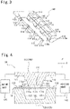
Fig. 1 is a perspective view of a metal-resin composite according to a first embodiment of the present invention; -
Fig. 2 is a cross-sectional view taken along line II-II inFig. 1 ; -
Fig. 3 is a perspective view of an upper mold according to the first embodiment; -
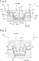
Fig. 4 is a cross-sectional view illustrating a first process of a method for producing the metal-resin composite in the first embodiment; -
Fig. 5 is a cross-sectional view illustrating a second process of the method for producing the metal-resin composite in the first embodiment; -
Fig. 6 is a cross-sectional view illustrating a third process of the method for producing the metal-resin composite in the first embodiment; -
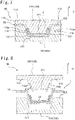
Fig. 7 is a cross-sectional view illustrating a fourth process of the method for producing the metal-resin composite in the first embodiment; -
Fig. 8 is a cross-sectional view illustrating a fifth process of the method for producing the metal-resin composite in the first embodiment; -
Fig. 9 is a cross-sectional view illustrating a first process of a method for producing a metal-resin composite in a second embodiment; -
Fig. 10 is a cross-sectional view illustrating a second process of the method for producing the metal-resin composite in the second embodiment; -
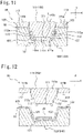
Fig. 11 is a cross-sectional view illustrating a third process of the method for producing the metal-resin composite in the second embodiment; -
Fig. 12 is a cross-sectional view illustrating a fourth process of the method for producing the metal-resin composite in the second embodiment; -
Fig. 13 is a cross-sectional view illustrating a fifth process of the method for producing the metal-resin composite in the second embodiment; -
Fig. 14 is a cross-sectional view illustrating a sixth process of the method for producing the metal-resin composite in the second embodiment; -
Fig. 15 is a cross-sectional view illustrating a seventh process of the method for producing the metal-resin composite in the second embodiment; -
Fig. 16 is a cross-sectional view illustrating a first process of a method for producing a metal-resin composite in a third embodiment; -
Fig. 17 is a cross-sectional view illustrating a second process of the method for producing the metal-resin composite in the third embodiment; -
Fig. 18 is a cross-sectional view illustrating a third process of the method for producing the metal-resin composite in the third embodiment; -
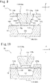
Fig. 19 is a cross-sectional view illustrating a fourth process of the method for producing the metal-resin composite in the third embodiment; and -
Fig. 20 is a cross-sectional view illustrating a fifth process of the method for producing the metal-resin composite in the third embodiment. - Hereinafter, a mold, an apparatus, and a method for producing a metal-resin composite will be described as an embodiment of the present invention with reference to the accompanying drawings.
- Referring to
Figs. 1 and 2 , a metal-resin composite 1 produced in the present embodiment includes a metal plate (metal member) 10 and aresin material 20. As illustrated inFig. 2 , the metal-resin composite 1 has a hat shape in a cross section perpendicular to a longitudinal direction. Specifically, the metal-resin composite 1 is formed by fixing theresin material 20 to an inner surface (recessed surface) of themetal plate 10 having a hat shape. However, the shape of the metal-resin composite 1 is not limited to a hat shape, and may be any shape. - The metal-
resin composite 1 includes abottom wall portion 2 extending in the horizontal direction,side wall portions 3 rising from both ends of thebottom wall portion 2, and aflange portion 4 extending outward in the horizontal direction from theside wall portion 3. Further, theside wall portion 3 is provided with astep portion 3a in which the thickness of theresin material 20 decreases from thebottom wall portion 2 toward theflange portion 4. Thebottom wall portion 2 includes themetal plate 10 and theresin material 20, theside wall portion 3 includes themetal plate 10 and theresin material 20, and theflange portion 4 includes only themetal plate 10. More specifically, theside wall portion 3 includes themetal plate 10 and theresin material 20 further on thebottom wall portion 2 side than thestep portion 3a, and includes only themetal plate 10 further on theflange portion 4 side than thestep portion 3a. - As illustrated in
Fig. 1 , thebottom wall portion 2 is provided with eight (only five inFig. 1 )holes 2a. Thehole 2a is a space where theresin material 20 does not exist. Four of theholes 2a are provided at each of both ends of thebottom wall portion 2 in a lateral direction. Further, theholes 2a are intermittently arranged along a longitudinal direction of thebottom wall portion 2. More specifically, theholes 2a are arranged side by side at equal intervals along the longitudinal direction of thebottom wall portion 2. - A
mold 100, anapparatus 50, and a method for producing the metal-resin composite 1 according to the present embodiment will be described with reference toFigs. 3 to 8 . In the drawings, the horizontal direction is indicated as an X direction, and the vertical direction is indicated as a Y direction. - In the present embodiment, press-forming is performed twice while first to fifth processes illustrated in
Figs. 4 to 8 are executed sequentially. First pressing is executed in the first to third processes illustrated inFigs. 4 to 6 , and second pressing is executed in the third to fifth processes illustrated inFigs. 6 to 8 . - Referring to
Fig. 4 , theapparatus 50 for producing the metal-resin composite 1 in the present embodiment includes themold 100, adrive unit 130 that drives themold 100, and aheating unit 140 that heats the mold. Note that, as thedrive unit 130 and theheating unit 140, publicly-known units capable of executing press-forming can be used, and details are not illustrated and a conceptual diagram is illustrated only inFig. 4 , and illustration is omitted inFig. 5 and subsequent figures. - The
mold 100 is for press-forming themetal plate 10 and theresin material 20 to produce the metal-resin composite 1. Themold 100 includes anupper mold 110 and alower mold 120 that sandwich themetal plate 10 and theresin material 20. In the present embodiment, theupper mold 110 is configured as a punch, and thelower mold 120 is configured as a die. Theupper mold 110 is movable in the vertical direction by thedrive unit 130, that is, is configured to be capable of approaching and separating from thelower mold 120. However, a driving mode of themold 100 by thedrive unit 130 is not particularly limited, and thedrive unit 130 can move at least one of theupper mold 110 and thelower mold 120 in the vertical direction. - Referring also to
Figs. 3 and 4 , theupper mold 110 has a first moldingupper surface 111 for molding the bottom wall portion 2 (seeFig. 1 ), a second moldingupper surface 112 for molding the side wall portion 3 (seeFig. 1 ), and a third moldingupper surface 113 for molding the flange portion 4 (seeFig. 1 ). In the present embodiment, the first moldingupper surface 111 and the third moldingupper surface 113 are configured as horizontal surfaces, and the second moldingupper surface 112 is configured to connect the first moldingupper surface 111 and the third moldingupper surface 113 and to be inclined from the vertical direction. - In the present embodiment, the
upper mold 110 is provided with eight protrudingportions 114 protruding downward from the first moldingupper surface 111. Four of the protrudingportions 114 are provided at each of both ends in the lateral direction of the first moldingupper surface 111. Further, the protrudingportions 114 are intermittently arranged along the longitudinal direction of theupper mold 110. More specifically, the protrudingportions 114 are arranged side by side at equal intervals along the longitudinal direction of theupper mold 110. - The first molding
upper surface 111 includes afirst press surface 111a provided at a lower end of the protrudingportion 114 and asecond press surface 111b provided above the protrudingportion 114. Thefirst press surface 111a and thesecond press surface 111b are configured as horizontal surfaces. Thefirst press surface 111a and thesecond press surface 111b are both provided continuously with the second moldingupper surface 112. - In the present embodiment, a
step 112a is provided on the second moldingupper surface 112. Thestep 112a is provided so as to rise one step from the first moldingupper surface 111 toward the third moldingupper surface 113. - The
lower mold 120 has a first moldinglower surface 121 for molding the bottom wall portion 2 (seeFig. 1 ), a second moldinglower surface 122 for molding the side wall portion 3 (seeFig. 1 ), and a third moldinglower surface 123 for molding the flange portion 4 (seeFig. 1 ). In the present embodiment, the first moldinglower surface 121 and the third moldinglower surface 123 are configured as horizontal surfaces, and the second moldinglower surface 122 is configured to connect the first moldinglower surface 121 and the third moldinglower surface 123 and to be inclined from the vertical direction. The first moldinglower surface 121 is arranged to face the first moldingupper surface 111, the second moldinglower surface 122 is arranged to face the second moldingupper surface 112, and the third moldinglower surface 123 is arranged to face the third moldingupper surface 113. - In a first process illustrated in
Fig. 4 , themetal plate 10 having a flat plate shape before molding is placed on thelower mold 120. - In a second process illustrated in
Fig. 5 , theupper mold 110 is lowered, and themetal plate 10 is sandwiched between theupper mold 110 and thelower mold 120 and press-formed into a substantially hat shape. In a state where theupper mold 110 and thelower mold 120 are closed, a distance d11 between thefirst press surface 111a of the first moldingupper surface 111 and the first moldinglower surface 121 is equal to a thickness t of the metal plate 10 (d11 = t). By setting the distance d11 equal to the thickness t of themetal plate 10, the molding accuracy of themetal plate 10 can be improved. Further, a distance d12 between thesecond press surface 111b of the first moldingupper surface 111 and the first moldinglower surface 121 is larger than the thickness t of the metal plate 10 (d12 > t), and a distance d3 between the third moldingupper surface 113 and the third moldinglower surface 123 is substantially equal to the thickness t of the metal plate 10 (d3 = t). A distance d21 between the second moldingupper surface 112 and the second moldinglower surface 122 below thestep 112a is larger than the thickness t of the metal plate 10 (d21 > t), and a distance d22 between the second moldingupper surface 112 and the second moldinglower surface 122 above thestep 112a is substantially equal to or slightly larger than the thickness t of the metal plate 10 (d22 = t or d22 > t). In particular, by setting the distance d22 equal to the thickness t of themetal plate 10, filling pressure of theresin material 20 in a subsequent process can be increased. Note that, in this process, the resin material 20 (seeFigs. 4 to 7 ) is not provided yet, and onlymetal plate 10 is sandwiched between theupper mold 110 and thelower mold 120. A cavity C to be filled with theresin material 20 is provided between the first and second moldingupper surfaces lower surfaces 121 and 122 (specifically, the metal plate 10). - In a third process illustrated in
Fig. 6 , theupper mold 110 is raised. At this time, themetal plate 10 is molded into a shape close to a final shape (a hat shape in the present embodiment). Then, theresin material 20 having a sheet-like shape (also referred to as prepreg) cut into a necessary size is placed on themetal plate 10. In the present embodiment, theresin material 20 is cured at a high temperature and a high pressure by a molding method called sheet molding compound (SMC) method (see the fourth process described later). In the present embodiment, as theresin material 20, a fiber reinforced plastic (FRP) in which a glass fiber or a carbon fiber is impregnated into resin is used. Further, in the present embodiment, theresin material 20 has a thermosetting property. In this process, theresin material 20 is not yet heated, that is, not cured. Note that theresin material 20 does not need to have a sheet-like shape, and can have any shape. - In a fourth process illustrated in
Fig. 7 , theupper mold 110 is lowered, and themetal plate 10 and theresin material 20 are sandwiched between theupper mold 110 and thelower mold 120 to be press-formed into a hat shape. At this time, the cavity C is filled with theresin material 20. That is, theresin material 20 cut to a necessary size is put into themold 100 and cured under high temperature and high pressure by the SMC method. In the present embodiment, the cavity C refers to a space below thestep 112a formed by being sandwiched between theupper mold 110 and the lower mold 120 (specifically, the metal plate 10). - When the cavity C is filled with the
resin material 20, theresin material 20 passes between the protruding portion 114 (illustrated inFig. 3 ) and the protrudingportion 114 of theupper mold 110 and flows into a space between the second moldingupper surface 112 and the second moldinglower surface 122. In this manner, theresin material 20 is included in the side wall portion 3 (illustrated inFig. 2 ), and thehole 2a (illustrated inFig. 1 ) is formed on the bottom wall portion 2 (illustrated inFig. 1 ) at a position corresponding to the protrudingportion 114. - In a fifth process illustrated in
Fig. 8 , theupper mold 110 is raised. Themetal plate 10 is molded into a final shape (a hat shape in the present embodiment), and theresin material 20 is fixed to an upper surface (a hat-shaped recessed surface) of themetal plate 10 so that the metal-resin composite 1 is formed. In this way, the metal-resin composite 1 having a hat shape is produced as a product. - In a case where press-forming of the
metal plate 10 and integral molding of themetal plate 10 and theresin material 20 are performed by a set of molds, when a mold in which a molding surface of an upper mold and a molding surface of a lower mold are separated from each other by a thickness of themetal plate 10 and theresin material 20 in a state where the upper mold and the lower mold are closed is used, themetal plate 10 cannot be pressed by the molding surface of the upper mold and the molding surface of the lower mold, and themetal plate 10 cannot be molded along a shape of the molding surface of the lower mold. In contrast, according to the present embodiment, since thefirst press surface 111a for molding themetal plate 10 is closer to the lower mold than thesecond press surface 111b for integrally molding themetal plate 10 and theresin material 20, themetal plate 10 easily follows the shape of thelower mold 120 during the press-forming of themetal plate 10. As a result, molding accuracy of themetal plate 10 can be improved. - Since the distance d11 between the
first press surface 111a and the first moldinglower surface 121 of thelower mold 120 is set to be at least partially equal to the thickness t of themetal plate 10, themetal plate 10 can be molded along the shape of the first moldinglower surface 121 of thelower mold 120. As a result, molding accuracy of themetal plate 10 can be improved. - Since the
first press surface 111a is provided continuously with the second moldingupper surface 112, the periphery of a corner portion formed by thebottom wall portion 2 and theside wall portion 3 of the metal-resin composite 1 can be pressed by thefirst press surface 111a, so that molding accuracy of the corner portion can be improved. - Since a plurality of the
first press surfaces 111a are intermittently arranged along the longitudinal direction, when themetal plate 10 and theresin material 20 are integrally molded, theresin material 20 flows between the second moldingupper surface 112 and themetal plate 10 through a portion where thefirst press surface 111a is not arranged. In this manner, theside wall portion 3 in which themetal plate 10 and theresin material 20 are integrally molded can be molded. - Since the
hole 2a is formed at a position corresponding to the protrudingportion 114 on thebottom wall portion 2 of the metal-resin composite 1 manufactured by themold 100 of the present embodiment, the weight of the metal-resin composite 1 can be reduced. Further, in the portion where thehole 2a is formed in thebottom wall portion 2, drilling or the like can be performed on themetal plate 10 without exclusion of theresin material 20. - The
mold 100, theapparatus 50, and the method for producing the metal-resin composite 1 according to a second embodiment will be described with reference toFigs. 9 to 15 . - In the present embodiment illustrated in
Figs. 9 to 15 , theupper mold 110 has a separatedpunch 110a and aholder 110b. The present embodiment is substantially the same as the first embodiment except for this. Therefore, the description of a portion illustrated in the first embodiment may be omitted. - In the present embodiment, the
upper mold 110 includes theholder 110b for pressing themetal plate 10 and thepunch 110a for molding. Theholder 110b and thepunch 110a are independently movable in the vertical direction by the drive unit 130 (seeFig. 2 ). - In the present embodiment, press-forming is executed twice while first to seventh processes illustrated in
Figs. 9 to 15 are executed sequentially. First pressing is executed in the first to fourth processes illustrated inFigs. 9 to 12 , and second pressing is executed in the fourth to seventh processes illustrated inFigs. 12 to 15 . - In the first pressing of the first to fourth processes illustrated in
Figs. 9 to 12 , unlike the first embodiment, theholder 110b descends prior to thepunch 110a to press themetal plate 10. Next, thepunch 110a descends to press-form themetal plate 10. The first to fourth processes of the present embodiment are substantially the same as the first to third processes of the first embodiment except that thepunch 110a and theholder 110b are independently driven as described above. - Also in the second pressing in the fourth to seventh processes illustrated in
Figs. 12 to 15 , unlike the first embodiment, theholder 110b descends prior to thepunch 110a to press themetal plate 10. Next, thepunch 110a descends to press-form themetal plate 10. The fourth to seventh processes of the present embodiment are substantially the same as the third to fifth processes of the first embodiment except that thepunch 110a and theholder 110b are independently driven as described above. - The
mold 100, theapparatus 50, and the method for producing the metal-resin composite 1 according to a third embodiment will be described with reference toFigs. 16 to 20 . - In the present embodiment illustrated in
Figs. 16 to 20 , theupper mold 110 has an upper moldmain body 115 and amovable portion 116. The present embodiment is substantially the same as the first embodiment except for this. Therefore, the description of a portion illustrated in the first embodiment may be omitted. - In the present embodiment, the
upper mold 110 has the upper moldmain body 115 on which thesecond press surface 111b is formed, and themovable portion 116 on which thefirst press surface 111a is formed and which is movably attached to the upper moldmain body 115. Themovable portion 116 is movable by a cylinder (not illustrated) to a protruding position where thefirst press surface 111a is closer to thelower mold 120 than thesecond press surface 111b and a retracting position where thefirst press surface 111a and thesecond press surface 111b are flush with each other. - In the present embodiment, press-forming is executed twice while first to fifth processes illustrated in
Figs. 16 to 20 are executed sequentially. First pressing is executed in the first to third processes illustrated inFigs. 16 to 18 , and second pressing is executed in the third to fifth processes illustrated inFigs. 18 to 20 . - In the first pressing of the first to fourth processes illustrated in
Figs. 16 to 18 , in the present embodiment, themetal plate 10 is press-formed in a state where themovable portion 116 is at the protruding position. The first to third processes of the present embodiment are substantially the same as the first to third processes of the first embodiment. - In the second pressing of the third to fifth processes illustrated in
Figs. 18 to 20 , unlike the first embodiment, themetal plate 10 and theresin material 20 are press-formed in a state where themovable portion 116 is at the retracting position. The second to fifth processes of the present embodiment are substantially the same as the third to fifth processes of the first embodiment except for the movement of themovable portion 116. - According to the present embodiment, the
metal plate 10 is press-formed in a state where themovable portion 116 is at the protruding position, and themetal plate 10 and theresin material 20 are integrally molded in a state where themovable portion 116 is at the retracting position, so that a portion from which theresin material 20 is removed is not formed in the molded metal-resin composite 1, and decrease in strength of the metal-resin composite 1 can be suppressed. - Although specific embodiments of the present invention and variations of the embodiments are described above, the present invention is not limited to the above embodiments, and various modifications can be made within the scope of the present invention. For example, an embodiment of the present invention may be obtained by appropriately combining the content of individual embodiments and variations.
- Further, as the
resin material 20, a thermoplastic resin impregnated with a glass fiber or a carbon fiber may be used. In this case, theresin material 20 is put into themold 100 in a state of being heated and softened. Then, theresin material 20 is cooled and cured on themetal plate 10 in themold 100 so that the metal-resin composite 1 is produced. - The
first press surface 111a of theupper mold 110 is provided at both ends in the lateral direction of the first moldingupper surface 111. However, the present invention is not limited to this. For example, thefirst press surface 111a may be provided in a central portion of the first moldingupper surface 111. In this case, molding accuracy in a central portion of thebottom wall portion 2 can be improved. Further, for example, thefirst press surface 111a may be provided at a position corresponding to a portion where drilling or the like into themetal plate 10 is required after the metal-resin composite 1 is integrally molded. In this case, in the portion, drilling or the like can be performed on themetal plate 10 without excluding theresin material 20. - In the metal-
resin composite 1, an adhesive layer may be provided between themetal plate 10 and theresin material 20. In this case, by providing the adhesive layer, themetal member 10 and theresin material 20 can be firmly integrally molded.
Claims (7)
- A mold for producing a metal-resin composite by press-forming a metal member and integrally molding the metal member that is press-formed and a resin material, the mold comprising:an upper mold and a lower mold that sandwich the metal member and the resin material,wherein the upper mold includes:a first press surface for press-forming the metal member; anda second press surface for integrally molding the metal member and the resin material, anda distance between the first press surface and the lower mold is shorter than a distance between the second press surface and the lower mold when the metal member is press-formed.
- The mold according to claim 1, wherein a distance between the first press surface and the lower mold is set to be at least partially equal to a thickness of the metal member in a state where the upper mold and the lower mold are closed.
- The mold according to claim 1 or 2, whereinthe metal-resin composite has a bottom wall portion extending in a horizontal direction and side wall portions rising from both ends of the bottom wall portion in a cross section perpendicular to a longitudinal direction of the metal-resin composite,the upper mold includes:a first molding upper surface that includes the first press surface and the second press surface, and molds the bottom wall portion; anda second molding upper surface that molds the side wall portion, andthe first press surface is provided continuously with the second molding upper surface.
- The mold according to claim 3, wherein a plurality of the first press surfaces is intermittently arranged along the longitudinal direction.
- The mold according to any one of claims 1 to 4, wherein
the upper mold includes:an upper mold main body on which the second press surface is formed; anda movable portion on which the first press surface is formed, the movable portion being movably attached to the upper mold main body, andthe movable portion is movable to a protruding position where the first press surface is closer to the lower mold than the second press surface and a retracting position where the first press surface and the second press surface are flush with each other. - An apparatus for producing a metal-resin composite by press-forming a metal member and integrally molding the metal member that is press-formed and a resin material, the apparatus comprising:an upper mold and a lower mold that sandwich the metal member and the resin material; anda drive unit that moves at least one of the upper mold and the lower mold in a vertical direction,wherein the upper mold includes:a first press surface for press-forming the metal member; anda second press surface for integrally molding the metal member and the resin material, anda distance between the first press surface and the lower mold is shorter than a distance between the second press surface and the lower mold when the metal member is press-formed.
- A method for producing a metal-resin composite by press-forming a metal member and integrally molding the metal member that is press-formed and a resin material, the method comprising:preparing an upper mold and a lower mold, the upper mold including a first press surface for press-forming the metal member and a second press surface for integrally molding the metal member and the resin material;press-forming the metal member with the first press surface of the upper mold and the lower mold by closing the upper mold and the lower mold;arranging the resin material on the metal member that is press-formed by opening the upper mold and the lower mold; andintegrally molding the metal member and the resin material with the second press surface of the upper mold and the lower mold by closing the upper mold and the lower mold,wherein a distance between the first press surface and the lower mold is shorter than a distance between the second press surface and the lower mold when the metal member is press-formed.
Applications Claiming Priority (1)
| Application Number | Priority Date | Filing Date | Title |
|---|---|---|---|
| JP2021097316A JP7638797B2 (en) | 2021-06-10 | 2021-06-10 | Mold, device, and method for manufacturing metal-resin composite |
Publications (1)
| Publication Number | Publication Date |
|---|---|
| EP4101616A1 true EP4101616A1 (en) | 2022-12-14 |
Family
ID=81877803
Family Applications (1)
| Application Number | Title | Priority Date | Filing Date |
|---|---|---|---|
| EP22174853.6A Pending EP4101616A1 (en) | 2021-06-10 | 2022-05-23 | Mold, apparatus, and method for producing metal-resin composite |
Country Status (4)
| Country | Link |
|---|---|
| US (1) | US12447700B2 (en) |
| EP (1) | EP4101616A1 (en) |
| JP (1) | JP7638797B2 (en) |
| CN (1) | CN115464824A (en) |
Families Citing this family (1)
| Publication number | Priority date | Publication date | Assignee | Title |
|---|---|---|---|---|
| KR20250118540A (en) * | 2024-01-30 | 2025-08-06 | 현대자동차주식회사 | Composite material parts forming apparatus |
Citations (6)
| Publication number | Priority date | Publication date | Assignee | Title |
|---|---|---|---|---|
| EP1506729A1 (en) * | 2002-05-22 | 2005-02-16 | Fiberpachs, Sa | Method and device for producing thermostable plastic parts with a textile covering comprising flexible vandal-proof areas and the part thus obtained |
| US20130082416A1 (en) * | 2011-10-04 | 2013-04-04 | E I Du Pont De Nemours And Company | Compression overmolding process, device therefor and part made therefrom |
| DE102015203642A1 (en) * | 2015-03-02 | 2016-09-08 | Bayerische Motoren Werke Aktiengesellschaft | Method for producing a component by forming a multilayer flat semi-finished product with a soft core layer and component produced therewith |
| US20170001407A1 (en) * | 2014-03-13 | 2017-01-05 | Aisin Takaoka Co., Ltd. | Composite structure and manufacturing method thereof |
| JP2020104411A (en) | 2018-12-27 | 2020-07-09 | 豊田鉄工株式会社 | Hot press machine and method for molding metal-resin composite |
| US10919284B2 (en) * | 2017-03-02 | 2021-02-16 | Volkswagen Aktiengesellschaft | Method for stiffening metal components by means of a robot-controlled application head |
Family Cites Families (8)
| Publication number | Priority date | Publication date | Assignee | Title |
|---|---|---|---|---|
| JPS491627B1 (en) * | 1969-09-19 | 1974-01-16 | ||
| US4555376A (en) * | 1984-03-12 | 1985-11-26 | Federal-Mogul Corporation | Molding an elastomeric ring while bonding it to a metal case and to a fluorocarbon washer |
| US9364979B2 (en) * | 2011-10-27 | 2016-06-14 | Toyota Boshoku Kabushiki Kaisha | Molded structure body and method of producing the same |
| JP5919066B2 (en) * | 2012-03-30 | 2016-05-18 | 富士重工業株式会社 | Monolithic molded part manufacturing method and monolithic molded part |
| DE102013105673B4 (en) | 2013-06-03 | 2017-01-05 | Benteler Automobiltechnik Gmbh | Press tool and method of making a fiber composite hybrid component |
| JP5929871B2 (en) * | 2013-10-17 | 2016-06-08 | トヨタ自動車株式会社 | Method for molding thermoplastic resin material |
| US12134218B2 (en) * | 2018-05-24 | 2024-11-05 | Nissan Motor Co., Ltd. | Method of forming component using metal-resin composite and mold for forming said component |
| JP7052571B2 (en) * | 2018-06-04 | 2022-04-12 | トヨタ自動車株式会社 | Molding equipment and manufacturing method of molded products |
-
2021
- 2021-06-10 JP JP2021097316A patent/JP7638797B2/en active Active
-
2022
- 2022-05-23 EP EP22174853.6A patent/EP4101616A1/en active Pending
- 2022-06-06 US US17/833,370 patent/US12447700B2/en active Active
- 2022-06-09 CN CN202210647473.5A patent/CN115464824A/en active Pending
Patent Citations (6)
| Publication number | Priority date | Publication date | Assignee | Title |
|---|---|---|---|---|
| EP1506729A1 (en) * | 2002-05-22 | 2005-02-16 | Fiberpachs, Sa | Method and device for producing thermostable plastic parts with a textile covering comprising flexible vandal-proof areas and the part thus obtained |
| US20130082416A1 (en) * | 2011-10-04 | 2013-04-04 | E I Du Pont De Nemours And Company | Compression overmolding process, device therefor and part made therefrom |
| US20170001407A1 (en) * | 2014-03-13 | 2017-01-05 | Aisin Takaoka Co., Ltd. | Composite structure and manufacturing method thereof |
| DE102015203642A1 (en) * | 2015-03-02 | 2016-09-08 | Bayerische Motoren Werke Aktiengesellschaft | Method for producing a component by forming a multilayer flat semi-finished product with a soft core layer and component produced therewith |
| US10919284B2 (en) * | 2017-03-02 | 2021-02-16 | Volkswagen Aktiengesellschaft | Method for stiffening metal components by means of a robot-controlled application head |
| JP2020104411A (en) | 2018-12-27 | 2020-07-09 | 豊田鉄工株式会社 | Hot press machine and method for molding metal-resin composite |
Also Published As
| Publication number | Publication date |
|---|---|
| JP7638797B2 (en) | 2025-03-04 |
| JP2022188995A (en) | 2022-12-22 |
| US12447700B2 (en) | 2025-10-21 |
| CN115464824A (en) | 2022-12-13 |
| US20220396041A1 (en) | 2022-12-15 |
Similar Documents
| Publication | Publication Date | Title |
|---|---|---|
| CN102873880B (en) | Composite panel, for the manufacture of the method and apparatus of composite panel | |
| JP6563284B2 (en) | Manufacturing apparatus for fiber-reinforced plastic molded product and manufacturing method thereof | |
| CN105073389B (en) | Composite structure of fiber-reinforced plastic plate and metal plate and manufacturing method thereof | |
| CN102105296A (en) | Device and method for the manufacture of three dimensional beam type elements in composite material | |
| CN213919414U (en) | Injection mold for demolding full-circle reverse-buckled products | |
| JP6137056B2 (en) | Manufacturing method of resin parts for automobile and manufacturing apparatus of resin parts for automobile | |
| US10814565B2 (en) | Mould arrangement and method for compression moulding fiber reinforced preforms | |
| JP2008055609A (en) | Uncured continuous preforming method for composites | |
| CN108778661B (en) | FRP sheet press forming method and apparatus, and FRP formed product | |
| EP4163081A1 (en) | Apparatus, mold set, and method for producing metal-resin composite | |
| US20170001339A1 (en) | Membrane-assisted preforming of plastic semi-finished product | |
| US12447700B2 (en) | Mold, apparatus, and method for producing metal-resin composite | |
| CN104822501A (en) | Molding method for thermoplastic resin material | |
| JPS6378717A (en) | Manufacture of composite member of metal plate and synthetic resin | |
| EP4101617A1 (en) | Mold, apparatus, and method for producing metal-resin composite | |
| JPWO2017068812A1 (en) | Manufacturing method of fiber reinforced resin structure, manufacturing system of fiber reinforced resin structure, and fiber reinforced resin structure | |
| EP4101615A1 (en) | Apparatus and method for producing metal-resin composite | |
| JP6709056B2 (en) | Method for manufacturing fiber-reinforced resin structure | |
| JP7755551B2 (en) | Metal-resin composite and method and apparatus for manufacturing the same | |
| CN203994444U (en) | The mould of dust catcher inner cover | |
| CN110509569B (en) | Integral curing and forming tool for longitudinal and transverse reinforced wallboard made of composite material | |
| CN216609773U (en) | Rudder forming mold | |
| CN215589856U (en) | Staggered tunnel core-pulling mold | |
| JP6726766B2 (en) | Molding method for fiber reinforced resin products | |
| CN117774226A (en) | A conformal continuous fiber reinforced composite structure and its forming mold and forming method |
Legal Events
| Date | Code | Title | Description |
|---|---|---|---|
| PUAI | Public reference made under article 153(3) epc to a published international application that has entered the european phase |
Free format text: ORIGINAL CODE: 0009012 |
|
| STAA | Information on the status of an ep patent application or granted ep patent |
Free format text: STATUS: REQUEST FOR EXAMINATION WAS MADE |
|
| 17P | Request for examination filed |
Effective date: 20220525 |
|
| AK | Designated contracting states |
Kind code of ref document: A1 Designated state(s): AL AT BE BG CH CY CZ DE DK EE ES FI FR GB GR HR HU IE IS IT LI LT LU LV MC MK MT NL NO PL PT RO RS SE SI SK SM TR |
|
| RBV | Designated contracting states (corrected) |
Designated state(s): AL AT BE BG CH CY CZ DE DK EE ES FI FR GB GR HR HU IE IS IT LI LT LU LV MC MK MT NL NO PL PT RO RS SE SI SK SM TR |
|
| STAA | Information on the status of an ep patent application or granted ep patent |
Free format text: STATUS: EXAMINATION IS IN PROGRESS |
|
| 17Q | First examination report despatched |
Effective date: 20250811 |