EP4101523A1 - Slurry storage device, slurry production system and slurry storage method - Google Patents
Slurry storage device, slurry production system and slurry storage method Download PDFInfo
- Publication number
- EP4101523A1 EP4101523A1 EP20917538.9A EP20917538A EP4101523A1 EP 4101523 A1 EP4101523 A1 EP 4101523A1 EP 20917538 A EP20917538 A EP 20917538A EP 4101523 A1 EP4101523 A1 EP 4101523A1
- Authority
- EP
- European Patent Office
- Prior art keywords
- slurry
- value
- storage device
- holding means
- high nickel
- Prior art date
- Legal status (The legal status is an assumption and is not a legal conclusion. Google has not performed a legal analysis and makes no representation as to the accuracy of the status listed.)
- Granted
Links
Images




Classifications
-
- B—PERFORMING OPERATIONS; TRANSPORTING
- B01—PHYSICAL OR CHEMICAL PROCESSES OR APPARATUS IN GENERAL
- B01F—MIXING, e.g. DISSOLVING, EMULSIFYING OR DISPERSING
- B01F25/00—Flow mixers; Mixers for falling materials, e.g. solid particles
- B01F25/50—Circulation mixers, e.g. wherein at least part of the mixture is discharged from and reintroduced into a receptacle
-
- B—PERFORMING OPERATIONS; TRANSPORTING
- B01—PHYSICAL OR CHEMICAL PROCESSES OR APPARATUS IN GENERAL
- B01F—MIXING, e.g. DISSOLVING, EMULSIFYING OR DISPERSING
- B01F23/00—Mixing according to the phases to be mixed, e.g. dispersing or emulsifying
- B01F23/50—Mixing liquids with solids
- B01F23/51—Methods thereof
- B01F23/511—Methods thereof characterised by the composition of the liquids or solids
-
- B—PERFORMING OPERATIONS; TRANSPORTING
- B01—PHYSICAL OR CHEMICAL PROCESSES OR APPARATUS IN GENERAL
- B01F—MIXING, e.g. DISSOLVING, EMULSIFYING OR DISPERSING
- B01F23/00—Mixing according to the phases to be mixed, e.g. dispersing or emulsifying
- B01F23/50—Mixing liquids with solids
- B01F23/53—Mixing liquids with solids using driven stirrers
-
- B—PERFORMING OPERATIONS; TRANSPORTING
- B01—PHYSICAL OR CHEMICAL PROCESSES OR APPARATUS IN GENERAL
- B01F—MIXING, e.g. DISSOLVING, EMULSIFYING OR DISPERSING
- B01F23/00—Mixing according to the phases to be mixed, e.g. dispersing or emulsifying
- B01F23/50—Mixing liquids with solids
- B01F23/59—Mixing systems, i.e. flow charts or diagrams
-
- B—PERFORMING OPERATIONS; TRANSPORTING
- B01—PHYSICAL OR CHEMICAL PROCESSES OR APPARATUS IN GENERAL
- B01F—MIXING, e.g. DISSOLVING, EMULSIFYING OR DISPERSING
- B01F25/00—Flow mixers; Mixers for falling materials, e.g. solid particles
- B01F25/50—Circulation mixers, e.g. wherein at least part of the mixture is discharged from and reintroduced into a receptacle
- B01F25/53—Circulation mixers, e.g. wherein at least part of the mixture is discharged from and reintroduced into a receptacle in which the mixture is discharged from and reintroduced into a receptacle through a recirculation tube, into which an additional component is introduced
-
- B—PERFORMING OPERATIONS; TRANSPORTING
- B01—PHYSICAL OR CHEMICAL PROCESSES OR APPARATUS IN GENERAL
- B01F—MIXING, e.g. DISSOLVING, EMULSIFYING OR DISPERSING
- B01F33/00—Other mixers; Mixing plants; Combinations of mixers
- B01F33/40—Mixers using gas or liquid agitation, e.g. with air supply tubes
- B01F33/402—Mixers using gas or liquid agitation, e.g. with air supply tubes comprising supplementary stirring elements
-
- B—PERFORMING OPERATIONS; TRANSPORTING
- B01—PHYSICAL OR CHEMICAL PROCESSES OR APPARATUS IN GENERAL
- B01F—MIXING, e.g. DISSOLVING, EMULSIFYING OR DISPERSING
- B01F33/00—Other mixers; Mixing plants; Combinations of mixers
- B01F33/40—Mixers using gas or liquid agitation, e.g. with air supply tubes
- B01F33/407—Mixers using gas or liquid agitation, e.g. with air supply tubes by blowing gas on the material from above
-
- B—PERFORMING OPERATIONS; TRANSPORTING
- B01—PHYSICAL OR CHEMICAL PROCESSES OR APPARATUS IN GENERAL
- B01F—MIXING, e.g. DISSOLVING, EMULSIFYING OR DISPERSING
- B01F35/00—Accessories for mixers; Auxiliary operations or auxiliary devices; Parts or details of general application
- B01F35/20—Measuring; Control or regulation
- B01F35/21—Measuring
- B01F35/211—Measuring of the operational parameters
- B01F35/2113—Pressure
-
- B—PERFORMING OPERATIONS; TRANSPORTING
- B01—PHYSICAL OR CHEMICAL PROCESSES OR APPARATUS IN GENERAL
- B01F—MIXING, e.g. DISSOLVING, EMULSIFYING OR DISPERSING
- B01F35/00—Accessories for mixers; Auxiliary operations or auxiliary devices; Parts or details of general application
- B01F35/20—Measuring; Control or regulation
- B01F35/22—Control or regulation
- B01F35/221—Control or regulation of operational parameters, e.g. level of material in the mixer, temperature or pressure
- B01F35/2213—Pressure
-
- B—PERFORMING OPERATIONS; TRANSPORTING
- B01—PHYSICAL OR CHEMICAL PROCESSES OR APPARATUS IN GENERAL
- B01F—MIXING, e.g. DISSOLVING, EMULSIFYING OR DISPERSING
- B01F35/00—Accessories for mixers; Auxiliary operations or auxiliary devices; Parts or details of general application
- B01F35/20—Measuring; Control or regulation
- B01F35/22—Control or regulation
- B01F35/221—Control or regulation of operational parameters, e.g. level of material in the mixer, temperature or pressure
- B01F35/2215—Temperature
-
- B—PERFORMING OPERATIONS; TRANSPORTING
- B01—PHYSICAL OR CHEMICAL PROCESSES OR APPARATUS IN GENERAL
- B01F—MIXING, e.g. DISSOLVING, EMULSIFYING OR DISPERSING
- B01F35/00—Accessories for mixers; Auxiliary operations or auxiliary devices; Parts or details of general application
- B01F35/71—Feed mechanisms
- B01F35/717—Feed mechanisms characterised by the means for feeding the components to the mixer
- B01F35/7173—Feed mechanisms characterised by the means for feeding the components to the mixer using gravity, e.g. from a hopper
- B01F35/71731—Feed mechanisms characterised by the means for feeding the components to the mixer using gravity, e.g. from a hopper using a hopper
-
- B—PERFORMING OPERATIONS; TRANSPORTING
- B01—PHYSICAL OR CHEMICAL PROCESSES OR APPARATUS IN GENERAL
- B01F—MIXING, e.g. DISSOLVING, EMULSIFYING OR DISPERSING
- B01F35/00—Accessories for mixers; Auxiliary operations or auxiliary devices; Parts or details of general application
- B01F35/71—Feed mechanisms
- B01F35/717—Feed mechanisms characterised by the means for feeding the components to the mixer
- B01F35/7176—Feed mechanisms characterised by the means for feeding the components to the mixer using pumps
-
- B—PERFORMING OPERATIONS; TRANSPORTING
- B01—PHYSICAL OR CHEMICAL PROCESSES OR APPARATUS IN GENERAL
- B01F—MIXING, e.g. DISSOLVING, EMULSIFYING OR DISPERSING
- B01F35/00—Accessories for mixers; Auxiliary operations or auxiliary devices; Parts or details of general application
- B01F35/71—Feed mechanisms
- B01F35/717—Feed mechanisms characterised by the means for feeding the components to the mixer
- B01F35/71805—Feed mechanisms characterised by the means for feeding the components to the mixer using valves, gates, orifices or openings
-
- B—PERFORMING OPERATIONS; TRANSPORTING
- B01—PHYSICAL OR CHEMICAL PROCESSES OR APPARATUS IN GENERAL
- B01F—MIXING, e.g. DISSOLVING, EMULSIFYING OR DISPERSING
- B01F35/00—Accessories for mixers; Auxiliary operations or auxiliary devices; Parts or details of general application
- B01F35/90—Heating or cooling systems
-
- B—PERFORMING OPERATIONS; TRANSPORTING
- B01—PHYSICAL OR CHEMICAL PROCESSES OR APPARATUS IN GENERAL
- B01J—CHEMICAL OR PHYSICAL PROCESSES, e.g. CATALYSIS OR COLLOID CHEMISTRY; THEIR RELEVANT APPARATUS
- B01J19/00—Chemical, physical or physico-chemical processes in general; Their relevant apparatus
- B01J19/0053—Details of the reactor
- B01J19/0066—Stirrers
-
- B—PERFORMING OPERATIONS; TRANSPORTING
- B01—PHYSICAL OR CHEMICAL PROCESSES OR APPARATUS IN GENERAL
- B01J—CHEMICAL OR PHYSICAL PROCESSES, e.g. CATALYSIS OR COLLOID CHEMISTRY; THEIR RELEVANT APPARATUS
- B01J19/00—Chemical, physical or physico-chemical processes in general; Their relevant apparatus
- B01J19/18—Stationary reactors having moving elements inside
-
- B—PERFORMING OPERATIONS; TRANSPORTING
- B01—PHYSICAL OR CHEMICAL PROCESSES OR APPARATUS IN GENERAL
- B01J—CHEMICAL OR PHYSICAL PROCESSES, e.g. CATALYSIS OR COLLOID CHEMISTRY; THEIR RELEVANT APPARATUS
- B01J8/00—Chemical or physical processes in general, conducted in the presence of fluids and solid particles; Apparatus for such processes
- B01J8/0015—Feeding of the particles in the reactor; Evacuation of the particles out of the reactor
- B01J8/004—Feeding of the particles in the reactor; Evacuation of the particles out of the reactor by means of a nozzle
-
- B—PERFORMING OPERATIONS; TRANSPORTING
- B65—CONVEYING; PACKING; STORING; HANDLING THIN OR FILAMENTARY MATERIAL
- B65D—CONTAINERS FOR STORAGE OR TRANSPORT OF ARTICLES OR MATERIALS, e.g. BAGS, BARRELS, BOTTLES, BOXES, CANS, CARTONS, CRATES, DRUMS, JARS, TANKS, HOPPERS, FORWARDING CONTAINERS; ACCESSORIES, CLOSURES, OR FITTINGS THEREFOR; PACKAGING ELEMENTS; PACKAGES
- B65D81/00—Containers, packaging elements, or packages, for contents presenting particular transport or storage problems, or adapted to be used for non-packaging purposes after removal of contents
- B65D81/18—Containers, packaging elements, or packages, for contents presenting particular transport or storage problems, or adapted to be used for non-packaging purposes after removal of contents providing specific environment for contents, e.g. temperature above or below ambient
-
- B—PERFORMING OPERATIONS; TRANSPORTING
- B65—CONVEYING; PACKING; STORING; HANDLING THIN OR FILAMENTARY MATERIAL
- B65D—CONTAINERS FOR STORAGE OR TRANSPORT OF ARTICLES OR MATERIALS, e.g. BAGS, BARRELS, BOTTLES, BOXES, CANS, CARTONS, CRATES, DRUMS, JARS, TANKS, HOPPERS, FORWARDING CONTAINERS; ACCESSORIES, CLOSURES, OR FITTINGS THEREFOR; PACKAGING ELEMENTS; PACKAGES
- B65D90/00—Component parts, details or accessories for large containers
-
- B—PERFORMING OPERATIONS; TRANSPORTING
- B65—CONVEYING; PACKING; STORING; HANDLING THIN OR FILAMENTARY MATERIAL
- B65D—CONTAINERS FOR STORAGE OR TRANSPORT OF ARTICLES OR MATERIALS, e.g. BAGS, BARRELS, BOTTLES, BOXES, CANS, CARTONS, CRATES, DRUMS, JARS, TANKS, HOPPERS, FORWARDING CONTAINERS; ACCESSORIES, CLOSURES, OR FITTINGS THEREFOR; PACKAGING ELEMENTS; PACKAGES
- B65D90/00—Component parts, details or accessories for large containers
- B65D90/22—Safety features
- B65D90/32—Arrangements for preventing, or minimising the effect of, excessive or insufficient pressure
-
- H—ELECTRICITY
- H01—ELECTRIC ELEMENTS
- H01M—PROCESSES OR MEANS, e.g. BATTERIES, FOR THE DIRECT CONVERSION OF CHEMICAL ENERGY INTO ELECTRICAL ENERGY
- H01M4/00—Electrodes
- H01M4/02—Electrodes composed of, or comprising, active material
- H01M4/13—Electrodes for accumulators with non-aqueous electrolyte, e.g. for lithium-accumulators; Processes of manufacture thereof
- H01M4/139—Processes of manufacture
-
- H—ELECTRICITY
- H01—ELECTRIC ELEMENTS
- H01M—PROCESSES OR MEANS, e.g. BATTERIES, FOR THE DIRECT CONVERSION OF CHEMICAL ENERGY INTO ELECTRICAL ENERGY
- H01M4/00—Electrodes
- H01M4/02—Electrodes composed of, or comprising, active material
- H01M4/36—Selection of substances as active materials, active masses, active liquids
- H01M4/48—Selection of substances as active materials, active masses, active liquids of inorganic oxides or hydroxides
- H01M4/52—Selection of substances as active materials, active masses, active liquids of inorganic oxides or hydroxides of nickel, cobalt or iron
- H01M4/525—Selection of substances as active materials, active masses, active liquids of inorganic oxides or hydroxides of nickel, cobalt or iron of mixed oxides or hydroxides containing iron, cobalt or nickel for inserting or intercalating light metals, e.g. LiNiO2, LiCoO2 or LiCoOxFy
-
- B—PERFORMING OPERATIONS; TRANSPORTING
- B01—PHYSICAL OR CHEMICAL PROCESSES OR APPARATUS IN GENERAL
- B01F—MIXING, e.g. DISSOLVING, EMULSIFYING OR DISPERSING
- B01F35/00—Accessories for mixers; Auxiliary operations or auxiliary devices; Parts or details of general application
- B01F35/90—Heating or cooling systems
- B01F2035/98—Cooling
-
- B—PERFORMING OPERATIONS; TRANSPORTING
- B01—PHYSICAL OR CHEMICAL PROCESSES OR APPARATUS IN GENERAL
- B01F—MIXING, e.g. DISSOLVING, EMULSIFYING OR DISPERSING
- B01F35/00—Accessories for mixers; Auxiliary operations or auxiliary devices; Parts or details of general application
- B01F35/90—Heating or cooling systems
- B01F2035/99—Heating
-
- B—PERFORMING OPERATIONS; TRANSPORTING
- B01—PHYSICAL OR CHEMICAL PROCESSES OR APPARATUS IN GENERAL
- B01F—MIXING, e.g. DISSOLVING, EMULSIFYING OR DISPERSING
- B01F2101/00—Mixing characterised by the nature of the mixed materials or by the application field
- B01F2101/59—Mixing reaction ingredients for fuel cells
-
- B—PERFORMING OPERATIONS; TRANSPORTING
- B01—PHYSICAL OR CHEMICAL PROCESSES OR APPARATUS IN GENERAL
- B01J—CHEMICAL OR PHYSICAL PROCESSES, e.g. CATALYSIS OR COLLOID CHEMISTRY; THEIR RELEVANT APPARATUS
- B01J2208/00—Processes carried out in the presence of solid particles; Reactors therefor
- B01J2208/00008—Controlling the process
- B01J2208/00592—Controlling the pH
-
- B—PERFORMING OPERATIONS; TRANSPORTING
- B01—PHYSICAL OR CHEMICAL PROCESSES OR APPARATUS IN GENERAL
- B01J—CHEMICAL OR PHYSICAL PROCESSES, e.g. CATALYSIS OR COLLOID CHEMISTRY; THEIR RELEVANT APPARATUS
- B01J2208/00—Processes carried out in the presence of solid particles; Reactors therefor
- B01J2208/00743—Feeding or discharging of solids
- B01J2208/00769—Details of feeding or discharging
- B01J2208/00787—Bringing the solid in the form of a slurry before feeding it to the reactor
-
- Y—GENERAL TAGGING OF NEW TECHNOLOGICAL DEVELOPMENTS; GENERAL TAGGING OF CROSS-SECTIONAL TECHNOLOGIES SPANNING OVER SEVERAL SECTIONS OF THE IPC; TECHNICAL SUBJECTS COVERED BY FORMER USPC CROSS-REFERENCE ART COLLECTIONS [XRACs] AND DIGESTS
- Y02—TECHNOLOGIES OR APPLICATIONS FOR MITIGATION OR ADAPTATION AGAINST CLIMATE CHANGE
- Y02E—REDUCTION OF GREENHOUSE GAS [GHG] EMISSIONS, RELATED TO ENERGY GENERATION, TRANSMISSION OR DISTRIBUTION
- Y02E60/00—Enabling technologies; Technologies with a potential or indirect contribution to GHG emissions mitigation
- Y02E60/10—Energy storage using batteries
-
- Y—GENERAL TAGGING OF NEW TECHNOLOGICAL DEVELOPMENTS; GENERAL TAGGING OF CROSS-SECTIONAL TECHNOLOGIES SPANNING OVER SEVERAL SECTIONS OF THE IPC; TECHNICAL SUBJECTS COVERED BY FORMER USPC CROSS-REFERENCE ART COLLECTIONS [XRACs] AND DIGESTS
- Y02—TECHNOLOGIES OR APPLICATIONS FOR MITIGATION OR ADAPTATION AGAINST CLIMATE CHANGE
- Y02P—CLIMATE CHANGE MITIGATION TECHNOLOGIES IN THE PRODUCTION OR PROCESSING OF GOODS
- Y02P70/00—Climate change mitigation technologies in the production process for final industrial or consumer products
- Y02P70/50—Manufacturing or production processes characterised by the final manufactured product
Definitions
- the present invention relates to a slurry storage device, a slurry production system, and a slurry storage method. More specifically, the present invention relates to the slurry storage device, the slurry production system, and the slurry storage method for an aqueous slurry containing a high nickel material.
- a lithium ion secondary battery having a high energy density, a high operating voltage, and being capable of downsizing and weight saving is widely used.
- the lithium ion secondary battery is a secondary battery (storage battery) that uses lithium ion as an ion responsible for electrical conduction, and means a power storage device called, for example, a lithium ion battery, a lithium secondary battery, a lithium all-solid-state battery, a lithium polymer battery, a lithium gel battery, or the like.
- a lithium transition metal composite oxide containing a transition metal such as nickel, cobalt, and manganese is known.
- a material having a particularly high nickel content is called a high nickel material, and is attracting attention as a positive electrode active material capable of stably extracting a high electric capacity.
- PTL 1 describes an aqueous slurry in which an aqueous solution containing a specific binder component and an electrochemically activating compound (containing a positive electrode active material) are mixed as a slurry for producing an electrode.
- the prepared slurry may be temporarily stored and then subjected to the coating process.
- the present inventors have found that, in particular, when storing an aqueous slurry containing a high nickel material, the pH value of the slurry rises with the passage of time, and the physical properties of the slurry deteriorate.
- the pH value of the slurry rises, there is a problem that the current collector coated with the slurry is corroded in the coating process, which is a next process .
- the coating itself on the current collector is difficult due to the deterioration of the physical properties of the slurry.
- An object of the present invention is to provide a slurry storage device, a slurry production system, and a slurry storage method capable of appropriately storing an aqueous slurry containing a particularly high nickel material among aqueous slurries.
- aqueous slurry particularly containing a high nickel material among the aqueous slurries can be appropriately stored by providing pH value rise suppressing means for suppressing a rise in the pH value of the slurry with respect to holding means for holding the slurry.
- the present invention is a slurry storage device, a slurry production system, and a slurry storage method as follows.
- a slurry storage device that stores an aqueous slurry containing a high nickel material prepared by a dispersion device which mixes a powder and a solvent, the device including a holding means that holds the aqueous slurry containing the high nickel material, and a pH value rise suppressing means that suppresses a rise in a pH value of the aqueous slurry containing the high nickel material.
- the pH value rise suppressing means that suppresses the rise in the pH value of the aqueous slurry containing the high nickel material, it is possible to suppress alkalization (pH value rise) of the aqueous slurry containing the high nickel material held in the holding means due to a time-dependent change and suppress deterioration of the physical properties of the slurry. As a result, it is possible to stably store the aqueous slurry containing the high nickel material for a long period of time.
- the pH value rise suppressing means includes a pressurizing means using supply of a pressurized gas.
- the slurry in the holding means is alkalized by coming into contact with the moisture in the outside air.
- the slurry in the holding means does not react with the moisture in the outside air, the rise in the pH value of the slurry can be easily suppressed, and the stable storage of the aqueous slurry containing the high nickel material can be easily performed.
- the pressurized gas supplied by the pressurizing means is a gas containing carbon dioxide (carbon dioxide gas).
- a neutralization reaction (2LiOH + CO 2 ⁇ Li 2 CO 3 + H 2 O) occurs between the acid component generated by dissolving carbon dioxide (carbon dioxide gas, CO 2 ) in water and the alkaline component in the slurry on the surface of the slurry contained in the holding means.
- carbon dioxide gas, CO 2 carbon dioxide gas
- the pH value rise suppressing means includes a dry air supply means that supplies dry air.
- the pH value rise suppressing means includes a decompression means.
- the gas component in the holding means can be removed by reducing the pressure in the holding means.
- the gas component it is possible to reduce the moisture in the gas in the holding means.
- the reaction between the slurry and the moisture in the holding means can be suppressed, the rise in the pH value of the slurry can be easily suppressed, and the stable storage of the aqueous slurry containing the high nickel material can be easily performed.
- a pressure sensor is provided in the holding means, and the slurry storage device further includes a pressure regulating means that regulates a pressure in the holding means based on a value of the pressure sensor.
- a slurry production system including the above-described slurry storage device; and a dispersion device that prepares an aqueous slurry containing a high nickel material.
- the slurry prepared by the dispersion device can be stably stored in a state where alkalization and deterioration of physical properties of the slurry are suppressed until the slurry is transferred to the next process (coating process) .
- the slurry is transferred to the next process (coating process) .
- a slurry storage method of storing an aqueous slurry containing a high nickel material prepared by a dispersion device which mixes a powder and a solvent the method including a holding step of holding the aqueous slurry containing the high nickel material, and a pH value rise suppressing step of suppressing a rise in a pH value of the aqueous slurry containing the high nickel material.
- the pH value rise suppressing step of suppressing the rise in the pH value of the aqueous slurry containing the high nickel material it is possible to suppress alkalization of the aqueous slurry containing the high nickel material held by the holding step due to a time-dependent change and suppress deterioration of the physical properties of the slurry. As a result, it is possible to stably store the aqueous slurry containing the high nickel material for a long period of time.
- a slurry storage device capable of appropriately storing an aqueous slurry containing a particularly high nickel material among the aqueous slurries.
- the slurry storage device and the slurry production system described in the embodiment are merely exemplified for describing the slurry storage device and the slurry production system according to the present invention, and the present invention is not limited thereto.
- the slurry storage method of the present invention is replaced with the following description of a structure and operation of the slurry storage device.
- Slurry S to be stored in the present invention is an aqueous slurry containing a lithium transition metal composite oxide used as a positive electrode active material for a lithium ion secondary battery.
- examples thereof include an aqueous slurry containing a so-called high nickel material having a particularly high nickel content in a transition metal composite oxide containing lithium.
- the high nickel material means a layered oxide-based material containing lithium in which Ni exceeds 0.5 in a case where the transition metal element in the positive electrode active material is 1.
- a positive electrode active material having Ni of less than 0.5 is produced by firing in air using lithium carbonate, a transition metal hydroxide or the like as raw materials. Therefore, the positive electrode active material contains substantially no lithium hydroxide having high reactivity.
- a positive electrode active material with Ni of 0.5 or more is produced by firing in oxygen using highly reactive lithium hydroxide, transition metal hydroxides, transition metal oxyhydroxides or the like as raw materials. Therefore, the positive electrode active material contains a large amount of highly reactive lithium hydroxide.
- a positive electrode active material having Ni of 0.5 or more is likely to generate lithium hydroxide by a proton exchange reaction. Therefore, it is considered that such a high nickel material is likely to be alkalized with the passage of time during storage in a case where the high nickel material is prepared as an aqueous slurry using water as a solvent or a dispersion medium.
- Examples of the high nickel material include LiNiO 2 , Li(Ni 0.6 Co 0.4 )O 2 , Li(Ni 0.8 Co 0.2 )O 2 , Li(Ni 0.8 Co 0.15 Al 0.05 )O 2 , Li(Ni 0.6 Co 0.2 Mn 0.2 )O 2 , Li(Ni 0.8 Co 0.1 Mn 0.1 )O 2 , Li(Ni 0.9 Co 0.05 Mn 0.05 )O 2 , and the like.
- Examples thereof include a material in which another alkali metal atom replaces a part of the lithium atom site, a material in which a fluorine atom replaces a part of the oxygen atom site of a high nickel material, a material in which an aluminum atom replaces a part of the transition metal atom sites of a high nickel material, and the like.
- Fig. 1 is a schematic explanatory view illustrating a structure of a slurry production system according to the first embodiment of the present invention.
- a slurry production system 100 is provided with a dispersion device 1 and a slurry storage device 2A.
- the slurry S is first prepared in the dispersion device 1, and then the prepared slurry S is stored in the slurry storage device 2A. Thereafter, the stored slurry S is transferred from the slurry storage device 2A to a place where the next process is performed according to the timing when the next process (mainly the coating process) is performed.
- the dispersion device 1 may be any device as long as a device can prepare an aqueous slurry containing a high nickel material as the slurry S, and the details of the device configuration are not particularly limited.
- the dispersion device 1 in the present embodiment refers to a device capable of mixing at least a solid (powder) and a liquid (solvent) to prepare a slurry which is a mixture of a granular solid matter and a liquid, and also includes a device called a mixing device, a kneading device, and the like.
- the dispersion device 1 in the present embodiment has a configuration capable of mixing a gas as well. As a result, it is possible to suppress the alkalization of the slurry S at the time of preparation.
- Examples of the raw material of the slurry S to be charged into the dispersion device 1 include powder of a positive electrode active material used in a lithium ion secondary battery (hereinafter, simply referred to as a "powder P"), solvent W (water), a binder, a conductive material, and the like.
- a positive electrode active material it is preferable to use a lithium transition metal composite oxide known as a high nickel material.
- the binder, the conductive material and the like are appropriately used as needed, and the specific substance is not particularly limited. A known substance can be used in the preparation of the aqueous slurry.
- a gas such as carbon dioxide (carbon dioxide gas) or an inert gas may be supplied to the dispersion device 1.
- a gas containing carbon dioxide (carbon dioxide gas) to the dispersion device 1.
- carbon dioxide gas More preferably, it is preferable to supply only carbon dioxide (carbon dioxide gas) to the dispersion device 1.
- the high nickel material is not contained, lithium hydroxide is not contained in the slurry. Therefore, by supplying carbon dioxide (carbon dioxide gas), the pH value of the aqueous slurry is low (pH value is less than 5), and the transition metal may be dissolved with acid. In the slurry in which the transition metal is dissolved in this manner, the metal may re-precipitate during charging and discharging. In addition, it is not preferable because the discharge capacity of the positive electrode active material is small and stable cycle characteristics cannot be obtained.
- carbon dioxide carbon dioxide gas
- the pH value is an index indicating the hydrogen ion concentration. That is, in a case where the pH value is less than 7, it is acidic, and in a case where the pH value exceeds 7, it is alkaline.
- the pH value is a value measured by a pH meter, but as another method, the pH value may be determined by an indicator method or the like.
- Fig. 1 illustrates the dispersion device 1 including a powder supply unit 10, a stirring tank 11, a circulation liquid feed pump 12, and a dispersion unit 13.
- the dispersion device 1 illustrated in Fig. 1 illustrates an example of the dispersion device 1 in the present embodiment, and is not limited to the configuration illustrated in Fig. 1 .
- the powder supply unit 10 charges a solid component (powder P) of the raw materials of the slurry S into the dispersion unit 13.
- a known structure can be used in the dispersion device for charging the solid component, and the structure is not particularly limited.
- a hopper 10a having an upper opening portion and a lower opening portion may be provided and installed so that the powder P is charged from the upper opening portion and is supplied from the lower opening portion to the dispersion unit 13 via a line L1.
- various incidental mechanisms may be provided on the powder supply unit 10 and the line L1.
- an incidental mechanism include a stirring mechanism for stirring the powder P in the powder supply unit 10, a quantitative supply mechanism for quantitatively supplying the powder P from the powder supply unit 10 to the dispersion unit 13, a vibrator or a kicker for removing the powder P adhering to the powder supply unit 10, and the like.
- the stirring tank 11 supplies the liquid component (solvent W) of the raw materials of the slurry S to the dispersion unit 13.
- the stirring tank 11 is connected to the dispersion unit 13 in a circulatable manner and stores the prepared slurry S.
- a known structure for supplying the liquid component and storing the slurry in the dispersion device can be used, and is not particularly limited.
- a tank main body 11a and a stirring device 11b inside the tank main body 11a are provided and are connected to the dispersion unit 13 in a circulatable manner via a line L2 and a line L3.
- the tank main body 11a may be provided with a line L4 for supplying the solvent W (water) from the outside and a line L5 for exhausting the contents (solvent W or slurry S) in the tank main body 11a to the outside of the system.
- the stirring tank 11 can be used also as holding means 3 of the slurry storage device 2A. A description of common use of the holding means 3 of the slurry storage device 2A and the stirring tank 11 will be described later.
- the circulation liquid feed pump 12 is for controlling the flow directions of the solvent W and the slurry S in the dispersion device 1 and regulating the flow rate.
- a pump capable of sucking the solvent W and the slurry S in the stirring tank 11 and delivering the solvent W and the slurry S toward the dispersion unit 13 may be provided on the line L2.
- the solvent W and the slurry S circulate between the stirring tank 11 and the dispersion unit 13, and the dispersion treatment in the dispersion unit 13 can be repeated, so that it is possible to homogenize the dispersion of the powder P with respect to the solvent W.
- the dispersion unit 13 is for preparing a slurry S by mixing and dispersing a solid component (powder P) and a liquid component (solvent W).
- the dispersion unit 13 one having a configuration that disperses by ultrasonic waves, one having a configuration that disperses by shearing force, such as a planetary mixer and a twin-screw kneader, one having a configuration that disperses by cavitation and shearing force, and the like may be used.
- a kneading process is not required and excessive pulverization of the positive electrode active material is unlikely to occur
- examples of those that disperse by cavitation and shearing force include "JET PASTER (registered trademark)" manufactured by Nihon Spindle Manufacturing Co., Ltd. as a commercially available product.
- the powder P and the solvent W are supplied to the dispersion unit 13 from the powder supply unit 10 and the stirring tank 11 via the lines L1 and L2.
- Means for supplying a binder, a conductive material, or the like to the dispersion unit 13 is not particularly limited.
- it may be supplied together with the powder P from the powder supply unit 10 via the line L1, or supplied to the stirring tank 11 and mixed with the solvent W and then supplied via the line L2.
- the slurry S prepared in the dispersion unit 13 may be circulated to the stirring tank 11 via the line L3, or may be supplied to the slurry storage device 2A via the line L6.
- the slurry S in the stirring tank 11 may also be circulated to the dispersion unit 13 via the line L2, or may be supplied to the slurry storage device 2A by branching a part of the line L2 or the line L5.
- the determination regarding a supply destination of the slurry S can be appropriately performed according to the preparation amount and preparation conditions of the slurry S.
- the supply destination of the slurry S may be determined based on the driving time of the dispersion unit 13, the input amount of the powder P, and the like.
- the determination regarding the supply destination of the slurry S and the switching of the supply destination based on the determination may be performed manually by a worker, and may be executed by a control unit including a CPU or a circuit for executing the program.
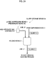
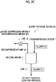
- Figs. 2A to 2C are schematic explanatory views illustrating the structure of the slurry storage device according to the first embodiment of the present invention.
- the slurry storage device 2A is provided with holding means 3 for holding the slurry S and a pH value rise suppressing means 4 for suppressing a rise in the pH value of the slurry S.
- the slurry storage device 2A of the present embodiment is for containing and storing the slurry S prepared by the dispersion device 1. When the storage period is over, the slurry S is transferred to the next process (coating process) via the line L7 provided in the holding means 3.
- the holding means 3 has a space for holding the slurry S, and preferably has a sealable structure having chemical resistance and pressure resistance.
- the specific structure of the holding means 3 is not particularly limited.
- Examples of the holding means 3 include a bottomed tubular structure or a tubular structure having a lid portion that can be sealed and having chemical resistance and pressure resistance.
- the holding means 3 may be provided with various incidental mechanisms.
- a stirring mechanism may be provided in the holding means 3 so that the slurry S can be stirred.
- the contact efficiency between the gas (particularly carbon dioxide (carbon dioxide gas)) supplied by the pH value rise suppressing means 4 described later and the slurry S can be increased, and the pH value rise suppressing effect due to the neutralization reaction or the like can be enhanced.
- a temperature control mechanism may be provided in the holding means 3 to control the temperature suitable for storing the slurry S.
- a temperature control mechanism for example, a heating mechanism may be provided.
- the pH value rise suppressing means 4 is for suppressing the rise in the pH value of the slurry S and suppressing the alkalization of the slurry S.
- the pH value rise suppressing means 4 is not particularly limited as long as means can suppress the alkalization of the slurry S. However, when a pH value regulating agent is added as the pH value rise suppressing means 4, the physical properties and composition of the slurry S may be affected. Therefore, as the pH value rise suppressing means 4, it is preferable to use a means other than adding the pH value regulating agent.
- the pH value of the slurry S is preferably 11 or less, more preferably 10 or less, by the pH value rise suppressing means 4.
- examples of the pH value rise suppressing means 4 of the present embodiment include those provided with a pressurizing means 4A using supply of the pressurized gas.
- the pressurizing means 4A may be any device as long as means can supply a pressurized gas and increase the pressure in the holding means 3 via the line L8, and the specific configuration is not particularly limited.
- gas may be supplied directly into the holding means 3 from a high-pressure gas container (cylinder) 41 or the like, or a pressure pump may be provided to supply gas into the holding means 3.
- the slurry S in the holding means 3 is alkalized by coming into contact with the moisture in the outside air. Therefore, by supplying the pressurized gas by the pressurizing means 4A and making the inside of the holding means 3 positive pressure, it is possible to suppress the inflow of outside air into the holding means 3. As a result, the slurry S in the holding means 3 does not react with the moisture in the outside air, and the rise in the pH value of the slurry S can be suppressed.
- the value of the pressure in the holding means 3 boosted by the pressurizing means 4A is not particularly limited, and can be appropriately set according to the expression conditions of the desired effect, the aspect of use, and the like.
- the lower limit of the pressure value is preferably 0.05 MPa (gauge pressure, the same applies hereinafter) or more, and more preferably 0.1 MPa or more.
- the upper limit of the pressure value is preferably 0.6 MPa or less, and more preferably 0.5 MPa or less.
- Examples of the pressurized gas supplied by the pressurizing means 4A include an inert gas such as nitrogen gas and argon gas, and a gas showing acidity when dissolved in water such as carbon dioxide (carbon dioxide gas).
- an inert gas such as nitrogen gas and argon gas
- a gas showing acidity when dissolved in water such as carbon dioxide (carbon dioxide gas).
- the pressurizing means 4A of the present embodiment it is preferable to use carbon dioxide (carbon dioxide gas) as the pressurized gas.
- carbon dioxide carbon dioxide gas
- the solvent W of the slurry S is water
- carbon dioxide (carbonic dioxide gas) dissolves in water on the surface of the slurry S contained in the holding means 3 to generate an acid component (carbonic acid) . Therefore, on the surface of the slurry S contained in the holding means 3, a neutralization reaction between the alkaline component such as lithium hydroxide and the acid component (carbonic acid) in the slurry S occurs. As a result, it is possible to more reliably suppress the alkalization of the slurry S.
- carbon dioxide carbon dioxide gas
- examples of another aspect of the pH value rise suppressing means 4 of the present embodiment include those provided with a dry air supply means 4B for supplying dry air.
- the dry air supply means 4B is not particularly limited as long as means can supply air (dry air) having a low moisture content (humidity) into the holding means 3.
- a dry air generator 42 capable of generating air from which the moisture is removed may be used.
- the specific configuration of the dry air generator 42 is not particularly limited, and a known generator may be used.
- the dry air supply means 4B as the pH value rise suppressing means 4
- the moisture in the gas in the holding means 3 can be reduced.
- the reaction between the slurry S and the moisture in the gas in the holding means 3 can be suppressed, and the rise in the pH value of the slurry S can be suppressed.
- the dry air does not need to be supplied in a pressurized state, but the pressurized dry air may be supplied. As a result, the effect related to the pressurizing means 4A can also be obtained.
- examples of another aspect of the pH value rise suppressing means 4 of the present embodiment include those provided with a decompression means 4C.
- the decompression means 4C is not particularly limited as long as means can reduce the pressure in the holding means 3.
- Examples of the decompression means 4C include providing a decompression pump 43 for the holding means 3.
- the value of the pressure in the holding means 3 decompressed by the decompression means 4C is not particularly limited, and can be appropriately set according to the expression conditions of the desired effect, the aspect of use, and the like.
- the pressure value is preferably - 0.07 MPa or less.
- the pressure in the holding means 3 is a negative pressure, so that it is possible to reduce the moisture in the gas in the holding means 3.
- the reaction between the slurry S and the moisture in the gas in the holding means 3 can be suppressed, and the rise in the pH value of the slurry S can be suppressed.
- the holding means 3 in the slurry storage device 2A of the present embodiment is not limited to the one provided independently of the dispersion device 1 as illustrated in Figs. 1 and 2A to 2C .
- the configuration (stirring tank 11) in the dispersion device 1 may also have the function of the holding means 3.
- Fig. 3 is a schematic explanatory view illustrating the stirring tank 11 in the dispersion device 1 also having the function of the holding means 3, as another aspect of the slurry production system 100 and the slurry storage device 2A.
- Fig. 3 illustrates the stirring tank 11 provided with the pressurizing means 4A as the pH value rise suppressing means 4, but any of the above-described pH value rise suppressing means 4 may be applied, and is not particularly limited.
- an on/off switching valve 11c is provided on the line L2 connected to the stirring tank 11 of the dispersion device 1, and when the slurry S is prepared, the on/off switching valve 11c is opened to form a circulation path between the stirring tank 11 and the dispersion unit 13.
- the on/off switching valve 11c is closed so that the slurry S can be contained in the stirring tank 11 and the function of the holding means 3 can be provided. Therefore, while the on/off switching valve 11c is closed, carbon dioxide (carbon dioxide gas) is supplied into the stirring tank 11 as a pressurized gas by the pH value rise suppressing means 4 (pressurizing means 4A).
- a part of the line L2 or the line L5 connected to the stirring tank 11 may be branched, and when the storage period ends, the slurry S may be transferred to the next process (coating process) via the branched line L2 or the line L5.
- the configuration of the entire slurry production system 100 can be made compact.
- the implementation conditions of the example are as follows.
- a sealable withstanding pressure container having a volume of 300 mL was used.
- the slurry S 100 mL of an aqueous high nickel slurry containing a positive electrode active material of the composition formula LiNi 0.8 Co 0.15 Al 0.05 was contained in the holding means 3.
- the pressurizing means 4A was used to supply carbon dioxide (carbon dioxide gas) to the holding means 3 (withstanding pressure container), and the pressure in the holding means 3 (withstanding pressure container) was set to 0.1 MPa in gauge pressure.
- the implementation conditions of the comparative example were those using the same holding means 3 and the slurry S as those in the example.
- the comparative example is not provided with the pH value rise suppressing means 4.
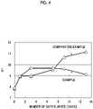
- Fig. 4 is a graph illustrating a time-dependent change in pH values when an aqueous slurry containing a high nickel material is stored using the slurry storage device 2A of the present embodiment.
- the vertical axis of Fig. 4 illustrates the pH value of the slurry S
- the horizontal axis of Fig. 4 illustrates the number of days elapsed since the slurry S was contained in the holding means 3.
- a white square ( ⁇ ) illustrates the example
- a white triangle ( ⁇ ) illustrates the comparative example.
- the pH value increases by approximately 1.5 with the passage of time, but it is found that the pH value does not exceed 10 thereafter, and the pH value remains in the range of 9 to 10. On the other hand, in the comparative example, it is found that the pH value continues to rise with the passage of time.
- the slurry storage device 2A in the present embodiment can suppress the rise in the pH value during storage of the aqueous slurry containing the high nickel material, and keep stable storage.
- the slurry storage device and the slurry storage method of the present embodiment it is possible to suppress alkalization due to a time-dependent change and suppress deterioration of the physical properties of the slurry, particularly for the aqueous slurry containing the high nickel material among the aqueous slurries. As a result, it is possible to appropriately store the aqueous slurry containing the high nickel material.
- the prepared slurry can be appropriately stored, so that the slurry can be transferred to the next process (coating process) while maintaining the quality of the slurry.
- the aqueous slurry containing the high nickel material it is possible to reduce the environmental load and the production cost in the entire production of the lithium ion secondary battery.
- Fig. 5 is an outline illustrating a configuration of a slurry storage device according to a second embodiment of the present invention.
- a slurry storage device 2B of the second embodiment is provided with a pressure sensor 5 and a pressure regulating means 6 for regulating the pressure in the holding means 3 based on the value of the pressure sensor 5 in the holding means 3 in the slurry storage device 2A of the first embodiment.
- Fig. 5 illustrates the device provided with the pressure sensor 5 and the pressure regulating means 6 with respect to the slurry storage device 2A described with reference to Fig. 2A in the first embodiment.
- the description of the same configuration as that of the first embodiment will be omitted.
- the slurry storage device 2B of the present embodiment detects the pressure in the holding means 3 by the pressure sensor 5, and regulates the pressure in the holding means 3 by the pressure regulating means 6 based on a detected value.
- the pressure sensor 5 can detect a state deviating from the pressure value suitable for suppressing the alkalization of the slurry S.
- the pressure can be regulated by the pressure regulating means 6 so that the pressure inside the holding means 3 is an appropriate pressure value. Therefore, it is possible to quickly determine and respond to the maintenance and management related to the storage of the slurry S.
- by connecting the pressure sensor 5 and the pressure regulating means 6 so that data can be input and controlled, it is possible to automate the maintenance and management related to the storage of the slurry S.
- the pressure sensor 5 is not particularly limited as long as a sensor can detect the pressure in the holding means 3.
- a detection result of the pressure sensor 5 may be directly input to the pressure regulating means 6 as detection data, or the detection result recorded by the worker may be manually input to the pressure regulating means 6.
- the detection result of the pressure sensor 5 can be directly input to the pressure regulating means 6 as data.
- the pressure regulating means 6 is not particularly limited as long as means can regulate the pressure in the holding means 3 based on the detection result of the pressure sensor 5.
- Examples of the pressure regulating means 6 include regulating the supply amount of the pressurized gas to the pressurizing means 4A provided as the pH value rise suppressing means 4, regulating the driving force of the decompression pump to the decompression means 4C, and the like.
- a valve 61 which is a mechanism capable of controlling the amount of gas supplied from the high-pressure gas container 41, may be provided.
- valve 61 and the pressure sensor 5 may be connected to each other in a controllable manner, and a control unit (not illustrated) may be provided in which the detection result of the pressure sensor 5 is input, it is determined whether or not the detection result is within an appropriate range, and the opening degree of the valve 61 is determined and operated according to the detection result. As a result, it is possible to automate the maintenance and management related to storage of the slurry.
- a mechanism for regulating the pressure in the holding means 3 is independently provided separately from the pH value rise suppressing means 4. As a result, even in a case where a problem occurs on the pH value rise suppressing means 4 side, the pressure in the holding means 3 can be appropriately maintained, and the slurry S can be stably stored.
- the slurry storage device 2B of the present embodiment is provided with a pressure sensor for detecting the pressure in the holding means and a pressure regulating means for regulating the pressure in the holding means according to the value of the pressure. Therefore, it is possible to quickly respond to the maintenance and management related to storage of the slurry, and more reliably perform stable storage of the aqueous slurry containing the high nickel material. In addition, it also has the effect of being able to automate the maintenance and management itself related to the storage of the slurry.
- the slurry storage device 2B of the present embodiment can also be suitably used as a slurry storage device in the slurry production system 100 illustrated in the first embodiment.
- the slurry storage device 2B of the present embodiment can also be suitably used as a slurry storage device in the slurry production system 100 illustrated in the first embodiment.
- it is possible to quickly respond to the maintenance and management related to the storage of the slurry, and to make the slurry production system capable of more reliably performing stable storage of the aqueous slurry containing the high nickel material.
- it also has the effect of enabling a slurry production system to be automate the maintenance and management itself related to the storage of the slurry.
- the above-described embodiment illustrates an example of the slurry storage device, the slurry production system, and the slurry storage method.
- the slurry storage device, the slurry production system, and the slurry storage method according to the present invention are not limited to the above-described embodiment.
- the slurry storage device, the slurry production system, and the slurry storage method according to the above-described embodiment may be modified without changing the concept described in the aspects.
- an adsorbent that adsorbs moisture may be provided in the holding means.
- the high-pressure gas container may also be connected to the dispersion unit and used as a means for supplying carbon dioxide (carbon dioxide gas) during the dispersion treatment.
- a high-pressure gas container may be connected so that the holding means and the dispersion unit can be switched.
- the slurry storage device and the slurry storage method of the present invention can be used as a storage technique capable of appropriately storing the slurry.
- these device and method can be suitably used as a storage technique for appropriately storing an aqueous slurry containing a high nickel material.
- the slurry production system of the present invention can be used as a slurry production system that can be stored in a state where the quality of the slurry is maintained after the slurry is prepared.
- the system can be suitably used as a slurry production system for preparing an aqueous slurry containing a high nickel material.
Landscapes
- Chemical & Material Sciences (AREA)
- Chemical Kinetics & Catalysis (AREA)
- Engineering & Computer Science (AREA)
- General Chemical & Material Sciences (AREA)
- Electrochemistry (AREA)
- Mechanical Engineering (AREA)
- Dispersion Chemistry (AREA)
- Materials Engineering (AREA)
- Manufacturing & Machinery (AREA)
- Inorganic Chemistry (AREA)
- Organic Chemistry (AREA)
- Battery Electrode And Active Subsutance (AREA)
- Accessories For Mixers (AREA)
Abstract
Description
- The present invention relates to a slurry storage device, a slurry production system, and a slurry storage method. More specifically, the present invention relates to the slurry storage device, the slurry production system, and the slurry storage method for an aqueous slurry containing a high nickel material.
- With a widespread use of portable electronic devices such as notebook computers and tablet terminals, a demand for secondary batteries is increasing. As such a secondary battery, a lithium ion secondary battery having a high energy density, a high operating voltage, and being capable of downsizing and weight saving is widely used.
- Normally, the lithium ion secondary battery is a secondary battery (storage battery) that uses lithium ion as an ion responsible for electrical conduction, and means a power storage device called, for example, a lithium ion battery, a lithium secondary battery, a lithium all-solid-state battery, a lithium polymer battery, a lithium gel battery, or the like.
- As a positive electrode active material used in such a lithium ion secondary battery, as described in
NPL 1, a lithium transition metal composite oxide containing a transition metal such as nickel, cobalt, and manganese is known. - Among the lithium transition metal composite oxides, a material having a particularly high nickel content is called a high nickel material, and is attracting attention as a positive electrode active material capable of stably extracting a high electric capacity.
- On the other hand, in the production of electrodes for secondary batteries, although a slurry of a positive electrode active material (muddy suspension or paste suspended in a liquid using a solid as a solvent or a dispersion medium) is applied to a surface of a current collector, an organic solvent is mainly used when the slurry is produced. However, in recent years, regulations on the use of organic solvents (emission regulations) have become stricter in terms of environmental load, and the cost of a treatment to clear the emission regulations tends to increase. Therefore, it is required to reduce the use of organic solvents from the viewpoint of reducing the environmental load and the manufacturing cost.
- For example,
PTL 1 describes an aqueous slurry in which an aqueous solution containing a specific binder component and an electrochemically activating compound (containing a positive electrode active material) are mixed as a slurry for producing an electrode. - [PTL 1]
Japanese Unexamined Patent Publication No. 2013-38074 - [NPL 1] Takashi Mukai, "High Energy Density and High Output of Electrode Materials for Next-Generation Batteries", Technical Information Association, Inc., November 30, 2017,
- In the production of electrodes for secondary batteries, it may not be possible to perform a coating process immediately after preparing a slurry due to circumstances such as a production schedule. In this case, the prepared slurry may be temporarily stored and then subjected to the coating process.
- On the other hand, among the aqueous slurries (pastes using water as a solvent or a dispersion medium), the present inventors have found that, in particular, when storing an aqueous slurry containing a high nickel material, the pH value of the slurry rises with the passage of time, and the physical properties of the slurry deteriorate. When the pH value of the slurry rises, there is a problem that the current collector coated with the slurry is corroded in the coating process, which is a next process . In addition, there is a problem that the coating itself on the current collector is difficult due to the deterioration of the physical properties of the slurry.
- It was considered that the main component (positive electrode active material) of the slurry and water were sufficiently mixed in the aqueous slurry at the time of preparing the slurry, but according to the findings obtained by the present inventors, it was clarified that the prepared aqueous slurry was alkalized with the passage of time. Therefore, it is necessary to store the aqueous slurry as described in
PTL 1 under appropriate conditions. - An object of the present invention is to provide a slurry storage device, a slurry production system, and a slurry storage method capable of appropriately storing an aqueous slurry containing a particularly high nickel material among aqueous slurries.
- As a result of diligent studies on the above-described problems, the present inventors have completed the present invention by finding that aqueous slurry particularly containing a high nickel material among the aqueous slurries can be appropriately stored by providing pH value rise suppressing means for suppressing a rise in the pH value of the slurry with respect to holding means for holding the slurry.
- That is, the present invention is a slurry storage device, a slurry production system, and a slurry storage method as follows.
- According to an aspect of the present invention for solving the above problems, there is provided a slurry storage device that stores an aqueous slurry containing a high nickel material prepared by a dispersion device which mixes a powder and a solvent, the device including a holding means that holds the aqueous slurry containing the high nickel material, and a pH value rise suppressing means that suppresses a rise in a pH value of the aqueous slurry containing the high nickel material.
- According to the slurry storage device of the present invention, by providing the pH value rise suppressing means that suppresses the rise in the pH value of the aqueous slurry containing the high nickel material, it is possible to suppress alkalization (pH value rise) of the aqueous slurry containing the high nickel material held in the holding means due to a time-dependent change and suppress deterioration of the physical properties of the slurry. As a result, it is possible to stably store the aqueous slurry containing the high nickel material for a long period of time.
- In addition, in one embodiment of the slurry storage device of the present invention, the pH value rise suppressing means includes a pressurizing means using supply of a pressurized gas.
- Based on the findings of the present inventors, it is estimated that the slurry in the holding means is alkalized by coming into contact with the moisture in the outside air. On the other hand, according to this feature, it is possible to suppress the inflow of outside air into the holding means. As a result, the slurry in the holding means does not react with the moisture in the outside air, the rise in the pH value of the slurry can be easily suppressed, and the stable storage of the aqueous slurry containing the high nickel material can be easily performed.
- In addition, in one embodiment of the slurry storage device of the present invention, the pressurized gas supplied by the pressurizing means is a gas containing carbon dioxide (carbon dioxide gas).
- According to this feature, in addition to suppressing the inflow of outside air into the holding means, a neutralization reaction (2LiOH + CO2 → Li2CO3 + H2O) occurs between the acid component generated by dissolving carbon dioxide (carbon dioxide gas, CO2) in water and the alkaline component in the slurry on the surface of the slurry contained in the holding means. As a result, it is possible to more reliably suppress the strong alkalization of the slurry (phenomenon in which the pH value exceeds 10).
- In addition, in one embodiment of the slurry storage device of the present invention, the pH value rise suppressing means includes a dry air supply means that supplies dry air.
- According to this feature, it is possible to reduce the moisture in the gas in the holding means. As a result, the reaction between the slurry and the moisture in the gas in the holding means can be suppressed, the rise in the pH value of the slurry can be easily suppressed, and the stable storage of the aqueous slurry containing the high nickel material can be easily performed.
- In addition, in one embodiment of the slurry storage device of the present invention, the pH value rise suppressing means includes a decompression means.
- According to this feature, the gas component in the holding means can be removed by reducing the pressure in the holding means. In addition, by removing the gas component, it is possible to reduce the moisture in the gas in the holding means. As a result, the reaction between the slurry and the moisture in the holding means can be suppressed, the rise in the pH value of the slurry can be easily suppressed, and the stable storage of the aqueous slurry containing the high nickel material can be easily performed.
- By using a vacuum pump or the like as the decompression means to create a vacuum state inside the holding means, it is possible to further suppress the rise in the pH value.
- In addition, in one embodiment of the slurry storage device of the present invention, a pressure sensor is provided in the holding means, and the slurry storage device further includes a pressure regulating means that regulates a pressure in the holding means based on a value of the pressure sensor.
- According to this feature, by providing a means for detecting the pressure in the holding means and a means for regulating the pressure according to the value, it is possible to quickly respond to the maintenance and management related to storage of the slurry, and more reliably perform stable storage of the aqueous slurry containing the high nickel material.
- In addition, it also has the effect of being able to automate the maintenance and management itself related to the storage of the slurry.
- According to an aspect of the present invention for solving the above problems, there is provided a slurry production system including the above-described slurry storage device; and a dispersion device that prepares an aqueous slurry containing a high nickel material.
- According to the slurry production system, the slurry prepared by the dispersion device can be stably stored in a state where alkalization and deterioration of physical properties of the slurry are suppressed until the slurry is transferred to the next process (coating process) . As a result, it is possible to facilitate the storage and handling of the aqueous slurry containing the high nickel material, and to reduce the environmental load and the production cost in the entire production of the lithium ion secondary battery.
- According to an aspect of the present invention for solving the above problems, there is provided a slurry storage method of storing an aqueous slurry containing a high nickel material prepared by a dispersion device which mixes a powder and a solvent, the method including a holding step of holding the aqueous slurry containing the high nickel material, and a pH value rise suppressing step of suppressing a rise in a pH value of the aqueous slurry containing the high nickel material.
- According to the slurry storage method, by the pH value rise suppressing step of suppressing the rise in the pH value of the aqueous slurry containing the high nickel material, it is possible to suppress alkalization of the aqueous slurry containing the high nickel material held by the holding step due to a time-dependent change and suppress deterioration of the physical properties of the slurry. As a result, it is possible to stably store the aqueous slurry containing the high nickel material for a long period of time.
- According to the present invention, it is possible to provide a slurry storage device, a slurry production system, and a slurry storage method capable of appropriately storing an aqueous slurry containing a particularly high nickel material among the aqueous slurries.
-
-
Fig. 1 is a schematic explanatory view illustrating a structure of a slurry production system according to an first embodiment of the present invention. -
Fig. 2A is a schematic explanatory view illustrating a structure of a slurry storage device according to the first embodiment of the present invention. -
Fig. 2B is a schematic explanatory view illustrating another aspect of the slurry storage device according to the first embodiment of the present invention. -
Fig. 2C is a schematic explanatory view illustrating another aspect of the slurry storage device according to the first embodiment of the present invention. -
Fig. 3 is a schematic explanatory view illustrating another aspect of the slurry production system and the slurry storage device according to the first embodiment of the present invention. -
Fig. 4 is a graph illustrating a time-dependent change in pH values when an aqueous slurry containing a high nickel material is stored using the slurry storage device according to the first embodiment of the present invention. -
Fig. 5 is a schematic explanatory view illustrating a structure of a slurry storage device according to a second embodiment of the present invention. - Hereinafter, a slurry storage device, a slurry production system, and a slurry storage method according to the present invention will be described in detail with reference to the drawings.
- The slurry storage device and the slurry production system described in the embodiment are merely exemplified for describing the slurry storage device and the slurry production system according to the present invention, and the present invention is not limited thereto. The slurry storage method of the present invention is replaced with the following description of a structure and operation of the slurry storage device.
- Slurry S to be stored in the present invention is an aqueous slurry containing a lithium transition metal composite oxide used as a positive electrode active material for a lithium ion secondary battery. Examples thereof include an aqueous slurry containing a so-called high nickel material having a particularly high nickel content in a transition metal composite oxide containing lithium.
- In the present invention, the high nickel material means a layered oxide-based material containing lithium in which Ni exceeds 0.5 in a case where the transition metal element in the positive electrode active material is 1. Normally, a positive electrode active material having Ni of less than 0.5 is produced by firing in air using lithium carbonate, a transition metal hydroxide or the like as raw materials. Therefore, the positive electrode active material contains substantially no lithium hydroxide having high reactivity. On the other hand, a positive electrode active material with Ni of 0.5 or more is produced by firing in oxygen using highly reactive lithium hydroxide, transition metal hydroxides, transition metal oxyhydroxides or the like as raw materials. Therefore, the positive electrode active material contains a large amount of highly reactive lithium hydroxide. In addition, a positive electrode active material having Ni of 0.5 or more is likely to generate lithium hydroxide by a proton exchange reaction. Therefore, it is considered that such a high nickel material is likely to be alkalized with the passage of time during storage in a case where the high nickel material is prepared as an aqueous slurry using water as a solvent or a dispersion medium.
- Examples of the high nickel material include LiNiO2, Li(Ni0.6Co0.4)O2, Li(Ni0.8Co0.2)O2, Li(Ni0.8Co0.15Al0.05)O2, Li(Ni0.6Co0.2Mn0.2)O2, Li(Ni0.8Co0.1Mn0.1)O2, Li(Ni0.9Co0.05Mn0.05)O2, and the like.
- Other atoms may be replaced for a part of the atomic sites constituting the high nickel material.
- Examples thereof include a material in which another alkali metal atom replaces a part of the lithium atom site, a material in which a fluorine atom replaces a part of the oxygen atom site of a high nickel material, a material in which an aluminum atom replaces a part of the transition metal atom sites of a high nickel material, and the like.
- That is, examples of the high nickel material in the present invention include those represented by LiaAbNicMdAleOfFg (meaning 0 < a ≤ 1, 0 ≤ b < 1, 0.5 ≤ c ≤ 1, 0 ≤ d ≤ 0.5, 0 ≤ e ≤ 0.5, 1 < f ≤ 2, 0 ≤ g < 1, a + b = 1, c + d + e = 1, f + g = 2, A = Na, K, Rb, M = Co, Mn, Fe, Ti, Zr, Nb, Mo, W) in the composition formula.
-
Fig. 1 is a schematic explanatory view illustrating a structure of a slurry production system according to the first embodiment of the present invention. - As illustrated in
Fig. 1 , aslurry production system 100 is provided with adispersion device 1 and aslurry storage device 2A. - In the
slurry production system 100 of the present embodiment, the slurry S is first prepared in thedispersion device 1, and then the prepared slurry S is stored in theslurry storage device 2A. Thereafter, the stored slurry S is transferred from theslurry storage device 2A to a place where the next process is performed according to the timing when the next process (mainly the coating process) is performed. - The
dispersion device 1 may be any device as long as a device can prepare an aqueous slurry containing a high nickel material as the slurry S, and the details of the device configuration are not particularly limited. Thedispersion device 1 in the present embodiment refers to a device capable of mixing at least a solid (powder) and a liquid (solvent) to prepare a slurry which is a mixture of a granular solid matter and a liquid, and also includes a device called a mixing device, a kneading device, and the like. As will be described later, it is more preferable that thedispersion device 1 in the present embodiment has a configuration capable of mixing a gas as well. As a result, it is possible to suppress the alkalization of the slurry S at the time of preparation. - Examples of the raw material of the slurry S to be charged into the
dispersion device 1 include powder of a positive electrode active material used in a lithium ion secondary battery (hereinafter, simply referred to as a "powder P"), solvent W (water), a binder, a conductive material, and the like. Here, as the positive electrode active material, it is preferable to use a lithium transition metal composite oxide known as a high nickel material. In addition, the binder, the conductive material and the like are appropriately used as needed, and the specific substance is not particularly limited. A known substance can be used in the preparation of the aqueous slurry. - In addition, when preparing the slurry S, a gas such as carbon dioxide (carbon dioxide gas) or an inert gas may be supplied to the
dispersion device 1. In particular, it is preferable to supply a gas containing carbon dioxide (carbon dioxide gas) to thedispersion device 1. More preferably, it is preferable to supply only carbon dioxide (carbon dioxide gas) to thedispersion device 1. As a result, it is possible to neutralize lithium hydroxide generated during the preparation of the aqueous slurry containing the high nickel material and suppress the strong alkalization of the aqueous slurry containing the high nickel material during the preparation. - In a case where the high nickel material is not contained, lithium hydroxide is not contained in the slurry. Therefore, by supplying carbon dioxide (carbon dioxide gas), the pH value of the aqueous slurry is low (pH value is less than 5), and the transition metal may be dissolved with acid. In the slurry in which the transition metal is dissolved in this manner, the metal may re-precipitate during charging and discharging. In addition, it is not preferable because the discharge capacity of the positive electrode active material is small and stable cycle characteristics cannot be obtained.
- The pH value is an index indicating the hydrogen ion concentration. That is, in a case where the pH value is less than 7, it is acidic, and in a case where the pH value exceeds 7, it is alkaline. In the present application, the pH value is a value measured by a pH meter, but as another method, the pH value may be determined by an indicator method or the like.
-
Fig. 1 illustrates thedispersion device 1 including apowder supply unit 10, a stirringtank 11, a circulationliquid feed pump 12, and adispersion unit 13. Thedispersion device 1 illustrated inFig. 1 illustrates an example of thedispersion device 1 in the present embodiment, and is not limited to the configuration illustrated inFig. 1 . - The
powder supply unit 10 charges a solid component (powder P) of the raw materials of the slurry S into thedispersion unit 13. - As for a structure of the
powder supply unit 10, a known structure can be used in the dispersion device for charging the solid component, and the structure is not particularly limited. For example, as illustrated inFig. 1 , as an example of thepowder supply unit 10, ahopper 10a having an upper opening portion and a lower opening portion may be provided and installed so that the powder P is charged from the upper opening portion and is supplied from the lower opening portion to thedispersion unit 13 via a line L1. - In addition, various incidental mechanisms may be provided on the
powder supply unit 10 and the line L1. Examples of such an incidental mechanism include a stirring mechanism for stirring the powder P in thepowder supply unit 10, a quantitative supply mechanism for quantitatively supplying the powder P from thepowder supply unit 10 to thedispersion unit 13, a vibrator or a kicker for removing the powder P adhering to thepowder supply unit 10, and the like. - The stirring
tank 11 supplies the liquid component (solvent W) of the raw materials of the slurry S to thedispersion unit 13. In addition, the stirringtank 11 is connected to thedispersion unit 13 in a circulatable manner and stores the prepared slurry S. As a structure of the stirringtank 11, a known structure for supplying the liquid component and storing the slurry in the dispersion device can be used, and is not particularly limited. For example, as illustrated inFig. 1 , as an example of the stirringtank 11, a tankmain body 11a and astirring device 11b inside the tankmain body 11a are provided and are connected to thedispersion unit 13 in a circulatable manner via a line L2 and a line L3. In addition, the tankmain body 11a may be provided with a line L4 for supplying the solvent W (water) from the outside and a line L5 for exhausting the contents (solvent W or slurry S) in the tankmain body 11a to the outside of the system. - The stirring
tank 11 can be used also as holding means 3 of theslurry storage device 2A. A description of common use of the holding means 3 of theslurry storage device 2A and the stirringtank 11 will be described later. - The circulation
liquid feed pump 12 is for controlling the flow directions of the solvent W and the slurry S in thedispersion device 1 and regulating the flow rate. - For example, as illustrated in
Fig. 1 , as the circulationliquid feed pump 12, a pump capable of sucking the solvent W and the slurry S in the stirringtank 11 and delivering the solvent W and the slurry S toward thedispersion unit 13 may be provided on the line L2. As a result, the solvent W and the slurry S circulate between the stirringtank 11 and thedispersion unit 13, and the dispersion treatment in thedispersion unit 13 can be repeated, so that it is possible to homogenize the dispersion of the powder P with respect to the solvent W. - The
dispersion unit 13 is for preparing a slurry S by mixing and dispersing a solid component (powder P) and a liquid component (solvent W). - For example, as the
dispersion unit 13, one having a configuration that disperses by ultrasonic waves, one having a configuration that disperses by shearing force, such as a planetary mixer and a twin-screw kneader, one having a configuration that disperses by cavitation and shearing force, and the like may be used. From the viewpoint that a kneading process is not required and excessive pulverization of the positive electrode active material is unlikely to occur, it is more preferable to use one having a configuration in which dispersion is performed by cavitation and shearing force. Examples of those that disperse by cavitation and shearing force include "JET PASTER (registered trademark)" manufactured by Nihon Spindle Manufacturing Co., Ltd. as a commercially available product. - The powder P and the solvent W are supplied to the
dispersion unit 13 from thepowder supply unit 10 and the stirringtank 11 via the lines L1 and L2. - Means for supplying a binder, a conductive material, or the like to the
dispersion unit 13 is not particularly limited. For example, it may be supplied together with the powder P from thepowder supply unit 10 via the line L1, or supplied to the stirringtank 11 and mixed with the solvent W and then supplied via the line L2. - The slurry S prepared in the
dispersion unit 13 may be circulated to the stirringtank 11 via the line L3, or may be supplied to theslurry storage device 2A via the line L6. In addition, the slurry S in the stirringtank 11 may also be circulated to thedispersion unit 13 via the line L2, or may be supplied to theslurry storage device 2A by branching a part of the line L2 or the line L5. - After the preparation of the slurry S, the determination regarding a supply destination of the slurry S, such as circulation in the
dispersion device 1 or supply to theslurry storage device 2A, can be appropriately performed according to the preparation amount and preparation conditions of the slurry S. For example, the supply destination of the slurry S may be determined based on the driving time of thedispersion unit 13, the input amount of the powder P, and the like. In addition, the determination regarding the supply destination of the slurry S and the switching of the supply destination based on the determination may be performed manually by a worker, and may be executed by a control unit including a CPU or a circuit for executing the program. -
Figs. 2A to 2C are schematic explanatory views illustrating the structure of the slurry storage device according to the first embodiment of the present invention. - As illustrated in
Figs. 2A to 2C , theslurry storage device 2A is provided with holding means 3 for holding the slurry S and a pH value rise suppressingmeans 4 for suppressing a rise in the pH value of the slurry S. - The
slurry storage device 2A of the present embodiment is for containing and storing the slurry S prepared by thedispersion device 1. When the storage period is over, the slurry S is transferred to the next process (coating process) via the line L7 provided in the holding means 3. - The holding means 3 has a space for holding the slurry S, and preferably has a sealable structure having chemical resistance and pressure resistance.
- The specific structure of the holding means 3 is not particularly limited. Examples of the holding means 3 include a bottomed tubular structure or a tubular structure having a lid portion that can be sealed and having chemical resistance and pressure resistance.
- In addition, the holding means 3 may be provided with various incidental mechanisms. For example, a stirring mechanism may be provided in the holding means 3 so that the slurry S can be stirred. As a result, the contact efficiency between the gas (particularly carbon dioxide (carbon dioxide gas)) supplied by the pH value rise suppressing
means 4 described later and the slurry S can be increased, and the pH value rise suppressing effect due to the neutralization reaction or the like can be enhanced. In addition, as another example, a temperature control mechanism may be provided in the holding means 3 to control the temperature suitable for storing the slurry S. As such a temperature control mechanism, for example, a heating mechanism may be provided. As a result, it is possible to discharge the gas (carbon dioxide (carbon dioxide gas)) dissolved in the slurry S and impart a function of suppressing alkalization on the surface of the slurry S. In addition, as another example, a cooling mechanism may be provided. As a result, it is possible to impart a function of maintaining the gas (carbon dioxide (carbon dioxide gas)) supplied in the holding means 3 at a lower pressure. Furthermore, as the temperature control mechanism, a mechanism capable of switching between heating and cooling may be provided, and the above-described functions may be appropriately selected to perform executable control. As a result, in combination with the pH value rise suppressingmeans 4 described later, it is possible to further suppress the rise in the pH value of the slurry S during storage and keep stable storage. - The pH value rise suppressing
means 4 is for suppressing the rise in the pH value of the slurry S and suppressing the alkalization of the slurry S. - The pH value rise suppressing
means 4 is not particularly limited as long as means can suppress the alkalization of the slurry S. However, when a pH value regulating agent is added as the pH value rise suppressingmeans 4, the physical properties and composition of the slurry S may be affected. Therefore, as the pH value rise suppressingmeans 4, it is preferable to use a means other than adding the pH value regulating agent. - Normally, it is known that when the pH value of the slurry S exceeds 11, there is a problem that a current collector (mainly an aluminum current collector) is corroded at the time of coating.
- Therefore, the pH value of the slurry S is preferably 11 or less, more preferably 10 or less, by the pH value rise suppressing
means 4. - As illustrated in
Fig. 2A , examples of the pH value rise suppressingmeans 4 of the present embodiment include those provided with a pressurizing means 4A using supply of the pressurized gas. - The pressurizing means 4Amay be any device as long as means can supply a pressurized gas and increase the pressure in the holding means 3 via the line L8, and the specific configuration is not particularly limited. For example, as illustrated in
Fig. 2A , gas may be supplied directly into the holding means 3 from a high-pressure gas container (cylinder) 41 or the like, or a pressure pump may be provided to supply gas into the holding means 3. - As a result of the study by the present inventors, it is estimated that the slurry S in the holding means 3 is alkalized by coming into contact with the moisture in the outside air. Therefore, by supplying the pressurized gas by the pressurizing means 4A and making the inside of the holding means 3 positive pressure, it is possible to suppress the inflow of outside air into the holding means 3. As a result, the slurry S in the holding means 3 does not react with the moisture in the outside air, and the rise in the pH value of the slurry S can be suppressed.
- The value of the pressure in the holding means 3 boosted by the pressurizing means 4A is not particularly limited, and can be appropriately set according to the expression conditions of the desired effect, the aspect of use, and the like. For example, from the viewpoint of surely obtaining the effect of suppressing the alkalization of the slurry S by pressurization, the lower limit of the pressure value is preferably 0.05 MPa (gauge pressure, the same applies hereinafter) or more, and more preferably 0.1 MPa or more. In addition, for example, from the viewpoint of the pressure resistance of the holding means 3, the upper limit of the pressure value is preferably 0.6 MPa or less, and more preferably 0.5 MPa or less.
- Examples of the pressurized gas supplied by the pressurizing means 4A include an inert gas such as nitrogen gas and argon gas, and a gas showing acidity when dissolved in water such as carbon dioxide (carbon dioxide gas).
- In the pressurizing means 4A of the present embodiment, it is preferable to use carbon dioxide (carbon dioxide gas) as the pressurized gas. In this case, since the solvent W of the slurry S is water, carbon dioxide (carbonic dioxide gas) dissolves in water on the surface of the slurry S contained in the holding means 3 to generate an acid component (carbonic acid) . Therefore, on the surface of the slurry S contained in the holding means 3, a neutralization reaction between the alkaline component such as lithium hydroxide and the acid component (carbonic acid) in the slurry S occurs. As a result, it is possible to more reliably suppress the alkalization of the slurry S. In addition, from the viewpoint of not affecting the physical properties and composition of the slurry S, it is preferable to use carbon dioxide (carbon dioxide gas) as the pressurized gas.
- When supplying carbon dioxide (carbon dioxide gas) as a pressurized gas, it is preferable to supply carbon dioxide directly from a high-pressure gas container. The high-pressure gas container for carbon dioxide (carbon dioxide gas) is easily available and does not require a driving device such as a pump to supply the pressurized gas. As a result, it is possible to reduce the cost of storing the slurry S.
- As illustrated in
Fig. 2B , examples of another aspect of the pH value rise suppressingmeans 4 of the present embodiment include those provided with a dry air supply means 4B for supplying dry air. - The dry air supply means 4B is not particularly limited as long as means can supply air (dry air) having a low moisture content (humidity) into the holding means 3. As the dry air supply means 4B, a
dry air generator 42 capable of generating air from which the moisture is removed may be used. The specific configuration of thedry air generator 42 is not particularly limited, and a known generator may be used. As the dry air in the present embodiment, it is preferable to use air having an absolute humidity of 1% or less from the viewpoint of surely obtaining the effect of suppressing the alkalization of the slurry S. - By providing the dry air supply means 4B as the pH value rise suppressing
means 4, the moisture in the gas in the holding means 3 can be reduced. As a result, the reaction between the slurry S and the moisture in the gas in the holding means 3 can be suppressed, and the rise in the pH value of the slurry S can be suppressed. - In the dry air supply means 4B, the dry air does not need to be supplied in a pressurized state, but the pressurized dry air may be supplied. As a result, the effect related to the pressurizing means 4A can also be obtained.
- As illustrated in
Fig. 2C , examples of another aspect of the pH value rise suppressingmeans 4 of the present embodiment include those provided with a decompression means 4C. - The decompression means 4C is not particularly limited as long as means can reduce the pressure in the holding means 3. Examples of the decompression means 4C include providing a
decompression pump 43 for the holding means 3. - The value of the pressure in the holding means 3 decompressed by the decompression means 4C is not particularly limited, and can be appropriately set according to the expression conditions of the desired effect, the aspect of use, and the like. For example, from the viewpoint of surely obtaining the effect of suppressing the alkalization of the slurry S, the pressure value is preferably - 0.07 MPa or less.
- By providing the decompression means 4C as the pH value rise suppressing
means 4, the pressure in the holding means 3 is a negative pressure, so that it is possible to reduce the moisture in the gas in the holding means 3. As a result, the reaction between the slurry S and the moisture in the gas in the holding means 3 can be suppressed, and the rise in the pH value of the slurry S can be suppressed. - In addition, the holding means 3 in the
slurry storage device 2A of the present embodiment is not limited to the one provided independently of thedispersion device 1 as illustrated inFigs. 1 and2A to 2C . For example, the configuration (stirring tank 11) in thedispersion device 1 may also have the function of the holding means 3. -
Fig. 3 is a schematic explanatory view illustrating the stirringtank 11 in thedispersion device 1 also having the function of the holding means 3, as another aspect of theslurry production system 100 and theslurry storage device 2A. -
Fig. 3 illustrates the stirringtank 11 provided with the pressurizing means 4A as the pH value rise suppressingmeans 4, but any of the above-described pH value rise suppressingmeans 4 may be applied, and is not particularly limited. - As illustrated in
Fig. 3 , an on/off switchingvalve 11c is provided on the line L2 connected to the stirringtank 11 of thedispersion device 1, and when the slurry S is prepared, the on/off switchingvalve 11c is opened to form a circulation path between the stirringtank 11 and thedispersion unit 13. On the other hand, when the slurry S is stored, the on/off switchingvalve 11c is closed so that the slurry S can be contained in the stirringtank 11 and the function of the holding means 3 can be provided. Therefore, while the on/off switchingvalve 11c is closed, carbon dioxide (carbon dioxide gas) is supplied into the stirringtank 11 as a pressurized gas by the pH value rise suppressing means 4 (pressurizing means 4A). Therefore, it is possible to suppress alkalization of the slurry S in the stirringtank 11, and keep stable storage. A part of the line L2 or the line L5 connected to the stirringtank 11 may be branched, and when the storage period ends, the slurry S may be transferred to the next process (coating process) via the branched line L2 or the line L5. - As illustrated in
Fig. 3 , by using the stirringtank 11 of thedispersion device 1 also as the holding means 3 of theslurry storage device 2A of the present embodiment, the configuration of the entireslurry production system 100 can be made compact. - Hereinafter, a specific example of the slurry storage device of the present embodiment will be described.
- The implementation conditions of the example are as follows. As the holding means 3, a sealable withstanding pressure container having a volume of 300 mL was used. In addition, as the slurry S, 100 mL of an aqueous high nickel slurry containing a positive electrode active material of the composition formula LiNi0.8Co0.15Al0.05 was contained in the holding means 3. Furthermore, as the pH value rise suppressing
means 4, the pressurizing means 4A was used to supply carbon dioxide (carbon dioxide gas) to the holding means 3 (withstanding pressure container), and the pressure in the holding means 3 (withstanding pressure container) was set to 0.1 MPa in gauge pressure. - On the other hand, the implementation conditions of the comparative example were those using the same holding means 3 and the slurry S as those in the example. In addition, the comparative example is not provided with the pH value rise suppressing
means 4. -
Fig. 4 is a graph illustrating a time-dependent change in pH values when an aqueous slurry containing a high nickel material is stored using theslurry storage device 2A of the present embodiment. The vertical axis ofFig. 4 illustrates the pH value of the slurry S, and the horizontal axis ofFig. 4 illustrates the number of days elapsed since the slurry S was contained in the holding means 3. In addition, here, a white square (◇) illustrates the example, and a white triangle (Δ) illustrates the comparative example. - From
Fig. 4 , in the example, the pH value increases by approximately 1.5 with the passage of time, but it is found that the pH value does not exceed 10 thereafter, and the pH value remains in the range of 9 to 10. On the other hand, in the comparative example, it is found that the pH value continues to rise with the passage of time. - Therefore, it was shown that the
slurry storage device 2A in the present embodiment can suppress the rise in the pH value during storage of the aqueous slurry containing the high nickel material, and keep stable storage. - As described above, according to the slurry storage device and the slurry storage method of the present embodiment, it is possible to suppress alkalization due to a time-dependent change and suppress deterioration of the physical properties of the slurry, particularly for the aqueous slurry containing the high nickel material among the aqueous slurries. As a result, it is possible to appropriately store the aqueous slurry containing the high nickel material.
- In addition, by using the slurry production system of the present embodiment, the prepared slurry can be appropriately stored, so that the slurry can be transferred to the next process (coating process) while maintaining the quality of the slurry. In particular, by facilitating the storage and handling of the aqueous slurry containing the high nickel material, it is possible to reduce the environmental load and the production cost in the entire production of the lithium ion secondary battery.
-
Fig. 5 is an outline illustrating a configuration of a slurry storage device according to a second embodiment of the present invention. - As illustrated in
Fig. 5 , aslurry storage device 2B of the second embodiment is provided with apressure sensor 5 and a pressure regulating means 6 for regulating the pressure in the holding means 3 based on the value of thepressure sensor 5 in the holding means 3 in theslurry storage device 2A of the first embodiment.Fig. 5 illustrates the device provided with thepressure sensor 5 and the pressure regulating means 6 with respect to theslurry storage device 2A described with reference toFig. 2A in the first embodiment. In addition, the description of the same configuration as that of the first embodiment will be omitted. - The
slurry storage device 2B of the present embodiment detects the pressure in the holding means 3 by thepressure sensor 5, and regulates the pressure in the holding means 3 by the pressure regulating means 6 based on a detected value. As a result, in a case where the holding means 3 is pressurized or depressurized by the pH value rise suppressingmeans 4, thepressure sensor 5 can detect a state deviating from the pressure value suitable for suppressing the alkalization of the slurry S. In addition, the pressure can be regulated by the pressure regulating means 6 so that the pressure inside the holding means 3 is an appropriate pressure value. Therefore, it is possible to quickly determine and respond to the maintenance and management related to the storage of the slurry S. In addition, by connecting thepressure sensor 5 and the pressure regulating means 6 so that data can be input and controlled, it is possible to automate the maintenance and management related to the storage of the slurry S. - The
pressure sensor 5 is not particularly limited as long as a sensor can detect the pressure in the holding means 3. A detection result of thepressure sensor 5 may be directly input to the pressure regulating means 6 as detection data, or the detection result recorded by the worker may be manually input to the pressure regulating means 6. In order to automate the maintenance and management related to the storage of the slurry S, it is preferable that the detection result of thepressure sensor 5 can be directly input to the pressure regulating means 6 as data. - The pressure regulating means 6 is not particularly limited as long as means can regulate the pressure in the holding means 3 based on the detection result of the
pressure sensor 5. Examples of the pressure regulating means 6 include regulating the supply amount of the pressurized gas to the pressurizing means 4A provided as the pH value rise suppressingmeans 4, regulating the driving force of the decompression pump to the decompression means 4C, and the like. - More specifically, as illustrated in
Fig. 5 , on the line L9 connecting the high-pressure gas container 41 and the holding means 3, as the pressure regulating means 6, avalve 61, which is a mechanism capable of controlling the amount of gas supplied from the high-pressure gas container 41, may be provided. - In addition, the
valve 61 and thepressure sensor 5 may be connected to each other in a controllable manner, and a control unit (not illustrated) may be provided in which the detection result of thepressure sensor 5 is input, it is determined whether or not the detection result is within an appropriate range, and the opening degree of thevalve 61 is determined and operated according to the detection result. As a result, it is possible to automate the maintenance and management related to storage of the slurry. - Furthermore, as another example of the pressure regulating means 6, a mechanism for regulating the pressure in the holding means 3 is independently provided separately from the pH value rise suppressing
means 4. As a result, even in a case where a problem occurs on the pH value rise suppressingmeans 4 side, the pressure in the holding means 3 can be appropriately maintained, and the slurry S can be stably stored. - As described above, the
slurry storage device 2B of the present embodiment is provided with a pressure sensor for detecting the pressure in the holding means and a pressure regulating means for regulating the pressure in the holding means according to the value of the pressure. Therefore, it is possible to quickly respond to the maintenance and management related to storage of the slurry, and more reliably perform stable storage of the aqueous slurry containing the high nickel material. In addition, it also has the effect of being able to automate the maintenance and management itself related to the storage of the slurry. - In addition, the
slurry storage device 2B of the present embodiment can also be suitably used as a slurry storage device in theslurry production system 100 illustrated in the first embodiment. As a result, it is possible to quickly respond to the maintenance and management related to the storage of the slurry, and to make the slurry production system capable of more reliably performing stable storage of the aqueous slurry containing the high nickel material. In addition, it also has the effect of enabling a slurry production system to be automate the maintenance and management itself related to the storage of the slurry. - The above-described embodiment illustrates an example of the slurry storage device, the slurry production system, and the slurry storage method. The slurry storage device, the slurry production system, and the slurry storage method according to the present invention are not limited to the above-described embodiment. The slurry storage device, the slurry production system, and the slurry storage method according to the above-described embodiment may be modified without changing the concept described in the aspects.
- For example, as the slurry storage device of the present embodiment, an adsorbent that adsorbs moisture may be provided in the holding means. As a result, it is possible to further reduce the moisture in the gas in the holding means. Therefore, it is possible to further suppress the alkalization of the slurry during storage of the slurry.
- In addition, for example, in a case where a high-pressure gas container of carbon dioxide (carbon dioxide gas) is used as a pressurizing means among the pH value rise suppressing means as the slurry storage device and the slurry production system of the present embodiment, the high-pressure gas container may also be connected to the dispersion unit and used as a means for supplying carbon dioxide (carbon dioxide gas) during the dispersion treatment. In addition, a high-pressure gas container may be connected so that the holding means and the dispersion unit can be switched. In this case, it is possible to supply carbon dioxide (carbon dioxide gas) from the high-pressure gas container to the dispersion unit side at the time of preparing the slurry, and to supply carbon dioxide (carbon dioxide gas) from the high-pressure gas container to the holding means side at the time of storing the slurry. As a result, it is possible to make the entire slurry production system compact.
- The slurry storage device and the slurry storage method of the present invention can be used as a storage technique capable of appropriately storing the slurry. In particular, these device and method can be suitably used as a storage technique for appropriately storing an aqueous slurry containing a high nickel material.
- The slurry production system of the present invention can be used as a slurry production system that can be stored in a state where the quality of the slurry is maintained after the slurry is prepared. In particular, the system can be suitably used as a slurry production system for preparing an aqueous slurry containing a high nickel material.
-
- 1
- Dispersion device
- 10
- Powder supply unit
- 10a
- Hopper
- 11
- Stirring tank
- 11a
- Tank main body
- 11b
- Stirring device
- 11c
- On/off switching valve
- 12
- Circulation liquid feed pump
- 13
- Dispersion unit
- 2A,
- 2B Slurry storage device
- 3
- Holding means
- 4
- pH value rise suppressing means
- 4A
- pressurizing means
- 4B
- Dry air supply means
- 4C
- Decompression means
- 41
- High-pressure gas container
- 42
- Dry air generator
- 43
- Decompression pump
- 5
- Pressure sensor
- 6
- Pressure regulating means
- 61
- Valve
- 100
- Slurry production system
- L1 to L9
- line
- S
- Slurry
- P
- Powder
- W
- Solvent
Claims (8)
- A slurry storage device that stores an aqueous slurry containing a high nickel material prepared by a dispersion device which mixes a powder and a solvent, the device comprising:a holding means that holds the aqueous slurry; anda pH value rise suppressing means that suppresses a rise in a pH value of the aqueous slurry.
- The slurry storage device according to claim 1, wherein the pH value rise suppressing means includes a pressurizing means using supply of a pressurized gas.
- The slurry storage device according to claim 2, wherein the pressurized gas supplied by the pressurizing means is a gas containing carbon dioxide (carbon dioxide gas).
- The slurry storage device according to claim 1, wherein the pH value rise suppressing means includes a dry air supply means that supplies dry air.
- The slurry storage device according to claim 1, wherein the pH value rise suppressing means includes a decompression means.
- The slurry storage device according to any one of claims 1 to 5, whereina pressure sensor is provided in the holding means, and the slurry storage device further comprisesa pressure regulating means that regulates a pressure in the holding means based on a value of the pressure sensor.
- A slurry production system comprising:the slurry storage device according to any one of claims 1 to 6; anda dispersion device that prepares an aqueous slurry containing a high nickel material.
- A slurry storage method of storing an aqueous slurry containing a high nickel material prepared by a dispersion device which mixes a powder and a solvent, the method comprising:a holding step of holding the aqueous slurry; anda pH value rise suppressing step of suppressing a rise in a pH value of the aqueous slurry.
Applications Claiming Priority (2)
| Application Number | Priority Date | Filing Date | Title |
|---|---|---|---|
| JP2020016442A JP7506481B2 (en) | 2020-02-03 | 2020-02-03 | Slurry storage device, slurry production system, and slurry storage method |
| PCT/JP2020/040977 WO2021157146A1 (en) | 2020-02-03 | 2020-10-30 | Slurry storage device, slurry production system and slurry storage method |
Publications (3)
| Publication Number | Publication Date |
|---|---|
| EP4101523A1 true EP4101523A1 (en) | 2022-12-14 |
| EP4101523A4 EP4101523A4 (en) | 2023-03-22 |
| EP4101523B1 EP4101523B1 (en) | 2025-04-02 |
Family
ID=77200099
Family Applications (1)
| Application Number | Title | Priority Date | Filing Date |
|---|---|---|---|
| EP20917538.9A Active EP4101523B1 (en) | 2020-02-03 | 2020-10-30 | Slurry storage device, slurry production system and slurry storage method |
Country Status (7)
| Country | Link |
|---|---|
| US (1) | US12508553B2 (en) |
| EP (1) | EP4101523B1 (en) |
| JP (1) | JP7506481B2 (en) |
| KR (1) | KR20220150873A (en) |
| CN (1) | CN114599445B (en) |
| TW (1) | TWI749873B (en) |
| WO (1) | WO2021157146A1 (en) |
Families Citing this family (4)
| Publication number | Priority date | Publication date | Assignee | Title |
|---|---|---|---|---|
| WO2024202447A1 (en) * | 2023-03-31 | 2024-10-03 | 日本スピンドル製造株式会社 | Slurry manufacturing apparatus and slurry manufacturing method |
| KR20250045557A (en) | 2023-09-25 | 2025-04-02 | 고등기술연구원연구조합 | Circulating highly dispersed petroleum coke slurry manufacturing apparatus and method using ultrasonic waves and close contact blades |
| CN118904177A (en) * | 2024-10-09 | 2024-11-08 | 凯恩茨(福州)工业有限公司 | Plugging material production device and production method thereof |
| CN119075807B (en) * | 2024-11-06 | 2025-01-24 | 云南聚杰环保科技有限公司 | Microgram high-precision alkali liquor alkali distribution device |
Family Cites Families (25)
| Publication number | Priority date | Publication date | Assignee | Title |
|---|---|---|---|---|
| JP4442129B2 (en) * | 2003-07-02 | 2010-03-31 | トヨタ自動車株式会社 | Lithium battery, manufacturing method and processing method thereof |
| WO2007002503A1 (en) * | 2005-06-23 | 2007-01-04 | Cop Energy Technologies Llc | Hydrogen production using electrochemical reforming and electrolyte regeneration |
| CN101114706A (en) * | 2007-08-03 | 2008-01-30 | 桐乡市众星能源科技有限公司 | Lithium ion battery electrode slurry storage barrel |
| CN201845823U (en) * | 2010-08-03 | 2011-05-25 | 江门市力源电子有限公司 | Automatic vacuum loading system of electrode paste of lithium ion battery |
| CN101980396A (en) * | 2010-09-08 | 2011-02-23 | 秦皇岛市芯驰光电科技有限公司 | Method for preparing lithium ion battery anode paste |
| GB2493375A (en) | 2011-08-03 | 2013-02-06 | Leclancha S A | Aqueous slurry for battery electrodes |
| JP2014053168A (en) * | 2012-09-07 | 2014-03-20 | Jsr Corp | Slurry for power storage device electrode, power storage device electrode, and power storage device |
| KR101438570B1 (en) * | 2012-11-14 | 2014-09-12 | 한국에너지기술연구원 | Synthesis Method of Electrode Active Material with Core-Shell Structure |
| JP2014154231A (en) * | 2013-02-05 | 2014-08-25 | Jsr Corp | Slurry for power storage device electrode, power storage device electrode, power storage device and binder composition for power storage device electrode |
| EP3327829B1 (en) * | 2015-07-17 | 2020-03-18 | Eliiy Power Co., Ltd. | Battery electrode slurry distribution method, and battery electrode slurry processing method |
| CN106935850B (en) * | 2015-12-31 | 2020-04-24 | 惠州比亚迪电池有限公司 | Positive active material, preparation method thereof, battery slurry, positive electrode and lithium battery |
| WO2017138192A1 (en) * | 2016-02-08 | 2017-08-17 | 国立研究開発法人産業技術総合研究所 | Non-aqueous electrolyte secondary battery positive electrode slurry production method and non-aqueous electrolyte secondary battery positive electrode slurry |
| CN109310976A (en) * | 2016-06-07 | 2019-02-05 | 株式会社田中化学研究所 | Reactor for obtaining inorganic particles and method for producing inorganic particles |
| WO2018037805A1 (en) * | 2016-08-24 | 2018-03-01 | 富士フイルム株式会社 | Storage method |
| CN107958997B (en) * | 2016-10-14 | 2020-04-07 | 宁德新能源科技有限公司 | Positive electrode slurry, positive electrode plate and lithium ion battery |
| CN106450261B (en) * | 2016-11-02 | 2019-10-11 | 天津市捷威动力工业有限公司 | A homogenate coating method of negative electrode lithium titanate and preparation method of lithium ion battery thereof |
| CN206184376U (en) * | 2016-11-17 | 2017-05-24 | 山东精工电子科技有限公司 | Preparation facilities of lithium ion battery thick liquids |
| CN106784841A (en) * | 2016-12-22 | 2017-05-31 | 国联汽车动力电池研究院有限责任公司 | A kind of oil system electrode slurry composition and its prepare the purposes of electrode and electrochemical cell |
| CN108246169A (en) * | 2016-12-28 | 2018-07-06 | 深圳格林德能源有限公司 | A kind of pulp of lithium ion battery prepares stirring means |
| EP3602658A1 (en) * | 2017-03-24 | 2020-02-05 | Umicore | Lithium metal composite oxide powder with suppressed gas generation |
| CN107275574A (en) * | 2017-06-05 | 2017-10-20 | 珠海光宇电池有限公司 | Preparation method, lithium battery anode piece and the lithium battery of positive pole aqueous slurry |
| US10658651B2 (en) * | 2017-07-31 | 2020-05-19 | Honda Motor Co., Ltd. | Self standing electrodes and methods for making thereof |
| KR20220132024A (en) * | 2017-09-14 | 2022-09-29 | 후지필름 가부시키가이샤 | Solid electrolyte composition, method for producing same, storage method and kit, solid electrolyte-containing sheet, storage method and kit therefor, and all-solid secondary battery |
| CN111356654B (en) * | 2017-12-08 | 2022-07-12 | 株式会社Lg化学 | Positive electrode active material precursor for lithium secondary battery and method for preparing same |
| CN109533689A (en) * | 2018-10-29 | 2019-03-29 | 惠州市豪鹏科技有限公司 | A kind of cell size storage device and storage method |
-
2020
- 2020-02-03 JP JP2020016442A patent/JP7506481B2/en active Active
- 2020-10-30 CN CN202080072472.1A patent/CN114599445B/en active Active
- 2020-10-30 EP EP20917538.9A patent/EP4101523B1/en active Active
- 2020-10-30 WO PCT/JP2020/040977 patent/WO2021157146A1/en not_active Ceased
- 2020-10-30 KR KR1020227012553A patent/KR20220150873A/en not_active Ceased
- 2020-11-16 TW TW109139844A patent/TWI749873B/en active
-
2022
- 2022-05-24 US US17/752,482 patent/US12508553B2/en active Active
Also Published As
| Publication number | Publication date |
|---|---|
| WO2021157146A1 (en) | 2021-08-12 |
| TW202131539A (en) | 2021-08-16 |
| JP2021123366A (en) | 2021-08-30 |
| EP4101523B1 (en) | 2025-04-02 |
| US20220280902A1 (en) | 2022-09-08 |
| JP7506481B2 (en) | 2024-06-26 |
| CN114599445A (en) | 2022-06-07 |
| TWI749873B (en) | 2021-12-11 |
| CN114599445B (en) | 2024-09-10 |
| EP4101523A4 (en) | 2023-03-22 |
| KR20220150873A (en) | 2022-11-11 |
| US12508553B2 (en) | 2025-12-30 |
Similar Documents
| Publication | Publication Date | Title |
|---|---|---|
| US12508553B2 (en) | Slurry storage device, slurry production system and slurry storage method | |
| Jiang et al. | Direct regeneration of LiNi0. 5Co0. 2Mn0. 3O2 cathode from spent lithium-ion batteries by the molten salts method | |
| Refly et al. | Regeneration of LiNi1/3Co1/3Mn1/3O2 cathode active materials from end-of-life lithium-ion batteries through ascorbic acid leaching and oxalic acid coprecipitation processes | |
| Belliard et al. | Electrochemical performance of ball-milled ZnO–SnO2 systems as anodes in lithium-ion battery | |
| EP2541660A1 (en) | Redox-flow battery and method of operating thereof | |
| Zheng et al. | Lithium nickel cobalt manganese oxide recovery via spray pyrolysis directly from the leachate of spent cathode scraps | |
| CN104332622B (en) | High-purity, high crystalline spherical nickel cobalt manganese persursor material and preparation method thereof | |
| EP4468420A1 (en) | Sodium-ion positive electrode material and preparation method therefor and use thereof, sodium-ion battery, sodium-ion battery pack, and device | |
| Li et al. | Vanadium redox-flow-battery electrolyte preparation with reducing agents | |
| CN108292749B (en) | Positive electrode material for nonaqueous electrolyte secondary battery, method for producing same, positive electrode composite paste, and nonaqueous electrolyte secondary battery | |
| EP2518802A1 (en) | Positive electrode active material for a lithium-ion battery, positive electrode for a lithium-ion battery, lithium-ion battery using same, and precursor to a positive electrode active material for a lithium-ion battery | |
| Hua et al. | Electric potential-determined redox intermediates for effective recycling of spent lithium-ion batteries | |
| CN101147283A (en) | Positive electrode active material and method for producing same | |
| CN109346706A (en) | A kind of production method of high capacity low cost tertiary cathode material | |
| Qiu et al. | Rationally‐Directed Synthesis and Characterization of Nickel‐Rich Cathode Material for Lithium Ion Battery | |
| EP3879609A1 (en) | Oxide-based positive electrode active material for solid-state lithium-ion batteries, method for producing precursor of oxide-based positive electrode active material for solid-state lithium-ion batteries, method for producing oxide-based positive electrode active material for solid-state lithium-ion batteries, and solid-state lithium-ion battery | |
| JP7408912B2 (en) | Method for producing positive electrode active material for lithium ion secondary batteries | |
| CN115548294A (en) | High-nickel positive electrode material, preparation method thereof and lithium ion battery | |
| Wang et al. | Insights into the structural degradation and dual modification to enhance structural and cycling stability in LiNi0. 8Co0. 1Mn0. 1O2 | |
| Liu et al. | Dual design of the surface via an ion conductor coating and in situ electrochemical diffusion enabling a long life for a Ni-rich cathode | |
| CN109616658A (en) | A kind of selenium, sulfate co-doped high nickel cathode material and preparation method and application thereof | |
| Shen | Recycling of spent lithium-ion batteries via the hydrothermal process | |
| CN107074586A (en) | The manufacture method of nickel lithium-metal composite oxides and the positive active material constituted by nickel lithium-metal composite oxides obtained from the manufacture method and by nickel lithium-metal composite oxides | |
| Huang et al. | Integrated modification strategy enables remarkable cyclability and thermal stability of Ni-rich cathode materials for lithium-ion batteries | |
| CN110767899A (en) | Preparation method of composite anode material of lithium ion battery |
Legal Events
| Date | Code | Title | Description |
|---|---|---|---|
| STAA | Information on the status of an ep patent application or granted ep patent |
Free format text: STATUS: THE INTERNATIONAL PUBLICATION HAS BEEN MADE |
|
| PUAI | Public reference made under article 153(3) epc to a published international application that has entered the european phase |
Free format text: ORIGINAL CODE: 0009012 |
|
| STAA | Information on the status of an ep patent application or granted ep patent |
Free format text: STATUS: REQUEST FOR EXAMINATION WAS MADE |
|
| 17P | Request for examination filed |
Effective date: 20220405 |
|
| AK | Designated contracting states |
Kind code of ref document: A1 Designated state(s): AL AT BE BG CH CY CZ DE DK EE ES FI FR GB GR HR HU IE IS IT LI LT LU LV MC MK MT NL NO PL PT RO RS SE SI SK SM TR |
|
| REG | Reference to a national code |
Ref country code: DE Ref legal event code: R079 Free format text: PREVIOUS MAIN CLASS: B01F0015000000 Ipc: H01M0004139000 Ref country code: DE Ref legal event code: R079 Ref document number: 602020048930 Country of ref document: DE Free format text: PREVIOUS MAIN CLASS: B01F0015000000 Ipc: H01M0004139000 |
|
| STAA | Information on the status of an ep patent application or granted ep patent |
Free format text: STATUS: EXAMINATION IS IN PROGRESS |
|
| A4 | Supplementary search report drawn up and despatched |
Effective date: 20230220 |
|
| RIC1 | Information provided on ipc code assigned before grant |
Ipc: B01J 8/00 20060101ALI20230214BHEP Ipc: B65D 90/00 20060101ALI20230214BHEP Ipc: B65D 81/18 20060101ALI20230214BHEP Ipc: H01M 4/525 20100101ALI20230214BHEP Ipc: H01M 4/139 20100101AFI20230214BHEP |
|
| 17Q | First examination report despatched |
Effective date: 20230309 |
|
| DAV | Request for validation of the european patent (deleted) | ||
| DAX | Request for extension of the european patent (deleted) | ||
| RAP1 | Party data changed (applicant data changed or rights of an application transferred) |
Owner name: NIHON SPINDLE MANUFACTURING CO., LTD. |
|
| GRAP | Despatch of communication of intention to grant a patent |
Free format text: ORIGINAL CODE: EPIDOSNIGR1 |
|
| STAA | Information on the status of an ep patent application or granted ep patent |
Free format text: STATUS: GRANT OF PATENT IS INTENDED |
|
| INTG | Intention to grant announced |
Effective date: 20241028 |
|
| GRAS | Grant fee paid |
Free format text: ORIGINAL CODE: EPIDOSNIGR3 |
|
| GRAA | (expected) grant |
Free format text: ORIGINAL CODE: 0009210 |
|
| STAA | Information on the status of an ep patent application or granted ep patent |
Free format text: STATUS: THE PATENT HAS BEEN GRANTED |
|
| AK | Designated contracting states |
Kind code of ref document: B1 Designated state(s): AL AT BE BG CH CY CZ DE DK EE ES FI FR GB GR HR HU IE IS IT LI LT LU LV MC MK MT NL NO PL PT RO RS SE SI SK SM TR |
|
| REG | Reference to a national code |
Ref country code: GB Ref legal event code: FG4D |
|
| REG | Reference to a national code |
Ref country code: CH Ref legal event code: EP |
|
| REG | Reference to a national code |
Ref country code: IE Ref legal event code: FG4D |
|
| REG | Reference to a national code |
Ref country code: DE Ref legal event code: R096 Ref document number: 602020048930 Country of ref document: DE |
|
| REG | Reference to a national code |
Ref country code: NL Ref legal event code: MP Effective date: 20250402 |
|
| PG25 | Lapsed in a contracting state [announced via postgrant information from national office to epo] |
Ref country code: NL Free format text: LAPSE BECAUSE OF FAILURE TO SUBMIT A TRANSLATION OF THE DESCRIPTION OR TO PAY THE FEE WITHIN THE PRESCRIBED TIME-LIMIT Effective date: 20250402 |
|
| REG | Reference to a national code |
Ref country code: AT Ref legal event code: MK05 Ref document number: 1782207 Country of ref document: AT Kind code of ref document: T Effective date: 20250402 |
|
| PG25 | Lapsed in a contracting state [announced via postgrant information from national office to epo] |
Ref country code: PT Free format text: LAPSE BECAUSE OF FAILURE TO SUBMIT A TRANSLATION OF THE DESCRIPTION OR TO PAY THE FEE WITHIN THE PRESCRIBED TIME-LIMIT Effective date: 20250804 Ref country code: FI Free format text: LAPSE BECAUSE OF FAILURE TO SUBMIT A TRANSLATION OF THE DESCRIPTION OR TO PAY THE FEE WITHIN THE PRESCRIBED TIME-LIMIT Effective date: 20250402 Ref country code: ES Free format text: LAPSE BECAUSE OF FAILURE TO SUBMIT A TRANSLATION OF THE DESCRIPTION OR TO PAY THE FEE WITHIN THE PRESCRIBED TIME-LIMIT Effective date: 20250402 |
|
| REG | Reference to a national code |
Ref country code: LT Ref legal event code: MG9D |
|
| PG25 | Lapsed in a contracting state [announced via postgrant information from national office to epo] |
Ref country code: GR Free format text: LAPSE BECAUSE OF FAILURE TO SUBMIT A TRANSLATION OF THE DESCRIPTION OR TO PAY THE FEE WITHIN THE PRESCRIBED TIME-LIMIT Effective date: 20250703 Ref country code: NO Free format text: LAPSE BECAUSE OF FAILURE TO SUBMIT A TRANSLATION OF THE DESCRIPTION OR TO PAY THE FEE WITHIN THE PRESCRIBED TIME-LIMIT Effective date: 20250702 |
|
| PG25 | Lapsed in a contracting state [announced via postgrant information from national office to epo] |
Ref country code: PL Free format text: LAPSE BECAUSE OF FAILURE TO SUBMIT A TRANSLATION OF THE DESCRIPTION OR TO PAY THE FEE WITHIN THE PRESCRIBED TIME-LIMIT Effective date: 20250402 |
|
| PG25 | Lapsed in a contracting state [announced via postgrant information from national office to epo] |
Ref country code: BG Free format text: LAPSE BECAUSE OF FAILURE TO SUBMIT A TRANSLATION OF THE DESCRIPTION OR TO PAY THE FEE WITHIN THE PRESCRIBED TIME-LIMIT Effective date: 20250402 |
|
| PG25 | Lapsed in a contracting state [announced via postgrant information from national office to epo] |
Ref country code: HR Free format text: LAPSE BECAUSE OF FAILURE TO SUBMIT A TRANSLATION OF THE DESCRIPTION OR TO PAY THE FEE WITHIN THE PRESCRIBED TIME-LIMIT Effective date: 20250402 |
|
| PG25 | Lapsed in a contracting state [announced via postgrant information from national office to epo] |
Ref country code: AT Free format text: LAPSE BECAUSE OF FAILURE TO SUBMIT A TRANSLATION OF THE DESCRIPTION OR TO PAY THE FEE WITHIN THE PRESCRIBED TIME-LIMIT Effective date: 20250402 |
|
| PG25 | Lapsed in a contracting state [announced via postgrant information from national office to epo] |
Ref country code: RS Free format text: LAPSE BECAUSE OF FAILURE TO SUBMIT A TRANSLATION OF THE DESCRIPTION OR TO PAY THE FEE WITHIN THE PRESCRIBED TIME-LIMIT Effective date: 20250702 |
|
| PG25 | Lapsed in a contracting state [announced via postgrant information from national office to epo] |
Ref country code: IS Free format text: LAPSE BECAUSE OF FAILURE TO SUBMIT A TRANSLATION OF THE DESCRIPTION OR TO PAY THE FEE WITHIN THE PRESCRIBED TIME-LIMIT Effective date: 20250802 |
|
| PG25 | Lapsed in a contracting state [announced via postgrant information from national office to epo] |
Ref country code: LV Free format text: LAPSE BECAUSE OF FAILURE TO SUBMIT A TRANSLATION OF THE DESCRIPTION OR TO PAY THE FEE WITHIN THE PRESCRIBED TIME-LIMIT Effective date: 20250402 |
|
| REG | Reference to a national code |
Ref country code: DE Ref legal event code: R097 Ref document number: 602020048930 Country of ref document: DE |
|
| PGFP | Annual fee paid to national office [announced via postgrant information from national office to epo] |
Ref country code: DE Payment date: 20250929 Year of fee payment: 6 |
|
| PG25 | Lapsed in a contracting state [announced via postgrant information from national office to epo] |
Ref country code: DK Free format text: LAPSE BECAUSE OF FAILURE TO SUBMIT A TRANSLATION OF THE DESCRIPTION OR TO PAY THE FEE WITHIN THE PRESCRIBED TIME-LIMIT Effective date: 20250402 Ref country code: SM Free format text: LAPSE BECAUSE OF FAILURE TO SUBMIT A TRANSLATION OF THE DESCRIPTION OR TO PAY THE FEE WITHIN THE PRESCRIBED TIME-LIMIT Effective date: 20250402 |
|
| PGFP | Annual fee paid to national office [announced via postgrant information from national office to epo] |
Ref country code: FR Payment date: 20251027 Year of fee payment: 6 |
|
| PG25 | Lapsed in a contracting state [announced via postgrant information from national office to epo] |
Ref country code: CZ Free format text: LAPSE BECAUSE OF FAILURE TO SUBMIT A TRANSLATION OF THE DESCRIPTION OR TO PAY THE FEE WITHIN THE PRESCRIBED TIME-LIMIT Effective date: 20250402 |
|
| PG25 | Lapsed in a contracting state [announced via postgrant information from national office to epo] |
Ref country code: EE Free format text: LAPSE BECAUSE OF FAILURE TO SUBMIT A TRANSLATION OF THE DESCRIPTION OR TO PAY THE FEE WITHIN THE PRESCRIBED TIME-LIMIT Effective date: 20250402 |
|
| PG25 | Lapsed in a contracting state [announced via postgrant information from national office to epo] |
Ref country code: SK Free format text: LAPSE BECAUSE OF FAILURE TO SUBMIT A TRANSLATION OF THE DESCRIPTION OR TO PAY THE FEE WITHIN THE PRESCRIBED TIME-LIMIT Effective date: 20250402 |
|
| PG25 | Lapsed in a contracting state [announced via postgrant information from national office to epo] |
Ref country code: IT Free format text: LAPSE BECAUSE OF FAILURE TO SUBMIT A TRANSLATION OF THE DESCRIPTION OR TO PAY THE FEE WITHIN THE PRESCRIBED TIME-LIMIT Effective date: 20250402 |
|
| PLBE | No opposition filed within time limit |
Free format text: ORIGINAL CODE: 0009261 |
|
| STAA | Information on the status of an ep patent application or granted ep patent |
Free format text: STATUS: NO OPPOSITION FILED WITHIN TIME LIMIT |
|
| PG25 | Lapsed in a contracting state [announced via postgrant information from national office to epo] |
Ref country code: RO Free format text: LAPSE BECAUSE OF FAILURE TO SUBMIT A TRANSLATION OF THE DESCRIPTION OR TO PAY THE FEE WITHIN THE PRESCRIBED TIME-LIMIT Effective date: 20250402 |
|
| REG | Reference to a national code |
Ref country code: CH Ref legal event code: L10 Free format text: ST27 STATUS EVENT CODE: U-0-0-L10-L00 (AS PROVIDED BY THE NATIONAL OFFICE) Effective date: 20260211 |
|
| 26N | No opposition filed |
Effective date: 20260105 |