EP4101392A1 - Information processing program, information processing apparatus, and method for processing information - Google Patents
Information processing program, information processing apparatus, and method for processing information Download PDFInfo
- Publication number
- EP4101392A1 EP4101392A1 EP22175763.6A EP22175763A EP4101392A1 EP 4101392 A1 EP4101392 A1 EP 4101392A1 EP 22175763 A EP22175763 A EP 22175763A EP 4101392 A1 EP4101392 A1 EP 4101392A1
- Authority
- EP
- European Patent Office
- Prior art keywords
- straight line
- recess
- region
- free shape
- detection target
- Prior art date
- Legal status (The legal status is an assumption and is not a legal conclusion. Google has not performed a legal analysis and makes no representation as to the accuracy of the status listed.)
- Granted
Links
Images




Classifications
-
- A—HUMAN NECESSITIES
- A61—MEDICAL OR VETERINARY SCIENCE; HYGIENE
- A61B—DIAGNOSIS; SURGERY; IDENTIFICATION
- A61B8/00—Diagnosis using ultrasonic, sonic or infrasonic waves
- A61B8/08—Clinical applications
- A61B8/0866—Clinical applications involving foetal diagnosis; pre-natal or peri-natal diagnosis of the baby
-
- G—PHYSICS
- G06—COMPUTING OR CALCULATING; COUNTING
- G06T—IMAGE DATA PROCESSING OR GENERATION, IN GENERAL
- G06T7/00—Image analysis
- G06T7/0002—Inspection of images, e.g. flaw detection
- G06T7/0012—Biomedical image inspection
-
- A—HUMAN NECESSITIES
- A61—MEDICAL OR VETERINARY SCIENCE; HYGIENE
- A61B—DIAGNOSIS; SURGERY; IDENTIFICATION
- A61B8/00—Diagnosis using ultrasonic, sonic or infrasonic waves
-
- A—HUMAN NECESSITIES
- A61—MEDICAL OR VETERINARY SCIENCE; HYGIENE
- A61B—DIAGNOSIS; SURGERY; IDENTIFICATION
- A61B8/00—Diagnosis using ultrasonic, sonic or infrasonic waves
- A61B8/46—Ultrasonic, sonic or infrasonic diagnostic devices with special arrangements for interfacing with the operator or the patient
- A61B8/467—Ultrasonic, sonic or infrasonic diagnostic devices with special arrangements for interfacing with the operator or the patient characterised by special input means
- A61B8/469—Ultrasonic, sonic or infrasonic diagnostic devices with special arrangements for interfacing with the operator or the patient characterised by special input means for selection of a region of interest
-
- G—PHYSICS
- G06—COMPUTING OR CALCULATING; COUNTING
- G06T—IMAGE DATA PROCESSING OR GENERATION, IN GENERAL
- G06T7/00—Image analysis
- G06T7/10—Segmentation; Edge detection
- G06T7/11—Region-based segmentation
-
- G—PHYSICS
- G06—COMPUTING OR CALCULATING; COUNTING
- G06T—IMAGE DATA PROCESSING OR GENERATION, IN GENERAL
- G06T7/00—Image analysis
- G06T7/70—Determining position or orientation of objects or cameras
- G06T7/73—Determining position or orientation of objects or cameras using feature-based methods
-
- G—PHYSICS
- G06—COMPUTING OR CALCULATING; COUNTING
- G06V—IMAGE OR VIDEO RECOGNITION OR UNDERSTANDING
- G06V10/00—Arrangements for image or video recognition or understanding
- G06V10/20—Image preprocessing
- G06V10/25—Determination of region of interest [ROI] or a volume of interest [VOI]
-
- G—PHYSICS
- G06—COMPUTING OR CALCULATING; COUNTING
- G06V—IMAGE OR VIDEO RECOGNITION OR UNDERSTANDING
- G06V10/00—Arrangements for image or video recognition or understanding
- G06V10/20—Image preprocessing
- G06V10/255—Detecting or recognising potential candidate objects based on visual cues, e.g. shapes
-
- G—PHYSICS
- G06—COMPUTING OR CALCULATING; COUNTING
- G06T—IMAGE DATA PROCESSING OR GENERATION, IN GENERAL
- G06T2207/00—Indexing scheme for image analysis or image enhancement
- G06T2207/30—Subject of image; Context of image processing
- G06T2207/30004—Biomedical image processing
- G06T2207/30044—Fetus; Embryo
-
- G—PHYSICS
- G06—COMPUTING OR CALCULATING; COUNTING
- G06V—IMAGE OR VIDEO RECOGNITION OR UNDERSTANDING
- G06V2201/00—Indexing scheme relating to image or video recognition or understanding
- G06V2201/03—Recognition of patterns in medical or anatomical images
-
- G—PHYSICS
- G06—COMPUTING OR CALCULATING; COUNTING
- G06V—IMAGE OR VIDEO RECOGNITION OR UNDERSTANDING
- G06V2201/00—Indexing scheme relating to image or video recognition or understanding
- G06V2201/07—Target detection
Definitions
- the embodiment discussed herein relates to an information processing program, an information processing apparatus, and a method for processing information.
- the diagnosis can be useful for early detection of a disease.
- the inspection can verify whether or not the wiring or the like has distortion.
- Patent Document 1 Japanese Laid-open Patent Publication No. 2020-113083
- one of the objects is to precisely evaluate the soundness or the like of the object of the inspection target.
- an information processing program causes a computer to execute a process including: specifying a first region, a second region and third region from a nondestructive inspection image, the first region corresponding to a recess-free shape, the second region corresponding to a detection target included in the recess-free shape, the third region corresponding to a reference object included in the recess-free shape from a nondestructive inspection image; specifying a first straight line that divides the first region into two and that passes through the third region; obtaining two intersections of the first straight line and an outer circumference of the recess-free shape; specifying a second straight line that passes through a center point of the two points and that is orthogonal to the first straight line; and outputting information indicative of a position of the detection target in the nondestructive inspection image, using a coordinate system using the first straight line and the second straight line as axes.
- the soundness or the like of the object of the inspection target can be precisely evaluated.
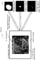
- FIG. 1 is a diagram briefly illustrating a position outputting process of a target according to an embodiment.
- the positions of the ellipse region, an ellipse region direction marker, and a target marker are specified by means of image segmentation as shown by a reference sign A2. Then, as indicated by the reference sign A3, the relative coordinates of the target to the ellipse region are specified by using the result of the image segmentation.
- the ellipse region may be any recess-free shape.
- the image segmentation may be achieved by a machine learning process.
- a characteristic structure in the ellipse region may be utilized to determine the orientation of the ellipse region.
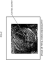
- FIG. 2 is a diagram illustrating an example of an image of fetal echocardiography used in the position outputting process of the target according to the embodiment.
- a cardiac position of a fetus as illustrated in FIG. 2 may be used.
- the cardiac position is the position near the atrial wall of the heart. If the fetus has a heart disease, the cardiac position is misaligned and therefore comes to be a key diagnostic aid marker.
- FIG. 4 is a diagram illustrating a segmentation process of FIG. 3
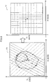
- FIG. 5 is a diagram illustrating a reference line specifying process and a center line specifying process of FIG. 3
- FIG. 6 is a diagram illustrating a rotating process of FIG. 3
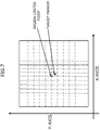
- FIG. 7 is a diagram illustrating positions of a region center point and a target marker on a coordinate plane in the position outputting process of the target according to the embodiment
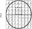
- FIG. 8 is a diagram illustrating a plot area table of the position outputting process of the target according to the embodiment.
- Step S1 segmentation of the ellipse region direction marker, the target marker, and the ellipse region is performed (Step S1). Specifically, the image segmentation is performed on the ellipse region direction marker (e.g., a spine of the fetus), the target marker (e.g., the cardiac position of the fetus), and the ellipse region (e.g., the body of the fetus) in an ultrasound image represented by a reference sign B1 of FIG. 4 by means of machine learning as indicated by a reference sign B2.
- the ellipse region direction marker e.g., a spine of the fetus
- the target marker e.g., the cardiac position of the fetus
- the ellipse region e.g., the body of the fetus
- Step S2 two points are determined through which a reference line that passes through the center of gravity of the ellipse region direction marker and that equally divides the area of the ellipse region into two (i.e., halves the area of the ellipse region) passes (Step S2).
- a reference line that passes through the center of gravity of the ellipse region direction marker and that equally divides the area of the ellipse region into two (i.e., halves the area of the ellipse region) passes.
- a reference line indicated by a broken line is specified on the X- and Y-axes plane.
- Intersections #1 at which the reference line intersects with the outer circumference of the ellipse region are determined (Step S3).
- two intersections #1 are specified as indicated by reference signs C2 and C3.
- Step S4 An ellipse-region center point between the two intersections of the reference line and the ellipse region is obtained (Step S4).
- the ellipse-region center point is specified as indicated by a reference sign C4.
- a center line that is orthogonal to the reference line at the ellipse-region center point is determined (Step S5).
- the center line represented by a thick line is specified.
- Intersections #2 at which the center line intersects with the outer circumference of the ellipse region are determined (Step S6).
- two intersections #2 are specified as indicated by a reference sign C6.
- grid lines #1 that equally divide the reference line within the outer circumference of the ellipse region into n are determined (Step S7).
- grid lines #1 including the center line and represented by one-dotted chain lines are specified.
- grid lines #2 that equally divide the center line within the outer circumference of the ellipse region into m are determined (Step S8).
- FIG. 5 as indicated by a reference sign C8, nine grid lines #2 represented by dotted lines and including the reference line are specified.
- the grid lines #1 and #2, target points, and the like are rotated such that the reference line comes to be parallel to the Y-axis (Step S9).
- the reference line represented by a broken line with a reference sign D1 of FIG. 6 is rotated, and the grid lines #1 and #2, the target points, and the like are rotated such that the reference line comes to be parallel to the Y-axis as indicated by a reference sign D2.
- the coordinates at which the target marker is positioned are specified (Step S10).
- the positions of the target marker and the region center point are specified.
- the position outputting process of the target ends.
- the position of the target marker is displayed in a plot area table. As indicated by a broken-line frame, the example of FIG. 8 displays the target marker positioned in an area defined by the coordinates (1, 1), (2, 1), (1, -1), and (2, -1).
- FIG. 9 is a block diagram schematically illustrating an example of a hardware configuration of an information processing apparatus 1 of the embodiment.
- the information processing apparatus 1 includes a CPU 11, a memory 12, a display controller 13, a storing device 14, an input interface (IF) 15, an external recording medium processor 16, and a communication IF 17.
- the memory 12 is an example of a storing unit, and is exemplified by a Read Only Memory (ROM) and a Random Access Memory (RAM) .
- ROM Read Only Memory
- RAM Random Access Memory
- a program such as a Basic Input/Output System (BIOS) may be written.
- BIOS Basic Input/Output System
- the software program in the memory 12 may be appropriately read and executed by the CPU 11.
- the RAM of the memory 12 may be used as a temporary recording memory or a working memory.
- the display controller 13 is connected to a displaying unit 130 and controls the displaying unit 130.
- the displaying unit 130 is, for example, a LCD, an Organic Light-Emitting Diode (OLED) display, a Cathode Ray Tube (CRT) display, or an electronic paper display, and displays various types of information to the operator.
- the displaying unit 130 may be combined with an input device, and may be a touch panel.
- Examples of the storing device 14 are a Dynamic Random Access Memory (DRAM), an SSD, a Storage Class Memory (SCM), and an HDD.
- DRAM Dynamic Random Access Memory
- SCM Storage Class Memory
- the input IF 15 may be connected to an input device such as a mouse 11 and/or a keyboard 152 and may control the input device such as the mouse 11 and/or the keyboard 152.
- the mouse 11 and the keyboard 152 are examples of the input device, and the operator makes various input operation through these input devices.
- the external recording medium processor 16 is configured to be mountable with a recording medium 160.
- the external recording medium processor 16 is configured to read, under a state of being mounted with the recording medium 160, information stored in the recording medium 160.
- the recording medium 160 is portable and is exemplified by a flexible disk, an optical disk, a magnetic disk, an optical-magnetic disk, or a semiconductor memory.
- the communication IF 17 is an interface that enables the information processing apparatus 1 to communicate with an external device(s).
- the CPU 11 is an example of a processor and is a processing apparatus that carries out various controls and arithmetic operations.
- the CPU 11 achieves various functions by executing an operating system (OS) and a program read into the memory 12.
- OS operating system
- the apparatus that controls the operation of the overall information processing apparatus 1 is not limited to the CPU 11, and may alternatively be either one of a Micro Processing Unit (MPU), a Digital Signal Processor (DSP), an Application Specific Integrated Circuit (ASIC), a Programmable Logic Device (PLD), and a Field Programmable Gate Array (FPGA).
- the apparatus that controls the operation of the overall information processing apparatus 1 may be a combination of two or more of a CPU, an MPU, a DSP, an ASIC, a PLD, and an FPGA.
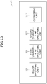
- FIG. 10 is a block diagram schematically illustrating an example of a software configuration of the information processing apparatus 1 of FIG. 9 .
- the CPU 11 of the information processing apparatus 1 functions as a region specifying unit 111, a first straight-line specifying unit 112, a second straight-line specifying unit 113, and an outputting unit 114.
- the region specifying unit 111 specifies the positions of the ellipse region direction marker, the target marker, and the ellipse region by image segmentation. In other words, the region specifying unit 111 specifies regions corresponding to a recess-free shape, and a detection target and a reference object included in the recess-free shape from a nondestructive inspection image.
- the first straight-line specifying unit 112 specifies the reference line and the grid lines #2 parallel to the reference line. In other words, the first straight-line specifying unit 112 specifies a first straight line (in other words, the reference line) that equally divides the region corresponding to the recess-free shape into two and that passes through the region corresponds to the reference object.
- the first straight-line specifying unit 112 may specify multiple second grid lines (in other words, the grid lines #2) that equally divide the second line (i.e., the center line) within the outer circumference of the recess-free shape into m (where m is a natural number of two or more).
- the second straight-line specifying unit 113 specifies the center line and the grid lines #1 parallel to the center line. In other words, the second-straight line specifying unit 113 determines the two intersection of the first straight line (in other words, the reference line) and the outer circumference of the recess-free shape, and specifies a second straight line (i.e., the center line) that passes through the center point of the determined two intersections and that is orthogonal to the first straight line.
- the second straight-line specifying unit 113 may specify multiple first grid lines (in other words, the grid lines #1) that equally divide the first straight line within the outer circumference of the recess-free shape into n (where n is a natural number of two or more).
- the outputting unit 114 rotates the coordinate plane, and outputs the coordinates on which the target marker is positioned. In other words, using the coordinate system using the first straight line and the second straight line as the axes, the outputting unit 114 outputs information indicating the position of the detection target in the nondestructive inspection image.
- the outputting unit 114 may output the information indicative of the position of the detection target after rotating the recess-free shape such that the first straight line comes to be parallel to one of the axes a predetermined axis of the coordinate system.
- the output unit 114 may output the information indicative of the position of the detection target in the coordinate system in a grid shape formed by the multiple first grid lines and the multiple second grid lines.
- the region specifying unit 111 specifies the regions corresponding to the recess-free shape, and the detection target and the reference object included in the recess-free shape from the nondestructive inspection image.
- the first straight-line specifying unit 112 divides the region corresponding to the recess-free shape into two segments and specifies the first straight line passing through the region corresponding to the reference object.
- the second-straight line specifying unit 113 obtains the two intersections of the first straight line and the outer circumference of the recess-free shape, and specifies the second straight line that passes through the center point of the determined two intersections and that is orthogonal to the first straight line.
- the outputting unit 114 uses the coordinate system using the first straight line and the second straight line as the axes to output information indicative of the position of the detection target in the nondestructive inspection image.
- the outputting unit 114 outputs the information indicative of the position of the detection target after rotating the recess-free shape such that the first straight line comes to be parallel to one of the axes of the coordinate system. This makes it easier for the inspector to recognize the position of the detection target.
- the second straight specifying unit 113 specifies the multiple first grid lines that equally divide the first line within the outer circumference of the recess-free shape into n (where, n is a natural number of two or more) .
- the first straight specifying unit 112 specifies the multiple second grid lines that equally divide the second line within the outer circumference of the recess-free shape into m (where, m is a natural number of two or more).
- the output unit 114 may output information indicative of the position of the detection target in the coordinate system in a grid shape formed by the multiple first grid lines and the multiple second grid lines. Consequently, the position of the inspection target object is output on the plot area table, so that the inspector can easily recognize the position of the detection target.
- the recess-free shape is a fetus
- the detection target is a heart of the fetus
- the reference object is a spine of the fetus.
- the position outputting process of a target is performed on the image acquired by the ultrasonic inspection of a heart of a fetus, but the target of the position outputting process is not limited to this.
- the position outputting process of a target may be performed on the heart of an adult or a fetus, or may be performed on various organs and the like in various organisms including humans.
- the position output processing of a target may be applied to an internal inspection of a housing of a product at the time of factory shipment, periodic inspection, or the like.
- a method used for capturing images is not limited to ultrasonography, and may alternatively use various nondestructive inspections such as a Magnetic Resonance Imaging (MRI) inspection, a Computed Tomography (CT) inspection, and a mammography inspection.
- MRI Magnetic Resonance Imaging
- CT Computed Tomography
- mammography inspection a method used for capturing images is not limited to ultrasonography, and may alternatively use various nondestructive inspections such as a Magnetic Resonance Imaging (MRI) inspection, a Computed Tomography (CT) inspection, and a mammography inspection.
- MRI Magnetic Resonance Imaging
- CT Computed Tomography
Landscapes
- Engineering & Computer Science (AREA)
- Health & Medical Sciences (AREA)
- Physics & Mathematics (AREA)
- Life Sciences & Earth Sciences (AREA)
- Theoretical Computer Science (AREA)
- General Physics & Mathematics (AREA)
- Medical Informatics (AREA)
- General Health & Medical Sciences (AREA)
- Radiology & Medical Imaging (AREA)
- Nuclear Medicine, Radiotherapy & Molecular Imaging (AREA)
- Computer Vision & Pattern Recognition (AREA)
- Public Health (AREA)
- Veterinary Medicine (AREA)
- Molecular Biology (AREA)
- Surgery (AREA)
- Animal Behavior & Ethology (AREA)
- Heart & Thoracic Surgery (AREA)
- Pathology (AREA)
- Biophysics (AREA)
- Biomedical Technology (AREA)
- Multimedia (AREA)
- Quality & Reliability (AREA)
- Pregnancy & Childbirth (AREA)
- Gynecology & Obstetrics (AREA)
- Ultra Sonic Daignosis Equipment (AREA)
- Image Processing (AREA)
- Image Analysis (AREA)
Abstract
Description
- The embodiment discussed herein relates to an information processing program, an information processing apparatus, and a method for processing information.
- In an ultrasonic inspection, a demand sometimes arises for grasping the relative position of a particular target to the entire object within a cross-section of the object.
- For example, in ultrasonic diagnosis of a fetus, if the relative position of an organ such as the heart to the whole body can be known, the diagnosis can be useful for early detection of a disease. Besides, in an internal inspection of a clay pipe that stores the communication wiring or the like, if the position of the wiring or the like can be known, the inspection can verify whether or not the wiring or the like has distortion.
- [Patent Document 1]
Japanese Laid-open Patent Publication No. 2020-113083 - If the relative position of a specific target in the cross-section of an object to the entire object is not precisely recognized, there is a possibility of not precisely being able to evaluate the soundness or the like of the object of the inspection target.
- As an aspect, one of the objects is to precisely evaluate the soundness or the like of the object of the inspection target.
- According to an aspect of the embodiments, an information processing program causes a computer to execute a process including: specifying a first region, a second region and third region from a nondestructive inspection image, the first region corresponding to a recess-free shape, the second region corresponding to a detection target included in the recess-free shape, the third region corresponding to a reference object included in the recess-free shape from a nondestructive inspection image; specifying a first straight line that divides the first region into two and that passes through the third region; obtaining two intersections of the first straight line and an outer circumference of the recess-free shape; specifying a second straight line that passes through a center point of the two points and that is orthogonal to the first straight line; and outputting information indicative of a position of the detection target in the nondestructive inspection image, using a coordinate system using the first straight line and the second straight line as axes.
- As one aspect, the soundness or the like of the object of the inspection target can be precisely evaluated.
-
-
FIG. 1 is a diagram briefly illustrating a position outputting process of a target according to an embodiment; -
FIG. 2 is a diagram illustrating an example of an image of fetal echocardiography used in the position outputting process of the target according to the embodiment; -
FIG. 3 is a flow diagram illustrating the position outputting process of the target according to the embodiment; -
FIG. 4 is a diagram illustrating a segmentation process ofFIG. 3 ; -
FIG. 5 is a diagram illustrating a reference line specifying process and a center line specifying process ofFIG. 3 ; -
FIG. 6 is a diagram illustrating a rotating process ofFIG. 3 ; -
FIG. 7 is a diagram illustrating positions of a region center point and a target marker on a coordinate plane in the position outputting process of the target according to the embodiment; -
FIG. 8 is a diagram illustrating a plot area table of the position outputting process of the target according to the embodiment; -
FIG. 9 is a block diagram schematically illustrating an example of a hardware configuration of an information processing apparatus of the embodiment; and -
FIG. 10 is a block diagram schematically illustrating an example of a software configuration of the information processing apparatus ofFIG. 9 . - Hereinafter, an embodiment of the present invention will now be described with reference to the accompanying drawings. However, the embodiment described below is merely illustrative and there is no intention to exclude the application of various modifications and techniques that are not explicitly described in the embodiment. For example, the present embodiment can be variously modified and implemented without departing from the scope thereof. Each drawing may include additional functions in addition to the elements appearing on the drawing.
- Like reference numbers designate the same or similar parts in the drawing, so repetitious description is omitted here.
-
FIG. 1 is a diagram briefly illustrating a position outputting process of a target according to an embodiment. - For a target in an ellipse region imaged by a nondestructive inspection such as ultrasonic inspection as indicated by a reference sign Al, the positions of the ellipse region, an ellipse region direction marker, and a target marker are specified by means of image segmentation as shown by a reference sign A2. Then, as indicated by the reference sign A3, the relative coordinates of the target to the ellipse region are specified by using the result of the image segmentation. The ellipse region may be any recess-free shape.
- The image segmentation may be achieved by a machine learning process. A characteristic structure in the ellipse region may be utilized to determine the orientation of the ellipse region.
-
FIG. 2 is a diagram illustrating an example of an image of fetal echocardiography used in the position outputting process of the target according to the embodiment. - As the target of the position outputting process, a cardiac position of a fetus as illustrated in
FIG. 2 may be used. The cardiac position is the position near the atrial wall of the heart. If the fetus has a heart disease, the cardiac position is misaligned and therefore comes to be a key diagnostic aid marker. - The position outputting process of the target according to the embodiment will be described along the flow diagram (Steps S1 to S10) of
FIG. 3 with reference toFIGs. 4-8 .FIG. 4 is a diagram illustrating a segmentation process ofFIG. 3 ;FIG. 5 is a diagram illustrating a reference line specifying process and a center line specifying process ofFIG. 3 ;FIG. 6 is a diagram illustrating a rotating process ofFIG. 3 ;FIG. 7 is a diagram illustrating positions of a region center point and a target marker on a coordinate plane in the position outputting process of the target according to the embodiment; andFIG. 8 is a diagram illustrating a plot area table of the position outputting process of the target according to the embodiment. - First, segmentation of the ellipse region direction marker, the target marker, and the ellipse region is performed (Step S1). Specifically, the image segmentation is performed on the ellipse region direction marker (e.g., a spine of the fetus), the target marker (e.g., the cardiac position of the fetus), and the ellipse region (e.g., the body of the fetus) in an ultrasound image represented by a reference sign B1 of
FIG. 4 by means of machine learning as indicated by a reference sign B2. - Then, two points are determined through which a reference line that passes through the center of gravity of the ellipse region direction marker and that equally divides the area of the ellipse region into two (i.e., halves the area of the ellipse region) passes (Step S2). In
FIG. 5 , as shown by a reference sign C1, the reference line indicated by a broken line is specified on the X- and Y-axes plane. -
Intersections # 1 at which the reference line intersects with the outer circumference of the ellipse region are determined (Step S3). InFIG. 5 , twointersections # 1 are specified as indicated by reference signs C2 and C3. - An ellipse-region center point between the two intersections of the reference line and the ellipse region is obtained (Step S4). In
FIG. 5 , the ellipse-region center point is specified as indicated by a reference sign C4. - A center line that is orthogonal to the reference line at the ellipse-region center point is determined (Step S5). In
FIG. 5 , as indicated by a reference sign C5, the center line represented by a thick line is specified. -
Intersections # 2 at which the center line intersects with the outer circumference of the ellipse region are determined (Step S6). InFIG. 5 , twointersections # 2 are specified as indicated by a reference sign C6. - Then,
grid lines # 1 that equally divide the reference line within the outer circumference of the ellipse region into n are determined (Step S7). InFIG. 5 , as indicated by a reference sign C7, ninegrid lines # 1 including the center line and represented by one-dotted chain lines are specified. - In addition,
grid lines # 2 that equally divide the center line within the outer circumference of the ellipse region into m are determined (Step S8). InFIG. 5 , as indicated by a reference sign C8, ninegrid lines # 2 represented by dotted lines and including the reference line are specified. - The
grid lines # 1 and #2, target points, and the like are rotated such that the reference line comes to be parallel to the Y-axis (Step S9). Specifically, the reference line represented by a broken line with a reference sign D1 ofFIG. 6 is rotated, and thegrid lines # 1 and #2, the target points, and the like are rotated such that the reference line comes to be parallel to the Y-axis as indicated by a reference sign D2. - The coordinates at which the target marker is positioned are specified (Step S10). In
FIG. 7 , under a state where the grid lines are parallel to the X-axis or the Y-axis, the positions of the target marker and the region center point are specified. Then, the position outputting process of the target ends. InFIG. 8 , the position of the target marker is displayed in a plot area table. As indicated by a broken-line frame, the example ofFIG. 8 displays the target marker positioned in an area defined by the coordinates (1, 1), (2, 1), (1, -1), and (2, -1). -
FIG. 9 is a block diagram schematically illustrating an example of a hardware configuration of aninformation processing apparatus 1 of the embodiment. - As illustrated in
FIG. 9 , theinformation processing apparatus 1 includes aCPU 11, amemory 12, adisplay controller 13, a storingdevice 14, an input interface (IF) 15, an externalrecording medium processor 16, and a communication IF 17. - The
memory 12 is an example of a storing unit, and is exemplified by a Read Only Memory (ROM) and a Random Access Memory (RAM) . Into the ROM of thememory 12, a program such as a Basic Input/Output System (BIOS) may be written. The software program in thememory 12 may be appropriately read and executed by theCPU 11. The RAM of thememory 12 may be used as a temporary recording memory or a working memory. - The
display controller 13 is connected to a displayingunit 130 and controls the displayingunit 130. The displayingunit 130 is, for example, a LCD, an Organic Light-Emitting Diode (OLED) display, a Cathode Ray Tube (CRT) display, or an electronic paper display, and displays various types of information to the operator. The displayingunit 130 may be combined with an input device, and may be a touch panel. - Examples of the storing
device 14 are a Dynamic Random Access Memory (DRAM), an SSD, a Storage Class Memory (SCM), and an HDD. - The input IF 15 may be connected to an input device such as a
mouse 11 and/or akeyboard 152 and may control the input device such as themouse 11 and/or thekeyboard 152. Themouse 11 and thekeyboard 152 are examples of the input device, and the operator makes various input operation through these input devices. - The external
recording medium processor 16 is configured to be mountable with arecording medium 160. The externalrecording medium processor 16 is configured to read, under a state of being mounted with therecording medium 160, information stored in therecording medium 160. In this embodiment, therecording medium 160 is portable and is exemplified by a flexible disk, an optical disk, a magnetic disk, an optical-magnetic disk, or a semiconductor memory. - The communication IF 17 is an interface that enables the
information processing apparatus 1 to communicate with an external device(s). - The
CPU 11 is an example of a processor and is a processing apparatus that carries out various controls and arithmetic operations. TheCPU 11 achieves various functions by executing an operating system (OS) and a program read into thememory 12. - The apparatus that controls the operation of the overall
information processing apparatus 1 is not limited to theCPU 11, and may alternatively be either one of a Micro Processing Unit (MPU), a Digital Signal Processor (DSP), an Application Specific Integrated Circuit (ASIC), a Programmable Logic Device (PLD), and a Field Programmable Gate Array (FPGA). The apparatus that controls the operation of the overallinformation processing apparatus 1 may be a combination of two or more of a CPU, an MPU, a DSP, an ASIC, a PLD, and an FPGA. -
FIG. 10 is a block diagram schematically illustrating an example of a software configuration of theinformation processing apparatus 1 ofFIG. 9 . - The
CPU 11 of theinformation processing apparatus 1 functions as aregion specifying unit 111, a first straight-line specifying unit 112, a second straight-line specifying unit 113, and anoutputting unit 114. - The
region specifying unit 111 specifies the positions of the ellipse region direction marker, the target marker, and the ellipse region by image segmentation. In other words, theregion specifying unit 111 specifies regions corresponding to a recess-free shape, and a detection target and a reference object included in the recess-free shape from a nondestructive inspection image. - The first straight-
line specifying unit 112 specifies the reference line and thegrid lines # 2 parallel to the reference line. In other words, the first straight-line specifying unit 112 specifies a first straight line (in other words, the reference line) that equally divides the region corresponding to the recess-free shape into two and that passes through the region corresponds to the reference object. The first straight-line specifying unit 112 may specify multiple second grid lines (in other words, the grid lines #2) that equally divide the second line (i.e., the center line) within the outer circumference of the recess-free shape into m (where m is a natural number of two or more). - The second straight-
line specifying unit 113 specifies the center line and thegrid lines # 1 parallel to the center line. In other words, the second-straightline specifying unit 113 determines the two intersection of the first straight line (in other words, the reference line) and the outer circumference of the recess-free shape, and specifies a second straight line (i.e., the center line) that passes through the center point of the determined two intersections and that is orthogonal to the first straight line. The second straight-line specifying unit 113 may specify multiple first grid lines (in other words, the grid lines #1) that equally divide the first straight line within the outer circumference of the recess-free shape into n (where n is a natural number of two or more). - The outputting
unit 114 rotates the coordinate plane, and outputs the coordinates on which the target marker is positioned. In other words, using the coordinate system using the first straight line and the second straight line as the axes, the outputtingunit 114 outputs information indicating the position of the detection target in the nondestructive inspection image. The outputtingunit 114 may output the information indicative of the position of the detection target after rotating the recess-free shape such that the first straight line comes to be parallel to one of the axes a predetermined axis of the coordinate system. Theoutput unit 114 may output the information indicative of the position of the detection target in the coordinate system in a grid shape formed by the multiple first grid lines and the multiple second grid lines. - Hereinafter, effects that can be achieved by the information processing program, the
information processing apparatus 1, and the method for processing information according to the embodiment will now be described. - The
region specifying unit 111 specifies the regions corresponding to the recess-free shape, and the detection target and the reference object included in the recess-free shape from the nondestructive inspection image. The first straight-line specifying unit 112 divides the region corresponding to the recess-free shape into two segments and specifies the first straight line passing through the region corresponding to the reference object. The second-straightline specifying unit 113 obtains the two intersections of the first straight line and the outer circumference of the recess-free shape, and specifies the second straight line that passes through the center point of the determined two intersections and that is orthogonal to the first straight line. Using the coordinate system using the first straight line and the second straight line as the axes, the outputtingunit 114 outputs information indicative of the position of the detection target in the nondestructive inspection image. With this configuration, the soundness of the object of an inspection target can be precisely evaluated. - The outputting
unit 114 outputs the information indicative of the position of the detection target after rotating the recess-free shape such that the first straight line comes to be parallel to one of the axes of the coordinate system. This makes it easier for the inspector to recognize the position of the detection target. - The second straight specifying
unit 113 specifies the multiple first grid lines that equally divide the first line within the outer circumference of the recess-free shape into n (where, n is a natural number of two or more) . The first straight specifyingunit 112 specifies the multiple second grid lines that equally divide the second line within the outer circumference of the recess-free shape into m (where, m is a natural number of two or more). Theoutput unit 114 may output information indicative of the position of the detection target in the coordinate system in a grid shape formed by the multiple first grid lines and the multiple second grid lines. Consequently, the position of the inspection target object is output on the plot area table, so that the inspector can easily recognize the position of the detection target. - The recess-free shape is a fetus, the detection target is a heart of the fetus, and the reference object is a spine of the fetus. As a result, the soundness and the like of the heart of the fetus can be precisely evaluated.
- The disclosed techniques are not limited to the embodiment described above, and may be variously modified without departing from the scope of the present embodiment. The respective configurations and processes of the present embodiment can be selected, omitted, and combined according to the requirement.
- In the embodiment described above, the position outputting process of a target is performed on the image acquired by the ultrasonic inspection of a heart of a fetus, but the target of the position outputting process is not limited to this. The position outputting process of a target may be performed on the heart of an adult or a fetus, or may be performed on various organs and the like in various organisms including humans. Alternatively, the position output processing of a target may be applied to an internal inspection of a housing of a product at the time of factory shipment, periodic inspection, or the like.
- A method used for capturing images is not limited to ultrasonography, and may alternatively use various nondestructive inspections such as a Magnetic Resonance Imaging (MRI) inspection, a Computed Tomography (CT) inspection, and a mammography inspection.
Claims (12)
- An information processing program for causing a computer to execute a process comprising:specifying a first region, a second region and third region from a nondestructive inspection image, the first region corresponding to a recess-free shape, the second region corresponding to a detection target included in the recess-free shape, the third region corresponding to a reference object included in the recess-free shape from a nondestructive inspection image;specifying a first straight line that divides the first region into two and that passes through the third region;obtaining two intersections of the first straight line and an outer circumference of the recess-free shape;specifying a second straight line that passes through a center point of the two points and that is orthogonal to the first straight line; andoutputting information indicative of a position of the detection target in the nondestructive inspection image, using a coordinate system using the first straight line and the second straight line as axes.
- The information processing program according to claim 1, wherein the process further comprises outputting the information indicative of the position of the detection target after rotating the recess-free shape such that the first straight line comes to be parallel to one of the axes of the coordinate system.
- The information processing program according to claim 1 or 2, wherein the process further comprises:specifying a plurality of first grid lines that divide the first straight line within the outer circumference of the recess-free shape into n (where, n is a natural number of two or more);specifying a plurality of second grid lines that divide the second straight line within the outer circumference of the recess-free shape into m (where, m is a natural number of two or more); andoutputting the information indicative of the position of the detection target in the coordinate system being in a grid shape formed by the plurality of first grid lines and the plurality of second grid lines.
- The information processing program according to one of claims 1-3, wherein:the recess-free shape is a fetus;the detection target is a heart of the fetus; andthe reference object is a spine of the fetus.
- An information processing apparatus comprising:a memory; anda processor coupled to the memory, the processor being configured to:specify a first region, a second region and third region from a nondestructive inspection image, the first region corresponding to a recess-free shape, the second region corresponding to a detection target included in the recess-free shape, the third region corresponding to a reference object included in the recess-free shape from a nondestructive inspection image;specify a first straight line that divides the first region into two and that passes through the third region;obtain two intersections of the first straight line and an outer circumference of the recess-free shape;specify a second straight line that passes through a center point of the two points and that is orthogonal to the first straight line; andoutput information indicative of a position of the detection target in the nondestructive inspection image, using a coordinate system using the first straight line and the second straight line as axes.
- The information processing apparatus according to claim 5, wherein the processor is further configured to output the information indicative of the position of the detection target after rotating the recess-free shape such that the first straight line comes to be parallel to one of the axes of the coordinate system.
- The information processing apparatus according to claim 5 or 6, wherein the processor is further configured to:specify a plurality of first grid lines that divide the first straight line within the outer circumference of the recess-free shape into n (where, n is a natural number of two or more);specify a plurality of second grid lines that divide the second straight line within the outer circumference of the recess-free shape into m (where, m is a natural number of two or more); andoutput the information indicative of the position of the detection target in the coordinate system being in a grid shape formed by the plurality of first grid lines and the plurality of second grid lines.
- The information processing apparatus according to one of claims 5-7, wherein:the recess-free shape is a fetus;the detection target is a heart of the fetus; andthe reference object is a spine of the fetus.
- A computer-implemented method for processing information comprising:specifying a first region, a second region and third region from a nondestructive inspection image, the first region corresponding to a recess-free shape, the second region corresponding to a detection target included in the recess-free shape, the third region corresponding to a reference object included in the recess-free shape from a nondestructive inspection image;specifying a first straight line that divides the first region into two and that passes through the third region;obtaining two intersections of the first straight line and an outer circumference of the recess-free shape;specifying a second straight line that passes through a center point of the two points and that is orthogonal to the first straight line; andoutputting information indicative of a position of the detection target in the nondestructive inspection image, using a coordinate system using the first straight line and the second straight line as axes.
- The computer-implemented method according to claim 9, wherein the method further comprises outputting the information indicative of the position of the detection target after rotating the recess-free shape such that the first straight line comes to be parallel to one of the axes of the coordinate system.
- The computer-implemented method according to claim 9 or 10, wherein the method further comprises:specifying a plurality of first grid lines that divide the first straight line within the outer circumference of the recess-free shape into n (where, n is a natural number of two or more);specifying a plurality of second grid lines that divide the second straight line within the outer circumference of the recess-free shape into m (where, m is a natural number of two or more); andoutputting the information indicative of the position of the detection target in the coordinate system being in a grid shape formed by the plurality of first grid lines and the plurality of second grid lines.
- The computer-implemented method according to one of claims 9-11, wherein:the recess-free shape is a fetus;the detection target is a heart of the fetus; andthe reference object is a spine of the fetus.
Applications Claiming Priority (1)
| Application Number | Priority Date | Filing Date | Title |
|---|---|---|---|
| JP2021097535A JP7692559B2 (en) | 2021-06-10 | 2021-06-10 | Information processing program, information processing device, and information processing method |
Publications (2)
| Publication Number | Publication Date |
|---|---|
| EP4101392A1 true EP4101392A1 (en) | 2022-12-14 |
| EP4101392B1 EP4101392B1 (en) | 2024-05-01 |
Family
ID=81850893
Family Applications (1)
| Application Number | Title | Priority Date | Filing Date |
|---|---|---|---|
| EP22175763.6A Active EP4101392B1 (en) | 2021-06-10 | 2022-05-27 | Information processing program, information processing apparatus, and method for processing information |
Country Status (3)
| Country | Link |
|---|---|
| US (1) | US12315151B2 (en) |
| EP (1) | EP4101392B1 (en) |
| JP (1) | JP7692559B2 (en) |
Citations (4)
| Publication number | Priority date | Publication date | Assignee | Title |
|---|---|---|---|---|
| US20100099987A1 (en) * | 2008-10-16 | 2010-04-22 | Takuya Sasaki | Ultrasonic diagnostic device, ultrasonic image processing apparatus, ultrasonic image acquiring method and ultrasonic diagnosis display method |
| US20200155114A1 (en) * | 2018-11-15 | 2020-05-21 | Samsung Medison Co., Ltd. | Ultrasound diagnosis apparatus for determining abnormality of fetal heart, and operating method thereof |
| US20200202551A1 (en) * | 2017-05-11 | 2020-06-25 | Koninklijke Philips N.V. | Fetal development monitoring |
| JP2020113083A (en) | 2019-01-11 | 2020-07-27 | 富士通株式会社 | Learning program, learning device, and learning method |
Family Cites Families (3)
| Publication number | Priority date | Publication date | Assignee | Title |
|---|---|---|---|---|
| JP4607263B2 (en) | 1998-11-30 | 2011-01-05 | 東芝医用システムエンジニアリング株式会社 | Contour tracking device |
| EP3435324A1 (en) * | 2017-07-27 | 2019-01-30 | Koninklijke Philips N.V. | Fetal ultrasound image processing |
| US11170245B2 (en) | 2019-06-21 | 2021-11-09 | StraxCorp Pty. Ltd. | Method and system for selecting a region of interest in an image |
-
2021
- 2021-06-10 JP JP2021097535A patent/JP7692559B2/en active Active
-
2022
- 2022-05-27 EP EP22175763.6A patent/EP4101392B1/en active Active
- 2022-05-27 US US17/826,159 patent/US12315151B2/en active Active
Patent Citations (4)
| Publication number | Priority date | Publication date | Assignee | Title |
|---|---|---|---|---|
| US20100099987A1 (en) * | 2008-10-16 | 2010-04-22 | Takuya Sasaki | Ultrasonic diagnostic device, ultrasonic image processing apparatus, ultrasonic image acquiring method and ultrasonic diagnosis display method |
| US20200202551A1 (en) * | 2017-05-11 | 2020-06-25 | Koninklijke Philips N.V. | Fetal development monitoring |
| US20200155114A1 (en) * | 2018-11-15 | 2020-05-21 | Samsung Medison Co., Ltd. | Ultrasound diagnosis apparatus for determining abnormality of fetal heart, and operating method thereof |
| JP2020113083A (en) | 2019-01-11 | 2020-07-27 | 富士通株式会社 | Learning program, learning device, and learning method |
Also Published As
| Publication number | Publication date |
|---|---|
| JP7692559B2 (en) | 2025-06-16 |
| EP4101392B1 (en) | 2024-05-01 |
| JP2022189138A (en) | 2022-12-22 |
| US20220398728A1 (en) | 2022-12-15 |
| US12315151B2 (en) | 2025-05-27 |
Similar Documents
| Publication | Publication Date | Title |
|---|---|---|
| CN102231963B (en) | Reparametrized bull's eye plots | |
| JP5364188B2 (en) | Non-line-of-sight reverse engineering for structural and system changes | |
| JP5027922B2 (en) | Ultrasonic diagnostic equipment | |
| JP7631179B2 (en) | Ultrasound diagnostic device and ultrasound image processing method | |
| CN116583224A (en) | Systems, methods and devices for quantitative assessment of organ mobility | |
| US20090299181A1 (en) | Diagnostic imaging apparatus and ultrasonic diagnostic apparatus | |
| JP2016028677A (en) | Medical image diagnostic apparatus and medical image processing apparatus | |
| JP5390149B2 (en) | Ultrasonic diagnostic apparatus, ultrasonic diagnostic support program, and image processing apparatus | |
| JP2024501181A (en) | Ultrasound image acquisition, tracking, and review | |
| US10621720B2 (en) | Deformable registration of magnetic resonance and ultrasound images using biomechanical models | |
| US8331638B2 (en) | Creation of motion compensated MRI M-mode images of the myocardial wall | |
| EP4101392B1 (en) | Information processing program, information processing apparatus, and method for processing information | |
| US8700126B2 (en) | System and method for computer aided septal defect diagnosis and surgery framework | |
| CN115187501A (en) | Systems, methods, and devices for identifying heterogeneous liver fat | |
| EP2289418A1 (en) | Ultrasound system and method for providing a plurality of slice plane images | |
| JP7475313B2 (en) | Ultrasound diagnostic system, ultrasound diagnostic device, and diagnostic support server | |
| JP2000276550A (en) | Medical diagnostic apparatus and method for checking activation of medical diagnostic application | |
| JP2001087228A (en) | Image interpretation support device | |
| JP7561027B2 (en) | Method and system for visually assisting an ultrasound system operator - Patents.com | |
| JP2024044923A (en) | Information processing device, information processing method, and information processing program | |
| JP6681778B2 (en) | Ultrasonic image display device and its control program | |
| EP4102457A1 (en) | Evaluating program, evaluating apparatus, and method for evaluating | |
| Zhou et al. | 3D reconstruction of the uterus and automatic segmentation of the uterine cavity on 3D magnetic resonance imaging: A preliminary study | |
| CN113808696B (en) | Ultrasonic data processing method, device, computer equipment and storage medium | |
| EP1776669A1 (en) | Imaging system |
Legal Events
| Date | Code | Title | Description |
|---|---|---|---|
| PUAI | Public reference made under article 153(3) epc to a published international application that has entered the european phase |
Free format text: ORIGINAL CODE: 0009012 |
|
| STAA | Information on the status of an ep patent application or granted ep patent |
Free format text: STATUS: THE APPLICATION HAS BEEN PUBLISHED |
|
| AK | Designated contracting states |
Kind code of ref document: A1 Designated state(s): AL AT BE BG CH CY CZ DE DK EE ES FI FR GB GR HR HU IE IS IT LI LT LU LV MC MK MT NL NO PL PT RO RS SE SI SK SM TR |
|
| STAA | Information on the status of an ep patent application or granted ep patent |
Free format text: STATUS: REQUEST FOR EXAMINATION WAS MADE |
|
| 17P | Request for examination filed |
Effective date: 20230404 |
|
| RBV | Designated contracting states (corrected) |
Designated state(s): AL AT BE BG CH CY CZ DE DK EE ES FI FR GB GR HR HU IE IS IT LI LT LU LV MC MK MT NL NO PL PT RO RS SE SI SK SM TR |
|
| GRAP | Despatch of communication of intention to grant a patent |
Free format text: ORIGINAL CODE: EPIDOSNIGR1 |
|
| STAA | Information on the status of an ep patent application or granted ep patent |
Free format text: STATUS: GRANT OF PATENT IS INTENDED |
|
| INTG | Intention to grant announced |
Effective date: 20231123 |
|
| GRAS | Grant fee paid |
Free format text: ORIGINAL CODE: EPIDOSNIGR3 |
|
| GRAA | (expected) grant |
Free format text: ORIGINAL CODE: 0009210 |
|
| STAA | Information on the status of an ep patent application or granted ep patent |
Free format text: STATUS: THE PATENT HAS BEEN GRANTED |
|
| AK | Designated contracting states |
Kind code of ref document: B1 Designated state(s): AL AT BE BG CH CY CZ DE DK EE ES FI FR GB GR HR HU IE IS IT LI LT LU LV MC MK MT NL NO PL PT RO RS SE SI SK SM TR |
|
| REG | Reference to a national code |
Ref country code: GB Ref legal event code: FG4D |
|
| REG | Reference to a national code |
Ref country code: CH Ref legal event code: EP |
|
| REG | Reference to a national code |
Ref country code: DE Ref legal event code: R096 Ref document number: 602022003164 Country of ref document: DE |
|
| REG | Reference to a national code |
Ref country code: IE Ref legal event code: FG4D |
|
| REG | Reference to a national code |
Ref country code: NL Ref legal event code: FP |
|
| REG | Reference to a national code |
Ref country code: LT Ref legal event code: MG9D |
|
| PG25 | Lapsed in a contracting state [announced via postgrant information from national office to epo] |
Ref country code: IS Free format text: LAPSE BECAUSE OF FAILURE TO SUBMIT A TRANSLATION OF THE DESCRIPTION OR TO PAY THE FEE WITHIN THE PRESCRIBED TIME-LIMIT Effective date: 20240901 |
|
| PG25 | Lapsed in a contracting state [announced via postgrant information from national office to epo] |
Ref country code: BG Free format text: LAPSE BECAUSE OF FAILURE TO SUBMIT A TRANSLATION OF THE DESCRIPTION OR TO PAY THE FEE WITHIN THE PRESCRIBED TIME-LIMIT Effective date: 20240501 |
|
| PG25 | Lapsed in a contracting state [announced via postgrant information from national office to epo] |
Ref country code: FI Free format text: LAPSE BECAUSE OF FAILURE TO SUBMIT A TRANSLATION OF THE DESCRIPTION OR TO PAY THE FEE WITHIN THE PRESCRIBED TIME-LIMIT Effective date: 20240501 Ref country code: HR Free format text: LAPSE BECAUSE OF FAILURE TO SUBMIT A TRANSLATION OF THE DESCRIPTION OR TO PAY THE FEE WITHIN THE PRESCRIBED TIME-LIMIT Effective date: 20240501 |
|
| PG25 | Lapsed in a contracting state [announced via postgrant information from national office to epo] |
Ref country code: GR Free format text: LAPSE BECAUSE OF FAILURE TO SUBMIT A TRANSLATION OF THE DESCRIPTION OR TO PAY THE FEE WITHIN THE PRESCRIBED TIME-LIMIT Effective date: 20240802 |
|
| PG25 | Lapsed in a contracting state [announced via postgrant information from national office to epo] |
Ref country code: PT Free format text: LAPSE BECAUSE OF FAILURE TO SUBMIT A TRANSLATION OF THE DESCRIPTION OR TO PAY THE FEE WITHIN THE PRESCRIBED TIME-LIMIT Effective date: 20240902 |
|
| REG | Reference to a national code |
Ref country code: AT Ref legal event code: MK05 Ref document number: 1681261 Country of ref document: AT Kind code of ref document: T Effective date: 20240501 |
|
| PG25 | Lapsed in a contracting state [announced via postgrant information from national office to epo] |
Ref country code: ES Free format text: LAPSE BECAUSE OF FAILURE TO SUBMIT A TRANSLATION OF THE DESCRIPTION OR TO PAY THE FEE WITHIN THE PRESCRIBED TIME-LIMIT Effective date: 20240501 |
|
| PG25 | Lapsed in a contracting state [announced via postgrant information from national office to epo] |
Ref country code: AT Free format text: LAPSE BECAUSE OF FAILURE TO SUBMIT A TRANSLATION OF THE DESCRIPTION OR TO PAY THE FEE WITHIN THE PRESCRIBED TIME-LIMIT Effective date: 20240501 |
|
| PG25 | Lapsed in a contracting state [announced via postgrant information from national office to epo] |
Ref country code: PL Free format text: LAPSE BECAUSE OF FAILURE TO SUBMIT A TRANSLATION OF THE DESCRIPTION OR TO PAY THE FEE WITHIN THE PRESCRIBED TIME-LIMIT Effective date: 20240501 |
|
| PG25 | Lapsed in a contracting state [announced via postgrant information from national office to epo] |
Ref country code: LV Free format text: LAPSE BECAUSE OF FAILURE TO SUBMIT A TRANSLATION OF THE DESCRIPTION OR TO PAY THE FEE WITHIN THE PRESCRIBED TIME-LIMIT Effective date: 20240501 |
|
| PG25 | Lapsed in a contracting state [announced via postgrant information from national office to epo] |
Ref country code: PT Free format text: LAPSE BECAUSE OF FAILURE TO SUBMIT A TRANSLATION OF THE DESCRIPTION OR TO PAY THE FEE WITHIN THE PRESCRIBED TIME-LIMIT Effective date: 20240902 Ref country code: PL Free format text: LAPSE BECAUSE OF FAILURE TO SUBMIT A TRANSLATION OF THE DESCRIPTION OR TO PAY THE FEE WITHIN THE PRESCRIBED TIME-LIMIT Effective date: 20240501 Ref country code: NO Free format text: LAPSE BECAUSE OF FAILURE TO SUBMIT A TRANSLATION OF THE DESCRIPTION OR TO PAY THE FEE WITHIN THE PRESCRIBED TIME-LIMIT Effective date: 20240801 Ref country code: LV Free format text: LAPSE BECAUSE OF FAILURE TO SUBMIT A TRANSLATION OF THE DESCRIPTION OR TO PAY THE FEE WITHIN THE PRESCRIBED TIME-LIMIT Effective date: 20240501 Ref country code: IS Free format text: LAPSE BECAUSE OF FAILURE TO SUBMIT A TRANSLATION OF THE DESCRIPTION OR TO PAY THE FEE WITHIN THE PRESCRIBED TIME-LIMIT Effective date: 20240901 Ref country code: HR Free format text: LAPSE BECAUSE OF FAILURE TO SUBMIT A TRANSLATION OF THE DESCRIPTION OR TO PAY THE FEE WITHIN THE PRESCRIBED TIME-LIMIT Effective date: 20240501 Ref country code: GR Free format text: LAPSE BECAUSE OF FAILURE TO SUBMIT A TRANSLATION OF THE DESCRIPTION OR TO PAY THE FEE WITHIN THE PRESCRIBED TIME-LIMIT Effective date: 20240802 Ref country code: FI Free format text: LAPSE BECAUSE OF FAILURE TO SUBMIT A TRANSLATION OF THE DESCRIPTION OR TO PAY THE FEE WITHIN THE PRESCRIBED TIME-LIMIT Effective date: 20240501 Ref country code: ES Free format text: LAPSE BECAUSE OF FAILURE TO SUBMIT A TRANSLATION OF THE DESCRIPTION OR TO PAY THE FEE WITHIN THE PRESCRIBED TIME-LIMIT Effective date: 20240501 Ref country code: BG Free format text: LAPSE BECAUSE OF FAILURE TO SUBMIT A TRANSLATION OF THE DESCRIPTION OR TO PAY THE FEE WITHIN THE PRESCRIBED TIME-LIMIT Effective date: 20240501 Ref country code: AT Free format text: LAPSE BECAUSE OF FAILURE TO SUBMIT A TRANSLATION OF THE DESCRIPTION OR TO PAY THE FEE WITHIN THE PRESCRIBED TIME-LIMIT Effective date: 20240501 Ref country code: RS Free format text: LAPSE BECAUSE OF FAILURE TO SUBMIT A TRANSLATION OF THE DESCRIPTION OR TO PAY THE FEE WITHIN THE PRESCRIBED TIME-LIMIT Effective date: 20240801 |
|
| PG25 | Lapsed in a contracting state [announced via postgrant information from national office to epo] |
Ref country code: DK Free format text: LAPSE BECAUSE OF FAILURE TO SUBMIT A TRANSLATION OF THE DESCRIPTION OR TO PAY THE FEE WITHIN THE PRESCRIBED TIME-LIMIT Effective date: 20240501 |
|
| PG25 | Lapsed in a contracting state [announced via postgrant information from national office to epo] |
Ref country code: LU Free format text: LAPSE BECAUSE OF NON-PAYMENT OF DUE FEES Effective date: 20240527 |
|
| PG25 | Lapsed in a contracting state [announced via postgrant information from national office to epo] |
Ref country code: EE Free format text: LAPSE BECAUSE OF FAILURE TO SUBMIT A TRANSLATION OF THE DESCRIPTION OR TO PAY THE FEE WITHIN THE PRESCRIBED TIME-LIMIT Effective date: 20240501 |
|
| PG25 | Lapsed in a contracting state [announced via postgrant information from national office to epo] |
Ref country code: CZ Free format text: LAPSE BECAUSE OF FAILURE TO SUBMIT A TRANSLATION OF THE DESCRIPTION OR TO PAY THE FEE WITHIN THE PRESCRIBED TIME-LIMIT Effective date: 20240501 |
|
| PG25 | Lapsed in a contracting state [announced via postgrant information from national office to epo] |
Ref country code: SK Free format text: LAPSE BECAUSE OF FAILURE TO SUBMIT A TRANSLATION OF THE DESCRIPTION OR TO PAY THE FEE WITHIN THE PRESCRIBED TIME-LIMIT Effective date: 20240501 Ref country code: RO Free format text: LAPSE BECAUSE OF FAILURE TO SUBMIT A TRANSLATION OF THE DESCRIPTION OR TO PAY THE FEE WITHIN THE PRESCRIBED TIME-LIMIT Effective date: 20240501 |
|
| PG25 | Lapsed in a contracting state [announced via postgrant information from national office to epo] |
Ref country code: SM Free format text: LAPSE BECAUSE OF FAILURE TO SUBMIT A TRANSLATION OF THE DESCRIPTION OR TO PAY THE FEE WITHIN THE PRESCRIBED TIME-LIMIT Effective date: 20240501 |
|
| PG25 | Lapsed in a contracting state [announced via postgrant information from national office to epo] |
Ref country code: SM Free format text: LAPSE BECAUSE OF FAILURE TO SUBMIT A TRANSLATION OF THE DESCRIPTION OR TO PAY THE FEE WITHIN THE PRESCRIBED TIME-LIMIT Effective date: 20240501 Ref country code: SK Free format text: LAPSE BECAUSE OF FAILURE TO SUBMIT A TRANSLATION OF THE DESCRIPTION OR TO PAY THE FEE WITHIN THE PRESCRIBED TIME-LIMIT Effective date: 20240501 Ref country code: RO Free format text: LAPSE BECAUSE OF FAILURE TO SUBMIT A TRANSLATION OF THE DESCRIPTION OR TO PAY THE FEE WITHIN THE PRESCRIBED TIME-LIMIT Effective date: 20240501 Ref country code: LU Free format text: LAPSE BECAUSE OF NON-PAYMENT OF DUE FEES Effective date: 20240527 Ref country code: EE Free format text: LAPSE BECAUSE OF FAILURE TO SUBMIT A TRANSLATION OF THE DESCRIPTION OR TO PAY THE FEE WITHIN THE PRESCRIBED TIME-LIMIT Effective date: 20240501 Ref country code: DK Free format text: LAPSE BECAUSE OF FAILURE TO SUBMIT A TRANSLATION OF THE DESCRIPTION OR TO PAY THE FEE WITHIN THE PRESCRIBED TIME-LIMIT Effective date: 20240501 Ref country code: CZ Free format text: LAPSE BECAUSE OF FAILURE TO SUBMIT A TRANSLATION OF THE DESCRIPTION OR TO PAY THE FEE WITHIN THE PRESCRIBED TIME-LIMIT Effective date: 20240501 Ref country code: MC Free format text: LAPSE BECAUSE OF FAILURE TO SUBMIT A TRANSLATION OF THE DESCRIPTION OR TO PAY THE FEE WITHIN THE PRESCRIBED TIME-LIMIT Effective date: 20240501 |
|
| REG | Reference to a national code |
Ref country code: DE Ref legal event code: R097 Ref document number: 602022003164 Country of ref document: DE |
|
| PG25 | Lapsed in a contracting state [announced via postgrant information from national office to epo] |
Ref country code: IT Free format text: LAPSE BECAUSE OF FAILURE TO SUBMIT A TRANSLATION OF THE DESCRIPTION OR TO PAY THE FEE WITHIN THE PRESCRIBED TIME-LIMIT Effective date: 20240501 |
|
| REG | Reference to a national code |
Ref country code: BE Ref legal event code: MM Effective date: 20240531 |
|
| PLBE | No opposition filed within time limit |
Free format text: ORIGINAL CODE: 0009261 |
|
| STAA | Information on the status of an ep patent application or granted ep patent |
Free format text: STATUS: NO OPPOSITION FILED WITHIN TIME LIMIT |
|
| 26N | No opposition filed |
Effective date: 20250204 |
|
| PG25 | Lapsed in a contracting state [announced via postgrant information from national office to epo] |
Ref country code: IE Free format text: LAPSE BECAUSE OF NON-PAYMENT OF DUE FEES Effective date: 20240527 |
|
| PG25 | Lapsed in a contracting state [announced via postgrant information from national office to epo] |
Ref country code: SI Free format text: LAPSE BECAUSE OF FAILURE TO SUBMIT A TRANSLATION OF THE DESCRIPTION OR TO PAY THE FEE WITHIN THE PRESCRIBED TIME-LIMIT Effective date: 20240501 Ref country code: BE Free format text: LAPSE BECAUSE OF NON-PAYMENT OF DUE FEES Effective date: 20240531 |
|
| PG25 | Lapsed in a contracting state [announced via postgrant information from national office to epo] |
Ref country code: HU Free format text: LAPSE BECAUSE OF FAILURE TO SUBMIT A TRANSLATION OF THE DESCRIPTION OR TO PAY THE FEE WITHIN THE PRESCRIBED TIME-LIMIT; INVALID AB INITIO Effective date: 20220527 |
|
| PG25 | Lapsed in a contracting state [announced via postgrant information from national office to epo] |
Ref country code: SE Free format text: LAPSE BECAUSE OF FAILURE TO SUBMIT A TRANSLATION OF THE DESCRIPTION OR TO PAY THE FEE WITHIN THE PRESCRIBED TIME-LIMIT Effective date: 20240501 |
|
| PG25 | Lapsed in a contracting state [announced via postgrant information from national office to epo] |
Ref country code: CY Free format text: LAPSE BECAUSE OF FAILURE TO SUBMIT A TRANSLATION OF THE DESCRIPTION OR TO PAY THE FEE WITHIN THE PRESCRIBED TIME-LIMIT; INVALID AB INITIO Effective date: 20220527 |
|
| REG | Reference to a national code |
Ref country code: CH Ref legal event code: H13 Free format text: ST27 STATUS EVENT CODE: U-0-0-H10-H13 (AS PROVIDED BY THE NATIONAL OFFICE) Effective date: 20251223 |
|
| PG25 | Lapsed in a contracting state [announced via postgrant information from national office to epo] |
Ref country code: CH Free format text: LAPSE BECAUSE OF NON-PAYMENT OF DUE FEES Effective date: 20250531 |
|
| PGFP | Annual fee paid to national office [announced via postgrant information from national office to epo] |
Ref country code: NL Payment date: 20260421 Year of fee payment: 5 |
|
| PG25 | Lapsed in a contracting state [announced via postgrant information from national office to epo] |
Ref country code: TR Free format text: LAPSE BECAUSE OF FAILURE TO SUBMIT A TRANSLATION OF THE DESCRIPTION OR TO PAY THE FEE WITHIN THE PRESCRIBED TIME-LIMIT Effective date: 20240501 |
|
| PG25 | Lapsed in a contracting state [announced via postgrant information from national office to epo] |
Ref country code: CH Free format text: THE PATENT HAS BEEN ANNULLED BY A DECISION OF A NATIONAL AUTHORITY Effective date: 20250531 |
|
| PG25 | Lapsed in a contracting state [announced via postgrant information from national office to epo] |
Ref country code: LT Free format text: LAPSE BECAUSE OF FAILURE TO SUBMIT A TRANSLATION OF THE DESCRIPTION OR TO PAY THE FEE WITHIN THE PRESCRIBED TIME-LIMIT Effective date: 20240501 |
|
| PGFP | Annual fee paid to national office [announced via postgrant information from national office to epo] |
Ref country code: DE Payment date: 20260421 Year of fee payment: 5 |
|
| PGFP | Annual fee paid to national office [announced via postgrant information from national office to epo] |
Ref country code: FR Payment date: 20260422 Year of fee payment: 5 |