EP4101282A1 - Residue spread mapping - Google Patents
Residue spread mapping Download PDFInfo
- Publication number
- EP4101282A1 EP4101282A1 EP22173139.1A EP22173139A EP4101282A1 EP 4101282 A1 EP4101282 A1 EP 4101282A1 EP 22173139 A EP22173139 A EP 22173139A EP 4101282 A1 EP4101282 A1 EP 4101282A1
- Authority
- EP
- European Patent Office
- Prior art keywords
- distribution
- environment
- region
- sub
- agricultural machine
- Prior art date
- Legal status (The legal status is an assumption and is not a legal conclusion. Google has not performed a legal analysis and makes no representation as to the accuracy of the status listed.)
- Granted
Links
Images


Classifications
-
- A—HUMAN NECESSITIES
- A01—AGRICULTURE; FORESTRY; ANIMAL HUSBANDRY; HUNTING; TRAPPING; FISHING
- A01D—HARVESTING; MOWING
- A01D41/00—Combines, i.e. harvesters or mowers combined with threshing devices
- A01D41/12—Details of combines
- A01D41/1243—Devices for laying-out or distributing the straw
-
- A—HUMAN NECESSITIES
- A01—AGRICULTURE; FORESTRY; ANIMAL HUSBANDRY; HUNTING; TRAPPING; FISHING
- A01B—SOIL WORKING IN AGRICULTURE OR FORESTRY; PARTS, DETAILS, OR ACCESSORIES OF AGRICULTURAL MACHINES OR IMPLEMENTS, IN GENERAL
- A01B79/00—Methods for working soil
- A01B79/005—Precision agriculture
-
- A—HUMAN NECESSITIES
- A01—AGRICULTURE; FORESTRY; ANIMAL HUSBANDRY; HUNTING; TRAPPING; FISHING
- A01D—HARVESTING; MOWING
- A01D41/00—Combines, i.e. harvesters or mowers combined with threshing devices
- A01D41/12—Details of combines
- A01D41/127—Control or measuring arrangements specially adapted for combines
-
- A—HUMAN NECESSITIES
- A01—AGRICULTURE; FORESTRY; ANIMAL HUSBANDRY; HUNTING; TRAPPING; FISHING
- A01F—PROCESSING OF HARVESTED PRODUCE; HAY OR STRAW PRESSES; DEVICES FOR STORING AGRICULTURAL OR HORTICULTURAL PRODUCE
- A01F12/00—Parts or details of threshing apparatus
- A01F12/40—Arrangements of straw crushers or cutters
-
- A—HUMAN NECESSITIES
- A01—AGRICULTURE; FORESTRY; ANIMAL HUSBANDRY; HUNTING; TRAPPING; FISHING
- A01F—PROCESSING OF HARVESTED PRODUCE; HAY OR STRAW PRESSES; DEVICES FOR STORING AGRICULTURAL OR HORTICULTURAL PRODUCE
- A01F29/00—Cutting apparatus specially adapted for cutting hay, straw or the like
- A01F29/09—Details
- A01F29/12—Discharge means
Definitions
- the present invention relates, in general, to systems and methods for monitoring residue spread from a harvesting machine.
- Agricultural combines work to cut crop material from a field before separating the grain from the material other than grain (MOG) (referred to interchangeably as "residue") on board.
- MOG material other than grain
- the grain is transferred to a grain bin of the combine (where it may be temporarily stored) and the MOG is deposited back onto the field.
- a second operation may be performed to gather the deposited MOG, or the MOG may be used as a fertiliser for the soil in the field. In either case, it is important for the MOG to be distributed evenly during deposition, in order to ensure an efficient second harvesting operation (e.g. bailing of the MOG) or to ensure effective fertilisation of the soil.
- residue should be spread consistently and managed to promote uniform rapid warming and drying in the spring for earlier planting and sufficient seed germination. It is also important not to spread MOG or residue into standing crop adjacent to the machine - i.e. the crop to be harvested on the next pass by the machine - as spreading into standing crop may result in the same area being spread twice causing an unwanted built of residue in a given area, again leading to uniformity issues.
- a system for mapping the distribution of residue material in an environment in which one or more agricultural machines are operable comprising: a sensing arrangement comprising one or more sensors mounted or otherwise coupled to an agricultural machine operating within the environment; and one or more controllers, configured to: receive sensor data from the one or more sensors indicative of residue material spread by a spreader tool of the agricultural machine; determine, from the sensor data, a local distribution of residue material associated with the spreader tool; and update a map of a global distribution of residue material across the environment in dependence on the local material distribution determined from the sensor data and the location of the agricultural machine, wherein updating the map of the global distribution comprises categorising one or more sub-regions within the environment in dependence on the determined local distribution.
- the present invention provides means to map the distribution of material across an environment such that appropriate actions can be taken in dependence thereon. This may include appropriate corrective actions and/or adjusting control of a follow up agricultural operation (e.g. baling or the like) to account for the distribution of residue in the environment.
- a follow up agricultural operation e.g. baling or the like
- global distribution is intended to cover the distribution of material across the mapped environment. This may be one or more harvested/harvestable fields, for example.
- the one or more sub-regions may comprise a bounding box about a region within the mapped environment assigned with a particular category. This may be termed a "polygonal" or "regional” mapping approach. Updating the map may include one or more of: generating a new sub-region within the mapped environment; reassigning a particular sub-region to a different category; and/or changing the size and/or shape of the sub-region within the mapped environment, for example where the local distribution is indicative of a change in residue distribution within the sub-region or within the area immediately adjacent to the sub-region such that the sub-region may effectively be extended to encompass such an area.
- Categorising may comprise assigning one of a plurality of categories to a sub-region of the environment in dependence on the determined local distribution at the location of the particular sub-region.
- the plurality of categories may include:
- the system e.g. the one or more controllers, may be operable to control one or more operating parameters of the agricultural machine or components thereof in dependence on the mapped distribution.
- the one or more controllers may be operable to control operating parameters related to the spreading of material from the machine, e.g. of a spreader tool of the machine, to control when material is distributed therefrom.
- the one or more controllers may be configured to prevent distribution of material as the agricultural machine passes areas of the environment corresponding to sub regions where material has previously been spread into standing crop. This may advantageously prevent overlapping of material spread to prevent or at least reduce areas of significant residue material build up.
- the system of the present aspect of the invention may be configured to control operation of a user interface, e.g. a display means, which may provide information, for example to an operator of the agricultural machine corresponding to the mapped distribution.
- a user interface e.g. a display means
- This may comprise providing a graphical representation of the mapped distribution.
- the graphical representation may comprise raw sensor data, or may preferably comprise a graphical illustration of the sensor data, for example as a two-dimensional map with the categorised sub-region(s) indicated therein.
- the sub-regions) may be highlighted using different colours, shades and/or patterns such that they are visually distinct from other regions in the representation of the mapped distribution.
- the user interface may comprise a user interface of the agricultural machine, such as a user terminal provided in the machine, e.g. in an operator cab of the machine.
- the user interface may comprise a display on a remote device, such as a smartphone, tablet computer, computer or the like.
- the user interface may comprise a user terminal on one or more further machines operating in the environment. For example, the information relating to the mapped distribution may in this manner be provided to an operator of a further machine to inform subsequent agricultural operation.
- the sensing arrangement may comprise an image sensor, such as a camera.
- the sensing arrangement may comprise a transceiver type sensor, having a transmitting component for transmitting a measurement signal and a receiving component for receiving reflected measurement signals.
- the sensor may comprise a RADAR sensor, LIDAR sensor, infrared sensor, or the like, for example.
- the sensing arrangement may comprise an ultrasonic sensor.
- the sensing arrangement may comprise multiple sensors, which may be of the same type or some combination of different sensor types.
- the system may include or be communicably coupled to a position module.
- the position module may be operable to provide information relating to the location of an associated agricultural machine within or with respect to the mapped environment.
- the positioning module may comprise or be part of a positioning system, such as a Global Navigation Satellite System (GNSS), e.g. GPS, GLONASS, Galileo or the like, and/or a local positioning system for determining the location of the agricultural machine within the environment.
- GNSS Global Navigation Satellite System
- GPS Global Navigation Satellite System
- GLONASS Global Navigation Satellite System
- Galileo Galileo
- the system may include or be communicably coupled to an inertial measurement unit.
- the inertial measurement unit may be used to determine an orientation of the agricultural machine within the environment.
- the system may comprise a distributed system.
- one or more components of the system may be located off-board from the agricultural machine. This may include one or more of the controller(s).
- This may include a storage means having the mapped distribution stored therein.
- the system may include a remote storage means, such as a remote server housing the mapped distribution,
- the system may include multiple agricultural machines, each comprising one or more sensors for obtaining sensor data.
- Each of the multiple agricultural machines may be communicable with a central processing means having the one or more controllers for performing the processing steps of the invention.
- a control system for mapping the distribution of residue material in an environment in which one or more agricultural machines are operable, the control system comprising one or more controllers, and being configured to: receive sensor data from a sensing arrangement comprising one or more sensors mounted or otherwise coupled to an agricultural machine operating within the environment, the sensor data being indicative of residue material spread by a spreader tool of the agricultural machine; determine, from the sensor data, a local distribution of residue material associated with the spreader tool; and update a map of a global distribution of residue material across the environment in dependence on the local material distribution determined from the sensor data and the location of the agricultural machine, wherein updating the map of the global distribution comprises categorising one or more sub-regions within the environment in dependence on the determined local distribution.
- the one or more controllers may collectively comprise an input (e.g. an electronic input) for receiving one or more input signals indicative of the sensor data.
- the one or more controllers may collectively comprise one or more processors (e.g. electronic processors) operable to execute computer readable instructions for controlling operation of the control system, for example to determine the local distribution and/or update the global distribution.
- the one or more processors may be operable to generate one or more control signals, for example for controlling output of a graphical representation of the global distribution, or for controlling operation of one or more agricultural machines within the environment.
- the one or more controllers may collectively comprise an output (e.g. an electronic output) for outputting the one or more control signals.
- the one or more controllers of the control system may be configured in any manner of the one or more controllers of the system described hereinabove with reference to the first aspect of the invention.
- a further aspect of the invention provides an agricultural machine comprising the system or control system of any preceding aspect of the invention.
- a method of mapping the distribution of residue material in an environment in which one or more agricultural machines are operable comprising: receiving sensor data from one or more sensors of a sensing arrangement mounted or otherwise coupled to an agricultural machine operating within the environment, the sensor data being indicative of residue material spread by a spreader tool of the agricultural machine; determining, from the sensor data, a local distribution of residue material associated with the spreader tool; and updating a map of a global distribution of residue material across the environment in dependence on the local material distribution determined from the sensor data and the location of the agricultural machine, wherein updating the map of the global distribution comprises categorising one or more sub-regions within the environment in dependence on the determined local distribution.
- the one or more sub-regions may comprise a bounding box about a region within the mapped environment assigned with a particular category. This may be termed a "polygonal" or "regional” mapping approach. Updating the map may include one or more of: generating a new sub-region within the mapped environment; reassigning a particular sub-region to a different category; and/or changing the size and/or shape of the sub-region within the mapped environment, for example where the local distribution is indicative of a change in residue distribution within the sub-region or within the area immediately adjacent to the sub-region such that the sub-region may effectively be extended to encompass such an area.
- Categorising may comprise assigning one of a plurality of categories to a sub-region of the environment in dependence on the determined local distribution at the location of the particular sub-region.
- the plurality of categories may include:
- the method may comprise controlling one or more operating parameters of the agricultural machine or components thereof in dependence on the mapped distribution.
- the method may comprise controlling one or more operating parameters related to the spreading of material from the machine, e.g. of a spreader tool of the machine, to control when material is distributed therefrom.
- the method may comprise preventing distribution of material as the agricultural machine passes areas of the environment corresponding to sub regions where material has previously been spread into standing crop. This may advantageously prevent overlapping of material spread to prevent or at least reduce areas of significant residue material build up.
- the method may comprise controlling operation of a user interface, e.g. a display means, to provide information, for example to an operator of the agricultural machine corresponding to the mapped global distribution.
- a user interface e.g. a display means
- This may comprise providing a graphical representation of the mapped distribution.
- the graphical representation may comprise raw sensor data, or may preferably comprise a graphical illustration of the sensor data, for example as a two-dimensional map with the categorised sub-region(s) indicated therein.
- the sub-region(s) may be highlighted using different colours, shades and/or patterns such that they are visually distinct from other regions in the representation of the mapped distribution.
- the user interface may comprise a user interface of the agricultural machine, such as a user terminal provided in the machine, e.g. in an operator cab of the machine.
- the user interface may comprise a display on a remote device, such as a smartphone, tablet computer, computer or the like.
- the user interface may comprise a user terminal on one or more further machines operating in the environment. For example, the information relating to the mapped distribution may in this manner be provided to an operator of a further machine to inform subsequent agricultural operation.
- the method may comprise obtaining information relating to the location of an associated agricultural machine within or with respect to the mapped environment.
- the method may comprise updating the mapped global distribution in dependence on the location of the agricultural machine.
- the method may comprise determining an orientation of the agricultural machine within the environment.
- the method may be performable utilising a distributed system.
- one or more components of the system may be located off-board from the agricultural machine. This may include a storage means having the mapped distribution stored therein.
- the system may include a remote storage means, such as a remote server housing the mapped distribution.
- Each of the multiple agricultural machines may be communicable with a central processing means having the one or more controllers for performing the processing steps of the invention.
- a further aspect of the invention provides a computer readable storage medium comprising the computer software of the preceding aspect of the invention.
- the storage medium comprises a non-transitory computer readable storage medium.
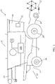
- Figure 1 illustrates an agricultural machine, and specifically a combine 10, embodying aspects of the present invention.
- the combine 10 is coupled to a header 12 which is operable, in use, to cut and gather a strip of crop material as the combine 10 is driven across a field / area to be harvested during a harvesting operation.
- a conveyor section 14 conveys the cut crop material from the header 12 into a crop processing apparatus 16 operable to separate grain and non-grain (i.e. material other than grain (MOG)) as will be appreciated.
- grain and non-grain i.e. material other than grain (MOG)
- apparatus for separating grain and non-grain material are well-known in the art and the present invention is not limited in this sense. The skilled person will appreciate that numerous different configurations for the crop processing apparatus may be used as appropriate. Clean grain separated from the cut crop material is collected in a grain bin 18, which may be periodically emptied, e.g.
- the combine 10 may also include a chopper tool positioned, for example, between the crop processing apparatus 16 and the spreader tool 22 and operable, in use, to cut the MOG/residue before it is spread by the spreader tool 22.
- the combine 10 also typically includes, amongst other features, an operator cab 26, wheels 28, engine (not shown) and a user interface 32.
- the combine 10 additionally includes a sensor 30 mounted to the rear of the combine 10 and having a sensing region rearwards of the combine 10 covering the area in which residue material is spread by the spreader tool 22.
- the sensor in the illustrated embodiment comprises a camera, although other types of imaging sensor may be used, and/or use of a transceiver type sensor is also envisaged, such as a LIDAR, RADAR or ultrasonic sensor, for example.
- the sensor 30 is sued, by a control system 100 of the combine 10 to determine one or more characteristics of a distribution of material associated with the spreader tool 22, hereinafter referred to as a local distribution.
- the local distribution determined using sensor 30 is used to update a map of a global distribution of residue material across the environment as a whole.
- control system 100 comprises a controller 102 having an electronic processor 104, an electronic input 106 and electronic output 110 and transceiver module 108.
- the processor 104 is operable to access a memory 112 of the controller 102 and execute instructions stored therein to perform the steps and functionality of the present invention discussed herein, e.g. by controlling the user interface 32, to provide a representation to an operator of the combine 10 illustrative of the determined global residue material distribution.
- the processor 104 is operable to receive sensor data via input 106 which, in the illustrated embodiment, takes the form of input signals 105 received from the sensor 30. utilising this data, the processor 104 is configured to analyse the data and extract therefrom a measure of a local material distribution associated with the spreader tool 22. In practice, this may involve determining a measure of an amount of residue material being spread in a central measurement region corresponding to the region defined by the width of the combine 10 (or header 12), and/or an amount of residue material being spread left or right of the combine 10, e.g. into adjacent standing crop or into an adjacent crop row, such as the row previously harvested. Analysis of the sensor data to extract the local residue distribution falls outside the scope of the present invention and the invention is not limited in this sense.
- the processor 104 is also operably coupled to a positioning module 34.
- the positioning module 34 forms part of a Global Navigation Satellite System (GNSS) and is operable to provide information relating to the location of the combine 10 within the mapped environment. Utilizing the location of the combine 10, the local distribution determined using sensor data from the sensor 30 can be related to a global distribution across the entire environment.
- GNSS Global Navigation Satellite System
- Output 110 is operably coupled to the user interface 32 of the combine 10.
- the control system 100 is operable to control operation of the user interface 32, e.g. through output of control signals 111 in order to display operational data to an operator of the combine 10 relating to the operation of the control system 100.
- the control system 100 is operable to control the user interface to display to the operator a graphical representation of a map of the global distribution of the MOG across the environment.
- FIGS 3A and 3B illustrate the operational use of the invention further.
- Figures 3A and 3B show representations 200, 300 of the mapped global distribution of residue material within an environment, here a field F, formed using the present invention.
- the representations 200, 300 may be shown as an image on a user interface, e.g. display 32 in the operator cab of the combine 10.
- the representations include multiple different sub-regions which are each classified in dependence on the local material distribution determined in the manner discussed herein, and their position with respect to a representation of the combine 10.
- the sub-regions A, B, C, D, E are delineated by bounding boxes and as such comprise polygonal sub-regions corresponding to locations in the field F having determined residue spread characteristics. Based on these characteristics the sub-regions are classified and the classifications are used to generate the representations 200, 300 in the manner discussed herein.
- the categories include:
- the processor 104 is operable to determine a local residue material distribution. Based on this, and with knowledge of the location of the combine 10 within the field F, as determined via positioning module 34, a determination is made on a measure of residue material being spread into at various locations within the field F. In turn, the processor 104 is configured to categorise locations within the field F based on the currently observed local distribution from the spreader tool 22 and knowledge of the category prior to the combine 10 spreading residue material at the corresponding location within the field F.
- the map of the global residue distribution may be continually updated as the combine 10 traverses the field F. Updating the map may include generating a new sub-region within the mapped environment. This may occur where the local material distribution as determined by the processor 104 is indicative of the spreader tool 22 beginning to spread material into an area which has previously been harvested, e.g. generating a new sub-region categorised as "D". Updating the map may include reassigning a particular sub-region to a different category.
- Updating the map may include changing the size and/or shape of the sub-region within the mapped environment, for example where the local distribution is indicative of a change in residue distribution within the sub-region or within the area immediately adjacent to the sub-region such that the sub-region may effectively be extended to encompass such an area.
- sub-regions within the representations 200, 300 are distinguished from one another using colour and pattern coding.
- a representation 200, 300 is produced which an operator may view and quickly determine areas within the field F where there is potentially significant build-up of residue material. This can be used to inform later harvesting operations, e.g. control over the speed and operation of further machines when operating in those areas, or indeed in some instances to perform a corrective action to make the distribution more uniform in those areas.
- the representation 200, 300 may be used to control future harvesting operations by the combine 10 on future passes of the field F.
- control over the spreader tool 22 may be possible on the next pass to prevent distribution altogether, or at least for the portion of the path of the next path corresponding to sub-region C. This may be an operator performing this task manually whilst viewing the representations 200, 300, or in some other embodiments may include active control over the spreader tool 22 itself.
- the present invention may provide a means to control distribution on the basis of the determined global distribution to reduce areas of significant residue material build up in the field F.
- the representation 200, 300 is displayed here as an overhead map of the field F in which the combine 10 is operating, or has operated, and is presented on the user interface 32 of the combine 10.
- the representation may be stored remotely, or be sent over a communication channel, such that it may be viewed on other interfaces, including on a remote device or user terminal of a further machine operating or operable in the field F.
- control system 100 housed within combine 10.
- control system 100 could be configured as a distributed system, with one or more components housed remotely, e.g. on further agricultural machines operating within the environment, on a remote server or the like.
- control system 100 is communicable with a remote server where the global distribution and the map thereof is stored and is accessible to multiple different operators.
- embodiments of the present invention can be realised in the form of hardware, software or a combination of hardware and software. Any such software may be stored in the form of volatile or non-volatile storage such as, for example, a storage device like a ROM, whether erasable or rewritable or not, or in the form of memory such as, for example, RAM, memory chips, device or integrated circuits or on an optically or magnetically readable medium such as, for example, a CD, DVD, magnetic disk or magnetic tape. It will be appreciated that the storage devices and storage media are embodiments of machine-readable storage that are suitable for storing a program or programs that, when executed, implement embodiments of the present invention.
- embodiments provide a program comprising code for implementing a system or method as set out herein and a machine readable storage storing such a program. Still further, embodiments of the present invention may be conveyed electronically via any medium such as a communication signal carried over a wired or wireless connection and embodiments suitably encompass the same.
Landscapes
- Life Sciences & Earth Sciences (AREA)
- Environmental Sciences (AREA)
- Engineering & Computer Science (AREA)
- Mechanical Engineering (AREA)
- Soil Sciences (AREA)
- Management, Administration, Business Operations System, And Electronic Commerce (AREA)
Abstract
Description
- The present invention relates, in general, to systems and methods for monitoring residue spread from a harvesting machine.
- Agricultural combines work to cut crop material from a field before separating the grain from the material other than grain (MOG) (referred to interchangeably as "residue") on board. Generally, the grain is transferred to a grain bin of the combine (where it may be temporarily stored) and the MOG is deposited back onto the field. A second operation may be performed to gather the deposited MOG, or the MOG may be used as a fertiliser for the soil in the field. In either case, it is important for the MOG to be distributed evenly during deposition, in order to ensure an efficient second harvesting operation (e.g. bailing of the MOG) or to ensure effective fertilisation of the soil. When residue is unevenly distributed over a field, not only are exposed areas at risk for erosion, but inconsistencies in soil temperatures and moisture also may cause uneven plant emergence the following year, hurting yield. Ideally, residue should be spread consistently and managed to promote uniform rapid warming and drying in the spring for earlier planting and sufficient seed germination. It is also important not to spread MOG or residue into standing crop adjacent to the machine - i.e. the crop to be harvested on the next pass by the machine - as spreading into standing crop may result in the same area being spread twice causing an unwanted built of residue in a given area, again leading to uniformity issues.
- It is an aim to improve upon known systems such that the distribution of material from an agricultural machine can be monitored and optionally corrected more effectively and efficiently.
- In an aspect of the invention there is provided a system for mapping the distribution of residue material in an environment in which one or more agricultural machines are operable, the system comprising: a sensing arrangement comprising one or more sensors mounted or otherwise coupled to an agricultural machine operating within the environment; and one or more controllers, configured to: receive sensor data from the one or more sensors indicative of residue material spread by a spreader tool of the agricultural machine; determine, from the sensor data, a local distribution of residue material associated with the spreader tool; and update a map of a global distribution of residue material across the environment in dependence on the local material distribution determined from the sensor data and the location of the agricultural machine, wherein updating the map of the global distribution comprises categorising one or more sub-regions within the environment in dependence on the determined local distribution.
- Advantageously, the present invention provides means to map the distribution of material across an environment such that appropriate actions can be taken in dependence thereon. This may include appropriate corrective actions and/or adjusting control of a follow up agricultural operation (e.g. baling or the like) to account for the distribution of residue in the environment.
- When used herein and throughout the specification the term "global distribution" is intended to cover the distribution of material across the mapped environment. This may be one or more harvested/harvestable fields, for example.
- The one or more sub-regions may comprise a bounding box about a region within the mapped environment assigned with a particular category. This may be termed a "polygonal" or "regional" mapping approach. Updating the map may include one or more of: generating a new sub-region within the mapped environment; reassigning a particular sub-region to a different category; and/or changing the size and/or shape of the sub-region within the mapped environment, for example where the local distribution is indicative of a change in residue distribution within the sub-region or within the area immediately adjacent to the sub-region such that the sub-region may effectively be extended to encompass such an area.
- Categorising may comprise assigning one of a plurality of categories to a sub-region of the environment in dependence on the determined local distribution at the location of the particular sub-region. The plurality of categories may include:
- (i) a region corresponding to unharvested crop;
- (ii) a region corresponding to harvested crop and where residue material has been spread;
- (iii) a region corresponding to standing crop (i.e. unharvested crop) but where material has been spread into, for example as the agricultural machine passed along an adjacent row in the environment; and/or
- (iv) a region corresponding to an area of harvested where residue material has been spread more than once, for example as the agricultural machine passes along an adjacent row in the environment.
- The system, e.g. the one or more controllers, may be operable to control one or more operating parameters of the agricultural machine or components thereof in dependence on the mapped distribution. For example, the one or more controllers may be operable to control operating parameters related to the spreading of material from the machine, e.g. of a spreader tool of the machine, to control when material is distributed therefrom. In embodiments, the one or more controllers may be configured to prevent distribution of material as the agricultural machine passes areas of the environment corresponding to sub regions where material has previously been spread into standing crop. This may advantageously prevent overlapping of material spread to prevent or at least reduce areas of significant residue material build up.
- In embodiments, the system of the present aspect of the invention may be configured to control operation of a user interface, e.g. a display means, which may provide information, for example to an operator of the agricultural machine corresponding to the mapped distribution. This may comprise providing a graphical representation of the mapped distribution. The graphical representation may comprise raw sensor data, or may preferably comprise a graphical illustration of the sensor data, for example as a two-dimensional map with the categorised sub-region(s) indicated therein. The sub-regions) may be highlighted using different colours, shades and/or patterns such that they are visually distinct from other regions in the representation of the mapped distribution.
- The user interface may comprise a user interface of the agricultural machine, such as a user terminal provided in the machine, e.g. in an operator cab of the machine. The user interface may comprise a display on a remote device, such as a smartphone, tablet computer, computer or the like. The user interface may comprise a user terminal on one or more further machines operating in the environment. For example, the information relating to the mapped distribution may in this manner be provided to an operator of a further machine to inform subsequent agricultural operation.
- The sensing arrangement may comprise an image sensor, such as a camera. The sensing arrangement may comprise a transceiver type sensor, having a transmitting component for transmitting a measurement signal and a receiving component for receiving reflected measurement signals. The sensor may comprise a RADAR sensor, LIDAR sensor, infrared sensor, or the like, for example. The sensing arrangement may comprise an ultrasonic sensor. The sensing arrangement may comprise multiple sensors, which may be of the same type or some combination of different sensor types.
- The system may include or be communicably coupled to a position module. The position module may be operable to provide information relating to the location of an associated agricultural machine within or with respect to the mapped environment. The positioning module may comprise or be part of a positioning system, such as a Global Navigation Satellite System (GNSS), e.g. GPS, GLONASS, Galileo or the like, and/or a local positioning system for determining the location of the agricultural machine within the environment.
- The system may include or be communicably coupled to an inertial measurement unit. The inertial measurement unit may be used to determine an orientation of the agricultural machine within the environment.
- The system may comprise a distributed system. For example, one or more components of the system may be located off-board from the agricultural machine. This may include one or more of the controller(s). This may include a storage means having the mapped distribution stored therein. For example, the system may include a remote storage means, such as a remote server housing the mapped distribution,
- The system may include multiple agricultural machines, each comprising one or more sensors for obtaining sensor data. Each of the multiple agricultural machines may be communicable with a central processing means having the one or more controllers for performing the processing steps of the invention.
- In a further aspect of the invention there is provided a control system for mapping the distribution of residue material in an environment in which one or more agricultural machines are operable, the control system comprising one or more controllers, and being configured to: receive sensor data from a sensing arrangement comprising one or more sensors mounted or otherwise coupled to an agricultural machine operating within the environment, the sensor data being indicative of residue material spread by a spreader tool of the agricultural machine; determine, from the sensor data, a local distribution of residue material associated with the spreader tool; and update a map of a global distribution of residue material across the environment in dependence on the local material distribution determined from the sensor data and the location of the agricultural machine, wherein updating the map of the global distribution comprises categorising one or more sub-regions within the environment in dependence on the determined local distribution.
- The one or more controllers may collectively comprise an input (e.g. an electronic input) for receiving one or more input signals indicative of the sensor data. The one or more controllers may collectively comprise one or more processors (e.g. electronic processors) operable to execute computer readable instructions for controlling operation of the control system, for example to determine the local distribution and/or update the global distribution. The one or more processors may be operable to generate one or more control signals, for example for controlling output of a graphical representation of the global distribution, or for controlling operation of one or more agricultural machines within the environment. The one or more controllers may collectively comprise an output (e.g. an electronic output) for outputting the one or more control signals.
- The one or more controllers of the control system may be configured in any manner of the one or more controllers of the system described hereinabove with reference to the first aspect of the invention.
- A further aspect of the invention provides an agricultural machine comprising the system or control system of any preceding aspect of the invention.
- In a further aspect of the invention there is provided a method of mapping the distribution of residue material in an environment in which one or more agricultural machines are operable, the method comprising: receiving sensor data from one or more sensors of a sensing arrangement mounted or otherwise coupled to an agricultural machine operating within the environment, the sensor data being indicative of residue material spread by a spreader tool of the agricultural machine; determining, from the sensor data, a local distribution of residue material associated with the spreader tool; and updating a map of a global distribution of residue material across the environment in dependence on the local material distribution determined from the sensor data and the location of the agricultural machine, wherein updating the map of the global distribution comprises categorising one or more sub-regions within the environment in dependence on the determined local distribution.
- The one or more sub-regions may comprise a bounding box about a region within the mapped environment assigned with a particular category. This may be termed a "polygonal" or "regional" mapping approach. Updating the map may include one or more of: generating a new sub-region within the mapped environment; reassigning a particular sub-region to a different category; and/or changing the size and/or shape of the sub-region within the mapped environment, for example where the local distribution is indicative of a change in residue distribution within the sub-region or within the area immediately adjacent to the sub-region such that the sub-region may effectively be extended to encompass such an area.
- Categorising may comprise assigning one of a plurality of categories to a sub-region of the environment in dependence on the determined local distribution at the location of the particular sub-region. The plurality of categories may include:
- (i) a region corresponding to unharvested crop;
- (ii) a region corresponding to harvested crop and where residue material has been spread;
- (iii) a region corresponding to standing crop (i.e. unharvested crop) but where material has been spread into, for example as the agricultural machine passed along an adjacent row in the environment; and/or
- (iv) a region corresponding to an area of harvested where residue material has been spread more than once, for example as the agricultural machine passes along an adjacent row in the environment.
- The method may comprise controlling one or more operating parameters of the agricultural machine or components thereof in dependence on the mapped distribution. For example, the method may comprise controlling one or more operating parameters related to the spreading of material from the machine, e.g. of a spreader tool of the machine, to control when material is distributed therefrom. In embodiments, the method may comprise preventing distribution of material as the agricultural machine passes areas of the environment corresponding to sub regions where material has previously been spread into standing crop. This may advantageously prevent overlapping of material spread to prevent or at least reduce areas of significant residue material build up.
- In embodiments, the method may comprise controlling operation of a user interface, e.g. a display means, to provide information, for example to an operator of the agricultural machine corresponding to the mapped global distribution. This may comprise providing a graphical representation of the mapped distribution. The graphical representation may comprise raw sensor data, or may preferably comprise a graphical illustration of the sensor data, for example as a two-dimensional map with the categorised sub-region(s) indicated therein. The sub-region(s) may be highlighted using different colours, shades and/or patterns such that they are visually distinct from other regions in the representation of the mapped distribution.
- The user interface may comprise a user interface of the agricultural machine, such as a user terminal provided in the machine, e.g. in an operator cab of the machine. The user interface may comprise a display on a remote device, such as a smartphone, tablet computer, computer or the like. The user interface may comprise a user terminal on one or more further machines operating in the environment. For example, the information relating to the mapped distribution may in this manner be provided to an operator of a further machine to inform subsequent agricultural operation.
- The method may comprise obtaining information relating to the location of an associated agricultural machine within or with respect to the mapped environment. The method may comprise updating the mapped global distribution in dependence on the location of the agricultural machine.
- The method may comprise determining an orientation of the agricultural machine within the environment.
- The method may be performable utilising a distributed system. For example, one or more components of the system may be located off-board from the agricultural machine. This may include a storage means having the mapped distribution stored therein. For example, the system may include a remote storage means, such as a remote server housing the mapped distribution.
- There may be multiple agricultural machines, each comprising one or more sensors for obtaining sensor data. Each of the multiple agricultural machines may be communicable with a central processing means having the one or more controllers for performing the processing steps of the invention.
- In a further aspect of the invention there is provided computer software comprising computer readable instructions which, when executed by one or more processors, causes performance of the method of the preceding aspect of the invention.
- A further aspect of the invention provides a computer readable storage medium comprising the computer software of the preceding aspect of the invention. Optionally, the storage medium comprises a non-transitory computer readable storage medium.
- Within the scope of this application it should be understood that the various aspects, embodiments, examples and alternatives set out herein, and individual features thereof may be taken independently or in any possible and compatible combination. Where features are described with reference to a single aspect or embodiment, it should be understood that such features are applicable to all aspects and embodiments unless otherwise stated or where such features are incompatible.
- One or more embodiments of the invention will now be described, by way of example only, with reference to the accompanying drawings, in which:
- Figure 1
- is a schematic side cross-sectional view of an agricultural harvester embodying aspects of the invention;
- Figure 2
- is a schematic view of an embodiment of a control system of the invention; and
- Figures 3A & 3B
- are graphical representations illustrating aspects of the invention.
-
Figure 1 illustrates an agricultural machine, and specifically acombine 10, embodying aspects of the present invention. - The
combine 10 is coupled to aheader 12 which is operable, in use, to cut and gather a strip of crop material as thecombine 10 is driven across a field / area to be harvested during a harvesting operation. Aconveyor section 14 conveys the cut crop material from theheader 12 into acrop processing apparatus 16 operable to separate grain and non-grain (i.e. material other than grain (MOG)) as will be appreciated. It is noted here that apparatus for separating grain and non-grain material are well-known in the art and the present invention is not limited in this sense. The skilled person will appreciate that numerous different configurations for the crop processing apparatus may be used as appropriate. Clean grain separated from the cut crop material is collected in agrain bin 18, which may be periodically emptied, e.g. into a collection vehicle, storage container, etc. utilising unloadingauger 20. The remaining non-grain material (MOG) / residue is separately moved to a spreader tool 22 which is operable in use to eject the non-grain material or MOG from the rear of thecombine 10 and onto the ground. InFigure 1 , this is represented byarrow 24 which illustrates the MOG being ejected rearwards from thecombine 10. It will be appreciated that in some embodiments thecombine 10 may also include a chopper tool positioned, for example, between thecrop processing apparatus 16 and the spreader tool 22 and operable, in use, to cut the MOG/residue before it is spread by the spreader tool 22. - The
combine 10 also typically includes, amongst other features, anoperator cab 26,wheels 28, engine (not shown) and auser interface 32. - As will be discussed in detail herein, the
combine 10 additionally includes asensor 30 mounted to the rear of thecombine 10 and having a sensing region rearwards of thecombine 10 covering the area in which residue material is spread by the spreader tool 22. The sensor in the illustrated embodiment comprises a camera, although other types of imaging sensor may be used, and/or use of a transceiver type sensor is also envisaged, such as a LIDAR, RADAR or ultrasonic sensor, for example. Thesensor 30 is sued, by acontrol system 100 of thecombine 10 to determine one or more characteristics of a distribution of material associated with the spreader tool 22, hereinafter referred to as a local distribution. This can include the position of residue material relative to thecombine 10, and/or a measure of an amount of material spread by the spreader tool 22 and the location of that material within the environment. As discussed herein, the local distribution determined usingsensor 30 is used to update a map of a global distribution of residue material across the environment as a whole. -
Figure 2 illustrates thecontrol system 100 further. As shown,control system 100 comprises acontroller 102 having anelectronic processor 104, anelectronic input 106 andelectronic output 110 andtransceiver module 108. Theprocessor 104 is operable to access amemory 112 of thecontroller 102 and execute instructions stored therein to perform the steps and functionality of the present invention discussed herein, e.g. by controlling theuser interface 32, to provide a representation to an operator of thecombine 10 illustrative of the determined global residue material distribution. - The
processor 104 is operable to receive sensor data viainput 106 which, in the illustrated embodiment, takes the form of input signals 105 received from thesensor 30. Utilising this data, theprocessor 104 is configured to analyse the data and extract therefrom a measure of a local material distribution associated with the spreader tool 22. In practice, this may involve determining a measure of an amount of residue material being spread in a central measurement region corresponding to the region defined by the width of the combine 10 (or header 12), and/or an amount of residue material being spread left or right of thecombine 10, e.g. into adjacent standing crop or into an adjacent crop row, such as the row previously harvested. Analysis of the sensor data to extract the local residue distribution falls outside the scope of the present invention and the invention is not limited in this sense. - The
processor 104 is also operably coupled to apositioning module 34. Thepositioning module 34 forms part of a Global Navigation Satellite System (GNSS) and is operable to provide information relating to the location of thecombine 10 within the mapped environment. Utilising the location of thecombine 10, the local distribution determined using sensor data from thesensor 30 can be related to a global distribution across the entire environment. -
Output 110 is operably coupled to theuser interface 32 of thecombine 10. Here, thecontrol system 100 is operable to control operation of theuser interface 32, e.g. through output ofcontrol signals 111 in order to display operational data to an operator of thecombine 10 relating to the operation of thecontrol system 100. Specifically, thecontrol system 100 is operable to control the user interface to display to the operator a graphical representation of a map of the global distribution of the MOG across the environment. -
Figures 3A and 3B illustrate the operational use of the invention further. - Specifically,
Figures 3A and 3B showrepresentations representations e.g. display 32 in the operator cab of thecombine 10. - The representations include multiple different sub-regions which are each classified in dependence on the local material distribution determined in the manner discussed herein, and their position with respect to a representation of the
combine 10. The sub-regions A, B, C, D, E are delineated by bounding boxes and as such comprise polygonal sub-regions corresponding to locations in the field F having determined residue spread characteristics. Based on these characteristics the sub-regions are classified and the classifications are used to generate therepresentations - Specifically, the categories include:
- (i) a region corresponding to unharvested crop, B, which may be the default category assuming that any area where the
combine 10 hasn't passed is as yet unharvested; - (ii) a region corresponding to harvested crop and where residue material has been spread, A;
- (iii) a region corresponding to standing crop (i.e. unharvested crop) but where material has been spread into, C, for example as the
combine 10 passed along an adjacent row in the environment; and/or - (iv) a region corresponding to an area of harvested where residue material has been spread more than once, D, D', D", for example as the
combine 10 passes along an adjacent row in the field, F. - As discussed herein, the
processor 104 is operable to determine a local residue material distribution. Based on this, and with knowledge of the location of thecombine 10 within the field F, as determined viapositioning module 34, a determination is made on a measure of residue material being spread into at various locations within the field F. In turn, theprocessor 104 is configured to categorise locations within the field F based on the currently observed local distribution from the spreader tool 22 and knowledge of the category prior to thecombine 10 spreading residue material at the corresponding location within the field F. - In this way, the map of the global residue distribution may be continually updated as the
combine 10 traverses the field F. Updating the map may include generating a new sub-region within the mapped environment. This may occur where the local material distribution as determined by theprocessor 104 is indicative of the spreader tool 22 beginning to spread material into an area which has previously been harvested, e.g. generating a new sub-region categorised as "D". Updating the map may include reassigning a particular sub-region to a different category. Updating the map may include changing the size and/or shape of the sub-region within the mapped environment, for example where the local distribution is indicative of a change in residue distribution within the sub-region or within the area immediately adjacent to the sub-region such that the sub-region may effectively be extended to encompass such an area. - As show, sub-regions within the
representations representation - For example, in an extension of the illustrated embodiments, the
representation combine 10 on future passes of the field F. In bothrepresentations combine 10. Accordingly, with this knowledge control over the spreader tool 22 may be possible on the next pass to prevent distribution altogether, or at least for the portion of the path of the next path corresponding to sub-region C. This may be an operator performing this task manually whilst viewing therepresentations - The
representation combine 10 is operating, or has operated, and is presented on theuser interface 32 of thecombine 10. However, it will be appreciated that the representation may be stored remotely, or be sent over a communication channel, such that it may be viewed on other interfaces, including on a remote device or user terminal of a further machine operating or operable in the field F. - It is noted here that the illustrated embodiments show a
control system 100 housed withincombine 10. However, it will be appreciated that thecontrol system 100 could be configured as a distributed system, with one or more components housed remotely, e.g. on further agricultural machines operating within the environment, on a remote server or the like. In a presently preferred embodiment, thecontrol system 100 is communicable with a remote server where the global distribution and the map thereof is stored and is accessible to multiple different operators. - Any process descriptions or blocks in flow diagrams should be understood as representing modules, segments, or portions of code which include one or more executable instructions for implementing specific logical functions or steps in the process, and alternate implementations are included within the scope of the embodiments in which functions may be executed out of order from that shown or discussed, including substantially concurrently or in reverse order, depending on the functionality involved, as would be understood by those reasonably skilled in the art of the present disclosure.
- It will be appreciated that embodiments of the present invention can be realised in the form of hardware, software or a combination of hardware and software. Any such software may be stored in the form of volatile or non-volatile storage such as, for example, a storage device like a ROM, whether erasable or rewritable or not, or in the form of memory such as, for example, RAM, memory chips, device or integrated circuits or on an optically or magnetically readable medium such as, for example, a CD, DVD, magnetic disk or magnetic tape. It will be appreciated that the storage devices and storage media are embodiments of machine-readable storage that are suitable for storing a program or programs that, when executed, implement embodiments of the present invention. Accordingly, embodiments provide a program comprising code for implementing a system or method as set out herein and a machine readable storage storing such a program. Still further, embodiments of the present invention may be conveyed electronically via any medium such as a communication signal carried over a wired or wireless connection and embodiments suitably encompass the same.
- It will be appreciated that the above embodiments are discussed by way of example only. Various changes and modifications can be made without departing from the scope of the present application.
Claims (15)
- A system for mapping the distribution of residue material in an environment in which one or more agricultural machines are operable, the system comprising:a sensing arrangement comprising one or more sensors mounted or otherwise coupled to an agricultural machine operating within the environment; andone or more controllers, configured to:receive sensor data from the one or more sensors indicative of residue material spread by a spreader tool of the agricultural machine;determine, from the sensor data, a local distribution of residue material associated with the spreader tool; andupdate a map of a global distribution of residue material across the environment in dependence on the local material distribution determined from the sensor data and the location of the agricultural machine;wherein updating the map of the global distribution comprises assigning one of a plurality of categories to a sub-region of the environment in dependence on the determined local distribution at the location of the particular sub-region.
- A system as claimed in claim 1, wherein the one or more sub-regions comprise a bounding box about a region within the mapped environment assigned with a particular category.
- A system as claimed in claim 1 or claim 2, wherein updating the map includes one or more of:generating a new sub-region within the mapped environment;reassigning a particular sub-region to a different category; and/orchanging the size and/or shape of the sub-region within the mapped environment.
- A system as claimed in any preceding claim, wherein the plurality of categories include:(i) a region corresponding to unharvested crop;(ii) a region corresponding to harvested crop and where residue material has been spread;(iii) a region corresponding to standing crop (i.e. unharvested crop) but where material has been spread into, for example as the agricultural machine passed along an adjacent row in the environment; and/or(iv) a region corresponding to an area of harvested where residue material has been spread more than once, for example as the agricultural machine passes along an adjacent row in the environment.
- A system as claimed in any preceding claim, wherein the one or more controllers are operable to control one or more operating parameters of the agricultural machine or components thereof in dependence on the mapped distribution.
- A system as claimed in claim 5, wherein the one or more controllers are operable to prevent distribution of material as the agricultural machine passes areas of the environment corresponding to sub regions where material has previously been spread into standing crop.
- A system of any preceding claim, configured to control operation of a user interface to provide information corresponding to the mapped distribution.
- A system as claimed in claim 8, wherein the system is configured to control operation of the user interface to provide a graphical representation of the mapped distribution.
- A system as claimed in claim 9, wherein the graphical representation comprises a graphical illustration of the sensor data in the form of a two-dimensional map with the categorised sub-region(s) indicated therein.
- A system as claimed in claim 10, wherein the sub-region(s) are highlighted using different colours, shades and/or patterns such that they are visually distinct from other regions in the representation of the mapped distribution.
- A system as claimed in any of claims 8 to 11, wherein the user interface comprises:a user interface of the agricultural machine;a display on a remote device; ora user terminal on one or more further machines operating in the environment.
- A system as claimed in any preceding claim, wherein the sensing arrangement comprises an image sensor and/or a transceiver type sensor.
- A system as claimed in any preceding claim, including or being communicably coupled to a position module operable to provide information relating to the location of an associated agricultural machine within or with respect to the mapped environment.
- An agricultural machine comprising the system of any preceding claim.
- A method of mapping the distribution of residue material in an environment in which one or more agricultural machines are operable, the method comprising:receiving sensor data from one or more sensors of a sensing arrangement mounted or otherwise coupled to an agricultural machine operating within the environment, the sensor data being indicative of residue material spread by a spreader tool of the agricultural machine;determining, from the sensor data, a local distribution of residue material associated with the spreader tool; andupdating a map of a global distribution of residue material across the environment in dependence on the local material distribution determined from the sensor data and the location of the agricultural machine;wherein updating the map of the global distribution comprises assigning one of a plurality of categories to a sub-region of the environment in dependence on the determined local distribution at the location of the particular sub-region.
Applications Claiming Priority (1)
| Application Number | Priority Date | Filing Date | Title |
|---|---|---|---|
| GBGB2108227.6A GB202108227D0 (en) | 2021-06-09 | 2021-06-09 | Residue spread mapping |
Publications (2)
| Publication Number | Publication Date |
|---|---|
| EP4101282A1 true EP4101282A1 (en) | 2022-12-14 |
| EP4101282B1 EP4101282B1 (en) | 2024-10-30 |
Family
ID=76838717
Family Applications (1)
| Application Number | Title | Priority Date | Filing Date |
|---|---|---|---|
| EP22173139.1A Active EP4101282B1 (en) | 2021-06-09 | 2022-05-13 | Residue spread mapping |
Country Status (3)
| Country | Link |
|---|---|
| US (1) | US12477982B2 (en) |
| EP (1) | EP4101282B1 (en) |
| GB (1) | GB202108227D0 (en) |
Cited By (4)
| Publication number | Priority date | Publication date | Assignee | Title |
|---|---|---|---|---|
| WO2024201162A1 (en) * | 2023-03-30 | 2024-10-03 | Agco International Gmbh | Residue spread monitoring |
| US12310285B2 (en) | 2023-02-27 | 2025-05-27 | Deere & Company | Agricultural operation evaluation system and method |
| US12457934B2 (en) | 2023-01-09 | 2025-11-04 | Deere & Company | Residue sensing and cleaning system |
| US12550819B2 (en) | 2023-04-12 | 2026-02-17 | Deere & Company | Residue sensor protection on a harvester |
Families Citing this family (6)
| Publication number | Priority date | Publication date | Assignee | Title |
|---|---|---|---|---|
| US11510364B2 (en) | 2019-07-19 | 2022-11-29 | Deere & Company | Crop residue based field operation adjustment |
| US11758847B2 (en) | 2019-09-19 | 2023-09-19 | Deere & Company | Residue quality assessment and performance system for a harvester |
| EP4212003B1 (en) * | 2022-01-14 | 2026-05-13 | CNH Industrial Belgium N.V. | Agricultural residue depositing apparatus and method |
| GB202218830D0 (en) * | 2022-12-14 | 2023-01-25 | Agco Int Gmbh | Crop residue spreader arrangement |
| EP4434319A1 (en) * | 2023-03-20 | 2024-09-25 | CNH Industrial America LLC | Combine harvester with traffic detection |
| US12464979B2 (en) | 2023-11-09 | 2025-11-11 | Deere & Company | Residue spread control |
Citations (4)
| Publication number | Priority date | Publication date | Assignee | Title |
|---|---|---|---|---|
| US20110270495A1 (en) * | 2010-04-30 | 2011-11-03 | Cnh America Llc | Gps controlled residue spread width |
| US20180338422A1 (en) * | 2017-05-26 | 2018-11-29 | Cnh Industrial America Llc | Aerial vehicle systems and methods |
| US20200008350A1 (en) * | 2018-07-03 | 2020-01-09 | Cnh Industrial America Llc | System and Method for Determining the Residue Yield of Plant Materials Harvested by an Agricultural Harvester |
| US20210034867A1 (en) * | 2019-07-31 | 2021-02-04 | Cnh Industrial America Llc | System and method for determining residue coverage within a field following a harvesting operation |
Family Cites Families (14)
| Publication number | Priority date | Publication date | Assignee | Title |
|---|---|---|---|---|
| DE4419421C2 (en) | 1994-06-03 | 1996-03-28 | Claas Ohg | Distribution device for choppers |
| DE102005056553A1 (en) | 2005-11-25 | 2007-05-31 | Claas Selbstfahrende Erntemaschinen Gmbh | Distributor for material flow |
| US9668418B2 (en) | 2013-09-30 | 2017-06-06 | Deere & Company | Agricultural combine with windrow control circuit |
| BE1021841B1 (en) | 2014-05-21 | 2016-01-21 | Cnh Industrial Belgium Nv | REMAINING SPRAY SYSTEM |
| BE1023243B1 (en) | 2015-11-24 | 2017-01-06 | Cnh Industrial Belgium Nv | CONTROL SYSTEM FOR A HARVESTER AND HARVESTER |
| DE102016118187A1 (en) | 2016-09-27 | 2018-03-29 | Claas Selbstfahrende Erntemaschinen Gmbh | Combine with driver assistance system |
| BE1025041B1 (en) | 2017-03-09 | 2018-10-11 | Cnh Industrial Belgium Nv | CONTROL SYSTEM FOR A HARVESTER AND HARVESTER |
| US10952374B2 (en) * | 2017-05-01 | 2021-03-23 | Cnh Industrial America Llc | System and method for monitoring residue output from a harvester |
| US10412889B2 (en) | 2017-12-05 | 2019-09-17 | Deere & Company | Combine harvester control information for a remote user with visual feed |
| US10959367B2 (en) * | 2018-10-03 | 2021-03-30 | Cnh Industrial America Llc | System and method for controlling an agricultural tillage implement |
| US20200120869A1 (en) | 2018-10-19 | 2020-04-23 | Deere & Company | Residue spread monitoring |
| US11758844B2 (en) * | 2020-03-19 | 2023-09-19 | Deere & Company | Forward-looking perception and machine control during crop harvesting operations |
| US11889787B2 (en) * | 2020-10-09 | 2024-02-06 | Deere & Company | Predictive speed map generation and control system |
| GB202108228D0 (en) * | 2021-06-09 | 2021-07-21 | Agco Int Gmbh | Residue spread mapping |
-
2021
- 2021-06-09 GB GBGB2108227.6A patent/GB202108227D0/en not_active Ceased
-
2022
- 2022-05-13 EP EP22173139.1A patent/EP4101282B1/en active Active
- 2022-06-08 US US17/806,048 patent/US12477982B2/en active Active
Patent Citations (4)
| Publication number | Priority date | Publication date | Assignee | Title |
|---|---|---|---|---|
| US20110270495A1 (en) * | 2010-04-30 | 2011-11-03 | Cnh America Llc | Gps controlled residue spread width |
| US20180338422A1 (en) * | 2017-05-26 | 2018-11-29 | Cnh Industrial America Llc | Aerial vehicle systems and methods |
| US20200008350A1 (en) * | 2018-07-03 | 2020-01-09 | Cnh Industrial America Llc | System and Method for Determining the Residue Yield of Plant Materials Harvested by an Agricultural Harvester |
| US20210034867A1 (en) * | 2019-07-31 | 2021-02-04 | Cnh Industrial America Llc | System and method for determining residue coverage within a field following a harvesting operation |
Cited By (4)
| Publication number | Priority date | Publication date | Assignee | Title |
|---|---|---|---|---|
| US12457934B2 (en) | 2023-01-09 | 2025-11-04 | Deere & Company | Residue sensing and cleaning system |
| US12310285B2 (en) | 2023-02-27 | 2025-05-27 | Deere & Company | Agricultural operation evaluation system and method |
| WO2024201162A1 (en) * | 2023-03-30 | 2024-10-03 | Agco International Gmbh | Residue spread monitoring |
| US12550819B2 (en) | 2023-04-12 | 2026-02-17 | Deere & Company | Residue sensor protection on a harvester |
Also Published As
| Publication number | Publication date |
|---|---|
| US20220394923A1 (en) | 2022-12-15 |
| GB202108227D0 (en) | 2021-07-21 |
| US12477982B2 (en) | 2025-11-25 |
| EP4101282B1 (en) | 2024-10-30 |
Similar Documents
| Publication | Publication Date | Title |
|---|---|---|
| EP4101282B1 (en) | Residue spread mapping | |
| EP4101283A1 (en) | Residue spread mapping | |
| US12178156B2 (en) | Predictive map generation and control | |
| US12369525B2 (en) | Residue spread monitoring | |
| GB2606740A (en) | Residue monitoring | |
| US10408645B2 (en) | Correcting bias in parameter monitoring | |
| US20220369552A1 (en) | Residue spread monitoring | |
| CN101292572B (en) | Crop attribute map input for vehicle guidance | |
| EP4262351B1 (en) | System and method of assisted or automated grain unload synchronization | |
| US20240037806A1 (en) | System and method of assisted or automated unload synchronization | |
| US20240196793A1 (en) | Residue Spread Monitoring | |
| US12501857B2 (en) | Residue spread monitoring | |
| US11435188B2 (en) | Agricultural system | |
| US12550821B2 (en) | Systems and methods for predictive reel control | |
| EP3944745B1 (en) | Agricultural machine with an improved user interface | |
| US12433194B2 (en) | Systems and methods for predictive harvesting logistics | |
| US12342756B2 (en) | Systems and methods for predictive harvesting logistics | |
| WO2022124258A1 (en) | Farm field map generation system, farm field work vehicle, farm field map generation method, farm field map generation program, and recording medium | |
| KR102349548B1 (en) | Yield distribution calculation device and yield distribution calculation method | |
| EP4687420A1 (en) | Residue spread monitoring | |
| WO2024261549A1 (en) | Agricultural harvesting machine monitoring | |
| US20260114371A1 (en) | Crop Material Monitoring |
Legal Events
| Date | Code | Title | Description |
|---|---|---|---|
| PUAI | Public reference made under article 153(3) epc to a published international application that has entered the european phase |
Free format text: ORIGINAL CODE: 0009012 |
|
| STAA | Information on the status of an ep patent application or granted ep patent |
Free format text: STATUS: THE APPLICATION HAS BEEN PUBLISHED |
|
| AK | Designated contracting states |
Kind code of ref document: A1 Designated state(s): AL AT BE BG CH CY CZ DE DK EE ES FI FR GB GR HR HU IE IS IT LI LT LU LV MC MK MT NL NO PL PT RO RS SE SI SK SM TR |
|
| STAA | Information on the status of an ep patent application or granted ep patent |
Free format text: STATUS: REQUEST FOR EXAMINATION WAS MADE |
|
| P01 | Opt-out of the competence of the unified patent court (upc) registered |
Effective date: 20230518 |
|
| 17P | Request for examination filed |
Effective date: 20230614 |
|
| RBV | Designated contracting states (corrected) |
Designated state(s): AL AT BE BG CH CY CZ DE DK EE ES FI FR GB GR HR HU IE IS IT LI LT LU LV MC MK MT NL NO PL PT RO RS SE SI SK SM TR |
|
| GRAP | Despatch of communication of intention to grant a patent |
Free format text: ORIGINAL CODE: EPIDOSNIGR1 |
|
| STAA | Information on the status of an ep patent application or granted ep patent |
Free format text: STATUS: GRANT OF PATENT IS INTENDED |
|
| RIC1 | Information provided on ipc code assigned before grant |
Ipc: A01D 41/127 20060101ALI20240626BHEP Ipc: A01D 41/12 20060101AFI20240626BHEP |
|
| GRAJ | Information related to disapproval of communication of intention to grant by the applicant or resumption of examination proceedings by the epo deleted |
Free format text: ORIGINAL CODE: EPIDOSDIGR1 |
|
| INTG | Intention to grant announced |
Effective date: 20240715 |
|
| STAA | Information on the status of an ep patent application or granted ep patent |
Free format text: STATUS: REQUEST FOR EXAMINATION WAS MADE |
|
| GRAP | Despatch of communication of intention to grant a patent |
Free format text: ORIGINAL CODE: EPIDOSNIGR1 |
|
| STAA | Information on the status of an ep patent application or granted ep patent |
Free format text: STATUS: GRANT OF PATENT IS INTENDED |
|
| INTC | Intention to grant announced (deleted) | ||
| GRAS | Grant fee paid |
Free format text: ORIGINAL CODE: EPIDOSNIGR3 |
|
| GRAA | (expected) grant |
Free format text: ORIGINAL CODE: 0009210 |
|
| STAA | Information on the status of an ep patent application or granted ep patent |
Free format text: STATUS: THE PATENT HAS BEEN GRANTED |
|
| INTG | Intention to grant announced |
Effective date: 20240912 |
|
| AK | Designated contracting states |
Kind code of ref document: B1 Designated state(s): AL AT BE BG CH CY CZ DE DK EE ES FI FR GB GR HR HU IE IS IT LI LT LU LV MC MK MT NL NO PL PT RO RS SE SI SK SM TR |
|
| REG | Reference to a national code |
Ref country code: GB Ref legal event code: FG4D |
|
| REG | Reference to a national code |
Ref country code: CH Ref legal event code: EP |
|
| REG | Reference to a national code |
Ref country code: IE Ref legal event code: FG4D |
|
| REG | Reference to a national code |
Ref country code: DE Ref legal event code: R096 Ref document number: 602022007163 Country of ref document: DE |
|
| REG | Reference to a national code |
Ref country code: LT Ref legal event code: MG9D |
|
| REG | Reference to a national code |
Ref country code: NL Ref legal event code: MP Effective date: 20241030 |
|
| PG25 | Lapsed in a contracting state [announced via postgrant information from national office to epo] |
Ref country code: IS Free format text: LAPSE BECAUSE OF FAILURE TO SUBMIT A TRANSLATION OF THE DESCRIPTION OR TO PAY THE FEE WITHIN THE PRESCRIBED TIME-LIMIT Effective date: 20250228 Ref country code: HR Free format text: LAPSE BECAUSE OF FAILURE TO SUBMIT A TRANSLATION OF THE DESCRIPTION OR TO PAY THE FEE WITHIN THE PRESCRIBED TIME-LIMIT Effective date: 20241030 Ref country code: PT Free format text: LAPSE BECAUSE OF FAILURE TO SUBMIT A TRANSLATION OF THE DESCRIPTION OR TO PAY THE FEE WITHIN THE PRESCRIBED TIME-LIMIT Effective date: 20250228 |
|
| PG25 | Lapsed in a contracting state [announced via postgrant information from national office to epo] |
Ref country code: NL Free format text: LAPSE BECAUSE OF FAILURE TO SUBMIT A TRANSLATION OF THE DESCRIPTION OR TO PAY THE FEE WITHIN THE PRESCRIBED TIME-LIMIT Effective date: 20241030 Ref country code: FI Free format text: LAPSE BECAUSE OF FAILURE TO SUBMIT A TRANSLATION OF THE DESCRIPTION OR TO PAY THE FEE WITHIN THE PRESCRIBED TIME-LIMIT Effective date: 20241030 |
|
| REG | Reference to a national code |
Ref country code: AT Ref legal event code: MK05 Ref document number: 1735954 Country of ref document: AT Kind code of ref document: T Effective date: 20241030 |
|
| PG25 | Lapsed in a contracting state [announced via postgrant information from national office to epo] |
Ref country code: BG Free format text: LAPSE BECAUSE OF FAILURE TO SUBMIT A TRANSLATION OF THE DESCRIPTION OR TO PAY THE FEE WITHIN THE PRESCRIBED TIME-LIMIT Effective date: 20241030 |
|
| PG25 | Lapsed in a contracting state [announced via postgrant information from national office to epo] |
Ref country code: ES Free format text: LAPSE BECAUSE OF FAILURE TO SUBMIT A TRANSLATION OF THE DESCRIPTION OR TO PAY THE FEE WITHIN THE PRESCRIBED TIME-LIMIT Effective date: 20241030 |
|
| PG25 | Lapsed in a contracting state [announced via postgrant information from national office to epo] |
Ref country code: NO Free format text: LAPSE BECAUSE OF FAILURE TO SUBMIT A TRANSLATION OF THE DESCRIPTION OR TO PAY THE FEE WITHIN THE PRESCRIBED TIME-LIMIT Effective date: 20250130 |
|
| PG25 | Lapsed in a contracting state [announced via postgrant information from national office to epo] |
Ref country code: LV Free format text: LAPSE BECAUSE OF FAILURE TO SUBMIT A TRANSLATION OF THE DESCRIPTION OR TO PAY THE FEE WITHIN THE PRESCRIBED TIME-LIMIT Effective date: 20241030 Ref country code: AT Free format text: LAPSE BECAUSE OF FAILURE TO SUBMIT A TRANSLATION OF THE DESCRIPTION OR TO PAY THE FEE WITHIN THE PRESCRIBED TIME-LIMIT Effective date: 20241030 Ref country code: GR Free format text: LAPSE BECAUSE OF FAILURE TO SUBMIT A TRANSLATION OF THE DESCRIPTION OR TO PAY THE FEE WITHIN THE PRESCRIBED TIME-LIMIT Effective date: 20250131 |
|
| PG25 | Lapsed in a contracting state [announced via postgrant information from national office to epo] |
Ref country code: PL Free format text: LAPSE BECAUSE OF FAILURE TO SUBMIT A TRANSLATION OF THE DESCRIPTION OR TO PAY THE FEE WITHIN THE PRESCRIBED TIME-LIMIT Effective date: 20241030 |
|
| PG25 | Lapsed in a contracting state [announced via postgrant information from national office to epo] |
Ref country code: RS Free format text: LAPSE BECAUSE OF FAILURE TO SUBMIT A TRANSLATION OF THE DESCRIPTION OR TO PAY THE FEE WITHIN THE PRESCRIBED TIME-LIMIT Effective date: 20250130 |
|
| PG25 | Lapsed in a contracting state [announced via postgrant information from national office to epo] |
Ref country code: SM Free format text: LAPSE BECAUSE OF FAILURE TO SUBMIT A TRANSLATION OF THE DESCRIPTION OR TO PAY THE FEE WITHIN THE PRESCRIBED TIME-LIMIT Effective date: 20241030 |
|
| PGFP | Annual fee paid to national office [announced via postgrant information from national office to epo] |
Ref country code: DE Payment date: 20250521 Year of fee payment: 4 |
|
| PG25 | Lapsed in a contracting state [announced via postgrant information from national office to epo] |
Ref country code: DK Free format text: LAPSE BECAUSE OF FAILURE TO SUBMIT A TRANSLATION OF THE DESCRIPTION OR TO PAY THE FEE WITHIN THE PRESCRIBED TIME-LIMIT Effective date: 20241030 |
|
| PGFP | Annual fee paid to national office [announced via postgrant information from national office to epo] |
Ref country code: BE Payment date: 20250521 Year of fee payment: 4 |
|
| PG25 | Lapsed in a contracting state [announced via postgrant information from national office to epo] |
Ref country code: EE Free format text: LAPSE BECAUSE OF FAILURE TO SUBMIT A TRANSLATION OF THE DESCRIPTION OR TO PAY THE FEE WITHIN THE PRESCRIBED TIME-LIMIT Effective date: 20241030 |
|
| PGFP | Annual fee paid to national office [announced via postgrant information from national office to epo] |
Ref country code: FR Payment date: 20250528 Year of fee payment: 4 |
|
| PG25 | Lapsed in a contracting state [announced via postgrant information from national office to epo] |
Ref country code: RO Free format text: LAPSE BECAUSE OF FAILURE TO SUBMIT A TRANSLATION OF THE DESCRIPTION OR TO PAY THE FEE WITHIN THE PRESCRIBED TIME-LIMIT Effective date: 20241030 |
|
| PG25 | Lapsed in a contracting state [announced via postgrant information from national office to epo] |
Ref country code: SK Free format text: LAPSE BECAUSE OF FAILURE TO SUBMIT A TRANSLATION OF THE DESCRIPTION OR TO PAY THE FEE WITHIN THE PRESCRIBED TIME-LIMIT Effective date: 20241030 |
|
| PG25 | Lapsed in a contracting state [announced via postgrant information from national office to epo] |
Ref country code: CZ Free format text: LAPSE BECAUSE OF FAILURE TO SUBMIT A TRANSLATION OF THE DESCRIPTION OR TO PAY THE FEE WITHIN THE PRESCRIBED TIME-LIMIT Effective date: 20241030 |
|
| PG25 | Lapsed in a contracting state [announced via postgrant information from national office to epo] |
Ref country code: IT Free format text: LAPSE BECAUSE OF FAILURE TO SUBMIT A TRANSLATION OF THE DESCRIPTION OR TO PAY THE FEE WITHIN THE PRESCRIBED TIME-LIMIT Effective date: 20241030 |
|
| REG | Reference to a national code |
Ref country code: DE Ref legal event code: R097 Ref document number: 602022007163 Country of ref document: DE |
|
| PLBE | No opposition filed within time limit |
Free format text: ORIGINAL CODE: 0009261 |
|
| STAA | Information on the status of an ep patent application or granted ep patent |
Free format text: STATUS: NO OPPOSITION FILED WITHIN TIME LIMIT |
|
| PG25 | Lapsed in a contracting state [announced via postgrant information from national office to epo] |
Ref country code: SE Free format text: LAPSE BECAUSE OF FAILURE TO SUBMIT A TRANSLATION OF THE DESCRIPTION OR TO PAY THE FEE WITHIN THE PRESCRIBED TIME-LIMIT Effective date: 20241030 |
|
| 26N | No opposition filed |
Effective date: 20250731 |
|
| REG | Reference to a national code |
Ref country code: CH Ref legal event code: H13 Free format text: ST27 STATUS EVENT CODE: U-0-0-H10-H13 (AS PROVIDED BY THE NATIONAL OFFICE) Effective date: 20251223 |
|
| PG25 | Lapsed in a contracting state [announced via postgrant information from national office to epo] |
Ref country code: LU Free format text: LAPSE BECAUSE OF NON-PAYMENT OF DUE FEES Effective date: 20250513 |
|
| PG25 | Lapsed in a contracting state [announced via postgrant information from national office to epo] |
Ref country code: CH Free format text: LAPSE BECAUSE OF NON-PAYMENT OF DUE FEES Effective date: 20250531 |
|
| PG25 | Lapsed in a contracting state [announced via postgrant information from national office to epo] |
Ref country code: MC Free format text: LAPSE BECAUSE OF FAILURE TO SUBMIT A TRANSLATION OF THE DESCRIPTION OR TO PAY THE FEE WITHIN THE PRESCRIBED TIME-LIMIT Effective date: 20241030 |
|
| PG25 | Lapsed in a contracting state [announced via postgrant information from national office to epo] |
Ref country code: IE Free format text: LAPSE BECAUSE OF NON-PAYMENT OF DUE FEES Effective date: 20250513 |