EP4100858B1 - Storage provisioning - Google Patents
Storage provisioning Download PDFInfo
- Publication number
- EP4100858B1 EP4100858B1 EP20704513.9A EP20704513A EP4100858B1 EP 4100858 B1 EP4100858 B1 EP 4100858B1 EP 20704513 A EP20704513 A EP 20704513A EP 4100858 B1 EP4100858 B1 EP 4100858B1
- Authority
- EP
- European Patent Office
- Prior art keywords
- node
- storage volume
- encryption
- storage
- provisioning
- Prior art date
- Legal status (The legal status is an assumption and is not a legal conclusion. Google has not performed a legal analysis and makes no representation as to the accuracy of the status listed.)
- Active
Links
Images






Classifications
-
- G—PHYSICS
- G06—COMPUTING OR CALCULATING; COUNTING
- G06F—ELECTRIC DIGITAL DATA PROCESSING
- G06F21/00—Security arrangements for protecting computers, components thereof, programs or data against unauthorised activity
- G06F21/60—Protecting data
- G06F21/602—Providing cryptographic facilities or services
-
- H—ELECTRICITY
- H04—ELECTRIC COMMUNICATION TECHNIQUE
- H04L—TRANSMISSION OF DIGITAL INFORMATION, e.g. TELEGRAPHIC COMMUNICATION
- H04L63/00—Network architectures or network communication protocols for network security
- H04L63/04—Network architectures or network communication protocols for network security for providing a confidential data exchange among entities communicating through data packet networks
- H04L63/0428—Network architectures or network communication protocols for network security for providing a confidential data exchange among entities communicating through data packet networks wherein the data content is protected, e.g. by encrypting or encapsulating the payload
-
- G—PHYSICS
- G06—COMPUTING OR CALCULATING; COUNTING
- G06F—ELECTRIC DIGITAL DATA PROCESSING
- G06F21/00—Security arrangements for protecting computers, components thereof, programs or data against unauthorised activity
- G06F21/60—Protecting data
- G06F21/62—Protecting access to data via a platform, e.g. using keys or access control rules
- G06F21/6218—Protecting access to data via a platform, e.g. using keys or access control rules to a system of files or objects, e.g. local or distributed file system or database
Definitions
- the disclosure relates to methods for provisioning storage in a system and nodes configured to operate in accordance with those methods.
- Container-based data centers can provide persistent storage volumes to container workloads. These persistent storage volumes are provided using a component that is referred to as a storage provisioner or storage provisioning node.
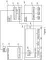
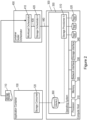
- Figures 1 and 2 illustrate existing systems comprising such a storage provisioning node 510, which provides storage volumes to workloads.
- a compute node 300 often comprises processing circuitry (e.g. a processor) 310, a memory 320, a network interface 330 and optionally a storage interface 340.
- the workloads running on the compute node 300 share an operating system (OS) 350.
- OS operating system
- storage is provided by a storage backend 500, which is attached to the compute node 300 through a network using the network interface 330.
- the storage backend 500 comprises the storage provisioning node 510.
- storage is directly attached by means of the storage interface 340 to the compute node 300.
- the OS 350 of the compute node 300 comprises the storage provisioning node 510.
- all data center resources are allocated to workloads by an orchestrator (e.g. a container cluster orchestrator) 400.
- the orchestrator 400 comprises a workload orchestrator 410 that orchestrates compute resources.
- the orchestrator 400 also comprises a storage orchestrator 420 that orchestrates storage resources.
- the workload orchestrator 410 and the storage orchestrator 420 can communicate via an interface 430.
- workloads run within an application node (e.g. an application container or workload container) 100.
- application nodes e.g. application containers or workload containers
- Each of these application nodes 100 can request one or more storage volumes 360.
- the storage needs of a storage consumer (e.g. a user or an application) 120 that requires data storage are expressed within a request 110 that is processed by the orchestrator 400 at the time of application node deployment.
- the workload orchestrator 410 uses the storage orchestrator 420 to request storage from the storage provisioning node 510.
- the storage provisioning node 510 maintains a pool of storage devices 520, reserves the requested amount of storage and makes it available to the compute node 300.
- the storage orchestrator 420 uses an interface 440 to the OS 350 on the compute node 300 to create a storage volume 360 that is accessible to the storage consumer 120.
- Figure 3 is a signalling (or call flow) diagram illustrating an exchange of signals in an existing system, such as those illustrated in Figures 1 and 2 .
- the existing system illustrated in Figure 3 comprises the application node 100, the OS 350 of the compute node 300, the storage provisioning node 510, the orchestrator 400, and an application management node 600.
- the application management node 600 transmits a deployment request towards the orchestrator 400.
- the deployment request is a request to deploy an application node (e.g. an application container or workload container) 100.
- the orchestrator 400 transmits a request for storage towards the storage provisioning node 510.
- the storage provisioning node 510 transmits a request towards the OS 350 for the OS 350 to mount the storage volume 360.
- the OS 350 mounts the storage volume 360 to the compute node 300 and thus the storage volume 360 becomes available to the application node 100 (or, more specifically, the storage consumer 120).
- the request for storage may be acknowledged by the storage provisioning node 510 to the orchestrator 400.
- the orchestrator 400 transmits a request towards the OS 350, which is a request for the OS 350 to create the application node 100. Then, the OS 350 allocates central processing unit (CPU) time for the application node 100 to run. Thus, as illustrated by arrow 712 of Figure 3 , the OS 350 transmits a request towards the application node 100, which is a request for the application node 100 to start. At block 714 of Figure 3 , the application node 100 uses (or consumes) the storage volume 360.
- CPU central processing unit
- WO2008037741 relates to encryption management for volumes in storage pools, wherein an encryption status indicates whether encryption is enabled for a pool or volume;
- US2008080706 relates to disk-based storage comprising encrypted and unencrypted data storage units
- US2010211802 relates to a computing device accessing a storage volume encrypted using a technique unsupported by its operating system.
- the claimed invention relates to a method, a node, a method, a node, a method, a node, a system and a computer program as defined in claims 1, 4, 6, 8, 10, 15, 17 and 18, respectively.
- Various embodiments are defined in the dependent claims.
- a method for provisioning storage in a system is performed by an encryption node.
- the encryption node is associated with an application node and the application node is configured to run at least part of one or more applications.
- the method comprises, in response to an unencrypted storage volume becoming available to the encryption node from a storage provisioning node of the system, generating an encrypted storage volume from the unencrypted storage volume and initiating provisioning of the encrypted storage volume to make the encrypted storage volume available at a compute node of the system for use by the application node.
- the method supports volume level encryption.
- This encryption on a volume level allows finer granularity for the creation of security domains, for example, compared with storage encryption performed on device level. It allows every volume to be encrypted with a different key.
- the method allows security requirements on storage encryption to be satisfied without being dependent on encryption functionality provided by cloud systems. It is possible to provide encrypted storage volumes to application nodes even if a data center does not support such functionality.
- the method also avoids the need for software to be created (or modified) and implemented for every storage provisioning node that is added to the system infrastructure and/or for every new application release, which provides easier development and integration.
- the encrypted storage that is provided by way of the method can be used by any application node. It requires only a minimal additional software footprint and no extra storage footprint. There is also no impact on application nodes if the storage provisioning node is replaced with a different one. Moreover, different to encryption of data at rest on an infrastructure level, it allows the creation of different security domains on a per storage volume basis, e.g. by encrypting volumes with individual keys.
- the method may be performed prior to initiation of the application node. This can be particularly advantageous in a system where the addition of volumes to already deployed nodes (e.g. containers) is not supported. Furthermore, where an application node (e.g. container) assumes a storage volume to be available from the start, error conditions (and even fatal error conditions) that the application node may otherwise run into can be avoided.
- an application node e.g. container
- error conditions and even fatal error conditions
- initiating provisioning of the encrypted storage volume to make the encrypted storage volume available at the compute node for use by the application node may comprise initiating mounting of the encrypted storage volume to the compute node to make the encrypted storage volume available at the compute node for use by the application node.
- initiating mounting of the encrypted storage volume to the compute node to make the encrypted storage volume available at the compute node for use by the application node may comprise initiating mounting of the encrypted storage volume to the compute node to make the encrypted storage volume available at the compute node for use by the application node.
- initiating mounting of the encrypted storage volume to the compute node may comprise initiating mounting of the encrypted storage volume to a directory tree of the compute node. This can be particularly advantageous when the encrypted storage volume needs to be made available to multiple application nodes on the same compute node. In particular, having a separate mount point simplifies the adding and removing of application node specific mount points.
- initiating provisioning of the encrypted storage volume to make the encrypted storage volume available at the compute node for use by the application node may comprise initiating generation of a hostpath volume for making the encrypted storage volume available to the application node.
- the encrypted storage volume may be generated by applying an encrypted layer to the unencrypted storage volume.
- the encrypted layer may be an encrypted file system layer.
- an encryption node comprising processing circuitry configured to operate in accordance with the method described earlier in respect of the encryption node.
- the encryption node thus provides the advantages discussed earlier in respect of the method performed by the encryption node.
- the encryption node comprises at least one memory for storing instructions which, when executed by the processing circuitry, cause the encryption node to operate in accordance with the method described earlier in respect of the encryption node.
- this method is performed by a storage provisioning node in the system.
- the method comprises, in response to a first request for an unencrypted storage volume, initiating provisioning of the unencrypted storage volume to make the unencrypted storage volume available at a compute node of the system to an encryption node for the encryption node to use in the generation of an encrypted storage volume to be made available at the compute node for use by an application node.
- the application node is configured to run at least part of one or more applications and the encryption node is associated with the application node.
- the method supports volume level encryption.
- This encryption on a volume level allows finer granularity for the creation of security domains, for example, compared with storage encryption performed on device level. It allows every volume to be encrypted with a different key.
- the method allows security requirements on storage encryption to be satisfied without being dependent on encryption functionality provided by cloud systems. It is possible to provide encrypted storage volumes to application nodes even if a data center does not support such functionality.
- the method also avoids the need for software to be created (or modified) and implemented for every storage provisioning node that is added to the system infrastructure and/or for every new application release, which provides easier development and integration.
- the encrypted storage that is provided by way of the method can be used by any application node. It requires only a minimal additional software footprint and no extra storage footprint. There is also no impact on application nodes if the storage provisioning node is replaced with a different one. Moreover, different to encryption of data at rest on an infrastructure level, it allows the creation of different security domains on a per storage volume basis, e.g. by encrypting volumes with individual keys.
- the method may be performed prior to initiation of the application node. This can be particularly advantageous in a system where the addition of volumes to already deployed nodes (e.g. containers) is not supported. Furthermore, where an application node (e.g. container) assumes a storage volume to be available from the start, error conditions (and even fatal error conditions) that the application node may otherwise run into can be avoided.
- an application node e.g. container
- error conditions and even fatal error conditions
- initiating provisioning of the unencrypted storage volume to make the unencrypted storage volume available at the compute node to the encryption node may comprise initiating mounting of the unencrypted storage volume to the compute node to make the unencrypted storage volume available to the encryption node.
- initiating mounting of the unencrypted storage volume to the compute node to make the unencrypted storage volume available to the encryption node may comprise initiating mounting of the unencrypted storage volume to the compute node to make the unencrypted storage volume available to the encryption node.
- the compute node may be separate to the storage provisioning node. In this way, performance dependencies between the storage and application nodes running on compute nodes can be avoided.
- the compute node may comprise the storage provisioning node. This allows easier scaling of the storage solution and reduces hardware cost by avoiding dedicated storage hardware and instead allows to make use of only one type of compute node (e.g. server) for the application nodes and storage.
- a storage provisioning node comprising processing circuitry configured to operate in accordance with the method described earlier in respect of the storage provisioning node.
- the storage provisioning node thus provides the advantages discussed earlier in respect of the method performed by the storage provisioning node.
- the storage provisioning node comprises at least one memory for storing instructions which, when executed by the processing circuitry, cause the storage provisioning node to operate in accordance with the method described earlier in respect of the storage provisioning node.
- Another method for provisioning storage in a system is performed by a compute node of the system.
- the method comprises provisioning a requested unencrypted storage volume to make the requested unencrypted storage volume available at the compute node to an encryption node for the encryption node to use in the generation of an encrypted storage volume and provisioning the encrypted storage volume generated by the encryption node to make the encrypted storage volume available at the compute node for use by an application node.
- the application node is configured to run at least part of one or more applications and the encryption node is associated with the application node.
- the method supports volume level encryption.
- This encryption on a volume level allows finer granularity for the creation of security domains, for example, compared with storage encryption performed on device level. It allows every volume to be encrypted with a different key.
- the method allows security requirements on storage encryption to be satisfied without being dependent on encryption functionality provided by cloud systems. It is possible to provide encrypted storage volumes to application nodes even if a data center does not support such functionality.
- the method also avoids the need for software to be created (or modified) and implemented for every storage provisioning node that is added to the system infrastructure and/or for every new application release, which provides easier development and integration.
- the encrypted storage that is provided by way of the method can be used by any application node. It requires only a minimal additional software footprint and no extra storage footprint. There is also no impact on application nodes if the storage provisioning node is replaced with a different one. Moreover, different to encryption of data at rest on an infrastructure level, it allows the creation of different security domains on a per storage volume basis, e.g. by encrypting volumes with individual keys.
- the method may be performed prior to initiation of the application node. This can be particularly advantageous in a system where the addition of volumes to already deployed nodes (e.g. containers) is not supported. Furthermore, where an application node (e.g. container) assumes a storage volume to be available from the start, error conditions (and even fatal error conditions) that the application node may otherwise run into can be avoided.
- an application node e.g. container
- error conditions and even fatal error conditions
- provisioning the encrypted storage volume to make the encrypted storage volume available at the compute node may comprise generating a hostpath volume for making the encrypted storage volume available to the application node.
- provisioning the requested unencrypted storage volume to make the requested unencrypted storage volume available at the compute node to the encryption node may comprise mounting the requested unencrypted storage volume to the compute node to make the requested unencrypted storage volume available to the encryption node and/or provisioning the encrypted storage volume to make the encrypted storage volume available at the compute node for use by the application node may comprise mounting the encrypted storage volume to the compute node to make the encrypted storage volume available at the compute node for use by the application node.
- mounting the requested unencrypted storage volume to the compute node may comprise mounting the requested unencrypted storage volume to a directory tree of the compute node and/or mounting the encrypted storage volume to the compute node may comprise mounting the encrypted storage volume to the directory tree of the compute node.
- the method may comprise unmounting the unencrypted storage volume from the compute node and/or unmounting the encrypted storage volume from the compute node. This can be particularly advantageous when the application node that consumes the encrypted volume is terminated on the compute node, for example, due to decommissioning of the application node or an orchestrator deciding to run the application node on a different compute node.
- the method may comprise, in response to termination of an application node that uses the encrypted storage volume, removing a configuration related to the encrypted storage volume from the compute node.
- the compute node may be separate to a storage provisioning node of the system. In this way, performance dependencies between the storage and application nodes running on compute nodes can be avoided.
- the compute node may comprise a storage provisioning node of the system. This allows easier scaling of the storage solution and reduces hardware cost by avoiding dedicated storage hardware and instead allows to make use of only one type of compute node (e.g. server) for the application nodes and storage.
- a compute node comprising processing circuitry configured to operate in accordance with the method described earlier in respect of the compute node.
- the compute node thus provides the advantages discussed earlier in respect of the method performed by the compute node.
- the compute node comprises at least one memory for storing instructions which, when executed by the processing circuitry, cause the compute node to operate in accordance with the method described earlier in respect of the compute node.
- a system comprising one or more encryption nodes as described earlier, one or more storage provisioning nodes as described earlier and/or one or more compute nodes as described earlier.
- the system thus provides the advantages discussed earlier in respect of the method performed by the encryption node, storage provisioning node and/or compute node.
- a computer program comprising instructions which, when executed by processing circuitry, cause the processing circuitry to perform the method described earlier in respect of the encryption node, storage provisioning node and/or compute node.
- the computer program thus provides the advantages discussed earlier in respect of the method performed by the encryption node, storage provisioning node and/or compute node.
- a computer program product embodied on a non-transitory machine-readable medium, comprising instructions which are executable by processing circuitry to cause the processing circuitry to perform the method described earlier in respect of the encryption node, storage provisioning node and/or compute node.
- the computer program product thus provides the advantages discussed earlier in respect of the method performed by the encryption node, storage provisioning node and/or compute node.
- a storage volume can be any unit of storage.
- the storage volumes referred to herein can be configured to store data, information, objects, etc.
- a storage volume may be a file system.
- the technique described herein is implemented by an encryption node, a storage provisioning node and a compute node.
- the technique described herein may, for example, be applied to data centers, such as data centers that use container technology. These data centers that use container technology may also be referred to as cloud data centers.
- workloads may be distributed over multiple containers.
- the multiple containers can be scheduled to execute on a plurality of compute nodes (or hosts).
- An agent of a storage provisioner may be present on each compute node.
- the agent may communicate with an operating system of the compute node.
- the system described herein for which storage is provisioned may comprise a plurality of compute nodes that are configured in the manner described herein.
- a plurality of compute nodes may also be referred to as a cluster.
- provisioning storage or storage provisioning can be defined as the process of assigning storage and making that storage available to an application node, e.g. for read and/or write operations.
- FIG. 4 illustrates an encryption node 200 in accordance with an embodiment.
- the encryption node 200 is for provisioning storage in a system.
- the encryption node 200 is associated with an application node.
- the application node 200 is configured to run at least part of one or more applications.
- the encryption node 200 may, for example, be a physical machine (e.g. a server) or a virtual machine (VM).
- VM virtual machine
- the encryption node 200 comprises processing circuitry (or logic) 202.
- the processing circuitry 202 controls the operation of the encryption node 200 and can implement the method described herein in respect of the encryption node 200.
- the processing circuitry 202 can be configured or programmed to control the encryption node 200 in the manner described herein.
- the processing circuitry 202 can comprise one or more hardware components, such as one or more processors, one or more processing units, one or more multi-core processors, and/or one or more modules.
- each of the one or more hardware components can be configured to perform, or is for performing, individual or multiple steps of the method described herein in respect of the encryption node 200.
- the processing circuitry 202 can be configured to run software to perform the method described herein in respect of the encryption node 200.
- the software may be containerised according to some embodiments.
- the processing circuitry 202 may be configured to run a container (e.g. an init container) to perform the method described herein in respect of the encryption node 200. This container may run in privileged mode.
- the processing circuitry 202 of the encryption node 200 is configured to, in response to an unencrypted storage volume becoming available to the encryption node from a storage provisioning node of the system, generate an encrypted storage volume from the unencrypted storage volume and initiate provisioning of the encrypted storage volume to make the encrypted storage volume available at a compute node of the system for use by the application node.
- the encryption node 200 may optionally comprise a memory 204.
- the memory 204 of the encryption node 200 can comprise a volatile memory or a non-volatile memory.
- the memory 204 of the encryption node 200 may comprise a non-transitory media. Examples of the memory 204 of the encryption node 200 include, but are not limited to, a random access memory (RAM), a read only memory (ROM), a mass storage media such as a hard disk, a removable storage media such as a compact disk (CD) or a digital video disk (DVD), and/or any other memory.
- RAM random access memory
- ROM read only memory
- CD compact disk
- DVD digital video disk
- the processing circuitry 202 of the encryption node 200 can be connected to the memory 204 of the encryption node 200.
- the memory 204 of the encryption node 200 may be for storing program code or instructions which, when executed by the processing circuitry 202 of the encryption node 200, cause the encryption node 200 to operate in the manner described herein in respect of the encryption node 200.
- the memory 204 of the encryption node 200 may be configured to store program code or instructions that can be executed by the processing circuitry 202 of the encryption node 200 to cause the encryption node 200 to operate in accordance with the method described herein in respect of the encryption node 200.
- the memory 204 of the encryption node 200 can be configured to store any information, data, messages, requests, responses, indications, notifications, signals, or similar, that are described herein.
- the processing circuitry 202 of the encryption node 200 may be configured to control the memory 204 of the encryption node 200 to store information, data, messages, requests, responses, indications, notifications, signals, or similar, that are described herein.
- the encryption node 200 may optionally comprise a communications interface 206.
- the communications interface 206 of the encryption node 200 can be connected to the processing circuitry 202 of the encryption node 200 and/or the memory 204 of encryption node 200.
- the communications interface 206 of the encryption node 200 may be operable to allow the processing circuitry 202 of the encryption node 200 to communicate with the memory 204 of the encryption node 200 and/or vice versa.
- the communications interface 206 of the encryption node 200 may be operable to allow the processing circuitry 202 of the encryption node 200 to communicate with the storage provisioning node, compute node and/or any other node.
- the communications interface 206 of the encryption node 200 can be configured to transmit and/or receive information, data, messages, requests, responses, indications, notifications, signals, or similar, that are described herein.
- the processing circuitry 202 of the encryption node 200 may be configured to control the communications interface 206 of the encryption node 200 to transmit and/or receive information, data, messages, requests, responses, indications, notifications, signals, or similar, that are described herein.
- the encryption node 200 is illustrated in Figure 4 as comprising a single memory 204, it will be appreciated that the encryption node 200 may comprise at least one memory (i.e. a single memory or a plurality of memories) 204 that operate in the manner described herein.
- the encryption node 200 is illustrated in Figure 4 as comprising a single communications interface 206, it will be appreciated that the encryption node 200 may comprise at least one communications interface (i.e. a single communications interface or a plurality of communications interface) 206 that operate in the manner described herein.
- Figure 4 only shows the components required to illustrate an embodiment of the encryption node 200 and, in practical implementations, the encryption node 200 may comprise additional or alternative components to those shown.
- the hardware e.g. processing circuitry 202, memory 204, and/or communications interface 206 that can implement the method described herein in respect of the encryption node 200 may be the same hardware as that which implements the method performed by the application node that is associated with the encryption node 200.
- the same hardware e.g. processing circuitry, memory, and/or communications interface
- the same hardware e.g. processing circuitry, memory, and/or communications interface
- the same hardware e.g. processing circuitry, memory, and/or communications interface
- the same hardware that is configured to run at least part of one or more applications may also be configured to implement the method described herein in respect of the encryption node 200.
- the hardware that can implement the method described herein in respect of the encryption node 200 and/or the hardware that can implement the method described herein in respect of the application node may be the same hardware as that which implements the method performed by a compute node (e.g. of a cluster of compute nodes), such as the compute node described herein.
- Figure 5 is a flowchart illustrating a method performed by an encryption node 200 in accordance with an embodiment.
- the method is for provisioning storage in a system.
- the encryption node 200 described earlier with reference to Figure 4 is configured to operate in accordance with the method of Figure 5 .
- the method can be performed by or under the control of the processing circuitry 202 of the encryption node 200.
- an encrypted storage volume is generated from the unencrypted storage volume. More specifically, the processing circuitry 202 of the encryption node 200 generates the encrypted storage volume from the unencrypted storage volume. In some embodiments, the generation of the encrypted storage volume may be performed in response to a request for an unencrypted storage volume, e.g. at deployment of the application node.
- the encrypted storage volume may be generated by applying an encrypted layer to the unencrypted storage volume. More specifically, in some embodiments, the processing circuitry 202 of the encryption node 200 can be configured to apply the encrypted layer to the unencrypted storage volume. In some embodiments, the application of the encrypted layer may be chosen when the unencrypted storage volume is provided with an unencrypted file system. In some embodiments, the encrypted layer may be an encrypted file system layer. For example, an encrypted file system may be deployed as a layer on top of the unencrypted storage volume. In some embodiments, an encrypted file system layer may be chosen when the unencrypted storage volume is an unencrypted raw block storage (i.e.
- the unencrypted storage volume may itself be an unencrypted file system.
- the encrypted layer may be provided by the encryption node 200. In other embodiments, another node may provide the encrypted layer.
- the processing circuitry 202 of the encryption node 200 may generate a file and use a device mapper functionality (e.g. where a file from the unencrypted storage volume is exposed as an encrypted storage device, which is formatted with another file system) to create an encrypted storage device as the encrypted storage volume referred to herein.
- the processing circuitry 202 of the encryption node 200 may first format the device with a filesystem and then use this filesystem as the encrypted storage volume referred to herein.
- the processing circuitry 202 of the encryption node 200 may format a (raw) block storage device with a filesystem that supports encryption and use this filesystem as the encrypted storage volume referred to herein.
- provisioning of the encrypted storage volume is initiated to make the encrypted storage volume available at a compute node of the system for use by the application node. More specifically, in some embodiments, the processing circuitry 202 of the encryption node 200 initiates the provisioning of the encrypted storage volume.
- the processing circuitry 202 of the encryption node 200 may be configured to instruct (e.g. an operating system of) the compute node 300 to make the encrypted storage volume available for use by the application node.
- the processing circuitry 202 of the encryption node 200 may be configured to initiate transmission of (e.g. itself transmit or cause another node to transmit) the instruction towards (e.g. an operating system of) the compute node.
- the instruction may be for the compute node 300 to publish the encrypted storage volume for use by the application node.
- initiating provisioning of the encrypted storage volume at block 22 of Figure 5 to make the encrypted storage volume available at the compute node for use by the application node may comprise initiating mounting of the encrypted storage volume to the compute node to make the encrypted storage volume available at the compute node for use by the application node.
- initiating mounting of the encrypted storage volume to the compute node may comprise initiating mounting of the encrypted storage volume to a directory tree of the compute node.
- mounting of the encrypted storage volume to the compute node is only one example of the manner in which the encrypted storage volume can be made available at the compute node for use by the application node and that other examples are also possible.
- the encrypted storage volume can be made available at the compute node for use by the application node through other interfaces, such as a hypertext transfer protocol (HTTP) interface. This can be particularly useful for object storage.
- HTTP hypertext transfer protocol
- initiating provisioning of the encrypted storage volume at block 22 of Figure 5 to make the encrypted storage volume available at the compute node for use by the application node may comprise initiating generation of a hostpath volume for making the encrypted storage volume available to the application node.
- the application node may have a hostpath volume configured. In some embodiments, this may trigger an orchestrator to allocate a path within a directory tree of a host file system that is accessible to the application node.
- FIG. 6 illustrates a storage provisioning node 510 in accordance with an embodiment.
- the storage provisioning node 510 is for provisioning storage in a system.
- the storage provisioning node 510 may, for example, be a physical machine (e.g. a server) or a virtual machine (VM).
- a physical machine e.g. a server
- VM virtual machine
- the storage provisioning node 510 comprises processing circuitry (or logic) 502.
- the processing circuitry 502 controls the operation of the storage provisioning node 510 and can implement the method described herein in respect of the storage provisioning node 510.
- the processing circuitry 502 can be configured or programmed to control the storage provisioning node 510 in the manner described herein.
- the processing circuitry 502 can comprise one or more hardware components, such as one or more processors, one or more processing units, one or more multi-core processors, and/or one or more modules.
- each of the one or more hardware components can be configured to perform, or is for performing, individual or multiple steps of the method described herein in respect of the storage provisioning node 510.
- the processing circuitry 502 can be configured to run software to perform the method described herein in respect of the storage provisioning node 510.
- the software may be containerised according to some embodiments.
- the processing circuitry 502 may be configured to run a container to perform the method described herein in respect of the storage provisioning node 510.
- the processing circuitry 502 of the storage provisioning node 510 is configured to, in response to a first request for an unencrypted storage volume, initiate provisioning of the unencrypted storage volume to make the unencrypted storage volume available at a compute node of the system to an encryption node 200 for the encryption node 200 to use in the generation of an encrypted storage volume to be made available at the compute node for use by an application node.
- the application node is configured to run at least part of one or more applications and the encryption node 200 is associated with the application node.
- the storage provisioning node 510 may optionally comprise a memory 520.
- the memory 520 of the storage provisioning node 510 can comprise a volatile memory or a non-volatile memory.
- the memory 520 of the storage provisioning node 510 may comprise a non-transitory media. Examples of the memory 520 of the storage provisioning node 510 include, but are not limited to, a random access memory (RAM), a read only memory (ROM), a mass storage media such as a hard disk, a removable storage media such as a compact disk (CD) or a digital video disk (DVD), and/or any other memory.
- the memory 520 of the storage provisioning node 510 may comprise one or more storage devices, e.g. a pool of storage devices.
- the processing circuitry 502 of the storage provisioning node 510 can be connected to the memory 520 of the storage provisioning node 510.
- the memory 520 of the storage provisioning node 510 may be for storing program code or instructions which, when executed by the processing circuitry 502 of the storage provisioning node 510, cause the storage provisioning node 510 to operate in the manner described herein in respect of the storage provisioning node 510.
- the memory 520 of the storage provisioning node 510 may be configured to store program code or instructions that can be executed by the processing circuitry 502 of the storage provisioning node 510 to cause the storage provisioning node 510 to operate in accordance with the method described herein in respect of the storage provisioning node 510.
- the memory 520 of the storage provisioning node 510 can be configured to store any information, data, messages, requests, responses, indications, notifications, signals, or similar, that are described herein.
- the processing circuitry 502 of the storage provisioning node 510 may be configured to control the memory 520 of the storage provisioning node 510 to store information, data, messages, requests, responses, indications, notifications, signals, or similar, that are described herein.
- the storage provisioning node 510 may optionally comprise a communications interface 506.
- the communications interface 506 of the storage provisioning node 510 can be connected to the processing circuitry 502 of the storage provisioning node 510 and/or the memory 520 of storage provisioning node 510.
- the communications interface 506 of the storage provisioning node 510 may be operable to allow the processing circuitry 502 of the storage provisioning node 510 to communicate with the memory 520 of the storage provisioning node 510 and/or vice versa.
- the communications interface 506 of the storage provisioning node 510 may be operable to allow the processing circuitry 502 of the storage provisioning node 510 to communicate with the encryption node, compute node and/or any other node.
- the communications interface 506 of the storage provisioning node 510 can be configured to transmit and/or receive information, data, messages, requests, responses, indications, notifications, signals, or similar, that are described herein.
- the processing circuitry 502 of the storage provisioning node 510 may be configured to control the communications interface 506 of the storage provisioning node 510 to transmit and/or receive information, data, messages, requests, responses, indications, notifications, signals, or similar, that are described herein.
- the storage provisioning node 510 is illustrated in Figure 6 as comprising a single memory 520, it will be appreciated that the storage provisioning node 510 may comprise at least one memory (i.e. a single memory or a plurality of memories) 520 that operate in the manner described herein.
- the storage provisioning node 510 is illustrated in Figure 6 as comprising a single communications interface 506, it will be appreciated that the storage provisioning node 510 may comprise at least one communications interface (i.e. a single communications interface or a plurality of communications interface) 506 that operate in the manner described herein.
- Figure 6 only shows the components required to illustrate an embodiment of the storage provisioning node 510 and, in practical implementations, the storage provisioning node 510 may comprise additional or alternative components to those shown.
- the hardware e.g. processing circuitry 502, memory 520, and/or communications interface 506 that can implement the method described herein in respect of the storage provisioning node 510 may be the same hardware as that which implements the method performed by a compute node (e.g. of a cluster of compute nodes), such as the compute node described herein.
- the storage provisioning node 510 may be software that the hardware (e.g. processing circuitry) of the compute node can run to implement the method described herein in respect of the storage provisioning node 510.
- the hardware e.g.
- processing circuitry 502, memory 520, and/or communications interface 506) that can implement the method described herein in respect of the storage provisioning node 510 may be the hardware of a storage backend node that comprises the storage provisioning node 510.
- the storage provisioning node 510 may be software that the hardware (e.g. processing circuitry) of the storage backend node can run to implement the method described herein in respect of the storage provisioning node 510.
- Figure 7 is a flowchart illustrating a method performed by a storage provisioning node 510 in accordance with an embodiment.
- the method is for provisioning storage in a system.
- the storage provisioning node 510 described earlier with reference to Figure 6 is configured to operate in accordance with the method of Figure 7 .
- the method can be performed by or under the control of the processing circuitry 502 of the storage provisioning node 510.
- provisioning of the unencrypted storage volume is initiated to make the unencrypted storage volume available at a compute node of the system to an encryption node 200 for the encryption node 200 to use in the generation of an encrypted storage volume to be made available at the compute node for use by an application node.
- the processing circuitry 502 of the storage provisioning node 510 initiates the provisioning of the unencrypted storage volume.
- the processing circuitry 502 of the storage provisioning node 510 may be configured to instruct (e.g. an operating system of) the compute node to make the unencrypted storage volume available to the encryption node 200.
- the processing circuitry 502 of the storage provisioning node 510 may be configured to initiate transmission of (e.g. itself transmit or cause another node to transmit) the instruction towards (e.g. an operating system of) the compute node.
- the instruction may be for the compute node to publish the unencrypted storage volume system to the encryption node 200.
- the application node is configured to run at least part of one or more applications and the encryption node 200 is associated with the application node.
- initiating provisioning of the unencrypted storage volume to make the unencrypted storage volume available at the compute node to the encryption node 200 may comprise initiating mounting of the unencrypted storage volume to the compute node to make the unencrypted storage volume available to the encryption node 200.
- mounting of the unencrypted storage volume to the compute node is only one example of the manner in which the unencrypted storage volume can be made available at the compute node to the encryption node 200 and that other examples are also possible.
- the unencrypted storage volume can be made available at the compute node to the encryption node 200 through other interfaces, such as a hypertext transfer protocol (HTTP) interface. This can be particularly useful for object storage.
- HTTP hypertext transfer protocol
- the compute node may be separate to the storage provisioning node 510.
- the storage provisioning node 510 (or, in some embodiments, the storage backend 500 that comprises the storage provisioning node 510) may be an entity that is separate to the compute node described herein, with its own dedicated software and/or hardware.
- the compute node may comprise the storage provisioning node 510.
- the method described herein in respect of the storage provisioning node 510 may be running as (e.g. containerised) software on the compute node described herein.
- the compute node described herein may at the same time be running (e.g. containerised) application software.
- the compute node described herein may be exclusively used for storage. This may be referred to as "software defined storage”.
- the method described herein in respect of the storage provisioning node 510 may be running as (e.g. containerised) software on one or more (or each) of the plurality of compute nodes.
- the method may comprise initiating unprovisioning of the unencrypted storage volume to cease making the unencrypted storage volume available at the compute node.
- the processing circuitry 502 of the storage provisioning node 510 may be configured to initiate the unprovisioning of the unencrypted storage volume.
- the processing circuitry 502 of the storage provisioning node 510 may be configured to instruct (e.g. an operating system of) the compute node to cease making the unencrypted storage volume available.
- the processing circuitry 502 of the storage provisioning node 510 may be configured to initiate transmission of (e.g. itself transmit or cause another node to transmit) the instruction towards (e.g. an operating system of) the compute node.
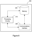
- Figure 8 illustrates a compute node 300 in accordance with an embodiment.
- the compute node 300 is for provisioning storage in a system.
- the compute node 300 may also be referred to herein as a compute host.
- the compute node 300 may, for example, be a physical machine (e.g. a server) or a virtual machine (VM).
- the compute node 300 can be configured to run (e.g. the software for) the application node referred to herein.
- the compute node 300 comprises processing circuitry (or logic) 310.
- the processing circuitry 310 controls the operation of the compute node 300 and can implement the method described herein in respect of the compute node 300.
- the processing circuitry 310 can be configured or programmed to control the compute node 300 in the manner described herein.
- the processing circuitry 310 can comprise one or more hardware components, such as one or more processors, one or more processing units, one or more multi-core processors, and/or one or more modules.
- each of the one or more hardware components can be configured to perform, or is for performing, individual or multiple steps of the method described herein in respect of the compute node 300.
- the processing circuitry 310 can be configured to run software to perform the method described herein in respect of the compute node 300.
- the software may be containerised according to some embodiments.
- the processing circuitry 310 may be configured to run a container to perform the method described herein in respect of the compute node 300.
- the processing circuitry 310 of the compute node 300 is configured to provision a requested unencrypted storage volume to make the requested unencrypted storage volume available at the compute node 300 to an encryption node 200 for the encryption node 200 to use in the generation of an encrypted storage volume.
- the processing circuitry 310 of the compute node 300 is also configured to provision the encrypted storage volume generated by the encryption node 200 to make the encrypted storage volume available at the compute node 300 for use by an application node.
- the application node is configured to run at least part of one or more applications and the encryption node 200 is associated with the application node.
- the compute node 300 may optionally comprise a memory 320.
- the memory 320 of the compute node 300 can comprise a volatile memory or a non-volatile memory.
- the memory 320 of the compute node 300 may comprise a non-transitory media. Examples of the memory 320 of the compute node 300 include, but are not limited to, a random access memory (RAM), a read only memory (ROM), a mass storage media such as a hard disk, a removable storage media such as a compact disk (CD) or a digital video disk (DVD), and/or any other memory.
- RAM random access memory
- ROM read only memory
- CD compact disk
- DVD digital video disk
- the processing circuitry 310 of the compute node 300 can be connected to the memory 320 of the compute node 300.
- the memory 320 of the compute node 300 may be for storing program code or instructions which, when executed by the processing circuitry 310 of the compute node 300, cause the compute node 300 to operate in the manner described herein in respect of the compute node 300.
- the memory 320 of the compute node 300 may be configured to store program code or instructions that can be executed by the processing circuitry 310 of the compute node 300 to cause the compute node 300 to operate in accordance with the method described herein in respect of the compute node 300.
- the memory 320 of the compute node 300 can be configured to store any information, data, messages, requests, responses, indications, notifications, signals, or similar, that are described herein.
- the processing circuitry 31 0 of the compute node 300 may be configured to control the memory 320 of the compute node 300 to store information, data, messages, requests, responses, indications, notifications, signals, or similar, that are described herein.
- the compute node 300 may optionally comprise a communications interface 306, e.g. a network interface and/or a storage interface.
- the communications interface 306 of the compute node 300 can be connected to the processing circuitry 310 of the compute node 300 and/or the memory 320 of compute node 300.
- the communications interface 306 of the compute node 300 may be operable to allow the processing circuitry 310 of the compute node 300 to communicate with the memory 320 of the compute node 300 and/or vice versa.
- the communications interface 306 of the compute node 300 may be operable to allow the processing circuitry 310 of the compute node 300 to communicate with the storage provisioning node, encryption node and/or any other node.
- the communications interface 306 of the compute node 300 can be configured to transmit and/or receive information, data, messages, requests, responses, indications, notifications, signals, or similar, that are described herein.
- the processing circuitry 310 of the compute node 300 may be configured to control the communications interface 306 of the compute node 300 to transmit and/or receive information, data, messages, requests, responses, indications, notifications, signals, or similar, that are described herein.
- the compute node 300 is illustrated in Figure 8 as comprising a single memory 320, it will be appreciated that the compute node 300 may comprise at least one memory (i.e. a single memory or a plurality of memories) 320 that operate in the manner described herein.
- the compute node 300 is illustrated in Figure 8 as comprising a single communications interface 306, it will be appreciated that the compute node 300 may comprise at least one communications interface (i.e. a single communications interface or a plurality of communications interface) 306 that operate in the manner described herein.
- Figure 8 only shows the components required to illustrate an embodiment of the compute node 300 and, in practical implementations, the compute node 300 may comprise additional or alternative components to those shown.
- the hardware e.g. processing circuitry 310, memory 320, and/or communications interface 306 that can implement the method described herein in respect of the compute node 300 may also be used to implement the method described herein in respect of the encryption node 200 and/or the method described herein in respect of the application node.
- the hardware e.g. processing circuitry 310, memory 320, and/or communications interface 306 that can implement the method described herein in respect of the compute node 300 may also be used to implement the method performed by the storage provisioning node 510.
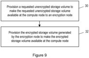
- Figure 9 is a flowchart illustrating a method performed by a compute node 300 in accordance with an embodiment.
- the method is for provisioning storage in a system.
- the compute node 300 described earlier with reference to Figure 8 is configured to operate in accordance with the method of Figure 9 .
- the method can be performed by or under the control of the processing circuitry 310 of the compute node 300.
- a requested unencrypted storage volume is provisioned to make the requested unencrypted storage volume available at the compute node 300 to an encryption node 200 for the encryption node 200 to use in the generation of an encrypted storage volume. More specifically, the processing circuitry 310 of the compute node 300 provisions the requested unencrypted storage volume.
- provisioning the requested unencrypted storage volume at block 30 of Figure 9 to make the requested unencrypted storage volume available at the compute node 300 to the encryption node 200 may comprise mounting the requested unencrypted storage volume to the compute node 300 to make the requested unencrypted storage volume available to the encryption node 200.
- mounting the requested unencrypted storage volume to the compute node 300 may comprise mounting the requested unencrypted storage volume to a directory tree of the compute node 300.
- the unencrypted storage volume can be made available at the compute node to the encryption node 200 and that other examples are also possible.
- the unencrypted storage volume can be made available at the compute node to the encryption node 200 through other interfaces, such as a hypertext transfer protocol (HTTP) interface. This can be particularly useful for object storage.
- HTTP hypertext transfer protocol
- the encrypted storage volume generated by the encryption node 200 is provisioned to make the encrypted storage volume available at the compute node 300 for use by an application node. More specifically, the processing circuitry 310 of the compute node 300 provisions the encrypted storage volume.
- provisioning the encrypted storage volume at block 32 of Figure 9 to make the encrypted storage volume available at the compute node 300 for use by the application node may comprise mounting the encrypted storage volume to the compute node 300 to make the encrypted storage volume available at the compute node 300 for use by the application node.
- mounting the encrypted storage volume to the compute node 300 may comprise mounting the encrypted storage volume to the directory tree of the compute node 300.
- mounting of the encrypted storage volume to the compute node is only one example of the manner in which the encrypted storage volume can be made available at the compute node for use by the application node and that other examples are also possible.
- the encrypted storage volume can be made available at the compute node for use by the application node through other interfaces, such as a hypertext transfer protocol (HTTP) interface. This can be particularly useful for object storage.
- HTTP hypertext transfer protocol
- provisioning the encrypted storage volume at block 32 of Figure 9 to make the encrypted storage volume available at the compute node 300 may comprise generating a hostpath volume for making the encrypted storage volume available to the application node. In some embodiments, this may trigger an orchestrator to allocate a path within a directory tree of a host file system that is accessible to the application node.
- the method may comprise ceasing to make the unencrypted storage volume available at the compute node 300 and/or ceasing to make the encrypted storage volume available at the compute node 300.
- the method may comprise unmounting the unencrypted storage volume from the compute node 300 and/or unmounting the encrypted storage volume from the compute node 300.
- the processing circuitry 310 of the compute node 300 can be configured to unmount the unencrypted storage volume and/or the encrypted storage volume from the compute node 300.
- the unmounted encrypted storage volume may be remounted to another compute node.
- This other compute node may be configured in the same way as the compute node 300 described herein.
- the other compute node and the compute node 300 described herein may be part of the same cluster.
- the remounting of the encrypted storage volume may apply when a container is evicted from the compute node 300 described herein and re-scheduled to the other compute node.
- the encrypted storage volume (including all data stored on it) can be kept.
- the encrypted storage volume may be (implicitly or explicitly) removed from the compute node 300 and recreated on the other compute node by the encryption node 200.
- the method may comprise removing a configuration related to the encrypted storage volume from the compute node 300 in response to termination of an application node that uses (or consumes) the encrypted storage volume. More specifically, in some embodiments, the processing circuitry 310 of the compute node 300 can be configured to remove this configuration. In some containerised embodiments, a sidecar container may be added to remove any configuration related to the encrypted storage volume from the compute node 300. The sidecar container may run in privileged mode.
- the compute node 300 may be separate to the storage provisioning node 510 of the system described herein. In some embodiments, as described earlier, the compute node 300 may comprise the storage provisioning node 510 of the system described herein.
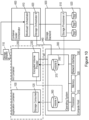
- FIGS 10 and 11 each illustrate such a system in accordance with an embodiment.
- the system illustrated in Figure 10 is as described earlier with reference to Figure 1 with the exception that the system illustrated in Figure 10 also comprises the encryption node 200 configured in the manner described earlier with reference to Figures 4 and 5 , the storage provisioning node 510 is configured in the manner described earlier with reference to Figures 6 and 7 , and the compute node 300 is configured in the manner described earlier with reference to Figures 8 and 9 .
- the system illustrated in Figure 11 is as described earlier with reference to Figure 2 with the exception that the system illustrated in Figure 11 also comprises the encryption node 200 configured in the manner described earlier with reference to Figures 4 and 5 , the storage provisioning node 510 is configured in the manner described earlier with reference to Figures 6 and 7 , and the compute node 300 is configured in the manner described earlier with reference to Figures 8 and 9 .
- the storage backend 500 comprises the storage provisioning node 510.
- storage is accessed over a network connection (e.g. software defined storage, network attached storage, etc.).
- the storage provisioning node 510 can comprise its own hardware as described earlier.
- the compute node 300 comprises the storage provisioning node 510.
- the hardware of the storage provisioning node 510 may be the same hardware as the compute node 300 as described earlier.
- the encryption node 200 and the operating system 350 of the compute node 300 may communicate via an interface 380.
- the processing circuitry of 202 of the encryption node 200 may comprise an encrypted volume provider module 220 for initiating provisioning of the encrypted storage volume 360 in the manner described herein.
- the encryption node 200 is associated with the application node (e.g. an application container or workload container) 100.
- the application node 100 and the encryption node 200 may operate using the same processing circuitry in the manner described earlier.
- the application node 100 can comprise a storage consuming entity 120.
- the storage consuming entity 120 may be configured to use (or consume) the encrypted storage 360 according to some embodiments.
- Figure 12 is a signalling (or call flow) diagram illustrating an exchange of signals in a system according to an embodiment.
- the system may be as illustrated in Figure 10 or 11 according to some embodiments.
- the system comprises the application node 100, the encryption container 200, the operating system (OS) 350 of the compute node 300, the storage provisioning node 510, and the orchestrator 400.
- the system illustrated in Figure 12 also comprises an application management node 600.
- the application management node 600 may be implemented in hardware and/or software, which is not shown.
- the steps 700, 702, 704, 706, 708, 710, 712 and 714 may be performed in the manner described earlier with reference to Figure 3 .
- the corresponding description of these steps with reference to Figure 3 will thus be understood to also apply to Figure 12 , even if they are not repeated here.
- the unencrypted storage volume 370 is made available at the compute node 100 to the encryption node 200 (rather than to the application node 100 as it is in step 706 of Figure 3 ).
- the deployment request (as illustrated by arrow 700 of Figure 12 ) transmitted by the application management node 600 to the orchestrator 400 may comprise a manifest.
- the manifest may, for example, be delivered as part of an application product package.
- the manifest may describe the storage needs of the application node 100.
- the manifest may comprise the description of the storage needs of the application node 100 and also a pointer to the storage provisioning node 510.
- provisioning of the unencrypted storage volume 370 is initiated by the storage provisioning node 510 (as illustrated by arrow 704 of Figure 12 ).
- the provisioning of the unencrypted storage volume 370 is initiated to make the unencrypted storage volume 370 available at (e.g. the operating system 350 of) the compute node 300 to the encryption node 200 in the manner described earlier with reference to Figures 6 and 7 .
- the first request 110 referred to herein may be triggered by an application product package deployment operation.
- the first request referred to herein may be served as an input to the orchestrator 400, e.g. at time of application deployment. This can be performed either directly by an administrator interacting with the orchestrator 400, e.g. through a user interface, or by the application management node 600.
- the unencrypted storage volume 370 is provisioned by (e.g. the operating system 350 of) the compute node 300 to make the requested unencrypted storage volume 370 available at the compute node 300 to the encryption node 200 in the manner described earlier with reference to Figures 8 and 9 .
- the unencrypted storage volume 370 is made available at the compute node 300 to the encryption node 200 for the encryption node 200 to use in the generation of an encrypted storage volume 360 to be made available at the compute node 300 for use by the application node 100.
- the first request may be acknowledged by the storage provisioning node 510 to the orchestrator 400 (as illustrated by arrow 708 of Figure 12 ).
- additional steps 902, 904, 906, 908 and 910 are also be performed according to the embodiment illustrated in Figure 12 .
- the orchestrator 400 can be configured to create the encryption node 200.
- the orchestrator 400 may transmit a request for the creation of the encrypton node 200 to the (e.g. operating system 350 of the) compute node 300.
- the (e.g. operating system 350 of the) compute node 300 can be configured to start (e.g. boot up) the encryption node 200.
- the (e.g. operating system 350 of the) compute node 300 may transmit a request to the encryption node 200 for the encryption node 200 to start.
- the encryption node 200 may be started only after the unencrypted storage volume 370 has become available to the encryption node 200.
- an encrypted storage volume 360 is generated by the encryption node 200 from the unencrypted storage volume 370 in the manner described earlier with reference to Figures 4 and 5 .
- an encrypted layer may be provided by the encryption node 200 (or any other node) for use in generating the encrypted storage volume 360.
- provisioning of the encrypted storage volume 360 is initiated by the encryption node to make the encrypted storage volume 360 available at the compute node 300 for use by the application node 100.
- the encrypted storage volume 360 generated by the encryption node 200 is provisioned by (e.g. the operating system 350 of) the compute node 300 to make the encrypted storage volume 360 available at the compute node 300 for use by the application node 100.
- the encryption node 200 may be terminated and the orchestrator 400 may be notified of the termination.
- the orchestrator 400 may transmit the request for the creation of the application node 100 (as illustrated by arrow 710 of Figure 12 ) upon termination of the encryption node 200.
- the operating system 350 of the) compute node 300 may then transmit the request for the application node 100 to start (as illustrated by arrow 712 of Figure 12 ). Once started, the application node 100 may use (or consume) the encrypted storage volume (as illustrated by block 714 of Figure 12 ).
- the method described herein in respect of the encryption node 200, the storage provisioning node 510 and/or the compute node 300 may be performed (e.g. may run to completion) prior to initiation of the application node 100, e.g. prior to the application node 100 starting (or booting up).
- the encrypted storage volume 360 is available at the compute node 300 for use by the application node 100 before the application node 100 is initiated, e.g. started (or booted up).
- the application node 100 may be initiated, e.g. started (or booted up), before encrypted storage volume 360 is available at the compute node 300.
- the application node 100 e.g.
- processing circuitry of the application node 100 may be configured to check whether the encrypted storage volume 360 is available at the compute node 300.
- the check may be performed by the application node 100 (e.g. processing circuitry of the application node 100) polling the compute node 300. The check may be performed, for example, continuously or at predefined time intervals.
- the orchestrator 400 may be configured to initiate, e.g. start (or boot up) the application node 100.
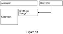
- Figure 13 illustrates an example environment in which a system (such as those described earlier) can be deployed in accordance with an embodiment.
- the example environment comprises a Kubernetes (which may also be referred to as a k8s) system, which can function as an orchestrator.
- the example environment also comprises a container storage interface (CSI) storage plugin and a helm chart.
- the environment also comprises an application that requires data storage. The method described herein can be used to provision this data storage.
- the application node 100 may select, e.g. via the helm chart, the type of storage that is provided by the storage provisioning node 510.
- FIG 14 is a block diagram illustrating an encryption node 1100 in accordance with an embodiment.
- the encryption node 1100 comprises a generating module 1102 configured to, in response to an unencrypted storage volume becoming available to the encryption node 1100 from a storage provisioning node of the system, generate an encrypted storage volume from the unencrypted storage volume.
- the encryption node 1100 comprises a provisioning initiating module 1104 configured to initiate provisioning of the encrypted storage volume to make the encrypted storage volume available at a compute node of the system for use by the application node.
- the encryption node 1100 may operate in the manner described herein.
- FIG. 15 is a block diagram illustrating a storage provisioning node 1200 in accordance with an embodiment.
- the storage provisioning node 1200 comprises a provisioning initiating module 1202 configured to, in response to a first request for an unencrypted storage volume, initiate provisioning of the unencrypted storage volume to make the unencrypted storage volume available at a compute node of the system to an encryption node for the encryption node to use in the generation of an encrypted storage volume to be made available at the compute node for use by an application node.
- the application node is configured to run at least part of one or more applications and the encryption node is associated with the application node.
- the storage provisioning node 1200 may also comprise an unprovisioning initiating module configured to initiate unprovisioning of the unencrypted storage volume to cease making the unencrypted storage volume available at the compute node.
- the storage provisioning node 1200 may operate in the manner described herein.
- Figure 16 is a block diagram illustrating a compute node 1300 in accordance with an embodiment.
- the compute node 1300 comprises a first provisioning module 1302 configured to provision a requested unencrypted storage volume to make the requested unencrypted storage volume available at the compute node 1300 to an encryption node 1100 for the encryption node 1100 to use in the generation of an encrypted storage volume.
- the compute node 1300 comprises a second provisioning module 1304 configured to provision the encrypted storage volume generated by the encryption node 1100 to make the encrypted storage volume available at the compute node 1300 for use by an application node.
- the compute node 1300 may also comprise an unprovisioning module configured to unprovision the unencrypted storage volume to cease making the unencrypted storage volume available at the compute node.
- the application node is configured to run at least part of one or more applications and the encryption node 1100 is associated with the application node.
- the compute node 1300 may operate in the manner described herein.
- processing circuitry such as the processing circuitry 202 of the encryption node 200 described earlier, the processing circuitry 502 of the storage provisioning node 510 described earlier, and/or the processing circuitry 310 of the compute node 300 described earlier, cause the processing circuitry to perform at least part of the method described herein.
- a computer program product embodied on a non-transitory machine-readable medium, comprising instructions which are executable by processing circuitry (such as the processing circuitry 202 of the encryption node 200 described earlier, the processing circuitry 502 of the storage provisioning node 510 described earlier, and/or the processing circuitry 310 of the compute node 300 described earlier) to cause the processing circuitry to perform at least part of the method described herein.
- processing circuitry such as the processing circuitry 202 of the encryption node 200 described earlier, the processing circuitry 502 of the storage provisioning node 510 described earlier, and/or the processing circuitry 310 of the compute node 300 described earlier
- a computer program product comprising a carrier containing instructions for causing processing circuitry (such as the processing circuitry 202 of the encryption node 200 described earlier, the processing circuitry 502 of the storage provisioning node 510 described earlier, and/or the processing circuitry 310 of the compute node 300 described earlier) to perform at least part of the method described herein.
- the carrier can be any one of an electronic signal, an optical signal, an electromagnetic signal, an electrical signal, a radio signal, a microwave signal, or a computer-readable storage medium.
- the encryption node functionality, the storage provisioning node functionality, and/or the compute node functionality described herein can be performed by hardware.
- any one or more of the encryption node 200, the storage provisioning node 510, and the compute node 300 described herein can be a hardware node.
- optionally at least part or all of the encryption node functionality, the storage provisioning node functionality, and/or the compute node functionality described herein can be virtualized.
- the functions performed by any one or more of the encryption node 200, the storage provisioning node 510, and the compute node 300 described herein can be implemented in software running on generic hardware that is configured to orchestrate the node functionality.
- the any one or more of the encryption node 200, the storage provisioning node 510, and the compute node 300 described herein can be a virtual node.
- at least part or all of the encryption node functionality, the storage provisioning node functionality, and/or the compute node functionality described herein may be performed in a network enabled cloud.
- the encryption node functionality, the storage provisioning node functionality, and/or the compute node functionality described herein may all be at the same location or at least some of the node functionality may be distributed.
- the encryption node 200 described herein can be deployed in any type of system including, but not limited to, any container based cloud system.
- the storage provisioning node 510 described herein can be any type of storage provisioning node including, but not limited to, any cloud system storage provisioner.
- the method described herein can be used with any workload that requires storage. Moreover, software support on the storage user side is not required.
Landscapes
- Engineering & Computer Science (AREA)
- Theoretical Computer Science (AREA)
- Computer Security & Cryptography (AREA)
- Computer Hardware Design (AREA)
- General Engineering & Computer Science (AREA)
- Physics & Mathematics (AREA)
- General Health & Medical Sciences (AREA)
- Software Systems (AREA)
- Bioethics (AREA)
- Health & Medical Sciences (AREA)
- General Physics & Mathematics (AREA)
- Databases & Information Systems (AREA)
- Computing Systems (AREA)
- Computer Networks & Wireless Communication (AREA)
- Signal Processing (AREA)
- Storage Device Security (AREA)
Description
- The disclosure relates to methods for provisioning storage in a system and nodes configured to operate in accordance with those methods.
- Applications (e.g. in the fifth generation (5G) core network) are increasingly following cloud native design principles and are being deployed in container-based data centers. Upon request, container-based data centers can provide persistent storage volumes to container workloads. These persistent storage volumes are provided using a component that is referred to as a storage provisioner or storage provisioning node.
-
Figures 1 and2 illustrate existing systems comprising such astorage provisioning node 510, which provides storage volumes to workloads. - Generally, data centers have a range of compute nodes (or hosts) 300 on which workloads are executed. As illustrated in
Figures 1 and2 , acompute node 300 often comprises processing circuitry (e.g. a processor) 310, amemory 320, anetwork interface 330 and optionally astorage interface 340. The workloads running on thecompute node 300 share an operating system (OS) 350. In some existing systems, such as the existing system illustrated inFigure 1 , storage is provided by astorage backend 500, which is attached to thecompute node 300 through a network using thenetwork interface 330. In these existing systems, thestorage backend 500 comprises thestorage provisioning node 510. In other existing systems, such as the existing system illustrated inFigure 2 , storage is directly attached by means of thestorage interface 340 to thecompute node 300. In these existing systems, theOS 350 of thecompute node 300 comprises thestorage provisioning node 510. - In the existing systems illustrated in
Figures 1 and2 , all data center resources are allocated to workloads by an orchestrator (e.g. a container cluster orchestrator) 400. Theorchestrator 400 comprises aworkload orchestrator 410 that orchestrates compute resources. Theorchestrator 400 also comprises astorage orchestrator 420 that orchestrates storage resources. Theworkload orchestrator 410 and thestorage orchestrator 420 can communicate via aninterface 430. In the existing systems illustrated inFigures 1 and2 , workloads run within an application node (e.g. an application container or workload container) 100. Typically, several application nodes (e.g. application containers or workload containers) 100 run on thesame compute node 300. Each of theseapplication nodes 100 can request one ormore storage volumes 360. The storage needs of a storage consumer (e.g. a user or an application) 120 that requires data storage are expressed within arequest 110 that is processed by theorchestrator 400 at the time of application node deployment. - The
workload orchestrator 410 uses thestorage orchestrator 420 to request storage from thestorage provisioning node 510. Thestorage provisioning node 510 maintains a pool ofstorage devices 520, reserves the requested amount of storage and makes it available to thecompute node 300. Thestorage orchestrator 420 uses aninterface 440 to the OS 350 on thecompute node 300 to create astorage volume 360 that is accessible to thestorage consumer 120. -
Figure 3 is a signalling (or call flow) diagram illustrating an exchange of signals in an existing system, such as those illustrated inFigures 1 and2 . The existing system illustrated inFigure 3 comprises theapplication node 100, theOS 350 of thecompute node 300, thestorage provisioning node 510, theorchestrator 400, and anapplication management node 600. - As illustrated by
arrow 700 ofFigure 3 , in existing systems, theapplication management node 600 transmits a deployment request towards theorchestrator 400. The deployment request is a request to deploy an application node (e.g. an application container or workload container) 100. In response to the deployment request, as illustrated byarrow 702 ofFigure 3 , theorchestrator 400 transmits a request for storage towards thestorage provisioning node 510. As illustrated byarrow 704 ofFigure 3 , in response to this request, thestorage provisioning node 510 transmits a request towards theOS 350 for theOS 350 to mount thestorage volume 360. As illustrated atblock 706 ofFigure 3 , theOS 350 mounts thestorage volume 360 to thecompute node 300 and thus thestorage volume 360 becomes available to the application node 100 (or, more specifically, the storage consumer 120). As illustrated byarrow 708 ofFigure 3 , the request for storage may be acknowledged by thestorage provisioning node 510 to theorchestrator 400. - As illustrated by
arrow 710 ofFigure 3 , theorchestrator 400 transmits a request towards the OS 350, which is a request for the OS 350 to create theapplication node 100. Then, theOS 350 allocates central processing unit (CPU) time for theapplication node 100 to run. Thus, as illustrated byarrow 712 ofFigure 3 , theOS 350 transmits a request towards theapplication node 100, which is a request for theapplication node 100 to start. Atblock 714 ofFigure 3 , theapplication node 100 uses (or consumes) thestorage volume 360. - In existing systems for provisioning storage, such as those described with reference to
Figures 1 ,2 and3 , data encryption has become mandatory in order for applications to comply with legal requirements related to personal data protection (e.g. the General Data Protection Regulation (GDPR)) and security. However, most of the storage provisioning node components that are currently available do not actually support volume encryption. Also, for databases that do not have built-in encryption functionality, it is desirable for the system infrastructure to provide encryption of data at rest. However, applications (e.g. 5G applications) are often deployed in different data centers for which the system infrastructure is not always fully controlled by a single party. Instead, it is usually necessary to work with different storage provisioning nodes, but most of these storage provisioning nodes do not actually support the encryption that is expected by the databases. - One solution to this is to implement similar software in a multitude of components in the system infrastructure. However, this creates recurring development costs, since similar software then needs to be created and implemented for every new component that is added to the system infrastructure and for every new application release. The application release dependency applies to encryption implemented in application nodes (e.g. application containers or workload containers). In this respect, encryption related software may be added to the application nodes (e.g. application containers). However, this can lead to licensing and support problems, particularly if these application nodes are third party products. Furthermore this creates recurring development costs, since similar software then needs to be created and implemented in every application that uses encrypted storage. It is also not acceptable to wait until all relevant storage provisioning nodes have been updated to support volume level encryption. There is no standard on how an encryption key may be passed to a storage provisioning node. Moreover, even if a storage provisioning node integrated in a data center supports encryption, the application needs to be adapted for each storage provisioning node that supports encryption to convey the key in the respective proprietary way.
-
WO2008037741 relates to encryption management for volumes in storage pools, wherein an encryption status indicates whether encryption is enabled for a pool or volume; -
US2008080706 relates to disk-based storage comprising encrypted and unencrypted data storage units; -
US2010211802 relates to a computing device accessing a storage volume encrypted using a technique unsupported by its operating system. - It is an object of the disclosure to obviate or eliminate at least some of the above-described disadvantages associated with existing systems.
- The claimed invention relates to a method, a node, a method, a node, a method, a node, a system and a computer program as defined in claims 1, 4, 6, 8, 10, 15, 17 and 18, respectively. Various embodiments are defined in the dependent claims.
- According to an aspect of the disclosure, there is provided a method for provisioning storage in a system. This method is performed by an encryption node. The encryption node is associated with an application node and the application node is configured to run at least part of one or more applications. The method comprises, in response to an unencrypted storage volume becoming available to the encryption node from a storage provisioning node of the system, generating an encrypted storage volume from the unencrypted storage volume and initiating provisioning of the encrypted storage volume to make the encrypted storage volume available at a compute node of the system for use by the application node.
- There is thus provided an advantageous method for provisioning storage in a system. In particular, the method supports volume level encryption. This encryption on a volume level allows finer granularity for the creation of security domains, for example, compared with storage encryption performed on device level. It allows every volume to be encrypted with a different key. Moreover, the method allows security requirements on storage encryption to be satisfied without being dependent on encryption functionality provided by cloud systems. It is possible to provide encrypted storage volumes to application nodes even if a data center does not support such functionality. The method also avoids the need for software to be created (or modified) and implemented for every storage provisioning node that is added to the system infrastructure and/or for every new application release, which provides easier development and integration. Moreover, licensing and support issues are mitigated since the method does not require encryption related software to be added to third party application nodes. The encrypted storage that is provided by way of the method can be used by any application node. It requires only a minimal additional software footprint and no extra storage footprint. There is also no impact on application nodes if the storage provisioning node is replaced with a different one. Moreover, different to encryption of data at rest on an infrastructure level, it allows the creation of different security domains on a per storage volume basis, e.g. by encrypting volumes with individual keys.
- In some embodiments, the method may be performed prior to initiation of the application node. This can be particularly advantageous in a system where the addition of volumes to already deployed nodes (e.g. containers) is not supported. Furthermore, where an application node (e.g. container) assumes a storage volume to be available from the start, error conditions (and even fatal error conditions) that the application node may otherwise run into can be avoided.
- In some embodiments, initiating provisioning of the encrypted storage volume to make the encrypted storage volume available at the compute node for use by the application node may comprise initiating mounting of the encrypted storage volume to the compute node to make the encrypted storage volume available at the compute node for use by the application node. In this way, it is possible to make storage volumes accessible in a root file system tree, which may be a precondition for using functionality provided by the operating system of the compute node to access storage, such as reading and/or writing.
- In some embodiments, initiating mounting of the encrypted storage volume to the compute node may comprise initiating mounting of the encrypted storage volume to a directory tree of the compute node. This can be particularly advantageous when the encrypted storage volume needs to be made available to multiple application nodes on the same compute node. In particular, having a separate mount point simplifies the adding and removing of application node specific mount points.
- In some embodiments, initiating provisioning of the encrypted storage volume to make the encrypted storage volume available at the compute node for use by the application node may comprise initiating generation of a hostpath volume for making the encrypted storage volume available to the application node.
- In some embodiments, the encrypted storage volume may be generated by applying an encrypted layer to the unencrypted storage volume.
- In some embodiments, the encrypted layer may be an encrypted file system layer.
- According to another aspect of the disclosure, there is provided an encryption node. The encryption node comprises processing circuitry configured to operate in accordance with the method described earlier in respect of the encryption node. The encryption node thus provides the advantages discussed earlier in respect of the method performed by the encryption node. In some embodiments, the encryption node comprises at least one memory for storing instructions which, when executed by the processing circuitry, cause the encryption node to operate in accordance with the method described earlier in respect of the encryption node.
- According to another aspect of the disclosure, there is provided another method for provisioning storage in a system. This method is performed by a storage provisioning node in the system. The method comprises, in response to a first request for an unencrypted storage volume, initiating provisioning of the unencrypted storage volume to make the unencrypted storage volume available at a compute node of the system to an encryption node for the encryption node to use in the generation of an encrypted storage volume to be made available at the compute node for use by an application node. The application node is configured to run at least part of one or more applications and the encryption node is associated with the application node.
- There is thus provided an advantageous method for provisioning storage in a system. In particular, the method supports volume level encryption. This encryption on a volume level allows finer granularity for the creation of security domains, for example, compared with storage encryption performed on device level. It allows every volume to be encrypted with a different key. Moreover, the method allows security requirements on storage encryption to be satisfied without being dependent on encryption functionality provided by cloud systems. It is possible to provide encrypted storage volumes to application nodes even if a data center does not support such functionality. The method also avoids the need for software to be created (or modified) and implemented for every storage provisioning node that is added to the system infrastructure and/or for every new application release, which provides easier development and integration. Moreover, licensing and support issues are mitigated since the method does not require encryption related software to be added to third party application nodes. The encrypted storage that is provided by way of the method can be used by any application node. It requires only a minimal additional software footprint and no extra storage footprint. There is also no impact on application nodes if the storage provisioning node is replaced with a different one. Moreover, different to encryption of data at rest on an infrastructure level, it allows the creation of different security domains on a per storage volume basis, e.g. by encrypting volumes with individual keys.
- In some embodiments, the method may be performed prior to initiation of the application node. This can be particularly advantageous in a system where the addition of volumes to already deployed nodes (e.g. containers) is not supported. Furthermore, where an application node (e.g. container) assumes a storage volume to be available from the start, error conditions (and even fatal error conditions) that the application node may otherwise run into can be avoided.
- In some embodiments, initiating provisioning of the unencrypted storage volume to make the unencrypted storage volume available at the compute node to the encryption node may comprise initiating mounting of the unencrypted storage volume to the compute node to make the unencrypted storage volume available to the encryption node. In this way, it is possible to make storage volumes accessible in a root file system tree, which may be a precondition for using functionality provided by the operating system of the compute node to access storage, such as reading and/or writing.
- In some embodiments, the compute node may be separate to the storage provisioning node. In this way, performance dependencies between the storage and application nodes running on compute nodes can be avoided. In some embodiments, the compute node may comprise the storage provisioning node. This allows easier scaling of the storage solution and reduces hardware cost by avoiding dedicated storage hardware and instead allows to make use of only one type of compute node (e.g. server) for the application nodes and storage.
- According to another aspect of the disclosure, there is provided a storage provisioning node. The storage provisioning node comprises processing circuitry configured to operate in accordance with the method described earlier in respect of the storage provisioning node. The storage provisioning node thus provides the advantages discussed earlier in respect of the method performed by the storage provisioning node. In some embodiments, the storage provisioning node comprises at least one memory for storing instructions which, when executed by the processing circuitry, cause the storage provisioning node to operate in accordance with the method described earlier in respect of the storage provisioning node.
- According to another aspect of the disclosure, there is provided another method for provisioning storage in a system. This method is performed by a compute node of the system. The method comprises provisioning a requested unencrypted storage volume to make the requested unencrypted storage volume available at the compute node to an encryption node for the encryption node to use in the generation of an encrypted storage volume and provisioning the encrypted storage volume generated by the encryption node to make the encrypted storage volume available at the compute node for use by an application node. The application node is configured to run at least part of one or more applications and the encryption node is associated with the application node.
- There is thus provided an advantageous method for provisioning storage in a system. In particular, the method supports volume level encryption. This encryption on a volume level allows finer granularity for the creation of security domains, for example, compared with storage encryption performed on device level. It allows every volume to be encrypted with a different key. Moreover, the method allows security requirements on storage encryption to be satisfied without being dependent on encryption functionality provided by cloud systems. It is possible to provide encrypted storage volumes to application nodes even if a data center does not support such functionality. The method also avoids the need for software to be created (or modified) and implemented for every storage provisioning node that is added to the system infrastructure and/or for every new application release, which provides easier development and integration. Moreover, licensing and support issues are mitigated since the method does not require encryption related software to be added to third party application nodes. The encrypted storage that is provided by way of the method can be used by any application node. It requires only a minimal additional software footprint and no extra storage footprint. There is also no impact on application nodes if the storage provisioning node is replaced with a different one. Moreover, different to encryption of data at rest on an infrastructure level, it allows the creation of different security domains on a per storage volume basis, e.g. by encrypting volumes with individual keys.
- In some embodiments, the method may be performed prior to initiation of the application node. This can be particularly advantageous in a system where the addition of volumes to already deployed nodes (e.g. containers) is not supported. Furthermore, where an application node (e.g. container) assumes a storage volume to be available from the start, error conditions (and even fatal error conditions) that the application node may otherwise run into can be avoided.
- In some embodiments, provisioning the encrypted storage volume to make the encrypted storage volume available at the compute node may comprise generating a hostpath volume for making the encrypted storage volume available to the application node.
- In some embodiments, provisioning the requested unencrypted storage volume to make the requested unencrypted storage volume available at the compute node to the encryption node may comprise mounting the requested unencrypted storage volume to the compute node to make the requested unencrypted storage volume available to the encryption node and/or provisioning the encrypted storage volume to make the encrypted storage volume available at the compute node for use by the application node may comprise mounting the encrypted storage volume to the compute node to make the encrypted storage volume available at the compute node for use by the application node. In this way, it is possible to make storage volumes accessible in the root file system tree, which may be a precondition for using functionality provided by the operating system of the compute node to access storage, such as reading and/or writing.
- In some embodiments, mounting the requested unencrypted storage volume to the compute node may comprise mounting the requested unencrypted storage volume to a directory tree of the compute node and/or mounting the encrypted storage volume to the compute node may comprise mounting the encrypted storage volume to the directory tree of the compute node. This can be particularly advantageous when the encrypted storage volume needs to be made available to multiple application nodes on the same compute node. In particular, having a separate mount point simplifies the adding and removing of application node specific mount points.
- In some embodiments, the method may comprise unmounting the unencrypted storage volume from the compute node and/or unmounting the encrypted storage volume from the compute node. This can be particularly advantageous when the application node that consumes the encrypted volume is terminated on the compute node, for example, due to decommissioning of the application node or an orchestrator deciding to run the application node on a different compute node.
- In some embodiments, the method may comprise, in response to termination of an application node that uses the encrypted storage volume, removing a configuration related to the encrypted storage volume from the compute node.
- In some embodiments, the compute node may be separate to a storage provisioning node of the system. In this way, performance dependencies between the storage and application nodes running on compute nodes can be avoided. In some embodiments, the compute node may comprise a storage provisioning node of the system. This allows easier scaling of the storage solution and reduces hardware cost by avoiding dedicated storage hardware and instead allows to make use of only one type of compute node (e.g. server) for the application nodes and storage.
- According to another aspect of the disclosure, there is provided a compute node. The compute node comprises processing circuitry configured to operate in accordance with the method described earlier in respect of the compute node. The compute node thus provides the advantages discussed earlier in respect of the method performed by the compute node. In some embodiments, the compute node comprises at least one memory for storing instructions which, when executed by the processing circuitry, cause the compute node to operate in accordance with the method described earlier in respect of the compute node.
- According to another aspect of the disclosure, there is provided a system. The system comprises one or more encryption nodes as described earlier, one or more storage provisioning nodes as described earlier and/or one or more compute nodes as described earlier. The system thus provides the advantages discussed earlier in respect of the method performed by the encryption node, storage provisioning node and/or compute node.
- According to another aspect of the disclosure, there is provided a computer program comprising instructions which, when executed by processing circuitry, cause the processing circuitry to perform the method described earlier in respect of the encryption node, storage provisioning node and/or compute node. The computer program thus provides the advantages discussed earlier in respect of the method performed by the encryption node, storage provisioning node and/or compute node.
- According to another aspect of the disclosure, there is provided a computer program product, embodied on a non-transitory machine-readable medium, comprising instructions which are executable by processing circuitry to cause the processing circuitry to perform the method described earlier in respect of the encryption node, storage provisioning node and/or compute node. The computer program product thus provides the advantages discussed earlier in respect of the method performed by the encryption node, storage provisioning node and/or compute node.
- Therefore, an advantageous technique for provisioning storage in a system is provided.
- For a better understanding of the technique, and to show how it may be put into effect, reference will now be made, by way of example, to the accompanying drawings, in which:
-
Figure 1 is a block diagram illustrating an existing system; -
Figure 2 is a block diagram illustrating an existing system; -
Figure 3 is a signalling diagram illustrating an exchange of signals in an existing system; -
Figure 4 is a block diagram illustrating an encryption node according to an embodiment; -
Figure 5 is a block diagram illustrating a method performed by an encryption node according to an embodiment; -
Figure 6 is a block diagram illustrating a storage provisioning node according to an embodiment; -
Figure 7 is a block diagram illustrating a method performed by a storage provisioning node according to an embodiment; -
Figure 8 is a block diagram illustrating a compute node according to an embodiment; -
Figure 9 is a block diagram illustrating a method performed by a compute node according to an embodiment; -
Figure 10 is a block diagram illustrating a system according to an embodiment; -
Figure 11 is a block diagram illustrating a system according to an embodiment; -
Figure 12 is a signalling diagram illustrating an exchange of signals in a system according to an embodiment; -
Figure 13 is a block diagram illustrating an example environment for a system according to an embodiment; -
Figure 14 is a block diagram illustrating an encryption node according to an embodiment; -
Figure 15 is a block diagram illustrating a storage provisioning node according to an embodiment; and -
Figure 16 is a block diagram illustrating a compute node according to an embodiment. - As mentioned earlier, an advantageous technique for provisioning storage in a system is described herein. More specifically, the technique described herein provisions storage volumes in a network. Herein, a storage volume can be any unit of storage. The storage volumes referred to herein can be configured to store data, information, objects, etc. In some embodiments, a storage volume may be a file system. The technique described herein is implemented by an encryption node, a storage provisioning node and a compute node.
- The technique described herein may, for example, be applied to data centers, such as data centers that use container technology. These data centers that use container technology may also be referred to as cloud data centers. Generally, workloads may be distributed over multiple containers. The multiple containers can be scheduled to execute on a plurality of compute nodes (or hosts). An agent of a storage provisioner may be present on each compute node. The agent may communicate with an operating system of the compute node.
- According to some embodiments, the system described herein for which storage is provisioned may comprise a plurality of compute nodes that are configured in the manner described herein. A plurality of compute nodes may also be referred to as a cluster. Herein, provisioning storage or storage provisioning can be defined as the process of assigning storage and making that storage available to an application node, e.g. for read and/or write operations.
-
Figure 4 illustrates anencryption node 200 in accordance with an embodiment. Theencryption node 200 is for provisioning storage in a system. Theencryption node 200 is associated with an application node. Theapplication node 200 is configured to run at least part of one or more applications. Theencryption node 200 may, for example, be a physical machine (e.g. a server) or a virtual machine (VM). - As illustrated in
Figure 4 , theencryption node 200 comprises processing circuitry (or logic) 202. Theprocessing circuitry 202 controls the operation of theencryption node 200 and can implement the method described herein in respect of theencryption node 200. Theprocessing circuitry 202 can be configured or programmed to control theencryption node 200 in the manner described herein. Theprocessing circuitry 202 can comprise one or more hardware components, such as one or more processors, one or more processing units, one or more multi-core processors, and/or one or more modules. In particular implementations, each of the one or more hardware components can be configured to perform, or is for performing, individual or multiple steps of the method described herein in respect of theencryption node 200. In some embodiments, theprocessing circuitry 202 can be configured to run software to perform the method described herein in respect of theencryption node 200. The software may be containerised according to some embodiments. Thus, in some embodiments, theprocessing circuitry 202 may be configured to run a container (e.g. an init container) to perform the method described herein in respect of theencryption node 200. This container may run in privileged mode. - Briefly, the
processing circuitry 202 of theencryption node 200 is configured to, in response to an unencrypted storage volume becoming available to the encryption node from a storage provisioning node of the system, generate an encrypted storage volume from the unencrypted storage volume and initiate provisioning of the encrypted storage volume to make the encrypted storage volume available at a compute node of the system for use by the application node. - As illustrated in
Figure 4 , in some embodiments, theencryption node 200 may optionally comprise amemory 204. Thememory 204 of theencryption node 200 can comprise a volatile memory or a non-volatile memory. In some embodiments, thememory 204 of theencryption node 200 may comprise a non-transitory media. Examples of thememory 204 of theencryption node 200 include, but are not limited to, a random access memory (RAM), a read only memory (ROM), a mass storage media such as a hard disk, a removable storage media such as a compact disk (CD) or a digital video disk (DVD), and/or any other memory. - The
processing circuitry 202 of theencryption node 200 can be connected to thememory 204 of theencryption node 200. In some embodiments, thememory 204 of theencryption node 200 may be for storing program code or instructions which, when executed by theprocessing circuitry 202 of theencryption node 200, cause theencryption node 200 to operate in the manner described herein in respect of theencryption node 200. For example, in some embodiments, thememory 204 of theencryption node 200 may be configured to store program code or instructions that can be executed by theprocessing circuitry 202 of theencryption node 200 to cause theencryption node 200 to operate in accordance with the method described herein in respect of theencryption node 200. Alternatively or in addition, thememory 204 of theencryption node 200 can be configured to store any information, data, messages, requests, responses, indications, notifications, signals, or similar, that are described herein. Theprocessing circuitry 202 of theencryption node 200 may be configured to control thememory 204 of theencryption node 200 to store information, data, messages, requests, responses, indications, notifications, signals, or similar, that are described herein. - In some embodiments, as illustrated in
Figure 4 , theencryption node 200 may optionally comprise acommunications interface 206. The communications interface 206 of theencryption node 200 can be connected to theprocessing circuitry 202 of theencryption node 200 and/or thememory 204 ofencryption node 200. The communications interface 206 of theencryption node 200 may be operable to allow theprocessing circuitry 202 of theencryption node 200 to communicate with thememory 204 of theencryption node 200 and/or vice versa. Similarly, thecommunications interface 206 of theencryption node 200 may be operable to allow theprocessing circuitry 202 of theencryption node 200 to communicate with the storage provisioning node, compute node and/or any other node. The communications interface 206 of theencryption node 200 can be configured to transmit and/or receive information, data, messages, requests, responses, indications, notifications, signals, or similar, that are described herein. In some embodiments, theprocessing circuitry 202 of theencryption node 200 may be configured to control thecommunications interface 206 of theencryption node 200 to transmit and/or receive information, data, messages, requests, responses, indications, notifications, signals, or similar, that are described herein. - Although the
encryption node 200 is illustrated inFigure 4 as comprising asingle memory 204, it will be appreciated that theencryption node 200 may comprise at least one memory (i.e. a single memory or a plurality of memories) 204 that operate in the manner described herein. Similarly, although theencryption node 200 is illustrated inFigure 4 as comprising asingle communications interface 206, it will be appreciated that theencryption node 200 may comprise at least one communications interface (i.e. a single communications interface or a plurality of communications interface) 206 that operate in the manner described herein. - It will also be appreciated that
Figure 4 only shows the components required to illustrate an embodiment of theencryption node 200 and, in practical implementations, theencryption node 200 may comprise additional or alternative components to those shown. - In some embodiments, the hardware (
e.g. processing circuitry 202,memory 204, and/or communications interface 206) that can implement the method described herein in respect of theencryption node 200 may be the same hardware as that which implements the method performed by the application node that is associated with theencryption node 200. For example, the same hardware (e.g. processing circuitry, memory, and/or communications interface) that is configured to run at least part of one or more applications may also be configured to implement the method described herein in respect of theencryption node 200. In some embodiments, the hardware that can implement the method described herein in respect of theencryption node 200 and/or the hardware that can implement the method described herein in respect of the application node may be the same hardware as that which implements the method performed by a compute node (e.g. of a cluster of compute nodes), such as the compute node described herein. -
Figure 5 is a flowchart illustrating a method performed by anencryption node 200 in accordance with an embodiment. The method is for provisioning storage in a system. Theencryption node 200 described earlier with reference toFigure 4 is configured to operate in accordance with the method ofFigure 5 . The method can be performed by or under the control of theprocessing circuitry 202 of theencryption node 200. - As illustrated in
Figure 5 , atblock 20, in response to an unencrypted storage volume becoming available to the encryption node from a storage provisioning node of the system, an encrypted storage volume is generated from the unencrypted storage volume. More specifically, theprocessing circuitry 202 of theencryption node 200 generates the encrypted storage volume from the unencrypted storage volume. In some embodiments, the generation of the encrypted storage volume may be performed in response to a request for an unencrypted storage volume, e.g. at deployment of the application node. - In some embodiments, the encrypted storage volume may be generated by applying an encrypted layer to the unencrypted storage volume. More specifically, in some embodiments, the
processing circuitry 202 of theencryption node 200 can be configured to apply the encrypted layer to the unencrypted storage volume. In some embodiments, the application of the encrypted layer may be chosen when the unencrypted storage volume is provided with an unencrypted file system. In some embodiments, the encrypted layer may be an encrypted file system layer. For example, an encrypted file system may be deployed as a layer on top of the unencrypted storage volume. In some embodiments, an encrypted file system layer may be chosen when the unencrypted storage volume is an unencrypted raw block storage (i.e. when only an unencrypted storage device is provided, without a file system). This can provide performance benefits. The unencrypted storage volume may itself be an unencrypted file system. In some embodiments, the encrypted layer may be provided by theencryption node 200. In other embodiments, another node may provide the encrypted layer. - In an example approach for generating the encrypted storage volume, the
processing circuitry 202 of theencryption node 200 may generate a file and use a device mapper functionality (e.g. where a file from the unencrypted storage volume is exposed as an encrypted storage device, which is formatted with another file system) to create an encrypted storage device as the encrypted storage volume referred to herein. In some embodiments, theprocessing circuitry 202 of theencryption node 200 may first format the device with a filesystem and then use this filesystem as the encrypted storage volume referred to herein. In another example approach for generating the encrypted storage volume, theprocessing circuitry 202 of theencryption node 200 may format a (raw) block storage device with a filesystem that supports encryption and use this filesystem as the encrypted storage volume referred to herein. - Returning back to
Figure 5 , atblock 22, provisioning of the encrypted storage volume is initiated to make the encrypted storage volume available at a compute node of the system for use by the application node. More specifically, in some embodiments, theprocessing circuitry 202 of theencryption node 200 initiates the provisioning of the encrypted storage volume. For example, theprocessing circuitry 202 of theencryption node 200 may be configured to instruct (e.g. an operating system of) thecompute node 300 to make the encrypted storage volume available for use by the application node. In some embodiments, theprocessing circuitry 202 of theencryption node 200 may be configured to initiate transmission of (e.g. itself transmit or cause another node to transmit) the instruction towards (e.g. an operating system of) the compute node. The instruction may be for thecompute node 300 to publish the encrypted storage volume for use by the application node. - In some embodiments, initiating provisioning of the encrypted storage volume at
block 22 ofFigure 5 to make the encrypted storage volume available at the compute node for use by the application node may comprise initiating mounting of the encrypted storage volume to the compute node to make the encrypted storage volume available at the compute node for use by the application node. In some of these embodiments, initiating mounting of the encrypted storage volume to the compute node may comprise initiating mounting of the encrypted storage volume to a directory tree of the compute node. A person skilled in the art will appreciate that mounting of the encrypted storage volume to the compute node is only one example of the manner in which the encrypted storage volume can be made available at the compute node for use by the application node and that other examples are also possible. For example, in some embodiments, the encrypted storage volume can be made available at the compute node for use by the application node through other interfaces, such as a hypertext transfer protocol (HTTP) interface. This can be particularly useful for object storage. - In some embodiments, initiating provisioning of the encrypted storage volume at
block 22 ofFigure 5 to make the encrypted storage volume available at the compute node for use by the application node may comprise initiating generation of a hostpath volume for making the encrypted storage volume available to the application node. Thus, in some embodiments, the application node may have a hostpath volume configured. In some embodiments, this may trigger an orchestrator to allocate a path within a directory tree of a host file system that is accessible to the application node. -
Figure 6 illustrates astorage provisioning node 510 in accordance with an embodiment. Thestorage provisioning node 510 is for provisioning storage in a system. Thestorage provisioning node 510 may, for example, be a physical machine (e.g. a server) or a virtual machine (VM). - As illustrated in
Figure 6 , thestorage provisioning node 510 comprises processing circuitry (or logic) 502. Theprocessing circuitry 502 controls the operation of thestorage provisioning node 510 and can implement the method described herein in respect of thestorage provisioning node 510. Theprocessing circuitry 502 can be configured or programmed to control thestorage provisioning node 510 in the manner described herein. Theprocessing circuitry 502 can comprise one or more hardware components, such as one or more processors, one or more processing units, one or more multi-core processors, and/or one or more modules. In particular implementations, each of the one or more hardware components can be configured to perform, or is for performing, individual or multiple steps of the method described herein in respect of thestorage provisioning node 510. In some embodiments, theprocessing circuitry 502 can be configured to run software to perform the method described herein in respect of thestorage provisioning node 510. The software may be containerised according to some embodiments. Thus, in some embodiments, theprocessing circuitry 502 may be configured to run a container to perform the method described herein in respect of thestorage provisioning node 510. - Briefly, the
processing circuitry 502 of thestorage provisioning node 510 is configured to, in response to a first request for an unencrypted storage volume, initiate provisioning of the unencrypted storage volume to make the unencrypted storage volume available at a compute node of the system to anencryption node 200 for theencryption node 200 to use in the generation of an encrypted storage volume to be made available at the compute node for use by an application node. The application node is configured to run at least part of one or more applications and theencryption node 200 is associated with the application node. - As illustrated in
Figure 6 , in some embodiments, thestorage provisioning node 510 may optionally comprise amemory 520. Thememory 520 of thestorage provisioning node 510 can comprise a volatile memory or a non-volatile memory. In some embodiments, thememory 520 of thestorage provisioning node 510 may comprise a non-transitory media. Examples of thememory 520 of thestorage provisioning node 510 include, but are not limited to, a random access memory (RAM), a read only memory (ROM), a mass storage media such as a hard disk, a removable storage media such as a compact disk (CD) or a digital video disk (DVD), and/or any other memory. In some embodiments, thememory 520 of thestorage provisioning node 510 may comprise one or more storage devices, e.g. a pool of storage devices. - The
processing circuitry 502 of thestorage provisioning node 510 can be connected to thememory 520 of thestorage provisioning node 510. In some embodiments, thememory 520 of thestorage provisioning node 510 may be for storing program code or instructions which, when executed by theprocessing circuitry 502 of thestorage provisioning node 510, cause thestorage provisioning node 510 to operate in the manner described herein in respect of thestorage provisioning node 510. For example, in some embodiments, thememory 520 of thestorage provisioning node 510 may be configured to store program code or instructions that can be executed by theprocessing circuitry 502 of thestorage provisioning node 510 to cause thestorage provisioning node 510 to operate in accordance with the method described herein in respect of thestorage provisioning node 510. Alternatively or in addition, thememory 520 of thestorage provisioning node 510 can be configured to store any information, data, messages, requests, responses, indications, notifications, signals, or similar, that are described herein. Theprocessing circuitry 502 of thestorage provisioning node 510 may be configured to control thememory 520 of thestorage provisioning node 510 to store information, data, messages, requests, responses, indications, notifications, signals, or similar, that are described herein. - In some embodiments, as illustrated in
Figure 6 , thestorage provisioning node 510 may optionally comprise acommunications interface 506. The communications interface 506 of thestorage provisioning node 510 can be connected to theprocessing circuitry 502 of thestorage provisioning node 510 and/or thememory 520 ofstorage provisioning node 510. The communications interface 506 of thestorage provisioning node 510 may be operable to allow theprocessing circuitry 502 of thestorage provisioning node 510 to communicate with thememory 520 of thestorage provisioning node 510 and/or vice versa. Similarly, thecommunications interface 506 of thestorage provisioning node 510 may be operable to allow theprocessing circuitry 502 of thestorage provisioning node 510 to communicate with the encryption node, compute node and/or any other node. The communications interface 506 of thestorage provisioning node 510 can be configured to transmit and/or receive information, data, messages, requests, responses, indications, notifications, signals, or similar, that are described herein. In some embodiments, theprocessing circuitry 502 of thestorage provisioning node 510 may be configured to control thecommunications interface 506 of thestorage provisioning node 510 to transmit and/or receive information, data, messages, requests, responses, indications, notifications, signals, or similar, that are described herein. - Although the
storage provisioning node 510 is illustrated inFigure 6 as comprising asingle memory 520, it will be appreciated that thestorage provisioning node 510 may comprise at least one memory (i.e. a single memory or a plurality of memories) 520 that operate in the manner described herein. Similarly, although thestorage provisioning node 510 is illustrated inFigure 6 as comprising asingle communications interface 506, it will be appreciated that thestorage provisioning node 510 may comprise at least one communications interface (i.e. a single communications interface or a plurality of communications interface) 506 that operate in the manner described herein. - It will also be appreciated that
Figure 6 only shows the components required to illustrate an embodiment of thestorage provisioning node 510 and, in practical implementations, thestorage provisioning node 510 may comprise additional or alternative components to those shown. - In some embodiments, the hardware (
e.g. processing circuitry 502,memory 520, and/or communications interface 506) that can implement the method described herein in respect of thestorage provisioning node 510 may be the same hardware as that which implements the method performed by a compute node (e.g. of a cluster of compute nodes), such as the compute node described herein. For example, in some embodiments, thestorage provisioning node 510 may be software that the hardware (e.g. processing circuitry) of the compute node can run to implement the method described herein in respect of thestorage provisioning node 510. In other embodiments, the hardware (e.g. processing circuitry 502,memory 520, and/or communications interface 506) that can implement the method described herein in respect of thestorage provisioning node 510 may be the hardware of a storage backend node that comprises thestorage provisioning node 510. For example, in some embodiments, thestorage provisioning node 510 may be software that the hardware (e.g. processing circuitry) of the storage backend node can run to implement the method described herein in respect of thestorage provisioning node 510. -
Figure 7 is a flowchart illustrating a method performed by astorage provisioning node 510 in accordance with an embodiment. The method is for provisioning storage in a system. Thestorage provisioning node 510 described earlier with reference toFigure 6 is configured to operate in accordance with the method ofFigure 7 . The method can be performed by or under the control of theprocessing circuitry 502 of thestorage provisioning node 510. - As illustrated in
Figure 7 , atblock 50, in response to a first request for an unencrypted storage volume, provisioning of the unencrypted storage volume is initiated to make the unencrypted storage volume available at a compute node of the system to anencryption node 200 for theencryption node 200 to use in the generation of an encrypted storage volume to be made available at the compute node for use by an application node. More specifically, theprocessing circuitry 502 of thestorage provisioning node 510 initiates the provisioning of the unencrypted storage volume. For example, theprocessing circuitry 502 of thestorage provisioning node 510 may be configured to instruct (e.g. an operating system of) the compute node to make the unencrypted storage volume available to theencryption node 200. In some embodiments, theprocessing circuitry 502 of thestorage provisioning node 510 may be configured to initiate transmission of (e.g. itself transmit or cause another node to transmit) the instruction towards (e.g. an operating system of) the compute node. The instruction may be for the compute node to publish the unencrypted storage volume system to theencryption node 200. - The application node is configured to run at least part of one or more applications and the
encryption node 200 is associated with the application node. - In some embodiments, initiating provisioning of the unencrypted storage volume to make the unencrypted storage volume available at the compute node to the
encryption node 200 may comprise initiating mounting of the unencrypted storage volume to the compute node to make the unencrypted storage volume available to theencryption node 200. A person skilled in the art will appreciate that mounting of the unencrypted storage volume to the compute node is only one example of the manner in which the unencrypted storage volume can be made available at the compute node to theencryption node 200 and that other examples are also possible. For example, in some embodiments, the unencrypted storage volume can be made available at the compute node to theencryption node 200 through other interfaces, such as a hypertext transfer protocol (HTTP) interface. This can be particularly useful for object storage. - In some embodiments, the compute node may be separate to the
storage provisioning node 510. For example, the storage provisioning node 510 (or, in some embodiments, thestorage backend 500 that comprises the storage provisioning node 510) may be an entity that is separate to the compute node described herein, with its own dedicated software and/or hardware. In other embodiments, the compute node may comprise thestorage provisioning node 510. For example, in some embodiments, the method described herein in respect of thestorage provisioning node 510 may be running as (e.g. containerised) software on the compute node described herein. In some embodiments, the compute node described herein may at the same time be running (e.g. containerised) application software. This may be referred to as "hyperconverged software defined storage". Alternatively, in some embodiments, the compute node described herein may be exclusively used for storage. This may be referred to as "software defined storage". In some embodiments involving a cluster, the method described herein in respect of thestorage provisioning node 510 may be running as (e.g. containerised) software on one or more (or each) of the plurality of compute nodes. - Although not illustrated in
Figure 7 , in some embodiments, the method may comprise initiating unprovisioning of the unencrypted storage volume to cease making the unencrypted storage volume available at the compute node. More specifically, theprocessing circuitry 502 of thestorage provisioning node 510 may be configured to initiate the unprovisioning of the unencrypted storage volume. For example, theprocessing circuitry 502 of thestorage provisioning node 510 may be configured to instruct (e.g. an operating system of) the compute node to cease making the unencrypted storage volume available. In some embodiments, theprocessing circuitry 502 of thestorage provisioning node 510 may be configured to initiate transmission of (e.g. itself transmit or cause another node to transmit) the instruction towards (e.g. an operating system of) the compute node. -
Figure 8 illustrates acompute node 300 in accordance with an embodiment. Thecompute node 300 is for provisioning storage in a system. Thecompute node 300 may also be referred to herein as a compute host. Thecompute node 300 may, for example, be a physical machine (e.g. a server) or a virtual machine (VM). In some embodiments, thecompute node 300 can be configured to run (e.g. the software for) the application node referred to herein. - As illustrated in
Figure 8 , thecompute node 300 comprises processing circuitry (or logic) 310. Theprocessing circuitry 310 controls the operation of thecompute node 300 and can implement the method described herein in respect of thecompute node 300. Theprocessing circuitry 310 can be configured or programmed to control thecompute node 300 in the manner described herein. Theprocessing circuitry 310 can comprise one or more hardware components, such as one or more processors, one or more processing units, one or more multi-core processors, and/or one or more modules. In particular implementations, each of the one or more hardware components can be configured to perform, or is for performing, individual or multiple steps of the method described herein in respect of thecompute node 300. In some embodiments, theprocessing circuitry 310 can be configured to run software to perform the method described herein in respect of thecompute node 300. The software may be containerised according to some embodiments. Thus, in some embodiments, theprocessing circuitry 310 may be configured to run a container to perform the method described herein in respect of thecompute node 300. - Briefly, the
processing circuitry 310 of thecompute node 300 is configured to provision a requested unencrypted storage volume to make the requested unencrypted storage volume available at thecompute node 300 to anencryption node 200 for theencryption node 200 to use in the generation of an encrypted storage volume. Theprocessing circuitry 310 of thecompute node 300 is also configured to provision the encrypted storage volume generated by theencryption node 200 to make the encrypted storage volume available at thecompute node 300 for use by an application node. The application node is configured to run at least part of one or more applications and theencryption node 200 is associated with the application node. - As illustrated in
Figure 8 , in some embodiments, thecompute node 300 may optionally comprise amemory 320. Thememory 320 of thecompute node 300 can comprise a volatile memory or a non-volatile memory. In some embodiments, thememory 320 of thecompute node 300 may comprise a non-transitory media. Examples of thememory 320 of thecompute node 300 include, but are not limited to, a random access memory (RAM), a read only memory (ROM), a mass storage media such as a hard disk, a removable storage media such as a compact disk (CD) or a digital video disk (DVD), and/or any other memory. - The
processing circuitry 310 of thecompute node 300 can be connected to thememory 320 of thecompute node 300. In some embodiments, thememory 320 of thecompute node 300 may be for storing program code or instructions which, when executed by theprocessing circuitry 310 of thecompute node 300, cause thecompute node 300 to operate in the manner described herein in respect of thecompute node 300. For example, in some embodiments, thememory 320 of thecompute node 300 may be configured to store program code or instructions that can be executed by theprocessing circuitry 310 of thecompute node 300 to cause thecompute node 300 to operate in accordance with the method described herein in respect of thecompute node 300. Alternatively or in addition, thememory 320 of thecompute node 300 can be configured to store any information, data, messages, requests, responses, indications, notifications, signals, or similar, that are described herein. The processing circuitry 31 0 of thecompute node 300 may be configured to control thememory 320 of thecompute node 300 to store information, data, messages, requests, responses, indications, notifications, signals, or similar, that are described herein. - In some embodiments, as illustrated in
Figure 8 , thecompute node 300 may optionally comprise acommunications interface 306, e.g. a network interface and/or a storage interface. The communications interface 306 of thecompute node 300 can be connected to theprocessing circuitry 310 of thecompute node 300 and/or thememory 320 ofcompute node 300. The communications interface 306 of thecompute node 300 may be operable to allow theprocessing circuitry 310 of thecompute node 300 to communicate with thememory 320 of thecompute node 300 and/or vice versa. Similarly, thecommunications interface 306 of thecompute node 300 may be operable to allow theprocessing circuitry 310 of thecompute node 300 to communicate with the storage provisioning node, encryption node and/or any other node. The communications interface 306 of thecompute node 300 can be configured to transmit and/or receive information, data, messages, requests, responses, indications, notifications, signals, or similar, that are described herein. In some embodiments, theprocessing circuitry 310 of thecompute node 300 may be configured to control thecommunications interface 306 of thecompute node 300 to transmit and/or receive information, data, messages, requests, responses, indications, notifications, signals, or similar, that are described herein. - Although the
compute node 300 is illustrated inFigure 8 as comprising asingle memory 320, it will be appreciated that thecompute node 300 may comprise at least one memory (i.e. a single memory or a plurality of memories) 320 that operate in the manner described herein. Similarly, although thecompute node 300 is illustrated inFigure 8 as comprising asingle communications interface 306, it will be appreciated that thecompute node 300 may comprise at least one communications interface (i.e. a single communications interface or a plurality of communications interface) 306 that operate in the manner described herein. - It will also be appreciated that
Figure 8 only shows the components required to illustrate an embodiment of thecompute node 300 and, in practical implementations, thecompute node 300 may comprise additional or alternative components to those shown. - As mentioned earlier, in some embodiments, the hardware (
e.g. processing circuitry 310,memory 320, and/or communications interface 306) that can implement the method described herein in respect of thecompute node 300 may also be used to implement the method described herein in respect of theencryption node 200 and/or the method described herein in respect of the application node. As also mentioned earlier, in some embodiments, the hardware (e.g. processing circuitry 310,memory 320, and/or communications interface 306) that can implement the method described herein in respect of thecompute node 300 may also be used to implement the method performed by thestorage provisioning node 510. -
Figure 9 is a flowchart illustrating a method performed by acompute node 300 in accordance with an embodiment. The method is for provisioning storage in a system. Thecompute node 300 described earlier with reference toFigure 8 is configured to operate in accordance with the method ofFigure 9 . The method can be performed by or under the control of theprocessing circuitry 310 of thecompute node 300. - As illustrated in
Figure 9 , atblock 30, a requested unencrypted storage volume is provisioned to make the requested unencrypted storage volume available at thecompute node 300 to anencryption node 200 for theencryption node 200 to use in the generation of an encrypted storage volume. More specifically, theprocessing circuitry 310 of thecompute node 300 provisions the requested unencrypted storage volume. - In some embodiments, provisioning the requested unencrypted storage volume at
block 30 ofFigure 9 to make the requested unencrypted storage volume available at thecompute node 300 to theencryption node 200 may comprise mounting the requested unencrypted storage volume to thecompute node 300 to make the requested unencrypted storage volume available to theencryption node 200. In some embodiments, mounting the requested unencrypted storage volume to thecompute node 300 may comprise mounting the requested unencrypted storage volume to a directory tree of thecompute node 300. As mentioned earlier, a person skilled in the art will appreciate that mounting of the unencrypted storage volume to the compute node is only one example of the manner in which the unencrypted storage volume can be made available at the compute node to theencryption node 200 and that other examples are also possible. For example, in some embodiments, the unencrypted storage volume can be made available at the compute node to theencryption node 200 through other interfaces, such as a hypertext transfer protocol (HTTP) interface. This can be particularly useful for object storage. - Returning back to
Figure 9 , atblock 32, the encrypted storage volume generated by theencryption node 200 is provisioned to make the encrypted storage volume available at thecompute node 300 for use by an application node. More specifically, theprocessing circuitry 310 of thecompute node 300 provisions the encrypted storage volume. - In some embodiments, provisioning the encrypted storage volume at
block 32 ofFigure 9 to make the encrypted storage volume available at thecompute node 300 for use by the application node may comprise mounting the encrypted storage volume to thecompute node 300 to make the encrypted storage volume available at thecompute node 300 for use by the application node. In some embodiments, mounting the encrypted storage volume to thecompute node 300 may comprise mounting the encrypted storage volume to the directory tree of thecompute node 300. A person skilled in the art will appreciate that mounting of the encrypted storage volume to the compute node is only one example of the manner in which the encrypted storage volume can be made available at the compute node for use by the application node and that other examples are also possible. For example, in some embodiments, the encrypted storage volume can be made available at the compute node for use by the application node through other interfaces, such as a hypertext transfer protocol (HTTP) interface. This can be particularly useful for object storage. - In some embodiments, provisioning the encrypted storage volume at
block 32 ofFigure 9 to make the encrypted storage volume available at thecompute node 300 may comprise generating a hostpath volume for making the encrypted storage volume available to the application node. In some embodiments, this may trigger an orchestrator to allocate a path within a directory tree of a host file system that is accessible to the application node. - Although not illustrated in
Figure 9 , in some embodiments, the method may comprise ceasing to make the unencrypted storage volume available at thecompute node 300 and/or ceasing to make the encrypted storage volume available at thecompute node 300. For example, the method may comprise unmounting the unencrypted storage volume from thecompute node 300 and/or unmounting the encrypted storage volume from thecompute node 300. More specifically, in some embodiments, theprocessing circuitry 310 of thecompute node 300 can be configured to unmount the unencrypted storage volume and/or the encrypted storage volume from thecompute node 300. - In some embodiments involving unmounting the encrypted storage volume from the
compute node 300, the unmounted encrypted storage volume may be remounted to another compute node. This other compute node may be configured in the same way as thecompute node 300 described herein. The other compute node and thecompute node 300 described herein may be part of the same cluster. The remounting of the encrypted storage volume may apply when a container is evicted from thecompute node 300 described herein and re-scheduled to the other compute node. In these embodiments, the encrypted storage volume (including all data stored on it) can be kept. The encrypted storage volume may be (implicitly or explicitly) removed from thecompute node 300 and recreated on the other compute node by theencryption node 200. - Although not illustrated in
Figure 9 , in some embodiments, the method may comprise removing a configuration related to the encrypted storage volume from thecompute node 300 in response to termination of an application node that uses (or consumes) the encrypted storage volume. More specifically, in some embodiments, theprocessing circuitry 310 of thecompute node 300 can be configured to remove this configuration. In some containerised embodiments, a sidecar container may be added to remove any configuration related to the encrypted storage volume from thecompute node 300. The sidecar container may run in privileged mode. - In some embodiments, as described earlier, the
compute node 300 may be separate to thestorage provisioning node 510 of the system described herein. In some embodiments, as described earlier, thecompute node 300 may comprise thestorage provisioning node 510 of the system described herein. - There is also provided a system comprising any one or
more encryption nodes 200 as described herein, one or morestorage provisioning nodes 510 as described herein and/or one ormore compute nodes 300 as described herein. -
Figures 10 and11 each illustrate such a system in accordance with an embodiment. - The system illustrated in
Figure 10 is as described earlier with reference toFigure 1 with the exception that the system illustrated inFigure 10 also comprises theencryption node 200 configured in the manner described earlier with reference toFigures 4 and5 , thestorage provisioning node 510 is configured in the manner described earlier with reference toFigures 6 and7 , and thecompute node 300 is configured in the manner described earlier with reference toFigures 8 and9 . - The system illustrated in
Figure 11 is as described earlier with reference toFigure 2 with the exception that the system illustrated inFigure 11 also comprises theencryption node 200 configured in the manner described earlier with reference toFigures 4 and5 , thestorage provisioning node 510 is configured in the manner described earlier with reference toFigures 6 and7 , and thecompute node 300 is configured in the manner described earlier with reference toFigures 8 and9 . - In the system illustrated in
Figure 10 , thestorage backend 500 comprises thestorage provisioning node 510. Thus, storage is accessed over a network connection (e.g. software defined storage, network attached storage, etc.). In this embodiment, thestorage provisioning node 510 can comprise its own hardware as described earlier. On the other hand, in the system illustrated inFigure 11 , thecompute node 300 comprises thestorage provisioning node 510. Thus, storage is directly attached to thecompute node 300. In this embodiment, the hardware of thestorage provisioning node 510 may be the same hardware as thecompute node 300 as described earlier. - In the systems illustrated in
Figures 10 and11 , theencryption node 200 and theoperating system 350 of thecompute node 300 may communicate via aninterface 380. In some embodiments, as illustrated inFigures 10 and11 , the processing circuitry of 202 of theencryption node 200 may comprise an encryptedvolume provider module 220 for initiating provisioning of theencrypted storage volume 360 in the manner described herein. As illustrated by the dashed box inFigures 10 and11 , theencryption node 200 is associated with the application node (e.g. an application container or workload container) 100. For example, in some embodiments, theapplication node 100 and theencryption node 200 may operate using the same processing circuitry in the manner described earlier. As illustrated inFigures 10 and11 , theapplication node 100 can comprise astorage consuming entity 120. Thestorage consuming entity 120 may be configured to use (or consume) theencrypted storage 360 according to some embodiments. -
Figure 12 is a signalling (or call flow) diagram illustrating an exchange of signals in a system according to an embodiment. The system may be as illustrated inFigure 10 or11 according to some embodiments. As illustrated inFigure 12 , the system comprises theapplication node 100, theencryption container 200, the operating system (OS) 350 of thecompute node 300, thestorage provisioning node 510, and theorchestrator 400. The system illustrated inFigure 12 also comprises anapplication management node 600. Theapplication management node 600 may be implemented in hardware and/or software, which is not shown. - In the embodiment of
Figure 12 , as illustrated, thesteps Figure 3 . The corresponding description of these steps with reference toFigure 3 will thus be understood to also apply toFigure 12 , even if they are not repeated here. However, atstep 706 ofFigure 12 , theunencrypted storage volume 370 is made available at thecompute node 100 to the encryption node 200 (rather than to theapplication node 100 as it is instep 706 ofFigure 3 ). - In some embodiments, the deployment request (as illustrated by
arrow 700 ofFigure 12 ) transmitted by theapplication management node 600 to theorchestrator 400 may comprise a manifest. The manifest may, for example, be delivered as part of an application product package. In some embodiments, the manifest may describe the storage needs of theapplication node 100. In some embodiments, the manifest may comprise the description of the storage needs of theapplication node 100 and also a pointer to thestorage provisioning node 510. - With reference to
Figures 10 ,11 and12 , in the embodiment ofFigure 12 , in response to afirst request 110 for an unencrypted storage volume (as illustrated byarrow 702 ofFigure 12 ), provisioning of theunencrypted storage volume 370 is initiated by the storage provisioning node 510 (as illustrated byarrow 704 ofFigure 12 ). The provisioning of theunencrypted storage volume 370 is initiated to make theunencrypted storage volume 370 available at (e.g. theoperating system 350 of) thecompute node 300 to theencryption node 200 in the manner described earlier with reference toFigures 6 and7 . In some embodiments, thefirst request 110 referred to herein may be triggered by an application product package deployment operation. In some embodiments, the first request referred to herein may be served as an input to theorchestrator 400, e.g. at time of application deployment. This can be performed either directly by an administrator interacting with theorchestrator 400, e.g. through a user interface, or by theapplication management node 600. - As illustrated by
block 706 ofFigure 12 , theunencrypted storage volume 370 is provisioned by (e.g. theoperating system 350 of) thecompute node 300 to make the requestedunencrypted storage volume 370 available at thecompute node 300 to theencryption node 200 in the manner described earlier with reference toFigures 8 and9 . Theunencrypted storage volume 370 is made available at thecompute node 300 to theencryption node 200 for theencryption node 200 to use in the generation of anencrypted storage volume 360 to be made available at thecompute node 300 for use by theapplication node 100. In some embodiments, the first request may be acknowledged by thestorage provisioning node 510 to the orchestrator 400 (as illustrated byarrow 708 ofFigure 12 ). - As illustrated by
block 900 ofFigure 12 ,additional steps Figure 12 . - With reference to
Figures 10 ,11 and12 , in some embodiments, as illustrated byarrow 902 ofFigure 12 , theorchestrator 400 can be configured to create theencryption node 200. For example, theorchestrator 400 may transmit a request for the creation of theencrypton node 200 to the (e.g. operating system 350 of the) computenode 300. As illustrated byarrow 904 ofFigure 12 , in some embodiments, the (e.g. operating system 350 of the) computenode 300 can be configured to start (e.g. boot up) theencryption node 200. For example, the (e.g. operating system 350 of the) computenode 300 may transmit a request to theencryption node 200 for theencryption node 200 to start. Thus, in some embodiments, theencryption node 200 may be started only after theunencrypted storage volume 370 has become available to theencryption node 200. - In response to the
unencrypted storage volume 370 becoming available to theencryption node 200 from thestorage provisioning node 510, anencrypted storage volume 360 is generated by theencryption node 200 from theunencrypted storage volume 370 in the manner described earlier with reference toFigures 4 and5 . In some embodiments, as illustrated byblock 906 ofFigure 12 , an encrypted layer may be provided by the encryption node 200 (or any other node) for use in generating theencrypted storage volume 360. As illustrated byarrow 908 ofFigure 12 , in the manner described earlier with reference toFigures 4 and5 , provisioning of theencrypted storage volume 360 is initiated by the encryption node to make theencrypted storage volume 360 available at thecompute node 300 for use by theapplication node 100. - As illustrated by
block 910 ofFigure 12 , in the manner described earlier with reference toFigures 8 and9 , theencrypted storage volume 360 generated by theencryption node 200 is provisioned by (e.g. theoperating system 350 of) thecompute node 300 to make theencrypted storage volume 360 available at thecompute node 300 for use by theapplication node 100. In some embodiments, as illustrated byarrow 912 ofFigure 12 , theencryption node 200 may be terminated and theorchestrator 400 may be notified of the termination. In some of these embodiments, theorchestrator 400 may transmit the request for the creation of the application node 100 (as illustrated byarrow 710 ofFigure 12 ) upon termination of theencryption node 200. The (e.g. operating system 350 of the) computenode 300 may then transmit the request for theapplication node 100 to start (as illustrated byarrow 712 ofFigure 12 ). Once started, theapplication node 100 may use (or consume) the encrypted storage volume (as illustrated byblock 714 ofFigure 12 ). - In some embodiments, the method described herein in respect of the
encryption node 200, thestorage provisioning node 510 and/or thecompute node 300 may be performed (e.g. may run to completion) prior to initiation of theapplication node 100, e.g. prior to theapplication node 100 starting (or booting up). In this way, theencrypted storage volume 360 is available at thecompute node 300 for use by theapplication node 100 before theapplication node 100 is initiated, e.g. started (or booted up). In other embodiments, theapplication node 100 may be initiated, e.g. started (or booted up), beforeencrypted storage volume 360 is available at thecompute node 300. In some of these embodiments, the application node 100 (e.g. processing circuitry of the application node 100) may be configured to check whether theencrypted storage volume 360 is available at thecompute node 300. In some embodiments, the check may be performed by the application node 100 (e.g. processing circuitry of the application node 100) polling thecompute node 300. The check may be performed, for example, continuously or at predefined time intervals. In some embodiments, theorchestrator 400 may be configured to initiate, e.g. start (or boot up) theapplication node 100. -
Figure 13 illustrates an example environment in which a system (such as those described earlier) can be deployed in accordance with an embodiment. As illustrated inFigure 13 , the example environment comprises a Kubernetes (which may also be referred to as a k8s) system, which can function as an orchestrator. The example environment also comprises a container storage interface (CSI) storage plugin and a helm chart. The environment also comprises an application that requires data storage. The method described herein can be used to provision this data storage. In the example environment, theapplication node 100 may select, e.g. via the helm chart, the type of storage that is provided by thestorage provisioning node 510. -
Figure 14 is a block diagram illustrating anencryption node 1100 in accordance with an embodiment. Theencryption node 1100 comprises agenerating module 1102 configured to, in response to an unencrypted storage volume becoming available to theencryption node 1100 from a storage provisioning node of the system, generate an encrypted storage volume from the unencrypted storage volume. Theencryption node 1100 comprises aprovisioning initiating module 1104 configured to initiate provisioning of the encrypted storage volume to make the encrypted storage volume available at a compute node of the system for use by the application node. Theencryption node 1100 may operate in the manner described herein. -
Figure 15 is a block diagram illustrating astorage provisioning node 1200 in accordance with an embodiment. Thestorage provisioning node 1200 comprises aprovisioning initiating module 1202 configured to, in response to a first request for an unencrypted storage volume, initiate provisioning of the unencrypted storage volume to make the unencrypted storage volume available at a compute node of the system to an encryption node for the encryption node to use in the generation of an encrypted storage volume to be made available at the compute node for use by an application node. The application node is configured to run at least part of one or more applications and the encryption node is associated with the application node. In some embodiments, thestorage provisioning node 1200 may also comprise an unprovisioning initiating module configured to initiate unprovisioning of the unencrypted storage volume to cease making the unencrypted storage volume available at the compute node. Thestorage provisioning node 1200 may operate in the manner described herein. -
Figure 16 is a block diagram illustrating acompute node 1300 in accordance with an embodiment. Thecompute node 1300 comprises afirst provisioning module 1302 configured to provision a requested unencrypted storage volume to make the requested unencrypted storage volume available at thecompute node 1300 to anencryption node 1100 for theencryption node 1100 to use in the generation of an encrypted storage volume. Thecompute node 1300 comprises asecond provisioning module 1304 configured to provision the encrypted storage volume generated by theencryption node 1100 to make the encrypted storage volume available at thecompute node 1300 for use by an application node. In some embodiments, thecompute node 1300 may also comprise an unprovisioning module configured to unprovision the unencrypted storage volume to cease making the unencrypted storage volume available at the compute node. The application node is configured to run at least part of one or more applications and theencryption node 1100 is associated with the application node. Thecompute node 1300 may operate in the manner described herein. - There is also provided a computer program comprising instructions which, when executed by processing circuitry (such as the
processing circuitry 202 of theencryption node 200 described earlier, theprocessing circuitry 502 of thestorage provisioning node 510 described earlier, and/or theprocessing circuitry 310 of thecompute node 300 described earlier), cause the processing circuitry to perform at least part of the method described herein. There is provided a computer program product, embodied on a non-transitory machine-readable medium, comprising instructions which are executable by processing circuitry (such as theprocessing circuitry 202 of theencryption node 200 described earlier, theprocessing circuitry 502 of thestorage provisioning node 510 described earlier, and/or theprocessing circuitry 310 of thecompute node 300 described earlier) to cause the processing circuitry to perform at least part of the method described herein. There is provided a computer program product comprising a carrier containing instructions for causing processing circuitry (such as theprocessing circuitry 202 of theencryption node 200 described earlier, theprocessing circuitry 502 of thestorage provisioning node 510 described earlier, and/or theprocessing circuitry 310 of thecompute node 300 described earlier) to perform at least part of the method described herein. In some embodiments, the carrier can be any one of an electronic signal, an optical signal, an electromagnetic signal, an electrical signal, a radio signal, a microwave signal, or a computer-readable storage medium. - In some embodiments, the encryption node functionality, the storage provisioning node functionality, and/or the compute node functionality described herein can be performed by hardware. Thus, in some embodiments, any one or more of the
encryption node 200, thestorage provisioning node 510, and thecompute node 300 described herein can be a hardware node. However, it will also be understood that optionally at least part or all of the encryption node functionality, the storage provisioning node functionality, and/or the compute node functionality described herein can be virtualized. For example, the functions performed by any one or more of theencryption node 200, thestorage provisioning node 510, and thecompute node 300 described herein can be implemented in software running on generic hardware that is configured to orchestrate the node functionality. Thus, in some embodiments, the any one or more of theencryption node 200, thestorage provisioning node 510, and thecompute node 300 described herein can be a virtual node. In some embodiments, at least part or all of the encryption node functionality, the storage provisioning node functionality, and/or the compute node functionality described herein may be performed in a network enabled cloud. The encryption node functionality, the storage provisioning node functionality, and/or the compute node functionality described herein may all be at the same location or at least some of the node functionality may be distributed. - It will be understood that at least some or all of the method steps described herein can be automated in some embodiments. That is, in some embodiments, at least some or all of the method steps described herein can be performed automatically.
- Thus, in the manner described herein, there is advantageously provided a technique for provisioning storage in a system. The
encryption node 200 described herein can be deployed in any type of system including, but not limited to, any container based cloud system. Thestorage provisioning node 510 described herein can be any type of storage provisioning node including, but not limited to, any cloud system storage provisioner. The method described herein can be used with any workload that requires storage. Moreover, software support on the storage user side is not required. - It should be noted that the above-mentioned embodiments illustrate rather than limit the idea, and that those skilled in the art will be able to design many alternative embodiments without departing from the scope of the appended claims. The word "comprising" does not exclude the presence of elements or steps other than those listed in a claim, "a" or "an" does not exclude a plurality, and a single processor or other unit may fulfil the functions of several units recited in the claims. Any reference signs in the claims shall not be construed so as to limit their scope.
Claims (18)
- A method performed by an encryption node (200) for provisioning storage in a system, wherein the encryption node (200) is associated with an application node (100) and the application node (100) is configured to run at least part of one or more applications, the method comprising:
in response to an unencrypted storage volume (370) becoming available to the encryption node (200) from a storage provisioning node (510) of the system, generating (20) an encrypted storage volume (360) from the unencrypted storage volume (370) and initiating provisioning (22, 908) of the encrypted storage volume (360) to make the encrypted storage volume (360) available at a compute node (300) of the system for use by the application node (100). - A method as claimed in claim 1, wherein:
initiating provisioning (22, 908) of the encrypted storage volume (360) to make the encrypted storage volume (360) available at the compute node (300) for use by the application node (100) comprises:
initiating mounting of the encrypted storage volume (360) to the compute node (300) to make the encrypted storage volume (360) available at the compute node (300) for use by the application node (100), particularly
initiating mounting of the encrypted storage volume (360) to a directory tree of the compute node (300),
and/or
wherein initiating provisioning (22, 908) of the encrypted storage volume (360) to make the encrypted storage volume (360) available at the compute node (300) for use by the application node (100) comprises:
initiating generating of a hostpath volume for making the encrypted storage volume (360) available to the application node (100). - A method as claimed in any of the preceding claims, wherein:
the encrypted storage volume (360) is generated (20) by applying (906) an encrypted layer to the unencrypted storage volume, particularly wherein the encrypted layer is an encrypted file system layer. - An encryption node (200) comprising:
processing circuitry (202) configured to perform the following steps: in response to an unencrypted storage volume (370) becoming available to the encryption node (200) from a storage provisioning node (510) of the system, generate (20) an encrypted storage volume (360) from the unencrypted storage volume (370) and initiate provisioning (22, 908) of the encrypted storage volume (360) to make the encrypted storage volume (360) available at a compute node (300) of the system for use by the application node (100). - The encryption node (200) of claim 4, wherein the processing circuitry (202) is configured to operate in accordance with any of claims 2 to 3.
- A method performed by a storage provisioning node (510) of a system for provisioning storage in the system, the method comprising:
in response to a first request (110, 702) for an unencrypted storage volume, initiating provisioning (50, 704) of the unencrypted storage volume (370) to make the unencrypted storage volume (370) available at a compute node (300) of the system to an encryption node (200) for the encryption node (200) to use in the generation of an encrypted storage volume (360) to be made available at the compute node (300) for use by an application node (100), wherein the application node (100) is configured to run at least part of one or more applications and the encryption node (200) is associated with the application node (100). - A method as claimed in claim 6, wherein:
initiating provisioning (50, 704) of the unencrypted storage volume (370) to make the unencrypted storage volume (370) available at the compute node (300) to the encryption node (200) comprises:
initiating mounting of the unencrypted storage volume (370) to the compute node (300) to make the unencrypted storage volume (370) available to the encryption node (200). - A storage provisioning node (510) comprising:
processing circuitry (502) configured to perform the following steps:
in response to a first request (110, 702) for an unencrypted storage volume, initiate provisioning (50, 704) of the unencrypted storage volume (370) to make the unencrypted storage volume (370) available at a compute node (300) of the system to an encryption node (200) for the encryption node (200) to use in the generation of an encrypted storage volume (360) to be made available at the compute node (300) for use by an application node (100), wherein the application node (100) is configured to run at least part of one or more applications and the encryption node (200) is associated with the application node (100). - The storage provisioning node (510) of claim 8, wherein the processing circuitry (502) is configured to operate in accordance with claim 7.
- A method performed by a compute node (300) of a system for provisioning storage in the system, the method comprising:provisioning (30, 706) a requested unencrypted storage volume (370) to make the requested unencrypted storage volume (370) available at the compute node (300) to an encryption node (200) for the encryption node (200) to use in the generation of an encrypted storage volume (360); andprovisioning (32, 910) the encrypted storage volume (360) generated by the encryption node (200) to make the encrypted storage volume (360) available at the compute node (300) for use by an application node (100), wherein the application node (100) is configured to run at least part of one or more applications and the encryption node (200) is associated with the application node (100).
- A method as claimed in claim 10, wherein:
provisioning (32) the encrypted storage volume (360) to make the encrypted storage volume (360) available at the compute node (300) comprises:
generating a hostpath volume for making the encrypted storage volume (360) available to the application node (100). - A method as claimed in any of claims 10 to 11, wherein:provisioning (30, 706) the requested unencrypted storage volume (370) to make the requested unencrypted storage volume (370) available at the compute node (300) to the encryption node (200) comprises:
mounting the requested unencrypted storage volume (370) to the compute node (300) to make the requested unencrypted storage volume (370) available to the encryption node (200); and/orprovisioning (32, 910) the encrypted storage volume (360) to make the encrypted storage volume (360) available at the compute node (300) for use by the application node (100) comprises:
mounting the encrypted storage volume (360) to the compute node (300) to make the encrypted storage volume (360) available at the compute node (300) for use by the application node (100),particularly whereinmounting the requested unencrypted storage volume (370) to the compute node (300) comprises:
mounting the requested unencrypted storage volume (370) to a directory tree of the compute node (300); and/ormounting the encrypted storage volume (360) to the compute node (300) comprises:
mounting the encrypted storage volume (360) to the directory tree of the compute node (300). - A method as claimed in any of claims 10 to 12, the method comprising:
in response to termination of an application node (100) that uses the encrypted storage volume (360), removing a configuration related to the encrypted storage volume (360) from the compute node (300). - A method as claimed in any of claims 1 to 3, 6, 7, 10 to 13 wherein:
the method is performed prior to initiation (710, 712) of the application node (100). - A compute node (300) comprising:processing circuitry (310) configured to perform the following steps:
provision (30, 706) a requested unencrypted storage volume (370) to make the requested unencrypted storage volume (370) available at the compute node (300) to an encryption node (200) for the encryption node (200) to use in the generation of an encrypted storage volume (360); andprovision (32, 910) the encrypted storage volume (360) generated by the encryption node (200) to make the encrypted storage volume (360) available at the compute node (300) for use by an application node (100), wherein the application node (100) is configured to run at least part of one or more applications and the encryption node (200) is associated with the application node (100). - The compute node (300) of claim 15, wherein the processing circuitry (310) is configured to operate in accordance with any of claims 11 to 14.
- A system comprising:one or more encryption nodes (200) as claimed in claim 4 or 5;one or more storage provisioning nodes (510) as claimed in claim 8 or 9; and/orone or more compute nodes (300) as claimed in any of claims 15 to 16.
- A computer program comprising instructions which, when executed by processing circuitry, cause the processing circuitry to perform the method according to any one or more of claims 1 to 3, 6, 7, and 10 to 14.
Applications Claiming Priority (1)
| Application Number | Priority Date | Filing Date | Title |
|---|---|---|---|
| PCT/EP2020/053219 WO2021155959A1 (en) | 2020-02-07 | 2020-02-07 | Storage provisioning |
Publications (2)
| Publication Number | Publication Date |
|---|---|
| EP4100858A1 EP4100858A1 (en) | 2022-12-14 |
| EP4100858B1 true EP4100858B1 (en) | 2023-08-23 |
Family
ID=69528843
Family Applications (1)
| Application Number | Title | Priority Date | Filing Date |
|---|---|---|---|
| EP20704513.9A Active EP4100858B1 (en) | 2020-02-07 | 2020-02-07 | Storage provisioning |
Country Status (3)
| Country | Link |
|---|---|
| US (1) | US12282566B2 (en) |
| EP (1) | EP4100858B1 (en) |
| WO (1) | WO2021155959A1 (en) |
Families Citing this family (2)
| Publication number | Priority date | Publication date | Assignee | Title |
|---|---|---|---|---|
| EP4399600A1 (en) * | 2021-09-08 | 2024-07-17 | Thales Dis Cpl Usa, Inc. | Extension of functionality to filesystems in container orchestration systems |
| CN114547661B (en) * | 2022-03-21 | 2024-09-20 | 京东科技信息技术有限公司 | Method, device, equipment and storage medium for encryption and decryption of application configuration data |
Family Cites Families (10)
| Publication number | Priority date | Publication date | Assignee | Title |
|---|---|---|---|---|
| US20070074292A1 (en) | 2005-09-28 | 2007-03-29 | Hitachi, Ltd. | Management of encrypted storage networks |
| US7660959B2 (en) * | 2006-09-28 | 2010-02-09 | International Business Machines Corporation | Managing encryption for volumes in storage pools |
| US20080080706A1 (en) * | 2006-09-29 | 2008-04-03 | Fujitsu Limited | Code conversion apparatus, code conversion method, and computer product |
| US8417969B2 (en) * | 2009-02-19 | 2013-04-09 | Microsoft Corporation | Storage volume protection supporting legacy systems |
| US20140351391A1 (en) | 2013-05-26 | 2014-11-27 | Connectloud, Inc. | Method and Apparatus to Recommend a Workload Distribution Path Based on Resource Usage Pattern |
| US10192065B2 (en) * | 2015-08-31 | 2019-01-29 | Commvault Systems, Inc. | Automated intelligent provisioning of data storage resources in response to user requests in a data storage management system |
| US10963171B2 (en) * | 2017-10-16 | 2021-03-30 | Red Hat, Inc. | Compressibility instrumented dynamic volume provisioning |
| US10997283B2 (en) * | 2018-01-08 | 2021-05-04 | Aqua Security Software, Ltd. | System for securing software containers with encryption and embedded agent |
| US10642694B2 (en) * | 2018-01-12 | 2020-05-05 | Robin Systems, Inc. | Monitoring containers in a distributed computing system |
| US11079944B2 (en) * | 2019-10-04 | 2021-08-03 | Zettaset, Inc. | Dynamic provisioning of container storage |
-
2020
- 2020-02-07 WO PCT/EP2020/053219 patent/WO2021155959A1/en not_active Ceased
- 2020-02-07 US US17/796,345 patent/US12282566B2/en active Active
- 2020-02-07 EP EP20704513.9A patent/EP4100858B1/en active Active
Also Published As
| Publication number | Publication date |
|---|---|
| US20230065645A1 (en) | 2023-03-02 |
| WO2021155959A1 (en) | 2021-08-12 |
| US12282566B2 (en) | 2025-04-22 |
| EP4100858A1 (en) | 2022-12-14 |
Similar Documents
| Publication | Publication Date | Title |
|---|---|---|
| US11093148B1 (en) | Accelerated volumes | |
| US9183378B2 (en) | Runtime based application security and regulatory compliance in cloud environment | |
| US9983863B2 (en) | Method to optimize provisioning time with dynamically generated virtual disk contents | |
| US9218042B2 (en) | Cooperatively managing enforcement of energy related policies between virtual machine and application runtime | |
| US10860380B1 (en) | Peripheral device for accelerating virtual computing resource deployment | |
| US11172024B2 (en) | Co-location of storage buckets with containerized applications | |
| US10432724B2 (en) | Serializing access to data objects in a logical entity group in a network storage | |
| US11150810B2 (en) | I/O data transmission in a hyper-converged storage system | |
| US11010149B2 (en) | Shared middleware layer containers | |
| US11113075B2 (en) | Launching a middleware-based application | |
| CN111078367A (en) | Request processing method and device, electronic equipment and storage medium | |
| US11409615B2 (en) | Cloning storage volumes from backup | |
| US12056095B2 (en) | Host-level persistent volume management for container clouds | |
| US20150334040A1 (en) | Bursting cloud resources to affect state change performance | |
| CN116382795A (en) | System resource calling method and device | |
| US12282566B2 (en) | Storage provisioning | |
| US12462045B2 (en) | Storage provisioning | |
| US11323331B2 (en) | Cloud server and operating method of the same | |
| US10719342B2 (en) | Provisioning based on workload displacement | |
| WO2025256256A1 (en) | Image file importing method and apparatus, device, storage medium, and product | |
| US10891226B1 (en) | Virtual address space dump in a computer system | |
| CN117097739A (en) | Server clone method, device and computer-readable medium | |
| Nocentino et al. | Storing persistent data in Kubernetes | |
| CN119883499A (en) | Data mounting method and device and electronic equipment |
Legal Events
| Date | Code | Title | Description |
|---|---|---|---|
| STAA | Information on the status of an ep patent application or granted ep patent |
Free format text: STATUS: UNKNOWN |
|
| STAA | Information on the status of an ep patent application or granted ep patent |
Free format text: STATUS: THE INTERNATIONAL PUBLICATION HAS BEEN MADE |
|
| PUAI | Public reference made under article 153(3) epc to a published international application that has entered the european phase |
Free format text: ORIGINAL CODE: 0009012 |
|
| STAA | Information on the status of an ep patent application or granted ep patent |
Free format text: STATUS: REQUEST FOR EXAMINATION WAS MADE |
|
| 17P | Request for examination filed |
Effective date: 20220907 |
|
| AK | Designated contracting states |
Kind code of ref document: A1 Designated state(s): AL AT BE BG CH CY CZ DE DK EE ES FI FR GB GR HR HU IE IS IT LI LT LU LV MC MK MT NL NO PL PT RO RS SE SI SK SM TR |
|
| REG | Reference to a national code |
Ref country code: DE Ref legal event code: R079 Free format text: PREVIOUS MAIN CLASS: G06F0021780000 Ipc: H04L0009400000 Ref country code: DE Ref legal event code: R079 Ref document number: 602020016228 Country of ref document: DE Free format text: PREVIOUS MAIN CLASS: G06F0021780000 Ipc: H04L0009400000 |
|
| RIC1 | Information provided on ipc code assigned before grant |
Ipc: G06F 21/62 20130101ALI20230323BHEP Ipc: H04L 9/40 20220101AFI20230323BHEP |
|
| GRAP | Despatch of communication of intention to grant a patent |
Free format text: ORIGINAL CODE: EPIDOSNIGR1 |
|
| STAA | Information on the status of an ep patent application or granted ep patent |
Free format text: STATUS: GRANT OF PATENT IS INTENDED |
|
| DAV | Request for validation of the european patent (deleted) | ||
| DAX | Request for extension of the european patent (deleted) | ||
| INTG | Intention to grant announced |
Effective date: 20230510 |
|
| GRAS | Grant fee paid |
Free format text: ORIGINAL CODE: EPIDOSNIGR3 |
|
| GRAA | (expected) grant |
Free format text: ORIGINAL CODE: 0009210 |
|
| STAA | Information on the status of an ep patent application or granted ep patent |
Free format text: STATUS: THE PATENT HAS BEEN GRANTED |
|
| AK | Designated contracting states |
Kind code of ref document: B1 Designated state(s): AL AT BE BG CH CY CZ DE DK EE ES FI FR GB GR HR HU IE IS IT LI LT LU LV MC MK MT NL NO PL PT RO RS SE SI SK SM TR |
|
| REG | Reference to a national code |
Ref country code: GB Ref legal event code: FG4D |
|
| REG | Reference to a national code |
Ref country code: CH Ref legal event code: EP |
|
| REG | Reference to a national code |
Ref country code: DE Ref legal event code: R096 Ref document number: 602020016228 Country of ref document: DE |
|
| REG | Reference to a national code |
Ref country code: IE Ref legal event code: FG4D |
|
| REG | Reference to a national code |
Ref country code: NL Ref legal event code: FP |
|
| REG | Reference to a national code |
Ref country code: LT Ref legal event code: MG9D |
|
| REG | Reference to a national code |
Ref country code: AT Ref legal event code: MK05 Ref document number: 1603867 Country of ref document: AT Kind code of ref document: T Effective date: 20230823 |
|
| PG25 | Lapsed in a contracting state [announced via postgrant information from national office to epo] |
Ref country code: GR Free format text: LAPSE BECAUSE OF FAILURE TO SUBMIT A TRANSLATION OF THE DESCRIPTION OR TO PAY THE FEE WITHIN THE PRESCRIBED TIME-LIMIT Effective date: 20231124 |
|
| PG25 | Lapsed in a contracting state [announced via postgrant information from national office to epo] |
Ref country code: IS Free format text: LAPSE BECAUSE OF FAILURE TO SUBMIT A TRANSLATION OF THE DESCRIPTION OR TO PAY THE FEE WITHIN THE PRESCRIBED TIME-LIMIT Effective date: 20231223 |
|
| PG25 | Lapsed in a contracting state [announced via postgrant information from national office to epo] |
Ref country code: SE Free format text: LAPSE BECAUSE OF FAILURE TO SUBMIT A TRANSLATION OF THE DESCRIPTION OR TO PAY THE FEE WITHIN THE PRESCRIBED TIME-LIMIT Effective date: 20230823 Ref country code: RS Free format text: LAPSE BECAUSE OF FAILURE TO SUBMIT A TRANSLATION OF THE DESCRIPTION OR TO PAY THE FEE WITHIN THE PRESCRIBED TIME-LIMIT Effective date: 20230823 Ref country code: PT Free format text: LAPSE BECAUSE OF FAILURE TO SUBMIT A TRANSLATION OF THE DESCRIPTION OR TO PAY THE FEE WITHIN THE PRESCRIBED TIME-LIMIT Effective date: 20231226 Ref country code: NO Free format text: LAPSE BECAUSE OF FAILURE TO SUBMIT A TRANSLATION OF THE DESCRIPTION OR TO PAY THE FEE WITHIN THE PRESCRIBED TIME-LIMIT Effective date: 20231123 Ref country code: LV Free format text: LAPSE BECAUSE OF FAILURE TO SUBMIT A TRANSLATION OF THE DESCRIPTION OR TO PAY THE FEE WITHIN THE PRESCRIBED TIME-LIMIT Effective date: 20230823 Ref country code: LT Free format text: LAPSE BECAUSE OF FAILURE TO SUBMIT A TRANSLATION OF THE DESCRIPTION OR TO PAY THE FEE WITHIN THE PRESCRIBED TIME-LIMIT Effective date: 20230823 Ref country code: IS Free format text: LAPSE BECAUSE OF FAILURE TO SUBMIT A TRANSLATION OF THE DESCRIPTION OR TO PAY THE FEE WITHIN THE PRESCRIBED TIME-LIMIT Effective date: 20231223 Ref country code: HR Free format text: LAPSE BECAUSE OF FAILURE TO SUBMIT A TRANSLATION OF THE DESCRIPTION OR TO PAY THE FEE WITHIN THE PRESCRIBED TIME-LIMIT Effective date: 20230823 Ref country code: GR Free format text: LAPSE BECAUSE OF FAILURE TO SUBMIT A TRANSLATION OF THE DESCRIPTION OR TO PAY THE FEE WITHIN THE PRESCRIBED TIME-LIMIT Effective date: 20231124 Ref country code: FI Free format text: LAPSE BECAUSE OF FAILURE TO SUBMIT A TRANSLATION OF THE DESCRIPTION OR TO PAY THE FEE WITHIN THE PRESCRIBED TIME-LIMIT Effective date: 20230823 Ref country code: AT Free format text: LAPSE BECAUSE OF FAILURE TO SUBMIT A TRANSLATION OF THE DESCRIPTION OR TO PAY THE FEE WITHIN THE PRESCRIBED TIME-LIMIT Effective date: 20230823 |
|
| PG25 | Lapsed in a contracting state [announced via postgrant information from national office to epo] |
Ref country code: PL Free format text: LAPSE BECAUSE OF FAILURE TO SUBMIT A TRANSLATION OF THE DESCRIPTION OR TO PAY THE FEE WITHIN THE PRESCRIBED TIME-LIMIT Effective date: 20230823 |
|
| PG25 | Lapsed in a contracting state [announced via postgrant information from national office to epo] |
Ref country code: ES Free format text: LAPSE BECAUSE OF FAILURE TO SUBMIT A TRANSLATION OF THE DESCRIPTION OR TO PAY THE FEE WITHIN THE PRESCRIBED TIME-LIMIT Effective date: 20230823 |
|
| PG25 | Lapsed in a contracting state [announced via postgrant information from national office to epo] |
Ref country code: SM Free format text: LAPSE BECAUSE OF FAILURE TO SUBMIT A TRANSLATION OF THE DESCRIPTION OR TO PAY THE FEE WITHIN THE PRESCRIBED TIME-LIMIT Effective date: 20230823 Ref country code: RO Free format text: LAPSE BECAUSE OF FAILURE TO SUBMIT A TRANSLATION OF THE DESCRIPTION OR TO PAY THE FEE WITHIN THE PRESCRIBED TIME-LIMIT Effective date: 20230823 Ref country code: ES Free format text: LAPSE BECAUSE OF FAILURE TO SUBMIT A TRANSLATION OF THE DESCRIPTION OR TO PAY THE FEE WITHIN THE PRESCRIBED TIME-LIMIT Effective date: 20230823 Ref country code: EE Free format text: LAPSE BECAUSE OF FAILURE TO SUBMIT A TRANSLATION OF THE DESCRIPTION OR TO PAY THE FEE WITHIN THE PRESCRIBED TIME-LIMIT Effective date: 20230823 Ref country code: DK Free format text: LAPSE BECAUSE OF FAILURE TO SUBMIT A TRANSLATION OF THE DESCRIPTION OR TO PAY THE FEE WITHIN THE PRESCRIBED TIME-LIMIT Effective date: 20230823 Ref country code: CZ Free format text: LAPSE BECAUSE OF FAILURE TO SUBMIT A TRANSLATION OF THE DESCRIPTION OR TO PAY THE FEE WITHIN THE PRESCRIBED TIME-LIMIT Effective date: 20230823 Ref country code: SK Free format text: LAPSE BECAUSE OF FAILURE TO SUBMIT A TRANSLATION OF THE DESCRIPTION OR TO PAY THE FEE WITHIN THE PRESCRIBED TIME-LIMIT Effective date: 20230823 |
|
| REG | Reference to a national code |
Ref country code: DE Ref legal event code: R097 Ref document number: 602020016228 Country of ref document: DE |
|
| PG25 | Lapsed in a contracting state [announced via postgrant information from national office to epo] |
Ref country code: IT Free format text: LAPSE BECAUSE OF FAILURE TO SUBMIT A TRANSLATION OF THE DESCRIPTION OR TO PAY THE FEE WITHIN THE PRESCRIBED TIME-LIMIT Effective date: 20230823 |
|
| PLBE | No opposition filed within time limit |
Free format text: ORIGINAL CODE: 0009261 |
|
| STAA | Information on the status of an ep patent application or granted ep patent |
Free format text: STATUS: NO OPPOSITION FILED WITHIN TIME LIMIT |
|
| 26N | No opposition filed |
Effective date: 20240524 |
|
| PG25 | Lapsed in a contracting state [announced via postgrant information from national office to epo] |
Ref country code: SI Free format text: LAPSE BECAUSE OF FAILURE TO SUBMIT A TRANSLATION OF THE DESCRIPTION OR TO PAY THE FEE WITHIN THE PRESCRIBED TIME-LIMIT Effective date: 20230823 |
|
| PG25 | Lapsed in a contracting state [announced via postgrant information from national office to epo] |
Ref country code: MC Free format text: LAPSE BECAUSE OF FAILURE TO SUBMIT A TRANSLATION OF THE DESCRIPTION OR TO PAY THE FEE WITHIN THE PRESCRIBED TIME-LIMIT Effective date: 20230823 |
|
| REG | Reference to a national code |
Ref country code: CH Ref legal event code: PL |
|
| PG25 | Lapsed in a contracting state [announced via postgrant information from national office to epo] |
Ref country code: LU Free format text: LAPSE BECAUSE OF NON-PAYMENT OF DUE FEES Effective date: 20240207 |
|
| PG25 | Lapsed in a contracting state [announced via postgrant information from national office to epo] |
Ref country code: CH Free format text: LAPSE BECAUSE OF NON-PAYMENT OF DUE FEES Effective date: 20240229 |
|
| PG25 | Lapsed in a contracting state [announced via postgrant information from national office to epo] |
Ref country code: LU Free format text: LAPSE BECAUSE OF NON-PAYMENT OF DUE FEES Effective date: 20240207 Ref country code: CH Free format text: LAPSE BECAUSE OF NON-PAYMENT OF DUE FEES Effective date: 20240229 |
|
| PG25 | Lapsed in a contracting state [announced via postgrant information from national office to epo] |
Ref country code: BG Free format text: LAPSE BECAUSE OF FAILURE TO SUBMIT A TRANSLATION OF THE DESCRIPTION OR TO PAY THE FEE WITHIN THE PRESCRIBED TIME-LIMIT Effective date: 20230823 |
|
| PG25 | Lapsed in a contracting state [announced via postgrant information from national office to epo] |
Ref country code: BG Free format text: LAPSE BECAUSE OF FAILURE TO SUBMIT A TRANSLATION OF THE DESCRIPTION OR TO PAY THE FEE WITHIN THE PRESCRIBED TIME-LIMIT Effective date: 20230823 |
|
| REG | Reference to a national code |
Ref country code: BE Ref legal event code: MM Effective date: 20240229 |
|
| PG25 | Lapsed in a contracting state [announced via postgrant information from national office to epo] |
Ref country code: BE Free format text: LAPSE BECAUSE OF NON-PAYMENT OF DUE FEES Effective date: 20240229 |
|
| PG25 | Lapsed in a contracting state [announced via postgrant information from national office to epo] |
Ref country code: FR Free format text: LAPSE BECAUSE OF NON-PAYMENT OF DUE FEES Effective date: 20240229 |
|
| PG25 | Lapsed in a contracting state [announced via postgrant information from national office to epo] |
Ref country code: IE Free format text: LAPSE BECAUSE OF NON-PAYMENT OF DUE FEES Effective date: 20240207 |
|
| PG25 | Lapsed in a contracting state [announced via postgrant information from national office to epo] |
Ref country code: IE Free format text: LAPSE BECAUSE OF NON-PAYMENT OF DUE FEES Effective date: 20240207 Ref country code: FR Free format text: LAPSE BECAUSE OF NON-PAYMENT OF DUE FEES Effective date: 20240229 Ref country code: BE Free format text: LAPSE BECAUSE OF NON-PAYMENT OF DUE FEES Effective date: 20240229 |
|
| PG25 | Lapsed in a contracting state [announced via postgrant information from national office to epo] |
Ref country code: CY Free format text: LAPSE BECAUSE OF FAILURE TO SUBMIT A TRANSLATION OF THE DESCRIPTION OR TO PAY THE FEE WITHIN THE PRESCRIBED TIME-LIMIT; INVALID AB INITIO Effective date: 20200207 |
|
| PG25 | Lapsed in a contracting state [announced via postgrant information from national office to epo] |
Ref country code: HU Free format text: LAPSE BECAUSE OF FAILURE TO SUBMIT A TRANSLATION OF THE DESCRIPTION OR TO PAY THE FEE WITHIN THE PRESCRIBED TIME-LIMIT; INVALID AB INITIO Effective date: 20200207 |
|
| PG25 | Lapsed in a contracting state [announced via postgrant information from national office to epo] |
Ref country code: TR Free format text: LAPSE BECAUSE OF FAILURE TO SUBMIT A TRANSLATION OF THE DESCRIPTION OR TO PAY THE FEE WITHIN THE PRESCRIBED TIME-LIMIT Effective date: 20230823 |
|
| PGFP | Annual fee paid to national office [announced via postgrant information from national office to epo] |
Ref country code: NL Payment date: 20260226 Year of fee payment: 7 |
|
| PGFP | Annual fee paid to national office [announced via postgrant information from national office to epo] |
Ref country code: GB Payment date: 20260227 Year of fee payment: 7 |
|
| PGFP | Annual fee paid to national office [announced via postgrant information from national office to epo] |
Ref country code: DE Payment date: 20260227 Year of fee payment: 7 |