EP4100092B1 - Intermittent catheter - Google Patents
Intermittent catheter Download PDFInfo
- Publication number
- EP4100092B1 EP4100092B1 EP22721425.1A EP22721425A EP4100092B1 EP 4100092 B1 EP4100092 B1 EP 4100092B1 EP 22721425 A EP22721425 A EP 22721425A EP 4100092 B1 EP4100092 B1 EP 4100092B1
- Authority
- EP
- European Patent Office
- Prior art keywords
- catheter
- chamber
- wetting
- catheter assembly
- cap
- Prior art date
- Legal status (The legal status is an assumption and is not a legal conclusion. Google has not performed a legal analysis and makes no representation as to the accuracy of the status listed.)
- Active
Links
Images


Classifications
-
- A—HUMAN NECESSITIES
- A61—MEDICAL OR VETERINARY SCIENCE; HYGIENE
- A61M—DEVICES FOR INTRODUCING MEDIA INTO, OR ONTO, THE BODY; DEVICES FOR TRANSDUCING BODY MEDIA OR FOR TAKING MEDIA FROM THE BODY; DEVICES FOR PRODUCING OR ENDING SLEEP OR STUPOR
- A61M25/00—Catheters; Hollow probes
- A61M25/0043—Catheters; Hollow probes characterised by structural features
-
- A—HUMAN NECESSITIES
- A61—MEDICAL OR VETERINARY SCIENCE; HYGIENE
- A61M—DEVICES FOR INTRODUCING MEDIA INTO, OR ONTO, THE BODY; DEVICES FOR TRANSDUCING BODY MEDIA OR FOR TAKING MEDIA FROM THE BODY; DEVICES FOR PRODUCING OR ENDING SLEEP OR STUPOR
- A61M25/00—Catheters; Hollow probes
- A61M25/002—Packages specially adapted therefor ; catheter kit packages
-
- A—HUMAN NECESSITIES
- A61—MEDICAL OR VETERINARY SCIENCE; HYGIENE
- A61M—DEVICES FOR INTRODUCING MEDIA INTO, OR ONTO, THE BODY; DEVICES FOR TRANSDUCING BODY MEDIA OR FOR TAKING MEDIA FROM THE BODY; DEVICES FOR PRODUCING OR ENDING SLEEP OR STUPOR
- A61M39/00—Tubes, tube connectors, tube couplings, valves, access sites or the like, specially adapted for medical use
- A61M39/02—Access sites
- A61M39/06—Haemostasis valves, i.e. gaskets sealing around a needle, catheter or the like, closing on removal thereof
-
- A—HUMAN NECESSITIES
- A61—MEDICAL OR VETERINARY SCIENCE; HYGIENE
- A61M—DEVICES FOR INTRODUCING MEDIA INTO, OR ONTO, THE BODY; DEVICES FOR TRANSDUCING BODY MEDIA OR FOR TAKING MEDIA FROM THE BODY; DEVICES FOR PRODUCING OR ENDING SLEEP OR STUPOR
- A61M25/00—Catheters; Hollow probes
- A61M25/0043—Catheters; Hollow probes characterised by structural features
- A61M2025/0062—Catheters; Hollow probes characterised by structural features having features to improve the sliding of one part within another by using lubricants or surfaces with low friction
-
- A—HUMAN NECESSITIES
- A61—MEDICAL OR VETERINARY SCIENCE; HYGIENE
- A61M—DEVICES FOR INTRODUCING MEDIA INTO, OR ONTO, THE BODY; DEVICES FOR TRANSDUCING BODY MEDIA OR FOR TAKING MEDIA FROM THE BODY; DEVICES FOR PRODUCING OR ENDING SLEEP OR STUPOR
- A61M39/00—Tubes, tube connectors, tube couplings, valves, access sites or the like, specially adapted for medical use
- A61M39/02—Access sites
- A61M39/06—Haemostasis valves, i.e. gaskets sealing around a needle, catheter or the like, closing on removal thereof
- A61M2039/062—Haemostasis valves, i.e. gaskets sealing around a needle, catheter or the like, closing on removal thereof used with a catheter
-
- A—HUMAN NECESSITIES
- A61—MEDICAL OR VETERINARY SCIENCE; HYGIENE
- A61M—DEVICES FOR INTRODUCING MEDIA INTO, OR ONTO, THE BODY; DEVICES FOR TRANSDUCING BODY MEDIA OR FOR TAKING MEDIA FROM THE BODY; DEVICES FOR PRODUCING OR ENDING SLEEP OR STUPOR
- A61M27/00—Drainage appliance for wounds or the like, i.e. wound drains, implanted drains
Definitions
- the present invention relates to an intermittent catheter (e.g. a urinary catheter).
- an intermittent catheter e.g. a urinary catheter
- a catheter is a medical device comprising a hollow catheter tube designed for insertion into canals, vessels, passageways or body cavities to permit injection, drainage or withdrawal of fluids or substances therefrom, or to ensure said canals, vessels, passageways etc. remain open.
- Urinary catheters are designed for use for insertion into a user's bladder via the urethra to drain the bladder.
- an outer surface of the catheter tube is typically wetted using a wetting agent prior to insertion by the user.
- the catheter tube itself comprises, is integrated with or is coated with a hydrophilic component (e.g. a hydrophilic polymer) which serves to reduce friction further upon application of the wetting agent.
- Some catheters may be supplied pre-wetted in a packaging, for instance, where the catheter is at least partially submerged within wetting agent within the packaging. Whilst this may ensure the catheter tube is adequately wetted prior to use, such arrangements suffer in that components of the catheter other than the catheter tube such as a gripper element or funnel can also become wetted. This has a detrimental effect of the experience of the user where it may become difficult to hold and direct the catheter tube as required. This is particularly problematic where the user is performing self-catheterisation. Further, having the catheter submerged may effectively reduce the shelf-life of the catheter due to long-term exposure of components of the catheter to moisture.
- some catheters are provided in packaging which includes a rupturable container or sachet within the packaging which a user may burst to release the wetting agent.
- US2006/0196783 A1 describes an assembly for wetting a medical device, in particular a urinary catheter, with a fluid medium.
- the device is packed in a package which contains the fluid medium confined in a compartment.
- the package is adapted to open the compartment and the packing in one and the same opening action.
- a cathater which includes a means of supplying a wetting agent solely to the catheter tube to improve user experience.
- the catheter may be packaged within a packaging which includes a wetting device.
- the catheter tube may be moved through the wetting device as the catheter is removed from the packaging and in doing so wetting the catheter tube. Examples of such catheters are shown in PCT application No. PCT/IB2018/001539 in the name of ConvaTec Limited .
- a minamum length of catheter is required for regulatory approval and it is desirable to ensure that the length is wetted with a minimum impact on the packaging size.
- the present invention provides a catheter assembly according to the appended claims.
- An aspect of the present disclosure provides a catheter assembly having a longitudinal axis, the catheter assembly comprising: a catheter; and, a wetting agent storage chamber, the wetting agent storage chamber comprising a chamber wall and a movable insert, wherein the movable insert is movable axially along the longitudinal axis with respect to the chamber wall between a first position and a second position, wherein in the first position the storage chamber is sealed by a seal element located between the chamber wall and the movable insert; and, wherein the seal element is aligned with sealing surfaces of the chamber wall and the movable insert in the first position; and, wherein in the second position the seal is axially misaligned with at least one of the sealing surfaces, wherein the seal element is a proximal seal element which is proximate to an insertion end of the catheter and wherein the catheter assembly further comprises: a second seal element which is axially separated from the proximal seal element on the distal side thereof, thereby providing a distal seal element.
- the provision of a seal to seal the reservoir reduces the amount of wetting agent that is lost to evaporation or leakage prior to use. This is beneficial as it increases the certainty that there will be sufficient wetting agent at the end of the shelf life. It may also allow the storage chamber to contain less wetting agent as a smaller margin is required, thus the reservoir and therefore the overall packaging may be smaller.
- Providing a catheter assembly having a storage chamber which is sealed using a seal element which is configurable to be aligned with a sealing surface in a first position and misaligned with the sealing surface in a second position provides a seal with improved functionality.
- the seal may remain intact in the second position such that the storage chamber remains functionally sealed, but the contact pressure exerted by the seal element is reduced. This may allow the movable insert to be withdrawn from the storage chamber when in the second position more readily whilst providing a tighter seal for transportation and storage purposes when in the first position.
- the seal element may be compressible. The compression of the seal element in the first position may be greater than the compression in the second position.
- the seal element may be located in a seal element housing in one of the chamber wall or the movable insert.
- the seal element housing may comprise a groove or channel provided within the chamber wall or movable insert.
- the groove or channel may be provided in part by a radially outer wall, an axial end wall and/or one or more catheter guide features provided within the storage chamber.
- the seal element may be overmoulded so as to become an integral part of the storage chamber or movable insert.
- One or more of the sealing surfaces may be provided by the seal element housing.
- the at least one sealing surface may slideably oppose the seal element.
- the at least one sealing surface may be referred to as a primary sealing surface.
- At least one of the movable insert and the chamber wall may comprise a divergent portion over which the seal element passes when transitioning between the first position and second position such that the distance between the chamber wall and movable insert at the axial location of the seal element is increased when in the second position when compared to the first position.
- the distance may be a radial distance with respect to the longitudinal axis.
- the divergent portion may comprise a widening of a cavity adjacent to the seal surface.
- the cavity may be that of the storage chamber and/or an adjacent chamber.
- the adjacent chamber may be provided within the main body.
- the adjacent chamber may house a catheter tube.
- the adjacent chamber may be a priming chamber or a wetting chamber.
- the at least one sealing surface may be a primary sealing surface.
- the portion of the chamber wall or movable insert comprising the second diameter may be a secondary sealing surface.
- the seal element when in the second position, the seal element may contact and seal against the secondary sealing surface.
- the contact pressure between the secondary sealing surface and seal element may be reduced due to the increased separation between the movable insert and chamber wall at the location of the secondary seal surface and seal element. That is, the seal element may be provided in a compressed state in the first position and a decompressed state in the second position.
- the catheter may be located within the storage chamber.
- the catheter may be co-axially nested within with the storage chamber.
- the catheter may be nested within a/the chamber wall so as to provide part of the storage chamber.
- the catheter may sealably extend through the chamber via openings in the axially opposed ends of the storage chamber.
- the storage chamber may be the wetting chamber.
- the wetting chamber may be defined as a cavity within the catheter assembly from which a wetting agent is able to contact an external surface of a catheter tube.
- the wetting agent may be applied to the catheter tube upon withdrawal of the catheter tube from the storage chamber, in which case the storage chamber can be considered to be or comprise the wetting chamber.
- the catheter assembly may further comprise a pump configured to pump the wetting agent into the wetting chamber.
- the movable insert may comprise the pump.
- the internal housing may comprise the pump.
- the internal housing may comprise one or more pump enhancing features.
- the internal housing may comprise a plurality of circumferentially extending fins.
- the movable insert may be movable from the second position to the first position to pump the wetting agent into the wetting chamber.
- the catheter may comprise a catheter tube which provides an insertion end for inserting into a patient and an outlet end comprising one or more external handling features.
- the movable insert may be configured to reciprocate upon rotation of the rotatable actuator.
- FIG. 1 shows an axially exploded view of a catheter assembly 10 according to the present invention.
- the catheter assembly comprises an external housing 12, an internal housing 14 and a catheter 16.
- the external housing 12, internal housing 14 and catheter 16 are concentrically arranged such that the catheter 16 is located within the internal housing 14 which is located within the external housing 12 in a radially nested configuration.
- the catheter assembly 10 may be configured such that the catheter 16 may be wetted prior to being withdrawn from the external housing 12.
- the wetting agent used to wet the catheter 16 prior to use and may be held in a wetting agent storage chamber which is defined between the external housing 12 and the internal housing 14.
- the wetting agent may be delivered to the catheter 16 via a wetting chamber which is defined between the internal housing 14 and catheter.
- the wetting agent may be pumped or driven into the wetting chamber from the storage chamber.
- the wetting agent may be water or some other suitable agent, as well known in the art.
- the external housing 12 comprises a main body 18 in which a portion of the internal housing 14 and catheter 16 are housed, and a cap 20 which is detachable so as to be removable by a user prior to use of the catheter. Removing the cap 20 may expose the catheter 16 such that it can be withdrawn from the external housing 12.
- the enclosed volume provided by the external housing 12 is defined by an external wall of the housing 12 which extends from a first proximal end 13, which receives an insertion end 24 of the catheter 16, to a second distal end 15 in which a catheter outlet end 26 is received.
- the second end 15 is provided by the cap 20.
- the external profile of the housing 12 can be any required for aesthetic or functional purposes and, in the example shown, is generally cylindrical, tapering towards the first end to aid insertion into a storage receptacle or pocket, for example, and tapering towards the second end along the length of the cap 20.
- a hermetic seal may be provided between the cap 20 and main body 18 to preserve the sterility of the internal volume of the external housing 12, prior to use.
- the hermetic seal of the embodiment described comprises one or more (in this case two) internal seals 66 and 68 as shown in Figures 3 and 5 and described further below. Additionally/alternatively a hermetic seal may be provided by a tamper proof connection or strip between the main body 18 and cap 20.
- the external housing 12 may be used to transport the catheter 16 ready for use and also to dispose of the catheter following use.
- the cap 20 may be temporarily mounted to the main body 18.
- the cap 20 may be removed from the open end of the main body 18 to expose the catheter 16 for removal and use, and mounted on the closed end of the main body 18.
- the catheter 16 Once the catheter 16 has been used, it may be placed back within the main body 18 and the cap 20 re-connected with the open end of the main body 18 to enclose the used catheter 16 therein for disposal.
- the external surface of the closed end of the main body 18 and the inner surface of the cap 20 may comprise corresponding mating surfaces. These are indicated by reference 21 for the main body 18 in Figure 2a and reference numeral 21' in Figure 9c for the cap 20.
- the mating surfaces 21, 21' may be configured to provide an interference fit in which the frictional engagement between the cap 20 and closed end of the main body 18 is sufficient to temporarily retain the cap 20.
- the interference fit may be achieved by providing a suitably shaped, and in this embodiment suitably large contacting surface area between the inner surface of the cap 20 and outer surface of the main body 18.
- an axial portion of the outer surface of the main body 18 may have a profile which corresponds to the inner surface of the cap 20.
- the profile may be a uniform taper in which the angle of the taper along the mating surface is constant, but other profiles are possible.
- the cap 20 and/or main body 18 will generally be substantially rigid so as to provide protection for the catheter 16 during transportation and to preserve integrity of the enclosed volume and maintain sterility. However, it will be appreciated that the cap 20 and/or main body 18 may be sufficiently resilient to allow a small amount of deformation to assist with the interference fit between the cap 20 and main body 18.
- the cap 20 and/or main body 18 may comprise one or more inserts, coatings (such as overmoulding with a softer material), liners, screw threads or other features which enhance one or more of the resilience, contacting surface area, coefficient of friction or engagement between the cap 20 and main body 18.
- the main body 18 and cap 20 may be made from thermoplastics, for example polypropylene. Other polymers such as polycarbonate, polyethylene, or nylon could be used. Equally an overmoulded design where a softer material is utilised on the inside of the cap or a portion of the outside of the body may be used to aid with retention of the cap onto the body
- the cap 20 may be removed from the main body 18 in an axial direction prior to being inverted and located on the closed end of the main body 18 in the same axial direction.
- the cap 20 may be pulled linearly off the main body 18, or may be rotated or twisted off, for example, where the cap 20 is attached via a screw thread for example.
- An example of a screw thread 62b and 62a can be seen in Figures 9a and 9c .
- Part or all of the internal surface of the cap 20 may provide the mating surfaces 21'.
- the embodiment of Figure 9c includes three portions which provide separate functions. The first portion is the mating surface 21' portion located distal-most and extending from the closed end towards open proximal end, ending partway along the internal length of the cap 20.
- a second portion includes a screw thread 62a for engaging with an internal housing 14 of the catheter assembly 10, and the third portion provides anti-rotation features 60b, which are described further below. It will be appreciated that other configurations of cap 20 are possible, and the provision and respective location of the various portions may differ in other embodiments.
- the profile of the external housing 12 may be longitudinally tapered.
- the transverse cross-sectional profile of the external surface of the cap 20 may be any desired.
- the transverse cross-sectional profile may be round, for example, circular or oval.
- the transverse profile may be polygonal such as triangular or square.
- Figure 9b shows an embodiment in which the external surface 20' of the cap 20 is a rounded square to aid user's grip for rotating the cap 20 during actuation and/or removal steps.
- the main body 18 may provide an enclosure which defines a reservoir for a wetting fluid (not shown).
- the reservoir is formed between the main body 18 and the internal housing 14.
- the internal housing 14 may be provided within the external housing 12 in a spaced relation so as to define a cavity 28 therebetween.
- the cavity 28 may be referred to as a wetting agent storage chamber 28, or simply storage chamber 28 herein.
- the storage chamber 28 may comprise a first chamber wall provided by the main body 18 and a movable insert provided by the internal housing 14.
- the internal housing 14 may therefore provide a second storage chamber wall.
- the internal volume of the storage chamber 28 may be in fluid communication with a wetting chamber 30 in which the catheter is located such that the wetting agent can flow from the storage chamber 28 to the wetting chamber 30 and catheter tube 32.
- the fluid communication between the storage chamber 28 and wetting chamber 30, may be via one or more valves, inlet channels, or intermediate chambers, such as a priming chamber for example.
- a priming chamber An example of a priming chamber is described further below.
- the wetting chamber 30 comprises an elongate cavity between an internal surface of the internal housing 14 and an external surface of the catheter tube 32 such that a wetting agent (not shown) can be provided to the wetting chamber 30 for wetting the exterior surface of the catheter tube 32 prior to use.
- the wetting chamber 30 may be fully or partially defined by an internal surface of the internal housing 14 and/or an intermediate member such as a sheath 34 which is located within the internal housing 14 and which surrounds the catheter tube 32 during a wetting procedure.
- the catheter assembly 10 may incorporate one or more valves which may be opened so as to fluidly connect the storage chamber 28 and wetting chamber 30.
- the one or more valves may be operated by moving the movable insert, e.g. the internal housing 14.
- the movable insert may be moved by direct manipulation from a user's hand, or by actuating the cap 20.
- rotating or pulling the cap 20 may cause the one or more valves to open so as to fluidly connect the storage chamber 28 and wetting chamber 30 such that wetting agent can flow from the storage chamber 28 to the wetting chamber 30 and an external surface of the catheter tube 32.
- the valve may be provided in part by the internal housing 14.
- the seal 36 which is configured to act as a valve in this described embodiment may be located proximally such that wetting agent in the storage chamber 28 can flow from the proximal end of the storage chamber 28 into the closed end of the main body 18 of the housing 12. This may be referred to as a priming chamber. From there, the fluid is provided in flow communication with exterior of the catheter tube 32 either directly, or via one more inlets to the wetting chamber 30.
- the proximal seal 36 may be located adjacent a divergent portion 36c in the storage chamber 28.
- the divergent portion corresponds to an increased separation between the external housing 12 and the internal housing 14, which may be provided by a step or taper in the profile of the respective surface of the internal housing 14 and external housing 12.
- a seal 36 of the storage chamber 28 may be located at a local restriction between the opposing walls of the storage chamber 28.
- the divergent portion provides a space into which the seal 36 can be moved when the storage chamber 28 is opened.
- the seal 36 moves into the wider chamber portion, thereby opening a flow path from the storage chamber 28 into the proximal end of the main body 18.
- the seal 36 operates as a valve and the insertion end 24 of the catheter 16 may be submerged in wetting agent which has flowed from the storage chamber 28.
- both the internal housing wall and external housing wall comprise steps/tapered portions which contribute to the divergence of the storage chamber 28, it is the wall which comprises the sealing surface 36b against which the seal element 36a urges and moves against that provides the separation.
- Figure 7 shows an exploded view of an embodiment of the internal housing 14 which comprises first 14a and second 14b parts joined together by a screw threads 14c. It will be appreciated that the specific construction of internal housing 14 may vary and it may, in some embodiments, be provided by a unitary structure or parts which are joined using alternative methods, such as a push fit or bayonet construction.
- Figures 6a to 6c show a wetting operation of the catheter assembly 10 in which the internal housing 14 is moved distally and axially along the longitudinal axis 22 from a first position to a second position resulting in an opening of the storage chamber 28 and subsequent driving of the wetting agent distally along the catheter tube 32.
- Figures 6a to 6c show the actuation of the assembly with the cap 20 place, however, it will be appreciated that this may not be the case in some embodiments and the cap 20 may be fully removed.
- the catheter assembly 10 is shown as being horizontal, but the assembly may be operated in a vertical orientation.
- the distal seal 38 maintains contact with the inner wall of the main body 18 such that the leakage of wetting agent from the storage chamber 28 to the exterior of the catheter assembly 10 is prevented.
- one or more vents may be provided at the distal end of the storage chamber 28, configured to allow gaseous communication between the storage chamber 28 and remainder of the catheter assembly 10, when the internal housing is in the primed position, one or more channels arranged between the storage chamber 28 and the vents are opened which allows gas (i.e. air) to enter the storage chamber to displace the wetting agent.
- the internal housing 14 can be re-inserted into the main body 18 such that the wetting agent is forced up fluid path 48 via an inlet to the wetting chamber 30 between the internal housing 14 and catheter tube 32. Air displaced from the wetting chamber 30 can exit from a suitable outlet which exhausts the displaced air outside of the catheter assembly.
- Figures 6c and 7 provide examples of suitable outlets in the form of openings 40 which are provided in the internal housing wall and located between the distal end of the internal housing 14 and distal end of the main body 28 so as to be exposed externally.
- the openings 40 shown in the embodiment are oval having a major axis extending circumferentially to allow a larger aperture for a reduced axial length.
- the inlet to the wetting chamber 30 from the storage chamber 28/priming chamber 46 may be provided via the separation between the internal housing 14 and catheter tube 32.
- there is a sheath 34 surrounding the catheter tube 32 which may form and at least partially define the wetting chamber 30, or may be provided within the wetting chamber.
- the inlet to the wetting chamber may be provided between the catheter tube 32 and sheath 34.
- the wetting chamber may be at least partially formed and defined by the inner surface of the internal housing 14. The inlet may be defined by the separation between the bottom end of the internal housing 14 and the catheter tube 32.
- the plunging action of the internal housing 14 may be achieved by hand such that a user directly manipulates the internal housing 14 distally and proximally along a linear axial path by pulling and pushing on the internal housing 14 whilst restraining the external housing 12.
- the actuator which may be referred to as a priming mechanism, may be any device which can cause the required axial movement of the internal housing 14.
- the internal housing 14 may be configured to move axially when rotated.
- the actuator may comprise a cam-drive or crank in which rotational movement of the internal housing 14 is used to drive the linear, axial motion of the internal housing 14 relative to the main body 18.
- the rotational movement of the internal housing 14 may be provided by a rotatable actuator in the form of a rotating cap 20, for example.
- Figure 7 shows a perspective exploded view of the internal housing 14 which is described in part above.
- Figure 8a shows a side view of a drive surface in the form of a plunger track portion of the internal housing
- Figure 8b shows a schematic flattened front view of the plunger track 50 demonstrating a general shape a plunger track may have.
- the channel may be provided by a pair of axially separated guide rails in the form of radially projecting walls 50a, 50b which extend from the exterior surface of the internal housing 14.
- the walls 50a, 50b may be parallel and join to form a closed track.
- the track 50 may comprise partial walls in accordance with the direction of actuation required. That is, where the internal housing is urged distally, only the distal wall may be required to provide the necessary drive surface, and vice versa.
- the track 50 may be provided on the interior surface of the external housing 12 and correspondingly the driving element 52 may be appended from the exterior of the internal housing 14.
- the plunger track 50 and driving element 52 may comprise any suitable features for allowing the necessary driving engagement which translates the rotational movement of the internal housing 14 into an axial movement.
- the track 50 and driving element 52 may comprise any combination of a channels, grooves, ridges, protuberances, recesses, notches, bearings and gears, amongst others to provide the drive surface and driving element.
- the track 50 is provided proximally of the distal seal 38 such that it is located within the storage chamber 28.
- Providing the plunger track 50 within the storage chamber 28 is optional and it may, in some embodiments be provided either distally or proximally of the distal 38 and proximal 36 seals. However, providing the plunger track within the storage chamber 28 may allow the overall length of the assembly 10 to be shorter and may provide a convenient point to fill the storage chamber 28 with wetting agent, as discussed further below.
- the catheter assembly 10 may comprise a filling aperture in the external housing such that wetting agent can be introduced to the storage chamber 28 once the catheter assembly 10 has been assembled.
- the aperture may be provided in flow communication with the storage chamber 28.
- an aperture 52a which extends through the wall of the external housing 12, e.g. the main body 18, so as to provide access to the storage chamber externally to the catheter assembly 10.
- the aperture 52a may be configured to receive any suitable nozzle or attachment which is connected to a source of wetting agent and may be referred to as a port. It will be appreciated though that the aperture 52a may be a conventional round through-hole.
- the positioning of the filling aperture 52a in the described embodiment is such that it overlays the track 50, such that, following a filling procedure, the driving pin 52 can be inserted (and optionally welded in place) to plug the filling aperture 52a whilst extending into the track 50 so as to fulfil the function of a driving element 50.
- the filling aperture may simply be plugged in other embodiments and the plug may not provide a driving element 52 for the actuator for moving the movable insert.
- the internal housing 14 may be snugly received within the external housing 12 such that there is minimal clearance between the outer edge of the track 50 and/or ribs and the internal surface of the external housing 12. Providing a minimal clearance allows the track 50 and/or ribs 64 to keep the internal housing concentric to the external housing when being moved.
- the proximal rail of the track 50 may comprise a discontinuity, e.g. an aperture 52b, as can be seen schematically in Figure 7 .
- a discontinuity e.g. an aperture 52b, as can be seen schematically in Figure 7 .
- any aperture or discontinuity will typically be provided on a non-drive surface which does not require contact with the driving element 52 to actuate the axial movement of the internal housing 14.
- the plunger track 50 is elongate and extends from a first endpoint 54 which corresponds to the closed configuration or position, to a mid-point 56 which corresponds to the primed configuration or position, to a second endpoint 58 which corresponds to the post-plunged wetted configuration or position.
- the track 50 may be generally cosine or U-shaped extending from the first end 54 at a distal-most location to the second point 56 at a proximal-most location to the third point 58 at the distal-most location which is angularly (circumferentially) spaced from the first point.
- the separation between the respective adjacent points 54, 56, 58 provide the axial movement of the internal housing 14 as the internal housing 14 is rotated.
- the section 55 between the first end point 54 and mid-point 56 define, at least in part, the priming movement of the internal housing 14 in which the proximal seal 36 is opened.
- the end section 59 between the mid-point or primed position 56 and second end point or post-plunged wetted position 58 corresponds to the pumping movement in which the internal housing 14 is reinserted to drive the wetting agent from the priming chamber to the wetting chamber 30.
- the intermediate section 57 corresponds to the primed position in which the internal housing 14 extends out of the external housing 12 with the proximal seal open such that the wetting agent can flow into the priming chamber 56.
- the track 50 may be continually curved or comprise one or more straight portions.
- the track 50 comprises straight portions for the first 55 and final sections 59 which represent the majority of the transitions between the distal-most and proximal-most positions of the internal housing 14.
- the lower portion of the track 50 is broadly flat with little to no axial displacement and so provides a dwell period in which the internal housing 14 is rotated in the open configuration to provide sufficient time for the wetting fluid to drain from the storage chamber 28 into the priming chamber 46 provided at the proximal end of the main body 18.
- straight portion refers to the axial trajectory of the track 50 as revealed by the front-on view taken when the track 50 is flattened out, as provided in Figure 8b .
- the track 50 itself will continuously curve due to it extending circumferentially around the longitudinal axis 22.
- the terminal ends 54, 58 of the track 50 may be provided with a change in trajectory such that the speed of the axial movement along the longitudinal axis 22 may be reduced when the movement is commencing and terminating to provide an improved tactile experience for the user. That is, leading into the actuation and out of the actuation with a reduced acceleration and deceleration may provide a less abrupt start and finish to the actuation and provide an improved user experience. Moreover, a lower axial movement may offer a mechanical advantage as movement commences, against the resistance to axial movement caused by the seals.
- the internal housing 14 is rotated such that the driving element 52 travels along the track 50.
- rotation of the internal housing 14 results in a linear movement along the longitudinal axis 22 of the catheter assembly 10.
- the initial phase of the movement in the proximally extending portion of track 50 results in a distal movement of the internal housing 14 so as to open the proximal seal 36, as described above.
- the driving element 52 enters the rotation portion 57 in which the wetting agent 44 drains out of the storage chamber 28 with a reduced amount of axial movement, which is then followed by the third portion 57 of the track which drives the internal housing distally and towards the priming chamber.
- the arrangement of the track 50 is such that rotating the internal housing 14 in a single direction for a predetermined angular extent, i.e. a given rotation of the cap 20, causes a full linear cycle of movement.
- the predetermined angular extent may be any which is considered appropriate for the cap 20 and user experience.
- the terminal end of the track 58 is provided with a closed end such that further rotation of the internal housing is not possible once the driving element 52 contacts the closed end.
- the actuator may be provided with a mechanical stop or rotational limiter which limits the rotation of the internal housing. This can provide mechanical feedback to the user to indicate that the priming and/or wetting phase of the catheter has been achieved and the catheter can be removed. Following the mechanical feedback, the cap 50 can be removed and catheter 16 withdrawn for use.
- the extent of the rotation will determine the amount of force required to move the internal housing.
- a short angular extent for example 90 degrees
- the range of angular movement may be between 90 degrees and 360 degrees.
- the cap 20 and/or internal housing may comprise one or more interlocks to rotationally engage the cap 20 and internal housing 14.
- interlocks may be distributed circumferentially about the cap 20 on the internal surface thereof.
- an interlock may be provided by respective interengaging projections 60a on an external surface of the internal housing 14 which are received within corresponding recesses 60b in the internal surface of the cap 20.
- the embodiment shows four interlocks, however, there may be greater than or fewer than this.
- the recesses 60b are shown as being provided in the thicker section of the cap 20 wall so as to maintain a minimal thickness at the proximal edge and provide the necessary the hoop strength. However, this is not a limitation and the recesses 60b may be provided in different or other circumferential locations.
- the interlocks 60a,b may comprise a torque activated release such that, upon reaching a predetermined threshold of rotating torque on the cap, the interlocks release allowing the cap 20 to rotate relative to the internal housing 14.
- a torque activated release such that, upon reaching a predetermined threshold of rotating torque on the cap, the interlocks release allowing the cap 20 to rotate relative to the internal housing 14.
- the interlocks may comprise shapes which are configured to disengage beyond a given torque.
- the shape of the projections 60a and recesses 60b may correspond to one another such that the surfaces of the recesses 60b are provided in intimate contact with the projections 60a.
- the contacting surfaces are inclined relative to the tangent at the respective locations such that the projections are triangular. Providing tangentially inclined surfaces contacting surfaces in this way provides a convenient way to control the torque threshold the interlocks can withstand before releasing, allowing the interlocks to release when the driving element 52 reaches the terminal end 58 of the plunger track 50.
- the recesses 60b and projections 60a may be configured to prevent rotational separation only, with axial engagement between the internal housing 14 and cap 20 being provided by other features.
- the recesses 60b may be provided in the proximal edge of the cap 20 adjacent to the open end. This provides the recesses 60b with an open end along the axial direction.
- the cap 20 and/or internal housing 14 may comprise an axial retention feature which retains the relative axial position with the internal housing 14 whilst the cap 20 is being rotated.
- the axial retention feature is provided by a screw thread 62a which engages with a screw thread 62b on an external surface of the internal housing 14. The screw thread may be used to remove the cap 20 from the internal housing 14 once the plunging action is complete and the torque threshold has been overcome. Removing the cap 20 from the screw thread may expose the catheter for a user to handle.
- the screw threads 62a,b may comprise partial turn or full turn threads.
- the partial turn threads may comprise, for example, a quarter turn thread in which the cap 20 is removed following a quarter turn of the cap 20 following the rotational disengagement from the internal housing 14.
- the driving element may comprise a plug which is received within a filling orifice of the storage chamber 28.
- the main body 18 may comprise at least one aperture extending through an external wall thereof, the aperture providing access to the internal volume of the storage chamber 28 such that the wetting fluid may be received via the aperture.
- the aperture may be configured to receive the driving element/plug 52 following the filling procedure.
- the aperture may oppose the first end 54 of the track.
- the internal volume of the catheter assembly may be sterilised following assembly.
- the catheter assembly may comprise a hermetic seal.
- the hermetic seal may comprise an external surface of the catheter assembly or may comprise one or more seals located within the cap 20 and/or main body 18.
- the hermetic seal may be broken by rotation of the cap relative to the main body.
- hermetic seals 66 and 68 provided on either side of the joint between the main body 18 and cap 20.
- the seals 66 and 68 may be similar to other seals described herein and comprise elastomeric seal elements held within a seal housing.
- the hermetic seals 66 and 68 may be broken when the cap 20 is removed from the main body 18.
- rotating the cap 20 to initiate transitioning from the sealed configuration to the primed configuration may break (i.e. open) the seal 66 or 68.
- the seal 68 will open initially, thereby breaking the hermetic seal before the cap 20 is actually separated from the internal housing.
- the distal seal 38 will prevent the wetting agent leaving the distal end of the storage chamber, thereby rendering the catheter assembly in a primed by leak-resistant configuration.
- the internal housing 14 may be provided with optional ribs 64.
- the ribs 64 may be included to maintain the separation of the internal housing 14 and external housing 12 which defines the storage chamber 28. Hence, when ribs 64 may assist in guiding the internal housing 14 when moved axially and rotationally.
- the ribs 64 may also aid with the pumping action of the internal housing 14 when it is reinserted into the external housing 12. Thus, the ribs 64 may act to drive the wetting agent proximally into the closed end and up the wetting chamber 30.
- the ribs 64 may extend circumferentially around the internal housing 14.
- the ribs 64 may be discontinuous in the circumferential direction such that a flow path may be maintained between adjacent ribs 64.
- the ribs 64 may be provided along the length of the internal housing 14.
- Each set of ribs 64 includes four separate circumferential sub-ribs provide at common axial locations above a circumferential line with the ribs having the same angular length. It will be appreciated that the specific arrangement of the ribs may vary in other embodiments.
- Figure 10a shows the catheter assembly 10 in a closed, pre-activation configuration in which the hermetic seal is intact and the interior cavity of the external housing 12 is sterile.
- Figure 10b shows a first step in which the cap 20 is turned through an initial rotation phase. The initial rotation of the cap 20 rotates the internal housing 14 via the rotational engagement provided by the interlocks 60a and 60b. The rotation of the internal housing 14 causes the drive surface provided by track 50 and driving element 52 to move the internal housing 14 in an axially distal direction, together with the cap 20.
- the distal movement of the internal housing 14 opens the hermetic seal 68 and the proximal seal element 36a transitions of the divergent portion so as to open a flow path for the wetting agent, as seen in Figure 10d .
- the wetting agent flows into the priming chamber 44 at the proximal end of the main body 18 and the catheter assembly is primed.
- a continued rotation of the cap 20 moves the internal housing 14 back into the main body 18 at which point the ribs 64 pump the wetting agent from the priming chamber 44 up the wetting chamber inlet provided between the internal housing and insertion guide (if present) and the catheter tube 32.
- the cap 20 is further rotated releasing the torque activated release interlock thereby allowing the cap 20 to move relative to the internal housing 12 via the threads 62a,b.
- the catheter 16 may be grasped by the external handling surfaces on the outlet end 26 of the catheter 16 and withdrawn axially, ready for use. Where a sheath 34 has been employed, this will be in a deployed position with the catheter 16 located therein to preserve the sterility thereof during manipulation.
- the arrangement of the two projecting ribs 35a,b may be provided to maintain the position of the catheter 16 relative to the internal housing 14; the second rib 35b ensuring the catheter 16 and internal housing 14 are arranged coaxially, and the first rib 35a limiting the extent to which the catheter 16 can be inserted into the internal housing 14 proximally along the principal axis 22.
- Figures 1 and 3 also show an optional sheath 34.
- the sheath is formed of a flexible material and is arranged surrounding the catheter tube 32.
- the sheath is coupled at a first end to the funnel proximate to the first open end thereof, and at a second end to the insertion guide 25.
- the insertion guide 25, or part thereof, is comprised of an elastically deformable material.
- the user grips the insertion guide 25 to guide the catheter tube 32.
- the user squeezes the insertion guide 25, deforming it such that it engages with the catheter tube 32, restricting axial motion of the catheter tube 32 through the insertion guide 25 and inserts a first section of the catheter tube 32 exposed from within the sheath 34 into the canal, vessel, passageway, body cavity etc.
- the user relaxed their grip on the insertion guide 25, allowing it to return to its original shape, and slidably draws the insertion guide 25 along the catheter tube 16 away from the insertion end 24, furling a portion of the sheath 34 and exposing a second section of the catheter tube 16.
- the process is then repeated, with the user squeezing the insertion guide 25 to restrict the motion of the insertion guide 25 with respect to the catheter tube 16 and the second section of the catheter tube inserted.
- the process is repeated until the catheter tube is inserted sufficiently into the canal, vessel, passageway, body cavity etc.
Landscapes
- Health & Medical Sciences (AREA)
- Life Sciences & Earth Sciences (AREA)
- Heart & Thoracic Surgery (AREA)
- Hematology (AREA)
- Engineering & Computer Science (AREA)
- Anesthesiology (AREA)
- Biomedical Technology (AREA)
- Pulmonology (AREA)
- Animal Behavior & Ethology (AREA)
- General Health & Medical Sciences (AREA)
- Public Health (AREA)
- Veterinary Medicine (AREA)
- Biophysics (AREA)
- Infusion, Injection, And Reservoir Apparatuses (AREA)
- Media Introduction/Drainage Providing Device (AREA)
- External Artificial Organs (AREA)
Description
- The present invention relates to an intermittent catheter (e.g. a urinary catheter).
- A catheter is a medical device comprising a hollow catheter tube designed for insertion into canals, vessels, passageways or body cavities to permit injection, drainage or withdrawal of fluids or substances therefrom, or to ensure said canals, vessels, passageways etc. remain open. Urinary catheters are designed for use for insertion into a user's bladder via the urethra to drain the bladder.
- To maximise comfort and minimise the risk of trauma and/or infection, an outer surface of the catheter tube is typically wetted using a wetting agent prior to insertion by the user. In further developments, the catheter tube itself comprises, is integrated with or is coated with a hydrophilic component (e.g. a hydrophilic polymer) which serves to reduce friction further upon application of the wetting agent.
- Some catheters may be supplied pre-wetted in a packaging, for instance, where the catheter is at least partially submerged within wetting agent within the packaging. Whilst this may ensure the catheter tube is adequately wetted prior to use, such arrangements suffer in that components of the catheter other than the catheter tube such as a gripper element or funnel can also become wetted. This has a detrimental effect of the experience of the user where it may become difficult to hold and direct the catheter tube as required. This is particularly problematic where the user is performing self-catheterisation. Further, having the catheter submerged may effectively reduce the shelf-life of the catheter due to long-term exposure of components of the catheter to moisture.
- It is therefore seen advantageous to provide a catheter which may be wetted at or immediately prior to the point of use.
- In an attempt to address this, some catheters are provided in packaging which includes a rupturable container or sachet within the packaging which a user may burst to release the wetting agent.
-
US2006/0196783 A1 describes an assembly for wetting a medical device, in particular a urinary catheter, with a fluid medium. The device is packed in a package which contains the fluid medium confined in a compartment. To ensure wetting of the device, the package is adapted to open the compartment and the packing in one and the same opening action. - Typicaly, this involves the user squeezing the packaging to cause the container/sachet to break. However, such arrangements experience similar problems to those discussed above where the wetting agent is allowed to come into contact with other components of the catheter. Such arrangements also result in the possibility of the catheter tube not being fully wetted, or indeed wetted at all, prior to use. This can be harmful for the user.
- It is therefore advantageous to provide a cathater which includes a means of supplying a wetting agent solely to the catheter tube to improve user experience.
- In further prior art solutions, the catheter may be packaged within a packaging which includes a wetting device. In use, the catheter tube may be moved through the wetting device as the catheter is removed from the packaging and in doing so wetting the catheter tube. Examples of such catheters are shown in PCT application No.
PCT/IB2018/001539 in the name of ConvaTec Limited . - However, due to packaging constraints the amount of wetting agent able to be contained in such wetting devices is low, and there therefore remains a possibility of the catheter tube not being fully wetted in such solutions, especially where the catheter is near the end of its shelf life and some of the solution may have evaporated.
- For mechanisms which wet the catheter tube from the distal end, an insufficient volume of wetting agent may result in the tip end not being wetted at all which is undesirable since the tip end will be introduced into the urethra first and is hence most likely to cause injury if inadequately wetted before use.
- Further a minamum length of catheter is required for regulatory approval and it is desirable to ensure that the length is wetted with a minimum impact on the packaging size.
- It is an aim of an embodiment or embodiments of the invention to overcome or at least partially mitigate one or more problems with the prior art and/or to provide an improved intermittent catheter.
- The present invention provides a catheter assembly according to the appended claims.
- An aspect of the present disclosure provides a catheter assembly having a longitudinal axis, the catheter assembly comprising: a catheter; and, a wetting agent storage chamber, the wetting agent storage chamber comprising a chamber wall and a movable insert, wherein the movable insert is movable axially along the longitudinal axis with respect to the chamber wall between a first position and a second position, wherein in the first position the storage chamber is sealed by a seal element located between the chamber wall and the movable insert; and, wherein the seal element is aligned with sealing surfaces of the chamber wall and the movable insert in the first position; and, wherein in the second position the seal is axially misaligned with at least one of the sealing surfaces, wherein the seal element is a proximal seal element which is proximate to an insertion end of the catheter and wherein the catheter assembly further comprises: a second seal element which is axially separated from the proximal seal element on the distal side thereof, thereby providing a distal seal element.
- Advantageously the provision of a seal to seal the reservoir reduces the amount of wetting agent that is lost to evaporation or leakage prior to use. This is beneficial as it increases the certainty that there will be sufficient wetting agent at the end of the shelf life. It may also allow the storage chamber to contain less wetting agent as a smaller margin is required, thus the reservoir and therefore the overall packaging may be smaller.
- Providing a catheter assembly having a storage chamber which is sealed using a seal element which is configurable to be aligned with a sealing surface in a first position and misaligned with the sealing surface in a second position provides a seal with improved functionality.
- For example, in some embodiments the seal may be opened in the second position such that a flow path can be created for the wetting agent to flow to a further chamber, such as the wetting chamber or a priming chamber. Hence, the seal element can be configured to act as a valve for opening the storage chamber.
- In some embodiments, the seal may remain intact in the second position such that the storage chamber remains functionally sealed, but the contact pressure exerted by the seal element is reduced. This may allow the movable insert to be withdrawn from the storage chamber when in the second position more readily whilst providing a tighter seal for transportation and storage purposes when in the first position.
- The seal element may be an elastomeric material. For example, the seal may be a rubber seal or some other suitable material. The seal element may be an annular seal element. The seal element may comprise an O-ring. The seal element may comprise an X-ring. The seal element may comprise a U-cup. The seal element may lie in a radial plane, for example, the normal plane of the longitudinal axis of the catheter assembly. The seal element may extend between radially opposed sealing surfaces. The O-ring may lie in a radial plane, for example, the normal plane of the longitudinal axis of the catheter assembly. The seal element may be provided in the form of a gasket.
- The seal element may be compressible. The compression of the seal element in the first position may be greater than the compression in the second position.
- The seal element may be located in a seal element housing in one of the chamber wall or the movable insert. The seal element housing may comprise a groove or channel provided within the chamber wall or movable insert. The groove or channel may be provided in part by a radially outer wall, an axial end wall and/or one or more catheter guide features provided within the storage chamber. The seal element may be overmoulded so as to become an integral part of the storage chamber or movable insert. One or more of the sealing surfaces may be provided by the seal element housing. The at least one sealing surface may slideably oppose the seal element. The at least one sealing surface may be referred to as a primary sealing surface.
- The catheter assembly may further comprise a wetting agent. When in the second position, the wetting agent may be sealed within the storage chamber by the seal element maintaining a sealing contact with a secondary sealing surface adjacent to the (primary) sealing surface. Alternatively, in some embodiments, when in the second position, a flow path may be provided between the sealing surface and seal element such that the wetting agent may flow out of the storage chamber when in the second position.
- At least one of the movable insert and the chamber wall may comprise a divergent portion over which the seal element passes when transitioning between the first position and second position such that the distance between the chamber wall and movable insert at the axial location of the seal element is increased when in the second position when compared to the first position. The distance may be a radial distance with respect to the longitudinal axis. The divergent portion may comprise a widening of a cavity adjacent to the seal surface. The cavity may be that of the storage chamber and/or an adjacent chamber. The adjacent chamber may be provided within the main body. The adjacent chamber may house a catheter tube. The adjacent chamber may be a priming chamber or a wetting chamber.
- The divergent portion may comprise a step, taper or chamfer in the wall surface which is adjacent to the sealing surface. The sealing surface may comprise a cylindrical surface having a first diameter. An adjacent wall portion of the chamber wall or movable insert may have a second diameter which is different to the first diameter. The first diameter may be greater than the second diameter. The adjacent wall portion may be proximal an insertion end of the catheter. The adjacent wall portion may be a secondary surface.
- The at least one sealing surface may be a primary sealing surface. The portion of the chamber wall or movable insert comprising the second diameter may be a secondary sealing surface. Thus, when in the second position, the seal element may contact and seal against the secondary sealing surface. The contact pressure between the secondary sealing surface and seal element may be reduced due to the increased separation between the movable insert and chamber wall at the location of the secondary seal surface and seal element. That is, the seal element may be provided in a compressed state in the first position and a decompressed state in the second position.
- The catheter may be located within the storage chamber. The catheter may be co-axially nested within with the storage chamber. The catheter may be nested within a/the chamber wall so as to provide part of the storage chamber. The catheter may sealably extend through the chamber via openings in the axially opposed ends of the storage chamber.
- The movable insert may be configured to move with respect to the chamber wall to a third position in which the catheter is wetted with the wetting agent. The movable insert may be configured to move in a first direction from the first position to the second position and from the second position to the third position. The first direction may be a rotational direction and/or axial direction. The movable insert may move in a second direction from the first position to the second position and a third direction from the second position to the third position. The second and third directions may be opposite to one another. The second and third directions may be axial. The movable insert may be configured to move rotationally and axially simultaneously.
- The catheter assembly may further comprise a wetting chamber. The wetting chamber may be located radially inwards of the storage chamber. The catheter may be coaxially nested within the wetting chamber. The external housing, storage chamber, wetting chamber and catheter may be concentrically arranged and axially aligned on the longitudinal axis.
- The catheter assembly may further comprise a priming chamber. The priming chamber being in flow series with the storage chamber and wetting chamber. The priming chamber may be located proximally of the storage chamber and the wetting chamber. The priming chamber and/or wetting chamber may be separated from the storage chamber by the seal element. The priming chamber may receive the wetting agent from the storage chamber prior to being pumped into the wetting chamber.
- The storage chamber and wetting chamber may be separate chambers. The storage chamber and wetting chamber may be separated by an internal housing. The internal housing may be located in a spaced relation within the external housing to provide the storage chamber.
- The storage chamber may be the wetting chamber. The wetting chamber may be defined as a cavity within the catheter assembly from which a wetting agent is able to contact an external surface of a catheter tube. The wetting agent may be applied to the catheter tube upon withdrawal of the catheter tube from the storage chamber, in which case the storage chamber can be considered to be or comprise the wetting chamber.
- Alternatively, where the storage chamber and wetting chambers are separate chambers, the wetting agent may flow and/or may be pumped to and/or along the length of the wetting chamber and catheter tube. In such a case, the wetting agent may flow past the seal element. A priming chamber may be located between the storage chamber and wetting chamber and receive the wetting agent prior to it being passed along the wetting chamber. The priming chamber may be provided in the proximal end of the main body of the external housing.
- When in the second position, the seal element may maintain a seal between the chamber wall and movable insert. When in the second position, the seal element may be separated from at least one of the sealing surfaces so as to provide a flow path for the wetting agent to pass the seal element.
- The wetting agent may be provided within the wetting chamber when in the second position and/or a priming chamber.
- The movable insert may comprise an internal housing. The internal housing may be the housing which defines the storage chamber and wetting chamber.
- The catheter assembly may comprise a plurality of seals. The distal seal and proximal seal may be located radially between the movable insert and chamber wall. The distal seal and proximal seal may comprise respective distal and proximal seal elements and sealing surfaces.
- The distal seal may maintain sealing contact in the first and second positions.
- The catheter assembly may further comprise a pump configured to pump the wetting agent into the wetting chamber. The movable insert may comprise the pump. The internal housing may comprise the pump. The internal housing may comprise one or more pump enhancing features. The internal housing may comprise a plurality of circumferentially extending fins. The movable insert may be movable from the second position to the first position to pump the wetting agent into the wetting chamber.
- The catheter may comprise a catheter tube which provides an insertion end for inserting into a patient and an outlet end comprising one or more external handling features.
- The movable insert may be provided by the catheter. For example a portion of the catheter may provide the moveable insert. The portion of the catheter may be a portion other than the catheter tube, for example, a funnel or an additional body. The storage chamber may be adjacent to the outlet end of the catheter.
- The catheter assembly may further comprise an actuator to move the movable insert relative to the storage chamber. The actuator may be referred to as a priming mechanism herein. The actuator may comprise a rotatable actuator. Rotating the rotatable actuator may move the movable insert relative to the chamber wall. The movement of the movable insert may be either or both of a rotational movement and an axial movement. The axial movement may be induced by the rotation of the rotational actuator. Rotation of the rotatable actuator may be converted into the axial movement between the movable insert and the chamber wall.
- The catheter assembly may further comprise a cam drive for converting the rotation of the rotatable actuator into the axial movement. The catheter assembly may further comprise a screw thread for converting the rotation of the rotatable actuator into the axial movement. The cam drive may comprise a screw thread or a portion of a screw thread. The actuator may comprise one or more drive surfaces and one or more corresponding driving elements which drivably engage with one another to provide the rotational-axial movement.
- The catheter assembly may further comprise an external housing which comprises a removable cap. The rotatable actuator may comprise the cap.
- The cap may rotatably engage with the movable insert such that rotating the cap rotates the movable insert.
- The movable insert may be configured to reciprocate upon rotation of the rotatable actuator.
- The second position may be a wetting position in which the catheter is configured to be wetted by the wetting agent. Thus, when in the second position, the wetting agent may be in flow communication with an external surface of the catheter tube. The second position may be a primed position. When in the primed position, the catheter may be configured to be withdrawn from the storage chamber. In some embodiments, the primed position may correspond to a pre-pump configuration in which the wetting agent is pumped or otherwise moved into a wetting chamber.
- Optional features set out above may apply to any aspect of the invention. Thus, for example, the preferred length of the catheter and assembly is only described once above, but applies to all aspects and combinations of aspects and other optional features
- In order that the invention may be more clearly understood one or more embodiments thereof will now be described, by way of example only, with reference to the accompanying drawings, of which:
-
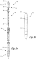
Figure 1a shows an exploded view of a catheter assembly according to an embodiment of the disclosure; -
Figure 1b shows a side view of the catheter assembly ofFigure 1 in a closed or sealed configuration; -
Figures 2a to 2c show the steps of removing the cap from the catheter assembly and stowing the cap on the opposing end of the catheter assembly external housing; -
Figure 3 shows a longitudinal section of the catheter assembly ofFigure 1 ; -
Figure 4 shows an enlarged longitudinal sectional view of the proximal end of the catheter assembly ofFigure 3 detailing a storage chamber and a wetting chamber; -
Figure 5 shows an enlarged longitudinal sectional view of the distal end of the catheter assembly ofFigure 3 ; -
Figures 6a to 6c show a sequence of longitudinal sections of the catheter assembly ofFigure 1 highlighting the wetting procedure for the catheter; -
Figure 7 show a perspective view of an internal housing which may be used in the catheter assembly ofFigure 1 ; -
Figures 8a and 8b show, respectively, a side view and flattened front view schematic of a plunger track provided by the internal housing ofFigure 7 ; -
Figures 9a to 9c show an upper portion of the internal housing and details of a cap which may be used with the catheter assembly shown inFigure 1 ; and -
Figures 10a to 10f show a sequence of side view images of the catheter assembly according to an embodiment of the invention demonstrating the principal steps for wetting and removing a catheter from the external housing. -
Figure 1 shows an axially exploded view of acatheter assembly 10 according to the present invention. The catheter assembly comprises anexternal housing 12, aninternal housing 14 and acatheter 16. Theexternal housing 12,internal housing 14 andcatheter 16 are concentrically arranged such that thecatheter 16 is located within theinternal housing 14 which is located within theexternal housing 12 in a radially nested configuration. - The
catheter assembly 10 may be configured such that thecatheter 16 may be wetted prior to being withdrawn from theexternal housing 12. The wetting agent used to wet thecatheter 16 prior to use and may be held in a wetting agent storage chamber which is defined between theexternal housing 12 and theinternal housing 14. The wetting agent may be delivered to thecatheter 16 via a wetting chamber which is defined between theinternal housing 14 and catheter. The wetting agent may be pumped or driven into the wetting chamber from the storage chamber. The wetting agent may be water or some other suitable agent, as well known in the art. - Referring to
Figures 1a, 1b ,3 ,4 and9b and 9c , theexternal housing 12 comprises amain body 18 in which a portion of theinternal housing 14 andcatheter 16 are housed, and acap 20 which is detachable so as to be removable by a user prior to use of the catheter. Removing thecap 20 may expose thecatheter 16 such that it can be withdrawn from theexternal housing 12. - The
external housing 12 provides an enclosed volume in which thecatheter 16 can be housed for storage and transportation prior to use. Themain body 18 andcap 20 may provide a sterile cavity in which thecatheter 16 is located. Theexternal housing 12 is generally elongate having alongitudinal axis 22 which can be taken to be the principal axis of thecatheter assembly 10 and also provide the longitudinal axis for theinternal housing 14 andcatheter 16 etc. References to a longitudinal axis, axial or radial in this disclosure should be taken to be with reference to thelongitudinal axis 22 unless stated otherwise. - The enclosed volume provided by the
external housing 12 is defined by an external wall of thehousing 12 which extends from a firstproximal end 13, which receives aninsertion end 24 of thecatheter 16, to a seconddistal end 15 in which acatheter outlet end 26 is received. In the embodiment shown, thesecond end 15 is provided by thecap 20. Thus, the removal of thecap 20 exposes the outlet end 26 of thecatheter 16 such that a user can grip and remove thecatheter 16 from thehousing 12 for use. - The external profile of the
housing 12 can be any required for aesthetic or functional purposes and, in the example shown, is generally cylindrical, tapering towards the first end to aid insertion into a storage receptacle or pocket, for example, and tapering towards the second end along the length of thecap 20. - The
cap 20 comprises an open-ended generally cylindrical enclosure having a circumferential external wall which extends coaxially along thelongitudinal axis 22, and a radially extending, axially facing end wall which provides a closed end at the terminal end of thecap 20 andexternal housing 12. Thecap 20 mates with the distal end of themain body 18, such that themain body 18 is received within an open end of thecap 20. However, it will be appreciated that thecap 20 could be received within an open end of the main body in some embodiments. - A hermetic seal may be provided between the
cap 20 andmain body 18 to preserve the sterility of the internal volume of theexternal housing 12, prior to use. The hermetic seal of the embodiment described comprises one or more (in this case two)internal seals Figures 3 and5 and described further below. Additionally/alternatively a hermetic seal may be provided by a tamper proof connection or strip between themain body 18 andcap 20. - The
external housing 12 may be used to transport thecatheter 16 ready for use and also to dispose of the catheter following use. In order to prevent thecap 20 being misplaced or separated from themain body 18 whilst thecatheter 16 is being used, and to avoid having an additional item to store in an environment which may not be conducive to hygienic storage (such as a public lavatory) thecap 20 may be temporarily mounted to themain body 18. Thus, thecap 20 may be removed from the open end of themain body 18 to expose thecatheter 16 for removal and use, and mounted on the closed end of themain body 18. Once thecatheter 16 has been used, it may be placed back within themain body 18 and thecap 20 re-connected with the open end of themain body 18 to enclose the usedcatheter 16 therein for disposal. - This process can be seen in
Figures 2a to 2c in whichFigure 2a shows acatheter assembly 10 in which cap 20 is detachably attached prior to use,Figure 2b shows thecap 20 being removed from themain body 18 and moved to the opposing end (as indicated by the arrows), andFigure 2c shows thecap 20 attached to the opposing end of the main body18. Thecatheter 16 is not shown but it will be appreciated that it would be exposed at the uppermost end of themain body 18 as shown, when present. - To enable the temporary mounting of the
cap 20 onto the closed end of themain body 18, the external surface of the closed end of themain body 18 and the inner surface of thecap 20 may comprise corresponding mating surfaces. These are indicated byreference 21 for themain body 18 inFigure 2a and reference numeral 21' inFigure 9c for thecap 20. The mating surfaces 21, 21' may be configured to provide an interference fit in which the frictional engagement between thecap 20 and closed end of themain body 18 is sufficient to temporarily retain thecap 20. The interference fit may be achieved by providing a suitably shaped, and in this embodiment suitably large contacting surface area between the inner surface of thecap 20 and outer surface of themain body 18. As such, an axial portion of the outer surface of themain body 18 may have a profile which corresponds to the inner surface of thecap 20. In the example shown inFigures 2a-2c , the profile may be a uniform taper in which the angle of the taper along the mating surface is constant, but other profiles are possible. - The
cap 20 and/ormain body 18 will generally be substantially rigid so as to provide protection for thecatheter 16 during transportation and to preserve integrity of the enclosed volume and maintain sterility. However, it will be appreciated that thecap 20 and/ormain body 18 may be sufficiently resilient to allow a small amount of deformation to assist with the interference fit between thecap 20 andmain body 18. - In addition, or alternatively, to the inner surface of the
cap 20 and the outer surface of themain body 18 having corresponding profiles, either or both of thecap 20 andmain body 18 may comprise mating surfaces 21, 21' comprising one or more formations which provide or enhance the interference fit and/or attachment of thecap 20 to themain body 18. For example, thecap 20 may be fitted to the closed end of themain body 18 using radial projections such as the ribs 286b described in relation to the embodiment of figure 15 below, using a click-fit engagement in which thecap 20 resiliently engages with one or more interlocking features such as a circumferentially extending rib or a number of circumferentially distributed pips. Providing a click-fit engagement may help provide users with feedback that thecap 20 has been securely attached. Alternatively or additionally, thecap 20 and/ormain body 18 may comprise one or more inserts, coatings (such as overmoulding with a softer material), liners, screw threads or other features which enhance one or more of the resilience, contacting surface area, coefficient of friction or engagement between thecap 20 andmain body 18. - The
main body 18 andcap 20 may be made from thermoplastics, for example polypropylene. Other polymers such as polycarbonate, polyethylene, or nylon could be used. Equally an overmoulded design where a softer material is utilised on the inside of the cap or a portion of the outside of the body may be used to aid with retention of the cap onto the body - The
cap 20 may be removed from themain body 18 in an axial direction prior to being inverted and located on the closed end of themain body 18 in the same axial direction. Thecap 20 may be pulled linearly off themain body 18, or may be rotated or twisted off, for example, where thecap 20 is attached via a screw thread for example. An example of ascrew thread Figures 9a and 9c . - Part or all of the internal surface of the
cap 20 may provide the mating surfaces 21'. The embodiment ofFigure 9c includes three portions which provide separate functions. The first portion is the mating surface 21' portion located distal-most and extending from the closed end towards open proximal end, ending partway along the internal length of thecap 20. A second portion includes ascrew thread 62a for engaging with aninternal housing 14 of thecatheter assembly 10, and the third portion provides anti-rotation features 60b, which are described further below. It will be appreciated that other configurations ofcap 20 are possible, and the provision and respective location of the various portions may differ in other embodiments. - As noted above, the profile of the
external housing 12 may be longitudinally tapered. The transverse cross-sectional profile of the external surface of thecap 20 may be any desired. The transverse cross-sectional profile may be round, for example, circular or oval. In some embodiments, the transverse profile may be polygonal such as triangular or square.Figure 9b shows an embodiment in which the external surface 20' of thecap 20 is a rounded square to aid user's grip for rotating thecap 20 during actuation and/or removal steps. - With reference to
Figures 1a ,3 and4 , themain body 18 may provide an enclosure which defines a reservoir for a wetting fluid (not shown). The reservoir is formed between themain body 18 and theinternal housing 14. Thus, theinternal housing 14 may be provided within theexternal housing 12 in a spaced relation so as to define acavity 28 therebetween. Thecavity 28 may be referred to as a wettingagent storage chamber 28, or simplystorage chamber 28 herein. Thestorage chamber 28 may comprise a first chamber wall provided by themain body 18 and a movable insert provided by theinternal housing 14. Theinternal housing 14 may therefore provide a second storage chamber wall. - The
storage chamber 28 is sealed in a first configuration such that the wetting agent is retained therein, and open in a second configuration such that the wetting agent can flow out of thecavity 28 so as to be in flow communication with and, in some embodiments, directly contact an external surface of thecatheter tube 32 of thecatheter 16. - When in the open configuration, the internal volume of the
storage chamber 28 may be in fluid communication with a wettingchamber 30 in which the catheter is located such that the wetting agent can flow from thestorage chamber 28 to the wettingchamber 30 andcatheter tube 32. In some embodiments, the fluid communication between thestorage chamber 28 and wettingchamber 30, may be via one or more valves, inlet channels, or intermediate chambers, such as a priming chamber for example. An example of a priming chamber is described further below. - As shown in
Figures 1a ,3 and4 , the enclosed volume of theexternal housing 12 may be partitioned by theinternal housing 14 which may be referred to as a movable insert. Theinternal housing 14 may comprise a tubular wall which is configured to define the wettingagent storage chamber 28 on a radially outer side thereof, and a wettingchamber 30 on a radially inner side thereof. - As shown best in
Figure 4 , theinternal housing 14 may comprise an elongate thin-walled structure which extends longitudinally along theprincipal axis 22 of thecatheter assembly 10. Theinternal housing 14 comprises a first end which is distal to the insertion end of thecatheter 16 and a second, proximal end which is proximal with respect to, and may surround, theinsertion end 24 of thecatheter 16. It will be appreciated that the length of theinternal housing 14 and the position of the respective distal and proximal ends of theinternal housing 14, as well as the separation from the external housing chamber wall, may be varied across embodiments and determined to provide a required volume for the wettingagent storage chamber 28. Further design considerations may arise where theinternal housing 14 is configured to act as a pump for pumping the wetting agent from thestorage chamber 28 and/or a priming chamber to the wetting chamber during a wetting procedure. - The wetting
chamber 30 comprises an elongate cavity between an internal surface of theinternal housing 14 and an external surface of thecatheter tube 32 such that a wetting agent (not shown) can be provided to the wettingchamber 30 for wetting the exterior surface of thecatheter tube 32 prior to use. The wettingchamber 30 may be fully or partially defined by an internal surface of theinternal housing 14 and/or an intermediate member such as asheath 34 which is located within theinternal housing 14 and which surrounds thecatheter tube 32 during a wetting procedure. - The
storage chamber 28 may be an elongate annular cavity which encircles thelongitudinal axis 22 andcatheter tube 32 and extends axially between a first distal end and a second proximal end. The cavity may be sealed at the first and second ends using one ormore seals seal elements surfaces internal housing 14 andexternal housing 12. Theseal elements internal housing 14 andmain body 18. - In order to open the
storage chamber 28, thecatheter assembly 10 may incorporate one or more valves which may be opened so as to fluidly connect thestorage chamber 28 and wettingchamber 30. The one or more valves may be operated by moving the movable insert, e.g. theinternal housing 14. The movable insert may be moved by direct manipulation from a user's hand, or by actuating thecap 20. For example, rotating or pulling thecap 20 may cause the one or more valves to open so as to fluidly connect thestorage chamber 28 and wettingchamber 30 such that wetting agent can flow from thestorage chamber 28 to the wettingchamber 30 and an external surface of thecatheter tube 32. The valve may be provided in part by theinternal housing 14. - The
internal housing 14 may be axially movable along theprincipal axis 22 of thecatheter assembly 10. The axial movement may induce an opening at one or more of theseals storage chamber 28 such that the opposingseal elements surfaces respective seals internal housing 14 from themain body 18 may cause the respective opposing surfaces'seal 36 to move axially in relation to one another and increase the separation of theinternal housing 14 andexternal housing 12 across theseal 36 which provides an opening. As such, one or more of theseals - The
seal 36 which is configured to act as a valve in this described embodiment may be located proximally such that wetting agent in thestorage chamber 28 can flow from the proximal end of thestorage chamber 28 into the closed end of themain body 18 of thehousing 12. This may be referred to as a priming chamber. From there, the fluid is provided in flow communication with exterior of thecatheter tube 32 either directly, or via one more inlets to the wettingchamber 30. - Also shown in
Figures 3 and4 is anoptional insertion guide 25. Theinsertion guide 25 is a short elongate annular cuff which resides around a proximal end of thecatheter tube 32. Thecatheter tube 32 is slidably received within theinsertion guide 25 such that theinsertion guide 25 can move distally when thecatheter tube 32 is being inserted. This is described in more detail below. - As noted above, the
storage chamber 28 is sealed by aproximal seal 36 and adistal seal 38 to provide an elongate annular cavity in which the wetting fluid can be stored away from thecatheter 16. Theseals seals internal housing 14 and theexternal housing 12. It will be appreciated that, more generally, thecatheter assembly 10 andstorage chamber 28 in particular may be provided with more than onedistal seal 38 orproximal seal 36 to provide the necessary sealing function. - One of the sealing surfaces may form part of a
seal housing seal element seal element seal housing seal external housing 12. In the example shown, theseal housings internal housing 14. Hence, theseal housing seal elements internal housing 14 relative to theexternal housing 12 allows theseal internal housing 14 along the opposing sealing surface of theexternal housing 12. It will be appreciated that the seal housing(s) 36d, 38d may be provided by theexternal housing 12 in some embodiments. - As noted above, the axial movement of the
seal 36 may expose or provide one or more outlets for allowing fluid communication between thestorage chamber 28 and wettingchamber 30. Additionally, one or more seals may open one or more vents. The vents may act as air inlets configured to allow gas to enter thestorage chamber 28 to replace the wetting agent as it exits thestorage chamber 28. The vents may be internal so as to open thestorage chamber 28 to another internal cavity, or external so as to draw air in directly from the exterior of theassembly 10. - As shown in the embodiment of
Figure 4 , theproximal seal 36 may be located adjacent adivergent portion 36c in thestorage chamber 28. The divergent portion corresponds to an increased separation between theexternal housing 12 and theinternal housing 14, which may be provided by a step or taper in the profile of the respective surface of theinternal housing 14 andexternal housing 12. Hence, aseal 36 of thestorage chamber 28 may be located at a local restriction between the opposing walls of thestorage chamber 28. - The divergent portion provides a space into which the
seal 36 can be moved when thestorage chamber 28 is opened. Hence, when theinternal housing 14 shown inFigure 4 is moved distally (so as to rise in the image as shown), theseal 36 moves into the wider chamber portion, thereby opening a flow path from thestorage chamber 28 into the proximal end of themain body 18. As such, theseal 36 operates as a valve and theinsertion end 24 of thecatheter 16 may be submerged in wetting agent which has flowed from thestorage chamber 28. As can be seen inFigure 4 , although both the internal housing wall and external housing wall comprise steps/tapered portions which contribute to the divergence of thestorage chamber 28, it is the wall which comprises the sealingsurface 36b against which theseal element 36a urges and moves against that provides the separation. - The
distal seal 38 of thestorage chamber 28 is axially spaced from theproximal seal 36 along theinternal housing 14 and provided in a fixed location relative to theproximal seal 36. Thedistal seal 38 may include aseal housing 38d similar to the one provided for theproximal seal 36 such that axial movement of theinternal housing 14 results a translation of theseal element 38a along the length of theexternal housing 12. Thedistal seal 38 in the embodiment ofFigure 4 differs from theproximal seal 36 in that the seal surfaces are substantially uniformly spaced and theseal surface 38b which opposes theseal housing 38d and the active sealing surface of theseal element 38a remains in contact with theseal element 38a upon displacement of theinternal housing 14. As such, thedistal seal 36 may remain in-tact as theinternal housing 14 is displaced and the proximate seal valve opened. As noted above, the axial movement of theproximal seal 38 may result in one or more vents being exposed and/or opened. - The
internal housing 14 may be configured to provide pump for pumping the wetting agent into the wettingchamber 30. As such, thedistal seal 38 may be configured to maintain a higher pressure thanproximal seal 36 which is configured to maintain the integrity of thestorage chamber 28 when the assembly is stored and transported prior to use. As can be seen inFigure 4 , thedistal seal element 38a may be larger than theproximal seal element 36a. - As can be seen from
Figure 5 , thedistal seal 38 of thestorage chamber 28 may be axially spaced from the open distal end of themain body 18. The extent of the distance may correspond to or be greater than the throw (axial movement) of theinternal housing 14 when undergoing a wetting or priming operation. Hence, following a full movement of theinternal housing 14, thedistal seal 38 may remain in contact with the wall of theexternal housing 12. -
Figure 7 shows an exploded view of an embodiment of theinternal housing 14 which comprises first 14a and second 14b parts joined together by ascrew threads 14c. It will be appreciated that the specific construction ofinternal housing 14 may vary and it may, in some embodiments, be provided by a unitary structure or parts which are joined using alternative methods, such as a push fit or bayonet construction. - As can be seen from
Figure 7 , one ormore vents 40 may be provided in the sidewall of theinternal housing 14. The one ormore vents 40 may provide an outlet for the wettingchamber 30 such that air displaced from the wettingchamber 30 when wetting agent flows up or into the wettingchamber 30 can escape. - In some embodiments, the opening of the
storage chamber 28 may be sufficient to wet the catheter, in which case, once the wettingchamber 28 has been opened, it may be sufficient to withdraw thecatheter 16 for use (optionally inverting the assembly between opening the chamber and withdrawing the catheter, in order to ensure adequate distribution of wetting agent). In some embodiments, the wetting procedure for wetting thecatheter 16 may include a pumping or plunging action in which wetting agent is pneumatically and/or hydraulically driven from thestorage chamber 28 into and along the wettingchamber 30. - In the embodiment shown in
Figure 1 , the pumping action may be provided by the axial movement of theinternal housing 14 within theexternal housing 12. Theinternal housing 12, acting as a movable insert, may be configured to move axially to reduce the volume of thestorage chamber 28 thereby pumping/driving a flow of the wetting agent into the proximal end and the wettingchamber 30 so as to wet the catheter. -
Figures 6a to 6c show a wetting operation of thecatheter assembly 10 in which theinternal housing 14 is moved distally and axially along thelongitudinal axis 22 from a first position to a second position resulting in an opening of thestorage chamber 28 and subsequent driving of the wetting agent distally along thecatheter tube 32.Figures 6a to 6c show the actuation of the assembly with thecap 20 place, however, it will be appreciated that this may not be the case in some embodiments and thecap 20 may be fully removed. Further, thecatheter assembly 10 is shown as being horizontal, but the assembly may be operated in a vertical orientation. - The wetting operation involves three primary phases. The first phase, shown in
Figure 6a is a closed or sealed configuration/position in which thecap 20 is retained on themain body 18 of thehousing 12 for storage and transportation purposes and thestorage chamber 28 is sealed and includes the wetting agent. InFigure 6b , thecap 20 is released from themain body 18 and theinternal housing 14 moved axially and distally via thecap 20 such that theproximal seal 36 element moves away from the opposing seal surface provided by themain body 18 and aflow path 42 opens to allow wettingagent 44 held in thestorage chamber 28 to be moved into the proximal end of themain body 18. This may be referred to as a priming phase or charging phase in which the wettingchamber 30, or an associatedpriming antechamber 46 is primed with the wetting agent ready to be driven along thecatheter tube 32.Figure 6b may be referred to as a priming configuration or priming position. - When the movable insert i.e. the internal housing, is in the primed position, it is to be noted that the
distal seal 38 maintains contact with the inner wall of themain body 18 such that the leakage of wetting agent from thestorage chamber 28 to the exterior of thecatheter assembly 10 is prevented. However, one or more vents may be provided at the distal end of thestorage chamber 28, configured to allow gaseous communication between thestorage chamber 28 and remainder of thecatheter assembly 10, when the internal housing is in the primed position, one or more channels arranged between thestorage chamber 28 and the vents are opened which allows gas (i.e. air) to enter the storage chamber to displace the wetting agent. Typically the assembly will be held vertically, or at least with the closed end of the main body lower than the cap, such that gravity assists in allowing wetting agent to move into the closed end of the main body and the priming chamber.Optional ribs 64 discussed below also assist in allowing wetting agent to move from thestorage chamber 28 to the priming chamber. - Once the wetting
agent 44 has moved into the closed end of themain body 18 and the priming chamber, theinternal housing 14 can be re-inserted into themain body 18 such that the wetting agent is forced upfluid path 48 via an inlet to the wettingchamber 30 between theinternal housing 14 andcatheter tube 32. Air displaced from the wettingchamber 30 can exit from a suitable outlet which exhausts the displaced air outside of the catheter assembly.Figures 6c and7 provide examples of suitable outlets in the form ofopenings 40 which are provided in the internal housing wall and located between the distal end of theinternal housing 14 and distal end of themain body 28 so as to be exposed externally. There are two diametricallyopposed openings 40 in the embodiment shown, however, there may be fewer or greater than twoopenings 40. It will be appreciated that the size, shape and position may also differ. Theopenings 40 shown in the embodiment are oval having a major axis extending circumferentially to allow a larger aperture for a reduced axial length. - The inlet to the wetting
chamber 30 from thestorage chamber 28/priming chamber 46 may be provided via the separation between theinternal housing 14 andcatheter tube 32. In the embodiment shown inFigures 6a to 6c , there is asheath 34 surrounding thecatheter tube 32 which may form and at least partially define the wettingchamber 30, or may be provided within the wetting chamber. In this case, the inlet to the wetting chamber may be provided between thecatheter tube 32 andsheath 34. Additionally, or alternatively, where aninsertion guide 25 is included, the inlet may be determined by the separation between theinsertion guide 25 andcatheter tube 32. In a further alternative, for example with nosheath 34, the wetting chamber may be at least partially formed and defined by the inner surface of theinternal housing 14. The inlet may be defined by the separation between the bottom end of theinternal housing 14 and thecatheter tube 32. - In some embodiments, the
internal housing 14 may be reciprocated upon rotation of the actuator and thus moved back and forth several times. However, it will typically be sufficient to undertake a single distal-proximal cycle to create a sufficient wetting of thecatheter tube 32, thereby using the internal housing as a plunger. - As noted above, the plunging action of the
internal housing 14 may be achieved by hand such that a user directly manipulates theinternal housing 14 distally and proximally along a linear axial path by pulling and pushing on theinternal housing 14 whilst restraining theexternal housing 12. However, in some embodiments it may be preferable to drive the movement of theinternal housing 14 with an actuator. - The actuator, which may be referred to as a priming mechanism, may be any device which can cause the required axial movement of the
internal housing 14. Theinternal housing 14 may be configured to move axially when rotated. In some embodiments, the actuator may comprise a cam-drive or crank in which rotational movement of theinternal housing 14 is used to drive the linear, axial motion of theinternal housing 14 relative to themain body 18. The rotational movement of theinternal housing 14 may be provided by a rotatable actuator in the form of arotating cap 20, for example. - In some embodiments, the rotation of the
cap 20 may be used to drive the linear movement of theinternal housing 14 and also to remove thecap 20 from themain body 18. Thus, the rotation of thecap 20 may comprise a first stage and a second stage. The first stage may correspond to the driving of theinternal housing 14 to open thestorage chamber 28 and to pump the wetting fluid around thecatheter tube 32. The second stage may correspond to the releasing of thecap 20 from themain body 18 to expose thecatheter 16 for use. - The simultaneous rotational and axial movement of the internal housing may be provided by one or more drive surfaces which are driven by a corresponding driving element. For example, the chamber wall provided by the external housing or the internal housing may comprise one or more axially and circumferentially extending drive surface. The other of the chamber wall and movable insert may comprise a driving element which engages with the drive surface to provide the axial movement of the movable insert upon relative rotation of the movable insert and chamber wall. The drive surface may comprise a first axially facing surface provided by a radially projecting flange, rib, thread, track or rail. The driving element may comprise a second axially facing surface of a radially extending flange, rib, thread, track, rail or pin. The drive surface and driving element may be referred to as a cam drive.
- An embodiment of an actuator/priming mechanism having a drive surface and driving element will now be described in connection with
Figures 7, 8a and 8b. Figure 7 shows a perspective exploded view of theinternal housing 14 which is described in part above.Figure 8a shows a side view of a drive surface in the form of a plunger track portion of the internal housing, andFigure 8b shows a schematic flattened front view of theplunger track 50 demonstrating a general shape a plunger track may have. -
Figure 7 shows a perspective view of theinternal housing 14 in which there is provided an elongate thin-walled enclosure havingrespective seal housings proximal seal 36 anddistal seal 38 of thestorage chamber 28 provided at opposing ends of thehousing 14. The external surface of theinternal housing 14 comprises a drive surface in the form of atrack 50, which may be referred to as a plunger track, which engages with a corresponding driving element 52 (Figure 8a ) appended to the external housing 12 (not shown). As shown, theplunger track 50 may include a channel which receives the drivingelement 52 in the form of a projection, e.g. a pin, which extends from an internal surface of theexternal housing 12, or an intermediate member. The channel may be provided by a pair of axially separated guide rails in the form of radially projectingwalls internal housing 14. Thewalls track 50 may comprise partial walls in accordance with the direction of actuation required. That is, where the internal housing is urged distally, only the distal wall may be required to provide the necessary drive surface, and vice versa. - It will be appreciated that, in some embodiments, the
track 50 may be provided on the interior surface of theexternal housing 12 and correspondingly the drivingelement 52 may be appended from the exterior of theinternal housing 14. It will also be appreciated that theplunger track 50 and drivingelement 52 may comprise any suitable features for allowing the necessary driving engagement which translates the rotational movement of theinternal housing 14 into an axial movement. Thus, thetrack 50 and drivingelement 52 may comprise any combination of a channels, grooves, ridges, protuberances, recesses, notches, bearings and gears, amongst others to provide the drive surface and driving element. - The
track 50 is provided proximally of thedistal seal 38 such that it is located within thestorage chamber 28. Providing theplunger track 50 within thestorage chamber 28 is optional and it may, in some embodiments be provided either distally or proximally of the distal 38 and proximal 36 seals. However, providing the plunger track within thestorage chamber 28 may allow the overall length of theassembly 10 to be shorter and may provide a convenient point to fill thestorage chamber 28 with wetting agent, as discussed further below. - In some embodiments, the
catheter assembly 10 may comprise a filling aperture in the external housing such that wetting agent can be introduced to thestorage chamber 28 once thecatheter assembly 10 has been assembled. Thus, the aperture may be provided in flow communication with thestorage chamber 28. Returning toFigure 4 , there is shown anaperture 52a which extends through the wall of theexternal housing 12, e.g. themain body 18, so as to provide access to the storage chamber externally to thecatheter assembly 10. Theaperture 52a may be configured to receive any suitable nozzle or attachment which is connected to a source of wetting agent and may be referred to as a port. It will be appreciated though that theaperture 52a may be a conventional round through-hole. - The positioning of the filling
aperture 52a in the described embodiment is such that it overlays thetrack 50, such that, following a filling procedure, the drivingpin 52 can be inserted (and optionally welded in place) to plug the fillingaperture 52a whilst extending into thetrack 50 so as to fulfil the function of a drivingelement 50. It will be appreciated that the filling aperture may simply be plugged in other embodiments and the plug may not provide a drivingelement 52 for the actuator for moving the movable insert. - As shown in
Figure 4 , although theinternal housing 14 is generally spaced from theexternal housing 12, theinternal housing 12 may be snugly received within theexternal housing 12 such that there is minimal clearance between the outer edge of thetrack 50 and/or ribs and the internal surface of theexternal housing 12. Providing a minimal clearance allows thetrack 50 and/orribs 64 to keep the internal housing concentric to the external housing when being moved. - To allow the wetting agent to flow from the
aperture 52a into thestorage chamber 28, the proximal rail of thetrack 50 may comprise a discontinuity, e.g. anaperture 52b, as can be seen schematically inFigure 7 . There may be a plurality of discontinuities so as to provide a 'hyphenated' guide rail. It will be appreciated that any aperture or discontinuity will typically be provided on a non-drive surface which does not require contact with the drivingelement 52 to actuate the axial movement of theinternal housing 14. In some embodiments, there may be no drive surface on the proximal side of the aperture, particularly where the reactive force for axially translating the movable insert is required on the distal side of the drivingelement 52. - As best seen in the schematic view of
Figure 8b , theplunger track 50 is elongate and extends from afirst endpoint 54 which corresponds to the closed configuration or position, to a mid-point 56 which corresponds to the primed configuration or position, to asecond endpoint 58 which corresponds to the post-plunged wetted configuration or position. Thetrack 50 may be generally cosine or U-shaped extending from thefirst end 54 at a distal-most location to thesecond point 56 at a proximal-most location to thethird point 58 at the distal-most location which is angularly (circumferentially) spaced from the first point. - The separation between the respective
adjacent points internal housing 14 as theinternal housing 14 is rotated. Thus, thesection 55 between thefirst end point 54 and mid-point 56 define, at least in part, the priming movement of theinternal housing 14 in which theproximal seal 36 is opened. Theend section 59 between the mid-point or primedposition 56 and second end point or post-plungedwetted position 58 corresponds to the pumping movement in which theinternal housing 14 is reinserted to drive the wetting agent from the priming chamber to the wettingchamber 30. Theintermediate section 57 corresponds to the primed position in which theinternal housing 14 extends out of theexternal housing 12 with the proximal seal open such that the wetting agent can flow into the primingchamber 56. - The
track 50 may be continually curved or comprise one or more straight portions. For example, as can be seen inFigure 8b , thetrack 50 comprises straight portions for the first 55 andfinal sections 59 which represent the majority of the transitions between the distal-most and proximal-most positions of theinternal housing 14. The lower portion of thetrack 50 is broadly flat with little to no axial displacement and so provides a dwell period in which theinternal housing 14 is rotated in the open configuration to provide sufficient time for the wetting fluid to drain from thestorage chamber 28 into the primingchamber 46 provided at the proximal end of themain body 18. - It will be appreciated that the term "straight portion" used above refers to the axial trajectory of the
track 50 as revealed by the front-on view taken when thetrack 50 is flattened out, as provided inFigure 8b . Thetrack 50 itself will continuously curve due to it extending circumferentially around thelongitudinal axis 22. - The terminal ends 54, 58 of the
track 50 may be provided with a change in trajectory such that the speed of the axial movement along thelongitudinal axis 22 may be reduced when the movement is commencing and terminating to provide an improved tactile experience for the user. That is, leading into the actuation and out of the actuation with a reduced acceleration and deceleration may provide a less abrupt start and finish to the actuation and provide an improved user experience. Moreover, a lower axial movement may offer a mechanical advantage as movement commences, against the resistance to axial movement caused by the seals. - In use, the
internal housing 14 is rotated such that the drivingelement 52 travels along thetrack 50. As the drivingelement 52 is held in a stationary relation to theexternal housing 12, rotation of theinternal housing 14 results in a linear movement along thelongitudinal axis 22 of thecatheter assembly 10. The initial phase of the movement in the proximally extending portion oftrack 50 results in a distal movement of theinternal housing 14 so as to open theproximal seal 36, as described above. From there, the drivingelement 52 enters therotation portion 57 in which thewetting agent 44 drains out of thestorage chamber 28 with a reduced amount of axial movement, which is then followed by thethird portion 57 of the track which drives the internal housing distally and towards the priming chamber. - The arrangement of the
track 50 is such that rotating theinternal housing 14 in a single direction for a predetermined angular extent, i.e. a given rotation of thecap 20, causes a full linear cycle of movement. The predetermined angular extent may be any which is considered appropriate for thecap 20 and user experience. - The terminal end of the
track 58 is provided with a closed end such that further rotation of the internal housing is not possible once the drivingelement 52 contacts the closed end. As such, the actuator may be provided with a mechanical stop or rotational limiter which limits the rotation of the internal housing. This can provide mechanical feedback to the user to indicate that the priming and/or wetting phase of the catheter has been achieved and the catheter can be removed. Following the mechanical feedback, thecap 50 can be removed andcatheter 16 withdrawn for use. - It will be appreciated that the extent of the rotation will determine the amount of force required to move the internal housing. Thus, a short angular extent, for example 90 degrees, will result in a faster movement of the internal housing and will require a greater force when compared with a longer rotation of, for example, 270 degrees. The range of angular movement may be between 90 degrees and 360 degrees.
- In embodiments where the rotation of the
internal housing 14 relative to themain body 18 is achieved via thecap 20, thecap 20 and/or internal housing may comprise one or more interlocks to rotationally engage thecap 20 andinternal housing 14. There may be a plurality of interlocks which may be distributed circumferentially about thecap 20 on the internal surface thereof. - Referring to
Figures 9a to 9c , it can be seen that an interlock may be provided byrespective interengaging projections 60a on an external surface of theinternal housing 14 which are received within correspondingrecesses 60b in the internal surface of thecap 20. As can be seen, there may be a plurality ofinterlocks 60a,b evenly distributed about the periphery of thecap 20 andinternal housing 14 to provide multiple points of engagement. The embodiment shows four interlocks, however, there may be greater than or fewer than this. Therecesses 60b are shown as being provided in the thicker section of thecap 20 wall so as to maintain a minimal thickness at the proximal edge and provide the necessary the hoop strength. However, this is not a limitation and therecesses 60b may be provided in different or other circumferential locations. - The
interlocks 60a,b may comprise a torque activated release such that, upon reaching a predetermined threshold of rotating torque on the cap, the interlocks release allowing thecap 20 to rotate relative to theinternal housing 14. Thus, once the travel of the drivingelement 52 reaches the end of the drive surface and engages the rotational limiter, an increased torque and continued rotation of thecap 20 overcomes the interlocks and allows thecap 20 to rotate relative to theinternal housing 14. Once released, the further rotation of thecap 20 may allow thecap 20 to be removed. - To provide the torque activated release, the interlocks may comprise shapes which are configured to disengage beyond a given torque. The shape of the
projections 60a and recesses 60b may correspond to one another such that the surfaces of therecesses 60b are provided in intimate contact with theprojections 60a. When viewed in plan, it can be seen that the contacting surfaces are inclined relative to the tangent at the respective locations such that the projections are triangular. Providing tangentially inclined surfaces contacting surfaces in this way provides a convenient way to control the torque threshold the interlocks can withstand before releasing, allowing the interlocks to release when the drivingelement 52 reaches theterminal end 58 of theplunger track 50. - The
recesses 60b andprojections 60a may be configured to prevent rotational separation only, with axial engagement between theinternal housing 14 andcap 20 being provided by other features. Hence, as shown inFigure 9c , therecesses 60b may be provided in the proximal edge of thecap 20 adjacent to the open end. This provides therecesses 60b with an open end along the axial direction. - To prevent the
cap 20 being pulled axially off theinternal housing 14 in a distal direction, thecap 20 and/orinternal housing 14 may comprise an axial retention feature which retains the relative axial position with theinternal housing 14 whilst thecap 20 is being rotated. In the described embodiment, the axial retention feature is provided by ascrew thread 62a which engages with ascrew thread 62b on an external surface of theinternal housing 14. The screw thread may be used to remove thecap 20 from theinternal housing 14 once the plunging action is complete and the torque threshold has been overcome. Removing thecap 20 from the screw thread may expose the catheter for a user to handle. - The
screw threads 62a,b may comprise partial turn or full turn threads. The partial turn threads may comprise, for example, a quarter turn thread in which thecap 20 is removed following a quarter turn of thecap 20 following the rotational disengagement from theinternal housing 14. - As noted above, the rotation of the
cap 20 may comprise a plurality of stages. The rotation of thecap 20 may comprise a priming step and a removal step. The priming step and removal step may be sequential and be achieved by rotating thecap 20 in the same rotational direction. The sum of the first and second steps may correspond to the number or turns required to remove the wet the catheter and remove thecap 20. For example, a full 360 degree rotation of thecap 20 may result in the wetting and removal of thecap 20. The wetting phase may comprise a 270 degrees, or three-quarter turn and the removal of thecap 20 may comprise a further quarter turn. Other combinations of turns and turn steps may be possible. - The driving element may comprise a plug which is received within a filling orifice of the
storage chamber 28. Thus, themain body 18 may comprise at least one aperture extending through an external wall thereof, the aperture providing access to the internal volume of thestorage chamber 28 such that the wetting fluid may be received via the aperture. The aperture may be configured to receive the driving element/plug 52 following the filling procedure. Thus, the aperture may oppose thefirst end 54 of the track. - The internal volume of the catheter assembly may be sterilised following assembly. In order to preserve the sterility of the internal volume the catheter assembly may comprise a hermetic seal. The hermetic seal may comprise an external surface of the catheter assembly or may comprise one or more seals located within the
cap 20 and/ormain body 18. The hermetic seal may be broken by rotation of the cap relative to the main body. Returning toFigure 5 , there are shownhermetic seals main body 18 andcap 20. Theseals - The
hermetic seals cap 20 is removed from themain body 18. Thus, rotating thecap 20 to initiate transitioning from the sealed configuration to the primed configuration may break (i.e. open) theseal internal housing 14 is moved distally with the rotation of thecap 20, theseal 68 will open initially, thereby breaking the hermetic seal before thecap 20 is actually separated from the internal housing. However, thedistal seal 38 will prevent the wetting agent leaving the distal end of the storage chamber, thereby rendering the catheter assembly in a primed by leak-resistant configuration. This is advantageous as it allows thecatheter assembly 10 to be left temporarily once primed such that a user might put the catheter aside for a short time once opened, for example, to adjust position and/or clothing (or even for longer, to answer the door, say, before returning to catheterisation) prior to removing the catheter from the external housing. - Returning to
Figure 7 , it can be seen that theinternal housing 14 may be provided withoptional ribs 64. Theribs 64 may be included to maintain the separation of theinternal housing 14 andexternal housing 12 which defines thestorage chamber 28. Hence, whenribs 64 may assist in guiding theinternal housing 14 when moved axially and rotationally. Theribs 64 may also aid with the pumping action of theinternal housing 14 when it is reinserted into theexternal housing 12. Thus, theribs 64 may act to drive the wetting agent proximally into the closed end and up the wettingchamber 30. - The
ribs 64 may extend circumferentially around theinternal housing 14. Theribs 64 may be discontinuous in the circumferential direction such that a flow path may be maintained betweenadjacent ribs 64. As can be seen, theribs 64 may be provided along the length of theinternal housing 14. In the embodiment shown there are three sets ofribs 64 disposed at regular intervals along the length of theinternal housing 14. Each set ofribs 64 includes four separate circumferential sub-ribs provide at common axial locations above a circumferential line with the ribs having the same angular length. It will be appreciated that the specific arrangement of the ribs may vary in other embodiments. - The sequential priming, wetting and cap removal rotation is shown in
Figures 10a to 10f which show the major steps for removing a catheter from an embodiment catheter assembly. -
Figure 10a shows thecatheter assembly 10 in a closed, pre-activation configuration in which the hermetic seal is intact and the interior cavity of theexternal housing 12 is sterile.Figure 10b shows a first step in which thecap 20 is turned through an initial rotation phase. The initial rotation of thecap 20 rotates theinternal housing 14 via the rotational engagement provided by theinterlocks internal housing 14 causes the drive surface provided bytrack 50 and drivingelement 52 to move theinternal housing 14 in an axially distal direction, together with thecap 20. As can be seen inFigure 10c , the distal movement of theinternal housing 14 opens thehermetic seal 68 and theproximal seal element 36a transitions of the divergent portion so as to open a flow path for the wetting agent, as seen inFigure 10d . At this point, the wetting agent flows into the primingchamber 44 at the proximal end of themain body 18 and the catheter assembly is primed. A continued rotation of thecap 20, moves theinternal housing 14 back into themain body 18 at which point theribs 64 pump the wetting agent from the primingchamber 44 up the wetting chamber inlet provided between the internal housing and insertion guide (if present) and thecatheter tube 32. Once the drivingelement 52 reaches the end of the drive surface provided bytrack 50, further rotation is not possible without an increase of torque. Thus, the user is provided with some mechanical feedback that thecatheter 16 has been wetted. The above actions are carried out with a single user action, i.e. the rotation of thecap 20 in a common direction using a substantially constant torque. - Following this first rotational step of the
cap 20, thecap 20 is further rotated releasing the torque activated release interlock thereby allowing thecap 20 to move relative to theinternal housing 12 via thethreads 62a,b. Following the removal of thecap 20, thecatheter 16 may be grasped by the external handling surfaces on the outlet end 26 of thecatheter 16 and withdrawn axially, ready for use. Where asheath 34 has been employed, this will be in a deployed position with thecatheter 16 located therein to preserve the sterility thereof during manipulation. - Referring to
Figures 1 and3 , thecatheter 16 may be any suitable catheter known in the art. As shown, thecatheter 16 may comprise acatheter tube 32, and afunnel 26. - The
catheter tube 32 may be an elongate thin-walled structure which extends longitudinally along theprincipal axis 22 of thecatheter assembly 10. Thecatheter tube 32 may be comprised of a flexible material. A first end of thecatheter tube 32 may be closed with a hemi-spherical cap, and form theinsertion end 24 of thecatheter 16, the hemispherical shape aiding with insertion. - Proximate to the
insertion end 24 there may be provided one or more drainage apertures 33, in this embodiment the drainage apertures 33 are oval in shape with the major axis being parallel with theprincipal axis 22. It will be appreciated that the size and shape of the drainage apertures 33 may differ. - The exterior surface of the
catheter tube 32 may be, as is known in the art, functionalised. such that when wetted by the wetting agent the co-efficient of friction of thecatheter tube 32 is reduced. The outer surface of thecatheter tube 32 may be comprised of, or coated in, a functionalising material; for example the outer surface of thecatheter tube 32 may have hydrophilic properties. The hydrophilic properties serve to reduce the coefficient of friction of the outer surface when the wetting agent is introduced. - The end of the
catheter 16 distal to theinsertion end 24 is provided with acatheter outlet end 26. In this embodiment thecatheter outlet end 26 is provided as afunnel 26 and is a separate component to the catheter tube, in other embodiments they may be integrally formed. The funnel is cylindrical in shape having a first open end and a second open end. The first open end is configured to receive thecatheter tube 32 by the end distal to theinsertion end 24. Thecatheter 16 is configured to provide fluid communication between the drainage apertures 33 and thecatheter outlet end 26. - Projecting radially from the exterior surface of the
funnel 26 there may be one or more projecting ribs. In the embodiment ofFigure 4 there are provided two projecting ribs; thefirst rib 35a is arranged proximate to the second end of the funnel and thesecond rib 35b is arranged between thefirst rib 35a and the first end of the funnel. Thesecond rib 35b is sized such that its external diameter corresponds to the internal diameter of the distal end of theinternal housing 14. Thefirst rib 35a is sized such that its external diameter is greater than the internal diameter of the distal end of theinternal housing 14 and less than the internal diameter of the open end of thecap 20. The arrangement of the two projectingribs 35a,b may be provided to maintain the position of thecatheter 16 relative to theinternal housing 14; thesecond rib 35b ensuring thecatheter 16 andinternal housing 14 are arranged coaxially, and thefirst rib 35a limiting the extent to which thecatheter 16 can be inserted into theinternal housing 14 proximally along theprincipal axis 22. - A region of the exterior surface of the funnel between the second end of the funnel and the
first rib 35a may be textured to provide a gripping surface for a user. Where the exterior surface of the funnel between the second end of the funnel and thefirst rib 35a is used as a gripping surface, the projecting ribs 35 fulfil an additional function, providing separation between a user's fingers and the (wetted)catheter tube 32. - As noted above,
Figures 1 and3 also show anoptional sheath 34. The sheath is formed of a flexible material and is arranged surrounding thecatheter tube 32. The sheath is coupled at a first end to the funnel proximate to the first open end thereof, and at a second end to theinsertion guide 25. Theinsertion guide 25, or part thereof, is comprised of an elastically deformable material. - In use, after completing the wetting cycle and removing the
cap 20, a user withdraws the wettedcatheter 16 from thecatheter assembly 10. Holding the gripping surface of thefunnel 26 and where present, theinsertion guide 25, the user directs thecatheter tube 32 into a canal, vessel, passageway, body cavity, etc. for removal of fluid therefrom. - Where the
sheath 34 and insertion guide 25 are present, the user grips theinsertion guide 25 to guide thecatheter tube 32. The user squeezes theinsertion guide 25, deforming it such that it engages with thecatheter tube 32, restricting axial motion of thecatheter tube 32 through theinsertion guide 25 and inserts a first section of thecatheter tube 32 exposed from within thesheath 34 into the canal, vessel, passageway, body cavity etc. Once the first section of thecatheter tube 32 has been inserted, the user relaxed their grip on theinsertion guide 25, allowing it to return to its original shape, and slidably draws theinsertion guide 25 along thecatheter tube 16 away from theinsertion end 24, furling a portion of thesheath 34 and exposing a second section of thecatheter tube 16. The process is then repeated, with the user squeezing theinsertion guide 25 to restrict the motion of theinsertion guide 25 with respect to thecatheter tube 16 and the second section of the catheter tube inserted. The process is repeated until the catheter tube is inserted sufficiently into the canal, vessel, passageway, body cavity etc. - The one or more embodiments are described above by way of example only. Many variations are possible without departing from the scope of protection afforded by the appended claims.
- For example, whilst the embodiment is a female intermittent urinary catheters, with an exemplary length of between 90mm to 200mm. e.g. between 130mm and 155mm, such as about 135mm and the catheter assemblies have a length corresponding to the length of the catheter, such as a closed length of the casing of between 2mm and 10mm longer than the length of catheter (e.g. 10-25cm; between 140mm and 165mm, such as 142mm), it is considered that teachings could be applied to male urinary intermittent catheters (which are typically longer) or even other types of catheter. Similarly, although the embodiments have functionalised hydrophilic surfaces which become slippery when wetted with a wetting agent such as water, the wetting agent could be a lubricant instead.
Claims (15)
- A catheter assembly (10) having a longitudinal axis (22), the catheter assembly comprising:a catheter (16); and,a wetting agent storage chamber (28), the wetting agent storage chamber comprising a chamber wall (18) and a movable insert (14),wherein the movable insert (14) is movable axially along the longitudinal axis (22) with respect to the chamber wall (18) between a first position and a second position, wherein in the first position the storage chamber (28) is sealed by a seal element (36a) located between the chamber wall (18) and the movable insert (14) wherein the seal element is a proximal seal element (36a) which is proximate to an insertion end of the catheter;the seal element (36a) is aligned with sealing surfaces (36b) of the chamber wall (18) and the movable insert (14) in the first position;and wherein in the second position the seal (36a) is axially misaligned with at least one of the sealing surfaces (36b); and whereinthe catheter assembly further comprises: a second seal element (38a) which is axially separated from the proximal seal element (36a) on the distal side thereof, thereby providing a distal seal element (38a).
- The catheter assembly (10) of claim 1, wherein at least one of the movable insert (14) and the chamber wall (18) comprises a divergent portion (36c) over which the seal element (36a) passes when transitioning between the first position and second position such that the distance between the chamber wall (18) and movable insert (14) at the axial location of the seal element is increased when in the second position.
- The catheter assembly of claim 2, wherein the divergent portion comprises (36c) a step or chamfer adjacent to the sealing surface.
- The catheter assembly (10) of any preceding claim wherein the catheter (16) is coaxially nested within with the storage chamber wall (18).
- The catheter assembly (10) of any preceding claim, wherein the movable insert (14) is configured to move with respect to the chamber wall (18) to a third position in which the catheter (16) is wetted with a wetting agent.
- The catheter assembly (10) of any preceding claim, further comprising a wetting chamber (30), wherein the catheter (16) is coaxially nested within the wetting chamber (30).
- The catheter assembly (10) of claim 6, further comprising a priming chamber (46), the priming chamber (46) being in flow series with the storage chamber (28) and wetting chamber (30).
- The catheter assembly of either of claims 6 or 7, wherein the storage chamber (28) and wetting chamber (30) are separate chambers.
- The catheter assembly (10) of any preceding claim, wherein, when in the second position, the seal element (36a) is separated from at least one of the sealing surfaces (36b) so as to provide a flow path for a wetting agent past the seal element (36a).
- The catheter assembly (10) of any preceding claim, wherein the distal seal element (38a) and proximal seal element (36a) are located radially between the movable insert (14) and the chamber wall (18).
- The catheter assembly (10) of any preceding claim, wherein the distal seal (38) maintains sealing contact in the first and second positions.
- The catheter assembly (10) according to any of claims 6 to 9, further comprising a pump (64) configured to pump a wetting agent into the wetting chamber (30).
- The catheter assembly (10) according to claim 12, wherein movable insert (14) comprises the pump (64).
- The catheter assembly (10) according to claim 13, wherein the movable insert (18) is movable from the second position to the first position to pump the wetting agent into the wetting chamber (30).
- The catheter assembly (10) of any preceding claim, further comprising an actuator to move the movable insert (14) relative to the chamber wall (18), wherein the actuator comprises a rotatable actuator (20) wherein rotation of the rotatable actuator (2) is converted into the axial movement between the movable insert (14) and the chamber wall (18).
Priority Applications (1)
| Application Number | Priority Date | Filing Date | Title |
|---|---|---|---|
| EP23216079.6A EP4311567A3 (en) | 2021-04-23 | 2022-04-22 | Intermittent catheter |
Applications Claiming Priority (2)
| Application Number | Priority Date | Filing Date | Title |
|---|---|---|---|
| GBGB2105819.3A GB202105819D0 (en) | 2021-04-23 | 2021-04-23 | Intermittent catheter |
| PCT/GB2022/051011 WO2022223979A1 (en) | 2021-04-23 | 2022-04-22 | Intermittent catheter |
Related Child Applications (1)
| Application Number | Title | Priority Date | Filing Date |
|---|---|---|---|
| EP23216079.6A Division EP4311567A3 (en) | 2021-04-23 | 2022-04-22 | Intermittent catheter |
Publications (3)
| Publication Number | Publication Date |
|---|---|
| EP4100092A1 EP4100092A1 (en) | 2022-12-14 |
| EP4100092C0 EP4100092C0 (en) | 2023-12-20 |
| EP4100092B1 true EP4100092B1 (en) | 2023-12-20 |
Family
ID=76193510
Family Applications (2)
| Application Number | Title | Priority Date | Filing Date |
|---|---|---|---|
| EP23216079.6A Pending EP4311567A3 (en) | 2021-04-23 | 2022-04-22 | Intermittent catheter |
| EP22721425.1A Active EP4100092B1 (en) | 2021-04-23 | 2022-04-22 | Intermittent catheter |
Family Applications Before (1)
| Application Number | Title | Priority Date | Filing Date |
|---|---|---|---|
| EP23216079.6A Pending EP4311567A3 (en) | 2021-04-23 | 2022-04-22 | Intermittent catheter |
Country Status (9)
| Country | Link |
|---|---|
| US (1) | US20230075906A1 (en) |
| EP (2) | EP4311567A3 (en) |
| JP (1) | JP7834112B2 (en) |
| CN (1) | CN117279686A (en) |
| AU (1) | AU2022262283A1 (en) |
| CA (1) | CA3216452A1 (en) |
| GB (1) | GB202105819D0 (en) |
| PL (1) | PL4100092T3 (en) |
| WO (1) | WO2022223979A1 (en) |
Families Citing this family (12)
| Publication number | Priority date | Publication date | Assignee | Title |
|---|---|---|---|---|
| US12589218B2 (en) | 2020-08-03 | 2026-03-31 | C. R. Bard, Inc. | Intermittent-catheter assembly and methods thereof |
| CN116322871A (en) | 2020-09-11 | 2023-06-23 | C·R·巴德股份有限公司 | Intermittent catheter assembly and method |
| US12594399B2 (en) | 2021-04-12 | 2026-04-07 | Convatec Limited | Catheter |
| GB202105820D0 (en) * | 2021-04-23 | 2021-06-09 | Convatec Ltd | Intermittent catheter |
| USD1089636S1 (en) | 2022-10-07 | 2025-08-19 | Coloplast A/S | Male straight urinary catheter |
| USD1084304S1 (en) * | 2022-10-07 | 2025-07-15 | Coloplast A/S | Female urinary catheter |
| USD1086447S1 (en) * | 2022-10-07 | 2025-07-29 | Coloplast A/S | Urinary catheter assembly |
| WO2024150005A1 (en) | 2023-01-12 | 2024-07-18 | Convatec Limited | Catheters |
| WO2024150007A1 (en) | 2023-01-12 | 2024-07-18 | Convatec Limited | Catheters |
| EP4680317A1 (en) * | 2023-03-17 | 2026-01-21 | ConvaTec Limited | Intermittent catheter |
| WO2024201079A1 (en) | 2023-03-29 | 2024-10-03 | Convatec Limited | Catheters |
| WO2026013408A1 (en) | 2024-07-11 | 2026-01-15 | Convatec Limited | Urinary catheters |
Family Cites Families (14)
| Publication number | Priority date | Publication date | Assignee | Title |
|---|---|---|---|---|
| DK147397A (en) * | 1997-12-17 | 1999-06-25 | Coloplast As | Ready-to-use urinary catheter device |
| CA2599195A1 (en) | 2005-03-03 | 2006-09-08 | Coloplast A/S | A package for a medical device |
| US7571804B2 (en) * | 2005-03-03 | 2009-08-11 | Coloplast A/S | Package for a medical device |
| WO2011019359A1 (en) | 2009-08-13 | 2011-02-17 | C. R. Bard, Inc. | Catheter having internal hydrating fluid storage and/or catheter package using the same and method of making and/or using the same |
| US9271855B2 (en) * | 2012-05-09 | 2016-03-01 | Abbott Cardiovascular Systems Inc. | Catheter having hydraulic actuator with tandem chambers |
| US9931486B2 (en) * | 2013-03-08 | 2018-04-03 | Coyloplast A/S | Catheter assembly |
| CA2904514C (en) * | 2013-03-14 | 2022-06-14 | Hollister Incorporated | Compact urinary catheters and methods for making the same |
| CN103301551B (en) * | 2013-06-09 | 2015-06-03 | 广州维力医疗器械股份有限公司 | Wetting component for hydrophilic urinary catheter |
| JP2018521802A (en) * | 2015-08-05 | 2018-08-09 | コーニンクレッカ フィリップス エヌ ヴェKoninklijke Philips N.V. | Catheter assembly with low axial sliding friction |
| EP3478897B1 (en) | 2016-06-30 | 2025-07-02 | Knauf Gips KG | Drywall construction system with spring rail |
| US10912918B1 (en) * | 2020-03-23 | 2021-02-09 | Cure Medical Llc | Pre-lubricated female urinary catheter package |
| GB202105817D0 (en) * | 2021-04-23 | 2021-06-09 | Convatec Ltd | Intermittent catheter |
| GB202105824D0 (en) * | 2021-04-23 | 2021-06-09 | Convatec Ltd | Intermittent catheter |
| GB202105822D0 (en) * | 2021-04-23 | 2021-06-09 | Convatec Ltd | Intermittent catheter |
-
2021
- 2021-04-23 GB GBGB2105819.3A patent/GB202105819D0/en not_active Ceased
-
2022
- 2022-04-22 EP EP23216079.6A patent/EP4311567A3/en active Pending
- 2022-04-22 JP JP2023564446A patent/JP7834112B2/en active Active
- 2022-04-22 AU AU2022262283A patent/AU2022262283A1/en active Pending
- 2022-04-22 PL PL22721425.1T patent/PL4100092T3/en unknown
- 2022-04-22 EP EP22721425.1A patent/EP4100092B1/en active Active
- 2022-04-22 CA CA3216452A patent/CA3216452A1/en active Pending
- 2022-04-22 WO PCT/GB2022/051011 patent/WO2022223979A1/en not_active Ceased
- 2022-04-22 CN CN202280030375.5A patent/CN117279686A/en active Pending
- 2022-09-13 US US17/943,250 patent/US20230075906A1/en active Pending
Also Published As
| Publication number | Publication date |
|---|---|
| JP2024518891A (en) | 2024-05-08 |
| CA3216452A1 (en) | 2022-10-27 |
| PL4100092T3 (en) | 2024-06-24 |
| WO2022223979A1 (en) | 2022-10-27 |
| GB202105819D0 (en) | 2021-06-09 |
| JP7834112B2 (en) | 2026-03-23 |
| CN117279686A (en) | 2023-12-22 |
| EP4100092A1 (en) | 2022-12-14 |
| EP4100092C0 (en) | 2023-12-20 |
| EP4311567A3 (en) | 2024-05-01 |
| US20230075906A1 (en) | 2023-03-09 |
| AU2022262283A1 (en) | 2023-10-05 |
| EP4311567A2 (en) | 2024-01-31 |
Similar Documents
| Publication | Publication Date | Title |
|---|---|---|
| EP4311567A2 (en) | Intermittent catheter | |
| US20240050692A1 (en) | Intermittent catheter | |
| US12076499B2 (en) | Intermittent catheter | |
| US12515015B2 (en) | Intermittent catheter | |
| US12623050B2 (en) | Intermittent catheter | |
| US12144934B2 (en) | Intermittent catheter | |
| US12156972B2 (en) | Intermittent catheter | |
| US20230077075A1 (en) | Intermittent catheter | |
| EP4608486A1 (en) | Intermittent catheter |
Legal Events
| Date | Code | Title | Description |
|---|---|---|---|
| STAA | Information on the status of an ep patent application or granted ep patent |
Free format text: STATUS: UNKNOWN |
|
| STAA | Information on the status of an ep patent application or granted ep patent |
Free format text: STATUS: THE INTERNATIONAL PUBLICATION HAS BEEN MADE |
|
| PUAI | Public reference made under article 153(3) epc to a published international application that has entered the european phase |
Free format text: ORIGINAL CODE: 0009012 |
|
| STAA | Information on the status of an ep patent application or granted ep patent |
Free format text: STATUS: REQUEST FOR EXAMINATION WAS MADE |
|
| 17P | Request for examination filed |
Effective date: 20220905 |
|
| AK | Designated contracting states |
Kind code of ref document: A1 Designated state(s): AL AT BE BG CH CY CZ DE DK EE ES FI FR GB GR HR HU IE IS IT LI LT LU LV MC MK MT NL NO PL PT RO RS SE SI SK SM TR |
|
| STAA | Information on the status of an ep patent application or granted ep patent |
Free format text: STATUS: EXAMINATION IS IN PROGRESS |
|
| 17Q | First examination report despatched |
Effective date: 20230120 |
|
| GRAP | Despatch of communication of intention to grant a patent |
Free format text: ORIGINAL CODE: EPIDOSNIGR1 |
|
| STAA | Information on the status of an ep patent application or granted ep patent |
Free format text: STATUS: GRANT OF PATENT IS INTENDED |
|
| RIC1 | Information provided on ipc code assigned before grant |
Ipc: A61M 27/00 20060101ALN20230622BHEP Ipc: A61M 25/00 20060101AFI20230622BHEP |
|
| DAV | Request for validation of the european patent (deleted) | ||
| DAX | Request for extension of the european patent (deleted) | ||
| RIC1 | Information provided on ipc code assigned before grant |
Ipc: A61M 27/00 20060101ALN20230705BHEP Ipc: A61M 25/00 20060101AFI20230705BHEP |
|
| INTG | Intention to grant announced |
Effective date: 20230726 |
|
| RIC1 | Information provided on ipc code assigned before grant |
Ipc: A61M 27/00 20060101ALN20230718BHEP Ipc: A61M 25/00 20060101AFI20230718BHEP |
|
| GRAJ | Information related to disapproval of communication of intention to grant by the applicant or resumption of examination proceedings by the epo deleted |
Free format text: ORIGINAL CODE: EPIDOSDIGR1 |
|
| GRAS | Grant fee paid |
Free format text: ORIGINAL CODE: EPIDOSNIGR3 |
|
| GRAA | (expected) grant |
Free format text: ORIGINAL CODE: 0009210 |
|
| STAA | Information on the status of an ep patent application or granted ep patent |
Free format text: STATUS: THE PATENT HAS BEEN GRANTED |
|
| AK | Designated contracting states |
Kind code of ref document: B1 Designated state(s): AL AT BE BG CH CY CZ DE DK EE ES FI FR GB GR HR HU IE IS IT LI LT LU LV MC MK MT NL NO PL PT RO RS SE SI SK SM TR |
|
| INTG | Intention to grant announced |
Effective date: 20230726 |
|
| REG | Reference to a national code |
Ref country code: GB Ref legal event code: FG4D |
|
| REG | Reference to a national code |
Ref country code: CH Ref legal event code: EP |
|
| REG | Reference to a national code |
Ref country code: DE Ref legal event code: R096 Ref document number: 602022001404 Country of ref document: DE |
|
| REG | Reference to a national code |
Ref country code: IE Ref legal event code: FG4D |
|
| U01 | Request for unitary effect filed |
Effective date: 20231220 |
|
| U07 | Unitary effect registered |
Designated state(s): AT BE BG DE DK EE FI FR IT LT LU LV MT NL PT SE SI Effective date: 20240105 |
|
| PG25 | Lapsed in a contracting state [announced via postgrant information from national office to epo] |
Ref country code: GR Free format text: LAPSE BECAUSE OF FAILURE TO SUBMIT A TRANSLATION OF THE DESCRIPTION OR TO PAY THE FEE WITHIN THE PRESCRIBED TIME-LIMIT Effective date: 20240321 |
|
| U20 | Renewal fee for the european patent with unitary effect paid |
Year of fee payment: 3 Effective date: 20240320 |
|
| PG25 | Lapsed in a contracting state [announced via postgrant information from national office to epo] |
Ref country code: ES Free format text: LAPSE BECAUSE OF FAILURE TO SUBMIT A TRANSLATION OF THE DESCRIPTION OR TO PAY THE FEE WITHIN THE PRESCRIBED TIME-LIMIT Effective date: 20231220 |
|
| PG25 | Lapsed in a contracting state [announced via postgrant information from national office to epo] |
Ref country code: GR Free format text: LAPSE BECAUSE OF FAILURE TO SUBMIT A TRANSLATION OF THE DESCRIPTION OR TO PAY THE FEE WITHIN THE PRESCRIBED TIME-LIMIT Effective date: 20240321 Ref country code: ES Free format text: LAPSE BECAUSE OF FAILURE TO SUBMIT A TRANSLATION OF THE DESCRIPTION OR TO PAY THE FEE WITHIN THE PRESCRIBED TIME-LIMIT Effective date: 20231220 |
|
| PG25 | Lapsed in a contracting state [announced via postgrant information from national office to epo] |
Ref country code: RS Free format text: LAPSE BECAUSE OF FAILURE TO SUBMIT A TRANSLATION OF THE DESCRIPTION OR TO PAY THE FEE WITHIN THE PRESCRIBED TIME-LIMIT Effective date: 20231220 Ref country code: NO Free format text: LAPSE BECAUSE OF FAILURE TO SUBMIT A TRANSLATION OF THE DESCRIPTION OR TO PAY THE FEE WITHIN THE PRESCRIBED TIME-LIMIT Effective date: 20240320 Ref country code: HR Free format text: LAPSE BECAUSE OF FAILURE TO SUBMIT A TRANSLATION OF THE DESCRIPTION OR TO PAY THE FEE WITHIN THE PRESCRIBED TIME-LIMIT Effective date: 20231220 |
|
| PG25 | Lapsed in a contracting state [announced via postgrant information from national office to epo] |
Ref country code: IS Free format text: LAPSE BECAUSE OF FAILURE TO SUBMIT A TRANSLATION OF THE DESCRIPTION OR TO PAY THE FEE WITHIN THE PRESCRIBED TIME-LIMIT Effective date: 20240420 |
|
| PG25 | Lapsed in a contracting state [announced via postgrant information from national office to epo] |
Ref country code: CZ Free format text: LAPSE BECAUSE OF FAILURE TO SUBMIT A TRANSLATION OF THE DESCRIPTION OR TO PAY THE FEE WITHIN THE PRESCRIBED TIME-LIMIT Effective date: 20231220 |
|
| PG25 | Lapsed in a contracting state [announced via postgrant information from national office to epo] |
Ref country code: SK Free format text: LAPSE BECAUSE OF FAILURE TO SUBMIT A TRANSLATION OF THE DESCRIPTION OR TO PAY THE FEE WITHIN THE PRESCRIBED TIME-LIMIT Effective date: 20231220 |
|
| PG25 | Lapsed in a contracting state [announced via postgrant information from national office to epo] |
Ref country code: SM Free format text: LAPSE BECAUSE OF FAILURE TO SUBMIT A TRANSLATION OF THE DESCRIPTION OR TO PAY THE FEE WITHIN THE PRESCRIBED TIME-LIMIT Effective date: 20231220 Ref country code: SK Free format text: LAPSE BECAUSE OF FAILURE TO SUBMIT A TRANSLATION OF THE DESCRIPTION OR TO PAY THE FEE WITHIN THE PRESCRIBED TIME-LIMIT Effective date: 20231220 Ref country code: RO Free format text: LAPSE BECAUSE OF FAILURE TO SUBMIT A TRANSLATION OF THE DESCRIPTION OR TO PAY THE FEE WITHIN THE PRESCRIBED TIME-LIMIT Effective date: 20231220 Ref country code: IS Free format text: LAPSE BECAUSE OF FAILURE TO SUBMIT A TRANSLATION OF THE DESCRIPTION OR TO PAY THE FEE WITHIN THE PRESCRIBED TIME-LIMIT Effective date: 20240420 Ref country code: CZ Free format text: LAPSE BECAUSE OF FAILURE TO SUBMIT A TRANSLATION OF THE DESCRIPTION OR TO PAY THE FEE WITHIN THE PRESCRIBED TIME-LIMIT Effective date: 20231220 |
|
| REG | Reference to a national code |
Ref country code: DE Ref legal event code: R097 Ref document number: 602022001404 Country of ref document: DE |
|
| PLBE | No opposition filed within time limit |
Free format text: ORIGINAL CODE: 0009261 |
|
| STAA | Information on the status of an ep patent application or granted ep patent |
Free format text: STATUS: NO OPPOSITION FILED WITHIN TIME LIMIT |
|
| PG25 | Lapsed in a contracting state [announced via postgrant information from national office to epo] |
Ref country code: MC Free format text: LAPSE BECAUSE OF FAILURE TO SUBMIT A TRANSLATION OF THE DESCRIPTION OR TO PAY THE FEE WITHIN THE PRESCRIBED TIME-LIMIT Effective date: 20231220 |
|
| 26N | No opposition filed |
Effective date: 20240923 |
|
| PG25 | Lapsed in a contracting state [announced via postgrant information from national office to epo] |
Ref country code: MC Free format text: LAPSE BECAUSE OF FAILURE TO SUBMIT A TRANSLATION OF THE DESCRIPTION OR TO PAY THE FEE WITHIN THE PRESCRIBED TIME-LIMIT Effective date: 20231220 |
|
| PG25 | Lapsed in a contracting state [announced via postgrant information from national office to epo] |
Ref country code: IE Free format text: LAPSE BECAUSE OF NON-PAYMENT OF DUE FEES Effective date: 20240422 |
|
| U20 | Renewal fee for the european patent with unitary effect paid |
Year of fee payment: 4 Effective date: 20250319 |
|
| PG25 | Lapsed in a contracting state [announced via postgrant information from national office to epo] |
Ref country code: CY Free format text: LAPSE BECAUSE OF FAILURE TO SUBMIT A TRANSLATION OF THE DESCRIPTION OR TO PAY THE FEE WITHIN THE PRESCRIBED TIME-LIMIT; INVALID AB INITIO Effective date: 20220422 |
|
| PG25 | Lapsed in a contracting state [announced via postgrant information from national office to epo] |
Ref country code: HU Free format text: LAPSE BECAUSE OF FAILURE TO SUBMIT A TRANSLATION OF THE DESCRIPTION OR TO PAY THE FEE WITHIN THE PRESCRIBED TIME-LIMIT; INVALID AB INITIO Effective date: 20220422 |
|
| REG | Reference to a national code |
Ref country code: CH Ref legal event code: H13 Free format text: ST27 STATUS EVENT CODE: U-0-0-H10-H13 (AS PROVIDED BY THE NATIONAL OFFICE) Effective date: 20251125 |
|
| PG25 | Lapsed in a contracting state [announced via postgrant information from national office to epo] |
Ref country code: CH Free format text: LAPSE BECAUSE OF NON-PAYMENT OF DUE FEES Effective date: 20250430 |
|
| PGFP | Annual fee paid to national office [announced via postgrant information from national office to epo] |
Ref country code: GB Payment date: 20260319 Year of fee payment: 5 |
|
| PGFP | Annual fee paid to national office [announced via postgrant information from national office to epo] |
Ref country code: PL Payment date: 20260327 Year of fee payment: 5 |
|
| U20 | Renewal fee for the european patent with unitary effect paid |
Year of fee payment: 5 Effective date: 20260319 |