EP4099556A1 - Resonant frequency tracking for zero voltage switching - Google Patents
Resonant frequency tracking for zero voltage switching Download PDFInfo
- Publication number
- EP4099556A1 EP4099556A1 EP22175670.3A EP22175670A EP4099556A1 EP 4099556 A1 EP4099556 A1 EP 4099556A1 EP 22175670 A EP22175670 A EP 22175670A EP 4099556 A1 EP4099556 A1 EP 4099556A1
- Authority
- EP
- European Patent Office
- Prior art keywords
- voltage
- inverter
- zero
- current
- module
- Prior art date
- Legal status (The legal status is an assumption and is not a legal conclusion. Google has not performed a legal analysis and makes no representation as to the accuracy of the status listed.)
- Pending
Links
Images



Classifications
-
- H—ELECTRICITY
- H02—GENERATION; CONVERSION OR DISTRIBUTION OF ELECTRIC POWER
- H02M—APPARATUS FOR CONVERSION BETWEEN AC AND AC, BETWEEN AC AND DC, OR BETWEEN DC AND DC, AND FOR USE WITH MAINS OR SIMILAR POWER SUPPLY SYSTEMS; CONVERSION OF DC OR AC INPUT POWER INTO SURGE OUTPUT POWER; CONTROL OR REGULATION THEREOF
- H02M1/00—Details of apparatus for conversion
- H02M1/08—Circuits specially adapted for the generation of control voltages for semiconductor devices incorporated in static converters
- H02M1/083—Circuits specially adapted for the generation of control voltages for semiconductor devices incorporated in static converters for the ignition at the zero crossing of the voltage or the current
-
- H—ELECTRICITY
- H02—GENERATION; CONVERSION OR DISTRIBUTION OF ELECTRIC POWER
- H02M—APPARATUS FOR CONVERSION BETWEEN AC AND AC, BETWEEN AC AND DC, OR BETWEEN DC AND DC, AND FOR USE WITH MAINS OR SIMILAR POWER SUPPLY SYSTEMS; CONVERSION OF DC OR AC INPUT POWER INTO SURGE OUTPUT POWER; CONTROL OR REGULATION THEREOF
- H02M7/00—Conversion of AC power input into DC power output; Conversion of DC power input into AC power output
- H02M7/42—Conversion of DC power input into AC power output without possibility of reversal
- H02M7/44—Conversion of DC power input into AC power output without possibility of reversal by static converters
- H02M7/48—Conversion of DC power input into AC power output without possibility of reversal by static converters using discharge tubes with control electrode or semiconductor devices with control electrode
- H02M7/4815—Resonant converters
-
- A—HUMAN NECESSITIES
- A61—MEDICAL OR VETERINARY SCIENCE; HYGIENE
- A61L—METHODS OR APPARATUS FOR STERILISING MATERIALS OR OBJECTS IN GENERAL; DISINFECTION, STERILISATION OR DEODORISATION OF AIR; CHEMICAL ASPECTS OF BANDAGES, DRESSINGS, ABSORBENT PADS OR SURGICAL ARTICLES; MATERIALS FOR BANDAGES, DRESSINGS, ABSORBENT PADS OR SURGICAL ARTICLES
- A61L2/00—Disinfection or sterilisation of materials or objects, in general; Accessories therefor
- A61L2/02—Disinfection or sterilisation of materials or objects, in general; Accessories therefor using physical processes
- A61L2/08—Radiation
- A61L2/10—Ultraviolet [UV] radiation
-
- A—HUMAN NECESSITIES
- A61—MEDICAL OR VETERINARY SCIENCE; HYGIENE
- A61L—METHODS OR APPARATUS FOR STERILISING MATERIALS OR OBJECTS IN GENERAL; DISINFECTION, STERILISATION OR DEODORISATION OF AIR; CHEMICAL ASPECTS OF BANDAGES, DRESSINGS, ABSORBENT PADS OR SURGICAL ARTICLES; MATERIALS FOR BANDAGES, DRESSINGS, ABSORBENT PADS OR SURGICAL ARTICLES
- A61L2/00—Disinfection or sterilisation of materials or objects, in general; Accessories therefor
- A61L2/24—Apparatus using programmed or automatic operation
-
- A—HUMAN NECESSITIES
- A61—MEDICAL OR VETERINARY SCIENCE; HYGIENE
- A61L—METHODS OR APPARATUS FOR STERILISING MATERIALS OR OBJECTS IN GENERAL; DISINFECTION, STERILISATION OR DEODORISATION OF AIR; CHEMICAL ASPECTS OF BANDAGES, DRESSINGS, ABSORBENT PADS OR SURGICAL ARTICLES; MATERIALS FOR BANDAGES, DRESSINGS, ABSORBENT PADS OR SURGICAL ARTICLES
- A61L2/00—Disinfection or sterilisation of materials or objects, in general; Accessories therefor
- A61L2/26—Accessories
-
- B—PERFORMING OPERATIONS; TRANSPORTING
- B64—AIRCRAFT; AVIATION; COSMONAUTICS
- B64D—EQUIPMENT FOR FITTING IN OR TO AIRCRAFT; FLIGHT SUITS; PARACHUTES; ARRANGEMENT OR MOUNTING OF POWER PLANTS OR PROPULSION TRANSMISSIONS IN AIRCRAFT
- B64D47/00—Equipment not otherwise provided for
- B64D47/02—Arrangements or adaptations of signal or lighting devices
-
- H—ELECTRICITY
- H02—GENERATION; CONVERSION OR DISTRIBUTION OF ELECTRIC POWER
- H02M—APPARATUS FOR CONVERSION BETWEEN AC AND AC, BETWEEN AC AND DC, OR BETWEEN DC AND DC, AND FOR USE WITH MAINS OR SIMILAR POWER SUPPLY SYSTEMS; CONVERSION OF DC OR AC INPUT POWER INTO SURGE OUTPUT POWER; CONTROL OR REGULATION THEREOF
- H02M1/00—Details of apparatus for conversion
- H02M1/0048—Circuits or arrangements for reducing losses
- H02M1/0054—Transistor switching losses
- H02M1/0058—Transistor switching losses by employing soft switching techniques, i.e. commutation of transistors when applied voltage is zero or when current flow is zero
-
- H—ELECTRICITY
- H05—ELECTRIC TECHNIQUES NOT OTHERWISE PROVIDED FOR
- H05B—ELECTRIC HEATING; ELECTRIC LIGHT SOURCES NOT OTHERWISE PROVIDED FOR; CIRCUIT ARRANGEMENTS FOR ELECTRIC LIGHT SOURCES, IN GENERAL
- H05B41/00—Circuit arrangements or apparatus for igniting or operating discharge lamps
- H05B41/14—Circuit arrangements
- H05B41/36—Controlling
-
- A—HUMAN NECESSITIES
- A61—MEDICAL OR VETERINARY SCIENCE; HYGIENE
- A61L—METHODS OR APPARATUS FOR STERILISING MATERIALS OR OBJECTS IN GENERAL; DISINFECTION, STERILISATION OR DEODORISATION OF AIR; CHEMICAL ASPECTS OF BANDAGES, DRESSINGS, ABSORBENT PADS OR SURGICAL ARTICLES; MATERIALS FOR BANDAGES, DRESSINGS, ABSORBENT PADS OR SURGICAL ARTICLES
- A61L2103/00—Materials or objects being the target of disinfection or sterilisation
- A61L2103/75—Room floors or walls
-
- A—HUMAN NECESSITIES
- A61—MEDICAL OR VETERINARY SCIENCE; HYGIENE
- A61L—METHODS OR APPARATUS FOR STERILISING MATERIALS OR OBJECTS IN GENERAL; DISINFECTION, STERILISATION OR DEODORISATION OF AIR; CHEMICAL ASPECTS OF BANDAGES, DRESSINGS, ABSORBENT PADS OR SURGICAL ARTICLES; MATERIALS FOR BANDAGES, DRESSINGS, ABSORBENT PADS OR SURGICAL ARTICLES
- A61L2202/00—Aspects relating to methods or apparatus for disinfecting or sterilising materials or objects
- A61L2202/10—Apparatus features
- A61L2202/11—Apparatus for generating biocidal substances, e.g. vaporisers, UV lamps
-
- A—HUMAN NECESSITIES
- A61—MEDICAL OR VETERINARY SCIENCE; HYGIENE
- A61L—METHODS OR APPARATUS FOR STERILISING MATERIALS OR OBJECTS IN GENERAL; DISINFECTION, STERILISATION OR DEODORISATION OF AIR; CHEMICAL ASPECTS OF BANDAGES, DRESSINGS, ABSORBENT PADS OR SURGICAL ARTICLES; MATERIALS FOR BANDAGES, DRESSINGS, ABSORBENT PADS OR SURGICAL ARTICLES
- A61L2202/00—Aspects relating to methods or apparatus for disinfecting or sterilising materials or objects
- A61L2202/10—Apparatus features
- A61L2202/14—Means for controlling sterilisation processes, data processing, presentation and storage means, e.g. sensors, controllers, programs
-
- H—ELECTRICITY
- H01—ELECTRIC ELEMENTS
- H01J—ELECTRIC DISCHARGE TUBES OR DISCHARGE LAMPS
- H01J61/00—Gas-discharge or vapour-discharge lamps
- H01J61/02—Details
- H01J61/12—Selection of substances for gas fillings; Specified operating pressure or temperature
-
- H—ELECTRICITY
- H02—GENERATION; CONVERSION OR DISTRIBUTION OF ELECTRIC POWER
- H02M—APPARATUS FOR CONVERSION BETWEEN AC AND AC, BETWEEN AC AND DC, OR BETWEEN DC AND DC, AND FOR USE WITH MAINS OR SIMILAR POWER SUPPLY SYSTEMS; CONVERSION OF DC OR AC INPUT POWER INTO SURGE OUTPUT POWER; CONTROL OR REGULATION THEREOF
- H02M7/00—Conversion of AC power input into DC power output; Conversion of DC power input into AC power output
- H02M7/003—Constructional details, e.g. physical layout, assembly, wiring or busbar connections
-
- H—ELECTRICITY
- H02—GENERATION; CONVERSION OR DISTRIBUTION OF ELECTRIC POWER
- H02M—APPARATUS FOR CONVERSION BETWEEN AC AND AC, BETWEEN AC AND DC, OR BETWEEN DC AND DC, AND FOR USE WITH MAINS OR SIMILAR POWER SUPPLY SYSTEMS; CONVERSION OF DC OR AC INPUT POWER INTO SURGE OUTPUT POWER; CONTROL OR REGULATION THEREOF
- H02M7/00—Conversion of AC power input into DC power output; Conversion of DC power input into AC power output
- H02M7/42—Conversion of DC power input into AC power output without possibility of reversal
- H02M7/44—Conversion of DC power input into AC power output without possibility of reversal by static converters
- H02M7/48—Conversion of DC power input into AC power output without possibility of reversal by static converters using discharge tubes with control electrode or semiconductor devices with control electrode
- H02M7/53—Conversion of DC power input into AC power output without possibility of reversal by static converters using discharge tubes with control electrode or semiconductor devices with control electrode using devices of a triode or transistor type requiring continuous application of a control signal
- H02M7/537—Conversion of DC power input into AC power output without possibility of reversal by static converters using discharge tubes with control electrode or semiconductor devices with control electrode using devices of a triode or transistor type requiring continuous application of a control signal using semiconductor devices only, e.g. single switched pulse inverters
- H02M7/5387—Conversion of DC power input into AC power output without possibility of reversal by static converters using discharge tubes with control electrode or semiconductor devices with control electrode using devices of a triode or transistor type requiring continuous application of a control signal using semiconductor devices only, e.g. single switched pulse inverters in a bridge configuration
- H02M7/53871—Conversion of DC power input into AC power output without possibility of reversal by static converters using discharge tubes with control electrode or semiconductor devices with control electrode using devices of a triode or transistor type requiring continuous application of a control signal using semiconductor devices only, e.g. single switched pulse inverters in a bridge configuration with automatic control of output voltage or current
-
- H—ELECTRICITY
- H03—ELECTRONIC CIRCUITRY
- H03L—AUTOMATIC CONTROL, STARTING, SYNCHRONISATION OR STABILISATION OF GENERATORS OF ELECTRONIC OSCILLATIONS OR PULSES
- H03L7/00—Automatic control of frequency or phase; Synchronisation
- H03L7/06—Automatic control of frequency or phase; Synchronisation using a reference signal applied to a frequency- or phase-locked loop
- H03L7/08—Details of the phase-locked loop
- H03L7/085—Details of the phase-locked loop concerning mainly the frequency- or phase-detection arrangement including the filtering or amplification of its output signal
-
- Y—GENERAL TAGGING OF NEW TECHNOLOGICAL DEVELOPMENTS; GENERAL TAGGING OF CROSS-SECTIONAL TECHNOLOGIES SPANNING OVER SEVERAL SECTIONS OF THE IPC; TECHNICAL SUBJECTS COVERED BY FORMER USPC CROSS-REFERENCE ART COLLECTIONS [XRACs] AND DIGESTS
- Y02—TECHNOLOGIES OR APPLICATIONS FOR MITIGATION OR ADAPTATION AGAINST CLIMATE CHANGE
- Y02B—CLIMATE CHANGE MITIGATION TECHNOLOGIES RELATED TO BUILDINGS, e.g. HOUSING, HOUSE APPLIANCES OR RELATED END-USER APPLICATIONS
- Y02B20/00—Energy efficient lighting technologies, e.g. halogen lamps or gas discharge lamps
-
- Y—GENERAL TAGGING OF NEW TECHNOLOGICAL DEVELOPMENTS; GENERAL TAGGING OF CROSS-SECTIONAL TECHNOLOGIES SPANNING OVER SEVERAL SECTIONS OF THE IPC; TECHNICAL SUBJECTS COVERED BY FORMER USPC CROSS-REFERENCE ART COLLECTIONS [XRACs] AND DIGESTS
- Y02—TECHNOLOGIES OR APPLICATIONS FOR MITIGATION OR ADAPTATION AGAINST CLIMATE CHANGE
- Y02B—CLIMATE CHANGE MITIGATION TECHNOLOGIES RELATED TO BUILDINGS, e.g. HOUSING, HOUSE APPLIANCES OR RELATED END-USER APPLICATIONS
- Y02B70/00—Technologies for an efficient end-user side electric power management and consumption
- Y02B70/10—Technologies improving the efficiency by using switched-mode power supplies [SMPS], i.e. efficient power electronics conversion e.g. power factor correction or reduction of losses in power supplies or efficient standby modes
Definitions
- the present disclosure relates to systems and methods for controlling a zero voltage switching (ZVS) power signal used to power an excimer lamp for use in aviation systems.
- ZVS zero voltage switching
- UV light has been found to be an effective disinfectant. Of the various UV wavelengths, 222 nanometers (222 nm) has been found to be particularly promising (effective and relatively safe for humans in moderate doses).
- 222 nanometers 222 nm
- Conventional power supplies for these excimer bulbs experience significant limitations, such changing electrical properties of the excimer bulb as it is used. As a result of these changing electrical properties, the resonant frequency of the excimer bulb changes, which may result in failure of zero voltage switching used to provide the power signal. The output voltage may thus become distorted as a result. Also, relatively high current may be output at the resonant frequency point, resulting in system power loss.
- the system includes a voltage zero crossing detection module configured to detect a zero voltage condition in response to an inverter voltage from a resonant inverter crossing zero volts.
- the system further includes a current zero crossing detection module configured to detect a zero current condition in response to an inverter current from the resonant inverter crossing zero amps.
- the system further includes a phase detect module configured to detect actual phase data corresponding to an actual phase angle between the inverter voltage and the inverter current based on the zero voltage condition and the zero current condition.
- the system further includes a comparator configured to determine a phase difference between a desired phase between the inverter voltage and the inverter current and the actual phase angle.
- the system further includes a controller configured to adjust a property of a resonant inverter to reduce the phase difference based on the phase difference.
- the phase detect module includes: a voltage phase locked loop (PLL) module that receives voltage input corresponding to the zero voltage condition from the voltage zero crossing detection module; and a current PLL module that receives current input corresponding to the zero current condition from the current zero crossing detection module.
- PLL voltage phase locked loop
- any of the foregoing embodiments may further include an and module configured to receive an output of the voltage PLL module and an output of the current PLL module and to output an output signal in response to the output of the voltage PLL module and the output of the current PLL module both being true, wherein: the voltage PLL module further receives the output signal of the and module; the current PLL module further receives the output signal of the and module; and the actual phase data determined by the phase detect module is taken as the output of the voltage PLL module.
- Any of the foregoing embodiments may further include a low pass filter configured to receive the actual phase data from the phase detect module and to output a constant value corresponding to the actual phase angle.
- Any of the foregoing embodiments may further include a bias generator configured to receive the constant value corresponding to the actual phase angle and to output a biased phase angle to be used by the comparator as the actual phase angle.
- Any of the foregoing embodiments may further include an angle reference module configured to compare deadtime data and matching inductor data and to output the desired phase.
- the controller is a proportional-integral-derivative (PID) controller configured to receive the phase difference and to output a controller signal to be used by the resonant inverter to reduce the phase difference.
- PID proportional-integral-derivative
- the resonant inverter includes a plurality of switches
- the controller signal corresponds to control of the plurality of switches of the resonant inverter.
- the power signal is configured for use by an excimer bulb.
- the system is configured for use on an aircraft.
- the system includes a resonant inverter having at least one switch and configured to output an inverter voltage and an inverter current.
- the system further includes a voltage zero crossing detection module configured to detect a zero voltage condition in response to the inverter voltage crossing zero volts.
- the system further includes a current zero crossing detection module configured to detect a zero current condition in response to the inverter current crossing zero amps.
- the system further includes a phase detect module configured to detect actual phase data corresponding to an actual phase angle between the inverter voltage and the inverter current based on the zero voltage condition and the zero current condition.
- the system further includes a comparator configured to determine a phase difference between a desired phase between the inverter voltage and the inverter current and the actual phase angle.
- the system further includes a controller configured to adjust a property of the at least one switch of the resonant inverter to reduce the phase difference based on the phase difference.
- the phase detect module includes: a voltage phase locked loop (PLL) module that receives voltage input corresponding to the zero voltage condition from the voltage zero crossing detection module; and a current PLL module that receives current input corresponding to the zero current condition from the current zero crossing detection module.
- PLL voltage phase locked loop
- any of the foregoing embodiments may further include an and module configured to receive an output of the voltage PLL module and an output of the current PLL module and to output an output signal in response to the output of the voltage PLL module and the output of the current PLL module both being true, wherein: the voltage PLL module further receives the output signal of the and module; the current PLL module further receives the output signal of the and module; and the actual phase data determined by the phase detect module is taken as the output of the voltage PLL module.
- any of the foregoing embodiments may further include: a low pass filter configured to receive the actual phase data from the phase detect module and to output a constant value corresponding to the actual phase angle; and a bias generator configured to receive the constant value corresponding to the actual phase angle and to output a biased phase angle to be used by the comparator as the actual phase angle.
- the method includes detecting, by a voltage zero crossing detection module, a zero voltage condition in response to an inverter voltage from a resonant inverter crossing zero volts.
- the method further includes detecting, by current zero crossing detection module, a zero current condition in response to an inverter current from the resonant inverter crossing zero amps.
- the method further includes detecting, by a phase detect module, actual phase data corresponding to an actual phase angle between the inverter voltage and the inverter current based on the zero voltage condition and the zero current condition.
- the method further includes determining, by a comparator, a phase difference between a desired phase between the inverter voltage and the inverter current and the actual phase angle.
- the method further includes adjusting, by a controller, a property of a resonant inverter to reduce the phase difference based on the phase difference.
- Any of the foregoing embodiments may further include filtering, by a low pass filter, the actual phase data to output a constant value corresponding to the actual phase angle.
- Any of the foregoing embodiments may further include outputting, by a bias generator, a based phase angle to be used by the comparator as the actual phase angle based on the constant value from the low pass filter.
- Any of the foregoing embodiments may further include comparing, by an angle reference module, deadline data and matching inductor data to determine the desired phase.
- the property of the resonant inverter corresponds to at least one switch of the resonant inverter.
- the power signal is configured for use by an excimer bulb on an aircraft.
- any reference to singular includes plural embodiments, and any reference to more than one component or step may include a singular embodiment or step.
- any reference to attached, fixed, connected or the like may include permanent, removable, temporary, partial, full and/or any other possible attachment option.
- any reference to without contact (or similar phrases) may also include reduced contact or minimal contact. Surface shading lines may be used throughout the figures to denote different parts but not necessarily to denote the same or different materials.
- the present disclosure is directed to a new system and method for controlling an excimer lamp in aviation applications.
- the concept relates to a resonant frequency tracking and adjusting approach for zero voltage switching (ZVS) under a parameter change of the excimer lamp.
- the system calculates a phase angle using a phase locked loop (PLL).
- a bias generator determines a leading and lagging status.
- the output may be used as a feedback signal for the ZVS and resonant frequency tracking control.
- the angle present value (based on deadtime value and inductor value) may be calculated and used as a reference for ZVS and resonant frequency tracking.
- the reference is the phase angle and the range may be within negative 3 decibels.
- the phase angle error is calculated.
- a proportional-integral-derivative (PID) controller may adjust a pulse-width modulation (PWM) count value.
- PWM pulse-width modulation
- a portion of an aircraft lavatory 100 may include one or more UV excimer bulb 102.
- the excimer bulb 102 may emit UV light towards a portion of the lavatory 100, as shown by an arrow 106.
- the lavatory 100 may further include a power supply 104 designed to provide a power signal to the excimer bulb 102.
- the power supply 104 may provide a relatively high voltage power signal (i.e., between 500 volts and 3 kilovolts (3 kV), between 1 kV and 3 kV, or between 1.5 kV and 2.5 kV).
- the power supply 104 may be designed to receive either direct current (DC) input power or alternating current (AC) input power, and may output an AC output power signal.
- the power supply 104 may be designed to provide a desirable power signal to the excimer bulb 102 regardless of a status of the excimer bulb 102. That is, over time, the excimer bulb 102 may degrade and may have changing electrical properties as a result (e.g., a resistance or capacitance of the excimer bulb 102 may change over time).
- the power supply 104 is designed to compensate for these changing electrical properties of the excimer bulb 102.
- the power supply 104 may include a power circuit 300 and a controller 301.
- the power circuit 300 may include a bridge circuit 302 having one or more switch located therein, such as a transistor or any other switching circuit element.
- the bridge circuit 302 may receive an input voltage 306 and may generate a desirable waveform to control the excimer lamp 102 by controlling the switches.
- the power circuit 300 may function as a resonant inverter.
- the controller 301 may control operation of the switches in the bridge circuit 302 based on various parameters, as described in more detail below.
- the power circuit 300 may further include an inductor 304 which is used to match a resonant frequency of the excimer lamp 102. The output from the inductor 304 and the bridge circuit 302 may be used to power the excimer lamp 102.
- the power circuit 300 may include any circuit with one or more switching element that can output power signals having a frequency usable to power the excimer lamp 102.
- the controller 301 may include one or more logic devices such as one or more of a central processing unit (CPU), an accelerated processing unit (APU), a digital signal processor (DSP), a field programmable gate array (FPGA), an application specific integrated circuit (ASIC), or the like.
- the controller 301 may further include any non-transitory memory known in the art.
- the memory may store instructions usable by the logic device to perform operations.
- the memory may also or instead store other data as instructed by the controller 301 such as calculated or desired phase angles.
- the controller 301 may include various modules that perform specific functions.
- the functions of the modules may be implemented in hardware (e.g., transistors, logic gates, etc.), firmware, software, or any combination thereof.
- the controller 301 may include a phase angle calculation module 202 that calculates a phase angle between an input voltage (i.e., the voltage across the excimer lamp 102 in FIG. 3A ) and an input current (i.e., the current flowing through the inductor 304).
- the controller 301 may further include a ZVS control and resonant frequency tracking module 204 outputs a signal usable to control the switch(es) of the power circuit 300.
- the phase angle calculation module 202 may include a voltage zero crossing detection module 206 and a current zero crossing detection module 208.
- the voltage zero crossing detection module 206 may receive an inverter voltage signal 210 from a resonant inverter (e.g., the power circuit 300) and may detect a zero voltage condition corresponding to the inverter voltage signal 210 crossing zero volts. That is, the inverter voltage signal 210 may have a frequency and may alternate between positive and negative voltage values, and the voltage zero crossing detection module 206 may detect when the inverter voltage signal 210 reaches zero volts when switching from positive to negative or from negative to positive.
- the current zero crossing detection module 208 may receive an inverter current signal 212 from the resonant inverter and may detect a zero current condition corresponding to the inverter current signal 212 crossing zero volts.
- the voltage zero crossing detection module 206 may output a zero voltage signal 214 corresponding to the zero voltage condition detection.
- the current zero crossing detection module 208 may output a zero current signal 216 corresponding to the zero current condition.
- a phase detect module 218 may receive the zero voltage signal 214 and the zero current signal 216 corresponding to the zero voltage condition and the zero current condition.
- the phase detect module 218 may detect or determine actual phase data 226 corresponding to an actual phase angle between the inverter voltage signal 210 and the inverter current signal 212 based on the zero voltage signal 214 and the zero current signal 216.
- the phase detect module 218 may include a voltage phase locked loop (PLL) module 220 that receives the zero voltage signal 214, and a current PLL module 222 that receives the zero current signal 216.
- the phase detect module 218 may further include an and module 224 (which may function as an and gate) which receives the output of the voltage PLL module 220 and the output of the current PLL module 222.
- the and module 224 may output an output signal having a value of logical true in response to the output of both of the voltage PLL module 220 and the current PLL module 222 being a logical true.
- the output signal of the and module 224 may be fed into the voltage PLL module 220 and the current PLL module 222 as additional inputs.
- the output signal of the voltage PLL module 220 may be output as the actual phase data 226.
- the actual phase data 226 may have noise in addition to a signal representing the actual phase angle between the inverter voltage signal 210 and the inverter current signal 212.
- the actual phase data 226 from the phase detect module 218 may be received by a low pass filter (LPF) 228.
- the LPF 228 may filter the actual phase data 226 to remove noise having a relatively high frequency, and may output a constant value 230 that corresponds to the actual phase angle.
- a bias generator 232 may receive the constant value 230 from the LPF 228 and may output a biased phase angle 234 corresponding to the actual phase angle between the inverter voltage signal 210 and the inverter current signal 212.
- the bias generator 232 may add a bias voltage to the constant value 230 such that the biased phase angle 234 may operate in a preferred voltage region.
- the ZVS control and resonant frequency tracking module 204 may receive or determine a deadtime signal 238 and a matching inductance signal 240.
- the deadtime signal 238 may correspond to a period of time in which all switches of the control circuit 300 are switched off and it allows for reduction or elimination of a short circuit effect within the control circuit 300.
- the matching inductance signal 240 corresponds to the inductance of the inductor 304.
- the deadtime signal 238 may be received by an angle conversion module 242 which converts the deadtime signal 238 into an angle signal 246.
- the matching inductance signal 240 may be received by an energy calculation module 244 which may calculate an energy signal 248 corresponding to an amount of energy at the inductor 304 based on the inverter current 212 and the matching inductance signal 240.
- An angle reference module 250 may receive the angle signal 246 and the energy signal 248 and may calculate or determine a desired phase angle 252 between the inverter voltage signal 210 and the inverter current signal 212 based on the angle signal 246 and the energy signal 248.
- the desired phase angle 252 may be an angle at which the output of the resonant inverter may be used to properly power the excimer lamp 102 and may be based on the changing electrical properties of the excimer lamp 102. As referenced above, the electrical properties of the excimer lamp 102 may vary as the excimer lamp 102 is used.
- a comparator 254 may receive the desired phase angle 252 and the biased phase angle 234 and may determine a difference signal 255 corresponding to a difference in value between the desired phase angle 252 and the biased phase angle 234.
- a PID controller 256 may receive the difference signal 255 and may output a controller signal 258 based on the difference signal 255. The controller signal 258 may be used to control the switches of the resonant inverter. The PID controller 256 may continue to adjust the controller signal 258 to reduce the phase difference between the desired phase angle 252 and the biased phase angle 234 (i.e., the actual phase angle).
- a modulus 260 may be the specific signals used by the controller 301 to control the switches of the resonant inverter and may be based on the controller signal 258.
- the controller 301 may provide several benefits and advantages over conventional controllers that are used to control excimer lamps.
- the controller 301 achieves true zero voltage switching, which reduces power loss which may occur when ZVS fails to function properly (as is the case in conventional controllers when an excimer lamp degrades such that its electrical properties change).
- the controller 301 achieves reduced electromagnetic interference (EMI) relative to conventional controllers by avoiding turn on transient values.
- EMI electromagnetic interference
- the controller 301 continues to provide a desired output voltage signal to the excimer lamp regardless of the changing electrical properties of the excimer lamp, which conventional controllers fail to provide.
- FIG. 4 a method 400 for controlling a power signal for ZVS control of an excimer bulb is shown.
- the method 400 may be implemented using similar features as the controller 301 of FIGS. 3A and 3B .
- the method 400 may begin in block 402 by detecting a zero voltage condition of an inverter voltage signal used to power an excimer bulb.
- a zero current condition of an inverter current signal may be detected.
- a phase detect circuit may detect actual phase data corresponding to a phase angle between the inverter voltage signal and the inverter current signal.
- a LPF may be used to filter the actual phase data, which may result in a constant phase angle signal.
- a bias generator may output a biased phase angle based on the constant phase angle from the LPF.
- deadline data and matching inductor data may be compared to determine a desired phase angle between the inverter voltage signal and the inverter current signal.
- a comparator may determine a phase difference between the desired phase angle and the biased (i.e., actual) phase angle.
- a PID controller may adjust a property of at least one switch in of a resonant inverter to reduce the phase difference. The PID controller may adjust the property based on the phase difference that is output by the comparator.
- references to "various embodiments”, “one embodiment”, “an embodiment”, “an example embodiment”, etc. indicate that the embodiment described may include a particular feature, structure, or characteristic, but every embodiment may not necessarily include the particular feature, structure, or characteristic. Moreover, such phrases are not necessarily referring to the same embodiment. Further, when a particular feature, structure, or characteristic is described in connection with an embodiment, it is submitted that it is within the knowledge of one skilled in the art to affect such feature, structure, or characteristic in connection with other embodiments whether or not explicitly described. After reading the description, it will be apparent to one skilled in the relevant art(s) how to implement the disclosure in alternative embodiments.
Landscapes
- Health & Medical Sciences (AREA)
- Engineering & Computer Science (AREA)
- Power Engineering (AREA)
- Epidemiology (AREA)
- Life Sciences & Earth Sciences (AREA)
- Animal Behavior & Ethology (AREA)
- General Health & Medical Sciences (AREA)
- Public Health (AREA)
- Veterinary Medicine (AREA)
- Aviation & Aerospace Engineering (AREA)
- Inverter Devices (AREA)
Abstract
Description
- The present disclosure relates to systems and methods for controlling a zero voltage switching (ZVS) power signal used to power an excimer lamp for use in aviation systems.
- Ultraviolet (UV) light has been found to be an effective disinfectant. Of the various UV wavelengths, 222 nanometers (222 nm) has been found to be particularly promising (effective and relatively safe for humans in moderate doses). Currently, UV lights that emit light of this wavelength are only available as gas-discharge excimer bulbs. These bulbs require a power signal that is of relatively high voltage and relatively high frequency. Conventional power supplies for these excimer bulbs experience significant limitations, such changing electrical properties of the excimer bulb as it is used. As a result of these changing electrical properties, the resonant frequency of the excimer bulb changes, which may result in failure of zero voltage switching used to provide the power signal. The output voltage may thus become distorted as a result. Also, relatively high current may be output at the resonant frequency point, resulting in system power loss.
- Thus, there is a need in the art for systems and methods for controlling a zero voltage switching (ZVS) power signal for powering an excimer lamp.
- Disclosed herein is a system for controlling a power signal for zero voltage switching (ZVS). The system includes a voltage zero crossing detection module configured to detect a zero voltage condition in response to an inverter voltage from a resonant inverter crossing zero volts. The system further includes a current zero crossing detection module configured to detect a zero current condition in response to an inverter current from the resonant inverter crossing zero amps. The system further includes a phase detect module configured to detect actual phase data corresponding to an actual phase angle between the inverter voltage and the inverter current based on the zero voltage condition and the zero current condition. The system further includes a comparator configured to determine a phase difference between a desired phase between the inverter voltage and the inverter current and the actual phase angle. The system further includes a controller configured to adjust a property of a resonant inverter to reduce the phase difference based on the phase difference.
- In any of the foregoing embodiments, the phase detect module includes: a voltage phase locked loop (PLL) module that receives voltage input corresponding to the zero voltage condition from the voltage zero crossing detection module; and a current PLL module that receives current input corresponding to the zero current condition from the current zero crossing detection module.
- Any of the foregoing embodiments may further include an and module configured to receive an output of the voltage PLL module and an output of the current PLL module and to output an output signal in response to the output of the voltage PLL module and the output of the current PLL module both being true, wherein: the voltage PLL module further receives the output signal of the and module; the current PLL module further receives the output signal of the and module; and the actual phase data determined by the phase detect module is taken as the output of the voltage PLL module.
- Any of the foregoing embodiments may further include a low pass filter configured to receive the actual phase data from the phase detect module and to output a constant value corresponding to the actual phase angle.
- Any of the foregoing embodiments may further include a bias generator configured to receive the constant value corresponding to the actual phase angle and to output a biased phase angle to be used by the comparator as the actual phase angle.
- Any of the foregoing embodiments may further include an angle reference module configured to compare deadtime data and matching inductor data and to output the desired phase.
- In any of the foregoing embodiments, the controller is a proportional-integral-derivative (PID) controller configured to receive the phase difference and to output a controller signal to be used by the resonant inverter to reduce the phase difference.
- In any of the foregoing embodiments, the resonant inverter includes a plurality of switches, and the controller signal corresponds to control of the plurality of switches of the resonant inverter.
- In any of the foregoing embodiments, the power signal is configured for use by an excimer bulb.
- In any of the foregoing embodiments, the system is configured for use on an aircraft.
- Also disclosed is a system for controlling a power signal for zero voltage switching (ZVS). The system includes a resonant inverter having at least one switch and configured to output an inverter voltage and an inverter current. The system further includes a voltage zero crossing detection module configured to detect a zero voltage condition in response to the inverter voltage crossing zero volts. The system further includes a current zero crossing detection module configured to detect a zero current condition in response to the inverter current crossing zero amps. The system further includes a phase detect module configured to detect actual phase data corresponding to an actual phase angle between the inverter voltage and the inverter current based on the zero voltage condition and the zero current condition. The system further includes a comparator configured to determine a phase difference between a desired phase between the inverter voltage and the inverter current and the actual phase angle. The system further includes a controller configured to adjust a property of the at least one switch of the resonant inverter to reduce the phase difference based on the phase difference.
- In any of the foregoing embodiments, the phase detect module includes: a voltage phase locked loop (PLL) module that receives voltage input corresponding to the zero voltage condition from the voltage zero crossing detection module; and a current PLL module that receives current input corresponding to the zero current condition from the current zero crossing detection module.
- Any of the foregoing embodiments may further include an and module configured to receive an output of the voltage PLL module and an output of the current PLL module and to output an output signal in response to the output of the voltage PLL module and the output of the current PLL module both being true, wherein: the voltage PLL module further receives the output signal of the and module; the current PLL module further receives the output signal of the and module; and the actual phase data determined by the phase detect module is taken as the output of the voltage PLL module.
- Any of the foregoing embodiments may further include: a low pass filter configured to receive the actual phase data from the phase detect module and to output a constant value corresponding to the actual phase angle; and a bias generator configured to receive the constant value corresponding to the actual phase angle and to output a biased phase angle to be used by the comparator as the actual phase angle.
- Also disclosed is a method for controlling a power signal for zero voltage switching (ZVS). The method includes detecting, by a voltage zero crossing detection module, a zero voltage condition in response to an inverter voltage from a resonant inverter crossing zero volts. The method further includes detecting, by current zero crossing detection module, a zero current condition in response to an inverter current from the resonant inverter crossing zero amps. The method further includes detecting, by a phase detect module, actual phase data corresponding to an actual phase angle between the inverter voltage and the inverter current based on the zero voltage condition and the zero current condition. The method further includes determining, by a comparator, a phase difference between a desired phase between the inverter voltage and the inverter current and the actual phase angle. The method further includes adjusting, by a controller, a property of a resonant inverter to reduce the phase difference based on the phase difference.
- Any of the foregoing embodiments may further include filtering, by a low pass filter, the actual phase data to output a constant value corresponding to the actual phase angle.
- Any of the foregoing embodiments may further include outputting, by a bias generator, a based phase angle to be used by the comparator as the actual phase angle based on the constant value from the low pass filter.
- Any of the foregoing embodiments may further include comparing, by an angle reference module, deadline data and matching inductor data to determine the desired phase.
- In any of the foregoing embodiments, the property of the resonant inverter corresponds to at least one switch of the resonant inverter.
- In any of the foregoing embodiments, the power signal is configured for use by an excimer bulb on an aircraft.
- The foregoing features and elements may be combined in various combinations without exclusivity, unless expressly indicated otherwise. These features and elements as well as the operation thereof will become more apparent in light of the following description and the accompanying drawings. It should be understood, however, the following description and drawings are intended to be exemplary in nature and non-limiting.
- The subject matter of the present disclosure is particularly pointed out and distinctly claimed in the concluding portion of the specification. A more complete understanding of the present disclosure, however, may best be obtained by referring to the detailed description and claims when considered in connection with the figures, wherein like numerals denote like elements.
-
FIG. 1 illustrates an aircraft lavatory having an excimer ultraviolet bulb and a power supply for providing a power signal to the excimer bulb, in accordance with various embodiments; -
FIG. 2 is an enlarged view of the excimer bulb and the power supply ofFIG. 1 , in accordance with various embodiments; -
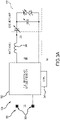
FIG. 3A is a schematic drawing illustrating a power circuit and a controller of the power supply ofFIG. 1 , in accordance with various embodiments; -
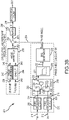
FIG. 3B is a schematic drawing illustrating various features of the controller ofFIG. 3A , in accordance with various embodiments; and -
FIG. 4 is a flowchart illustrating a method for controlling a power signal for zero voltage switching, in accordance with various embodiments. - The detailed description of exemplary embodiments herein makes reference to the accompanying drawings, which show exemplary embodiments by way of illustration. While these exemplary embodiments are described in sufficient detail to enable those skilled in the art to practice the exemplary embodiments of the disclosure, it should be understood that other embodiments may be realized and that logical changes and adaptations in design and construction may be made in accordance with this disclosure and the teachings herein. Thus, the detailed description herein is presented for purposes of illustration only and not limitation. The steps recited in any of the method or process descriptions may be executed in any order and are not necessarily limited to the order presented.
- Furthermore, any reference to singular includes plural embodiments, and any reference to more than one component or step may include a singular embodiment or step. Also, any reference to attached, fixed, connected or the like may include permanent, removable, temporary, partial, full and/or any other possible attachment option. Additionally, any reference to without contact (or similar phrases) may also include reduced contact or minimal contact. Surface shading lines may be used throughout the figures to denote different parts but not necessarily to denote the same or different materials.
- The present disclosure is directed to a new system and method for controlling an excimer lamp in aviation applications. The concept relates to a resonant frequency tracking and adjusting approach for zero voltage switching (ZVS) under a parameter change of the excimer lamp. The system calculates a phase angle using a phase locked loop (PLL). A bias generator determines a leading and lagging status. The output may be used as a feedback signal for the ZVS and resonant frequency tracking control. In the proposed system, the angle present value (based on deadtime value and inductor value) may be calculated and used as a reference for ZVS and resonant frequency tracking. Technically, the reference is the phase angle and the range may be within negative 3 decibels. Based on the reference and feedback, the phase angle error is calculated. A proportional-integral-derivative (PID) controller may adjust a pulse-width modulation (PWM) count value.
- Referring now to
FIGS. 1 and2 , a portion of anaircraft lavatory 100 may include one or moreUV excimer bulb 102. Theexcimer bulb 102 may emit UV light towards a portion of thelavatory 100, as shown by anarrow 106. Thelavatory 100 may further include apower supply 104 designed to provide a power signal to theexcimer bulb 102. In particular, thepower supply 104 may provide a relatively high voltage power signal (i.e., between 500 volts and 3 kilovolts (3 kV), between 1 kV and 3 kV, or between 1.5 kV and 2.5 kV). Thepower supply 104 may be designed to receive either direct current (DC) input power or alternating current (AC) input power, and may output an AC output power signal. Thepower supply 104 may be designed to provide a desirable power signal to theexcimer bulb 102 regardless of a status of theexcimer bulb 102. That is, over time, theexcimer bulb 102 may degrade and may have changing electrical properties as a result (e.g., a resistance or capacitance of theexcimer bulb 102 may change over time). Thepower supply 104 is designed to compensate for these changing electrical properties of theexcimer bulb 102. - Referring now to
FIGS. 3A and3B , thepower supply 104 may include apower circuit 300 and acontroller 301. Thepower circuit 300 may include abridge circuit 302 having one or more switch located therein, such as a transistor or any other switching circuit element. Thebridge circuit 302 may receive aninput voltage 306 and may generate a desirable waveform to control theexcimer lamp 102 by controlling the switches. In that regard, thepower circuit 300 may function as a resonant inverter. - The
controller 301 may control operation of the switches in thebridge circuit 302 based on various parameters, as described in more detail below. Thepower circuit 300 may further include aninductor 304 which is used to match a resonant frequency of theexcimer lamp 102. The output from theinductor 304 and thebridge circuit 302 may be used to power theexcimer lamp 102. In various embodiments, thepower circuit 300 may include any circuit with one or more switching element that can output power signals having a frequency usable to power theexcimer lamp 102. - The
controller 301 may include one or more logic devices such as one or more of a central processing unit (CPU), an accelerated processing unit (APU), a digital signal processor (DSP), a field programmable gate array (FPGA), an application specific integrated circuit (ASIC), or the like. In various embodiments, thecontroller 301 may further include any non-transitory memory known in the art. The memory may store instructions usable by the logic device to perform operations. The memory may also or instead store other data as instructed by thecontroller 301 such as calculated or desired phase angles. - The
controller 301 may include various modules that perform specific functions. The functions of the modules may be implemented in hardware (e.g., transistors, logic gates, etc.), firmware, software, or any combination thereof. - In more detail and as shown in
FIG. 3B , thecontroller 301 may include a phaseangle calculation module 202 that calculates a phase angle between an input voltage (i.e., the voltage across theexcimer lamp 102 inFIG. 3A ) and an input current (i.e., the current flowing through the inductor 304). Thecontroller 301 may further include a ZVS control and resonantfrequency tracking module 204 outputs a signal usable to control the switch(es) of thepower circuit 300. - The phase
angle calculation module 202 may include a voltage zerocrossing detection module 206 and a current zerocrossing detection module 208. The voltage zerocrossing detection module 206 may receive an inverter voltage signal 210 from a resonant inverter (e.g., the power circuit 300) and may detect a zero voltage condition corresponding to theinverter voltage signal 210 crossing zero volts. That is, theinverter voltage signal 210 may have a frequency and may alternate between positive and negative voltage values, and the voltage zerocrossing detection module 206 may detect when theinverter voltage signal 210 reaches zero volts when switching from positive to negative or from negative to positive. The current zerocrossing detection module 208 may receive an invertercurrent signal 212 from the resonant inverter and may detect a zero current condition corresponding to the invertercurrent signal 212 crossing zero volts. The voltage zerocrossing detection module 206 may output a zerovoltage signal 214 corresponding to the zero voltage condition detection. The current zerocrossing detection module 208 may output a zerocurrent signal 216 corresponding to the zero current condition. - A phase detect
module 218 may receive the zerovoltage signal 214 and the zerocurrent signal 216 corresponding to the zero voltage condition and the zero current condition. The phase detectmodule 218 may detect or determineactual phase data 226 corresponding to an actual phase angle between theinverter voltage signal 210 and the invertercurrent signal 212 based on the zerovoltage signal 214 and the zerocurrent signal 216. - The phase detect
module 218 may include a voltage phase locked loop (PLL)module 220 that receives the zerovoltage signal 214, and a current PLL module 222 that receives the zerocurrent signal 216. The phase detectmodule 218 may further include an and module 224 (which may function as an and gate) which receives the output of thevoltage PLL module 220 and the output of the current PLL module 222. The andmodule 224 may output an output signal having a value of logical true in response to the output of both of thevoltage PLL module 220 and the current PLL module 222 being a logical true. The output signal of the andmodule 224 may be fed into thevoltage PLL module 220 and the current PLL module 222 as additional inputs. The output signal of thevoltage PLL module 220 may be output as theactual phase data 226. - The
actual phase data 226 may have noise in addition to a signal representing the actual phase angle between theinverter voltage signal 210 and the invertercurrent signal 212. In that regard, theactual phase data 226 from the phase detectmodule 218 may be received by a low pass filter (LPF) 228. TheLPF 228 may filter theactual phase data 226 to remove noise having a relatively high frequency, and may output aconstant value 230 that corresponds to the actual phase angle. - A
bias generator 232 may receive theconstant value 230 from theLPF 228 and may output abiased phase angle 234 corresponding to the actual phase angle between theinverter voltage signal 210 and the invertercurrent signal 212. In particular, thebias generator 232 may add a bias voltage to theconstant value 230 such that thebiased phase angle 234 may operate in a preferred voltage region. - The ZVS control and resonant
frequency tracking module 204 may receive or determine adeadtime signal 238 and amatching inductance signal 240. Thedeadtime signal 238 may correspond to a period of time in which all switches of thecontrol circuit 300 are switched off and it allows for reduction or elimination of a short circuit effect within thecontrol circuit 300. The matchinginductance signal 240 corresponds to the inductance of theinductor 304. - The
deadtime signal 238 may be received by anangle conversion module 242 which converts thedeadtime signal 238 into anangle signal 246. The matchinginductance signal 240 may be received by anenergy calculation module 244 which may calculate anenergy signal 248 corresponding to an amount of energy at theinductor 304 based on the inverter current 212 and the matchinginductance signal 240. - An
angle reference module 250 may receive theangle signal 246 and theenergy signal 248 and may calculate or determine a desiredphase angle 252 between theinverter voltage signal 210 and the invertercurrent signal 212 based on theangle signal 246 and theenergy signal 248. The desiredphase angle 252 may be an angle at which the output of the resonant inverter may be used to properly power theexcimer lamp 102 and may be based on the changing electrical properties of theexcimer lamp 102. As referenced above, the electrical properties of theexcimer lamp 102 may vary as theexcimer lamp 102 is used. - A
comparator 254 may receive the desiredphase angle 252 and thebiased phase angle 234 and may determine adifference signal 255 corresponding to a difference in value between the desiredphase angle 252 and thebiased phase angle 234. APID controller 256 may receive thedifference signal 255 and may output acontroller signal 258 based on thedifference signal 255. Thecontroller signal 258 may be used to control the switches of the resonant inverter. ThePID controller 256 may continue to adjust thecontroller signal 258 to reduce the phase difference between the desiredphase angle 252 and the biased phase angle 234 (i.e., the actual phase angle). Amodulus 260 may be the specific signals used by thecontroller 301 to control the switches of the resonant inverter and may be based on thecontroller signal 258. - The
controller 301 may provide several benefits and advantages over conventional controllers that are used to control excimer lamps. In particular, thecontroller 301 achieves true zero voltage switching, which reduces power loss which may occur when ZVS fails to function properly (as is the case in conventional controllers when an excimer lamp degrades such that its electrical properties change). Additionally, thecontroller 301 achieves reduced electromagnetic interference (EMI) relative to conventional controllers by avoiding turn on transient values. Also, thecontroller 301 continues to provide a desired output voltage signal to the excimer lamp regardless of the changing electrical properties of the excimer lamp, which conventional controllers fail to provide. - Referring now to
FIG. 4 , amethod 400 for controlling a power signal for ZVS control of an excimer bulb is shown. Themethod 400 may be implemented using similar features as thecontroller 301 ofFIGS. 3A and3B . - The
method 400 may begin inblock 402 by detecting a zero voltage condition of an inverter voltage signal used to power an excimer bulb. Inblock 404, a zero current condition of an inverter current signal may be detected. - In
block 406, a phase detect circuit may detect actual phase data corresponding to a phase angle between the inverter voltage signal and the inverter current signal. Inblock 408, a LPF may be used to filter the actual phase data, which may result in a constant phase angle signal. Inblock 410, a bias generator may output a biased phase angle based on the constant phase angle from the LPF. - In
block 412, deadline data and matching inductor data may be compared to determine a desired phase angle between the inverter voltage signal and the inverter current signal. Inblock 414, a comparator may determine a phase difference between the desired phase angle and the biased (i.e., actual) phase angle. Inblock 416, a PID controller may adjust a property of at least one switch in of a resonant inverter to reduce the phase difference. The PID controller may adjust the property based on the phase difference that is output by the comparator. - Benefits and other advantages have been described herein with regard to specific embodiments. Furthermore, the connecting lines shown in the various figures contained herein are intended to represent exemplary functional relationships and/or physical couplings between the various elements. It should be noted that many alternative or additional functional relationships or physical connections may be present in a practical system. However, the benefits, advantages, and any elements that may cause any benefit or advantage to occur or become more pronounced are not to be construed as critical, required, or essential features or elements of the disclosure. The scope of the disclosure is accordingly to be limited by nothing other than the appended claims, in which reference to an element in the singular is not intended to mean "one and only one" unless explicitly so stated, but rather "one or more." Moreover, where a phrase similar to "at least one of A, B, or C" is used in the claims, it is intended that the phrase be interpreted to mean that A alone may be present in an embodiment, B alone may be present in an embodiment, C alone may be present in an embodiment, or that any combination of the elements A, B and C may be present in a single embodiment; for example, A and B, A and C, B and C, or A and B and C.
- Systems, methods and apparatus are provided herein. In the detailed description herein, references to "various embodiments", "one embodiment", "an embodiment", "an example embodiment", etc., indicate that the embodiment described may include a particular feature, structure, or characteristic, but every embodiment may not necessarily include the particular feature, structure, or characteristic. Moreover, such phrases are not necessarily referring to the same embodiment. Further, when a particular feature, structure, or characteristic is described in connection with an embodiment, it is submitted that it is within the knowledge of one skilled in the art to affect such feature, structure, or characteristic in connection with other embodiments whether or not explicitly described. After reading the description, it will be apparent to one skilled in the relevant art(s) how to implement the disclosure in alternative embodiments.
- Furthermore, no element, component, or method step in the present disclosure is intended to be dedicated to the public regardless of whether the element, component, or method step is explicitly recited in the claims. No claim element herein is to be construed under the provisions of 35 U.S.C. 12(f), unless the element is expressly recited using the phrase "means for." As used herein, the terms "comprises", "comprising", or any other variation thereof, are intended to cover a non-exclusive inclusion, such that a process, method, article, or apparatus that comprises a list of elements does not include only those elements but may include other elements not expressly listed or inherent to such process, method, article, or apparatus.
Claims (15)
- A system for controlling a power signal for zero voltage switching (ZVS), the system comprising:a voltage zero crossing detection module configured to detect a zero voltage condition in response to an inverter voltage from a resonant inverter crossing zero volts;a current zero crossing detection module configured to detect a zero current condition in response to an inverter current from the resonant inverter crossing zero amps;a phase detect module configured to detect actual phase data corresponding to an actual phase angle between the inverter voltage and the inverter current based on the zero voltage condition and the zero current condition;a comparator configured to determine a phase difference between a desired phase between the inverter voltage and the inverter current and the actual phase angle; anda controller configured to adjust a property of a resonant inverter to reduce the phase difference based on the phase difference.
- The system of claim 1, wherein the phase detect module includes:a voltage phase locked loop (PLL) module that receives voltage input corresponding to the zero voltage condition from the voltage zero crossing detection module; anda current PLL module that receives current input corresponding to the zero current condition from the current zero crossing detection module.
- The system of claim 2, further comprising an and module configured to receive an output of the voltage PLL module and an output of the current PLL module and to output an output signal in response to the output of the voltage PLL module and the output of the current PLL module both being true, wherein:the voltage PLL module further receives the output signal of the and module;the current PLL module further receives the output signal of the and module; andthe actual phase data determined by the phase detect module is taken as the output of the voltage PLL module.
- The system of any preceding claim, further comprising a low pass filter configured to receive the actual phase data from the phase detect module and to output a constant value corresponding to the actual phase angle.
- The system of claim 4, further comprising a bias generator configured to receive the constant value corresponding to the actual phase angle and to output a biased phase angle to be used by the comparator as the actual phase angle.
- The system of any preceding claim, further comprising an angle reference module configured to compare deadtime data and matching inductor data and to output the desired phase.
- The system of any preceding claim, wherein the controller is a proportional-integral-derivative (PID) controller configured to receive the phase difference and to output a controller signal to be used by the resonant inverter to reduce the phase difference.
- The system of claim 7, wherein the resonant inverter includes a plurality of switches, and the controller signal corresponds to control of the plurality of switches of the resonant inverter.
- The system of any preceding claim, wherein the power signal is configured for use by an excimer bulb, and/or
wherein the system is configured for use on an aircraft. - A system for controlling a power signal for zero voltage switching (ZVS) as recited in any preceding claim, the system comprising:
a resonant inverter having at least one switch and configured to output an inverter voltage and an inverter current,
wherein the controller is configured to adjust a property of the at least one switch of the resonant inverter to reduce the phase difference based on the phase difference. - A method for controlling a power signal for zero voltage switching (ZVS), the method comprising:detecting, by a voltage zero crossing detection module, a zero voltage condition in response to an inverter voltage from a resonant inverter crossing zero volts;detecting, by current zero crossing detection module, a zero current condition in response to an inverter current from the resonant inverter crossing zero amps;detecting, by a phase detect module, actual phase data corresponding to an actual phase angle between the inverter voltage and the inverter current based on the zero voltage condition and the zero current condition;determining, by a comparator, a phase difference between a desired phase between the inverter voltage and the inverter current and the actual phase angle; andadjusting, by a controller, a property of a resonant inverter to reduce the phase difference based on the phase difference.
- The method of claim 11, further comprising filtering, by a low pass filter, the actual phase data to output a constant value corresponding to the actual phase angle,
optionally further comprising outputting, by a bias generator, a based phase angle to be used by the comparator as the actual phase angle based on the constant value from the low pass filter. - The method of claim 11 or 12, further comprising comparing, by an angle reference module, deadline data and matching inductor data to determine the desired phase.
- The method of claim 11, 12 or 13, wherein the property of the resonant inverter corresponds to at least one switch of the resonant inverter.
- The method of any of claims 11 to 14, wherein the power signal is configured for use by an excimer bulb on an aircraft.
Applications Claiming Priority (1)
| Application Number | Priority Date | Filing Date | Title |
|---|---|---|---|
| US17/336,129 US11784553B2 (en) | 2021-06-01 | 2021-06-01 | Resonant frequency tracking for zero voltage switching |
Publications (1)
| Publication Number | Publication Date |
|---|---|
| EP4099556A1 true EP4099556A1 (en) | 2022-12-07 |
Family
ID=81850781
Family Applications (1)
| Application Number | Title | Priority Date | Filing Date |
|---|---|---|---|
| EP22175670.3A Pending EP4099556A1 (en) | 2021-06-01 | 2022-05-26 | Resonant frequency tracking for zero voltage switching |
Country Status (2)
| Country | Link |
|---|---|
| US (1) | US11784553B2 (en) |
| EP (1) | EP4099556A1 (en) |
Families Citing this family (1)
| Publication number | Priority date | Publication date | Assignee | Title |
|---|---|---|---|---|
| CN117937585B (en) * | 2023-12-18 | 2025-06-03 | 中国科学院空天信息创新研究院 | Inverter ZVS regulation and control method and device, electronic equipment and medium |
Family Cites Families (4)
| Publication number | Priority date | Publication date | Assignee | Title |
|---|---|---|---|---|
| US6274988B1 (en) | 2000-01-27 | 2001-08-14 | R-Can Environmental Inc. | Open loop current control ballast low pressure mercury germicidal UV lamps |
| US8228002B2 (en) * | 2008-09-05 | 2012-07-24 | Lutron Electronics Co., Inc. | Hybrid light source |
| DE102015117206A1 (en) | 2015-10-08 | 2017-04-13 | I.S.T. Innovative Sewer Technologies Gmbh | Curing device with a UV light-generating lamp |
| US10236174B1 (en) | 2017-12-28 | 2019-03-19 | Lucidity Lights, Inc. | Lumen maintenance in fluorescent lamps |
-
2021
- 2021-06-01 US US17/336,129 patent/US11784553B2/en active Active
-
2022
- 2022-05-26 EP EP22175670.3A patent/EP4099556A1/en active Pending
Non-Patent Citations (3)
| Title |
|---|
| BOONTAKLANG SUTTIPONG ET AL: "Automatic Resonance-Frequency Tuning and Tracking Technique for a 1MHz Ultrasonic-Piezoelectric-Transducer Driving Circuit in Medical Therapeutic Applications Using dsPIC Microcontroller and PLL Techniques", vol. 12, no. 6, 31 March 2019 (2019-03-31), pages 14 - 24, XP055968437, Retrieved from the Internet <URL:http://www.inass.org/2019/2019123102.pdf> DOI: 10.22266/ijies2019.1231.02 * |
| KARACA H: "Phase detector for tuning circuit of resonant inverters", ELECTRONICS LETTERS, THE INSTITUTION OF ENGINEERING AND TECHNOLOGY, GB, vol. 36, no. 11, 25 May 2000 (2000-05-25), pages 931 - 932, XP006015274, ISSN: 0013-5194, DOI: 10.1049/EL:20000716 * |
| LU KAIXING ET AL: "A Novel Efficiency-oriented Frequency Tracking Method for WPT Systems", 2019 22ND INTERNATIONAL CONFERENCE ON ELECTRICAL MACHINES AND SYSTEMS (ICEMS), IEEE, 11 August 2019 (2019-08-11), pages 1 - 5, XP033643300, DOI: 10.1109/ICEMS.2019.8921703 * |
Also Published As
| Publication number | Publication date |
|---|---|
| US20220385167A1 (en) | 2022-12-01 |
| US11784553B2 (en) | 2023-10-10 |
Similar Documents
| Publication | Publication Date | Title |
|---|---|---|
| US8817509B2 (en) | High frequency power supply device | |
| US10652965B2 (en) | Apparatus, dimmable light emitting diode drive circuit and control method | |
| US9949328B1 (en) | Constant voltage output AC phase dimmable LED driver | |
| JP3197169B2 (en) | Lighting circuit of discharge lamp | |
| TWI392213B (en) | Power supply | |
| US8482940B2 (en) | Illumination lighting device, discharge lamp lighting device, and vehicle headlamp lighting device using same | |
| JP5637688B2 (en) | Inverter device and X-ray high voltage device using the inverter device | |
| US20130176004A1 (en) | Switching mode power supply | |
| CN102934524A (en) | Open circuit voltage clamp for electronic hid ballast | |
| US5777864A (en) | Resonant converter control system having resonant current phase detection | |
| US9595886B2 (en) | Vehicle auxiliary power supply device and overcurrent protection method thereof | |
| US9979309B1 (en) | Synchronous rectification controller | |
| EP2740201B1 (en) | A controller for a voltage converter | |
| US11723125B2 (en) | Method and system for a flicker-free light dimmer in an electricity distribution network | |
| US11784553B2 (en) | Resonant frequency tracking for zero voltage switching | |
| CN105050232A (en) | Sampling for dimmer edge detection in power converter | |
| KR20100045431A (en) | Multi-control led driving circuit | |
| JP5708988B2 (en) | High frequency power supply | |
| KR101104370B1 (en) | Pulsed pulse power supply device having arc control means and arc control method in the device | |
| EP3935919B1 (en) | Improved led short circuit and open load detection with a single controller pin | |
| JP2008010425A (en) | Voltage feedback circuit for lcd backlight inverter | |
| US9614430B2 (en) | Inverting apparatus and AC power system using the same | |
| JP4061078B2 (en) | Power supply | |
| US11843323B2 (en) | Transformer-less AC-DC input compatible boost resonant inverter | |
| JP2010041836A (en) | Switching power unit |
Legal Events
| Date | Code | Title | Description |
|---|---|---|---|
| PUAI | Public reference made under article 153(3) epc to a published international application that has entered the european phase |
Free format text: ORIGINAL CODE: 0009012 |
|
| STAA | Information on the status of an ep patent application or granted ep patent |
Free format text: STATUS: THE APPLICATION HAS BEEN PUBLISHED |
|
| AK | Designated contracting states |
Kind code of ref document: A1 Designated state(s): AL AT BE BG CH CY CZ DE DK EE ES FI FR GB GR HR HU IE IS IT LI LT LU LV MC MK MT NL NO PL PT RO RS SE SI SK SM TR |
|
| STAA | Information on the status of an ep patent application or granted ep patent |
Free format text: STATUS: REQUEST FOR EXAMINATION WAS MADE |
|
| 17P | Request for examination filed |
Effective date: 20230607 |
|
| RBV | Designated contracting states (corrected) |
Designated state(s): AL AT BE BG CH CY CZ DE DK EE ES FI FR GB GR HR HU IE IS IT LI LT LU LV MC MK MT NL NO PL PT RO RS SE SI SK SM TR |
|
| P01 | Opt-out of the competence of the unified patent court (upc) registered |
Effective date: 20230922 |
|
| STAA | Information on the status of an ep patent application or granted ep patent |
Free format text: STATUS: EXAMINATION IS IN PROGRESS |
|
| 17Q | First examination report despatched |
Effective date: 20250707 |