EP4099489A1 - Battery pack comprising heat dissipation structure of protective circuit module using heat dissipation tape - Google Patents
Battery pack comprising heat dissipation structure of protective circuit module using heat dissipation tape Download PDFInfo
- Publication number
- EP4099489A1 EP4099489A1 EP21886759.6A EP21886759A EP4099489A1 EP 4099489 A1 EP4099489 A1 EP 4099489A1 EP 21886759 A EP21886759 A EP 21886759A EP 4099489 A1 EP4099489 A1 EP 4099489A1
- Authority
- EP
- European Patent Office
- Prior art keywords
- circuit module
- contact part
- protection circuit
- tape
- contact
- Prior art date
- Legal status (The legal status is an assumption and is not a legal conclusion. Google has not performed a legal analysis and makes no representation as to the accuracy of the status listed.)
- Granted
Links
Images


Classifications
-
- H—ELECTRICITY
- H01—ELECTRIC ELEMENTS
- H01M—PROCESSES OR MEANS, e.g. BATTERIES, FOR THE DIRECT CONVERSION OF CHEMICAL ENERGY INTO ELECTRICAL ENERGY
- H01M50/00—Constructional details or processes of manufacture of the non-active parts of electrochemical cells other than fuel cells, e.g. hybrid cells
- H01M50/20—Mountings; Secondary casings or frames; Racks, modules or packs; Suspension devices; Shock absorbers; Transport or carrying devices; Holders
- H01M50/204—Racks, modules or packs for multiple batteries or multiple cells
- H01M50/207—Racks, modules or packs for multiple batteries or multiple cells characterised by their shape
- H01M50/209—Racks, modules or packs for multiple batteries or multiple cells characterised by their shape adapted for prismatic or rectangular cells
-
- H—ELECTRICITY
- H01—ELECTRIC ELEMENTS
- H01M—PROCESSES OR MEANS, e.g. BATTERIES, FOR THE DIRECT CONVERSION OF CHEMICAL ENERGY INTO ELECTRICAL ENERGY
- H01M10/00—Secondary cells; Manufacture thereof
- H01M10/42—Methods or arrangements for servicing or maintenance of secondary cells or secondary half-cells
-
- H—ELECTRICITY
- H01—ELECTRIC ELEMENTS
- H01M—PROCESSES OR MEANS, e.g. BATTERIES, FOR THE DIRECT CONVERSION OF CHEMICAL ENERGY INTO ELECTRICAL ENERGY
- H01M10/00—Secondary cells; Manufacture thereof
- H01M10/42—Methods or arrangements for servicing or maintenance of secondary cells or secondary half-cells
- H01M10/425—Structural combination with electronic components, e.g. electronic circuits integrated to the outside of the casing
-
- H—ELECTRICITY
- H01—ELECTRIC ELEMENTS
- H01M—PROCESSES OR MEANS, e.g. BATTERIES, FOR THE DIRECT CONVERSION OF CHEMICAL ENERGY INTO ELECTRICAL ENERGY
- H01M10/00—Secondary cells; Manufacture thereof
- H01M10/60—Heating or cooling; Temperature control
- H01M10/61—Types of temperature control
- H01M10/613—Cooling or keeping cold
-
- H—ELECTRICITY
- H01—ELECTRIC ELEMENTS
- H01M—PROCESSES OR MEANS, e.g. BATTERIES, FOR THE DIRECT CONVERSION OF CHEMICAL ENERGY INTO ELECTRICAL ENERGY
- H01M10/00—Secondary cells; Manufacture thereof
- H01M10/60—Heating or cooling; Temperature control
- H01M10/65—Means for temperature control structurally associated with the cells
- H01M10/653—Means for temperature control structurally associated with the cells characterised by electrically insulating or thermally conductive materials
-
- H—ELECTRICITY
- H01—ELECTRIC ELEMENTS
- H01M—PROCESSES OR MEANS, e.g. BATTERIES, FOR THE DIRECT CONVERSION OF CHEMICAL ENERGY INTO ELECTRICAL ENERGY
- H01M10/00—Secondary cells; Manufacture thereof
- H01M10/60—Heating or cooling; Temperature control
- H01M10/65—Means for temperature control structurally associated with the cells
- H01M10/655—Solid structures for heat exchange or heat conduction
-
- H—ELECTRICITY
- H01—ELECTRIC ELEMENTS
- H01M—PROCESSES OR MEANS, e.g. BATTERIES, FOR THE DIRECT CONVERSION OF CHEMICAL ENERGY INTO ELECTRICAL ENERGY
- H01M10/00—Secondary cells; Manufacture thereof
- H01M10/60—Heating or cooling; Temperature control
- H01M10/66—Heat-exchange relationships between the cells and other systems, e.g. central heating systems or fuel cells
- H01M10/667—Heat-exchange relationships between the cells and other systems, e.g. central heating systems or fuel cells the system being an electronic component, e.g. a CPU, an inverter or a capacitor
-
- H—ELECTRICITY
- H01—ELECTRIC ELEMENTS
- H01M—PROCESSES OR MEANS, e.g. BATTERIES, FOR THE DIRECT CONVERSION OF CHEMICAL ENERGY INTO ELECTRICAL ENERGY
- H01M50/00—Constructional details or processes of manufacture of the non-active parts of electrochemical cells other than fuel cells, e.g. hybrid cells
- H01M50/20—Mountings; Secondary casings or frames; Racks, modules or packs; Suspension devices; Shock absorbers; Transport or carrying devices; Holders
-
- H—ELECTRICITY
- H01—ELECTRIC ELEMENTS
- H01M—PROCESSES OR MEANS, e.g. BATTERIES, FOR THE DIRECT CONVERSION OF CHEMICAL ENERGY INTO ELECTRICAL ENERGY
- H01M50/00—Constructional details or processes of manufacture of the non-active parts of electrochemical cells other than fuel cells, e.g. hybrid cells
- H01M50/20—Mountings; Secondary casings or frames; Racks, modules or packs; Suspension devices; Shock absorbers; Transport or carrying devices; Holders
- H01M50/204—Racks, modules or packs for multiple batteries or multiple cells
- H01M50/207—Racks, modules or packs for multiple batteries or multiple cells characterised by their shape
- H01M50/211—Racks, modules or packs for multiple batteries or multiple cells characterised by their shape adapted for pouch cells
-
- H—ELECTRICITY
- H01—ELECTRIC ELEMENTS
- H01M—PROCESSES OR MEANS, e.g. BATTERIES, FOR THE DIRECT CONVERSION OF CHEMICAL ENERGY INTO ELECTRICAL ENERGY
- H01M50/00—Constructional details or processes of manufacture of the non-active parts of electrochemical cells other than fuel cells, e.g. hybrid cells
- H01M50/50—Current conducting connections for cells or batteries
- H01M50/572—Means for preventing undesired use or discharge
-
- H—ELECTRICITY
- H01—ELECTRIC ELEMENTS
- H01M—PROCESSES OR MEANS, e.g. BATTERIES, FOR THE DIRECT CONVERSION OF CHEMICAL ENERGY INTO ELECTRICAL ENERGY
- H01M2200/00—Safety devices for primary or secondary batteries
-
- H—ELECTRICITY
- H01—ELECTRIC ELEMENTS
- H01M—PROCESSES OR MEANS, e.g. BATTERIES, FOR THE DIRECT CONVERSION OF CHEMICAL ENERGY INTO ELECTRICAL ENERGY
- H01M50/00—Constructional details or processes of manufacture of the non-active parts of electrochemical cells other than fuel cells, e.g. hybrid cells
- H01M50/20—Mountings; Secondary casings or frames; Racks, modules or packs; Suspension devices; Shock absorbers; Transport or carrying devices; Holders
- H01M50/289—Mountings; Secondary casings or frames; Racks, modules or packs; Suspension devices; Shock absorbers; Transport or carrying devices; Holders characterised by spacing elements or positioning means within frames, racks or packs
- H01M50/291—Mountings; Secondary casings or frames; Racks, modules or packs; Suspension devices; Shock absorbers; Transport or carrying devices; Holders characterised by spacing elements or positioning means within frames, racks or packs characterised by their shape
-
- H—ELECTRICITY
- H01—ELECTRIC ELEMENTS
- H01M—PROCESSES OR MEANS, e.g. BATTERIES, FOR THE DIRECT CONVERSION OF CHEMICAL ENERGY INTO ELECTRICAL ENERGY
- H01M50/00—Constructional details or processes of manufacture of the non-active parts of electrochemical cells other than fuel cells, e.g. hybrid cells
- H01M50/20—Mountings; Secondary casings or frames; Racks, modules or packs; Suspension devices; Shock absorbers; Transport or carrying devices; Holders
- H01M50/289—Mountings; Secondary casings or frames; Racks, modules or packs; Suspension devices; Shock absorbers; Transport or carrying devices; Holders characterised by spacing elements or positioning means within frames, racks or packs
- H01M50/293—Mountings; Secondary casings or frames; Racks, modules or packs; Suspension devices; Shock absorbers; Transport or carrying devices; Holders characterised by spacing elements or positioning means within frames, racks or packs characterised by the material
-
- Y—GENERAL TAGGING OF NEW TECHNOLOGICAL DEVELOPMENTS; GENERAL TAGGING OF CROSS-SECTIONAL TECHNOLOGIES SPANNING OVER SEVERAL SECTIONS OF THE IPC; TECHNICAL SUBJECTS COVERED BY FORMER USPC CROSS-REFERENCE ART COLLECTIONS [XRACs] AND DIGESTS
- Y02—TECHNOLOGIES OR APPLICATIONS FOR MITIGATION OR ADAPTATION AGAINST CLIMATE CHANGE
- Y02E—REDUCTION OF GREENHOUSE GAS [GHG] EMISSIONS, RELATED TO ENERGY GENERATION, TRANSMISSION OR DISTRIBUTION
- Y02E60/00—Enabling technologies; Technologies with a potential or indirect contribution to GHG emissions mitigation
- Y02E60/10—Energy storage using batteries
Definitions
- the disclosure relates to a battery pack, and more specifically, to a pouch-type battery pack including a heat radiation structure using a heat radiation tape.
- Secondary batteries may be classified into a cylindrical type, a polygonal type, a pouch type, and the like according to the shape of a case.
- the shape of a pouch-type secondary battery is easily transformable according to a product, and the pouch-type secondary battery is advantageous in terms of cheap production costs and small weight.
- the pouch-type secondary battery is properly applicable to various IT devices such as mobile devices.
- a pouch-type battery pack has a structure in which a protection circuit module (PCM) is installed on a cell terrace part of a plate-shaped battery cell.
- PCM protection circuit module
- the outer surface of the protection circuit module (PCM) is covered and wrapped by a PORON tape simply in a " " shape, and the upper portion thereof is covered and wrapped by an upper tape.
- the Poron tape refers to a tape for buffering an impact transferred to a protection circuit module (PCM) when an impact is applied from the outside to a battery pack.
- a protection circuit module In a protection circuit module (PCM), an FET mounted on a circuit substrate is mainly the largest heating factor. As described above, in the case of a structure in which a protection circuit module is wrapped by a PORON tape and an upper tape, a state in which heat generated in the protection circuit module (PCM) by the FET is not emitted is maintained, and the temperature further increases due to heat that persists over time.
- a protection circuit module applied to a battery pack having a great charging current has a structure in which a plurality of FETs are disposed, and in this case, the above-described limitation related to heating of a protection circuit module (PCM) becomes worse.
- the disclosure provides a pouch-type battery pack including a protection circuit module (PCM) heating improvement structure using a heat radiation tape.
- PCM protection circuit module
- a battery pack in accordance with the disclosure includes: a plate-shaped battery cell which includes a cell terrace part extending upward on one side surface thereof, and has a pair of electrode leads protruding outward through the cell terrace part; a protection circuit module (PCM) which includes two FETs disposed on each of the upper and lower surfaces thereof, and is installed on the cell terrace part; a heat radiation tape which is attached while wrapping the protection circuit module (PCM) in a " " shape to form a contact region at each of the side surface of the battery cell, a region between the protection circuit module (PCM) and the cell terrace part, and the upper portion of the protection circuit module (PCM); and an upper tape which covers the upper portion of the protection circuit module (PCM) wrapped by the heat radiation tape.
- PCM protection circuit module
- the battery pack may further include: a lower tape which covers the lower surface of the battery cell; a side surface tape which covers each of both side surfaces of the battery cell; and a front surface tape which is attached to the front surface of the battery cell.
- the heat radiation tape may include: a first contact part which is in contact with the upper surface of the protection circuit module (PCM); a second contact part which is in contact with a region between the side surface of the protection circuit module (PCM) and the upper end surface of the battery cell in a shape of being bent and extending from the first contact part; a third contact part which is in contact with a region between the lower surface of the protection circuit module (PCM) and the upper surface of the cell terrace part in a shape of being bent and extending from the second contact part; a fourth contact part which is in contact with the side portion of the cell terrace part in a shape of being bent and extending from the third contact part; and a fifth contact part which is in contact with the lower surface of the cell terrace part in a shape of being bent and extending from the fourth contact part.
- PCM protection circuit module
- the heat radiation tape may form an FET-generating heat transfer path through which heat generated from the FET of the protection circuit module (PCM) moves in the direction from the first contact part to the fifth contact part.
- PCM protection circuit module
- heat moving through the FET-generating heat transfer path may be emitted after being dispersed through each of the first contact part, the fourth contact part, and the fifth contact part.
- the heat radiation tape may be made of a material having a high heat conductivity.
- the heat radiation tape may be made of a graphite tape or a synthetic tape including aluminum (Al).
- the heat radiation tape may be attached in a structure of forming a first contact part which is in contact with the upper surface of the protection circuit module (PCM), a second contact part which is in contact with a region between the side surface of the protection circuit module (PCM) and the upper end surface of the battery cell in a shape of being bent and extending from the first contact part, a third contact part which is in contact with a region between the lower surface of the protection circuit module (PCM) and the upper surface of the cell terrace part in a shape of being bent and extending from the second contact part, a fourth contact part which is in contact with the side portion of the cell terrace part in a shape of being bent and extending from the third contact part, and a fifth contact part which is in contact with the lower surface of the cell terrace part in a shape of being bent and extending from the fourth contact part.
- PCM protection circuit module
- the heat radiation tape may form an FET-generating heat transfer path through which heat generated from the FET of the protection circuit module moves in the direction from the first contact part to the fifth contact part.
- heat moving through the FET-generating heat transfer path may be emitted after being dispersed through each of the first contact part, the fourth contact part, and the fifth contact part.
- the heat radiation tape may be made of a material having a high heat conductivity.
- the heat radiation tape may be made of a graphite tape or a synthetic tape including aluminum (Al).
- a battery pack of the disclosure is maintained in a shape overall similar to that of a conventional battery pack.
- a PORON tape applied to a conventional battery pack is changed into a tape having a high heat conductivity, and the battery pack of the disclosure includes an FET heat radiation structure of dispersively radiating FET-generating heat through a plurality of regions by using the tape.
- FIG. 1 is an exploded view showing a disassembled state of a battery pack in accordance with the disclosure
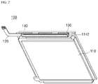
- FIG. 2 is a view illustrating a coupled state of components of FIG. 1 .
- a battery pack 100 of the disclosure largely includes a plate-shaped battery cell 110, a protection circuit module (PCM) 120, a heat radiation tape 130, and first to fourth tapes 140-170.
- PCM protection circuit module
- a plates-shaped battery cell has a structure in which an electrode assembly including a positive electrode plate, a negative electrode plate, and a separator is sealed in a pouch, and the pouch may be formed in a multilayer sheet structure wrapping the electrode assembly.
- the pouch includes a cell terrace part 1142 extending from one side thereof.
- the cell terrace part 1142 forms a predetermined region, and a pair of electrode leads of a battery cell protrude outward through the region.
- a protection circuit module 120 to be described hereinafter may be stably placed on the cell terrace part 1142.
- PCM Protection circuit module
- a protection circuit module provides functions such as battery pack overcharge protection, overdischarge protection, overcurrent protection, and short circuit protection.
- Such a protection circuit module (PCM) is installed on the cell terrace part 1142 as described above.
- the protection circuit module has a general structure including: a printed circuit board (PCB) 122 in which printed circuit patterns and various electronic components that may provide an overcharge protection function, an overdischarge protection function, an overcurrent protection function, and a short circuit protection function to the battery cell 110 are gathered; and an external input/output terminal 124 which is electrically connected to the PCB 122 and has a connector 1242 formed at the end thereof to be connectable to an external device.
- PCB printed circuit board
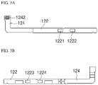
- FIG. 3A and FIG. 3B are views illustrating the upper and lower surfaces of a protection circuit module (PCM), respectively.
- the protection circuit module of the disclosure is a protection circuit module applied to a battery pack having a charging current of 2.0 C or greater.
- Such a protection circuit module has a structure in which two of FETs 1221, 1222, 1223, and 1224 are installed on each of the upper surface or the lower surface thereof as shown in FIG. 3A and FIG. 3B .
- a heat radiation tape is attached in a shape of wrapping the protection circuit module (PCM) 120 to form a predetermined heat radiation structure, and thus plays roles of stably fixing the protection circuit module 120 onto the cell terrace part 1142 and radiating heat generated from the protection circuit module 120.
- PCM protection circuit module
- the predetermined heat radiation structure may be a structure of forming a contact region at each of the side surface of the battery cell 110, a region between the protection circuit module 120 and the cell terrace part, and the upper portion of the protection circuit module (PCM) 120.
- PCM protection circuit module
- the heat radiation tape may be attached in a shape of wrapping the protection circuit module 120 to form a first contact part 130a which is in contact with the upper surface of the protection circuit module 120, a second contact part 130b which is in contact with a region between the side surface of the protection circuit module 120 and the upper end surface of the battery cell 110 in a shape of being bent and extending from the first contact part 130a, a third contact part 130c which is in contact with a region between the lower surface of the protection circuit module 120 and the upper surface of the cell terrace part 1142 in a shape of being bent and extending from the second contact part 130b, a fourth contact part 130d which is in contact with the side portion of the cell terrace part 1142 in a shape of being bent and extending from the third contact part 130c, and a fifth contact part 130e which is in contact with the lower surface of the cell terrace part 1142 in a shape of being bent and extending from the fourth contact part 130d. That is, the heat radiation tape wraps the protection circuit module 120 in a " " shape.
- the heat radiation tape attached in such a shape may be made of a material having a high heat conductivity.
- the heat radiation tape may be a graphite tape or a synthetic tape including aluminum (Al).
- the heat radiation tape 130 may form a generated heat transfer path in a direction from the first contact part 130a to the second contact part 130b, the third contact part 130c, the fourth contact part 130d, and then the fifth contact part 130e as shown by arrows indicated in FIG. 4 . Accordingly, while heat generated from FETs 1221, 1222, 1223, and 1224 moves in the direction of a heat conducting path as described above, the heat may be dispersively radiated through the first contact part 130a, the fourth contact part 130d, and the fifth contact part 130e which are exposed to the outside.
- the heat radiation tape of the disclosure may bring a result of effectively improving heating of a battery pack 100 by radiating heat generated from the protection circuit module 120.
- an upper tape is formed to wrap the upper portion of the protection circuit module (PCM) 120 wrapped by the heat radiation tape 130, and thus plays roles of stably fixing the protection circuit module (PCM) 120 to the cell terrace part 1142 and protecting the protection circuit module from the outside.
- a lower tape is attached in a shape of wrapping the lower surface of the battery cell 110 to cover the lower surface of the battery cell 110.
- a side surface tape is attached in a shape of wrapping each of both side surfaces of the battery cell 110 to cover the both side surfaces of the battery cell 110.
- a front surface tape is attached to the front surface of the battery cell 110.
- a pad print (not shown) indicating pack information including a serial number or the like of a battery pack 100 may be attached to the upper surface of a fourth tape.
- the first to fourth tapes 140-170 described above are general components applied to a pouch-type battery pack 100.
- a method for manufacturing a pouch-type battery pack in accordance with the disclosure may include the steps as described hereinafter.
- a heat radiation tape 130 is attached in a shape of wrapping a protection circuit module 120 to form a predetermined heat radiation structure, and thus the protection circuit module 120 may be installed on a cell terrace part 1142 extending from one side of a plate-shaped battery cell 110.
- the predetermined heat radiation structure may be a structure of forming a contact region at each of the side surface of the battery cell 110, a region between the protection circuit module 120 and the cell terrace part 1142, and the upper portion of the protection circuit module 120.
- the heat radiation tape may be attached in a shape of wrapping the protection circuit module 120 to form a first contact part 130a which is in contact with the upper surface of the protection circuit module 120, a second contact part 130b which is in contact with a region between the side surface of the protection circuit module 120 and the upper end surface of the battery cell 110 in a shape of being bent and extending from the first contact part 130a, a third contact part 130c which is in contact with a region between the lower surface of the protection circuit module 120 and the upper surface of the cell terrace part 1142 in a shape of being bent and extending from the second contact part 130b, a fourth contact part 130d which is in contact with the side portion of the cell terrace part 1142 in a shape of being bent and extending from the third contact part 130c, and a fifth contact part 130e which is in contact with the lower surface of the cell terrace part 1142 in a shape of being bent and extending from the fourth contact part 130d.
- the heat radiation tape 130 is made of a graphite tape or a synthetic tape including aluminum (Al).
- a generated heat transfer path is formed in a direction from the first contact part 130a to the second contact part 130b, the third contact part 130c, the fourth contact part 130d, and then the fifth contact part 130e.
- Heat moving through the path may be dispersively radiated through the first contact part 130a, the fourth contact part 130d, and the fifth contact part 130e which are in contact with the outside. Accordingly, heat generated from the protection circuit module 120 may be effectively emitted.
- the protection circuit module 120 has a structure which is applied to a battery pack having a charging current of 2.0 C or greater and in which two of FETs 1221, 1222, 1223, and 1224 are installed on each of the upper surface or the lower surface thereof as shown in FIG. 3A and FIG. 3B .
- a heating level by an FET which is a main heating factor is high.
- a heating level may be effectively reduced through the heat radiation structure of the heat radiation tape 130 as described above.
- a side surface covering step the side surfaces of the battery cell 110 are covered by attaching a side surface tape 160 to each of both side surfaces of the battery cell 110.
- an upper tape 140 is attached in a shape of wrapping the upper portion of the battery cell 110 where the protection circuit module 120 is installed, and a lower tape 150 is attached in a shape of wrapping the lower portion of the battery cell 110, such that the upper and lower portions of the battery cell 110 are respectively covered.
- a front surface tape is attached to the front surface of the battery cell 110.
- a pad print (not shown) indicating pack information including a serial number or the like of a battery pack 100 may be attached to the upper surface of the front surface tape after the front surface tape is attached.
Landscapes
- Chemical & Material Sciences (AREA)
- Chemical Kinetics & Catalysis (AREA)
- Electrochemistry (AREA)
- General Chemical & Material Sciences (AREA)
- Engineering & Computer Science (AREA)
- Manufacturing & Machinery (AREA)
- Microelectronics & Electronic Packaging (AREA)
- Battery Mounting, Suspending (AREA)
- Secondary Cells (AREA)
Abstract
Description
- The disclosure relates to a battery pack, and more specifically, to a pouch-type battery pack including a heat radiation structure using a heat radiation tape.
- In the modern society, as technologies for various IT devices including mobile devices and the like are developed and demands therefor increase, the development of technologies for and demands for secondary batteries serving as an energy source for IT devices are increasing.
- Secondary batteries may be classified into a cylindrical type, a polygonal type, a pouch type, and the like according to the shape of a case. The shape of a pouch-type secondary battery is easily transformable according to a product, and the pouch-type secondary battery is advantageous in terms of cheap production costs and small weight. Thus, in the recent trends of size reduction/weight reduction, the pouch-type secondary battery is properly applicable to various IT devices such as mobile devices.
- Generally, a pouch-type battery pack has a structure in which a protection circuit module (PCM) is installed on a cell terrace part of a plate-shaped battery cell. At this time, the outer surface of the protection circuit module (PCM) is covered and wrapped by a PORON tape simply in a "" shape, and the upper portion thereof is covered and wrapped by an upper tape. Here, the Poron tape refers to a tape for buffering an impact transferred to a protection circuit module (PCM) when an impact is applied from the outside to a battery pack.

- In a protection circuit module (PCM), an FET mounted on a circuit substrate is mainly the largest heating factor. As described above, in the case of a structure in which a protection circuit module is wrapped by a PORON tape and an upper tape, a state in which heat generated in the protection circuit module (PCM) by the FET is not emitted is maintained, and the temperature further increases due to heat that persists over time. In particular, a protection circuit module applied to a battery pack having a great charging current has a structure in which a plurality of FETs are disposed, and in this case, the above-described limitation related to heating of a protection circuit module (PCM) becomes worse.
- The continuous heating of a protection circuit module (PCM) causes limitations such as damage to components, degradation, and the risk of battery pack explosion.
(patent document 1)KR10-2018-0103625A - To overcome the limitations described above, the disclosure provides a pouch-type battery pack including a protection circuit module (PCM) heating improvement structure using a heat radiation tape.
- A battery pack in accordance with the disclosure includes: a plate-shaped battery cell which includes a cell terrace part extending upward on one side surface thereof, and has a pair of electrode leads protruding outward through the cell terrace part; a protection circuit module (PCM) which includes two FETs disposed on each of the upper and lower surfaces thereof, and is installed on the cell terrace part; a heat radiation tape which is attached while wrapping the protection circuit module (PCM) in a "" shape to form a contact region at each of the side surface of the battery cell, a region between the protection circuit module (PCM) and the cell terrace part, and the upper portion of the protection circuit module (PCM); and an upper tape which covers the upper portion of the protection circuit module (PCM) wrapped by the heat radiation tape.

- The battery pack may further include: a lower tape which covers the lower surface of the battery cell; a side surface tape which covers each of both side surfaces of the battery cell; and a front surface tape which is attached to the front surface of the battery cell.
- The heat radiation tape may include: a first contact part which is in contact with the upper surface of the protection circuit module (PCM); a second contact part which is in contact with a region between the side surface of the protection circuit module (PCM) and the upper end surface of the battery cell in a shape of being bent and extending from the first contact part; a third contact part which is in contact with a region between the lower surface of the protection circuit module (PCM) and the upper surface of the cell terrace part in a shape of being bent and extending from the second contact part; a fourth contact part which is in contact with the side portion of the cell terrace part in a shape of being bent and extending from the third contact part; and a fifth contact part which is in contact with the lower surface of the cell terrace part in a shape of being bent and extending from the fourth contact part.
- Accordingly, the heat radiation tape may form an FET-generating heat transfer path through which heat generated from the FET of the protection circuit module (PCM) moves in the direction from the first contact part to the fifth contact part.
- At this time, heat moving through the FET-generating heat transfer path may be emitted after being dispersed through each of the first contact part, the fourth contact part, and the fifth contact part.
- The heat radiation tape may be made of a material having a high heat conductivity.
- Specifically, the heat radiation tape may be made of a graphite tape or a synthetic tape including aluminum (Al).
- A method for manufacturing a battery pack including a structure which radiates heat generated from an FET installed in a protection circuit module (PCM), in accordance with the disclosure, includes: a protection circuit module installation step of installing the protection circuit module (PCM) on a cell terrace part by using a heat radiation tape having a "" shape to form a contact region at each of the side surface of a battery cell, a region between the protection circuit module (PCM) and the cell terrace part extending upward on one side surface of the battery cell, and the upper portion of the protection circuit module (PCM); a side surface covering step of covering the side surfaces of the battery cell by attaching a side surface tape to each of both side surfaces of the battery cell; an upper and lower portion covering step of attaching upper and lower tapes to the upper and lower portions of the battery cell, respectively, to cover the upper and lower portions of the battery cell; and a front surface covering step of attaching a front surface tape to the front surface of the battery cell to cover the front surface of the battery cell.

- Specifically, in the protection circuit module installation step, the heat radiation tape may be attached in a structure of forming a first contact part which is in contact with the upper surface of the protection circuit module (PCM), a second contact part which is in contact with a region between the side surface of the protection circuit module (PCM) and the upper end surface of the battery cell in a shape of being bent and extending from the first contact part, a third contact part which is in contact with a region between the lower surface of the protection circuit module (PCM) and the upper surface of the cell terrace part in a shape of being bent and extending from the second contact part, a fourth contact part which is in contact with the side portion of the cell terrace part in a shape of being bent and extending from the third contact part, and a fifth contact part which is in contact with the lower surface of the cell terrace part in a shape of being bent and extending from the fourth contact part.
- At this time, the heat radiation tape may form an FET-generating heat transfer path through which heat generated from the FET of the protection circuit module moves in the direction from the first contact part to the fifth contact part.
- Here, heat moving through the FET-generating heat transfer path may be emitted after being dispersed through each of the first contact part, the fourth contact part, and the fifth contact part.
- The heat radiation tape may be made of a material having a high heat conductivity.
- Specifically, the heat radiation tape may be made of a graphite tape or a synthetic tape including aluminum (Al).
- A battery pack of the disclosure is maintained in a shape overall similar to that of a conventional battery pack. A PORON tape applied to a conventional battery pack is changed into a tape having a high heat conductivity, and the battery pack of the disclosure includes an FET heat radiation structure of dispersively radiating FET-generating heat through a plurality of regions by using the tape.
- Accordingly, while pack processibility is maintained at the same level as before, heat generated from an FET of a PCM is effectively dispersively radiated, so that an effect of preventing damage to components, degradation, and the risk of battery pack explosion, which are caused by continuous heating of the PCM, is secured.
- Exemplary embodiments can be understood in more detail from the following description taken in conjunction with the accompanying drawings, in which:
-
FIG. 1 is a view illustrating a disassembled state of a battery pack in accordance with the disclosure; -
FIG. 2 is a view illustrating a battery pack of the disclosure; -
FIG. 3A is a view illustrating a structure of a protection circuit module (PCM) applied to a battery pack of the disclosure, andFIG. 3B is a view illustrating a structure of a protection circuit module (PCM) applied to a battery pack of the disclosure; and -
FIG. 4 is a cross-sectional view illustrating a part of a battery pack of the disclosure, the part being viewed from the side direction. - Hereinafter, embodiments will be described in detail with reference to the accompanying drawings to be easily carried out by those skilled in the art to which the disclosure belongs. The disclosure may, however, be embodied in various different forms and is not limited to the embodiments set forth herein. In addition, in order to clearly explain the disclosure in the drawings, parts irrelevant to the description are omitted, and similar reference numerals are assigned to similar parts throughout the specification.
- Hereinafter, the disclosure will be described in detail with reference to the drawings.
-
FIG. 1 is an exploded view showing a disassembled state of a battery pack in accordance with the disclosure, andFIG. 2 is a view illustrating a coupled state of components ofFIG. 1 . Referring toFIG. 1 andFIG. 2 , abattery pack 100 of the disclosure largely includes a plate-shaped battery cell 110, a protection circuit module (PCM) 120, aheat radiation tape 130, and first to fourth tapes 140-170. - A plates-shaped battery cell has a structure in which an electrode assembly including a positive electrode plate, a negative electrode plate, and a separator is sealed in a pouch, and the pouch may be formed in a multilayer sheet structure wrapping the electrode assembly.
- The pouch includes a
cell terrace part 1142 extending from one side thereof. Thecell terrace part 1142 forms a predetermined region, and a pair of electrode leads of a battery cell protrude outward through the region. In addition, aprotection circuit module 120 to be described hereinafter may be stably placed on thecell terrace part 1142. - A protection circuit module provides functions such as battery pack overcharge protection, overdischarge protection, overcurrent protection, and short circuit protection. Such a protection circuit module (PCM) is installed on the
cell terrace part 1142 as described above. - More specifically, the protection circuit module has a general structure including: a printed circuit board (PCB) 122 in which printed circuit patterns and various electronic components that may provide an overcharge protection function, an overdischarge protection function, an overcurrent protection function, and a short circuit protection function to the
battery cell 110 are gathered; and an external input/output terminal 124 which is electrically connected to thePCB 122 and has aconnector 1242 formed at the end thereof to be connectable to an external device. -
FIG. 3A and FIG. 3B are views illustrating the upper and lower surfaces of a protection circuit module (PCM), respectively. The protection circuit module of the disclosure is a protection circuit module applied to a battery pack having a charging current of 2.0 C or greater. Such a protection circuit module has a structure in which two ofFETs FIG. 3A and FIG. 3B . - A heat radiation tape is attached in a shape of wrapping the protection circuit module (PCM) 120 to form a predetermined heat radiation structure, and thus plays roles of stably fixing the
protection circuit module 120 onto thecell terrace part 1142 and radiating heat generated from theprotection circuit module 120. - Referring to
FIG. 4 , the predetermined heat radiation structure may be a structure of forming a contact region at each of the side surface of thebattery cell 110, a region between theprotection circuit module 120 and the cell terrace part, and the upper portion of the protection circuit module (PCM) 120. - Specifically, the heat radiation tape may be attached in a shape of wrapping the
protection circuit module 120 to form afirst contact part 130a which is in contact with the upper surface of theprotection circuit module 120, asecond contact part 130b which is in contact with a region between the side surface of theprotection circuit module 120 and the upper end surface of thebattery cell 110 in a shape of being bent and extending from thefirst contact part 130a, athird contact part 130c which is in contact with a region between the lower surface of theprotection circuit module 120 and the upper surface of thecell terrace part 1142 in a shape of being bent and extending from thesecond contact part 130b, afourth contact part 130d which is in contact with the side portion of thecell terrace part 1142 in a shape of being bent and extending from thethird contact part 130c, and afifth contact part 130e which is in contact with the lower surface of thecell terrace part 1142 in a shape of being bent and extending from thefourth contact part 130d. That is, the heat radiation tape wraps theprotection circuit module 120 in a "" shape.
- The heat radiation tape attached in such a shape may be made of a material having a high heat conductivity. For example, the heat radiation tape may be a graphite tape or a synthetic tape including aluminum (Al).
- Accordingly, the
heat radiation tape 130 may form a generated heat transfer path in a direction from thefirst contact part 130a to thesecond contact part 130b, thethird contact part 130c, thefourth contact part 130d, and then thefifth contact part 130e as shown by arrows indicated inFIG. 4 . Accordingly, while heat generated fromFETs first contact part 130a, thefourth contact part 130d, and thefifth contact part 130e which are exposed to the outside. - In this principle, the heat radiation tape of the disclosure may bring a result of effectively improving heating of a
battery pack 100 by radiating heat generated from theprotection circuit module 120. - As described above, an upper tape is formed to wrap the upper portion of the protection circuit module (PCM) 120 wrapped by the
heat radiation tape 130, and thus plays roles of stably fixing the protection circuit module (PCM) 120 to thecell terrace part 1142 and protecting the protection circuit module from the outside. - A lower tape is attached in a shape of wrapping the lower surface of the
battery cell 110 to cover the lower surface of thebattery cell 110. - A side surface tape is attached in a shape of wrapping each of both side surfaces of the
battery cell 110 to cover the both side surfaces of thebattery cell 110. - A front surface tape is attached to the front surface of the
battery cell 110. Although not separately illustrated in the drawings, a pad print (not shown) indicating pack information including a serial number or the like of abattery pack 100 may be attached to the upper surface of a fourth tape. - The first to fourth tapes 140-170 described above are general components applied to a pouch-
type battery pack 100. - A method for manufacturing a pouch-type battery pack in accordance with the disclosure may include the steps as described hereinafter.
- A
heat radiation tape 130 is attached in a shape of wrapping aprotection circuit module 120 to form a predetermined heat radiation structure, and thus theprotection circuit module 120 may be installed on acell terrace part 1142 extending from one side of a plate-shapedbattery cell 110. - The predetermined heat radiation structure may be a structure of forming a contact region at each of the side surface of the
battery cell 110, a region between theprotection circuit module 120 and thecell terrace part 1142, and the upper portion of theprotection circuit module 120. - Specifically, as described above, the heat radiation tape may be attached in a shape of wrapping the
protection circuit module 120 to form afirst contact part 130a which is in contact with the upper surface of theprotection circuit module 120, asecond contact part 130b which is in contact with a region between the side surface of theprotection circuit module 120 and the upper end surface of thebattery cell 110 in a shape of being bent and extending from thefirst contact part 130a, athird contact part 130c which is in contact with a region between the lower surface of theprotection circuit module 120 and the upper surface of thecell terrace part 1142 in a shape of being bent and extending from thesecond contact part 130b, afourth contact part 130d which is in contact with the side portion of thecell terrace part 1142 in a shape of being bent and extending from thethird contact part 130c, and afifth contact part 130e which is in contact with the lower surface of thecell terrace part 1142 in a shape of being bent and extending from thefourth contact part 130d. - The
heat radiation tape 130 is made of a graphite tape or a synthetic tape including aluminum (Al). - Accordingly, a generated heat transfer path is formed in a direction from the
first contact part 130a to thesecond contact part 130b, thethird contact part 130c, thefourth contact part 130d, and then thefifth contact part 130e. Heat moving through the path may be dispersively radiated through thefirst contact part 130a, thefourth contact part 130d, and thefifth contact part 130e which are in contact with the outside. Accordingly, heat generated from theprotection circuit module 120 may be effectively emitted. - As described above, the
protection circuit module 120 has a structure which is applied to a battery pack having a charging current of 2.0 C or greater and in which two ofFETs FIG. 3A and FIG. 3B . In the case of theprotection circuit module 120 having such a structure, a heating level by an FET which is a main heating factor is high. However, in the disclosure, a heating level may be effectively reduced through the heat radiation structure of theheat radiation tape 130 as described above. - In a side surface covering step, the side surfaces of the
battery cell 110 are covered by attaching aside surface tape 160 to each of both side surfaces of thebattery cell 110. - In an upper and lower portion covering step, an
upper tape 140 is attached in a shape of wrapping the upper portion of thebattery cell 110 where theprotection circuit module 120 is installed, and alower tape 150 is attached in a shape of wrapping the lower portion of thebattery cell 110, such that the upper and lower portions of thebattery cell 110 are respectively covered. - In a front surface covering step, a front surface tape is attached to the front surface of the
battery cell 110. Although not separately illustrated in the drawings, a pad print (not shown) indicating pack information including a serial number or the like of abattery pack 100 may be attached to the upper surface of the front surface tape after the front surface tape is attached. - Although the technical idea of the disclosure has been described in detail with reference to the embodiments, it should be noted that the above embodiments are for illustrative purposes, and not for limitation thereof. In addition, it will be understood by those skilled in the art that various embodiments are possible within the scope of the technical idea of the present invention.
Claims (13)
- A battery pack comprising:a plate-shaped battery cell which includes a cell terrace part extending upward on one side surface thereof, and has a pair of electrode leads protruding outward through the cell terrace part;a protection circuit module (PCM) which includes two FETs disposed on each of the upper and lower surfaces thereof, and is installed on the cell terrace part;a heat radiation tape which is attached while wrapping the protection circuit module (PCM) in a "" shape to form a contact region at each of the side surface of the battery cell, a region between the protection circuit module (PCM) and the cell terrace part, and the upper portion of the protection circuit module (PCM); and
 an upper tape which covers the upper portion of the protection circuit module (PCM) wrapped by the heat radiation tape.
 - The battery pack of claim 1, further comprising:a lower tape which covers the lower surface of the battery cell;a side surface tape which covers each of both side surfaces of the battery cell; anda front surface tape which is attached to the front surface of the battery cell.
- The battery pack of claim 1, wherein the heat radiation tape comprises:a first contact part which is in contact with the upper surface of the protection circuit module (PCM);a second contact part which is in contact with a region between the side surface of the protection circuit module (PCM) and the upper end surface of the battery cell in a shape of being bent and extending from the first contact part;a third contact part which is in contact with a region between the lower surface of the protection circuit module (PCM) and the upper surface of the cell terrace part in a shape of being bent and extending from the second contact part;a fourth contact part which is in contact with the side portion of the cell terrace part in a shape of being bent and extending from the third contact part; anda fifth contact part which is in contact with the lower surface of the cell terrace part in a shape of being bent and extending from the fourth contact part.
- The battery pack of claim 3, wherein the heat radiation tape forms an FET-generating heat transfer path through which heat generated from the FET of the protection circuit module (PCM) moves in the direction from the first contact part to the fifth contact part.
- The battery pack of claim 4, wherein heat moving through the FET-generating heat transfer path is emitted after being dispersed through each of the first contact part, the fourth contact part, and the fifth contact part.
- The battery pack of claim 4, wherein the heat radiation tape is made of a material having a high heat conductivity.
- The battery pack of claim 6, wherein the heat radiation tape is made of a graphite tape or a synthetic tape including aluminum (Al).
- A method for manufacturing a battery pack including a structure which radiates heat generated from an FET installed in a protection circuit module (PCM), the method comprising:a protection circuit module installation step of installing the protection circuit module (PCM) on a cell terrace part by using a heat radiation tape having a "" shape to form a contact region at each of the side surface of a battery cell, a region between the protection circuit module (PCM) and the cell terrace part extending upward on one side surface of the battery cell, and the upper portion of the protection circuit module (PCM);
 a side surface covering step of covering both side surfaces of the battery cell by attaching a side surface tape to each of the both side surfaces of the battery cell;an upper and lower portion covering step of attaching upper and lower tapes to the upper and lower portions of the battery cell, respectively, to cover the upper and lower portions of the battery cell; anda front surface covering step of attaching a front surface tape to the front surface of the battery cell to cover the front surface of the battery cell.
 - The method of claim 8, wherein in the protection circuit module installation step, the heat radiation tape is attached in a structure of forming a first contact part which is in contact with the upper surface of the protection circuit module (PCM), a second contact part which is in contact with a region between the side surface of the protection circuit module (PCM) and the upper end surface of the battery cell in a shape of being bent and extending from the first contact part, a third contact part which is in contact with a region between the lower surface of the protection circuit module (PCM) and the upper surface of the cell terrace part in a shape of being bent and extending from the second contact part, a fourth contact part which is in contact with the side portion of the cell terrace part in a shape of being bent and extending from the third contact part, and a fifth contact part which is in contact with the lower surface of the cell terrace part in a shape of being bent and extending from the fourth contact part.
- The method of claim 9, wherein the heat radiation tape forms an FET-generating heat transfer path through which heat generated from the FET of the protection circuit module (PCM) moves in the direction from the first contact part to the fifth contact part.
- The method of claim 10, wherein heat moving through the FET-generating heat transfer path is emitted after being dispersed through each of the first contact part, the fourth contact part, and the fifth contact part.
- The method of claim 10, wherein the heat radiation tape is made of a material having a high heat conductivity.
- The method of claim 12, wherein the heat radiation tape is made of a graphite tape or a synthetic tape including aluminum (Al).
Applications Claiming Priority (2)
| Application Number | Priority Date | Filing Date | Title |
|---|---|---|---|
| KR1020200142241A KR102755060B1 (en) | 2020-10-29 | 2020-10-29 | Battery pack including a protection circuit module heat radiation structure using heat radiation tape |
| PCT/KR2021/015102 WO2022092765A1 (en) | 2020-10-29 | 2021-10-26 | Battery pack comprising heat dissipation structure of protective circuit module using heat dissipation tape |
Publications (3)
| Publication Number | Publication Date |
|---|---|
| EP4099489A1 true EP4099489A1 (en) | 2022-12-07 |
| EP4099489A4 EP4099489A4 (en) | 2024-07-31 |
| EP4099489B1 EP4099489B1 (en) | 2025-04-16 |
Family
ID=81382835
Family Applications (1)
| Application Number | Title | Priority Date | Filing Date |
|---|---|---|---|
| EP21886759.6A Active EP4099489B1 (en) | 2020-10-29 | 2021-10-26 | Battery pack comprising heat dissipation structure of protective circuit module using heat dissipation tape |
Country Status (9)
| Country | Link |
|---|---|
| US (1) | US20240204302A1 (en) |
| EP (1) | EP4099489B1 (en) |
| JP (1) | JP7504207B2 (en) |
| KR (1) | KR102755060B1 (en) |
| CN (1) | CN116648820A (en) |
| ES (1) | ES3026435T3 (en) |
| HU (1) | HUE071116T2 (en) |
| TW (1) | TWI881185B (en) |
| WO (1) | WO2022092765A1 (en) |
Cited By (1)
| Publication number | Priority date | Publication date | Assignee | Title |
|---|---|---|---|---|
| EP4618229A1 (en) * | 2024-03-12 | 2025-09-17 | Samsung Sdi Co., Ltd. | Battery pack |
Families Citing this family (1)
| Publication number | Priority date | Publication date | Assignee | Title |
|---|---|---|---|---|
| KR102917726B1 (en) * | 2022-09-15 | 2026-01-23 | 삼성에스디아이 주식회사 | Battery pack comprising heat dissipation structure |
Family Cites Families (20)
| Publication number | Priority date | Publication date | Assignee | Title |
|---|---|---|---|---|
| JP3727840B2 (en) * | 2000-09-29 | 2005-12-21 | 株式会社東芝 | Battery pack and portable electronic device |
| KR100686814B1 (en) | 2005-04-26 | 2007-02-26 | 삼성에스디아이 주식회사 | Polymer battery packs and manufacturing methods thereof |
| US8916278B2 (en) * | 2009-08-12 | 2014-12-23 | Samsung Sdi Co., Ltd. | Heat transfer member for battery pack |
| KR101075304B1 (en) | 2009-10-09 | 2011-10-19 | 삼성에스디아이 주식회사 | Battery pack and manufacture method thereof |
| US9065085B2 (en) * | 2011-04-19 | 2015-06-23 | Samsung Sdi Co., Ltd. | Battery pack |
| KR101539691B1 (en) * | 2012-10-19 | 2015-07-27 | 주식회사 엘지화학 | Frame for pouch type secondary battery, battery pack having the same and manufacturing method thereof |
| KR102030111B1 (en) * | 2013-09-04 | 2019-10-08 | 삼성에스디아이 주식회사 | Battery pack |
| JP2015088381A (en) | 2013-10-31 | 2015-05-07 | 日立マクセル株式会社 | Battery pack |
| KR20160039790A (en) * | 2014-10-02 | 2016-04-12 | 주식회사 아이티엠반도체 | Battery protection circuits package |
| KR101794941B1 (en) * | 2014-12-04 | 2017-12-01 | 주식회사 엘지화학 | A PCM Employed with Heat dissipation Tape |
| KR20160109428A (en) | 2015-03-11 | 2016-09-21 | 삼성에스디아이 주식회사 | Battery pack |
| KR102434771B1 (en) * | 2015-08-28 | 2022-08-22 | 삼성에스디아이 주식회사 | Battery pack |
| KR102067713B1 (en) | 2016-05-31 | 2020-01-17 | 주식회사 엘지화학 | Battery module, battery pack comprising the battery module and vehicle comprising the battery pack |
| KR102362074B1 (en) * | 2017-03-10 | 2022-02-11 | 삼성전자주식회사 | Battery including heat radiation plate and electronic device having the same |
| KR102332332B1 (en) * | 2017-06-16 | 2021-11-29 | 삼성에스디아이 주식회사 | Battery pack |
| WO2019073879A1 (en) * | 2017-10-12 | 2019-04-18 | マクセルホールディングス株式会社 | Laminate battery |
| US11670805B2 (en) | 2017-10-31 | 2023-06-06 | Snap Inc. | Nested PCM battery pack |
| CN208142271U (en) * | 2017-12-29 | 2018-11-23 | 宁德新能源科技有限公司 | A kind of battery core and battery |
| JP7063661B2 (en) * | 2018-03-14 | 2022-05-09 | マクセル株式会社 | Laminated battery |
| CN209071559U (en) * | 2018-11-15 | 2019-07-05 | 宁德时代新能源科技股份有限公司 | Battery monitoring unit and battery pack |
-
2020
- 2020-10-29 KR KR1020200142241A patent/KR102755060B1/en active Active
-
2021
- 2021-10-26 US US17/909,863 patent/US20240204302A1/en active Pending
- 2021-10-26 EP EP21886759.6A patent/EP4099489B1/en active Active
- 2021-10-26 ES ES21886759T patent/ES3026435T3/en active Active
- 2021-10-26 WO PCT/KR2021/015102 patent/WO2022092765A1/en not_active Ceased
- 2021-10-26 CN CN202180061175.1A patent/CN116648820A/en active Pending
- 2021-10-26 JP JP2022543573A patent/JP7504207B2/en active Active
- 2021-10-26 HU HUE21886759A patent/HUE071116T2/en unknown
- 2021-10-27 TW TW110139811A patent/TWI881185B/en active
Cited By (1)
| Publication number | Priority date | Publication date | Assignee | Title |
|---|---|---|---|---|
| EP4618229A1 (en) * | 2024-03-12 | 2025-09-17 | Samsung Sdi Co., Ltd. | Battery pack |
Also Published As
| Publication number | Publication date |
|---|---|
| EP4099489A4 (en) | 2024-07-31 |
| US20240204302A1 (en) | 2024-06-20 |
| KR102755060B1 (en) | 2025-01-20 |
| HUE071116T2 (en) | 2025-08-28 |
| TW202218228A (en) | 2022-05-01 |
| JP2023511099A (en) | 2023-03-16 |
| TWI881185B (en) | 2025-04-21 |
| KR20220057206A (en) | 2022-05-09 |
| JP7504207B2 (en) | 2024-06-21 |
| EP4099489B1 (en) | 2025-04-16 |
| CN116648820A (en) | 2023-08-25 |
| WO2022092765A1 (en) | 2022-05-05 |
| ES3026435T3 (en) | 2025-06-11 |
Similar Documents
| Publication | Publication Date | Title |
|---|---|---|
| US8568910B2 (en) | Protective circuit module for secondary battery and battery pack using the same | |
| EP2200111B1 (en) | Battery pack | |
| KR101329834B1 (en) | Battery pack | |
| CN102222806B (en) | Battery assembly | |
| EP2579384B1 (en) | Rechargeable battery | |
| US10074834B2 (en) | Battery pack for reducing damage from external static electricity | |
| US9786958B2 (en) | Rechargeable battery with temperature-protecting element | |
| CN101764247B (en) | Battery pack | |
| EP4099489B1 (en) | Battery pack comprising heat dissipation structure of protective circuit module using heat dissipation tape | |
| CN100448068C (en) | Secondary protection element for secondary battery | |
| US12482872B2 (en) | Battery module and battery pack including the same | |
| KR101430618B1 (en) | Battery Pack and electronic device including the same | |
| JP2023531997A (en) | Battery pack and electronic device containing it | |
| CN102082241B (en) | Secondary battery | |
| CN104064825A (en) | Protection apparatus for battery pack, method for manufacturing the protection apparatus, and battery pack | |
| KR20140038037A (en) | Battery pack | |
| CN210668435U (en) | Batteries and Electronic Equipment | |
| CN218827319U (en) | Battery and electronic device | |
| WO2024109266A1 (en) | Battery and electronic device | |
| KR20160067561A (en) | A PCM Employed with Heat dissipation Tape | |
| JP2001052751A (en) | Solid electrolyte secondary battery unit | |
| CN106129285A (en) | Set of cells | |
| KR20060097484A (en) | Secondary Battery with Antenna Pattern |
Legal Events
| Date | Code | Title | Description |
|---|---|---|---|
| STAA | Information on the status of an ep patent application or granted ep patent |
Free format text: STATUS: THE INTERNATIONAL PUBLICATION HAS BEEN MADE |
|
| PUAI | Public reference made under article 153(3) epc to a published international application that has entered the european phase |
Free format text: ORIGINAL CODE: 0009012 |
|
| STAA | Information on the status of an ep patent application or granted ep patent |
Free format text: STATUS: REQUEST FOR EXAMINATION WAS MADE |
|
| 17P | Request for examination filed |
Effective date: 20220902 |
|
| AK | Designated contracting states |
Kind code of ref document: A1 Designated state(s): AL AT BE BG CH CY CZ DE DK EE ES FI FR GB GR HR HU IE IS IT LI LT LU LV MC MK MT NL NO PL PT RO RS SE SI SK SM TR |
|
| DAV | Request for validation of the european patent (deleted) | ||
| DAX | Request for extension of the european patent (deleted) | ||
| A4 | Supplementary search report drawn up and despatched |
Effective date: 20240628 |
|
| RIC1 | Information provided on ipc code assigned before grant |
Ipc: H01M 10/667 20140101ALI20240624BHEP Ipc: H01M 10/42 20060101ALI20240624BHEP Ipc: H01M 50/572 20210101ALI20240624BHEP Ipc: H01M 50/209 20210101AFI20240624BHEP |
|
| GRAP | Despatch of communication of intention to grant a patent |
Free format text: ORIGINAL CODE: EPIDOSNIGR1 |
|
| STAA | Information on the status of an ep patent application or granted ep patent |
Free format text: STATUS: GRANT OF PATENT IS INTENDED |
|
| INTG | Intention to grant announced |
Effective date: 20250114 |
|
| GRAS | Grant fee paid |
Free format text: ORIGINAL CODE: EPIDOSNIGR3 |
|
| P01 | Opt-out of the competence of the unified patent court (upc) registered |
Free format text: CASE NUMBER: APP_6057/2025 Effective date: 20250205 |
|
| GRAA | (expected) grant |
Free format text: ORIGINAL CODE: 0009210 |
|
| STAA | Information on the status of an ep patent application or granted ep patent |
Free format text: STATUS: THE PATENT HAS BEEN GRANTED |
|
| AK | Designated contracting states |
Kind code of ref document: B1 Designated state(s): AL AT BE BG CH CY CZ DE DK EE ES FI FR GB GR HR HU IE IS IT LI LT LU LV MC MK MT NL NO PL PT RO RS SE SI SK SM TR |
|
| REG | Reference to a national code |
Ref country code: GB Ref legal event code: FG4D |
|
| REG | Reference to a national code |
Ref country code: CH Ref legal event code: EP |
|
| REG | Reference to a national code |
Ref country code: IE Ref legal event code: FG4D |
|
| REG | Reference to a national code |
Ref country code: DE Ref legal event code: R096 Ref document number: 602021029393 Country of ref document: DE |
|
| REG | Reference to a national code |
Ref country code: ES Ref legal event code: FG2A Ref document number: 3026435 Country of ref document: ES Kind code of ref document: T3 Effective date: 20250611 |
|
| REG | Reference to a national code |
Ref country code: NL Ref legal event code: MP Effective date: 20250416 |
|
| REG | Reference to a national code |
Ref country code: HU Ref legal event code: AG4A Ref document number: E071116 Country of ref document: HU |
|
| PG25 | Lapsed in a contracting state [announced via postgrant information from national office to epo] |
Ref country code: NL Free format text: LAPSE BECAUSE OF FAILURE TO SUBMIT A TRANSLATION OF THE DESCRIPTION OR TO PAY THE FEE WITHIN THE PRESCRIBED TIME-LIMIT Effective date: 20250416 |
|
| REG | Reference to a national code |
Ref country code: AT Ref legal event code: MK05 Ref document number: 1786440 Country of ref document: AT Kind code of ref document: T Effective date: 20250416 |
|
| PG25 | Lapsed in a contracting state [announced via postgrant information from national office to epo] |
Ref country code: FI Free format text: LAPSE BECAUSE OF FAILURE TO SUBMIT A TRANSLATION OF THE DESCRIPTION OR TO PAY THE FEE WITHIN THE PRESCRIBED TIME-LIMIT Effective date: 20250416 Ref country code: PT Free format text: LAPSE BECAUSE OF FAILURE TO SUBMIT A TRANSLATION OF THE DESCRIPTION OR TO PAY THE FEE WITHIN THE PRESCRIBED TIME-LIMIT Effective date: 20250818 |
|
| REG | Reference to a national code |
Ref country code: LT Ref legal event code: MG9D |
|
| PG25 | Lapsed in a contracting state [announced via postgrant information from national office to epo] |
Ref country code: NO Free format text: LAPSE BECAUSE OF FAILURE TO SUBMIT A TRANSLATION OF THE DESCRIPTION OR TO PAY THE FEE WITHIN THE PRESCRIBED TIME-LIMIT Effective date: 20250716 Ref country code: GR Free format text: LAPSE BECAUSE OF FAILURE TO SUBMIT A TRANSLATION OF THE DESCRIPTION OR TO PAY THE FEE WITHIN THE PRESCRIBED TIME-LIMIT Effective date: 20250717 |
|
| PG25 | Lapsed in a contracting state [announced via postgrant information from national office to epo] |
Ref country code: PL Free format text: LAPSE BECAUSE OF FAILURE TO SUBMIT A TRANSLATION OF THE DESCRIPTION OR TO PAY THE FEE WITHIN THE PRESCRIBED TIME-LIMIT Effective date: 20250416 |
|
| PG25 | Lapsed in a contracting state [announced via postgrant information from national office to epo] |
Ref country code: BG Free format text: LAPSE BECAUSE OF FAILURE TO SUBMIT A TRANSLATION OF THE DESCRIPTION OR TO PAY THE FEE WITHIN THE PRESCRIBED TIME-LIMIT Effective date: 20250416 |
|
| PGFP | Annual fee paid to national office [announced via postgrant information from national office to epo] |
Ref country code: BE Payment date: 20250922 Year of fee payment: 5 Ref country code: GB Payment date: 20250922 Year of fee payment: 5 |
|
| PG25 | Lapsed in a contracting state [announced via postgrant information from national office to epo] |
Ref country code: HR Free format text: LAPSE BECAUSE OF FAILURE TO SUBMIT A TRANSLATION OF THE DESCRIPTION OR TO PAY THE FEE WITHIN THE PRESCRIBED TIME-LIMIT Effective date: 20250416 |
|
| PG25 | Lapsed in a contracting state [announced via postgrant information from national office to epo] |
Ref country code: AT Free format text: LAPSE BECAUSE OF FAILURE TO SUBMIT A TRANSLATION OF THE DESCRIPTION OR TO PAY THE FEE WITHIN THE PRESCRIBED TIME-LIMIT Effective date: 20250416 |
|
| PGFP | Annual fee paid to national office [announced via postgrant information from national office to epo] |
Ref country code: FR Payment date: 20250925 Year of fee payment: 5 |
|
| PG25 | Lapsed in a contracting state [announced via postgrant information from national office to epo] |
Ref country code: RS Free format text: LAPSE BECAUSE OF FAILURE TO SUBMIT A TRANSLATION OF THE DESCRIPTION OR TO PAY THE FEE WITHIN THE PRESCRIBED TIME-LIMIT Effective date: 20250716 |
|
| PG25 | Lapsed in a contracting state [announced via postgrant information from national office to epo] |
Ref country code: IS Free format text: LAPSE BECAUSE OF FAILURE TO SUBMIT A TRANSLATION OF THE DESCRIPTION OR TO PAY THE FEE WITHIN THE PRESCRIBED TIME-LIMIT Effective date: 20250816 |
|
| PG25 | Lapsed in a contracting state [announced via postgrant information from national office to epo] |
Ref country code: LV Free format text: LAPSE BECAUSE OF FAILURE TO SUBMIT A TRANSLATION OF THE DESCRIPTION OR TO PAY THE FEE WITHIN THE PRESCRIBED TIME-LIMIT Effective date: 20250416 |
|
| PGFP | Annual fee paid to national office [announced via postgrant information from national office to epo] |
Ref country code: HU Payment date: 20251029 Year of fee payment: 5 |
|
| PGFP | Annual fee paid to national office [announced via postgrant information from national office to epo] |
Ref country code: DE Payment date: 20250922 Year of fee payment: 5 |
|
| PG25 | Lapsed in a contracting state [announced via postgrant information from national office to epo] |
Ref country code: SM Free format text: LAPSE BECAUSE OF FAILURE TO SUBMIT A TRANSLATION OF THE DESCRIPTION OR TO PAY THE FEE WITHIN THE PRESCRIBED TIME-LIMIT Effective date: 20250416 Ref country code: DK Free format text: LAPSE BECAUSE OF FAILURE TO SUBMIT A TRANSLATION OF THE DESCRIPTION OR TO PAY THE FEE WITHIN THE PRESCRIBED TIME-LIMIT Effective date: 20250416 |
|
| REG | Reference to a national code |
Ref country code: DE Ref legal event code: R097 Ref document number: 602021029393 Country of ref document: DE |
|
| PG25 | Lapsed in a contracting state [announced via postgrant information from national office to epo] |
Ref country code: CZ Free format text: LAPSE BECAUSE OF FAILURE TO SUBMIT A TRANSLATION OF THE DESCRIPTION OR TO PAY THE FEE WITHIN THE PRESCRIBED TIME-LIMIT Effective date: 20250416 |
|
| PG25 | Lapsed in a contracting state [announced via postgrant information from national office to epo] |
Ref country code: EE Free format text: LAPSE BECAUSE OF FAILURE TO SUBMIT A TRANSLATION OF THE DESCRIPTION OR TO PAY THE FEE WITHIN THE PRESCRIBED TIME-LIMIT Effective date: 20250416 |
|
| PG25 | Lapsed in a contracting state [announced via postgrant information from national office to epo] |
Ref country code: SK Free format text: LAPSE BECAUSE OF FAILURE TO SUBMIT A TRANSLATION OF THE DESCRIPTION OR TO PAY THE FEE WITHIN THE PRESCRIBED TIME-LIMIT Effective date: 20250416 |
|
| PG25 | Lapsed in a contracting state [announced via postgrant information from national office to epo] |
Ref country code: IT Free format text: LAPSE BECAUSE OF FAILURE TO SUBMIT A TRANSLATION OF THE DESCRIPTION OR TO PAY THE FEE WITHIN THE PRESCRIBED TIME-LIMIT Effective date: 20250416 |
|
| PGFP | Annual fee paid to national office [announced via postgrant information from national office to epo] |
Ref country code: ES Payment date: 20251117 Year of fee payment: 5 |
|
| PG25 | Lapsed in a contracting state [announced via postgrant information from national office to epo] |
Ref country code: RO Free format text: LAPSE BECAUSE OF FAILURE TO SUBMIT A TRANSLATION OF THE DESCRIPTION OR TO PAY THE FEE WITHIN THE PRESCRIBED TIME-LIMIT Effective date: 20250416 |
|
| PLBE | No opposition filed within time limit |
Free format text: ORIGINAL CODE: 0009261 |
|
| STAA | Information on the status of an ep patent application or granted ep patent |
Free format text: STATUS: NO OPPOSITION FILED WITHIN TIME LIMIT |
|
| REG | Reference to a national code |
Ref country code: CH Ref legal event code: L10 Free format text: ST27 STATUS EVENT CODE: U-0-0-L10-L00 (AS PROVIDED BY THE NATIONAL OFFICE) Effective date: 20260225 |
|
| 26N | No opposition filed |
Effective date: 20260119 |