EP4099143A1 - Image processing device and image processing method - Google Patents
Image processing device and image processing method Download PDFInfo
- Publication number
- EP4099143A1 EP4099143A1 EP20916732.9A EP20916732A EP4099143A1 EP 4099143 A1 EP4099143 A1 EP 4099143A1 EP 20916732 A EP20916732 A EP 20916732A EP 4099143 A1 EP4099143 A1 EP 4099143A1
- Authority
- EP
- European Patent Office
- Prior art keywords
- display
- display element
- icon
- presentation
- section
- Prior art date
- Legal status (The legal status is an assumption and is not a legal conclusion. Google has not performed a legal analysis and makes no representation as to the accuracy of the status listed.)
- Pending
Links
Images



Classifications
-
- G—PHYSICS
- G06—COMPUTING OR CALCULATING; COUNTING
- G06F—ELECTRIC DIGITAL DATA PROCESSING
- G06F3/00—Input arrangements for transferring data to be processed into a form capable of being handled by the computer; Output arrangements for transferring data from processing unit to output unit, e.g. interface arrangements
- G06F3/01—Input arrangements or combined input and output arrangements for interaction between user and computer
- G06F3/048—Interaction techniques based on graphical user interfaces [GUI]
- G06F3/0484—Interaction techniques based on graphical user interfaces [GUI] for the control of specific functions or operations, e.g. selecting or manipulating an object, an image or a displayed text element, setting a parameter value or selecting a range
- G06F3/04842—Selection of displayed objects or displayed text elements
-
- G—PHYSICS
- G06—COMPUTING OR CALCULATING; COUNTING
- G06F—ELECTRIC DIGITAL DATA PROCESSING
- G06F3/00—Input arrangements for transferring data to be processed into a form capable of being handled by the computer; Output arrangements for transferring data from processing unit to output unit, e.g. interface arrangements
- G06F3/01—Input arrangements or combined input and output arrangements for interaction between user and computer
- G06F3/048—Interaction techniques based on graphical user interfaces [GUI]
- G06F3/0481—Interaction techniques based on graphical user interfaces [GUI] based on specific properties of the displayed interaction object or a metaphor-based environment, e.g. interaction with desktop elements like windows or icons, or assisted by a cursor's changing behaviour or appearance
- G06F3/0482—Interaction with lists of selectable items, e.g. menus
-
- G—PHYSICS
- G06—COMPUTING OR CALCULATING; COUNTING
- G06F—ELECTRIC DIGITAL DATA PROCESSING
- G06F3/00—Input arrangements for transferring data to be processed into a form capable of being handled by the computer; Output arrangements for transferring data from processing unit to output unit, e.g. interface arrangements
- G06F3/01—Input arrangements or combined input and output arrangements for interaction between user and computer
- G06F3/048—Interaction techniques based on graphical user interfaces [GUI]
- G06F3/0484—Interaction techniques based on graphical user interfaces [GUI] for the control of specific functions or operations, e.g. selecting or manipulating an object, an image or a displayed text element, setting a parameter value or selecting a range
- G06F3/04845—Interaction techniques based on graphical user interfaces [GUI] for the control of specific functions or operations, e.g. selecting or manipulating an object, an image or a displayed text element, setting a parameter value or selecting a range for image manipulation, e.g. dragging, rotation, expansion or change of colour
-
- G—PHYSICS
- G06—COMPUTING OR CALCULATING; COUNTING
- G06F—ELECTRIC DIGITAL DATA PROCESSING
- G06F3/00—Input arrangements for transferring data to be processed into a form capable of being handled by the computer; Output arrangements for transferring data from processing unit to output unit, e.g. interface arrangements
- G06F3/01—Input arrangements or combined input and output arrangements for interaction between user and computer
- G06F3/048—Interaction techniques based on graphical user interfaces [GUI]
- G06F3/0487—Interaction techniques based on graphical user interfaces [GUI] using specific features provided by the input device, e.g. functions controlled by the rotation of a mouse with dual sensing arrangements, or of the nature of the input device, e.g. tap gestures based on pressure sensed by a digitiser
- G06F3/0489—Interaction techniques based on graphical user interfaces [GUI] using specific features provided by the input device, e.g. functions controlled by the rotation of a mouse with dual sensing arrangements, or of the nature of the input device, e.g. tap gestures based on pressure sensed by a digitiser using dedicated keyboard keys or combinations thereof
- G06F3/04892—Arrangements for controlling cursor position based on codes indicative of cursor displacements from one discrete location to another, e.g. using cursor control keys associated to different directions or using the tab key
-
- G—PHYSICS
- G06—COMPUTING OR CALCULATING; COUNTING
- G06F—ELECTRIC DIGITAL DATA PROCESSING
- G06F3/00—Input arrangements for transferring data to be processed into a form capable of being handled by the computer; Output arrangements for transferring data from processing unit to output unit, e.g. interface arrangements
- G06F3/01—Input arrangements or combined input and output arrangements for interaction between user and computer
- G06F3/048—Interaction techniques based on graphical user interfaces [GUI]
- G06F3/0481—Interaction techniques based on graphical user interfaces [GUI] based on specific properties of the displayed interaction object or a metaphor-based environment, e.g. interaction with desktop elements like windows or icons, or assisted by a cursor's changing behaviour or appearance
- G06F3/04812—Interaction techniques based on cursor appearance or behaviour, e.g. being affected by the presence of displayed objects
Definitions
- the present invention relates to a technology for displaying a plurality of display elements on a screen.
- An OS uses an icon-based GUI (Graphical User Interface) to present information to a user.
- GUI Graphic User Interface
- the selected icon is displayed in a manner different from that in which the other icons are displayed; for example, the selected icon is enclosed by a focus frame.
- the operating system executes a function associated with the icon.
- an image processing apparatus includes an arrangement section that arranges a plurality of display elements including a first display element and a second display element, a reception section that receives an operation for selecting a display element, and a display processing section that displays the selected display element in such a predetermined manner as to indicate that the display element is selected.
- the display processing section performs presentation display indicating that a state in which the first display element is selected is to be changed to a state in which the second display element is selected, and then displays the second display element in a predetermined manner.
- An image processing method includes a step of arranging a plurality of display elements including a first display element and a second display element, a step of receiving an operation for selecting the second display element while the first display element is in a selected state, a step of performing presentation display indicating that a state in which the first display element is selected is to be changed to a state in which the second display element is selected, and a step of displaying the selected second display element in a predetermined manner.
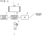
- FIG. 1 is an information processing system 1 according to an embodiment of the present invention.
- the information processing system 1 includes an auxiliary storage apparatus 2, an output apparatus 4, an input apparatus 6, a camera 7, and an information processing apparatus 10.
- the information processing apparatus 10 may be connected to an external network via an AP (Access Point) 8.
- the external network connects to a content server distributing content such as game software, and the information processing apparatus 10 can download the content from the content server via the AP 8.
- the information processing apparatus 10 according to the embodiment operates as an information processing apparatus which causes the output apparatus 4 to display a plurality of display elements such as icons.
- the input apparatus 6 has wireless or wired connection to the information processing apparatus 10.
- the input apparatus 6 receives operation input from a user and supplies operation information to the information processing apparatus 10.
- the information processing apparatus 10 according to the embodiment is a game apparatus which executes game programs, and the input apparatus 6 may be equipment such as a game controller which supplies, to the information processing apparatus 10, information regarding an operation performed by the user.
- the information processing apparatus 10 applies the operation information received from the input apparatus 6, to processing executed by the OS and processing of the game program, and causes the output apparatus 4 to output processing results.
- the information processing apparatus 10 may include a function of executing applications other than games, for example, a function of reproducing moving images of a movie or the like.
- the input apparatus 6 includes an input section having, for example, a plurality of operation pushbuttons and direction operators for specifying directions.
- the direction operators are used in a menu image to move a focus frame that encloses an icon.
- the direction operators include a plurality of arrow keys and an analog stick that can be tilted in various directions, and the plurality of arrow keys may include an up arrow key, a down arrow key, a right arrow key, and a left arrow key.
- the auxiliary storage apparatus 2 is a storage such as an HDD (Hard Disk Drive) or an SSD (Solid State Drive), and may be a built-in storage apparatus or an external storage apparatus connected to the information processing apparatus 10 by a USB (Universal Serial Bus) or the like.
- the output apparatus 4 may be a television including a display that outputs images and a speaker that outputs sound, or may be a head-mounted display.
- the camera 7 captures images of the space in which the user is present.
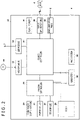
- FIG. 2 depicts a hardware configuration of the information processing apparatus 10.
- the information processing apparatus 10 includes a main power supply button 20, a power-on LED (Light Emitting Diode) 21, a standby LED 22, a system controller 24, a clock 26, a device controller 30, a medium drive 32, a USB module 34, a flash memory 36, a wireless communication module 38, a wired communication module 40, a subsystem 50, and a main system 60.
- a main power supply button 20 a power-on LED (Light Emitting Diode) 21, a standby LED 22, a system controller 24, a clock 26, a device controller 30, a medium drive 32, a USB module 34, a flash memory 36, a wireless communication module 38, a wired communication module 40, a subsystem 50, and a main system 60.
- a main power supply button 20 includes a power-on LED (Light Emitting Diode) 21, a standby LED 22, a system controller 24, a clock 26, a device controller 30, a
- the main system 60 includes a main CPU (Central Processing Unit), a memory used as a main storage device, a memory controller, a GPU (Graphics Processing Unit), and the like.
- the GPU is mainly used for arithmetic processing for game programs. These functions may be configured as a system on a chip and formed on one chip.
- the main CPU has a function of executing game programs recorded in the auxiliary storage apparatus 2 or a ROM (Read-Only Memory) medium 44.
- the subsystem 50 includes a sub-CPU, a memory used as a main storage device, a memory controller, and the like, but does not include a GPU and the function of executing the game programs.
- the sub-CPU includes fewer circuit gates than the main CPU, and has less operation consumed power than the main CPU.
- the sub-CPU operates even while the main CPU is in a standby state, and the processing functions of the sub-CPU are limited to keep power consumption low.
- the main power supply button 20 is an input section to which operation input is provided by the user, and is disposed on a front surface of a housing of the information processing apparatus 10.
- the main power supply button 20 is operated to turn on or off power supply to the main system 60 of the information processing apparatus 10.
- the power-on LED 21 emits light when the main power supply button 20 is turned on, and the standby LED 22 emits light when the main power supply button 20 is turned off.
- the system controller 24 detects that the main power supply button 20 is depressed by the user. When the main power supply button 20 is depressed while the main power supply is in an off-state, the system controller 24 acquires the depression operation as an "on-instruction.” On the other hand, when the main power supply button 20 is depressed while the main power supply is in an on-state, the system controller 24 acquires the depression operation as an "off-instruction.”
- the clock 26 is a real-time clock that generates and supplies the current date and time information to the system controller 24 or to the subsystem 50 and the main system 60.
- the device controller 30 is configured as an LSI (Large-Scale Integrated Circuit) that passes information between devices like a south bridge. As depicted in FIG. 2 , the device controller 30 is connected to the system controller 24, the medium drive 32, the USB module 34, the flash memory 36, the wireless communication module 38, the wired communication module 40, the subsystem 50, the main system 60, and other devices.
- the device controller 30 absorbs differences in electrical characteristics and data transfer speed among the devices, and controls data transfer timings.
- the medium drive 32 is a drive device on which the ROM medium 44 having application software such as games and license information recorded therein is mounted, and the medium drive 32 drives the ROM medium 44 to read programs, data, and the like from the ROM medium 44.
- the ROM medium 44 may be a read-only recording medium such as an optical disc, a magnetooptical disc, or a Blu-ray disc.
- the USB module 34 is a module connected to external equipment via a USB cable.
- the USB module 34 may be connected to the auxiliary storage apparatus 2 and the camera 7 via USB cables.
- the flash memory 36 is an auxiliary storage device constituting an internal storage.
- the wireless communication module 38 makes wireless communication with, for example, the input apparatus 6 according to a communication protocol such as the Bluetooth (registered trademark) protocol or the IEEE (Institute of Electrical and Electronics Engineers)802.11 protocol.
- the wired communication module 40 makes wired communication with external equipment and is connected to an external network via the AP 8.
- FIG. 3 depicts a functional block diagram of the information processing apparatus 10.
- the information processing apparatus 10 includes a processing unit 100 and a communication unit 102, and the processing unit 100 includes a reception section 110, a system image generation section 120, an acquisition section 130, an execution section 140, and a display control section 150.
- elements described as functional blocks performing various processing operations can be configured using circuit blocks, memories, and other LSIs, and in terms of software, the elements are implemented using system software, game programs loaded into the memory, and the like. Accordingly, a person skilled in the art can understand that the functional blocks can be implemented in a variety of forms using only hardware, only software, or a combination of software and hardware, and limitation to any of the forms is not intended.
- the communication unit 102 is expressed as a configuration including the functions of both the wireless communication module 38 and the wired communication module 40 depicted in FIG. 2 .
- the communication unit 102 receives operation information provided by the user operating the input section of the input apparatus 6, and the reception section 110 receives the operation information received by the communication unit 102.
- the system image generation section 120 has a function of generating a menu image including a plurality of display elements.
- the display elements included in the menu image may be GUI elements such as icons in games or icons in applications other than the games.
- the execution section 140 executes a function associated with the selected icon. For example, when a game icon is selected and the determination operation is performed on the game icon, the execution section 140 executes a game program associated with the selected icon, to generate a game image and a game sound.
- the display control section 150 causes the output apparatus 4 to display the game image generated by the execution section 140.
- the system image generation section 120 includes an arrangement section 122, a display processing section 124, and an identification section 126.
- the arrangement section 122 arranges a plurality of icons on two-dimensional coordinates constituting the screen, to generate a menu image.
- the arrangement section 122 generates a menu image by using any of various user operations as a trigger. For example, when an on-operation is performed on the main power supply button 20 to activate the information processing apparatus 10, the arrangement section 122 may generate a menu image, and the display control section 150 may display the menu image on the output apparatus 4.
- FIG. 4 depicts an example of the menu image.
- the menu image depicted in FIG. 4 may be an initial image displayed on the output apparatus 4 when the information processing apparatus 10 is activated.
- the arrangement section 122 generates a menu image in which a plurality of icons 200a, 200b, 200c, 200d, 200e, 200f, 200g, 200h, and 200i (hereinafter referred to as the "icons 200" in a case where the icons are not particularly distinguished from one another) are arranged.
- the arrangement section 122 may arrange the plurality of icons 200 according to a predetermined layout (format). In the embodiment, the arrangement section 122 arranges the icons 200 corresponding to GUI elements with which functions are associated. However, another type of display elements may be arranged.
- the display processing section 124 displays the icon 200 which is in the selected state, in a such manner as to indicate that the icon 200 is selected.
- the icon 200a located in an upper left corner of the screen is in the selected state.
- the display processing section 124 places, around the icon 202a, a focus frame 202 for indicating that the icon is in the selected state. By checking the icon enclosed by the focus frame 202, the user can recognize that the icon 200a is selected.
- the display processing section 124 may allow the user to recognize that the icon 200a is in the selected state, by displaying the selected icon 200a in such a manner that the icon 200a appears larger than a standard size, or causing the icon 200a to blink, for example, instead of using the focus frame 202.
- the input apparatus 6 operated by the user includes direction operators such as arrow keys and/or an analog stick.
- direction operators such as arrow keys and/or an analog stick.
- the user when moving the focus frame 202 to select the icon 200, the user operates the direction operators of the input apparatus 6.
- the direction operators may include four arrow keys allowing the user to specify four directions, that is, up, down, right, and left directions.
- the reception section 110 receives the operation of the direction operator as an operation of selecting the icon 200.
- the identification section 126 identifies the moving destination of the focus frame 202, in other words, the selected icon 200, on the basis of the arrow key operated by the user.
- FIG. 5 depicts an example of the menu image in which the focus frame 202 has moved.
- the focus frame 202 is located around the icon 200g.
- the identification section 126 identifies the icon 200g selected by the operation of the right arrow key.
- the plurality of icons 200 are arranged by the arrangement section 122 according to a predetermined layout, and the moving destination of the focus frame 202 that is set when the arrow key is operated is defined for each of the positions where the icons 200 are arranged.
- the moving destination of the focus frame 202 is defined for the upper left corner position where the icon 200a is located, as follows: the focus frame 202 moves to the position of the icon 200g when an operation of the right arrow key is made; and the focus frame 202 moves to the position of the icon 200b when an operation of the down arrow key is made. Note that, for the upper left corner position where the icon 200a is located, it is also defined that the focus frame 202 does not move when an operation of either the left arrow key or the up arrow key is made.
- the moving destination of the focus frame 202 may be defined by the angular range of the direction in which the analog stick is tilted.
- the identification section 126 identifies the position to which the focus frame 202 is to move, according to the definition information regarding the moving destination.
- the identification section 126 identifies the icon 200g selected by the operation of the right arrow key, and the display processing section 124 places the focus frame 202 around the icon 200g.
- the user can easily predict the moving destination of the focus frame 202 that is set by operation of the arrow key. For example, when the user operates the right arrow key, the focus frame 202 moves to the position located on the right of the icon. When the user operates the down arrow key, the focus frame 202 moves to the position located immediately below the icon.
- the user has difficulty in predicting the moving destination of the focus frame 202 that is set by operation of the arrow key.
- the right arrow key of the input apparatus 6 is operated to move, to the position of the icon 200g, the focus frame 202 located at the position of the icon 200a.
- the user may gaze the icon 200d after operating the right arrow key, and lose sight of the focus frame 202.
- the display processing section 124 in the embodiment performs presentation display indicating that the state in which the icon 200a is selected is to be changed to the state in which the icon 200g is selected.
- the display processing section 124 inserts, between the display of the menu image depicted in FIG. 4 and the display of the menu image depicted in FIG. 5 , a presentation indicating that the selected icon is to be changed.
- the icon 200a enclosed by the focus frame 202 that is yet to move is referred to as the "first icon 200a”
- the icon 200g enclosed by the focus frame 202 that has moved is referred to as the "second icon 200g.”
- the identification section 126 determines the moving destination of the focus frame 202 to be the position of the second icon 200g.
- the display processing section 124 performs presentation display indicating that the state in which the first icon 200a is selected is to be changed to the state in which the second icon 200g is selected. During the presentation display, the display processing section 124 does not display the focus frame 202.
- FIG. 6 depicts an example of presentation display provided when the icon 200 in the selected state is changed.
- a moving direction 204 indicates a direction heading toward the second icon 200g from the first icon 200a.
- the moving direction 204 is drawn in FIG. 6 in order to illustrate the moving direction of a presentation element 210; the moving direction 204 is not displayed as a part of the presentation display. Therefore, the user does not visually recognize the moving direction 204.
- the moving direction 204 may be displayed as a part of the presentation display in order to make the moving destination of the presentation element 210 clearer.
- the display processing section 124 performs, between the display position of the first icon 200a and the display position of the second icon 200g, the presentation display related to the direction heading toward the display position of the second icon 200g from the display position of the first icon 200a. Specifically, the display processing section 124 performs presentation display for moving the presentation element 210 between the display position of the first icon 200a and the display position of the second icon 200g.
- the presentation element 210 includes at least a high-luminance region, and the display processing section 124 causes the presentation element 210 to move at high speed in such a manner as to jump out of the first icon 200a and jump into the second icon 200g.
- FIG. 7 depicts how the presentation element 210 jumps into the second icon 200g. Since the presentation element 210 with the high-luminance region moves straight from the first icon 200a toward the second icon 200g, the user can recognize the position of the second icon 200g.
- the display processing section 124 changes the shape of the presentation element 210 from the shape of the first icon 200a to the shape of the second icon 200g.
- the shape of the presentation element 210 is substantially identical to the shape of the first icon 200a.
- the display processing section 124 gradually (continuously or stepwise) deform the presentation element 210 after the presentation element 210 leaves the display position of the first icon 200a but before the presentation element 210 reaches the display position of the second icon 200g.
- the height of the second icon 200g is longer than the height of the first icon 200a.
- the display processing section 124 gradually increases the height of the presentation element 210.
- the display processing section 124 makes the height of the presentation element 210 equal to the height of the second icon 200g.
- the display processing section 124 displays the focus frame 202 around the second icon 200g.
- the presentation element 210 moves from the display position of the first icon 200a to the display position of the second icon 200g, producing a visual effect that makes the user feel that the focus frame 202 is moving.
- the moving presentation element 210 deformed according to the shape of the first icon 200a corresponding to the moving source and the shape of the second icon 200g corresponding to the moving destination, the user can be made to strongly feel the unity of the presentation element 210 and the focus frame 202.
- the first icon 200a and the second icon 200g each have a rectangular shape but that one of or both the first icon 200a and the second icon 200g may have a shape other than the rectangle, for example, a round shape or a triangular shape. Even in that case, by deforming the moving presentation element 210 from the shape of the first icon 200a corresponding to the moving source to the shape of the second icon 200g corresponding to the moving destination, the display processing section 124 can make the user recognize pseudo movement of the focus frame 202.
- the display processing section 124 may determine the moving speed of the presentation element 210 according to the distance between the display position of the first icon 200a and the display position of the second icon 200g. Specifically, the display processing section 124 completes the presentation display in the same predetermined period of time regardless of the distance between the first icon 200a and the second icon 200g.
- the moving speed is relatively high as the distance is relatively long, whereas the moving speed is relatively short as the distance is relatively short.
- the purpose of the presentation display is to make the user recognize the second icon 200g corresponding to the moving destination.
- the moving speed during the presentation display period is set such that the speed of the presentation element 210 moving into the second icon 200g is slower than the speed of the presentation element 210 moving out from the display position of the first icon 200a, so that the user easily recognizes the second icon 200g.
- the display processing section 124 performs presentation display such that at least either the first icon 200a or the second icon 200g appears deformed in the moving direction 204. As seen in FIG. 7 , when the presentation element 210 with a shape similar to the second icon 200g is overlaid on the second icon 200g, a presentation effect is produced such that the second icon 200g is extended and deformed in the moving direction 204. Such a presentation effect allows the user to easily recognize that the second icon 200g is selected. Note that, after the presentation display, the display processing section 124 places the focus frame 202 around the second icon 200g as depicted in FIG. 5 .
- a method for displaying images such as thumbnails on the output apparatus 4 will be described below.
- the information processing apparatus 10 accesses the content server via the AP 8, and the acquisition section 130 acquires a thumbnail image of the content from the content server.
- the content server first transmits a thumbnail image with a low resolution and then transmits a thumbnail image with a high resolution such that the display control section 150 can promptly display the thumbnail image of the content on the output apparatus 4.
- thumbnail image that has the low resolution and is transmitted first is hereinafter referred to as the "first thumbnail image,” whereas the thumbnail image that has the high resolution and is subsequently transmitted is hereinafter referred to as the "second thumbnail image.”
- first thumbnail image may be an image generated by reducing the resolution and the data size of the second thumbnail image.
- the arrangement section 122 places the first thumbnail image at a predetermined position on the two-dimensional coordinates constituting the screen, and the display control section 150 displays the thumbnail image.
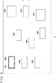
- FIG. 8 depicts a display example of four first thumbnail images.
- the first thumbnail image displayed in FIG. 8 has a low resolution, and thus, the user recognizes the displayed first thumbnail image as a coarse image. In this case, the purpose of promptly displaying the thumbnail image is achieved, but the coarse image gives a cheap impression and is thus not preferable.
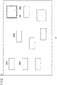
- FIG. 9 depicts a display example of the first thumbnail images in a modified example.
- the display processing section 124 displays the first thumbnail image partially concealed.
- the display processing section 124 overlays, on the first thumbnail image, a mask with a plurality of scattered openings (holes), so that the first thumbnail image is displayed only through the plurality of openings.
- a mask that includes twenty or more openings arranged at substantially regular intervals in the vertical direction and twenty or more openings arranged at substantially regular intervals in the horizontal direction is overlayed on a single first thumbnail image, the user can recognize a blurred outline of the thumbnail image.
- the modified example instead of directly displaying the entire coarse image as depicted in FIG. 8 , only a part of the coarse image is displayed to prevent the user from noticing the coarseness of the image.
- the acquisition section 130 acquires the second thumbnail image from the content server while the display control section 150 displays the first thumbnail image partially concealed
- the arrangement section 122 places, on the two-dimensional coordinates constituting the screen, the second thumbnail image instead of the first thumbnail image and the mask.
- the display control section 150 displays the second thumbnail image instead of the first thumbnail image that is partially concealed and displayed.
- An image display method in the modified example includes:
- the present invention can be utilized in a technical field in which a plurality of display elements are displayed on a screen.
Landscapes
- Engineering & Computer Science (AREA)
- General Engineering & Computer Science (AREA)
- Theoretical Computer Science (AREA)
- Human Computer Interaction (AREA)
- Physics & Mathematics (AREA)
- General Physics & Mathematics (AREA)
- User Interface Of Digital Computer (AREA)
Abstract
Description
- The present invention relates to a technology for displaying a plurality of display elements on a screen.
- An OS (Operating System) uses an icon-based GUI (Graphical User Interface) to present information to a user. When the user selects a desired icon from a menu image in which a plurality of icons are arranged, the selected icon is displayed in a manner different from that in which the other icons are displayed; for example, the selected icon is enclosed by a focus frame. When the user performs a determination operation on the selected icon, the operating system executes a function associated with the icon.
- In a case where a user selects an icon by operating arrow keys, the user has difficulty in predicting which icon position the focus frame is to move to unless the plurality of icons are regularly arranged in the vertical and horizontal directions, and the user may possibly lose sight of the focus frame. Thus, it is desired to develop a technology that allows a user to easily recognize the icon selected by the user.
- To solve the problem described above, an image processing apparatus according to an aspect of the present invention includes an arrangement section that arranges a plurality of display elements including a first display element and a second display element, a reception section that receives an operation for selecting a display element, and a display processing section that displays the selected display element in such a predetermined manner as to indicate that the display element is selected. When the reception section receives an operation for selecting the second display element while the first display element is in the selected state, the display processing section performs presentation display indicating that a state in which the first display element is selected is to be changed to a state in which the second display element is selected, and then displays the second display element in a predetermined manner.
- An image processing method according to another aspect of the present invention includes a step of arranging a plurality of display elements including a first display element and a second display element, a step of receiving an operation for selecting the second display element while the first display element is in a selected state, a step of performing presentation display indicating that a state in which the first display element is selected is to be changed to a state in which the second display element is selected, and a step of displaying the selected second display element in a predetermined manner.
- Note that any combination of the components described above and expressions obtained by exchanging the expressions of the present invention among a method, an apparatus, a system, a recording medium, a computer program, and the like are also effective as aspects of the present invention.
-
- [
FIG. 1 ]
FIG. 1 is a diagram depicting an information processing system according to an embodiment. - [
FIG. 2 ]
FIG. 2 is a diagram depicting a hardware configuration of an information processing apparatus. - [
FIG. 3 ]
FIG. 3 is a diagram depicting functional blocks of the information processing apparatus. - [
FIG. 4 ]
FIG. 4 is a diagram depicting an example of a menu image. - [
FIG. 5 ]
FIG. 5 is a diagram depicting an example of the menu image in which a focus frame has moved. - [
FIG. 6 ]
FIG. 6 is a diagram depicting an example of presentation display provided when an icon in a selected state is changed. - [
FIG. 7 ]
FIG. 7 is a diagram depicting movement of a presentation element. - [
FIG. 8 ]
FIG. 8 is a diagram depicting a display example of first thumbnail images. - [
FIG. 9 ]
FIG. 9 is a diagram depicting a display example of the first thumbnail images in a modified example. -
FIG. 1 is aninformation processing system 1 according to an embodiment of the present invention. Theinformation processing system 1 includes anauxiliary storage apparatus 2, anoutput apparatus 4, aninput apparatus 6, acamera 7, and aninformation processing apparatus 10. Theinformation processing apparatus 10 may be connected to an external network via an AP (Access Point) 8. The external network connects to a content server distributing content such as game software, and theinformation processing apparatus 10 can download the content from the content server via the AP 8. Theinformation processing apparatus 10 according to the embodiment operates as an information processing apparatus which causes theoutput apparatus 4 to display a plurality of display elements such as icons. - The
input apparatus 6 has wireless or wired connection to theinformation processing apparatus 10. Theinput apparatus 6 receives operation input from a user and supplies operation information to theinformation processing apparatus 10. Theinformation processing apparatus 10 according to the embodiment is a game apparatus which executes game programs, and theinput apparatus 6 may be equipment such as a game controller which supplies, to theinformation processing apparatus 10, information regarding an operation performed by the user. Theinformation processing apparatus 10 applies the operation information received from theinput apparatus 6, to processing executed by the OS and processing of the game program, and causes theoutput apparatus 4 to output processing results. Note that theinformation processing apparatus 10 may include a function of executing applications other than games, for example, a function of reproducing moving images of a movie or the like. - The
input apparatus 6 according to the embodiment includes an input section having, for example, a plurality of operation pushbuttons and direction operators for specifying directions. In the embodiment, the direction operators are used in a menu image to move a focus frame that encloses an icon. The direction operators include a plurality of arrow keys and an analog stick that can be tilted in various directions, and the plurality of arrow keys may include an up arrow key, a down arrow key, a right arrow key, and a left arrow key. - The
auxiliary storage apparatus 2 is a storage such as an HDD (Hard Disk Drive) or an SSD (Solid State Drive), and may be a built-in storage apparatus or an external storage apparatus connected to theinformation processing apparatus 10 by a USB (Universal Serial Bus) or the like. Theoutput apparatus 4 may be a television including a display that outputs images and a speaker that outputs sound, or may be a head-mounted display. Thecamera 7 captures images of the space in which the user is present. -
FIG. 2 depicts a hardware configuration of theinformation processing apparatus 10. Theinformation processing apparatus 10 includes a mainpower supply button 20, a power-on LED (Light Emitting Diode) 21, astandby LED 22, asystem controller 24, aclock 26, adevice controller 30, amedium drive 32, aUSB module 34, aflash memory 36, awireless communication module 38, awired communication module 40, asubsystem 50, and amain system 60. - The
main system 60 includes a main CPU (Central Processing Unit), a memory used as a main storage device, a memory controller, a GPU (Graphics Processing Unit), and the like. The GPU is mainly used for arithmetic processing for game programs. These functions may be configured as a system on a chip and formed on one chip. The main CPU has a function of executing game programs recorded in theauxiliary storage apparatus 2 or a ROM (Read-Only Memory)medium 44. - The
subsystem 50 includes a sub-CPU, a memory used as a main storage device, a memory controller, and the like, but does not include a GPU and the function of executing the game programs. The sub-CPU includes fewer circuit gates than the main CPU, and has less operation consumed power than the main CPU. The sub-CPU operates even while the main CPU is in a standby state, and the processing functions of the sub-CPU are limited to keep power consumption low. - The main
power supply button 20 is an input section to which operation input is provided by the user, and is disposed on a front surface of a housing of theinformation processing apparatus 10. The mainpower supply button 20 is operated to turn on or off power supply to themain system 60 of theinformation processing apparatus 10. The power-onLED 21 emits light when the mainpower supply button 20 is turned on, and thestandby LED 22 emits light when the mainpower supply button 20 is turned off. - The
system controller 24 detects that the mainpower supply button 20 is depressed by the user. When the mainpower supply button 20 is depressed while the main power supply is in an off-state, thesystem controller 24 acquires the depression operation as an "on-instruction." On the other hand, when the mainpower supply button 20 is depressed while the main power supply is in an on-state, thesystem controller 24 acquires the depression operation as an "off-instruction." - The
clock 26 is a real-time clock that generates and supplies the current date and time information to thesystem controller 24 or to thesubsystem 50 and themain system 60. Thedevice controller 30 is configured as an LSI (Large-Scale Integrated Circuit) that passes information between devices like a south bridge. As depicted inFIG. 2 , thedevice controller 30 is connected to thesystem controller 24, themedium drive 32, theUSB module 34, theflash memory 36, thewireless communication module 38, thewired communication module 40, thesubsystem 50, themain system 60, and other devices. Thedevice controller 30 absorbs differences in electrical characteristics and data transfer speed among the devices, and controls data transfer timings. - The
medium drive 32 is a drive device on which theROM medium 44 having application software such as games and license information recorded therein is mounted, and themedium drive 32 drives theROM medium 44 to read programs, data, and the like from theROM medium 44. TheROM medium 44 may be a read-only recording medium such as an optical disc, a magnetooptical disc, or a Blu-ray disc. - The
USB module 34 is a module connected to external equipment via a USB cable. TheUSB module 34 may be connected to theauxiliary storage apparatus 2 and thecamera 7 via USB cables. Theflash memory 36 is an auxiliary storage device constituting an internal storage. Thewireless communication module 38 makes wireless communication with, for example, theinput apparatus 6 according to a communication protocol such as the Bluetooth (registered trademark) protocol or the IEEE (Institute of Electrical and Electronics Engineers)802.11 protocol. Thewired communication module 40 makes wired communication with external equipment and is connected to an external network via theAP 8. -
FIG. 3 depicts a functional block diagram of theinformation processing apparatus 10. Theinformation processing apparatus 10 includes aprocessing unit 100 and acommunication unit 102, and theprocessing unit 100 includes areception section 110, a systemimage generation section 120, anacquisition section 130, anexecution section 140, and adisplay control section 150. - In
FIG. 3 , in terms of hardware, elements described as functional blocks performing various processing operations can be configured using circuit blocks, memories, and other LSIs, and in terms of software, the elements are implemented using system software, game programs loaded into the memory, and the like. Accordingly, a person skilled in the art can understand that the functional blocks can be implemented in a variety of forms using only hardware, only software, or a combination of software and hardware, and limitation to any of the forms is not intended. - The
communication unit 102 is expressed as a configuration including the functions of both thewireless communication module 38 and thewired communication module 40 depicted inFIG. 2 . Thecommunication unit 102 receives operation information provided by the user operating the input section of theinput apparatus 6, and thereception section 110 receives the operation information received by thecommunication unit 102. - The system
image generation section 120 has a function of generating a menu image including a plurality of display elements. In the embodiment, the display elements included in the menu image may be GUI elements such as icons in games or icons in applications other than the games. When the user selects a display element from the menu image and performs a determination operation on the selected display element, theexecution section 140 executes a function associated with the selected icon. For example, when a game icon is selected and the determination operation is performed on the game icon, theexecution section 140 executes a game program associated with the selected icon, to generate a game image and a game sound. At this time, thedisplay control section 150 causes theoutput apparatus 4 to display the game image generated by theexecution section 140. - The system
image generation section 120 includes anarrangement section 122, adisplay processing section 124, and anidentification section 126. Thearrangement section 122 arranges a plurality of icons on two-dimensional coordinates constituting the screen, to generate a menu image. Thearrangement section 122 generates a menu image by using any of various user operations as a trigger. For example, when an on-operation is performed on the mainpower supply button 20 to activate theinformation processing apparatus 10, thearrangement section 122 may generate a menu image, and thedisplay control section 150 may display the menu image on theoutput apparatus 4. -
FIG. 4 depicts an example of the menu image. The menu image depicted inFIG. 4 may be an initial image displayed on theoutput apparatus 4 when theinformation processing apparatus 10 is activated. Thearrangement section 122 generates a menu image in which a plurality oficons arrangement section 122 may arrange the plurality of icons 200 according to a predetermined layout (format). In the embodiment, thearrangement section 122 arranges the icons 200 corresponding to GUI elements with which functions are associated. However, another type of display elements may be arranged. - The
display processing section 124 displays the icon 200 which is in the selected state, in a such manner as to indicate that the icon 200 is selected. In the initial image depicted inFIG. 4 , theicon 200a located in an upper left corner of the screen is in the selected state. Thedisplay processing section 124 places, around the icon 202a, afocus frame 202 for indicating that the icon is in the selected state. By checking the icon enclosed by thefocus frame 202, the user can recognize that theicon 200a is selected. Note that thedisplay processing section 124 may allow the user to recognize that theicon 200a is in the selected state, by displaying the selectedicon 200a in such a manner that theicon 200a appears larger than a standard size, or causing theicon 200a to blink, for example, instead of using thefocus frame 202. - The
input apparatus 6 operated by the user includes direction operators such as arrow keys and/or an analog stick. In the embodiment, when moving thefocus frame 202 to select the icon 200, the user operates the direction operators of theinput apparatus 6. The direction operators may include four arrow keys allowing the user to specify four directions, that is, up, down, right, and left directions. - With the menu image being displayed on the
output apparatus 4, when the user operates any of the direction operators of theinput apparatus 6, thereception section 110 receives the operation of the direction operator as an operation of selecting the icon 200. Theidentification section 126 identifies the moving destination of thefocus frame 202, in other words, the selected icon 200, on the basis of the arrow key operated by the user. -
FIG. 5 depicts an example of the menu image in which thefocus frame 202 has moved. In the menu image depicted inFIG. 5 , thefocus frame 202 is located around theicon 200g. In the menu image depicted inFIG. 4 , when thereception section 110 receives the operation of the right arrow key, theidentification section 126 identifies theicon 200g selected by the operation of the right arrow key. - The plurality of icons 200 are arranged by the
arrangement section 122 according to a predetermined layout, and the moving destination of thefocus frame 202 that is set when the arrow key is operated is defined for each of the positions where the icons 200 are arranged. For example, the moving destination of thefocus frame 202 is defined for the upper left corner position where theicon 200a is located, as follows: thefocus frame 202 moves to the position of theicon 200g when an operation of the right arrow key is made; and thefocus frame 202 moves to the position of theicon 200b when an operation of the down arrow key is made. Note that, for the upper left corner position where theicon 200a is located, it is also defined that thefocus frame 202 does not move when an operation of either the left arrow key or the up arrow key is made. - There has been described definition information related to the moving destination that is set when the direction operators are the up, down, right, and left arrow keys. However, in a case where an analog stick is used as the direction operator, the moving destination of the
focus frame 202 may be defined by the angular range of the direction in which the analog stick is tilted. - The
identification section 126 identifies the position to which thefocus frame 202 is to move, according to the definition information regarding the moving destination. In the menu image depicted inFIG. 4 , when thereception section 110 receives the operation of the right arrow key, theidentification section 126 identifies theicon 200g selected by the operation of the right arrow key, and thedisplay processing section 124 places thefocus frame 202 around theicon 200g. - In a case where the plurality of icons 200 are regularly arranged in the vertical direction and the horizontal direction, the user can easily predict the moving destination of the
focus frame 202 that is set by operation of the arrow key. For example, when the user operates the right arrow key, thefocus frame 202 moves to the position located on the right of the icon. When the user operates the down arrow key, thefocus frame 202 moves to the position located immediately below the icon. - On the other hand, as depicted in
FIGS. 4 and5 , in a case where the plurality of icons 200 are somewhat irregularly arranged, the user has difficulty in predicting the moving destination of thefocus frame 202 that is set by operation of the arrow key. In the embodiment, the right arrow key of theinput apparatus 6 is operated to move, to the position of theicon 200g, thefocus frame 202 located at the position of theicon 200a. However, in a case where the user assumes that thefocus frame 202 is to move to the position of theicon 200d, the user may gaze theicon 200d after operating the right arrow key, and lose sight of thefocus frame 202. - Thus, before displaying the
focus frame 202 around theicon 200g, thedisplay processing section 124 in the embodiment performs presentation display indicating that the state in which theicon 200a is selected is to be changed to the state in which theicon 200g is selected. In other words, thedisplay processing section 124 inserts, between the display of the menu image depicted inFIG. 4 and the display of the menu image depicted inFIG. 5 , a presentation indicating that the selected icon is to be changed. For the sake of explanation, theicon 200a enclosed by thefocus frame 202 that is yet to move is referred to as the "first icon 200a," and theicon 200g enclosed by thefocus frame 202 that has moved is referred to as the "second icon 200g." - In the state in which the
first icon 200a is selected (seeFIG. 4 ), when thereception section 110 receives an operation for selecting thesecond icon 200g, theidentification section 126 determines the moving destination of thefocus frame 202 to be the position of thesecond icon 200g. At this time, thedisplay processing section 124 performs presentation display indicating that the state in which thefirst icon 200a is selected is to be changed to the state in which thesecond icon 200g is selected. During the presentation display, thedisplay processing section 124 does not display thefocus frame 202. -
FIG. 6 depicts an example of presentation display provided when the icon 200 in the selected state is changed. InFIG. 6 , a movingdirection 204 indicates a direction heading toward thesecond icon 200g from thefirst icon 200a. The movingdirection 204 is drawn inFIG. 6 in order to illustrate the moving direction of apresentation element 210; the movingdirection 204 is not displayed as a part of the presentation display. Therefore, the user does not visually recognize the movingdirection 204. However, the movingdirection 204 may be displayed as a part of the presentation display in order to make the moving destination of thepresentation element 210 clearer. - The
display processing section 124 performs, between the display position of thefirst icon 200a and the display position of thesecond icon 200g, the presentation display related to the direction heading toward the display position of thesecond icon 200g from the display position of thefirst icon 200a. Specifically, thedisplay processing section 124 performs presentation display for moving thepresentation element 210 between the display position of thefirst icon 200a and the display position of thesecond icon 200g. Thepresentation element 210 includes at least a high-luminance region, and thedisplay processing section 124 causes thepresentation element 210 to move at high speed in such a manner as to jump out of thefirst icon 200a and jump into thesecond icon 200g. -
FIG. 7 depicts how thepresentation element 210 jumps into thesecond icon 200g. Since thepresentation element 210 with the high-luminance region moves straight from thefirst icon 200a toward thesecond icon 200g, the user can recognize the position of thesecond icon 200g. - The
display processing section 124 changes the shape of thepresentation element 210 from the shape of thefirst icon 200a to the shape of thesecond icon 200g. When thepresentation element 210 jumps out of thefirst icon 200a, the shape of thepresentation element 210 is substantially identical to the shape of thefirst icon 200a. When thepresentation element 210 jumps into thesecond icon 200g, the shape of thepresentation element 210 is substantially identical to the shape of thesecond icon 200g. It is preferable that thedisplay processing section 124 gradually (continuously or stepwise) deform thepresentation element 210 after thepresentation element 210 leaves the display position of thefirst icon 200a but before thepresentation element 210 reaches the display position of thesecond icon 200g. - As depicted in
FIGS. 6 and7 , the height of thesecond icon 200g is longer than the height of thefirst icon 200a. Thus, when moving thepresentation element 210 from the display position of thefirst icon 200a to the display position of thesecond icon 200g, thedisplay processing section 124 gradually increases the height of thepresentation element 210. When thepresentation element 210 is overlaid on thesecond icon 200g, thedisplay processing section 124 makes the height of thepresentation element 210 equal to the height of thesecond icon 200g. After overlaying thepresentation element 210 with the high-luminance region on thesecond icon 200g, thedisplay processing section 124 displays thefocus frame 202 around thesecond icon 200g. - The
presentation element 210 moves from the display position of thefirst icon 200a to the display position of thesecond icon 200g, producing a visual effect that makes the user feel that thefocus frame 202 is moving. At this time, with the movingpresentation element 210 deformed according to the shape of thefirst icon 200a corresponding to the moving source and the shape of thesecond icon 200g corresponding to the moving destination, the user can be made to strongly feel the unity of thepresentation element 210 and thefocus frame 202. - Note that, in the embodiment, the
first icon 200a and thesecond icon 200g each have a rectangular shape but that one of or both thefirst icon 200a and thesecond icon 200g may have a shape other than the rectangle, for example, a round shape or a triangular shape. Even in that case, by deforming the movingpresentation element 210 from the shape of thefirst icon 200a corresponding to the moving source to the shape of thesecond icon 200g corresponding to the moving destination, thedisplay processing section 124 can make the user recognize pseudo movement of thefocus frame 202. - The
display processing section 124 may determine the moving speed of thepresentation element 210 according to the distance between the display position of thefirst icon 200a and the display position of thesecond icon 200g. Specifically, thedisplay processing section 124 completes the presentation display in the same predetermined period of time regardless of the distance between thefirst icon 200a and thesecond icon 200g. Thus, the moving speed is relatively high as the distance is relatively long, whereas the moving speed is relatively short as the distance is relatively short. Note that the purpose of the presentation display is to make the user recognize thesecond icon 200g corresponding to the moving destination. Thus, preferably, the moving speed during the presentation display period is set such that the speed of thepresentation element 210 moving into thesecond icon 200g is slower than the speed of thepresentation element 210 moving out from the display position of thefirst icon 200a, so that the user easily recognizes thesecond icon 200g. - The
display processing section 124 performs presentation display such that at least either thefirst icon 200a or thesecond icon 200g appears deformed in the movingdirection 204. As seen inFIG. 7 , when thepresentation element 210 with a shape similar to thesecond icon 200g is overlaid on thesecond icon 200g, a presentation effect is produced such that thesecond icon 200g is extended and deformed in the movingdirection 204. Such a presentation effect allows the user to easily recognize that thesecond icon 200g is selected. Note that, after the presentation display, thedisplay processing section 124 places thefocus frame 202 around thesecond icon 200g as depicted inFIG. 5 . - The present invention has been described on the basis of the embodiment. The embodiment is illustrative, and a person skilled in the art may understand that a variety of modified examples can be provided by combining components and processes of the embodiment and that such modified examples are also within the scope of the present invention.
- A method for displaying images such as thumbnails on the
output apparatus 4 will be described below. When the user purchases content such as a game from the content server, theinformation processing apparatus 10 accesses the content server via theAP 8, and theacquisition section 130 acquires a thumbnail image of the content from the content server. At this time, the content server according to the embodiment first transmits a thumbnail image with a low resolution and then transmits a thumbnail image with a high resolution such that thedisplay control section 150 can promptly display the thumbnail image of the content on theoutput apparatus 4. The thumbnail image that has the low resolution and is transmitted first is hereinafter referred to as the "first thumbnail image," whereas the thumbnail image that has the high resolution and is subsequently transmitted is hereinafter referred to as the "second thumbnail image." Note that the first thumbnail image may be an image generated by reducing the resolution and the data size of the second thumbnail image. - When the
acquisition section 130 acquires the first thumbnail image, thearrangement section 122 places the first thumbnail image at a predetermined position on the two-dimensional coordinates constituting the screen, and thedisplay control section 150 displays the thumbnail image. -
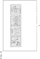
FIG. 8 depicts a display example of four first thumbnail images. The first thumbnail image displayed inFIG. 8 has a low resolution, and thus, the user recognizes the displayed first thumbnail image as a coarse image. In this case, the purpose of promptly displaying the thumbnail image is achieved, but the coarse image gives a cheap impression and is thus not preferable. -
FIG. 9 depicts a display example of the first thumbnail images in a modified example. Thedisplay processing section 124 displays the first thumbnail image partially concealed. In the example inFIG. 9 , thedisplay processing section 124 overlays, on the first thumbnail image, a mask with a plurality of scattered openings (holes), so that the first thumbnail image is displayed only through the plurality of openings. For example, when a mask that includes twenty or more openings arranged at substantially regular intervals in the vertical direction and twenty or more openings arranged at substantially regular intervals in the horizontal direction is overlayed on a single first thumbnail image, the user can recognize a blurred outline of the thumbnail image. Thus, in the modified example, instead of directly displaying the entire coarse image as depicted inFIG. 8 , only a part of the coarse image is displayed to prevent the user from noticing the coarseness of the image. - When the
acquisition section 130 acquires the second thumbnail image from the content server while thedisplay control section 150 displays the first thumbnail image partially concealed, thearrangement section 122 places, on the two-dimensional coordinates constituting the screen, the second thumbnail image instead of the first thumbnail image and the mask. Thus, thedisplay control section 150 displays the second thumbnail image instead of the first thumbnail image that is partially concealed and displayed. The above-described processing enables theinformation processing apparatus 10 to display the entire second thumbnail image with the high resolution after promptly displaying only a part of the first thumbnail image with the low resolution. - An outline of the above-described modified example is as follows.
An image display method in the modified example includes: - a step of acquiring a first image with a low resolution;
- a step of partially concealing the acquired first image and
- displaying the first image;
- a step of acquiring a second image with a high resolution; and
- a step of displaying the second image instead of the first image.
- The present invention can be utilized in a technical field in which a plurality of display elements are displayed on a screen.
-
- 1:
- Information processing system
- 10:
- Information processing apparatus
- 100:
- Processing unit
- 102:
- Communication unit
- 110:
- Reception section
- 120:
- System image generation section
- 122:
- Arrangement section
- 124:
- Display processing section
- 126:
- Identification section
- 130:
- Acquisition section
- 140:
- Execution section
- 150:
- Display control section
Claims (8)
- An image processing apparatus comprising:an arrangement section that arranges a plurality of display elements including a first display element and a second display element;a reception section that receives an operation for selecting a display element; anda display processing section that displays the selected display element in such a predetermined manner as to indicate that the display element is selected, wherein,when the reception section receives an operation for selecting the second display element while the first display element is in the selected state, the display processing section performs presentation display indicating that a state in which the first display element is selected is to be changed to a state in which the second display element is selected, and then displays the second display element in a predetermined manner.
- The image processing apparatus according to claim 1, wherein the display processing section performs, between the first display element and the second display element, presentation display related to a direction heading toward the second display element from the first display element, and then displays the second display element in the predetermined manner.
- The image processing apparatus according to claim 2, wherein the display processing section performs presentation display in which at least either the first display element or the second display element appears deformed in the direction.
- The image processing apparatus according to any one of claims 1 to 3, wherein the display processing section performs presentation display in which a presentation element is moved between a display position of the first display element and a display position of the second display element.
- The image processing apparatus according to claim 4, wherein the display processing section changes a shape of the presentation element from a shape of the first display element to a shape of the second display element.
- The image processing apparatus according to claim 4 or 5, wherein
the display processing section determines a moving speed of the presentation element according to a distance between the display position of the first display element and the display position of the second display element. - An image processing method comprising:a step of arranging a plurality of display elements including a first display element and a second display element;a step of receiving an operation for selecting the second display element while the first display element is in a selected state;a step of performing presentation display indicating that a state in which the first display element is selected is to be changed to a state in which the second display element is selected; anda step of displaying the selected second display element in a predetermined manner.
- A program for causing a computer to implement:a function of arranging a plurality of display elements including a first display element and a second display element;a function of receiving an operation for selecting the second display element while the first display element is in a selected state;a function of performing presentation display indicating that a state in which the first display element is selected is to be changed to a state in which the second display element is selected; anda function of displaying the selected second display element in a predetermined manner.
Applications Claiming Priority (2)
| Application Number | Priority Date | Filing Date | Title |
|---|---|---|---|
| JP2020011904A JP7504603B2 (en) | 2020-01-28 | 2020-01-28 | Image processing device and image processing method |
| PCT/JP2020/036726 WO2021152911A1 (en) | 2020-01-28 | 2020-09-28 | Image processing device and image processing method |
Publications (2)
| Publication Number | Publication Date |
|---|---|
| EP4099143A1 true EP4099143A1 (en) | 2022-12-07 |
| EP4099143A4 EP4099143A4 (en) | 2024-02-28 |
Family
ID=77079680
Family Applications (1)
| Application Number | Title | Priority Date | Filing Date |
|---|---|---|---|
| EP20916732.9A Pending EP4099143A4 (en) | 2020-01-28 | 2020-09-28 | IMAGE PROCESSING DEVICE AND IMAGE PROCESSING METHOD |
Country Status (4)
| Country | Link |
|---|---|
| US (1) | US11880548B2 (en) |
| EP (1) | EP4099143A4 (en) |
| JP (1) | JP7504603B2 (en) |
| WO (1) | WO2021152911A1 (en) |
Family Cites Families (13)
| Publication number | Priority date | Publication date | Assignee | Title |
|---|---|---|---|---|
| JPS6440018A (en) | 1987-08-06 | 1989-02-10 | Hidemi Jutaku Kk | Toilet bowl |
| US5687331A (en) * | 1995-08-03 | 1997-11-11 | Microsoft Corporation | Method and system for displaying an animated focus item |
| JPH1040018A (en) * | 1996-04-24 | 1998-02-13 | Sharp Corp | Mouse cursor control device and recording medium recording mouse cursor control program |
| JP2001155188A (en) | 1999-09-14 | 2001-06-08 | Sony Computer Entertainment Inc | Method of selectively receiving display object, storage medium and program execution device |
| US8250490B2 (en) * | 2006-12-18 | 2012-08-21 | Canon Kabushiki Kaisha | Display image control apparatus |
| US9003326B2 (en) * | 2008-09-23 | 2015-04-07 | Apple Inc. | Indicating input focus by showing focus transitions |
| US9021386B1 (en) * | 2009-05-28 | 2015-04-28 | Google Inc. | Enhanced user interface scrolling system |
| JP4991829B2 (en) * | 2009-11-09 | 2012-08-01 | 株式会社デンソー | Display control device for remote operation device |
| JP5029683B2 (en) * | 2009-12-29 | 2012-09-19 | コニカミノルタビジネステクノロジーズ株式会社 | Image processing apparatus, display control method for the same, and display control program |
| JP5659829B2 (en) | 2010-09-03 | 2015-01-28 | 株式会社デンソーウェーブ | Input control device for touch panel type input terminal |
| EP2664983A3 (en) * | 2012-05-17 | 2018-01-03 | LG Electronics, Inc. | Mobile terminal and control method therefor |
| US10120540B2 (en) * | 2013-03-14 | 2018-11-06 | Samsung Electronics Co., Ltd. | Visual feedback for user interface navigation on television system |
| DE102018202657A1 (en) * | 2018-02-22 | 2019-08-22 | Bayerische Motoren Werke Aktiengesellschaft | DEVICE AND METHOD FOR CONTROLLING VEHICLE FUNCTIONS AND VEHICLE |
-
2020
- 2020-01-28 JP JP2020011904A patent/JP7504603B2/en active Active
- 2020-09-28 US US17/792,204 patent/US11880548B2/en active Active
- 2020-09-28 WO PCT/JP2020/036726 patent/WO2021152911A1/en not_active Ceased
- 2020-09-28 EP EP20916732.9A patent/EP4099143A4/en active Pending
Also Published As
| Publication number | Publication date |
|---|---|
| US11880548B2 (en) | 2024-01-23 |
| EP4099143A4 (en) | 2024-02-28 |
| US20230050265A1 (en) | 2023-02-16 |
| JP2021117839A (en) | 2021-08-10 |
| WO2021152911A1 (en) | 2021-08-05 |
| JP7504603B2 (en) | 2024-06-24 |
Similar Documents
| Publication | Publication Date | Title |
|---|---|---|
| KR102006598B1 (en) | Management of the channel bar | |
| US20140223490A1 (en) | Apparatus and method for intuitive user interaction between multiple devices | |
| US20170364166A1 (en) | User terminal device and method for controlling the user terminal device thereof | |
| KR20170126295A (en) | Head mounted display device and method for controlling the same | |
| TWI710249B (en) | Head mounted display system switchable between a first-person perspective mode and a third-person perspective mode, related method and related computer readable storage medium | |
| KR20130056669A (en) | Method and apparatus for providing 3d polyhedron user interface | |
| KR101803311B1 (en) | Display appratus and Method for providing User interface thereof | |
| JP2024514771A (en) | Method for adjusting the position of an operating control, its device, terminal, and computer program | |
| CN118732838A (en) | Exclusive mode conversion | |
| TWI707575B (en) | Head mounted display capable of displaying a virtual scene and a map of a real environment, related method and related computer readable storage medium | |
| JP6153450B2 (en) | Information processing system and information processing apparatus | |
| JP2019114050A (en) | Processing device, display system, and program | |
| WO2021128929A1 (en) | Image rendering method for panorama application, and terminal device | |
| TW202324067A (en) | Method for operating mirrored content under mirror mode and computer readable storage medium | |
| CN110020300B (en) | A browser page synthesis method and terminal | |
| CN117462955A (en) | Game editing method, device and electronic device | |
| JP2014513357A (en) | Laser diode mode | |
| CN107168667B (en) | Display system with picture-in-picture display capability | |
| CN107924272B (en) | Information processing apparatus, information processing method, and program | |
| US11880548B2 (en) | Image processing apparatus and image processing method | |
| CN114500979B (en) | Display equipment, control equipment and synchronization calibration methods | |
| JP2020062376A (en) | Information processor and program | |
| CN108140357B (en) | Information processing apparatus | |
| CN116421976A (en) | Processing method, device, equipment and storage medium of virtual props | |
| US20230114438A1 (en) | Image processing apparatus and image processing method |
Legal Events
| Date | Code | Title | Description |
|---|---|---|---|
| STAA | Information on the status of an ep patent application or granted ep patent |
Free format text: STATUS: THE INTERNATIONAL PUBLICATION HAS BEEN MADE |
|
| PUAI | Public reference made under article 153(3) epc to a published international application that has entered the european phase |
Free format text: ORIGINAL CODE: 0009012 |
|
| STAA | Information on the status of an ep patent application or granted ep patent |
Free format text: STATUS: REQUEST FOR EXAMINATION WAS MADE |
|
| 17P | Request for examination filed |
Effective date: 20220721 |
|
| AK | Designated contracting states |
Kind code of ref document: A1 Designated state(s): AL AT BE BG CH CY CZ DE DK EE ES FI FR GB GR HR HU IE IS IT LI LT LU LV MC MK MT NL NO PL PT RO RS SE SI SK SM TR |
|
| DAV | Request for validation of the european patent (deleted) | ||
| DAX | Request for extension of the european patent (deleted) | ||
| A4 | Supplementary search report drawn up and despatched |
Effective date: 20240125 |
|
| RIC1 | Information provided on ipc code assigned before grant |
Ipc: G06F 3/04892 20220101ALI20240119BHEP Ipc: G06F 3/04842 20220101ALI20240119BHEP Ipc: G06F 3/0481 20220101AFI20240119BHEP |
|
| STAA | Information on the status of an ep patent application or granted ep patent |
Free format text: STATUS: EXAMINATION IS IN PROGRESS |
|
| 17Q | First examination report despatched |
Effective date: 20240506 |