EP4099129A1 - Portable electronic device - Google Patents
Portable electronic device Download PDFInfo
- Publication number
- EP4099129A1 EP4099129A1 EP22157107.8A EP22157107A EP4099129A1 EP 4099129 A1 EP4099129 A1 EP 4099129A1 EP 22157107 A EP22157107 A EP 22157107A EP 4099129 A1 EP4099129 A1 EP 4099129A1
- Authority
- EP
- European Patent Office
- Prior art keywords
- end part
- positioning
- support shaft
- electronic device
- portable electronic
- Prior art date
- Legal status (The legal status is an assumption and is not a legal conclusion. Google has not performed a legal analysis and makes no representation as to the accuracy of the status listed.)
- Granted
Links
Images


Classifications
-
- G—PHYSICS
- G06—COMPUTING OR CALCULATING; COUNTING
- G06F—ELECTRIC DIGITAL DATA PROCESSING
- G06F1/00—Details not covered by groups G06F3/00 - G06F13/00 and G06F21/00
- G06F1/16—Constructional details or arrangements
- G06F1/1613—Constructional details or arrangements for portable computers
- G06F1/1633—Constructional details or arrangements of portable computers not specific to the type of enclosures covered by groups G06F1/1615 - G06F1/1626
- G06F1/1675—Miscellaneous details related to the relative movement between the different enclosures or enclosure parts
- G06F1/1681—Details related solely to hinges
-
- G—PHYSICS
- G06—COMPUTING OR CALCULATING; COUNTING
- G06F—ELECTRIC DIGITAL DATA PROCESSING
- G06F1/00—Details not covered by groups G06F3/00 - G06F13/00 and G06F21/00
- G06F1/16—Constructional details or arrangements
- G06F1/1613—Constructional details or arrangements for portable computers
- G06F1/1615—Constructional details or arrangements for portable computers with several enclosures having relative motions, each enclosure supporting at least one I/O or computing function
- G06F1/1616—Constructional details or arrangements for portable computers with several enclosures having relative motions, each enclosure supporting at least one I/O or computing function with folding flat displays, e.g. laptop computers or notebooks having a clamshell configuration, with body parts pivoting to an open position around an axis parallel to the plane they define in closed position
- G06F1/1618—Constructional details or arrangements for portable computers with several enclosures having relative motions, each enclosure supporting at least one I/O or computing function with folding flat displays, e.g. laptop computers or notebooks having a clamshell configuration, with body parts pivoting to an open position around an axis parallel to the plane they define in closed position the display being foldable up to the back of the other housing with a single degree of freedom, e.g. by 360° rotation over the axis defined by the rear edge of the base enclosure
-
- G—PHYSICS
- G06—COMPUTING OR CALCULATING; COUNTING
- G06F—ELECTRIC DIGITAL DATA PROCESSING
- G06F1/00—Details not covered by groups G06F3/00 - G06F13/00 and G06F21/00
- G06F1/16—Constructional details or arrangements
- G06F1/1613—Constructional details or arrangements for portable computers
- G06F1/1615—Constructional details or arrangements for portable computers with several enclosures having relative motions, each enclosure supporting at least one I/O or computing function
- G06F1/1616—Constructional details or arrangements for portable computers with several enclosures having relative motions, each enclosure supporting at least one I/O or computing function with folding flat displays, e.g. laptop computers or notebooks having a clamshell configuration, with body parts pivoting to an open position around an axis parallel to the plane they define in closed position
-
- G—PHYSICS
- G06—COMPUTING OR CALCULATING; COUNTING
- G06F—ELECTRIC DIGITAL DATA PROCESSING
- G06F1/00—Details not covered by groups G06F3/00 - G06F13/00 and G06F21/00
- G06F1/16—Constructional details or arrangements
- G06F1/1613—Constructional details or arrangements for portable computers
- G06F1/1633—Constructional details or arrangements of portable computers not specific to the type of enclosures covered by groups G06F1/1615 - G06F1/1626
- G06F1/1637—Details related to the display arrangement, including those related to the mounting of the display in the housing
-
- G—PHYSICS
- G06—COMPUTING OR CALCULATING; COUNTING
- G06F—ELECTRIC DIGITAL DATA PROCESSING
- G06F1/00—Details not covered by groups G06F3/00 - G06F13/00 and G06F21/00
- G06F1/16—Constructional details or arrangements
- G06F1/1613—Constructional details or arrangements for portable computers
- G06F1/1633—Constructional details or arrangements of portable computers not specific to the type of enclosures covered by groups G06F1/1615 - G06F1/1626
- G06F1/1637—Details related to the display arrangement, including those related to the mounting of the display in the housing
- G06F1/1643—Details related to the display arrangement, including those related to the mounting of the display in the housing the display being associated to a digitizer, e.g. laptops that can be used as penpads
-
- G—PHYSICS
- G06—COMPUTING OR CALCULATING; COUNTING
- G06F—ELECTRIC DIGITAL DATA PROCESSING
- G06F1/00—Details not covered by groups G06F3/00 - G06F13/00 and G06F21/00
- G06F1/16—Constructional details or arrangements
- G06F1/1613—Constructional details or arrangements for portable computers
- G06F1/1633—Constructional details or arrangements of portable computers not specific to the type of enclosures covered by groups G06F1/1615 - G06F1/1626
- G06F1/1656—Details related to functional adaptations of the enclosure, e.g. to provide protection against EMI, shock, water, or to host detachable peripherals like a mouse or removable expansions units like PCMCIA cards, or to provide access to internal components for maintenance or to removable storage supports like CDs or DVDs, or to mechanically mount accessories
- G06F1/166—Details related to functional adaptations of the enclosure, e.g. to provide protection against EMI, shock, water, or to host detachable peripherals like a mouse or removable expansions units like PCMCIA cards, or to provide access to internal components for maintenance or to removable storage supports like CDs or DVDs, or to mechanically mount accessories related to integrated arrangements for adjusting the position of the main body with respect to the supporting surface, e.g. legs for adjusting the tilt angle
-
- G—PHYSICS
- G06—COMPUTING OR CALCULATING; COUNTING
- G06F—ELECTRIC DIGITAL DATA PROCESSING
- G06F1/00—Details not covered by groups G06F3/00 - G06F13/00 and G06F21/00
- G06F1/16—Constructional details or arrangements
- G06F1/1613—Constructional details or arrangements for portable computers
- G06F1/1633—Constructional details or arrangements of portable computers not specific to the type of enclosures covered by groups G06F1/1615 - G06F1/1626
- G06F1/1675—Miscellaneous details related to the relative movement between the different enclosures or enclosure parts
- G06F1/1679—Miscellaneous details related to the relative movement between the different enclosures or enclosure parts for locking or maintaining the movable parts of the enclosure in a fixed position, e.g. latching mechanism at the edge of the display in a laptop or for the screen protective cover of a PDA
-
- H—ELECTRICITY
- H04—ELECTRIC COMMUNICATION TECHNIQUE
- H04M—TELEPHONIC COMMUNICATION
- H04M1/00—Substation equipment, e.g. for use by subscribers
- H04M1/02—Constructional features of telephone sets
- H04M1/0202—Portable telephone sets, e.g. cordless phones, mobile phones or bar type handsets
- H04M1/0206—Portable telephones comprising a plurality of mechanically joined movable body parts, e.g. hinged housings
- H04M1/0208—Portable telephones comprising a plurality of mechanically joined movable body parts, e.g. hinged housings characterized by the relative motions of the body parts
- H04M1/0214—Foldable telephones, i.e. with body parts pivoting to an open position around an axis parallel to the plane they define in closed position
- H04M1/0216—Foldable in one direction, i.e. using a one degree of freedom hinge
-
- H—ELECTRICITY
- H04—ELECTRIC COMMUNICATION TECHNIQUE
- H04M—TELEPHONIC COMMUNICATION
- H04M1/00—Substation equipment, e.g. for use by subscribers
- H04M1/02—Constructional features of telephone sets
- H04M1/0202—Portable telephone sets, e.g. cordless phones, mobile phones or bar type handsets
- H04M1/0206—Portable telephones comprising a plurality of mechanically joined movable body parts, e.g. hinged housings
- H04M1/0208—Portable telephones comprising a plurality of mechanically joined movable body parts, e.g. hinged housings characterized by the relative motions of the body parts
- H04M1/0235—Slidable or telescopic telephones, i.e. with a relative translation movement of the body parts; Telephones using a combination of translation and other relative motions of the body parts
- H04M1/0237—Sliding mechanism with one degree of freedom
Definitions
- the disclosure relates to an electronic device, and in particular to a portable electronic device.
- a laptop is formed by a first body and a second body.
- the first body has the ability to perform logical operations and data access
- the second body has the ability to display images.
- a user may adjust the spread angle of the second body relative to the first body according to personal needs. Take a 360-degree flip laptop as an example.
- the spread angle of the second body relative to the first body is greater than or equal to 270 degrees
- the first body may be placed flat on the desktop, and the second body may be placed vertically on the desktop for the user to view or operate the second body. Since the second body is unsupported, when the user's finger or stylus touches the second body, the second body shakes or even tilts, causing inconvenience and difficulties in operation for the user.
- the disclosure provides a portable electronic device which provides convenience and stability in operation.
- the disclosure proposes a portable electronic device including a first body, a second body, and a supporting mechanism.
- the first body has a bottom surface and an opening located at the bottom surface.
- the second body is pivoted to the first body and has a rear surface and a magnetic part located at the rear surface.
- the supporting mechanism is disposed in the first body corresponding to the opening.
- the supporting mechanism includes a support shaft, a magnetic element, and a positioning stand.
- the support shaft has a first end part and a second end part opposite to the first end part.
- the positioning stand has a slide rail and multiple positioning protrusions. The positioning protrusions are arranged at intervals in the slide rail.
- the first end part is slidably disposed in the slide rail.
- the magnetic element is pivoted to the second end part.
- the rear surface of the second body is rotated toward the bottom surface of the first body to allow the magnetic element to be magnetically attracted to the magnetic part.
- the rear surface of the second body is rotated away from the bottom surface of the first body.
- the magnetic element and the support shaft are driven by the second body to move out from the first body via the opening.
- the supporting mechanism is disposed in the first body and be lifted and lowered.
- a user rotates the second body along the first rotating direction until a magnetic attraction is generated between the second body and the supporting mechanism and the supporting mechanism is attracted to the second body.
- the second body is rotated along the second rotating direction opposite to the first rotating direction, so that the supporting mechanism is lifted as the second body moves.
- the supporting mechanism supports the second body to prevent the second body from shaking or tilting when being touched by a finger or a stylus, thereby improving convenience and stability in operation.
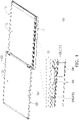
- FIG. 1 is a schematic view of a portable electronic device according to an embodiment of the disclosure.
- FIG. 2 is a schematic cross-sectional view of the portable electronic device of FIG. 1 .
- a portable electronic device 100 may be a laptop, a dual-screen laptop or other foldable electronic devices, and may be rotated 360 degrees.
- the portable electronic device 100 includes a first body 110 and a second body 120 pivoted to the first body 110, the first body 110 has the ability to perform logic operations and data access, and the second body 120 has the ability to display images.
- the second body 120 may be rotated 360 degrees relative to the first body 110. Under the status shown in FIGS. 1 and 2 , the spread angle of the second body 120 relative to the first body 110 is roughly equal to 180 degrees.
- the first body 110 has an operation surface 111 (that is, the surface where the keyboard is located), a bottom surface 112 opposite to the operation surface 111, and an opening 113 located at the bottom surface 112, and the opening 113 serves as a communication path between the external space and the internal space of the first body 110.
- the second body 120 has a display surface 121, a rear surface 122 opposite to the display surface 121, and a magnetic part 123 located at the rear surface 122, and the opening 113 roughly falls on the remote end of the rotation path of the magnetic part 123.
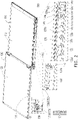
- FIG. 3 is a schematic cross-sectional view of a switch knob of FIG. 2 after the switch knob is unlocked.
- FIG. 4 is a schematic cross-sectional view of a second body in FIG. 3 after the second body is rotated 360 degrees.
- FIG. 5 is a schematic cross-sectional view of a supporting mechanism of FIG. 4 lifting and supporting the second body.
- the portable electronic device 100 further includes a supporting mechanism 130 and a switch knob 140, and the supporting mechanism 130 is disposed in the first body 110 corresponding to the opening 113, and is adapted for moving out of the first body 110 or back into the first body 110 via the opening 113.
- the switch knob 140 is slidably disposed on a side of the first body 110 corresponding to the supporting mechanism 130. Under the status shown in FIG. 2 , the switch knob 140 is engaged with the supporting mechanism 130 to lock the supporting mechanism 130, so that the supporting mechanism 130 may not be lifted. Under the status shown in FIG. 3 , the switch knob 140 is detached from the supporting mechanism 130 to unlock the supporting mechanism 130, so that the supporting mechanism 130 may be driven by the second body 120 to be lifted. As shown in FIGS. 4 and 5 , once the second body 120 stops being rotated and the supporting mechanism 130 is locked, the supporting mechanism 130 supports the second body 120 so that a user may view or operate the display surface 121 of the second body 120.
- the display surface 121 of the second body 120 may be a touch display surface. Since the second body 120 is supported by the supporting mechanism 130, when the user's finger or stylus touches the display surface 121, the second body 120 is unlikely to shake or tilt, thereby having good operating convenience and stability. As shown in FIG. 2 , the supporting mechanism 130 is integrated with a multi-stage positioning design. In the process of lifting the supporting mechanism 130, the supporting mechanism 130 may be selectively locked to a first positioning point, a second positioning point or other positioning points to flexibly adjust the viewing or operating angle of the second body 120.
- the lifting mechanism of the supporting mechanism 130 is explained as follows. Referring to FIGS. 3 and 4 , the second body 120 is first rotated along a first rotating direction R1, so that the rear surface 122 of the second body 120 is rotated toward the bottom surface 112 of the first body 110. When the rear surface 122 of the second body 120 is close to the bottom surface 112 of the first body 110, the spread angle of the second body 120 relative to the first body 110 is roughly equal to 360 degrees, the magnetic part 123 is close to the supporting mechanism 130, and the supporting mechanism 130 is magnetically attracted to the second body 120 through the magnetic attraction of the magnetic part 123.
- the second body 120 is rotated along a second rotating direction R2 opposite to the first rotating direction R1, so that the rear surface 122 of the second body 120 is rotated away from the bottom surface 112 of the first body 110.
- the supporting mechanism 130 is driven by the second body 120 to move out of the first body 110 via the opening 113; that is, the supporting mechanism 130 is driven by the second body 120 to be lifted. For example, once the second body 120 stops being rotated and the supporting mechanism 130 is locked at the first positioning point, the supporting mechanism 130 supports the second body 120.
- FIGS. 6 and 7 are schematic cross-sectional views of the supporting mechanism of FIG. 5 continuously being lifted and supporting the second body.
- the user may continue to rotate the second body 120 along the second rotating direction R2 to unlock the supporting mechanism 130 (that is, to move the supporting mechanism 130 away from the first positioning point), and continue to lift the supporting mechanism 130.
- the supporting mechanism 130 supports the second body 120 to flexibly adjust the viewing angle or operating angle of the second body 120.
- the user only needs to rotate the second body 120 to bring the rear surface 122 thereof close to the bottom surface 112 of the first body 110, and then rotate the rear surface 122 of the second body 120 away from the bottom surface 112 of the first body 110 to allow the second body 120 to drive the supporting mechanism 130 to be lifted.
- the operation is simple and intuitive.
- the supporting mechanism 130 includes a support shaft 131, a magnetic element 132, and a positioning stand 133.
- the support shaft 131 has a first end part 131a and a second end part 131b opposite to the first end part 131a, and the magnetic element 132 is pivoted to the second end part 131b.
- the support shaft 131 and the magnetic element 132 may be lifted and lowered at the same time, and the positioning stand 133 is fixed in the first body 110.
- the magnetic element 132 has a slot disposed corresponding to the switch knob 140, and the switch knob 140 has a latch corresponding to the slot. Under the status shown in FIG.
- the latch of the switch knob 140 is engaged with the slot of the magnetic element 132 to lock the supporting mechanism 130, so that the supporting mechanism 130 may not be lifted.
- the latch of the switch knob 140 is moved away from the slot of the magnetic element 132 to unlock the supporting mechanism 130, so that the supporting mechanism 130 may be driven by the second body 120 to be lifted.
- the positioning stand 133 has a slide rail 133a and a plurality of positioning protrusions 133b.
- the slide rail 133a is aligned with the opening 113, and the positioning protrusions 133b are arranged in the slide rail 133a at intervals.
- the first end part 131a of the support shaft 131 is slidably disposed in the slide rail 133a to slide through any positioning protrusion 133b or be engaged with any positioning protrusion 133b.
- the first end part 131a of the support shaft 131 slides in the slide rail 133a and slides between the positioning protrusions 133b.
- the positioning protrusions 133b are used to provide multi-stage positioning to the support shaft 131 to lock the lifting height or lifting angle of the support shaft 131.
- the lifting height or lifting angle of the support shaft 131 is locked, so that the support shaft 131 stably supports the second body 120.
- the first end part 131a of the support shaft 131 slides in the slide rail 133a along a first direction D1.
- the included angle between the rear surface 122 of the second body 120 and the bottom surface 112 of the first body 110 is A1, as shown in FIG. 5 .
- the included angle between the rear surface 122 of the second body 120 and the bottom surface 112 of the first body 110 is increased to A2, as shown in FIG. 6 .
- the included angle between the rear surface 122 of the second body 120 and the bottom surface 112 of the first body 110 is increased to A3, as shown in FIG. 7 .
- the positioning protrusion 133b structurally interferes with the first end part 131a of the support shaft 131 and prevents the first end part 131a of the support shaft 131 from sliding along a second direction D2 which is opposite to the first direction D1, so as to lock the lifting height or lifting angle of the support shaft 131.
- the lifting height or lifting angle of the support shaft 131 continues to increase, and the included angle between the rear surface 122 of the second body 120 and the bottom surface 112 of the first body 110 continues to increase.
- the first end part 131a of the support shaft 131 may selectively slide along the second direction D2 in the slide rail 133a to reduce the lifting height or lifting angle of the support shaft 131 (that is, the support shaft 131 is lowered) and reduce the included angle between the rear surface 122 of the second body 120 and the bottom surface 112 of the first body 110.
- the supporting mechanism 130 further includes a slider 134.
- the slider 134 is slidably arranged in the slide rail 133a of the positioning stand 133, and slides along the first direction D1 or the second direction D2 with the first end part 131a of the support shaft 131.
- the support shaft 131 further has a projection 131c connected to the first end part 131a, and the projection 131c is slidably connected to the slider 134.
- the slider 134 has a first positioning recess 134a and a second positioning recess 134b connected to the first positioning recess 134a, and the projection 131c slides in the first positioning recess 134a and the second positioning recess 134b.
- the projection 131c slides from the first positioning recess 134a to the second positioning recess 134b, and drives the slider 134 to slide along the first direction D1 in the slide rail 133a.
- the first end part 131a of the support shaft 131 is engaged with any positioning protrusion 133b and is located in the second positioning recess 134b.
- the bottom of the first positioning recess 134a and the top of any positioning protrusion 133b are higher than the bottom of the second positioning recess 134b, and the bottom of the first positioning recess 134a is higher than or as high as the top of any positioning protrusion 133b.
- the projection 131c of the support shaft 131 is located in the first positioning recess 134a, the first end part 131a of the support shaft 131 is detached from any positioning protrusion 133b to prevent the first end part 131a of the support shaft 131 from being blocked by the top of any positioning protrusion 133b and unable to slide.
- the slider 134 further has a first positioning surface 134c and a second positioning surface 134d opposite to the first positioning surface 134c.
- the first positioning surface 134c is connected to the bottom of the first positioning recess 134a
- the second positioning surface 134d is connected to the bottom of the second positioning recess 134b. That is, the first positioning recess 134a and the second positioning recess 134b are located between the first positioning surface 134c and the second positioning surface 134d.
- the positioning stand 133 further has a first guide boss 133c and a second guide boss 133d located in the slide rail 133a, and the positioning protrusions 133b are arranged at intervals between the first guide boss 133c and the second guide boss 133d.
- one of the positioning protrusions 133b is connected to the first guide boss 133c, or one of the positioning protrusions 133b is integrally formed on a side of the first guide boss 133c facing the second guide boss 133d.
- the extension length of the slide rail 133a roughly determines the sliding route of the first end part 131a of the support shaft 131.
- the first guide boss 133c roughly falls on a right dead center position of the sliding route
- the second guide boss 133d roughly falls on a left dead center position of the sliding route.
- the second body 120 is rotated along the second rotating direction R2 and drives the support shaft 131 through the magnetic element 132, so that the first end part 131a of the support shaft 131 slides along the first direction D1 on the first guide boss 133c, and the projection 131c slides from the first positioning recess 134a into the second positioning recess 134b. Since the first end part 131a is supported by the first guide boss 133c, the projection 131c slid into the second positioning recess 134b may not be lowered to the bottom of the second positioning recess 134b for the time being.
- the first end part 131a of the support shaft 131 continues to slide along the first direction D1, so that the projection 131c of the support shaft 131 contacts the second positioning surface 134d and drives the slider 134 to slide along the first direction D1.
- the projection 131c is lowered to the bottom of the second positioning recess 134b.
- the second body 120 continues to be rotated along the second rotating direction R2 and drives the support shaft 131 through the magnetic element 132, so that the first end part 131a of the support shaft 131 continues to slide along the first direction D1.
- the first end part 131a is detached from the first positioning protrusion 133b and slides toward the second positioning protrusion 133b.
- the projection 131c drives the slider 134 to slide toward the second positioning protrusion 133b.
- the first end part 131a and the projection 131c of the support shaft 131 slide through the second positioning protrusion 133b, the first end part 131a and projection 131c are lowered at the same time.
- the support shaft 131 stops sliding the first end part 131a is engaged with the second positioning protrusion 133b, and the projection 131c is lowered to the bottom of the second positioning recess 134b.
- the second body 120 continues to be rotated along the second rotating direction R2 and drives the support shaft 131 through the magnetic element 132, so that the first end part 131a of the support shaft 131 continues to slide along the first direction D1.
- the first end part 131a is detached from the second positioning protrusion 133b and slides toward the third positioning protrusion 133b.
- the projection 131c drives the slider 134 to slide toward the third positioning protrusion 133b.
- the first end part 131a of the support shaft 131 contacts the third positioning protrusion 133b, the first end part 131a and the projection 131c of the support shaft 131 are lifted upwards and slide through the third positioning protrusion 133b.
- the first end part 131a and the projection 131c of the support shaft 131 slide through the third positioning protrusion 133b, the first end part 131a and the projection 131c are lowered at the same time.
- the support shaft 131 stops sliding the first end part 131a is engaged with the third positioning protrusion 133b, and the projection 131c is lowered to the bottom of the second positioning recess 134b.
- FIGS. 8 and 9 are schematic cross-sectional views of the second body of FIG. 7 continuously being lifted.
- the second body 120 continues to be rotated along the second rotating direction R2 and drives the support shaft 131 through the magnetic element 132, so that the first end part 131a of the support shaft 131 continues to slide along the first direction D1.
- the first end part 131a is detached from the third positioning protrusion 133b and slides toward the second guide boss 133d.
- the projection 131c drives the slider 134 to slide toward the second guide boss 133d.
- the magnetic element 132 and the support shaft 131 stop being lifted, and the first end part 131a of the support shaft 131 stops sliding along the first direction D1, so that the second body 120 that continues to be rotated along the second rotating direction R2 is detached from the magnetic element 132.
- the first end part 131a of the support shaft 131 may slide back to the right dead center position along the second direction D2 slide, so that the support shaft 131 and the magnetic element 132 are lowered at the same time and move back into the first body 110 via the opening 113.
- the first end part 131a of the support shaft 131 sliding back to the right dead center position along the second direction D2
- the first end part 131a slides on the second guide boss 133d
- the projection 131c slides from the second positioning recess 134b into the first positioning recess 134a.
- the projection 131c drives the slider 134 to slide along the second direction D2.
- the first end part 131a of the support shaft 131 is not blocked or interfered by the positioning protrusions 133b and thus smoothly slides back to the right dead center position along the second direction D2 and moves back onto the first guide boss 133c.
- the supporting mechanism 130 further includes an auxiliary rod 135 and a torsion spring 136.
- the auxiliary rod 135 has a third end part 135a and a fourth end part 135b opposite to the third end part 135a, and the third end part 135a is pivoted to the first body 110.
- the fourth end part 135b of the auxiliary rod 135 is pivoted to the magnetic element 132 and the second end part 131b of the support shaft 131, and the fourth end part 135b of the auxiliary rod 135, the magnetic element 132, and the second end part 131b of the support shaft 131 are pivoted coaxially.
- the magnetic element 132 is attracted to the rear surface 122 of the second body 120, and the magnetic element 132 driven by the second body 120 drives the support shaft 131 and the auxiliary rod 135 to be lifted at the same time.
- the magnetic element 132, the support shaft 131, and the auxiliary rod 135 may be lifted at the same time and move out of the first body 110 via the opening 113 to jointly support the second body 120.
- two ends of the torsion spring 136 are respectively connected to the third end part 135a of the auxiliary rod 135 and the first body 110.
- the third end part 135a of the auxiliary rod 135 presses against the torsion spring 136, causing elastic deformation of the torsion spring 136.
- the elastic force of the torsion spring 136 acts on the third end part 135a of the auxiliary rod 135, causing the auxiliary rod 135 to be automatically lowered, and at the same time driving the magnetic element 132 and the support shaft 131 to be automatically lowered to move back into the first body 110 via the opening 113, as shown in FIGS. 7 to 9 .
- the elastic force of the torsion spring 136 may indirectly act on the support shaft 131, so that the first end part 131a of the support shaft 131 has a tendency to slide along the second direction D2, so that the first end part 131a of the support shaft 131 is stably engaged with any positioning protrusion 133b.
- the supporting mechanism is not disposed with a torsion spring.
- the user may manually operate the support shaft, the magnetic element, and the auxiliary rod to move the support shaft, the magnetic element, and the auxiliary rod to back into the first body.
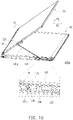
- FIG. 10 is a schematic cross-sectional view of a portable electronic device according to another embodiment of the disclosure.
- a portable electronic device 100A of this embodiment is roughly similar to the portable electronic device 100 shown in FIG. 7 .
- the main difference is: in this embodiment, a supporting mechanism 130a is not disposed with an auxiliary rod nor a torsion spring, but is integrated with an expansion spring 137.
- two ends of the expansion spring 137 are respectively connected to the slider 134 and the first body 110.
- the second body 120 drives the supporting mechanism 130a to be lifted, the slider 134 slides along the first direction D1 and expands the expansion spring 137, causing deformation of the expansion spring 137.
- the expansion spring 137 applies elastic force on the slider 134 to drive the drive slider 134 to slide along the second direction D2, so that the slider 134 drives the support shaft 131 to be automatically lowered and move back into the first body 110 via the opening 113.
- the elastic force of the expansion spring 137 may indirectly act on the support shaft 131, so that the first end part 131a of the support shaft 131 has a tendency to slide along the second direction D2, so that the first end part 131a of the support shaft 131 is stably engaged with any positioning protrusion 133b.
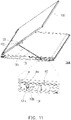
- FIG. 11 is a schematic cross-sectional view of a portable electronic device according to another embodiment of the disclosure.
- a portable electronic device 100B of this embodiment is roughly similar to the portable electronic device 100A shown in FIG. 10 .
- the main difference is: in this embodiment, a supporting mechanism 130b is not disposed with an expansion spring, and the user may manually operate the support shaft 131 and the magnetic element 132 to move the support shaft 131 and the magnetic element 132 back into the first body 110.
- the supporting mechanism may be disposed in the first body and be lifted and lowered.
- the user may rotate the second body along the first rotating direction until a magnetic attraction is generated between the second body and the supporting mechanism and the supporting mechanism is attracted to the second body.
- the second body is rotated along the second rotating direction opposite to the first rotating direction, so that the supporting mechanism is lifted as the second body moves.
- the supporting mechanism supports the second body to prevent the second body from shaking or tilting when being touched by a finger or a stylus, thereby improving convenience and stability in operation.
Landscapes
- Engineering & Computer Science (AREA)
- Computer Hardware Design (AREA)
- Theoretical Computer Science (AREA)
- Physics & Mathematics (AREA)
- General Engineering & Computer Science (AREA)
- Human Computer Interaction (AREA)
- General Physics & Mathematics (AREA)
- Mathematical Physics (AREA)
- Signal Processing (AREA)
- Casings For Electric Apparatus (AREA)
- Telephone Set Structure (AREA)
Abstract
Description
- The disclosure relates to an electronic device, and in particular to a portable electronic device.
- A laptop is formed by a first body and a second body. The first body has the ability to perform logical operations and data access, and the second body has the ability to display images. Through a relative rotation of the first body and the second body, a user may adjust the spread angle of the second body relative to the first body according to personal needs. Take a 360-degree flip laptop as an example. When the spread angle of the second body relative to the first body is greater than or equal to 270 degrees, the first body may be placed flat on the desktop, and the second body may be placed vertically on the desktop for the user to view or operate the second body. Since the second body is unsupported, when the user's finger or stylus touches the second body, the second body shakes or even tilts, causing inconvenience and difficulties in operation for the user.
- The disclosure provides a portable electronic device which provides convenience and stability in operation.
- The disclosure proposes a portable electronic device including a first body, a second body, and a supporting mechanism. The first body has a bottom surface and an opening located at the bottom surface. The second body is pivoted to the first body and has a rear surface and a magnetic part located at the rear surface. The supporting mechanism is disposed in the first body corresponding to the opening. The supporting mechanism includes a support shaft, a magnetic element, and a positioning stand. The support shaft has a first end part and a second end part opposite to the first end part. The positioning stand has a slide rail and multiple positioning protrusions. The positioning protrusions are arranged at intervals in the slide rail. The first end part is slidably disposed in the slide rail. The magnetic element is pivoted to the second end part. The rear surface of the second body is rotated toward the bottom surface of the first body to allow the magnetic element to be magnetically attracted to the magnetic part. Next, the rear surface of the second body is rotated away from the bottom surface of the first body. The magnetic element and the support shaft are driven by the second body to move out from the first body via the opening. When the first end part of the support shaft that slides in the slide rail is engaged with any one of the positioning protrusions, the support shaft supports the second body.
- Based on the above, in the portable electronic device of the disclosure, the supporting mechanism is disposed in the first body and be lifted and lowered. A user rotates the second body along the first rotating direction until a magnetic attraction is generated between the second body and the supporting mechanism and the supporting mechanism is attracted to the second body. Next, the second body is rotated along the second rotating direction opposite to the first rotating direction, so that the supporting mechanism is lifted as the second body moves. Once the second body stops being rotated along the second rotating direction and the supporting mechanism is locked, the supporting mechanism supports the second body to prevent the second body from shaking or tilting when being touched by a finger or a stylus, thereby improving convenience and stability in operation.
- To further describe the above features and advantages of the disclosure, embodiments accompanied with drawings are described below in details.
-
-
FIG. 1 is a schematic view of a portable electronic device according to an embodiment of the disclosure. -
FIG. 2 is a schematic cross-sectional view of the portable electronic device ofFIG. 1 . -
FIG. 3 is a schematic cross-sectional view of a switch knob ofFIG. 2 after the switch knob is unlocked. -
FIG. 4 is a schematic cross-sectional view of a second body inFIG. 3 after the second body is rotated 360 degrees. -
FIG. 5 is a schematic cross-sectional view of a supporting mechanism ofFIG. 4 lifting and supporting the second body. -
FIGS. 6 and7 are schematic cross-sectional views of the supporting mechanism ofFIG. 5 continuously being lifted and supporting the second body. -
FIGS. 8 and9 are schematic cross-sectional views of the second body ofFIG. 7 continuously being lifted. -
FIG. 10 is a schematic cross-sectional view of a portable electronic device according to another embodiment of the disclosure. -
FIG. 11 is a schematic cross-sectional view of a portable electronic device according to another embodiment of the disclosure. -
FIG. 1 is a schematic view of a portable electronic device according to an embodiment of the disclosure.FIG. 2 is a schematic cross-sectional view of the portable electronic device ofFIG. 1 . Referring toFIGS. 1 and2 , in this embodiment, a portableelectronic device 100 may be a laptop, a dual-screen laptop or other foldable electronic devices, and may be rotated 360 degrees. Taking a laptop as an example, the portableelectronic device 100 includes afirst body 110 and asecond body 120 pivoted to thefirst body 110, thefirst body 110 has the ability to perform logic operations and data access, and thesecond body 120 has the ability to display images. In addition, thesecond body 120 may be rotated 360 degrees relative to thefirst body 110. Under the status shown inFIGS. 1 and2 , the spread angle of thesecond body 120 relative to thefirst body 110 is roughly equal to 180 degrees. - The
first body 110 has an operation surface 111 (that is, the surface where the keyboard is located), abottom surface 112 opposite to theoperation surface 111, and anopening 113 located at thebottom surface 112, and theopening 113 serves as a communication path between the external space and the internal space of thefirst body 110. On the other hand, thesecond body 120 has adisplay surface 121, arear surface 122 opposite to thedisplay surface 121, and amagnetic part 123 located at therear surface 122, and theopening 113 roughly falls on the remote end of the rotation path of themagnetic part 123. -
FIG. 3 is a schematic cross-sectional view of a switch knob ofFIG. 2 after the switch knob is unlocked.FIG. 4 is a schematic cross-sectional view of a second body inFIG. 3 after the second body is rotated 360 degrees.FIG. 5 is a schematic cross-sectional view of a supporting mechanism ofFIG. 4 lifting and supporting the second body. Referring toFIGS. 2 to 4 , the portableelectronic device 100 further includes a supportingmechanism 130 and aswitch knob 140, and the supportingmechanism 130 is disposed in thefirst body 110 corresponding to theopening 113, and is adapted for moving out of thefirst body 110 or back into thefirst body 110 via theopening 113. - Specifically, the
switch knob 140 is slidably disposed on a side of thefirst body 110 corresponding to the supportingmechanism 130. Under the status shown inFIG. 2 , theswitch knob 140 is engaged with the supportingmechanism 130 to lock thesupporting mechanism 130, so that the supportingmechanism 130 may not be lifted. Under the status shown inFIG. 3 , theswitch knob 140 is detached from the supportingmechanism 130 to unlock the supportingmechanism 130, so that the supportingmechanism 130 may be driven by thesecond body 120 to be lifted. As shown inFIGS. 4 and5 , once thesecond body 120 stops being rotated and the supportingmechanism 130 is locked, the supportingmechanism 130 supports thesecond body 120 so that a user may view or operate thedisplay surface 121 of thesecond body 120. - As shown in
FIG. 5 , thedisplay surface 121 of thesecond body 120 may be a touch display surface. Since thesecond body 120 is supported by the supportingmechanism 130, when the user's finger or stylus touches thedisplay surface 121, thesecond body 120 is unlikely to shake or tilt, thereby having good operating convenience and stability. As shown inFIG. 2 , the supportingmechanism 130 is integrated with a multi-stage positioning design. In the process of lifting the supportingmechanism 130, the supportingmechanism 130 may be selectively locked to a first positioning point, a second positioning point or other positioning points to flexibly adjust the viewing or operating angle of thesecond body 120. - The lifting mechanism of the supporting
mechanism 130 is explained as follows. Referring toFIGS. 3 and4 , thesecond body 120 is first rotated along a first rotating direction R1, so that therear surface 122 of thesecond body 120 is rotated toward thebottom surface 112 of thefirst body 110. When therear surface 122 of thesecond body 120 is close to thebottom surface 112 of thefirst body 110, the spread angle of thesecond body 120 relative to thefirst body 110 is roughly equal to 360 degrees, themagnetic part 123 is close to the supportingmechanism 130, and the supportingmechanism 130 is magnetically attracted to thesecond body 120 through the magnetic attraction of themagnetic part 123. - Next, referring to
FIGS. 4 and5 , thesecond body 120 is rotated along a second rotating direction R2 opposite to the first rotating direction R1, so that therear surface 122 of thesecond body 120 is rotated away from thebottom surface 112 of thefirst body 110. At the same time, the supportingmechanism 130 is driven by thesecond body 120 to move out of thefirst body 110 via theopening 113; that is, the supportingmechanism 130 is driven by thesecond body 120 to be lifted. For example, once thesecond body 120 stops being rotated and the supportingmechanism 130 is locked at the first positioning point, the supportingmechanism 130 supports thesecond body 120. -
FIGS. 6 and7 are schematic cross-sectional views of the supporting mechanism ofFIG. 5 continuously being lifted and supporting the second body. Referring toFIGS. 5 to 7 , the user may continue to rotate thesecond body 120 along the second rotating direction R2 to unlock the supporting mechanism 130 (that is, to move the supportingmechanism 130 away from the first positioning point), and continue to lift the supportingmechanism 130. Once thesecond body 120 stops being rotated and the supportingmechanism 130 is locked at the second positioning point or other positioning points, the supportingmechanism 130 supports thesecond body 120 to flexibly adjust the viewing angle or operating angle of thesecond body 120. - In other words, the user only needs to rotate the
second body 120 to bring therear surface 122 thereof close to thebottom surface 112 of thefirst body 110, and then rotate therear surface 122 of thesecond body 120 away from thebottom surface 112 of thefirst body 110 to allow thesecond body 120 to drive the supportingmechanism 130 to be lifted. The operation is simple and intuitive. - Referring to
FIGS. 2 and3 , in this embodiment, the supportingmechanism 130 includes asupport shaft 131, amagnetic element 132, and apositioning stand 133. Thesupport shaft 131 has afirst end part 131a and asecond end part 131b opposite to thefirst end part 131a, and themagnetic element 132 is pivoted to thesecond end part 131b. On the other hand, thesupport shaft 131 and themagnetic element 132 may be lifted and lowered at the same time, and thepositioning stand 133 is fixed in thefirst body 110. For example, themagnetic element 132 has a slot disposed corresponding to theswitch knob 140, and theswitch knob 140 has a latch corresponding to the slot. Under the status shown inFIG. 2 , the latch of theswitch knob 140 is engaged with the slot of themagnetic element 132 to lock the supportingmechanism 130, so that the supportingmechanism 130 may not be lifted. Under the status shown inFIG. 3 , the latch of theswitch knob 140 is moved away from the slot of themagnetic element 132 to unlock the supportingmechanism 130, so that the supportingmechanism 130 may be driven by thesecond body 120 to be lifted. - As shown in
FIG. 2 , thepositioning stand 133 has aslide rail 133a and a plurality of positioningprotrusions 133b. Theslide rail 133a is aligned with theopening 113, and the positioningprotrusions 133b are arranged in theslide rail 133a at intervals. As shown inFIGS. 4 to 7 , thefirst end part 131a of thesupport shaft 131 is slidably disposed in theslide rail 133a to slide through anypositioning protrusion 133b or be engaged with anypositioning protrusion 133b. - As shown in
FIGS. 4 to 7 , in the process of lifting thesupport shaft 131 and themagnetic element 132 at the same time, thefirst end part 131a of thesupport shaft 131 slides in theslide rail 133a and slides between the positioningprotrusions 133b. Specifically, the positioningprotrusions 133b are used to provide multi-stage positioning to thesupport shaft 131 to lock the lifting height or lifting angle of thesupport shaft 131. Specifically, when thefirst end part 131a of thesupport shaft 131 is engaged with anypositioning protrusion 133b, the lifting height or lifting angle of thesupport shaft 131 is locked, so that thesupport shaft 131 stably supports thesecond body 120. - In the process of lifting the
support shaft 131, thefirst end part 131a of thesupport shaft 131 slides in theslide rail 133a along a first direction D1. When thefirst end part 131a of thesupport shaft 131 slides along the first direction D1 toward afirst positioning protrusion 133b and is engaged with thefirst positioning protrusion 133b, the included angle between therear surface 122 of thesecond body 120 and thebottom surface 112 of thefirst body 110 is A1, as shown inFIG. 5 . When thefirst end part 131a of thesupport shaft 131 slides along the first direction D1 from thefirst positioning protrusion 133b to asecond positioning protrusion 133b and is engaged with thesecond positioning protrusion 133b, the included angle between therear surface 122 of thesecond body 120 and thebottom surface 112 of thefirst body 110 is increased to A2, as shown inFIG. 6 . When thefirst end part 131a of thesupport shaft 131 slides along the first direction D1 from thesecond positioning protrusion 133b to athird positioning protrusion 133b and is engaged with thethird positioning protrusion 133b, the included angle between therear surface 122 of thesecond body 120 and thebottom surface 112 of thefirst body 110 is increased to A3, as shown inFIG. 7 . - In other words, when the
first end part 131a of thesupport shaft 131 is engaged with anypositioning protrusion 133b, thepositioning protrusion 133b structurally interferes with thefirst end part 131a of thesupport shaft 131 and prevents thefirst end part 131a of thesupport shaft 131 from sliding along a second direction D2 which is opposite to the first direction D1, so as to lock the lifting height or lifting angle of thesupport shaft 131. - Referring to
FIGS. 4 to 7 , in the process of thefirst end part 131a of thesupport shaft 131 sliding along the first direction D1 in theslide rail 133a, the lifting height or lifting angle of thesupport shaft 131 continues to increase, and the included angle between therear surface 122 of thesecond body 120 and thebottom surface 112 of thefirst body 110 continues to increase. In contrast, thefirst end part 131a of thesupport shaft 131 may selectively slide along the second direction D2 in theslide rail 133a to reduce the lifting height or lifting angle of the support shaft 131 (that is, thesupport shaft 131 is lowered) and reduce the included angle between therear surface 122 of thesecond body 120 and thebottom surface 112 of thefirst body 110. - Referring to
FIGS 2 ,4 , and5 , in this embodiment, the supportingmechanism 130 further includes aslider 134. Theslider 134 is slidably arranged in theslide rail 133a of thepositioning stand 133, and slides along the first direction D1 or the second direction D2 with thefirst end part 131a of thesupport shaft 131. Specifically, thesupport shaft 131 further has aprojection 131c connected to thefirst end part 131a, and theprojection 131c is slidably connected to theslider 134. More specifically, theslider 134 has afirst positioning recess 134a and asecond positioning recess 134b connected to thefirst positioning recess 134a, and theprojection 131c slides in thefirst positioning recess 134a and thesecond positioning recess 134b. - Referring to
FIGS. 4 to 7 , in the process of thefirst end part 131a of thesupport shaft 131 sliding along the first direction D1 in theslide rail 133a, theprojection 131c slides from thefirst positioning recess 134a to thesecond positioning recess 134b, and drives theslider 134 to slide along the first direction D1 in theslide rail 133a. When the lifting height or lifting angle of thesupport shaft 131 is locked, thefirst end part 131a of thesupport shaft 131 is engaged with anypositioning protrusion 133b and is located in thesecond positioning recess 134b. - Referring to
FIGS. 2 ,4 , and5 , the bottom of thefirst positioning recess 134a and the top of anypositioning protrusion 133b are higher than the bottom of thesecond positioning recess 134b, and the bottom of thefirst positioning recess 134a is higher than or as high as the top of anypositioning protrusion 133b. When theprojection 131c of thesupport shaft 131 is located in thefirst positioning recess 134a, thefirst end part 131a of thesupport shaft 131 is detached from anypositioning protrusion 133b to prevent thefirst end part 131a of thesupport shaft 131 from being blocked by the top of anypositioning protrusion 133b and unable to slide. - In this embodiment, the
slider 134 further has afirst positioning surface 134c and asecond positioning surface 134d opposite to thefirst positioning surface 134c. Thefirst positioning surface 134c is connected to the bottom of thefirst positioning recess 134a, and thesecond positioning surface 134d is connected to the bottom of thesecond positioning recess 134b. That is, thefirst positioning recess 134a and thesecond positioning recess 134b are located between thefirst positioning surface 134c and thesecond positioning surface 134d. - Specifically, the
positioning stand 133 further has afirst guide boss 133c and asecond guide boss 133d located in theslide rail 133a, and the positioningprotrusions 133b are arranged at intervals between thefirst guide boss 133c and thesecond guide boss 133d. In addition, one of the positioningprotrusions 133b is connected to thefirst guide boss 133c, or one of the positioningprotrusions 133b is integrally formed on a side of thefirst guide boss 133c facing thesecond guide boss 133d. - Referring to
FIGS. 2 and4 , the extension length of theslide rail 133a roughly determines the sliding route of thefirst end part 131a of thesupport shaft 131. Thefirst guide boss 133c roughly falls on a right dead center position of the sliding route, and thesecond guide boss 133d roughly falls on a left dead center position of the sliding route. When thefirst end part 131a of thesupport shaft 131 is at the right dead center position of the sliding route, theprojection 131c is located in thefirst positioning recess 134a of theslider 134, and thefirst end part 131a is located on thefirst guide boss 133c. - As shown in
FIGS. 4 and5 , thesecond body 120 is rotated along the second rotating direction R2 and drives thesupport shaft 131 through themagnetic element 132, so that thefirst end part 131a of thesupport shaft 131 slides along the first direction D1 on thefirst guide boss 133c, and theprojection 131c slides from thefirst positioning recess 134a into thesecond positioning recess 134b. Since thefirst end part 131a is supported by thefirst guide boss 133c, theprojection 131c slid into thesecond positioning recess 134b may not be lowered to the bottom of thesecond positioning recess 134b for the time being. Next, thefirst end part 131a of thesupport shaft 131 continues to slide along the first direction D1, so that theprojection 131c of thesupport shaft 131 contacts thesecond positioning surface 134d and drives theslider 134 to slide along the first direction D1. When thefirst end part 131a of thesupport shaft 131 is detached from thefirst guide boss 133c, theprojection 131c is lowered to the bottom of thesecond positioning recess 134b. Once thesupport shaft 131 stops sliding, thefirst end part 131a is engaged with thefirst positioning protrusion 133b. - As shown in
FIGS. 5 and6 , thesecond body 120 continues to be rotated along the second rotating direction R2 and drives thesupport shaft 131 through themagnetic element 132, so that thefirst end part 131a of thesupport shaft 131 continues to slide along the first direction D1. Thefirst end part 131a is detached from thefirst positioning protrusion 133b and slides toward thesecond positioning protrusion 133b. At the same time, theprojection 131c drives theslider 134 to slide toward thesecond positioning protrusion 133b. When thefirst end part 131a of thesupport shaft 131 contacts thesecond positioning protrusion 133b, thefirst end part 131a and theprojection 131c of thesupport shaft 131 are lifted upwards and slide through thesecond positioning protrusion 133b. After thefirst end part 131a and theprojection 131c of thesupport shaft 131 slide through thesecond positioning protrusion 133b, thefirst end part 131a andprojection 131c are lowered at the same time. Once thesupport shaft 131 stops sliding, thefirst end part 131a is engaged with thesecond positioning protrusion 133b, and theprojection 131c is lowered to the bottom of thesecond positioning recess 134b. - As shown in
FIGS. 6 and7 , thesecond body 120 continues to be rotated along the second rotating direction R2 and drives thesupport shaft 131 through themagnetic element 132, so that thefirst end part 131a of thesupport shaft 131 continues to slide along the first direction D1. Thefirst end part 131a is detached from thesecond positioning protrusion 133b and slides toward thethird positioning protrusion 133b. At the same time, theprojection 131c drives theslider 134 to slide toward thethird positioning protrusion 133b. When thefirst end part 131a of thesupport shaft 131 contacts thethird positioning protrusion 133b, thefirst end part 131a and theprojection 131c of thesupport shaft 131 are lifted upwards and slide through thethird positioning protrusion 133b. After thefirst end part 131a and theprojection 131c of thesupport shaft 131 slide through thethird positioning protrusion 133b, thefirst end part 131a and theprojection 131c are lowered at the same time. Once thesupport shaft 131 stops sliding, thefirst end part 131a is engaged with thethird positioning protrusion 133b, and theprojection 131c is lowered to the bottom of thesecond positioning recess 134b. -
FIGS. 8 and9 are schematic cross-sectional views of the second body ofFIG. 7 continuously being lifted. As shown inFIGS. 7 and8 , thesecond body 120 continues to be rotated along the second rotating direction R2 and drives thesupport shaft 131 through themagnetic element 132, so that thefirst end part 131a of thesupport shaft 131 continues to slide along the first direction D1. Thefirst end part 131a is detached from thethird positioning protrusion 133b and slides toward thesecond guide boss 133d. At the same time, theprojection 131c drives theslider 134 to slide toward thesecond guide boss 133d. When thefirst end part 131a of thesupport shaft 131 contacts thesecond guide boss 133d, thefirst end part 131a and theprojection 131c of thesupport shaft 131 are lifted upwards, and theprojection 131c is detached from the bottom of thesecond positioning recess 134b, and thefirst end part 131a slides on thesecond guide boss 133d. - As shown in
FIGS. 8 and9 , when thefirst end part 131a of thesupport shaft 131 slides to the left dead center position, themagnetic element 132 and thesupport shaft 131 stop being lifted, and thefirst end part 131a of thesupport shaft 131 stops sliding along the first direction D1, so that thesecond body 120 that continues to be rotated along the second rotating direction R2 is detached from themagnetic element 132. Next, thefirst end part 131a of thesupport shaft 131 may slide back to the right dead center position along the second direction D2 slide, so that thesupport shaft 131 and themagnetic element 132 are lowered at the same time and move back into thefirst body 110 via theopening 113. - In the process of the
first end part 131a of thesupport shaft 131 sliding back to the right dead center position along the second direction D2, thefirst end part 131a slides on thesecond guide boss 133d, and theprojection 131c slides from thesecond positioning recess 134b into thefirst positioning recess 134a. After theprojection 131c of thesupport shaft 131 contacts thefirst positioning surface 134c, theprojection 131c drives theslider 134 to slide along the second direction D2. Since theprojection 131c of thesupport shaft 131 is supported by the bottom of thefirst positioning recess 134a, thefirst end part 131a of thesupport shaft 131 is not blocked or interfered by the positioningprotrusions 133b and thus smoothly slides back to the right dead center position along the second direction D2 and moves back onto thefirst guide boss 133c. - Referring to
FIG. 2 , in this embodiment, the supportingmechanism 130 further includes anauxiliary rod 135 and atorsion spring 136. Theauxiliary rod 135 has athird end part 135a and afourth end part 135b opposite to thethird end part 135a, and thethird end part 135a is pivoted to thefirst body 110. In addition, thefourth end part 135b of theauxiliary rod 135 is pivoted to themagnetic element 132 and thesecond end part 131b of thesupport shaft 131, and thefourth end part 135b of theauxiliary rod 135, themagnetic element 132, and thesecond end part 131b of thesupport shaft 131 are pivoted coaxially. - Referring to
FIGS. 5 to 7 , themagnetic element 132 is attracted to therear surface 122 of thesecond body 120, and themagnetic element 132 driven by thesecond body 120 drives thesupport shaft 131 and theauxiliary rod 135 to be lifted at the same time. In other words, themagnetic element 132, thesupport shaft 131, and theauxiliary rod 135 may be lifted at the same time and move out of thefirst body 110 via theopening 113 to jointly support thesecond body 120. In addition, two ends of thetorsion spring 136 are respectively connected to thethird end part 135a of theauxiliary rod 135 and thefirst body 110. In the process of theauxiliary rod 135 being rotated and lifted, thethird end part 135a of theauxiliary rod 135 presses against thetorsion spring 136, causing elastic deformation of thetorsion spring 136. As shown inFIGS. 7 to 9 , when thesecond body 120 continues to be rotated along the second rotating direction R2 and is detached from themagnetic element 132, the elastic force of thetorsion spring 136 acts on thethird end part 135a of theauxiliary rod 135, causing theauxiliary rod 135 to be automatically lowered, and at the same time driving themagnetic element 132 and thesupport shaft 131 to be automatically lowered to move back into thefirst body 110 via theopening 113, as shown inFIGS. 7 to 9 . - As shown in
FIGS. 5 to 7 , the elastic force of thetorsion spring 136 may indirectly act on thesupport shaft 131, so that thefirst end part 131a of thesupport shaft 131 has a tendency to slide along the second direction D2, so that thefirst end part 131a of thesupport shaft 131 is stably engaged with anypositioning protrusion 133b. - In other embodiments, the supporting mechanism is not disposed with a torsion spring. The user may manually operate the support shaft, the magnetic element, and the auxiliary rod to move the support shaft, the magnetic element, and the auxiliary rod to back into the first body.
-
FIG. 10 is a schematic cross-sectional view of a portable electronic device according to another embodiment of the disclosure. Referring toFIG. 10 , a portableelectronic device 100A of this embodiment is roughly similar to the portableelectronic device 100 shown inFIG. 7 . The main difference is: in this embodiment, a supportingmechanism 130a is not disposed with an auxiliary rod nor a torsion spring, but is integrated with anexpansion spring 137. Specifically, two ends of theexpansion spring 137 are respectively connected to theslider 134 and thefirst body 110. When thesecond body 120 drives the supportingmechanism 130a to be lifted, theslider 134 slides along the first direction D1 and expands theexpansion spring 137, causing deformation of theexpansion spring 137. When thesecond body 120 continues to be rotated along the second rotating direction R2 and is detached from themagnetic element 132, theexpansion spring 137 applies elastic force on theslider 134 to drive thedrive slider 134 to slide along the second direction D2, so that theslider 134 drives thesupport shaft 131 to be automatically lowered and move back into thefirst body 110 via theopening 113. - On the other hand, the elastic force of the
expansion spring 137 may indirectly act on thesupport shaft 131, so that thefirst end part 131a of thesupport shaft 131 has a tendency to slide along the second direction D2, so that thefirst end part 131a of thesupport shaft 131 is stably engaged with anypositioning protrusion 133b. -
FIG. 11 is a schematic cross-sectional view of a portable electronic device according to another embodiment of the disclosure. Referring toFIG. 11 , a portableelectronic device 100B of this embodiment is roughly similar to the portableelectronic device 100A shown inFIG. 10 . The main difference is: in this embodiment, a supportingmechanism 130b is not disposed with an expansion spring, and the user may manually operate thesupport shaft 131 and themagnetic element 132 to move thesupport shaft 131 and themagnetic element 132 back into thefirst body 110. - In summary, in the portable electronic device of the disclosure, the supporting mechanism may be disposed in the first body and be lifted and lowered. The user may rotate the second body along the first rotating direction until a magnetic attraction is generated between the second body and the supporting mechanism and the supporting mechanism is attracted to the second body. Next, the second body is rotated along the second rotating direction opposite to the first rotating direction, so that the supporting mechanism is lifted as the second body moves. Once the second body stops being rotated along the second rotating direction and the supporting mechanism is locked, the supporting mechanism supports the second body to prevent the second body from shaking or tilting when being touched by a finger or a stylus, thereby improving convenience and stability in operation.
Claims (13)
- A portable electronic device (100, 100A, 100B), comprising:a first body (110), having a bottom surface (112) and an opening (113) located at the bottom surface (112);a second body (120), pivoted to the first body (110), having a rear surface (122) and a magnetic part (123) located at the rear surface (122); anda supporting mechanism (130, 130a, 130b), disposed in the first body (110) corresponding to the opening (113), wherein the supporting mechanism (130, 130a, 130b) comprises a support shaft (131), a magnetic element (132), and a positioning stand (133), the support shaft (131) has a first end part (131a) and a second end part (131b) opposite to the first end part (131a), the positioning stand (133) has a slide rail (133a) and a plurality of positioning protrusions (133b), the positioning protrusions (133b) are arranged at intervals in the slide rail (133a), the first end part (131a) is slidably disposed in the slide rail (133a), and the magnetic element (132) is pivoted to the second end part (131b), whereinthe rear surface (122) of the second body (120) is rotated toward the bottom surface (112) of the first body (110) to allow the magnetic element (132) to be magnetically attracted to the magnetic part (123), the rear surface (122) of the second body (120) is then rotated away from the bottom surface (112) of the first body (110), the magnetic element (132) and the support shaft (131) are driven by the second body (120) to move out from the first body (110) via the opening (113), and when the first end part (131a) of the support shaft (131) that slides in the slide rail (133a) is engaged with any one of the positioning protrusions (133b), the support shaft (131) supports the second body (120).
- The portable electronic device (100, 100A, 100B) according to claim 1, wherein the first end part (131a) of the support shaft (131) is engaged with one of the positioning protrusions (133b), a first included angle exists between the rear surface (122) of the second body (120) and the bottom surface (112) of the first body (110), the first end part (131a) of the support shaft (131) is engaged with another one of the positioning protrusions (133b), and a second included angle different from the first included angle exists between the rear surface (122) of the second body (120) and the bottom surface (112) of the first body (110).
- The portable electronic device (100, 100A, 100B) according to claim 1 or 2, wherein the supporting mechanism (130, 130a, 130b) further comprises a slider (134), and the slider (134) is slidably disposed in the slide rail (133a) of the positioning stand (133), wherein the support shaft (131) further has a projection (131c) connected to the first end part (131a), and the projection (131c) is slidably connected to the slider (134).
- The portable electronic device (100, 100A, 100B) according to claim 3, wherein the slider (134) has a first positioning recess (134a) and a second positioning recess (134b) connected to the first positioning recess (134a), and the projection (131c) slides in the first positioning recess (134a) and the second positioning recess (134b).
- The portable electronic device (100, 100A, 100B) according to claim 4, wherein the projection (131c) is located in the first positioning recess (134a), and the first end part (131a) is detached from any one of the positioning protrusions (133b).
- The portable electronic device (100, 100A, 100B) according to claim 4 or 5, wherein the first end part (131a) is engaged with any one of the positioning protrusions (133b), and the projection (131c) is located in the second positioning recess (134b).
- The portable electronic device (100, 100A, 100B) according to any of the claims 4 to 6, wherein the slider (134) further has a first positioning surface (134c) and a second positioning surface (134d) opposite to the first positioning surface (134c), the first positioning recess (134a) and the second positioning recess (134b) are located between the first positioning surface (134c) and the second positioning surface (134d), under a status, the projection (131c) is located in the first positioning recess (134a) and contacts the first positioning surface (134c), and under another status, the projection (131c) is located in the second positioning recess (134b) and contacts the second positioning surface (134d).
- The portable electronic device (100, 100A, 100B) according to any of the claims 4 to 7, wherein the positioning stand (133) further has a first guide boss (133c) and a second guide boss (133d) located in the slide rail (133a), the positioning protrusions (133b) are arranged at intervals between the first guide boss (133c) and the second guide boss (133d), one of the positioning protrusions (133b) is connected to the first guide boss (133c), under a status, the projection (131c) is located in the first positioning recess (134a), and the first end part (131a) is located on the first guide boss (133c), and under another status, the projection (131c) is located in the second positioning recess (134b), and the first end part (131a) is located on the second guide boss (133d).
- The portable electronic device (100, 100A, 100B) according to any of the claims 3 to 8, wherein the supporting mechanism (130, 130a, 130b) further comprises an expansion spring (137), and the expansion spring (137) connects the slider (134) and the first body (110).
- The portable electronic device (100, 100A, 100B) according to any of the claims 1 to 8, wherein the supporting mechanism (130, 130a, 130b) further comprises an auxiliary rod (135), the auxiliary rod (135) has a third end part (135a) and a fourth end part (135b) opposite to the third end part (135a), the third end part (135a) is pivoted to the first body (110), and the fourth end part (135b) is pivoted to the magnetic element (132) and the second end part (131b).
- The portable electronic device (100, 100A, 100B) according to claim 10, wherein the support shaft (131), the magnetic element (132), and the auxiliary rod (135) are lifted and lowered at the same time, and move out of the first body (110) or move back into the first body (110) via the opening (113).
- The portable electronic device (100, 100A, 100B) according to claim 10 or 11, wherein the supporting mechanism (130, 130a, 130b) further comprises a torsion spring (136) connecting the first body (110) and the third end part (135a), and as the auxiliary rod (135) is lifted, the torsion spring (136) is pressed against by the third end part (135a) and experiences elastic deformation.
- The portable electronic device (100, 100A, 100B) according to any of the claims 1 to 12, further comprising a switch knob (140) slidably disposed on the first body (110), wherein the switch knob (140) is disposed corresponding to the magnetic element (132) and is engaged with or detached from the magnetic element (132).
Applications Claiming Priority (1)
| Application Number | Priority Date | Filing Date | Title |
|---|---|---|---|
| TW110119905A TWI763514B (en) | 2021-06-01 | 2021-06-01 | Portable electronic device |
Publications (2)
| Publication Number | Publication Date |
|---|---|
| EP4099129A1 true EP4099129A1 (en) | 2022-12-07 |
| EP4099129B1 EP4099129B1 (en) | 2024-03-27 |
Family
ID=80953610
Family Applications (1)
| Application Number | Title | Priority Date | Filing Date |
|---|---|---|---|
| EP22157107.8A Active EP4099129B1 (en) | 2021-06-01 | 2022-02-16 | Portable electronic device |
Country Status (3)
| Country | Link |
|---|---|
| US (1) | US11846999B2 (en) |
| EP (1) | EP4099129B1 (en) |
| TW (1) | TWI763514B (en) |
Families Citing this family (1)
| Publication number | Priority date | Publication date | Assignee | Title |
|---|---|---|---|---|
| TWI746223B (en) * | 2020-10-22 | 2021-11-11 | 宏碁股份有限公司 | Portable electronic device with multiple displays |
Citations (3)
| Publication number | Priority date | Publication date | Assignee | Title |
|---|---|---|---|---|
| US20140160654A1 (en) * | 2012-12-11 | 2014-06-12 | Samsung Electronics Co., Ltd. | Foldable computing apparatus and method of erecting display unit |
| US20170090522A1 (en) * | 2015-09-24 | 2017-03-30 | Compal Electronics, Inc. | Portable electronic device |
| WO2018226209A1 (en) * | 2017-06-06 | 2018-12-13 | Hewlett-Packard Development Company, L.P. | Computing devices with a kickstand |
Family Cites Families (7)
| Publication number | Priority date | Publication date | Assignee | Title |
|---|---|---|---|---|
| TWI528883B (en) * | 2012-08-13 | 2016-04-01 | 緯創資通股份有限公司 | Portable computer |
| CN203350779U (en) * | 2013-06-28 | 2013-12-18 | 纬创资通股份有限公司 | Portable electronic device and support module |
| US10558244B1 (en) * | 2019-01-31 | 2020-02-11 | Dell Products L.P. | Transformative information handling system dual axis stand |
| US10606319B1 (en) * | 2019-01-31 | 2020-03-31 | Dell Products L.P. | Transformative information handling system display height brake |
| US10860068B2 (en) * | 2019-01-31 | 2020-12-08 | Dell Products L.P. | Transformative information handling cable management |
| US10635132B1 (en) * | 2019-01-31 | 2020-04-28 | Dell Products L.P. | Portable information handling system management of transformation between clamshell and all-in-one positions |
| US10585451B1 (en) * | 2019-01-31 | 2020-03-10 | Dell Products L.P. | Transformative portable information handling system adaptive display arrangement |
-
2021
- 2021-06-01 TW TW110119905A patent/TWI763514B/en active
-
2022
- 2022-01-10 US US17/571,548 patent/US11846999B2/en active Active
- 2022-02-16 EP EP22157107.8A patent/EP4099129B1/en active Active
Patent Citations (3)
| Publication number | Priority date | Publication date | Assignee | Title |
|---|---|---|---|---|
| US20140160654A1 (en) * | 2012-12-11 | 2014-06-12 | Samsung Electronics Co., Ltd. | Foldable computing apparatus and method of erecting display unit |
| US20170090522A1 (en) * | 2015-09-24 | 2017-03-30 | Compal Electronics, Inc. | Portable electronic device |
| WO2018226209A1 (en) * | 2017-06-06 | 2018-12-13 | Hewlett-Packard Development Company, L.P. | Computing devices with a kickstand |
Also Published As
| Publication number | Publication date |
|---|---|
| EP4099129B1 (en) | 2024-03-27 |
| US11846999B2 (en) | 2023-12-19 |
| US20220382339A1 (en) | 2022-12-01 |
| TWI763514B (en) | 2022-05-01 |
| TW202248790A (en) | 2022-12-16 |
Similar Documents
| Publication | Publication Date | Title |
|---|---|---|
| US11703909B2 (en) | Electronic apparatus | |
| US5708562A (en) | Portable computer and a keyboard therefor | |
| US7889488B2 (en) | Electronic apparatus having lock unit | |
| EP2044499B1 (en) | Anti-rotation mechanism for an electronic device | |
| US8665589B2 (en) | Peripheral input device | |
| US6850407B2 (en) | Electronic apparatus having two housings coupled by hinge mechanism, one of which is reversible to the other | |
| US20210384670A1 (en) | Socket structure and portable electronic device | |
| CN1316331C (en) | Electronic device | |
| US7963000B2 (en) | Flip apparatus and electronic device using the same | |
| CN113515174B (en) | Dual-screen laptop computer | |
| US20030052856A1 (en) | Mounting a display panel in a computer | |
| US10025348B2 (en) | Electronic device and locking mechanism | |
| US11841743B2 (en) | Electronic device | |
| EP3796126B1 (en) | Hinge module and portable electronic device | |
| CN102082845A (en) | Electronic device | |
| EP4099129B1 (en) | Portable electronic device | |
| WO2018226209A1 (en) | Computing devices with a kickstand | |
| CN115454205A (en) | Portable electronic device | |
| US20230221772A1 (en) | Electronic device | |
| CN101652046A (en) | Electronic device | |
| TWI799291B (en) | Portable electronic deivce | |
| CN212411105U (en) | electronic device | |
| EP3467613A1 (en) | Engaging mechanism, transmission dock equipped with the same, and electronic apparatus having the same | |
| TWI736323B (en) | Electronic device | |
| TWM643012U (en) | Input device and electronic apparatus |
Legal Events
| Date | Code | Title | Description |
|---|---|---|---|
| PUAI | Public reference made under article 153(3) epc to a published international application that has entered the european phase |
Free format text: ORIGINAL CODE: 0009012 |
|
| STAA | Information on the status of an ep patent application or granted ep patent |
Free format text: STATUS: THE APPLICATION HAS BEEN PUBLISHED |
|
| AK | Designated contracting states |
Kind code of ref document: A1 Designated state(s): AL AT BE BG CH CY CZ DE DK EE ES FI FR GB GR HR HU IE IS IT LI LT LU LV MC MK MT NL NO PL PT RO RS SE SI SK SM TR |
|
| STAA | Information on the status of an ep patent application or granted ep patent |
Free format text: STATUS: REQUEST FOR EXAMINATION WAS MADE |
|
| 17P | Request for examination filed |
Effective date: 20230607 |
|
| RBV | Designated contracting states (corrected) |
Designated state(s): AL AT BE BG CH CY CZ DE DK EE ES FI FR GB GR HR HU IE IS IT LI LT LU LV MC MK MT NL NO PL PT RO RS SE SI SK SM TR |
|
| GRAP | Despatch of communication of intention to grant a patent |
Free format text: ORIGINAL CODE: EPIDOSNIGR1 |
|
| STAA | Information on the status of an ep patent application or granted ep patent |
Free format text: STATUS: GRANT OF PATENT IS INTENDED |
|
| INTG | Intention to grant announced |
Effective date: 20231109 |
|
| GRAS | Grant fee paid |
Free format text: ORIGINAL CODE: EPIDOSNIGR3 |
|
| GRAA | (expected) grant |
Free format text: ORIGINAL CODE: 0009210 |
|
| STAA | Information on the status of an ep patent application or granted ep patent |
Free format text: STATUS: THE PATENT HAS BEEN GRANTED |
|
| AK | Designated contracting states |
Kind code of ref document: B1 Designated state(s): AL AT BE BG CH CY CZ DE DK EE ES FI FR GB GR HR HU IE IS IT LI LT LU LV MC MK MT NL NO PL PT RO RS SE SI SK SM TR |
|
| REG | Reference to a national code |
Ref country code: GB Ref legal event code: FG4D |
|
| REG | Reference to a national code |
Ref country code: CH Ref legal event code: EP |
|
| REG | Reference to a national code |
Ref country code: DE Ref legal event code: R096 Ref document number: 602022002492 Country of ref document: DE |
|
| REG | Reference to a national code |
Ref country code: IE Ref legal event code: FG4D |
|
| PG25 | Lapsed in a contracting state [announced via postgrant information from national office to epo] |
Ref country code: LT Free format text: LAPSE BECAUSE OF FAILURE TO SUBMIT A TRANSLATION OF THE DESCRIPTION OR TO PAY THE FEE WITHIN THE PRESCRIBED TIME-LIMIT Effective date: 20240327 |
|
| REG | Reference to a national code |
Ref country code: LT Ref legal event code: MG9D |
|
| PG25 | Lapsed in a contracting state [announced via postgrant information from national office to epo] |
Ref country code: GR Free format text: LAPSE BECAUSE OF FAILURE TO SUBMIT A TRANSLATION OF THE DESCRIPTION OR TO PAY THE FEE WITHIN THE PRESCRIBED TIME-LIMIT Effective date: 20240628 |
|
| PG25 | Lapsed in a contracting state [announced via postgrant information from national office to epo] |
Ref country code: HR Free format text: LAPSE BECAUSE OF FAILURE TO SUBMIT A TRANSLATION OF THE DESCRIPTION OR TO PAY THE FEE WITHIN THE PRESCRIBED TIME-LIMIT Effective date: 20240327 Ref country code: RS Free format text: LAPSE BECAUSE OF FAILURE TO SUBMIT A TRANSLATION OF THE DESCRIPTION OR TO PAY THE FEE WITHIN THE PRESCRIBED TIME-LIMIT Effective date: 20240627 |
|
| PG25 | Lapsed in a contracting state [announced via postgrant information from national office to epo] |
Ref country code: RS Free format text: LAPSE BECAUSE OF FAILURE TO SUBMIT A TRANSLATION OF THE DESCRIPTION OR TO PAY THE FEE WITHIN THE PRESCRIBED TIME-LIMIT Effective date: 20240627 Ref country code: NO Free format text: LAPSE BECAUSE OF FAILURE TO SUBMIT A TRANSLATION OF THE DESCRIPTION OR TO PAY THE FEE WITHIN THE PRESCRIBED TIME-LIMIT Effective date: 20240627 Ref country code: LT Free format text: LAPSE BECAUSE OF FAILURE TO SUBMIT A TRANSLATION OF THE DESCRIPTION OR TO PAY THE FEE WITHIN THE PRESCRIBED TIME-LIMIT Effective date: 20240327 Ref country code: HR Free format text: LAPSE BECAUSE OF FAILURE TO SUBMIT A TRANSLATION OF THE DESCRIPTION OR TO PAY THE FEE WITHIN THE PRESCRIBED TIME-LIMIT Effective date: 20240327 Ref country code: GR Free format text: LAPSE BECAUSE OF FAILURE TO SUBMIT A TRANSLATION OF THE DESCRIPTION OR TO PAY THE FEE WITHIN THE PRESCRIBED TIME-LIMIT Effective date: 20240628 Ref country code: FI Free format text: LAPSE BECAUSE OF FAILURE TO SUBMIT A TRANSLATION OF THE DESCRIPTION OR TO PAY THE FEE WITHIN THE PRESCRIBED TIME-LIMIT Effective date: 20240327 Ref country code: BG Free format text: LAPSE BECAUSE OF FAILURE TO SUBMIT A TRANSLATION OF THE DESCRIPTION OR TO PAY THE FEE WITHIN THE PRESCRIBED TIME-LIMIT Effective date: 20240327 |
|
| REG | Reference to a national code |
Ref country code: NL Ref legal event code: MP Effective date: 20240327 |
|
| PG25 | Lapsed in a contracting state [announced via postgrant information from national office to epo] |
Ref country code: SE Free format text: LAPSE BECAUSE OF FAILURE TO SUBMIT A TRANSLATION OF THE DESCRIPTION OR TO PAY THE FEE WITHIN THE PRESCRIBED TIME-LIMIT Effective date: 20240327 Ref country code: LV Free format text: LAPSE BECAUSE OF FAILURE TO SUBMIT A TRANSLATION OF THE DESCRIPTION OR TO PAY THE FEE WITHIN THE PRESCRIBED TIME-LIMIT Effective date: 20240327 |
|
| PG25 | Lapsed in a contracting state [announced via postgrant information from national office to epo] |
Ref country code: NL Free format text: LAPSE BECAUSE OF FAILURE TO SUBMIT A TRANSLATION OF THE DESCRIPTION OR TO PAY THE FEE WITHIN THE PRESCRIBED TIME-LIMIT Effective date: 20240327 |
|
| REG | Reference to a national code |
Ref country code: AT Ref legal event code: MK05 Ref document number: 1670520 Country of ref document: AT Kind code of ref document: T Effective date: 20240327 |
|
| PG25 | Lapsed in a contracting state [announced via postgrant information from national office to epo] |
Ref country code: NL Free format text: LAPSE BECAUSE OF FAILURE TO SUBMIT A TRANSLATION OF THE DESCRIPTION OR TO PAY THE FEE WITHIN THE PRESCRIBED TIME-LIMIT Effective date: 20240327 |
|
| PG25 | Lapsed in a contracting state [announced via postgrant information from national office to epo] |
Ref country code: IS Free format text: LAPSE BECAUSE OF FAILURE TO SUBMIT A TRANSLATION OF THE DESCRIPTION OR TO PAY THE FEE WITHIN THE PRESCRIBED TIME-LIMIT Effective date: 20240727 |
|
| PG25 | Lapsed in a contracting state [announced via postgrant information from national office to epo] |
Ref country code: PT Free format text: LAPSE BECAUSE OF FAILURE TO SUBMIT A TRANSLATION OF THE DESCRIPTION OR TO PAY THE FEE WITHIN THE PRESCRIBED TIME-LIMIT Effective date: 20240729 Ref country code: SM Free format text: LAPSE BECAUSE OF FAILURE TO SUBMIT A TRANSLATION OF THE DESCRIPTION OR TO PAY THE FEE WITHIN THE PRESCRIBED TIME-LIMIT Effective date: 20240327 |
|
| PG25 | Lapsed in a contracting state [announced via postgrant information from national office to epo] |
Ref country code: ES Free format text: LAPSE BECAUSE OF FAILURE TO SUBMIT A TRANSLATION OF THE DESCRIPTION OR TO PAY THE FEE WITHIN THE PRESCRIBED TIME-LIMIT Effective date: 20240327 |
|
| PG25 | Lapsed in a contracting state [announced via postgrant information from national office to epo] |
Ref country code: EE Free format text: LAPSE BECAUSE OF FAILURE TO SUBMIT A TRANSLATION OF THE DESCRIPTION OR TO PAY THE FEE WITHIN THE PRESCRIBED TIME-LIMIT Effective date: 20240327 Ref country code: CZ Free format text: LAPSE BECAUSE OF FAILURE TO SUBMIT A TRANSLATION OF THE DESCRIPTION OR TO PAY THE FEE WITHIN THE PRESCRIBED TIME-LIMIT Effective date: 20240327 |
|
| PG25 | Lapsed in a contracting state [announced via postgrant information from national office to epo] |
Ref country code: AT Free format text: LAPSE BECAUSE OF FAILURE TO SUBMIT A TRANSLATION OF THE DESCRIPTION OR TO PAY THE FEE WITHIN THE PRESCRIBED TIME-LIMIT Effective date: 20240327 |
|
| PG25 | Lapsed in a contracting state [announced via postgrant information from national office to epo] |
Ref country code: PL Free format text: LAPSE BECAUSE OF FAILURE TO SUBMIT A TRANSLATION OF THE DESCRIPTION OR TO PAY THE FEE WITHIN THE PRESCRIBED TIME-LIMIT Effective date: 20240327 |
|
| PG25 | Lapsed in a contracting state [announced via postgrant information from national office to epo] |
Ref country code: SK Free format text: LAPSE BECAUSE OF FAILURE TO SUBMIT A TRANSLATION OF THE DESCRIPTION OR TO PAY THE FEE WITHIN THE PRESCRIBED TIME-LIMIT Effective date: 20240327 |
|
| PG25 | Lapsed in a contracting state [announced via postgrant information from national office to epo] |
Ref country code: SM Free format text: LAPSE BECAUSE OF FAILURE TO SUBMIT A TRANSLATION OF THE DESCRIPTION OR TO PAY THE FEE WITHIN THE PRESCRIBED TIME-LIMIT Effective date: 20240327 Ref country code: SK Free format text: LAPSE BECAUSE OF FAILURE TO SUBMIT A TRANSLATION OF THE DESCRIPTION OR TO PAY THE FEE WITHIN THE PRESCRIBED TIME-LIMIT Effective date: 20240327 Ref country code: RO Free format text: LAPSE BECAUSE OF FAILURE TO SUBMIT A TRANSLATION OF THE DESCRIPTION OR TO PAY THE FEE WITHIN THE PRESCRIBED TIME-LIMIT Effective date: 20240327 Ref country code: PT Free format text: LAPSE BECAUSE OF FAILURE TO SUBMIT A TRANSLATION OF THE DESCRIPTION OR TO PAY THE FEE WITHIN THE PRESCRIBED TIME-LIMIT Effective date: 20240729 Ref country code: PL Free format text: LAPSE BECAUSE OF FAILURE TO SUBMIT A TRANSLATION OF THE DESCRIPTION OR TO PAY THE FEE WITHIN THE PRESCRIBED TIME-LIMIT Effective date: 20240327 Ref country code: IS Free format text: LAPSE BECAUSE OF FAILURE TO SUBMIT A TRANSLATION OF THE DESCRIPTION OR TO PAY THE FEE WITHIN THE PRESCRIBED TIME-LIMIT Effective date: 20240727 Ref country code: ES Free format text: LAPSE BECAUSE OF FAILURE TO SUBMIT A TRANSLATION OF THE DESCRIPTION OR TO PAY THE FEE WITHIN THE PRESCRIBED TIME-LIMIT Effective date: 20240327 Ref country code: EE Free format text: LAPSE BECAUSE OF FAILURE TO SUBMIT A TRANSLATION OF THE DESCRIPTION OR TO PAY THE FEE WITHIN THE PRESCRIBED TIME-LIMIT Effective date: 20240327 Ref country code: CZ Free format text: LAPSE BECAUSE OF FAILURE TO SUBMIT A TRANSLATION OF THE DESCRIPTION OR TO PAY THE FEE WITHIN THE PRESCRIBED TIME-LIMIT Effective date: 20240327 Ref country code: AT Free format text: LAPSE BECAUSE OF FAILURE TO SUBMIT A TRANSLATION OF THE DESCRIPTION OR TO PAY THE FEE WITHIN THE PRESCRIBED TIME-LIMIT Effective date: 20240327 |
|
| PG25 | Lapsed in a contracting state [announced via postgrant information from national office to epo] |
Ref country code: IT Free format text: LAPSE BECAUSE OF FAILURE TO SUBMIT A TRANSLATION OF THE DESCRIPTION OR TO PAY THE FEE WITHIN THE PRESCRIBED TIME-LIMIT Effective date: 20240327 |
|
| PG25 | Lapsed in a contracting state [announced via postgrant information from national office to epo] |
Ref country code: IT Free format text: LAPSE BECAUSE OF FAILURE TO SUBMIT A TRANSLATION OF THE DESCRIPTION OR TO PAY THE FEE WITHIN THE PRESCRIBED TIME-LIMIT Effective date: 20240327 |
|
| REG | Reference to a national code |
Ref country code: DE Ref legal event code: R097 Ref document number: 602022002492 Country of ref document: DE |
|
| PG25 | Lapsed in a contracting state [announced via postgrant information from national office to epo] |
Ref country code: DK Free format text: LAPSE BECAUSE OF FAILURE TO SUBMIT A TRANSLATION OF THE DESCRIPTION OR TO PAY THE FEE WITHIN THE PRESCRIBED TIME-LIMIT Effective date: 20240327 |
|
| PG25 | Lapsed in a contracting state [announced via postgrant information from national office to epo] |
Ref country code: DK Free format text: LAPSE BECAUSE OF FAILURE TO SUBMIT A TRANSLATION OF THE DESCRIPTION OR TO PAY THE FEE WITHIN THE PRESCRIBED TIME-LIMIT Effective date: 20240327 |
|
| PLBE | No opposition filed within time limit |
Free format text: ORIGINAL CODE: 0009261 |
|
| STAA | Information on the status of an ep patent application or granted ep patent |
Free format text: STATUS: NO OPPOSITION FILED WITHIN TIME LIMIT |
|
| 26N | No opposition filed |
Effective date: 20250103 |
|
| PG25 | Lapsed in a contracting state [announced via postgrant information from national office to epo] |
Ref country code: SI Free format text: LAPSE BECAUSE OF FAILURE TO SUBMIT A TRANSLATION OF THE DESCRIPTION OR TO PAY THE FEE WITHIN THE PRESCRIBED TIME-LIMIT Effective date: 20240327 |
|
| PG25 | Lapsed in a contracting state [announced via postgrant information from national office to epo] |
Ref country code: MC Free format text: LAPSE BECAUSE OF FAILURE TO SUBMIT A TRANSLATION OF THE DESCRIPTION OR TO PAY THE FEE WITHIN THE PRESCRIBED TIME-LIMIT Effective date: 20240327 |
|
| REG | Reference to a national code |
Ref country code: CH Ref legal event code: PL |
|
| PG25 | Lapsed in a contracting state [announced via postgrant information from national office to epo] |
Ref country code: LU Free format text: LAPSE BECAUSE OF NON-PAYMENT OF DUE FEES Effective date: 20250216 |
|
| PG25 | Lapsed in a contracting state [announced via postgrant information from national office to epo] |
Ref country code: CH Free format text: LAPSE BECAUSE OF NON-PAYMENT OF DUE FEES Effective date: 20250228 |
|
| REG | Reference to a national code |
Ref country code: BE Ref legal event code: MM Effective date: 20250228 |
|
| PG25 | Lapsed in a contracting state [announced via postgrant information from national office to epo] |
Ref country code: BE Free format text: LAPSE BECAUSE OF NON-PAYMENT OF DUE FEES Effective date: 20250228 |
|
| PG25 | Lapsed in a contracting state [announced via postgrant information from national office to epo] |
Ref country code: IE Free format text: LAPSE BECAUSE OF NON-PAYMENT OF DUE FEES Effective date: 20250216 |
|
| PGFP | Annual fee paid to national office [announced via postgrant information from national office to epo] |
Ref country code: GB Payment date: 20260112 Year of fee payment: 5 |
|
| PGFP | Annual fee paid to national office [announced via postgrant information from national office to epo] |
Ref country code: DE Payment date: 20260107 Year of fee payment: 5 |
|
| PGFP | Annual fee paid to national office [announced via postgrant information from national office to epo] |
Ref country code: FR Payment date: 20260108 Year of fee payment: 5 |
|
| PG25 | Lapsed in a contracting state [announced via postgrant information from national office to epo] |
Ref country code: CY Free format text: LAPSE BECAUSE OF FAILURE TO SUBMIT A TRANSLATION OF THE DESCRIPTION OR TO PAY THE FEE WITHIN THE PRESCRIBED TIME-LIMIT Effective date: 20240327 |
|
| PG25 | Lapsed in a contracting state [announced via postgrant information from national office to epo] |
Ref country code: TR Free format text: LAPSE BECAUSE OF FAILURE TO SUBMIT A TRANSLATION OF THE DESCRIPTION OR TO PAY THE FEE WITHIN THE PRESCRIBED TIME-LIMIT Effective date: 20240327 |