EP4098959B1 - Refrigerator - Google Patents
Refrigerator Download PDFInfo
- Publication number
- EP4098959B1 EP4098959B1 EP22186892.0A EP22186892A EP4098959B1 EP 4098959 B1 EP4098959 B1 EP 4098959B1 EP 22186892 A EP22186892 A EP 22186892A EP 4098959 B1 EP4098959 B1 EP 4098959B1
- Authority
- EP
- European Patent Office
- Prior art keywords
- duct
- freezing chamber
- refrigerating chamber
- chamber
- refrigerator
- Prior art date
- Legal status (The legal status is an assumption and is not a legal conclusion. Google has not performed a legal analysis and makes no representation as to the accuracy of the status listed.)
- Active
Links
Images




Classifications
-
- F—MECHANICAL ENGINEERING; LIGHTING; HEATING; WEAPONS; BLASTING
- F25—REFRIGERATION OR COOLING; COMBINED HEATING AND REFRIGERATION SYSTEMS; HEAT PUMP SYSTEMS; MANUFACTURE OR STORAGE OF ICE; LIQUEFACTION SOLIDIFICATION OF GASES
- F25D—REFRIGERATORS; COLD ROOMS; ICE-BOXES; COOLING OR FREEZING APPARATUS NOT OTHERWISE PROVIDED FOR
- F25D17/00—Arrangements for circulating cooling fluids; Arrangements for circulating gas, e.g. air, within refrigerated spaces
- F25D17/04—Arrangements for circulating cooling fluids; Arrangements for circulating gas, e.g. air, within refrigerated spaces for circulating air, e.g. by convection
- F25D17/042—Air treating means within refrigerated spaces
- F25D17/045—Air flow control arrangements
-
- F—MECHANICAL ENGINEERING; LIGHTING; HEATING; WEAPONS; BLASTING
- F25—REFRIGERATION OR COOLING; COMBINED HEATING AND REFRIGERATION SYSTEMS; HEAT PUMP SYSTEMS; MANUFACTURE OR STORAGE OF ICE; LIQUEFACTION SOLIDIFICATION OF GASES
- F25D—REFRIGERATORS; COLD ROOMS; ICE-BOXES; COOLING OR FREEZING APPARATUS NOT OTHERWISE PROVIDED FOR
- F25D11/00—Self-contained movable devices, e.g. domestic refrigerators
- F25D11/02—Self-contained movable devices, e.g. domestic refrigerators with cooling compartments at different temperatures
-
- F—MECHANICAL ENGINEERING; LIGHTING; HEATING; WEAPONS; BLASTING
- F25—REFRIGERATION OR COOLING; COMBINED HEATING AND REFRIGERATION SYSTEMS; HEAT PUMP SYSTEMS; MANUFACTURE OR STORAGE OF ICE; LIQUEFACTION SOLIDIFICATION OF GASES
- F25D—REFRIGERATORS; COLD ROOMS; ICE-BOXES; COOLING OR FREEZING APPARATUS NOT OTHERWISE PROVIDED FOR
- F25D17/00—Arrangements for circulating cooling fluids; Arrangements for circulating gas, e.g. air, within refrigerated spaces
- F25D17/04—Arrangements for circulating cooling fluids; Arrangements for circulating gas, e.g. air, within refrigerated spaces for circulating air, e.g. by convection
- F25D17/06—Arrangements for circulating cooling fluids; Arrangements for circulating gas, e.g. air, within refrigerated spaces for circulating air, e.g. by convection by forced circulation
- F25D17/062—Arrangements for circulating cooling fluids; Arrangements for circulating gas, e.g. air, within refrigerated spaces for circulating air, e.g. by convection by forced circulation in household refrigerators
-
- F—MECHANICAL ENGINEERING; LIGHTING; HEATING; WEAPONS; BLASTING
- F25—REFRIGERATION OR COOLING; COMBINED HEATING AND REFRIGERATION SYSTEMS; HEAT PUMP SYSTEMS; MANUFACTURE OR STORAGE OF ICE; LIQUEFACTION SOLIDIFICATION OF GASES
- F25D—REFRIGERATORS; COLD ROOMS; ICE-BOXES; COOLING OR FREEZING APPARATUS NOT OTHERWISE PROVIDED FOR
- F25D17/00—Arrangements for circulating cooling fluids; Arrangements for circulating gas, e.g. air, within refrigerated spaces
- F25D17/04—Arrangements for circulating cooling fluids; Arrangements for circulating gas, e.g. air, within refrigerated spaces for circulating air, e.g. by convection
- F25D17/06—Arrangements for circulating cooling fluids; Arrangements for circulating gas, e.g. air, within refrigerated spaces for circulating air, e.g. by convection by forced circulation
- F25D17/062—Arrangements for circulating cooling fluids; Arrangements for circulating gas, e.g. air, within refrigerated spaces for circulating air, e.g. by convection by forced circulation in household refrigerators
- F25D17/065—Arrangements for circulating cooling fluids; Arrangements for circulating gas, e.g. air, within refrigerated spaces for circulating air, e.g. by convection by forced circulation in household refrigerators with compartments at different temperatures
-
- F—MECHANICAL ENGINEERING; LIGHTING; HEATING; WEAPONS; BLASTING
- F25—REFRIGERATION OR COOLING; COMBINED HEATING AND REFRIGERATION SYSTEMS; HEAT PUMP SYSTEMS; MANUFACTURE OR STORAGE OF ICE; LIQUEFACTION SOLIDIFICATION OF GASES
- F25D—REFRIGERATORS; COLD ROOMS; ICE-BOXES; COOLING OR FREEZING APPARATUS NOT OTHERWISE PROVIDED FOR
- F25D17/00—Arrangements for circulating cooling fluids; Arrangements for circulating gas, e.g. air, within refrigerated spaces
- F25D17/04—Arrangements for circulating cooling fluids; Arrangements for circulating gas, e.g. air, within refrigerated spaces for circulating air, e.g. by convection
- F25D17/06—Arrangements for circulating cooling fluids; Arrangements for circulating gas, e.g. air, within refrigerated spaces for circulating air, e.g. by convection by forced circulation
- F25D17/08—Arrangements for circulating cooling fluids; Arrangements for circulating gas, e.g. air, within refrigerated spaces for circulating air, e.g. by convection by forced circulation using ducts
-
- F—MECHANICAL ENGINEERING; LIGHTING; HEATING; WEAPONS; BLASTING
- F25—REFRIGERATION OR COOLING; COMBINED HEATING AND REFRIGERATION SYSTEMS; HEAT PUMP SYSTEMS; MANUFACTURE OR STORAGE OF ICE; LIQUEFACTION SOLIDIFICATION OF GASES
- F25D—REFRIGERATORS; COLD ROOMS; ICE-BOXES; COOLING OR FREEZING APPARATUS NOT OTHERWISE PROVIDED FOR
- F25D21/00—Defrosting; Preventing frosting; Removing condensed or defrost water
- F25D21/04—Preventing the formation of frost or condensate
-
- F—MECHANICAL ENGINEERING; LIGHTING; HEATING; WEAPONS; BLASTING
- F25—REFRIGERATION OR COOLING; COMBINED HEATING AND REFRIGERATION SYSTEMS; HEAT PUMP SYSTEMS; MANUFACTURE OR STORAGE OF ICE; LIQUEFACTION SOLIDIFICATION OF GASES
- F25D—REFRIGERATORS; COLD ROOMS; ICE-BOXES; COOLING OR FREEZING APPARATUS NOT OTHERWISE PROVIDED FOR
- F25D21/00—Defrosting; Preventing frosting; Removing condensed or defrost water
- F25D21/06—Removing frost
- F25D21/08—Removing frost by electric heating
-
- F—MECHANICAL ENGINEERING; LIGHTING; HEATING; WEAPONS; BLASTING
- F25—REFRIGERATION OR COOLING; COMBINED HEATING AND REFRIGERATION SYSTEMS; HEAT PUMP SYSTEMS; MANUFACTURE OR STORAGE OF ICE; LIQUEFACTION SOLIDIFICATION OF GASES
- F25D—REFRIGERATORS; COLD ROOMS; ICE-BOXES; COOLING OR FREEZING APPARATUS NOT OTHERWISE PROVIDED FOR
- F25D21/00—Defrosting; Preventing frosting; Removing condensed or defrost water
- F25D21/14—Collecting or removing condensed and defrost water; Drip trays
-
- F—MECHANICAL ENGINEERING; LIGHTING; HEATING; WEAPONS; BLASTING
- F25—REFRIGERATION OR COOLING; COMBINED HEATING AND REFRIGERATION SYSTEMS; HEAT PUMP SYSTEMS; MANUFACTURE OR STORAGE OF ICE; LIQUEFACTION SOLIDIFICATION OF GASES
- F25D—REFRIGERATORS; COLD ROOMS; ICE-BOXES; COOLING OR FREEZING APPARATUS NOT OTHERWISE PROVIDED FOR
- F25D23/00—General constructional features
- F25D23/006—General constructional features for mounting refrigerating machinery components
-
- F—MECHANICAL ENGINEERING; LIGHTING; HEATING; WEAPONS; BLASTING
- F25—REFRIGERATION OR COOLING; COMBINED HEATING AND REFRIGERATION SYSTEMS; HEAT PUMP SYSTEMS; MANUFACTURE OR STORAGE OF ICE; LIQUEFACTION SOLIDIFICATION OF GASES
- F25D—REFRIGERATORS; COLD ROOMS; ICE-BOXES; COOLING OR FREEZING APPARATUS NOT OTHERWISE PROVIDED FOR
- F25D23/00—General constructional features
- F25D23/02—Doors; Covers
-
- F—MECHANICAL ENGINEERING; LIGHTING; HEATING; WEAPONS; BLASTING
- F25—REFRIGERATION OR COOLING; COMBINED HEATING AND REFRIGERATION SYSTEMS; HEAT PUMP SYSTEMS; MANUFACTURE OR STORAGE OF ICE; LIQUEFACTION SOLIDIFICATION OF GASES
- F25D—REFRIGERATORS; COLD ROOMS; ICE-BOXES; COOLING OR FREEZING APPARATUS NOT OTHERWISE PROVIDED FOR
- F25D2201/00—Insulation
- F25D2201/10—Insulation with respect to heat
-
- F—MECHANICAL ENGINEERING; LIGHTING; HEATING; WEAPONS; BLASTING
- F25—REFRIGERATION OR COOLING; COMBINED HEATING AND REFRIGERATION SYSTEMS; HEAT PUMP SYSTEMS; MANUFACTURE OR STORAGE OF ICE; LIQUEFACTION SOLIDIFICATION OF GASES
- F25D—REFRIGERATORS; COLD ROOMS; ICE-BOXES; COOLING OR FREEZING APPARATUS NOT OTHERWISE PROVIDED FOR
- F25D2317/00—Details or arrangements for circulating cooling fluids; Details or arrangements for circulating gas, e.g. air, within refrigerated spaces, not provided for in other groups of this subclass
- F25D2317/06—Details or arrangements for circulating cooling fluids; Details or arrangements for circulating gas, e.g. air, within refrigerated spaces, not provided for in other groups of this subclass with forced air circulation
- F25D2317/067—Details or arrangements for circulating cooling fluids; Details or arrangements for circulating gas, e.g. air, within refrigerated spaces, not provided for in other groups of this subclass with forced air circulation characterised by air ducts
-
- F—MECHANICAL ENGINEERING; LIGHTING; HEATING; WEAPONS; BLASTING
- F25—REFRIGERATION OR COOLING; COMBINED HEATING AND REFRIGERATION SYSTEMS; HEAT PUMP SYSTEMS; MANUFACTURE OR STORAGE OF ICE; LIQUEFACTION SOLIDIFICATION OF GASES
- F25D—REFRIGERATORS; COLD ROOMS; ICE-BOXES; COOLING OR FREEZING APPARATUS NOT OTHERWISE PROVIDED FOR
- F25D2317/00—Details or arrangements for circulating cooling fluids; Details or arrangements for circulating gas, e.g. air, within refrigerated spaces, not provided for in other groups of this subclass
- F25D2317/06—Details or arrangements for circulating cooling fluids; Details or arrangements for circulating gas, e.g. air, within refrigerated spaces, not provided for in other groups of this subclass with forced air circulation
- F25D2317/068—Details or arrangements for circulating cooling fluids; Details or arrangements for circulating gas, e.g. air, within refrigerated spaces, not provided for in other groups of this subclass with forced air circulation characterised by the fans
- F25D2317/0683—Details or arrangements for circulating cooling fluids; Details or arrangements for circulating gas, e.g. air, within refrigerated spaces, not provided for in other groups of this subclass with forced air circulation characterised by the fans the fans not of the axial type
Definitions
- the disclosure relates to a refrigerator for controlling the temperature of a storage chamber through a single evaporator.
- a refrigerator is a home appliance that is equipped with a main body having a storage chamber, a cold air supply device provided to supply cold air to the storage chamber, and a door provided to open and close the storage chamber so that food is kept in a fresh state.
- the storage chamber includes a refrigerating chamber maintained at about 0°C to 5°C to store food refrigerated, and a freezing chamber maintained at about 0°C to -30°C to store food frozen.
- the refrigerator may be classified according to the positions of the refrigerating chamber and the freezing chamber into a Bottom Mounted Freezer (BMF)-type refrigerator provided with a freezing chamber at the lower side and a refrigerating chamber formed at the upper side, a Top Mounted Freezer (TMP)-type refrigerator provided with a freezing chamber formed at the upper side and a refrigerating chamber formed at the lower side, and a Side By Side (SBS)-type refrigerator provided with the freezing chamber and the refrigerating chamber laterally arranged in a left-right direction. Further, the refrigerator may be classified according to the number of doors into a two-door refrigerator, a three-door refrigerator, and a four-door refrigerator.
- BMF Bottom Mounted Freezer
- TMP Top Mounted Freezer
- SBS Side By Side
- an evaporator may be installed in each of the refrigerating chamber and the freezing chamber.
- cold air may be supplied to the refrigerating chamber and the freezing chamber through a single evaporator.
- Exemplary embodiments of refrigerators of the prior art are disclosed in JP H10 68573 A , KR 2015 0053064 , CN 108 548 355 A , KR 101 408 769 B1 , CN 105 042 990 A and CN 107 300 288 A .
- the present invention is directed to providing a refrigerator in which cold air is supplied to a refrigerating chamber and a freezing chamber through a single evaporator so that a cold air supply device is provided with a simple structure.
- the present invention is directed to providing a refrigerator having an improved structure in which a damper provided to maintain a temperature difference between a refrigerating chamber and a refrigerating chamber duct is arranged inside a freezing chamber.
- a damper arranged between a refrigerating chamber duct and a freezing chamber duct is arranged on a side of the freezing chamber so that the capacity of the refrigerating chamber can be increased.
- the damper is slantingly arranged with respect to the vertical direction so that condensate water can be easily drained to prevent dew condensation.
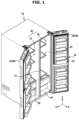
- FIG. 1 is a perspective view illustrating a refrigerator according to an embodiment of the disclosure
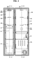
- FIG. 2 is a front view illustrating a part of a refrigerator according to an embodiment of the disclosure
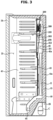
- FIG. 3 is a side cross-sectional view taken along line AA' shown in FIG. 2
- FIG. 4 is a side cross-sectional view taken along line BB' shown in FIG. 2
- FIG. 5 is a view illustrating inner cases of a freezing chamber and a refrigerating chamber and a connection duct, which is viewed from the rear, according to an embodiment of the disclosure
- FIG. 6 is a view illustrating inner cases of a freezing chamber and a refrigerating chamber, which is viewed from the rear, according to an embodiment of the disclosure.
- a refrigerator includes a main body 10, which is also referred to as an outer case) forming the external appearance, a storage chamber 20 inside the main body 10 having a front side thereof openable and accommodating a storage box 28, and the like, and a door 30 rotatably coupled to the main body 10 to open and close the front open side of the storage chamber 20.
- the main body 10 includes an inner case 40 forming the storage chamber 20 and a cold air supply device configured to supply cold air to the storage chamber 20.
- the cold air supply device may include a compressor C, a condenser (not shown), an expansion valve (not shown), and an evaporator (E), and between the main body 10 and the inner case 40 and inside the door 30, heat insulating material 15 is foamed and filled to prevent cold air from leaking out of the storage chamber 20.
- the storage chamber 20 is provided inside the main body 10 and has a front side that is openable, and the opened front side is opened and closed by the door 30.
- the storage chamber 20 may be divided into a plurality of storage chambers by a partition wall 17.
- the storage chamber 20 may include a freezing chamber 21 and a refrigerating chamber 22 partitioned in the left-right direction by the partition wall 17.
- the inner case 40 may include a freezing chamber inner case 41 forming the freezing chamber 21 and a refrigerating chamber inner case 42 forming the refrigerating chamber 22.
- the freezing chamber inner case 41 and the refrigerating chamber inner case 42 may be arranged on the left side and right side with respect to the partition wall 17.
- the storage chamber 20 is provided at a rear lower side thereof with a machine room 25 in which a compressor C for compressing a refrigerant and a condenser (not shown) for condensing the compressed refrigerant are installed.
- the storage chamber 20 may be provided therein with a plurality of shelves 27 and a storage box 28 to store food and the like.
- the door 30 is rotatably coupled to the main body 10 to open and close the open front side of the storage chamber 20.
- the freezing chamber 21 and the refrigerating chamber 22 may be opened and closed by a first door 31 and a second door 32 rotatably coupled to the main body 10, respectively.
- the refrigerator may be provided as a double-door type refrigerator
- the refrigerator may be provided as a Top Mounted Freezer (TMF) type refrigerator in which the freezing chamber 21 and the refrigerating chamber 22 are arranged on the upper side and the lower side, respectively, or as a bottom mounted freezer (BMF) in which the refrigerating chamber 22 and the freezing chamber 21 are arranged on the upper side and the lower side, respectively.
- TMF Top Mounted Freezer
- BMF bottom mounted freezer
- the disclosure is not limited thereto, and the storage chamber 20 may be divided into three or more chambers by the partition wall 17.
- a plurality of door guards 33 capable of accommodating food and the like may be provided on the rear surface of the door 30.
- the freezing chamber 21 may be provided at an inner side thereof with a freezing chamber duct 200 configured to supply cold air to the freezing chamber 21.
- the refrigerating chamber 22 may be provided at an inner side thereof with a refrigerating chamber duct 100 configured to supply cold air to the refrigerating chamber 22.
- the freezing chamber duct 200 may be arranged on the upper end of the rear side of the freezing chamber 21. At the lower side of the freezing chamber duct 200, a separating plate 43 that forms the rear surface of the freezing chamber 21 together with the freezing chamber duct 200 may be arranged.
- the freezing chamber duct 200 and the separating plate 43 may be arranged forward than a freezing chamber inner case rear surface 41a. Accordingly, a cooling space 45 may be formed by the freezing chamber duct 200, the separating plate 43, and the freezing chamber inner case rear surface 41a.
- An evaporator E may be arranged in the cooling space 45.
- a passage through which cold air generated in the evaporator E flows to the freezing chamber duct 200 may be formed.
- the freezing chamber 21 may be formed by an inner surface of the freezing chamber inner case 41, a front surface 211 of a duct plate 210 of the freezing chamber duct 200, and the separating plate 43. That is, the rear surface of the freezing chamber 21 may be formed by the front surface 211 of the duct plate 210 of the freezing chamber duct 200 and the separating plate 43, and the side surfaces of the freezing chamber 21 may be formed by inner surfaces of the freezing chamber inner case 41.
- the freezing chamber duct 200 may include the duct plate 210 and a duct cover 270 that covers a rear surface 212 of the duct plate 210 from the rear of the duct plate 210.
- the freezing chamber duct 200 may include an internal space 203 formed between the duct plate 210 and the duct cover 270.
- the freezing chamber duct 200 may include a blower fan 260 arranged on the rear surface 212 of the duct plate 210 and provided so that the cold air formed in the cooling space 45 is introduced into the freezing chamber duct 200.
- Cold air in the cooling space 45 may flow upward by the blower fan 260 and may be introduced into the freezing chamber duct 200 through the blower fan 260.
- the cold air introduced into the internal space 203 may be discharged to the freezing chamber 21 through freezing chamber discharge ports 220, 230, and 240 of the freezing chamber duct 200 by the blower fan 260.
- the cold air formed in the cooling space 45 may be formed at approximately -20 degrees, and may be directly discharged to the freezing chamber 21 by the blower fan 260 to cool the freezing chamber 21.
- the refrigerating chamber duct 100 may be arranged at an upper end of the rear side of the refrigerating chamber 22. At a lower side of the refrigerating chamber duct 100, a refrigerating chamber inner case rear surface 42a forming the rear surface of the refrigerating chamber 22 together with the refrigerating chamber duct 100 may be arranged.
- the refrigerating chamber 22 may be formed by an inner surface of the refrigerating chamber inner case 42, a front surface 111 of a duct plate 110 of the refrigerating chamber duct 100, and a rear surface 42a of the refrigerating chamber inner case. That is, the rear surface of the refrigerating chamber 22 may be formed by the front surface 111 of the duct plate 110 of the refrigerating chamber duct 100 and the refrigerating chamber inner case rear surface 42a, and the side surfaces of the refrigerating chamber 22 may formed by the inner surfaces of the refrigerating chamber inner case 42.
- a space may be formed between the duct plate 110 of the refrigerating chamber duct 100 and the refrigerating chamber inner case rear surface 42a. In the space, a passage for air introduced into the refrigerating chamber duct 100 may be formed.
- the refrigerating chamber duct 100 does not additionally include an evaporator for supplying cold air. Therefore, cold air generated by the evaporator E communicating with the freezing chamber duct 200 flows into the refrigerating chamber duct 100 through the freezing chamber duct 200 and then is discharged from the refrigerating chamber duct 100 to keep the refrigerating chamber 22 at a low temperature.
- discharge ports 120, 130, and 140 are provided for cold air flowing in an internal space 160 of the refrigerating chamber duct 100 to be discharged to the refrigerating chamber 22.
- a circulation passage 44 communicated with the machine room 25 and provided to introduce circulated cold air into the machine room 25 may be arranged at a lower side of the freezing chamber inner case 41.
- a second circulation passage (not shown) that is directly connected to the storage chamber 25 or communicates with the lower side of the freezing chamber inner case 41 may be arranged at a lower side of the refrigerating chamber inner case 42.
- connection duct 300 for connecting the freezing chamber duct 200 to the refrigerating chamber duct 100 so that the cold air inside the freezing chamber duct 200 flows to the refrigerating chamber duct 100 may be provided.
- connection duct 300 has one end 321 connected to an outlet 250 of the freezing chamber duct 200 through which cold air in the freezing chamber duct 200 flows out, and an other end 322 connected to a connector 150 of the refrigerating chamber duct 100 that is connected to the connection duct 300 so that cold air is introduced from the freezing chamber duct 200.
- the air cooled in the cooling space 45 by the blower fan 260 may flow into the freezing chamber duct 200, and a part of the cold air introduced into the freezing chamber duct 200 may be discharged through the discharge ports 220, 230, and 240 of the freezing chamber duct 200 into the freezing chamber 21, and the other part of the cold air may be introduced into the refrigerating chamber duct 100 through the connection duct 300.
- a damper 400 that selectively opens and closes the connection duct 300 may be provided at one end of the connection duct 300.
- the damper is arranged on the side of the refrigerating chamber. Specifically, the damper is arranged inside the refrigerating chamber duct, and selectively opens and closes the connector of the refrigerating chamber duct such that the other end of the connection duct selectively communicates with the refrigerating chamber duct.
- the volume of the refrigerating chamber duct increases, and in particular, the refrigerating chamber duct protrudes forward in the amount corresponding to the space in which the damper is arranged, and thus the aesthetics of the refrigerating chamber is deteriorated, and the capacity of the refrigerating chamber is reduced, thereby reducing the efficiency of the refrigerator.
- the damper 400 of the refrigerator 1 is arranged inside the freezing chamber duct 200 to secure a wider space in the refrigerating chamber 22.
- the freezing chamber duct 200 may be arranged forward than the refrigerating chamber duct 100. This is because the cooling space 45 in which the evaporator E is arranged is formed between the rear surface of the main body 10 and the freezing chamber 21.
- the length of the freezing chamber 21 in the front-rear direction X may be formed shorter than the length of the refrigerating chamber 22 in the front-rear direction X, and accordingly, the duct plate 210 of the freezing chamber duct 200 is arranged forward than the duct plate 110 of the refrigerating chamber duct 100.
- the internal space 203 of the freezing chamber duct 200 has a larger width in the front-rear direction X than that of the internal space of the refrigerating chamber duct 100.
- the damper 400 when the damper 400 is formed in the internal space 203 of the freezing chamber duct 200, the capacity loss of the freezing chamber 21 and the refrigerating chamber 22 may not occur.
- the damper 400 is formed inside the duct 100 of the refrigerating chamber 22, a portion of the front surface 111 of the duct plate 110 of the refrigerating chamber duct 100 protrudes forward by the size of the damper 400.
- the front surface 111 of the duct plate 110 of the refrigerating chamber duct 100 may be provided as a flat surface without a protruding part.
- the outlet 250 of the freezing chamber duct 200 connected to the one end 321 of the connection duct 300 is arranged on the side surface of the freezing chamber duct 200, and communicate with an opening 41b formed on the side surface of the freezing chamber inner case 41.
- the connector 150 of the refrigerating chamber duct 100 connected to the other end 322 of the connection duct 300 is arranged on the rear surface of the refrigerating chamber duct 100, and may communicate with an opening 42b formed on the rear surface of the refrigerating chamber inner case 42.
- connection duct 300 In the conventional case, the freezing chamber duct and the refrigerating chamber duct are each connected at a side surface thereof to the connection duct, but since the connection duct 300 according to an embodiment of the disclosure is arranged rearward than the freezing chamber duct 200 without a part protruding forward from the refrigerating chamber duct 100. Accordingly, the other end 322 of the connection duct 300 may be coupled to the rear surface of the refrigerating chamber duct 100.
- FIG. 7 is a view illustrating a freezing chamber duct, which is viewed from the rear according to an embodiment of the disclosure from the rear
- FIG. 8 is a rear view illustrating a state in which a duct cover is removed from a freezing chamber duct according to an embodiment of the disclosure
- FIG. 9 is a view illustrating a state in which a damper frame is removed from FIG. 8
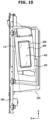
- FIG. 10 is a side view illustrating a state in which a duct cover is removed from a freezing chamber duct according to an embodiment of the disclosure
- FIG. 11 is a rear perspective view illustrating a state in which a duct cover is removed from a freezing chamber duct according to an embodiment of the disclosure.
- the damper 400 may be arranged inside the freezing chamber duct 200.
- the duct cover 270 of the freezing chamber duct 200 may include an inlet 271 that is opened to introduce air into the blower fan 260.
- the duct cover 270 may include a damper housing part 272 extending to the rear side of the duct cover 270 to cover the damper 400 and having a shape substantially similar to the external appearance of the damper 400.
- the damper housing part 272 is integrally formed with the duct cover 270, but the disclosure is not limited thereto, and the damper housing part 272 may be provided as a separate part from the duct cover 270 and coupled to the duct cover 270.
- the outlet 250 communicating with the opening 41b of the freezing chamber inner case 41 may be arranged on a side surface of the damper housing part 272.
- the damper 400 arranged inside the damper housing part 272 may selectively open and closes the outlet 250 to restrict the flow of cold air flowing in the freezing chamber duct 200 to the connection duct 300 to thereby restrict cold air from being supplied to the refrigerating chamber duct 100.
- the damper 400 includes a door 420 selectively opening and closing the outlet 250 or the one end 321 of the connection duct 300, and a driving part 430 for driving a door frame 410, to which the door 420 is rotatably coupled, and the door 420.
- the door 420 may be rotated about a rotation axis R.
- the door 420 may open the outlet 250 by rotating about the rotation axis R in a direction opposite to the connection duct 300 or in a direction in which the blower fan 260 is arranged.
- the door 420 may close the outlet 250 by rotating about the rotation axis R in the direction toward the connection duct 300. This is to drain condensate water that may be frozen between the door 420 and the door frame 410. This will be described below in detail.
- the driving part 430 may be connected to the door 420 in the direction of the rotation axis R to rotate the door 420.
- damper 400 since the damper 400 is arranged inside the freezing chamber duct 200, condensate water may be frozen inside the damper 400.
- the freezing chamber duct 200 is supplied with cold air of about -20 degrees so that water vapor in the air flowing inside the refrigerator 1 may collide with the damper 400 to generate condensate water, and the condensate water having collided with the damper 400 400 may be frozen inside the duct 400 by the low temperature formed inside the freezing chamber duct 200.
- the door 420 when condensate water is frozen between the door 420 and the door frame 410, the door 420 may be restricted in rotation and the damper 400 may be caused to malfunction.
- the damper 400 may arranged to be inclined with respect to an upper-lower direction Z so that when condensate water is generated inside the damper 400, the condensed water is easily drained.
- the damper 400 may be arranged at a predetermined angle ⁇ 1 in a left-right direction Y perpendicular to the upper-lower direction Z.
- one surface 410a of the door frame 410 arranged adjacent to the blower fan 260 may be arranged at a predetermined angle ⁇ 1 in the left-right direction Y perpendicular to the upper-lower direction Z. This is because, in the damper 400, the one surface 410a of the door frame 410 facing the blower fan 260 is a region where the most collision with the circulated air occurs.
- an opening 411 (see FIG. 11 ) formed on the one surface 410a of the door frame 410 is slantingly formed at the predetermined angle ⁇ 1 in the left-right direction Y perpendicular to the upper-lower direction Z.
- Condensate water colliding with the one surface 410a of the door frame 410 facing the blower fan 260, the area of the door frame 410 at an inner side of the opening 411 of the one surface 410a, and the door 420 may flow to the lower end of the door frame 410 due to the slope in the left-right direction Y perpendicular to the upper-lower direction Z.
- the condensate water may flow to the lowermost end in the upper-lower direction Z and the left-right direction Y along the slope.
- the other surface 410b arranged on the opposite side of the one surface 410a of the door frame 410 may be arranged parallel to the upper-lower direction Z.
- the disclosure is not limited thereto, and the other surface 410b may be arranged parallel to the one surface 410a.
- the damper 400 may be additionally obliquely arranged at a predetermined angle ⁇ 2 in the front-rear direction X perpendicular to the upper-lower direction Z.
- the door frame 410 may extend to be inclined at a predetermined angle ⁇ 2 in the front-rear direction X perpendicular to the extension direction Z of the duct plate 410.
- the openings 411 and 412 formed on the both surfaces 410a and 410b of the door frame 410 are all inclined at the predetermined angle ⁇ 2 in the front-rear direction X perpendicular to the extension direction Z.
- Condensate water colliding with the one surface 410a and the other surface 410b of the door frame 410, the area of the door frame 410 formed inside the opening 411 of the one surface 410a and the opening 412 of the other surface 410b, and the door 420 may flow to the lower end of the door frame 410 by the slope in the front-rear direction X perpendicular to the upper-lower direction Z.
- the damper 400 may be arranged to be inclined with three-dimensions. Accordingly, when condensate water is generated inside the damper 400, in detail, on the door 420 or the door frame 410, the condensate water may be easily drained to the lowermost end in the front-rear direction X and left-right direction Y of the damper 400 along the slope.
- the door frame 410 may include a drain part 413 arranged at the lowermost end in the front-rear direction X and the left-right direction Y.
- the opening 411 of the one surface 410a is provided at an inner side with a guide part 414 provided to guide the condensate water formed inside the door frame 410 to the drain part 413.
- the guide part 414 may be a region extending from a region in which the door 420 is arranged to the opening 411 on the one surface 410a, and may be formed to be inclined in the front-rear direction X and the left-right direction Y with respect to the upper-lower direction Z.
- condensate water formed due to collision within the door 420 or the inner side of the door frame 410 may be gathered in the drain part 413 along the slope of the guide unit 414.
- condensate water formed by colliding with the one surface 410a of the door frame 410 may be gathered in the drain part 413 along the slope because the one surface 410a is also formed to be inclined.
- the drain part 413 may include a shape that is cut downward such that the condensate water collected on the drain part 413 is fallen.
- the region corresponding to the position of the drain part 413 in the damper housing part 272 covering the door frame 410 may include a cut-out shape so that the drain part 413 communicates with the outside.
- the condensate water collected in the drain part 413 may be drained to the outside of the damper 400 and the freezing chamber duct 200.
- the evaporator E may be arranged at a lower side of the freezing chamber duct 200 (see FIG. 3 ). Accordingly, the condensate water dripping from the drain part 413 reaches the surface of the evaporator E, and the condensate water may be frozen on the evaporator E.
- the condensate water frozen on the evaporator E may be defrosted by heat generated in the evaporator E during a defrosting process of the refrigerator 1.
- condensate water generated inside the damper 400 may be easily frozen due to the low temperature inside the freezing chamber duct 200, but since the damper 400 is arranged to be inclined, the generated condensate water may be easily drained outside of the damper 400 and the freezing chamber duct 200 along the slope, so that the damper 400 may be stably driven.
- connection duct 300 according to an embodiment of the disclosure will be described in detail.
- FIG. 12 is an exploded perspective view illustrating a connection duct according to an embodiment of the disclosure.
- connection duct 300 may connect the freezing chamber duct 200 to the refrigerating chamber duct 100 as described above.
- connection duct 300 may be coupled to the freezing chamber inner case 41 and communicate with the outlet 250 of the freezing chamber duct 200 through the opening 41b of the freezing chamber inner case 41.
- connection duct 300 may be coupled to the refrigerating chamber inner case 42 and may communicate with the connector 150 of the refrigerating chamber duct 100 through the opening 42b of the refrigerating chamber inner case 42.
- a region between the one end 321 and the other end 322 of the connection duct 300 may be provided in a shape including a curved surface to facilitate the flow of air flowing in the connection duct 300.
- each of the one end 321 and the other end 322 of the connection duct 300 may include an opening formed at an inside thereof and provided to communicate with the internal air passage of the connection duct 300.
- connection duct 300 may be provided in a shape in which a first housing 310 and a second housing 320 are coupled to each other.
- the one end 321 and the other end 322 of the connection duct 300 may be formed on the second housing 320.
- connection duct 300 may be formed by the first housing 310, and may be formed by assembling the first housing 310 and the second housing 320.
- an air flow passage may be formed between the first housing 310 and the second housing 320.
- connection duct 300 may include a rib 330 arranged inside the air passage.
- a freezing of condensate water may occur on the damper 400.
- the freezing is a freezing that is generated by condensate water contained in air circulated by the blower fan 260.
- water vapor in the air inside the refrigerating chamber 22 may move toward the damper 400 and collide with the door 420 of the damper 400 or the other surface 410b of the door frame 410 to form condensate water.
- connection duct 300 in order to prevent water vapor in the air flowing from the side of the refrigerating chamber 22 to the connection duct 300 from colliding with the damper 400 and freezing inside the damper 400, may include the rib 330 arranged on the air passage inside the connection duct 300.
- the rib 330 may be provided in a shape, a cross-sectional area of which gradually increases from the one end 321 of the connection duct 300 to the other end 322 of the connection duct 300.
- the flow of air from the refrigerating chamber duct 100 to the freezing chamber duct 200 may be limited by the shape of the rib 330.
- the rib 330 may be provided in a shape extending in a direction opposite to the direction from the refrigerating chamber duct 100 to the freezing chamber duct 200.
- a portion of the air flowing into the freezing chamber duct 200 may be blocked by the rib 330 without reaching the damper 400, but may flow back to the refrigerating chamber duct 100.
- the rib 330 may include a collecting part 331 capable of collecting condensate water generated due to collision of air.
- the direction of the air flow may be changed, and at the same time as the collision, condensate water may be generated, and the condensate water may be collected in the collecting part 331.
- the flow of the air may be switched before reaching the damper 400 by the rib 330, or moisture in the air may be collected by the collecting part 331 of the rib 330 so that moisture is prevented from reaching the damper 400.
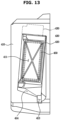
- FIG. 13 is a view illustrating a damper according to another embodiment of the disclosure.
- the damper 400 may include a heating wire 450 installed into a contact portion 415 that is in contact with a surface of the door 420 when the door 420 is closed.
- a malfunction may occur in the driving part 430 and the driving part 430 may be damaged, and the temperature of the refrigerating chamber 22 may not be controlled.
- ice formation occurring between the contact portion 415 and the door 420 may be the greatest concern.
- the damper 400 includes the heating wire 450 installed into the contact portion 415 to eliminate the limitation.
- the heating wire 450 may be periodically driven to perform defrosting on the contact portion15, or when a malfunction occurs in the driving part 430, the heating wire 450 may be driven through a controller (not shown) to defrost the contact portion 415.
Landscapes
- Engineering & Computer Science (AREA)
- Chemical & Material Sciences (AREA)
- Combustion & Propulsion (AREA)
- Physics & Mathematics (AREA)
- Mechanical Engineering (AREA)
- Thermal Sciences (AREA)
- General Engineering & Computer Science (AREA)
- Cold Air Circulating Systems And Constructional Details In Refrigerators (AREA)
Description
- The disclosure relates to a refrigerator for controlling the temperature of a storage chamber through a single evaporator.
- A refrigerator is a home appliance that is equipped with a main body having a storage chamber, a cold air supply device provided to supply cold air to the storage chamber, and a door provided to open and close the storage chamber so that food is kept in a fresh state. The storage chamber includes a refrigerating chamber maintained at about 0°C to 5°C to store food refrigerated, and a freezing chamber maintained at about 0°C to -30°C to store food frozen.
- The refrigerator may be classified according to the positions of the refrigerating chamber and the freezing chamber into a Bottom Mounted Freezer (BMF)-type refrigerator provided with a freezing chamber at the lower side and a refrigerating chamber formed at the upper side, a Top Mounted Freezer (TMP)-type refrigerator provided with a freezing chamber formed at the upper side and a refrigerating chamber formed at the lower side, and a Side By Side (SBS)-type refrigerator provided with the freezing chamber and the refrigerating chamber laterally arranged in a left-right direction. Further, the refrigerator may be classified according to the number of doors into a two-door refrigerator, a three-door refrigerator, and a four-door refrigerator.
- In order to supply cold air to the refrigerating chamber and the freezing chamber, an evaporator may be installed in each of the refrigerating chamber and the freezing chamber. In addition, cold air may be supplied to the refrigerating chamber and the freezing chamber through a single evaporator.
- Exemplary embodiments of refrigerators of the prior art are disclosed in
JP H10 68573 A KR 2015 0053064 CN 108 548 355 A ,KR 101 408 769 B1 CN 105 042 990 A andCN 107 300 288 A . - The present invention is directed to providing a refrigerator in which cold air is supplied to a refrigerating chamber and a freezing chamber through a single evaporator so that a cold air supply device is provided with a simple structure.
- The present invention is directed to providing a refrigerator having an improved structure in which a damper provided to maintain a temperature difference between a refrigerating chamber and a refrigerating chamber duct is arranged inside a freezing chamber.
- The present invention is directed to subject matter as defined in the claims.
- According to an embodiment of the disclosure, a damper arranged between a refrigerating chamber duct and a freezing chamber duct is arranged on a side of the freezing chamber so that the capacity of the refrigerating chamber can be increased. With respect to dew condensation that may occur due to the duct being arranged on the side of the freezing chamber, the damper is slantingly arranged with respect to the vertical direction so that condensate water can be easily drained to prevent dew condensation.
-
-
FIG. 1 is a perspective view illustrating a refrigerator according to an embodiment of the disclosure; -
FIG. 2 is a front view illustrating a part of a refrigerator according to an embodiment of the disclosure; -
FIG. 3 is a side cross-sectional view taken along line AA' shown inFIG. 2 ; -
FIG. 4 is a side cross-sectional view taken along line BB' shown inFIG. 2 ; -
FIG. 5 is a view illustrating inner cases of a freezing chamber and a refrigerating chamber and a connection duct, which is viewed from the rear, according to an embodiment of the disclosure. -
FIG. 6 is a view illustrating inner cases of a freezing chamber and a refrigerating chamber, which is viewed from the rear, according to an embodiment of the disclosure. -
FIG. 7 is a view illustrating a freezing chamber duct, which is viewed from the rear, according to an embodiment of the disclosure. -
FIG. 8 is a rear view illustrating a state in which a duct cover is removed from a freezing chamber duct according to an embodiment of the disclosure; -
FIG. 9 is a view illustrating a state in which a damper frame is removed fromFIG. 8 ; -
FIG. 10 is a side view illustrating a state in which a duct cover is removed from a freezing chamber duct according to an embodiment of the disclosure. -
FIG. 11 is a rear perspective view illustrating a state in which a duct cover is removed from a freezing chamber duct according to an embodiment of the disclosure. -
FIG. 12 is an exploded perspective view illustrating a connection duct according to an embodiment of the disclosure. -
FIG. 13 is a view illustrating a damper according to another embodiment of the disclosure. - Throughout the drawings, like reference numerals refer to like parts or components.
- The terminology used herein is for the purpose of describing particular embodiments only and is not intended to limit the disclosure. It is to be understood that the singular forms "a," "an," and "the" include plural references unless the context clearly dictates otherwise. It will be further understood that the terms "include", "comprise" and/or "have" when used in this specification, specify the presence of stated features, integers, steps, operations, elements, and/or components, but do not preclude the presence or addition of one or more other features, integers, steps, operations, elements, components, and/or groups thereof.
- The terms including ordinal numbers like "first" and "second" may be used to explain various components, but the components are not limited by the terms. The terms are only for the purpose of distinguishing a component from another. Thus, a first element, component, region, layer or section discussed below could be termed a second element, component, region, layer or section without departing from the teachings of the disclosure. Descriptions shall be understood as to include any and all combinations of one or more of the associated listed items when the items are described by using the conjunctive term "~ and/or ~," or the like.
- The terms "front", "rear", "upper", "lower", "top", and "bottom" as herein used are defined with respect to the drawings, but the terms may not restrict the shape and position of the respective components.
- Hereinafter, embodiments of the disclosure will be described in detail with reference to the accompanying drawings.
-
FIG. 1 is a perspective view illustrating a refrigerator according to an embodiment of the disclosure,FIG. 2 is a front view illustrating a part of a refrigerator according to an embodiment of the disclosure,FIG. 3 is a side cross-sectional view taken along line AA' shown inFIG. 2 ,FIG. 4 is a side cross-sectional view taken along line BB' shown inFIG. 2 , andFIG. 5 is a view illustrating inner cases of a freezing chamber and a refrigerating chamber and a connection duct, which is viewed from the rear, according to an embodiment of the disclosure,FIG. 6 is a view illustrating inner cases of a freezing chamber and a refrigerating chamber, which is viewed from the rear, according to an embodiment of the disclosure. - Referring to
FIGS. 1 to 4 , a refrigerator includes amain body 10, which is also referred to as an outer case) forming the external appearance, astorage chamber 20 inside themain body 10 having a front side thereof openable and accommodating astorage box 28, and the like, and adoor 30 rotatably coupled to themain body 10 to open and close the front open side of thestorage chamber 20. - The
main body 10 includes aninner case 40 forming thestorage chamber 20 and a cold air supply device configured to supply cold air to thestorage chamber 20. - The cold air supply device may include a compressor C, a condenser (not shown), an expansion valve (not shown), and an evaporator (E), and between the
main body 10 and theinner case 40 and inside thedoor 30,heat insulating material 15 is foamed and filled to prevent cold air from leaking out of thestorage chamber 20. - The
storage chamber 20 is provided inside themain body 10 and has a front side that is openable, and the opened front side is opened and closed by thedoor 30. - The
storage chamber 20 may be divided into a plurality of storage chambers by apartition wall 17. Thestorage chamber 20 may include afreezing chamber 21 and a refrigeratingchamber 22 partitioned in the left-right direction by thepartition wall 17. - The
inner case 40 may include a freezing chamberinner case 41 forming thefreezing chamber 21 and a refrigerating chamberinner case 42 forming the refrigeratingchamber 22. The freezing chamberinner case 41 and the refrigerating chamberinner case 42 may be arranged on the left side and right side with respect to thepartition wall 17. - The
storage chamber 20 is provided at a rear lower side thereof with amachine room 25 in which a compressor C for compressing a refrigerant and a condenser (not shown) for condensing the compressed refrigerant are installed. - The
storage chamber 20 may be provided therein with a plurality ofshelves 27 and astorage box 28 to store food and the like. - The
door 30 is rotatably coupled to themain body 10 to open and close the open front side of thestorage chamber 20. Thefreezing chamber 21 and the refrigeratingchamber 22 may be opened and closed by afirst door 31 and asecond door 32 rotatably coupled to themain body 10, respectively. - Although the refrigerator according to an embodiment of the disclosure may be provided as a double-door type refrigerator, the refrigerator may be provided as a Top Mounted Freezer (TMF) type refrigerator in which the
freezing chamber 21 and the refrigeratingchamber 22 are arranged on the upper side and the lower side, respectively, or as a bottom mounted freezer (BMF) in which the refrigeratingchamber 22 and thefreezing chamber 21 are arranged on the upper side and the lower side, respectively. - In addition, the disclosure is not limited thereto, and the
storage chamber 20 may be divided into three or more chambers by thepartition wall 17. - A plurality of
door guards 33 capable of accommodating food and the like may be provided on the rear surface of thedoor 30. - The
freezing chamber 21 may be provided at an inner side thereof with afreezing chamber duct 200 configured to supply cold air to thefreezing chamber 21. The refrigeratingchamber 22 may be provided at an inner side thereof with a refrigeratingchamber duct 100 configured to supply cold air to the refrigeratingchamber 22. - The
freezing chamber duct 200 may be arranged on the upper end of the rear side of thefreezing chamber 21. At the lower side of thefreezing chamber duct 200, aseparating plate 43 that forms the rear surface of thefreezing chamber 21 together with thefreezing chamber duct 200 may be arranged. - The
freezing chamber duct 200 and the separatingplate 43 may be arranged forward than a freezing chamber inner caserear surface 41a. Accordingly, acooling space 45 may be formed by thefreezing chamber duct 200, the separatingplate 43, and the freezing chamber inner caserear surface 41a. - An evaporator E may be arranged in the cooling
space 45. In addition, a passage through which cold air generated in the evaporator E flows to the freezingchamber duct 200 may be formed. - The freezing
chamber 21 may be formed by an inner surface of the freezing chamberinner case 41, afront surface 211 of aduct plate 210 of the freezingchamber duct 200, and the separatingplate 43. That is, the rear surface of the freezingchamber 21 may be formed by thefront surface 211 of theduct plate 210 of the freezingchamber duct 200 and the separatingplate 43, and the side surfaces of the freezingchamber 21 may be formed by inner surfaces of the freezing chamberinner case 41. - The freezing
chamber duct 200 may include theduct plate 210 and aduct cover 270 that covers arear surface 212 of theduct plate 210 from the rear of theduct plate 210. In addition, the freezingchamber duct 200 may include aninternal space 203 formed between theduct plate 210 and theduct cover 270. - The freezing
chamber duct 200 may include ablower fan 260 arranged on therear surface 212 of theduct plate 210 and provided so that the cold air formed in the coolingspace 45 is introduced into the freezingchamber duct 200. - Cold air in the cooling
space 45 may flow upward by theblower fan 260 and may be introduced into the freezingchamber duct 200 through theblower fan 260. - The cold air introduced into the
internal space 203 may be discharged to the freezingchamber 21 through freezingchamber discharge ports chamber duct 200 by theblower fan 260. - The cold air formed in the cooling
space 45 may be formed at approximately -20 degrees, and may be directly discharged to the freezingchamber 21 by theblower fan 260 to cool the freezingchamber 21. - The refrigerating
chamber duct 100 may be arranged at an upper end of the rear side of the refrigeratingchamber 22. At a lower side of the refrigeratingchamber duct 100, a refrigerating chamber inner caserear surface 42a forming the rear surface of the refrigeratingchamber 22 together with the refrigeratingchamber duct 100 may be arranged. - The refrigerating
chamber 22 may be formed by an inner surface of the refrigerating chamberinner case 42, afront surface 111 of aduct plate 110 of the refrigeratingchamber duct 100, and arear surface 42a of the refrigerating chamber inner case. That is, the rear surface of the refrigeratingchamber 22 may be formed by thefront surface 111 of theduct plate 110 of the refrigeratingchamber duct 100 and the refrigerating chamber inner caserear surface 42a, and the side surfaces of the refrigeratingchamber 22 may formed by the inner surfaces of the refrigerating chamberinner case 42. - A space may be formed between the
duct plate 110 of the refrigeratingchamber duct 100 and the refrigerating chamber inner caserear surface 42a. In the space, a passage for air introduced into the refrigeratingchamber duct 100 may be formed. - The refrigerating
chamber duct 100 does not additionally include an evaporator for supplying cold air. Therefore, cold air generated by the evaporator E communicating with the freezingchamber duct 200 flows into the refrigeratingchamber duct 100 through the freezingchamber duct 200 and then is discharged from the refrigeratingchamber duct 100 to keep the refrigeratingchamber 22 at a low temperature. - On the
front surface 111 of theduct plate 110 of the refrigeratingchamber duct 100,discharge ports internal space 160 of the refrigeratingchamber duct 100 to be discharged to the refrigeratingchamber 22. - A
circulation passage 44 communicated with themachine room 25 and provided to introduce circulated cold air into themachine room 25 may be arranged at a lower side of the freezing chamberinner case 41. - A second circulation passage (not shown) that is directly connected to the
storage chamber 25 or communicates with the lower side of the freezing chamberinner case 41 may be arranged at a lower side of the refrigerating chamberinner case 42. - The cold air circulated in the freezing
chamber 21 and the refrigeratingchamber 22 through thecirculation passage 44 and the second circulation passage (not shown) flows back into themachine chamber 25 so that the cold air is supplied to the freezingchamber 21 and the refrigeratingchamber 22 through a single evaporator E. - Referring to
FIGS. 5 and6 , between the freezingchamber duct 200 and the refrigeratingchamber duct 100, aconnection duct 300 for connecting the freezingchamber duct 200 to the refrigeratingchamber duct 100 so that the cold air inside the freezingchamber duct 200 flows to the refrigeratingchamber duct 100 may be provided. - The
connection duct 300 has oneend 321 connected to anoutlet 250 of the freezingchamber duct 200 through which cold air in the freezingchamber duct 200 flows out, and another end 322 connected to aconnector 150 of the refrigeratingchamber duct 100 that is connected to theconnection duct 300 so that cold air is introduced from the freezingchamber duct 200. - The air cooled in the cooling
space 45 by theblower fan 260 may flow into the freezingchamber duct 200, and a part of the cold air introduced into the freezingchamber duct 200 may be discharged through thedischarge ports chamber duct 200 into the freezingchamber 21, and the other part of the cold air may be introduced into the refrigeratingchamber duct 100 through theconnection duct 300. - As described above, the cold air formed in the cooling
space 45 maintains a temperature of about -20 degrees, but the refrigeratingchamber 22 needs to maintain a temperature of about 0 degrees or more. Therefore, to prevent additional low-temperature cold air from flowing into the refrigeratingchamber 22 when the internal temperature of the refrigeratingchamber 22 is maintained at about 0 degrees, adamper 400 that selectively opens and closes theconnection duct 300 may be provided at one end of theconnection duct 300. - In the conventional case, the damper is arranged on the side of the refrigerating chamber. Specifically, the damper is arranged inside the refrigerating chamber duct, and selectively opens and closes the connector of the refrigerating chamber duct such that the other end of the connection duct selectively communicates with the refrigerating chamber duct.
- Accordingly, the volume of the refrigerating chamber duct increases, and in particular, the refrigerating chamber duct protrudes forward in the amount corresponding to the space in which the damper is arranged, and thus the aesthetics of the refrigerating chamber is deteriorated, and the capacity of the refrigerating chamber is reduced, thereby reducing the efficiency of the refrigerator.
- In order to solve the limitation, the
damper 400 of the refrigerator 1 according to an embodiment of the disclosure is arranged inside the freezingchamber duct 200 to secure a wider space in the refrigeratingchamber 22. - The freezing
chamber duct 200 may be arranged forward than the refrigeratingchamber duct 100. This is because the coolingspace 45 in which the evaporator E is arranged is formed between the rear surface of themain body 10 and the freezingchamber 21. - That is, the length of the freezing
chamber 21 in the front-rear direction X may be formed shorter than the length of the refrigeratingchamber 22 in the front-rear direction X, and accordingly, theduct plate 210 of the freezingchamber duct 200 is arranged forward than theduct plate 110 of the refrigeratingchamber duct 100. - As the
duct plate 210 of the freezingchamber duct 200 is arranged forward than theduct plate 110 of the refrigeratingchamber duct 100, theinternal space 203 of the freezingchamber duct 200 has a larger width in the front-rear direction X than that of the internal space of the refrigeratingchamber duct 100. - Accordingly, when the
damper 400 is formed in theinternal space 203 of the freezingchamber duct 200, the capacity loss of the freezingchamber 21 and the refrigeratingchamber 22 may not occur. - In particular, in the conventional case, as the
damper 400 is formed inside theduct 100 of the refrigeratingchamber 22, a portion of thefront surface 111 of theduct plate 110 of the refrigeratingchamber duct 100 protrudes forward by the size of thedamper 400. However, according to an embodiment of the disclosure, thefront surface 111 of theduct plate 110 of the refrigeratingchamber duct 100 may be provided as a flat surface without a protruding part. - The
outlet 250 of the freezingchamber duct 200 connected to the oneend 321 of theconnection duct 300 is arranged on the side surface of the freezingchamber duct 200, and communicate with anopening 41b formed on the side surface of the freezing chamberinner case 41. - The
connector 150 of the refrigeratingchamber duct 100 connected to theother end 322 of theconnection duct 300 is arranged on the rear surface of the refrigeratingchamber duct 100, and may communicate with anopening 42b formed on the rear surface of the refrigerating chamberinner case 42. - In the conventional case, the freezing chamber duct and the refrigerating chamber duct are each connected at a side surface thereof to the connection duct, but since the
connection duct 300 according to an embodiment of the disclosure is arranged rearward than the freezingchamber duct 200 without a part protruding forward from the refrigeratingchamber duct 100. Accordingly, theother end 322 of theconnection duct 300 may be coupled to the rear surface of the refrigeratingchamber duct 100. - Hereinafter, the
damper 400 will be described in detail. -
FIG. 7 is a view illustrating a freezing chamber duct, which is viewed from the rear according to an embodiment of the disclosure from the rear,FIG. 8 is a rear view illustrating a state in which a duct cover is removed from a freezing chamber duct according to an embodiment of the disclosure,FIG. 9 is a view illustrating a state in which a damper frame is removed fromFIG. 8 ,FIG. 10 is a side view illustrating a state in which a duct cover is removed from a freezing chamber duct according to an embodiment of the disclosure, andFIG. 11 is a rear perspective view illustrating a state in which a duct cover is removed from a freezing chamber duct according to an embodiment of the disclosure. - Referring to
FIGS. 7 to 9 , thedamper 400 may be arranged inside the freezingchamber duct 200. - The
duct cover 270 of the freezingchamber duct 200 may include aninlet 271 that is opened to introduce air into theblower fan 260. - The
duct cover 270 may include adamper housing part 272 extending to the rear side of theduct cover 270 to cover thedamper 400 and having a shape substantially similar to the external appearance of thedamper 400. - The
damper housing part 272 is integrally formed with theduct cover 270, but the disclosure is not limited thereto, and thedamper housing part 272 may be provided as a separate part from theduct cover 270 and coupled to theduct cover 270. - The
outlet 250 communicating with theopening 41b of the freezing chamberinner case 41 may be arranged on a side surface of thedamper housing part 272. Thedamper 400 arranged inside thedamper housing part 272 may selectively open and closes theoutlet 250 to restrict the flow of cold air flowing in the freezingchamber duct 200 to theconnection duct 300 to thereby restrict cold air from being supplied to the refrigeratingchamber duct 100. - The
damper 400 includes adoor 420 selectively opening and closing theoutlet 250 or the oneend 321 of theconnection duct 300, and a drivingpart 430 for driving adoor frame 410, to which thedoor 420 is rotatably coupled, and thedoor 420. - The
door 420 may be rotated about a rotation axis R. Thedoor 420 may open theoutlet 250 by rotating about the rotation axis R in a direction opposite to theconnection duct 300 or in a direction in which theblower fan 260 is arranged. - In addition, the
door 420 may close theoutlet 250 by rotating about the rotation axis R in the direction toward theconnection duct 300. This is to drain condensate water that may be frozen between thedoor 420 and thedoor frame 410. This will be described below in detail. - The driving
part 430 may be connected to thedoor 420 in the direction of the rotation axis R to rotate thedoor 420. - Unlike the conventional technology, since the
damper 400 is arranged inside the freezingchamber duct 200, condensate water may be frozen inside thedamper 400. - Different from the refrigerating
chamber duct 100, the freezingchamber duct 200 is supplied with cold air of about -20 degrees so that water vapor in the air flowing inside the refrigerator 1 may collide with thedamper 400 to generate condensate water, and the condensate water having collided with thedamper 400 400 may be frozen inside theduct 400 by the low temperature formed inside the freezingchamber duct 200. - In particular, when condensate water is frozen between the
door 420 and thedoor frame 410, thedoor 420 may be restricted in rotation and thedamper 400 may be caused to malfunction. - Accordingly, the
damper 400 according to an embodiment of the disclosure may arranged to be inclined with respect to an upper-lower direction Z so that when condensate water is generated inside thedamper 400, the condensed water is easily drained. - In detail, referring to
FIGS. 8 and9 , thedamper 400 may be arranged at a predetermined angle θ1 in a left-right direction Y perpendicular to the upper-lower direction Z. - In particular, in the
door frame 410, onesurface 410a of thedoor frame 410 arranged adjacent to theblower fan 260 may be arranged at a predetermined angle θ1 in the left-right direction Y perpendicular to the upper-lower direction Z. This is because, in thedamper 400, the onesurface 410a of thedoor frame 410 facing theblower fan 260 is a region where the most collision with the circulated air occurs. - Accordingly, an opening 411 (see
FIG. 11 ) formed on the onesurface 410a of thedoor frame 410 is slantingly formed at the predetermined angle θ1 in the left-right direction Y perpendicular to the upper-lower direction Z. - Condensate water colliding with the one
surface 410a of thedoor frame 410 facing theblower fan 260, the area of thedoor frame 410 at an inner side of theopening 411 of the onesurface 410a, and thedoor 420 may flow to the lower end of thedoor frame 410 due to the slope in the left-right direction Y perpendicular to the upper-lower direction Z. - As the
damper 400 is arranged to be inclined in the left-right direction Y perpendicular to the upper-lower direction Z, the condensate water may flow to the lowermost end in the upper-lower direction Z and the left-right direction Y along the slope. - The
other surface 410b arranged on the opposite side of the onesurface 410a of thedoor frame 410 may be arranged parallel to the upper-lower direction Z. However, the disclosure is not limited thereto, and theother surface 410b may be arranged parallel to the onesurface 410a. - In addition, referring to
FIG. 10 , thedamper 400 may be additionally obliquely arranged at a predetermined angle θ2 in the front-rear direction X perpendicular to the upper-lower direction Z. - In detail, the
door frame 410 may extend to be inclined at a predetermined angle θ2 in the front-rear direction X perpendicular to the extension direction Z of theduct plate 410. - Accordingly, the
openings surfaces door frame 410 are all inclined at the predetermined angle θ2 in the front-rear direction X perpendicular to the extension direction Z. - Condensate water colliding with the one
surface 410a and theother surface 410b of thedoor frame 410, the area of thedoor frame 410 formed inside theopening 411 of the onesurface 410a and theopening 412 of theother surface 410b, and thedoor 420 may flow to the lower end of thedoor frame 410 by the slope in the front-rear direction X perpendicular to the upper-lower direction Z. - The
damper 400 may be arranged to be inclined with three-dimensions. Accordingly, when condensate water is generated inside thedamper 400, in detail, on thedoor 420 or thedoor frame 410, the condensate water may be easily drained to the lowermost end in the front-rear direction X and left-right direction Y of thedamper 400 along the slope. - In detail, referring to
FIG. 11 , thedoor frame 410 may include adrain part 413 arranged at the lowermost end in the front-rear direction X and the left-right direction Y. - The
opening 411 of the onesurface 410a is provided at an inner side with aguide part 414 provided to guide the condensate water formed inside thedoor frame 410 to thedrain part 413. - The
guide part 414 may be a region extending from a region in which thedoor 420 is arranged to theopening 411 on the onesurface 410a, and may be formed to be inclined in the front-rear direction X and the left-right direction Y with respect to the upper-lower direction Z. - Accordingly, condensate water formed due to collision within the
door 420 or the inner side of thedoor frame 410 may be gathered in thedrain part 413 along the slope of theguide unit 414. - In addition, condensate water formed by colliding with the one
surface 410a of thedoor frame 410 may be gathered in thedrain part 413 along the slope because the onesurface 410a is also formed to be inclined. - The
drain part 413 may include a shape that is cut downward such that the condensate water collected on thedrain part 413 is fallen. - Although not shown in the drawings, the region corresponding to the position of the
drain part 413 in thedamper housing part 272 covering thedoor frame 410 may include a cut-out shape so that thedrain part 413 communicates with the outside. - Accordingly, the condensate water collected in the
drain part 413 may be drained to the outside of thedamper 400 and the freezingchamber duct 200. - As described above, the evaporator E may be arranged at a lower side of the freezing chamber duct 200 (see
FIG. 3 ). Accordingly, the condensate water dripping from thedrain part 413 reaches the surface of the evaporator E, and the condensate water may be frozen on the evaporator E. - The condensate water frozen on the evaporator E may be defrosted by heat generated in the evaporator E during a defrosting process of the refrigerator 1.
- As described above, condensate water generated inside the
damper 400 may be easily frozen due to the low temperature inside the freezingchamber duct 200, but since thedamper 400 is arranged to be inclined, the generated condensate water may be easily drained outside of thedamper 400 and the freezingchamber duct 200 along the slope, so that thedamper 400 may be stably driven. - Hereinafter, the
connection duct 300 according to an embodiment of the disclosure will be described in detail. -
FIG. 12 is an exploded perspective view illustrating a connection duct according to an embodiment of the disclosure. - The
connection duct 300 may connect the freezingchamber duct 200 to the refrigeratingchamber duct 100 as described above. - One
end 321 of theconnection duct 300 may be coupled to the freezing chamberinner case 41 and communicate with theoutlet 250 of the freezingchamber duct 200 through theopening 41b of the freezing chamberinner case 41. - The
other end 322 of theconnection duct 300 may be coupled to the refrigerating chamberinner case 42 and may communicate with theconnector 150 of the refrigeratingchamber duct 100 through theopening 42b of the refrigerating chamberinner case 42. - A region between the one
end 321 and theother end 322 of theconnection duct 300 may be provided in a shape including a curved surface to facilitate the flow of air flowing in theconnection duct 300. - Although not shown in the drawings, each of the one
end 321 and theother end 322 of theconnection duct 300 may include an opening formed at an inside thereof and provided to communicate with the internal air passage of theconnection duct 300. - The
connection duct 300 may be provided in a shape in which afirst housing 310 and asecond housing 320 are coupled to each other. The oneend 321 and theother end 322 of theconnection duct 300 may be formed on thesecond housing 320. - However, the disclosure is not limited thereto, and the one
end 321 and theother end 322 of theconnection duct 300 may be formed by thefirst housing 310, and may be formed by assembling thefirst housing 310 and thesecond housing 320. - As the
first housing 310 is coupled to thesecond housing 320, an air flow passage may be formed between thefirst housing 310 and thesecond housing 320. - The
connection duct 300 may include arib 330 arranged inside the air passage. - As described above, a freezing of condensate water may occur on the
damper 400. The freezing is a freezing that is generated by condensate water contained in air circulated by theblower fan 260. - However, unlike the above, when the
door 420 of thedamper 400 is in a closed state, air inside the refrigeratingchamber 22 may be reversely introduced into the side of thedamper 400 through theconnection duct 300. - In this case, water vapor in the air inside the refrigerating
chamber 22 may move toward thedamper 400 and collide with thedoor 420 of thedamper 400 or theother surface 410b of thedoor frame 410 to form condensate water. - In particular, when condensed water is formed between the inside of the
opening 412 of theother surface 410b of thedoor 420 and thedoor 420 and frozen, thedoor 420 is restricted from being driven. - The
connection duct 300 according to an embodiment of the disclosure, in order to prevent water vapor in the air flowing from the side of the refrigeratingchamber 22 to theconnection duct 300 from colliding with thedamper 400 and freezing inside thedamper 400, may include therib 330 arranged on the air passage inside theconnection duct 300. - The
rib 330 may be provided in a shape, a cross-sectional area of which gradually increases from the oneend 321 of theconnection duct 300 to theother end 322 of theconnection duct 300. - This is to minimize the restriction of the flow of air while air flows from the freezing
chamber duct 200 to the refrigeratingchamber duct 100 by theblower fan 260. - Conversely, when the
door 420 is closed, the flow of air from the refrigeratingchamber duct 100 to the freezingchamber duct 200 may be limited by the shape of therib 330. - The
rib 330 may be provided in a shape extending in a direction opposite to the direction from the refrigeratingchamber duct 100 to the freezingchamber duct 200. - Accordingly, a portion of the air flowing into the freezing
chamber duct 200 may be blocked by therib 330 without reaching thedamper 400, but may flow back to the refrigeratingchamber duct 100. - In addition, the
rib 330 may include a collectingpart 331 capable of collecting condensate water generated due to collision of air. - Accordingly, when the air flowing into the freezing
chamber duct 200 collides with theribs 330, the direction of the air flow may be changed, and at the same time as the collision, condensate water may be generated, and the condensate water may be collected in the collectingpart 331. - That is, in the case of air flowing in the refrigerating
chamber duct 100, the flow of the air may be switched before reaching thedamper 400 by therib 330, or moisture in the air may be collected by the collectingpart 331 of therib 330 so that moisture is prevented from reaching thedamper 400. - Hereinafter, a
damper 400 of the refrigerator 1 according to another embodiment of the disclosure will be described. Configurations other than thedamper 400 described below are the same as those of the refrigerator 1 according to the embodiment of the disclosure described above, and thus the same descriptions will be omitted. -
FIG. 13 is a view illustrating a damper according to another embodiment of the disclosure. - The
damper 400 may include aheating wire 450 installed into a contact portion 415 that is in contact with a surface of thedoor 420 when thedoor 420 is closed. - Water vapor in the air collides with the contact portion 415 to generate condensate water, and when the
door 420 is in a closed state, freezing may occur on thedoor 420 and the contact portion 415, so that thedoor 420 may be precluded from being separated the contact portion 415. - Accordingly, a malfunction may occur in the driving
part 430 and the drivingpart 430 may be damaged, and the temperature of the refrigeratingchamber 22 may not be controlled. - Among the limitations associated with formation of ice in the
damper 400, ice formation occurring between the contact portion 415 and thedoor 420 may be the greatest concern. - According to the embodiment of the disclosure, the
damper 400 includes theheating wire 450 installed into the contact portion 415 to eliminate the limitation. - The
heating wire 450 may be periodically driven to perform defrosting on the contact portion15, or when a malfunction occurs in the drivingpart 430, theheating wire 450 may be driven through a controller (not shown) to defrost the contact portion 415. - Although few embodiments of the disclosure have been shown and described, the above embodiment is illustrative purpose only, and it would be appreciated by those skilled in the art that changes and modifications may be made in these embodiments without departing from the principles and scope of the disclosure, the scope of which is defined in the claims.
Claims (13)
- A refrigerator comprising:a main body (10) having an inner case (40) including a freezing chamber inner case (41) that forms a freezing chamber (21) and a refrigerating chamber inner case (42) that forms a refrigerating chamber (22), the freezing chamber (21) and the refrigerating chamber (22) being arranged in a lateral direction;an evaporator (E) arranged in a lower portion of the freezing chamber (21) to generate cold air;a freezing chamber duct (200) provided in the freezing chamber (21) to supply the cold air to the freezing chamber (21);a refrigerating chamber duct (100) provided in the refrigerating chamber (22) to supply the cold air to the refrigerating chamber (22); anda connection duct (300) configured to guide the cold air from the freezing chamber duct (200) to the refrigerating chamber duct (100),whereinone end (321) of the connection duct (300) is coupled to a sidewall of the freezing chamber inner case (41), and an other end (322) of the connection duct (300) is coupled to a rear wall of the refrigerating chamber inner case (42);wherein the freezing chamber duct (200) includes an outlet (250) formed to allow the cold air of the freezing chamber duct (200) to be released to the connection duct (300), andthe refrigerating chamber duct (100) includes a connector (150) formed to allow the cold air of the freezing chamber duct (200) to be guided to the refrigerating chamber duct (100) through the connection duct (300);characterized in thatthe outlet (250) is formed on a lateral side of the freezing chamber duct (200) that is directed to the refrigerating chamber duct (100), andthe connector (150) is formed on a rear side of the refrigerating chamber duct (100).
- The refrigerator of claim 1, wherein the sidewall of the freezing chamber inner case (41) includes a freezing chamber inner case opening (41b), and the rear wall of the refrigerating chamber inner case (42) includes a refrigerating chamber inner case opening (42b).
- The refrigerator of claim 2, wherein the rear wall of the refrigerating chamber inner case (42) includes a first portion substantially parallel to a front side of the refrigerating chamber duct (100) and a second portion inclined with respect to the first portion, and
at least a portion of the refrigerating chamber inner case opening (42b) is formed in the second portion. - The refrigerator of claim 1, further comprising:an outer case coupled to an outer side of the inner case (40); andan insulation material (15) provided between the inner case (40) and the outer case,wherein the connection duct (300) is arranged between the freezing chamber (21) and the refrigerating chamber (22).
- The refrigerator of claim 1, wherein the one end (321) of the connection duct (300) is located further forward than the other end (322) of the connection duct (300).
- The refrigerator of claim 1, wherein the connection duct (300) includes a portion that is obliquely formed to extend from the one end (321) of the connection duct (300) rearward to connect the one end of the connection duct (300) to the other end (322) of the connection duct (300).
- The refrigerator of claim 6, wherein the connection duct (300) includes a first connection duct opening formed at the one end (321) of the connection duct (300) to be connected to the outlet (250), and a second connection duct opening formed at the other end (322) of the connection duct (300) to be connected to the connector (150).
- The refrigerator of claim 7, wherein the connection duct (300) is provided at an inside thereof with an air flow path such that the cold air introduced through the first connection duct opening is guided to the second connection duct opening.
- The refrigerator of claim 8, wherein the connection duct (300) includes a first housing (310) and a second housing (320) coupled to the first housing (310) to form the air flow path.
- The refrigerator of claim 8, wherein the connection duct (300) includes a rib (330) formed to guide air of the freezing chamber duct (200) to flow into the refrigerating chamber duct (100).
- The refrigerator of claim 10, wherein the rib (330) is shaped to be divided at an interval that increases as being directed from the one end (321) of the connection duct (300) to the other end (322) of the connection duct (300), to allow a flow of air from the freezing chamber duct (200) to the refrigerating chamber duct (100) while restricting a flow of air from the refrigerating chamber duct (100) to the freezing chamber duct (200).
- The refrigerator of claim 1, wherein the freezing chamber duct (200) includes a damper (400) provided inside the freezing chamber duct (200) to control a flow of the cold air from the freezing chamber duct (200) being guided to the connection duct (300).
- The refrigerator of claim 12, wherein the freezing chamber duct (200) includes a duct plate (210) forming a front side of the freezing chamber duct (200) and a duct cover (270) coupled to a rear side of the duct plate (210), and
the duct cover (270) includes a damper housing portion (272) that is formed to protrude rearward to accommodate the damper (400).
Applications Claiming Priority (3)
| Application Number | Priority Date | Filing Date | Title |
|---|---|---|---|
| KR1020190013821A KR102720463B1 (en) | 2019-02-01 | 2019-02-01 | Refrigerator |
| EP20748728.1A EP3904792A4 (en) | 2019-02-01 | 2020-01-29 | FRIDGE |
| PCT/KR2020/001309 WO2020159205A1 (en) | 2019-02-01 | 2020-01-29 | Refrigerator |
Related Parent Applications (1)
| Application Number | Title | Priority Date | Filing Date |
|---|---|---|---|
| EP20748728.1A Division EP3904792A4 (en) | 2019-02-01 | 2020-01-29 | FRIDGE |
Publications (3)
| Publication Number | Publication Date |
|---|---|
| EP4098959A1 EP4098959A1 (en) | 2022-12-07 |
| EP4098959C0 EP4098959C0 (en) | 2024-09-04 |
| EP4098959B1 true EP4098959B1 (en) | 2024-09-04 |
Family
ID=71842308
Family Applications (3)
| Application Number | Title | Priority Date | Filing Date |
|---|---|---|---|
| EP22205472.8A Pending EP4148352A1 (en) | 2019-02-01 | 2020-01-29 | Refrigerator |
| EP22186892.0A Active EP4098959B1 (en) | 2019-02-01 | 2020-01-29 | Refrigerator |
| EP20748728.1A Pending EP3904792A4 (en) | 2019-02-01 | 2020-01-29 | FRIDGE |
Family Applications Before (1)
| Application Number | Title | Priority Date | Filing Date |
|---|---|---|---|
| EP22205472.8A Pending EP4148352A1 (en) | 2019-02-01 | 2020-01-29 | Refrigerator |
Family Applications After (1)
| Application Number | Title | Priority Date | Filing Date |
|---|---|---|---|
| EP20748728.1A Pending EP3904792A4 (en) | 2019-02-01 | 2020-01-29 | FRIDGE |
Country Status (6)
| Country | Link |
|---|---|
| US (4) | US12270590B2 (en) |
| EP (3) | EP4148352A1 (en) |
| KR (4) | KR102720463B1 (en) |
| CN (2) | CN113383202B (en) |
| DE (2) | DE202020005875U1 (en) |
| WO (1) | WO2020159205A1 (en) |
Families Citing this family (5)
| Publication number | Priority date | Publication date | Assignee | Title |
|---|---|---|---|---|
| KR102891179B1 (en) * | 2019-12-06 | 2025-11-27 | 엘지전자 주식회사 | Refrigerator |
| KR20220124925A (en) | 2021-03-04 | 2022-09-14 | 엘지전자 주식회사 | refrigerator |
| KR20230020164A (en) | 2021-08-03 | 2023-02-10 | 엘지전자 주식회사 | a refrigerator and operating method thereof |
| KR20230116577A (en) | 2022-01-28 | 2023-08-04 | 엘지전자 주식회사 | Grille-fan assembly for refrigerator and refrigerator |
| KR102640347B1 (en) * | 2022-02-25 | 2024-02-23 | 엘지전자 주식회사 | Refrigerator |
Citations (2)
| Publication number | Priority date | Publication date | Assignee | Title |
|---|---|---|---|---|
| CN105042990A (en) * | 2015-09-06 | 2015-11-11 | 合肥美的电冰箱有限公司 | Air-cooled refrigerator |
| CN107300288A (en) * | 2017-08-25 | 2017-10-27 | 合肥美菱股份有限公司 | A kind of cross side-by-side combination refrigerator with temperature cycling |
Family Cites Families (69)
| Publication number | Priority date | Publication date | Assignee | Title |
|---|---|---|---|---|
| US3403533A (en) | 1966-10-07 | 1968-10-01 | Gen Motors Corp | Refrigerator with upright dividing wall |
| US3375679A (en) * | 1967-02-09 | 1968-04-02 | Ranncy Refrigerator Company | Refrigerator-freezer construction |
| KR0124596Y1 (en) | 1993-06-19 | 1998-08-17 | 김광호 | Dew removing device of refrigerator damper cover |
| KR980010285A (en) * | 1996-07-30 | 1998-04-30 | 김광호 | Detachable refrigerator |
| KR100259920B1 (en) | 1997-10-27 | 2000-06-15 | 구자홍 | Apparatus for supplying cold air in refrigerator |
| DE10155369B4 (en) | 2000-11-22 | 2010-06-24 | Lg Electronics Inc. | Device for the cold air passage of a refrigerator |
| US6782706B2 (en) * | 2000-12-22 | 2004-08-31 | General Electric Company | Refrigerator—electronics architecture |
| US6802369B2 (en) | 2001-01-05 | 2004-10-12 | General Electric Company | Refrigerator quick chill and thaw control methods and apparatus |
| US6539729B2 (en) | 2001-01-05 | 2003-04-01 | General Electric Company | Refrigerator airflow distribution system and method |
| US6655169B2 (en) | 2001-01-05 | 2003-12-02 | General Electric Company | Refrigerator airflow distribution assembly |
| KR100378824B1 (en) | 2001-04-19 | 2003-04-03 | 엘지전자 주식회사 | Structure for guiding cooling air in refrigerator |
| KR100402886B1 (en) | 2001-08-17 | 2003-10-22 | 엘지전자 주식회사 | Air circulation system of Refrigerator |
| KR100408238B1 (en) | 2001-09-01 | 2003-12-01 | 주식회사 엘지이아이 | Apparatus for cooling air supply in side-by-side type refrigeration |
| CA2366622C (en) | 2001-08-31 | 2006-10-03 | Lg Electronics Inc. | Device for controlling cooling air supply of refrigerator |
| KR100884949B1 (en) * | 2002-11-28 | 2009-02-23 | 엘지전자 주식회사 | Side by side type refrigerator that can switch cold air path |
| KR100889821B1 (en) | 2003-01-27 | 2009-03-20 | 삼성전자주식회사 | Refrigerator with temperature control chamber |
| KR100516633B1 (en) | 2003-01-27 | 2005-09-22 | 엘지전자 주식회사 | refrigerator |
| KR100547325B1 (en) | 2003-07-04 | 2006-01-26 | 엘지전자 주식회사 | Cold flow channel structure of the refrigerating chamber |
| US7062936B2 (en) * | 2003-11-21 | 2006-06-20 | U-Line Corporation | Clear ice making refrigerator |
| KR20050062236A (en) * | 2003-12-20 | 2005-06-23 | 엘지전자 주식회사 | Structure for flowing of cool air in refrigerator |
| KR20050069320A (en) * | 2003-12-31 | 2005-07-05 | 삼성전자주식회사 | Refrigerator |
| KR20050077844A (en) | 2004-01-28 | 2005-08-04 | 엘지전자 주식회사 | Side by side type refrigerator |
| KR100585695B1 (en) * | 2004-06-01 | 2006-06-07 | 엘지전자 주식회사 | Damper of side by side type refrigerator |
| KR20060000217A (en) | 2004-06-28 | 2006-01-06 | 주식회사 대우일렉트로닉스 | How to prevent overcooling in the refrigerating compartment of a double door refrigerator |
| JP4281003B2 (en) * | 2004-11-04 | 2009-06-17 | 三菱電機株式会社 | refrigerator |
| JP2006183894A (en) * | 2004-12-27 | 2006-07-13 | Hitachi Home & Life Solutions Inc | refrigerator |
| KR100678777B1 (en) | 2005-04-06 | 2007-02-05 | 엘지전자 주식회사 | Refrigerator |
| KR101072450B1 (en) | 2005-08-25 | 2011-10-11 | 주식회사 대우일렉트로닉스 | Cooling air flow structure of a side by side type refrigerator |
| AU2007339559B2 (en) | 2007-01-02 | 2011-04-21 | Lg Electronics, Inc. | Cooling a separate room in a refrigerator |
| KR100828046B1 (en) | 2007-06-11 | 2008-05-08 | 주식회사 대우일렉트로닉스 | Refrigerator |
| US7926298B2 (en) * | 2007-07-19 | 2011-04-19 | Whirlpool Corporation | Variable position air damper for a refrigerator |
| CN201159568Y (en) * | 2007-12-28 | 2008-12-03 | 苏州三星电子有限公司 | Improved air channel structure of variable temperature room for refrigerator |
| KR101408769B1 (en) * | 2008-01-03 | 2014-06-17 | 동부대우전자 주식회사 | Refrigerator having a defrost heater and control method thereof |
| JP5588604B2 (en) | 2008-05-30 | 2014-09-10 | 日立アプライアンス株式会社 | refrigerator |
| KR20100004810A (en) * | 2008-07-04 | 2010-01-13 | 삼성전자주식회사 | Refrigerator |
| KR101578003B1 (en) * | 2009-01-21 | 2015-12-16 | 엘지전자 주식회사 | Refrigerator |
| KR101559788B1 (en) * | 2009-01-30 | 2015-10-13 | 엘지전자 주식회사 | A refrigerator |
| JP5341568B2 (en) * | 2009-03-06 | 2013-11-13 | 株式会社小松製作所 | Work vehicle with air conditioner |
| CN101968295B (en) * | 2009-07-27 | 2014-04-16 | 日立空调·家用电器株式会社 | refrigerator |
| KR101670086B1 (en) | 2010-02-26 | 2016-11-09 | 엘지전자 주식회사 | Refrigerator |
| KR20110011510U (en) | 2010-06-07 | 2011-12-14 | 유수나 | Food thawing apparatus |
| KR20120006699A (en) | 2010-07-13 | 2012-01-19 | 삼성전자주식회사 | Refrigerator |
| CN103930740B (en) * | 2011-11-10 | 2016-08-24 | 松下电器产业株式会社 | Cold storage |
| KR20140075301A (en) * | 2012-12-11 | 2014-06-19 | 동부대우전자 주식회사 | Refrigerator |
| EP2808628B1 (en) * | 2013-05-28 | 2016-07-20 | LG Electronics Inc. | Vegetable container for refrigerators and refrigerator having the same |
| KR20150019997A (en) | 2013-08-14 | 2015-02-25 | 주식회사 모아텍 | Damper apparatus for refrigerator |
| US9970699B2 (en) | 2013-08-26 | 2018-05-15 | Whirlpool Corporation | Combined refrigerator/freezer appliances with dampers having ice prevention treatments |
| KR20150053064A (en) * | 2013-11-07 | 2015-05-15 | 삼성전자주식회사 | refrigerator and control method thereof |
| KR20150056142A (en) * | 2013-11-15 | 2015-05-26 | 주식회사 모아텍 | Damper apparatus for refrigerator |
| JP6514544B2 (en) * | 2014-04-30 | 2019-05-15 | 日本電産サンキョー株式会社 | Geared motor, method of manufacturing the same, and damper device |
| KR20160057897A (en) * | 2014-11-14 | 2016-05-24 | 엘지전자 주식회사 | Damper for refrigerator and refrigerator having the same |
| KR102310657B1 (en) * | 2015-03-20 | 2021-10-12 | 삼성전자주식회사 | Refrigerator |
| KR101697551B1 (en) * | 2015-05-18 | 2017-01-18 | 주식회사 경동냉열산업 | Cooler for refrigerator and damper installed at the same |
| US10088218B2 (en) | 2015-09-02 | 2018-10-02 | Lg Electronics Inc. | Refrigerator and control method thereof |
| KR102412189B1 (en) | 2015-12-04 | 2022-06-27 | 삼성전자주식회사 | Refrigerator |
| JP6766298B2 (en) * | 2015-12-14 | 2020-10-14 | 青島海爾股▲フン▼有限公司 | refrigerator |
| CN111998607B (en) * | 2015-12-17 | 2024-02-02 | 博西华电器(江苏)有限公司 | User interface unit for refrigeration equipment and refrigeration equipment |
| JP6698490B2 (en) | 2016-09-28 | 2020-05-27 | 株式会社不二工機 | Cooling unit |
| DE102016224608A1 (en) * | 2016-12-09 | 2018-06-14 | BSH Hausgeräte GmbH | Domestic refrigerating appliance with specific covering system in a food receiving space |
| EP3538826B1 (en) * | 2016-12-15 | 2022-04-06 | Samsung Electronics Co., Ltd. | Refrigerator |
| KR102320765B1 (en) * | 2017-05-26 | 2021-11-03 | 엘지전자 주식회사 | Refrigerator |
| CN107192198B (en) * | 2017-06-29 | 2020-01-03 | 青岛海尔股份有限公司 | refrigerator |
| CN108344224A (en) | 2017-12-23 | 2018-07-31 | 青岛海尔股份有限公司 | Refrigerator and its operation method |
| CN109696009B (en) | 2018-02-09 | 2020-12-04 | 海尔智家股份有限公司 | Refrigeration air supply assembly and refrigerator |
| CN109696010B (en) | 2018-02-09 | 2020-12-01 | 海尔智家股份有限公司 | Refrigeration air supply assembly and side-by-side refrigerator |
| CN108548355B (en) * | 2018-03-09 | 2020-06-23 | 青岛海尔股份有限公司 | Air duct integrated module and refrigerator with the same |
| CN108444175A (en) * | 2018-03-09 | 2018-08-24 | 青岛海尔股份有限公司 | Side by side combination refrigerator |
| CN208312828U (en) * | 2018-04-13 | 2019-01-01 | 青岛海尔股份有限公司 | Masking device and refrigerator for refrigerator |
| KR102615061B1 (en) * | 2018-11-08 | 2023-12-19 | 삼성전자주식회사 | Refrigerator |
-
2019
- 2019-02-01 KR KR1020190013821A patent/KR102720463B1/en active Active
-
2020
- 2020-01-29 CN CN202080011639.3A patent/CN113383202B/en active Active
- 2020-01-29 CN CN202410830865.4A patent/CN118565129A/en active Pending
- 2020-01-29 WO PCT/KR2020/001309 patent/WO2020159205A1/en not_active Ceased
- 2020-01-29 EP EP22205472.8A patent/EP4148352A1/en active Pending
- 2020-01-29 DE DE202020005875.0U patent/DE202020005875U1/en active Active
- 2020-01-29 EP EP22186892.0A patent/EP4098959B1/en active Active
- 2020-01-29 US US17/427,242 patent/US12270590B2/en active Active
- 2020-01-29 EP EP20748728.1A patent/EP3904792A4/en active Pending
- 2020-01-29 DE DE202020005878.5U patent/DE202020005878U1/en active Active
-
2022
- 2022-01-21 KR KR1020220009304A patent/KR102492165B1/en active Active
- 2022-01-21 KR KR1020220009307A patent/KR102483212B1/en active Active
- 2022-04-29 US US17/732,578 patent/US11668511B2/en active Active
- 2022-06-22 US US17/846,081 patent/US12038222B2/en active Active
-
2024
- 2024-10-16 KR KR1020240141603A patent/KR102862104B1/en active Active
-
2025
- 2025-03-05 US US19/071,203 patent/US20250198684A1/en active Pending
Patent Citations (2)
| Publication number | Priority date | Publication date | Assignee | Title |
|---|---|---|---|---|
| CN105042990A (en) * | 2015-09-06 | 2015-11-11 | 合肥美的电冰箱有限公司 | Air-cooled refrigerator |
| CN107300288A (en) * | 2017-08-25 | 2017-10-27 | 合肥美菱股份有限公司 | A kind of cross side-by-side combination refrigerator with temperature cycling |
Also Published As
| Publication number | Publication date |
|---|---|
| KR102862104B1 (en) | 2025-09-22 |
| EP3904792A1 (en) | 2021-11-03 |
| US20220316788A1 (en) | 2022-10-06 |
| US12038222B2 (en) | 2024-07-16 |
| KR20240156575A (en) | 2024-10-30 |
| KR20200095887A (en) | 2020-08-11 |
| US20220099352A1 (en) | 2022-03-31 |
| EP4098959C0 (en) | 2024-09-04 |
| KR20220016930A (en) | 2022-02-10 |
| WO2020159205A1 (en) | 2020-08-06 |
| EP4148352A1 (en) | 2023-03-15 |
| US20250198684A1 (en) | 2025-06-19 |
| EP4098959A1 (en) | 2022-12-07 |
| US11668511B2 (en) | 2023-06-06 |
| DE202020005875U1 (en) | 2022-12-20 |
| KR102483212B1 (en) | 2023-01-02 |
| EP3904792A4 (en) | 2022-03-09 |
| DE202020005878U1 (en) | 2023-01-03 |
| KR20220016929A (en) | 2022-02-10 |
| KR102492165B1 (en) | 2023-01-27 |
| US20220252325A1 (en) | 2022-08-11 |
| CN113383202B (en) | 2024-07-16 |
| KR102720463B1 (en) | 2024-10-23 |
| CN113383202A (en) | 2021-09-10 |
| US12270590B2 (en) | 2025-04-08 |
| CN118565129A (en) | 2024-08-30 |
Similar Documents
| Publication | Publication Date | Title |
|---|---|---|
| EP4015949B1 (en) | Refrigerator | |
| US12038222B2 (en) | Refrigerator | |
| EP4004461B1 (en) | Refrigerator | |
| EP3497387B1 (en) | Refrigerator | |
| CA2835002C (en) | Ice making apparatus and refrigerator having the same | |
| US20080034779A1 (en) | Refrigerator | |
| EP2743617A2 (en) | Refrigerator having centrifugal fan-duct assembly | |
| KR20210158016A (en) | Refrigerator | |
| KR100451341B1 (en) | Apparatus for supply the cool air of retrigerator | |
| US12085326B2 (en) | Refrigerator with venturi duct between compartments | |
| KR101132554B1 (en) | Refrigerator | |
| KR20210157018A (en) | Refrigerator | |
| KR20110085109A (en) | Refrigerator | |
| KR20220100170A (en) | refrigerator | |
| KR20230016934A (en) | Refrigerator |
Legal Events
| Date | Code | Title | Description |
|---|---|---|---|
| REG | Reference to a national code |
Ref country code: DE Ref legal event code: R138 Ref document number: 202020005875 Country of ref document: DE Free format text: GERMAN DOCUMENT NUMBER IS 602020037369 |
|
| PUAI | Public reference made under article 153(3) epc to a published international application that has entered the european phase |
Free format text: ORIGINAL CODE: 0009012 |
|
| STAA | Information on the status of an ep patent application or granted ep patent |
Free format text: STATUS: THE APPLICATION HAS BEEN PUBLISHED |
|
| AC | Divisional application: reference to earlier application |
Ref document number: 3904792 Country of ref document: EP Kind code of ref document: P |
|
| AK | Designated contracting states |
Kind code of ref document: A1 Designated state(s): AL AT BE BG CH CY CZ DE DK EE ES FI FR GB GR HR HU IE IS IT LI LT LU LV MC MK MT NL NO PL PT RO RS SE SI SK SM TR |
|
| STAA | Information on the status of an ep patent application or granted ep patent |
Free format text: STATUS: REQUEST FOR EXAMINATION WAS MADE |
|
| 17P | Request for examination filed |
Effective date: 20230307 |
|
| RBV | Designated contracting states (corrected) |
Designated state(s): AL AT BE BG CH CY CZ DE DK EE ES FI FR GB GR HR HU IE IS IT LI LT LU LV MC MK MT NL NO PL PT RO RS SE SI SK SM TR |
|
| STAA | Information on the status of an ep patent application or granted ep patent |
Free format text: STATUS: EXAMINATION IS IN PROGRESS |
|
| 17Q | First examination report despatched |
Effective date: 20230531 |
|
| GRAJ | Information related to disapproval of communication of intention to grant by the applicant or resumption of examination proceedings by the epo deleted |
Free format text: ORIGINAL CODE: EPIDOSDIGR1 |
|
| STAA | Information on the status of an ep patent application or granted ep patent |
Free format text: STATUS: GRANT OF PATENT IS INTENDED |
|
| GRAP | Despatch of communication of intention to grant a patent |
Free format text: ORIGINAL CODE: EPIDOSNIGR1 |
|
| INTG | Intention to grant announced |
Effective date: 20240404 |
|
| GRAS | Grant fee paid |
Free format text: ORIGINAL CODE: EPIDOSNIGR3 |
|
| GRAA | (expected) grant |
Free format text: ORIGINAL CODE: 0009210 |
|
| STAA | Information on the status of an ep patent application or granted ep patent |
Free format text: STATUS: THE PATENT HAS BEEN GRANTED |
|
| AC | Divisional application: reference to earlier application |
Ref document number: 3904792 Country of ref document: EP Kind code of ref document: P |
|
| AK | Designated contracting states |
Kind code of ref document: B1 Designated state(s): AL AT BE BG CH CY CZ DE DK EE ES FI FR GB GR HR HU IE IS IT LI LT LU LV MC MK MT NL NO PL PT RO RS SE SI SK SM TR |
|
| REG | Reference to a national code |
Ref country code: GB Ref legal event code: FG4D |
|
| REG | Reference to a national code |
Ref country code: CH Ref legal event code: EP |
|
| REG | Reference to a national code |
Ref country code: IE Ref legal event code: FG4D |
|
| REG | Reference to a national code |
Ref country code: DE Ref legal event code: R096 Ref document number: 602020037369 Country of ref document: DE |
|
| U01 | Request for unitary effect filed |
Effective date: 20240927 |
|
| U07 | Unitary effect registered |
Designated state(s): AT BE BG DE DK EE FI FR IT LT LU LV MT NL PT RO SE SI Effective date: 20241023 |
|
| PG25 | Lapsed in a contracting state [announced via postgrant information from national office to epo] |
Ref country code: NO Free format text: LAPSE BECAUSE OF FAILURE TO SUBMIT A TRANSLATION OF THE DESCRIPTION OR TO PAY THE FEE WITHIN THE PRESCRIBED TIME-LIMIT Effective date: 20241204 |
|
| PG25 | Lapsed in a contracting state [announced via postgrant information from national office to epo] |
Ref country code: GR Free format text: LAPSE BECAUSE OF FAILURE TO SUBMIT A TRANSLATION OF THE DESCRIPTION OR TO PAY THE FEE WITHIN THE PRESCRIBED TIME-LIMIT Effective date: 20241205 |
|
| PG25 | Lapsed in a contracting state [announced via postgrant information from national office to epo] |
Ref country code: HR Free format text: LAPSE BECAUSE OF FAILURE TO SUBMIT A TRANSLATION OF THE DESCRIPTION OR TO PAY THE FEE WITHIN THE PRESCRIBED TIME-LIMIT Effective date: 20240904 |
|
| PG25 | Lapsed in a contracting state [announced via postgrant information from national office to epo] |
Ref country code: RS Free format text: LAPSE BECAUSE OF FAILURE TO SUBMIT A TRANSLATION OF THE DESCRIPTION OR TO PAY THE FEE WITHIN THE PRESCRIBED TIME-LIMIT Effective date: 20241204 Ref country code: ES Free format text: LAPSE BECAUSE OF FAILURE TO SUBMIT A TRANSLATION OF THE DESCRIPTION OR TO PAY THE FEE WITHIN THE PRESCRIBED TIME-LIMIT Effective date: 20240904 |
|
| PG25 | Lapsed in a contracting state [announced via postgrant information from national office to epo] |
Ref country code: RS Free format text: LAPSE BECAUSE OF FAILURE TO SUBMIT A TRANSLATION OF THE DESCRIPTION OR TO PAY THE FEE WITHIN THE PRESCRIBED TIME-LIMIT Effective date: 20241204 Ref country code: NO Free format text: LAPSE BECAUSE OF FAILURE TO SUBMIT A TRANSLATION OF THE DESCRIPTION OR TO PAY THE FEE WITHIN THE PRESCRIBED TIME-LIMIT Effective date: 20241204 Ref country code: HR Free format text: LAPSE BECAUSE OF FAILURE TO SUBMIT A TRANSLATION OF THE DESCRIPTION OR TO PAY THE FEE WITHIN THE PRESCRIBED TIME-LIMIT Effective date: 20240904 Ref country code: GR Free format text: LAPSE BECAUSE OF FAILURE TO SUBMIT A TRANSLATION OF THE DESCRIPTION OR TO PAY THE FEE WITHIN THE PRESCRIBED TIME-LIMIT Effective date: 20241205 Ref country code: ES Free format text: LAPSE BECAUSE OF FAILURE TO SUBMIT A TRANSLATION OF THE DESCRIPTION OR TO PAY THE FEE WITHIN THE PRESCRIBED TIME-LIMIT Effective date: 20240904 |
|
| U20 | Renewal fee for the european patent with unitary effect paid |
Year of fee payment: 6 Effective date: 20250122 |
|
| PG25 | Lapsed in a contracting state [announced via postgrant information from national office to epo] |
Ref country code: IS Free format text: LAPSE BECAUSE OF FAILURE TO SUBMIT A TRANSLATION OF THE DESCRIPTION OR TO PAY THE FEE WITHIN THE PRESCRIBED TIME-LIMIT Effective date: 20250104 |
|
| PG25 | Lapsed in a contracting state [announced via postgrant information from national office to epo] |
Ref country code: SM Free format text: LAPSE BECAUSE OF FAILURE TO SUBMIT A TRANSLATION OF THE DESCRIPTION OR TO PAY THE FEE WITHIN THE PRESCRIBED TIME-LIMIT Effective date: 20240904 |
|
| PG25 | Lapsed in a contracting state [announced via postgrant information from national office to epo] |
Ref country code: PL Free format text: LAPSE BECAUSE OF FAILURE TO SUBMIT A TRANSLATION OF THE DESCRIPTION OR TO PAY THE FEE WITHIN THE PRESCRIBED TIME-LIMIT Effective date: 20240904 Ref country code: CZ Free format text: LAPSE BECAUSE OF FAILURE TO SUBMIT A TRANSLATION OF THE DESCRIPTION OR TO PAY THE FEE WITHIN THE PRESCRIBED TIME-LIMIT Effective date: 20240904 |
|
| PG25 | Lapsed in a contracting state [announced via postgrant information from national office to epo] |
Ref country code: SK Free format text: LAPSE BECAUSE OF FAILURE TO SUBMIT A TRANSLATION OF THE DESCRIPTION OR TO PAY THE FEE WITHIN THE PRESCRIBED TIME-LIMIT Effective date: 20240904 |
|
| PLBE | No opposition filed within time limit |
Free format text: ORIGINAL CODE: 0009261 |
|
| STAA | Information on the status of an ep patent application or granted ep patent |
Free format text: STATUS: NO OPPOSITION FILED WITHIN TIME LIMIT |
|
| 26N | No opposition filed |
Effective date: 20250605 |
|
| REG | Reference to a national code |
Ref country code: CH Ref legal event code: PL |
|
| PG25 | Lapsed in a contracting state [announced via postgrant information from national office to epo] |
Ref country code: MC Free format text: LAPSE BECAUSE OF FAILURE TO SUBMIT A TRANSLATION OF THE DESCRIPTION OR TO PAY THE FEE WITHIN THE PRESCRIBED TIME-LIMIT Effective date: 20240904 |
|
| PG25 | Lapsed in a contracting state [announced via postgrant information from national office to epo] |
Ref country code: CH Free format text: LAPSE BECAUSE OF NON-PAYMENT OF DUE FEES Effective date: 20250131 |
|
| PGFP | Annual fee paid to national office [announced via postgrant information from national office to epo] |
Ref country code: GB Payment date: 20251222 Year of fee payment: 7 |
|
| PG25 | Lapsed in a contracting state [announced via postgrant information from national office to epo] |
Ref country code: IE Free format text: LAPSE BECAUSE OF NON-PAYMENT OF DUE FEES Effective date: 20250129 |
|
| U20 | Renewal fee for the european patent with unitary effect paid |
Year of fee payment: 7 Effective date: 20260122 |