EP4098849A1 - Reduced parasitic lube system - Google Patents
Reduced parasitic lube system Download PDFInfo
- Publication number
- EP4098849A1 EP4098849A1 EP22186272.5A EP22186272A EP4098849A1 EP 4098849 A1 EP4098849 A1 EP 4098849A1 EP 22186272 A EP22186272 A EP 22186272A EP 4098849 A1 EP4098849 A1 EP 4098849A1
- Authority
- EP
- European Patent Office
- Prior art keywords
- lubricant
- outlet
- cooler
- piston cooling
- lubrication
- Prior art date
- Legal status (The legal status is an assumption and is not a legal conclusion. Google has not performed a legal analysis and makes no representation as to the accuracy of the status listed.)
- Pending
Links
Images
Classifications
-
- F—MECHANICAL ENGINEERING; LIGHTING; HEATING; WEAPONS; BLASTING
- F01—MACHINES OR ENGINES IN GENERAL; ENGINE PLANTS IN GENERAL; STEAM ENGINES
- F01M—LUBRICATING OF MACHINES OR ENGINES IN GENERAL; LUBRICATING INTERNAL COMBUSTION ENGINES; CRANKCASE VENTILATING
- F01M1/00—Pressure lubrication
- F01M1/02—Pressure lubrication using lubricating pumps
-
- F—MECHANICAL ENGINEERING; LIGHTING; HEATING; WEAPONS; BLASTING
- F01—MACHINES OR ENGINES IN GENERAL; ENGINE PLANTS IN GENERAL; STEAM ENGINES
- F01M—LUBRICATING OF MACHINES OR ENGINES IN GENERAL; LUBRICATING INTERNAL COMBUSTION ENGINES; CRANKCASE VENTILATING
- F01M1/00—Pressure lubrication
-
- F—MECHANICAL ENGINEERING; LIGHTING; HEATING; WEAPONS; BLASTING
- F01—MACHINES OR ENGINES IN GENERAL; ENGINE PLANTS IN GENERAL; STEAM ENGINES
- F01M—LUBRICATING OF MACHINES OR ENGINES IN GENERAL; LUBRICATING INTERNAL COMBUSTION ENGINES; CRANKCASE VENTILATING
- F01M1/00—Pressure lubrication
- F01M1/08—Lubricating systems characterised by the provision therein of lubricant jetting means
-
- F—MECHANICAL ENGINEERING; LIGHTING; HEATING; WEAPONS; BLASTING
- F01—MACHINES OR ENGINES IN GENERAL; ENGINE PLANTS IN GENERAL; STEAM ENGINES
- F01M—LUBRICATING OF MACHINES OR ENGINES IN GENERAL; LUBRICATING INTERNAL COMBUSTION ENGINES; CRANKCASE VENTILATING
- F01M1/00—Pressure lubrication
- F01M1/10—Lubricating systems characterised by the provision therein of lubricant venting or purifying means, e.g. of filters
-
- F—MECHANICAL ENGINEERING; LIGHTING; HEATING; WEAPONS; BLASTING
- F01—MACHINES OR ENGINES IN GENERAL; ENGINE PLANTS IN GENERAL; STEAM ENGINES
- F01M—LUBRICATING OF MACHINES OR ENGINES IN GENERAL; LUBRICATING INTERNAL COMBUSTION ENGINES; CRANKCASE VENTILATING
- F01M11/00—Component parts, details or accessories, not provided for in, or of interest apart from, groups F01M1/00 - F01M9/00
- F01M11/0004—Oilsumps
-
- F—MECHANICAL ENGINEERING; LIGHTING; HEATING; WEAPONS; BLASTING
- F01—MACHINES OR ENGINES IN GENERAL; ENGINE PLANTS IN GENERAL; STEAM ENGINES
- F01M—LUBRICATING OF MACHINES OR ENGINES IN GENERAL; LUBRICATING INTERNAL COMBUSTION ENGINES; CRANKCASE VENTILATING
- F01M5/00—Heating, cooling, or controlling temperature of lubricant; Lubrication means facilitating engine starting
- F01M5/002—Cooling
-
- F—MECHANICAL ENGINEERING; LIGHTING; HEATING; WEAPONS; BLASTING
- F01—MACHINES OR ENGINES IN GENERAL; ENGINE PLANTS IN GENERAL; STEAM ENGINES
- F01M—LUBRICATING OF MACHINES OR ENGINES IN GENERAL; LUBRICATING INTERNAL COMBUSTION ENGINES; CRANKCASE VENTILATING
- F01M1/00—Pressure lubrication
- F01M1/10—Lubricating systems characterised by the provision therein of lubricant venting or purifying means, e.g. of filters
- F01M2001/1007—Lubricating systems characterised by the provision therein of lubricant venting or purifying means, e.g. of filters characterised by the purification means combined with other functions
-
- F—MECHANICAL ENGINEERING; LIGHTING; HEATING; WEAPONS; BLASTING
- F01—MACHINES OR ENGINES IN GENERAL; ENGINE PLANTS IN GENERAL; STEAM ENGINES
- F01M—LUBRICATING OF MACHINES OR ENGINES IN GENERAL; LUBRICATING INTERNAL COMBUSTION ENGINES; CRANKCASE VENTILATING
- F01M11/00—Component parts, details or accessories, not provided for in, or of interest apart from, groups F01M1/00 - F01M9/00
- F01M11/02—Arrangements of lubricant conduits
- F01M2011/026—Arrangements of lubricant conduits for lubricating crankshaft bearings
Definitions
- the present invention relates generally to engine lubrication systems and more particularly to systems having dedicated lubrication circuits to reduce parasitic power.
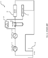
- FIG. 1 depicts a prior art lubrication system.
- oil is pumped from an oil pan 12 by a lube pump 14 to a lube cooler 16.
- the cooled oil is passed through a lube filter 18 and provided to the bearing systems 20 of the engine and the piston cooling nozzles ("PCN") circuit 22.
- PCN piston cooling nozzles
- the oil is returned from bearing systems 20 and PCN circuit 22 to oil pan 12 for reuse.
- the entire flow of oil from oil pan 12 is cooled (by cooler 16) and filtered (by filter 18) before being routed to bearing system 20 and PCN circuit 22.
- the present disclosure provides a lubrication system, comprising: a pump having an inlet in fluid communication with a lubricant source and an outlet; a cooler having an inlet in fluid communication with the outlet of the pump and an outlet; a lubrication filter having an inlet in fluid communication with the outlet of the cooler and an outlet; a first delivery path in fluid communication with the outlet of the lubrication filter, the first delivery path being configured to deliver cooled, filtered lubricant to a bearing system of an engine; and a second delivery path in fluid communication with the outlet of the pump, the second delivery path being configured to deliver uncooled, unfiltered lubricant to piston cooling nozzles of the engine.
- One aspect of this embodiment further comprises a return path in fluid communication with the bearing system and the piston cooling nozzles to return lubricant to the lubricant source. Another aspect further comprises a screen disposed in the second delivery path for inhibiting passage of large particles to the piston cooling nozzles.
- the pump draws an amount of lubricant from the lubrication source and the cooled, filtered lubricant delivered to the bearing system of the engine constitutes about 50% of the amount of lubricant drawn from the lubrication source.
- the present disclosure provides a lubrication system, comprising: a pump having an inlet in fluid communication with a lubricant source and an outlet; a cooler having an inlet in fluid communication with the outlet of the pump and an outlet; a lubrication filter having an inlet in fluid communication with the outlet of the cooler and an outlet; a first delivery path in fluid communication with the outlet of the lubrication filter, the first delivery path being configured to deliver cooled, filtered lubricant to a bearing system of an engine; and a second delivery path in fluid communication with the outlet of the cooler, the second delivery path being configured to deliver cooled, unfiltered lubricant to piston cooling nozzles of the engine.
- One aspect of this embodiment further comprises a return path in fluid communication with the bearing system and the piston cooling nozzles to return lubricant to the lubricant source.
- Another aspect further comprises a screen disposed in the second delivery path for inhibiting passage of large particles to the piston cooling nozzles.
- the present disclosure provides a lubrication system, comprising: a pump having an inlet in fluid communication with a lubricant source and an outlet; a cooler having an inlet in fluid communication with the outlet of the pump and an outlet; a lubrication filter having an inlet in fluid communication with the outlet of the pump and an outlet; a first delivery path in fluid communication with the outlet of the lubrication filter, the first delivery path being configured to deliver uncooled, filtered lubricant to a bearing system of an engine; and a second delivery path in fluid communication with the outlet of the cooler, the second delivery path being configured to deliver cooled, unfiltered lubricant to piston cooling nozzles of the engine.
- a return path in fluid communication with the bearing system and the piston cooling nozzles to return lubricant to the lubricant source.
- Another aspect further comprises a screen disposed in the second delivery.
- a method of providing lubricant to a bearing system of an engine and piston cooling nozzles of the engine comprising: pumping lubricant from a lubricant source to a pump outlet; routing a first portion of the pumped lubricant from the pump outlet to an inlet of a cooler, the cooler having an outlet; routing a second portion of the pumped lubricant from the pump outlet to the piston cooling nozzles; routing lubricant from the cooler outlet to an inlet of a lubrication filter, the lubrication filter having an outlet; and routing lubricant from the lubrication filter outlet to the bearing system.
- One aspect of this embodiment further comprises routing lubricant from the bearing system and the piston cooling nozzles through a return path to the lubricant source.
- routing a second portion of the pumped lubricant includes passing the second portion of the pumped lubricant through a screen to inhibit passage of large particles to the piston cooling nozzles.
- the present disclosure provides a method of providing lubricant to a bearing system of an engine and piston cooling nozzles of the engine, comprising: pumping lubricant from a lubricant source to a pump outlet; routing the pumped lubricant from the pump outlet to an inlet of a cooler, the cooler having an outlet; routing a first portion of lubricant from the cooler outlet to the piston cooling nozzles; routing a second portion of the lubricant from the cooler outlet to an inlet of a lubrication filter, the lubrication filter having an outlet; and routing lubricant from the lubrication filter outlet to the bearing system.
- One aspect of this embodiment further comprises routing lubricant from the bearing system and the piston cooling nozzles through a return path to the lubricant source.
- routing a first portion of the lubricant from the cooler includes passing the first portion of the lubricant through a screen to inhibit passage of large particles to the piston cooling nozzles.
- the present disclosure provides a method of providing lubricant to a bearing system of an engine and piston cooling nozzles of the engine, comprising: pumping lubricant from a lubricant source to a pump outlet; routing a first portion of the pumped lubricant from the pump outlet to an inlet of a cooler, the cooler having an outlet; routing a second portion of the pumped lubricant from the pump outlet to an inlet of a lubrication filter, the lubrication filter having an outlet; routing lubricant from the cooler outlet to the piston cooling nozzles; and routing lubricant from the lubrication filter outlet to the bearing system.
- One aspect of this embodiment further comprises routing lubricant from the bearing system and the piston cooling nozzles through a return path to the lubricant source.
- routing lubricant from the cooler outlet includes passing the lubricant through a screen to inhibit passage of large particles to the piston cooling nozzles.
- the embodiments of the present disclosure provide dedicated circuits or delivery paths for the engine bearing system and the PCN circuit. As such, certain components of the lubrication system are bypassed in a way that reduces the parasitic losses of the system, which thereby improves engine efficiency and fuel consumption.
- System 24 includes the same components as those described above with reference to the prior art system 10.
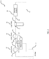
- oil is pumped from oil pan 12 to inlet 27 of lube pump 14. From outlet 29 of lube pump 14, oil is provided directly to PCN circuit 22 via delivery path 31 . It should be understood that oil provided to PCN circuit 22 may be passed through a screen (e.g., a 300 micron screen) to prevent large particles from reaching the piston cooling nozzles. Screen 25 is depicted in dotted lines. Oil is also provided by pump 14 to inlet 33 of lube cooler 16. Cooled oil flows from outlet 35 of cooler 16 to inlet 37 of lube filter 18 before being routed from outlet 39 of lube filter 18 to bearing systems 20 delivery path 41 . Oil is returned from bearing systems 20 and PCN circuit 22 via return path 43 to oil pan 12.
- a screen e.g., a 300 micron screen
- the gerotors or gears (depending on the platform) are adjusted down as required.
- pumping work is reduced, bypass leakage is reduced, implementation is fast, reliability is improved by removing the bypass, and cost is reduced.
- PCN shutoff features may be combined with PCN shutoff features and variable flow pumps to further reduce circuit parasitic power. More specifically, PCN flow may be switched on and off depending on thermal load if a variable flow lube pump is used. This optional "higher complexity" lube circuit control reduces parasitic lube circuit power when piston temperatures permit.
- check valves/solenoid valves may be included in the PCN circuit.
- thermostat(s) may be used in the various circuits and lube pump 14 may be configured as a standard or variable pump.
- System 26 includes the same components as system 24. Accordingly, the same reference designations are used.
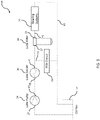
- oil is pumped from oil pan 12 to inlet 27 of pump 14. Oil is pumped from outlet 29 of pump 14 to inlet 33 of cooler 16. Cooled oil is then routed from outlet 35 of cooler 16 to PCN circuit 22 via delivery path 31 and to inlet 37 of filter 18. Cooled, filtered oil is routed from outlet 39 of filter 18 to bearing systems 20 via delivery path 41 . Return oil is routed from bearing systems 20 and PCN circuit 22 to oil pan 12 via return path 43.
- system 26 may also include a screen 25 (as described above with reference to system 24) between cooler 16 and PCN circuit 22 in delivery path 31.
- System 26 thus differs from system 24 in that in system 26, oil is passed through cooler 16 before being routed to PCN circuit 22 whereas in system 24 the oil is provided to PCN circuit 22 directly from pump 14 (i.e., the oil is not passed through cooler 16 before flowing to PCN circuit 22). Thus, in system 26, cooled and unfiltered oil is provided to PCN circuit 22.
- System 28 includes the same components as system 24. Accordingly, the same reference designations are used.
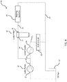
- oil is pumped from oil pan 12 to inlet 27 of pump 14. Oil is pumped from outlet 29 of pump 14 to inlet 33 of cooler 16 and inlet 37 of filter 18. Cooled oil is then routed from outlet 35 of cooler 16 to PCN circuit 22 via delivery path 31. Uncooled, filtered oil is routed from outlet 39 of filter 18 to bearing systems 20 via delivery path 41. Return oil is routed from bearing systems 20 and PCN circuit 22 to oil pan 12 via return path 43.
- system 28 may also include a screen 25 (as described above with reference to system 24) between cooler 16 and PCN circuit 22.
- System 28 thus differs from system 26 in that in system 28, the oil pumped to filter 18 is not passed through cooler 16 whereas in system 26 the oil is cooled before being provided to filter 18 (and bearing systems 20).
- This embodiment provides increased cooling to the piston and rings via the cooled oil flow while delivering higher temperature oil to the bearings which reduces the parasitic power required to rotate the crankshaft and camshaft in their respective bearings.
- the modifier "about” used in connection with a quantity is inclusive of the stated value and has the meaning dictated by the context (for example, it includes at least the degree of error associated with the measurement of the particular quantity).
- the modifier "about” should also be considered as disclosing the range defined by the absolute values of the two endpoints. For example, the range “from about 2 to about 4" also discloses the range “from 2 to 4.”
- references to "one embodiment,” “an embodiment,” “an example embodiment,” etc. indicate that the embodiment described may include a particular feature, structure, or characteristic, but every embodiment may not necessarily include the particular feature, structure, or characteristic. Moreover, such phrases are not necessarily referring to the same embodiment. Further, when a particular feature, structure, or characteristic is described in connection with an embodiment, it is submitted that it is within the knowledge of one skilled in the art with the benefit of the present disclosure to affect such feature, structure, or characteristic in connection with other embodiments whether or not explicitly described. After reading the description, it will be apparent to one skilled in the relevant art(s) how to implement the disclosure in alternative embodiments.
Landscapes
- Engineering & Computer Science (AREA)
- Mechanical Engineering (AREA)
- General Engineering & Computer Science (AREA)
- Lubrication Of Internal Combustion Engines (AREA)
Abstract
Description
- This application claims priority to
U.S. Provisional Application S/N 62/414,997 - The present invention relates generally to engine lubrication systems and more particularly to systems having dedicated lubrication circuits to reduce parasitic power.
- Engine lubrication systems (for diesel, gasoline and/or natural gas engines, and in particular reciprocating piston engines) generally provide a lubricant such as oil to various components of the engine.
FIG. 1 depicts a prior art lubrication system. As shown, oil is pumped from anoil pan 12 by alube pump 14 to alube cooler 16. The cooled oil is passed through alube filter 18 and provided to thebearing systems 20 of the engine and the piston cooling nozzles ("PCN")circuit 22. The oil is returned frombearing systems 20 andPCN circuit 22 tooil pan 12 for reuse. Thus, the entire flow of oil fromoil pan 12 is cooled (by cooler 16) and filtered (by filter 18) before being routed to bearingsystem 20 andPCN circuit 22. Asfilter 18 is a key flow restriction insystem 10, a substantial pressure head is generated forlube pump 14. This pressure head increases the parasitic power required to operate the system, thereby resulting in undesirable fuel consumption. Accordingly, an approach for providing lubricant to engine components that results in reduced parasitic power is needed. SUMMARY - According to one embodiment, the present disclosure provides a lubrication system, comprising: a pump having an inlet in fluid communication with a lubricant source and an outlet; a cooler having an inlet in fluid communication with the outlet of the pump and an outlet; a lubrication filter having an inlet in fluid communication with the outlet of the cooler and an outlet; a first delivery path in fluid communication with the outlet of the lubrication filter, the first delivery path being configured to deliver cooled, filtered lubricant to a bearing system of an engine; and a second delivery path in fluid communication with the outlet of the pump, the second delivery path being configured to deliver uncooled, unfiltered lubricant to piston cooling nozzles of the engine. One aspect of this embodiment further comprises a return path in fluid communication with the bearing system and the piston cooling nozzles to return lubricant to the lubricant source. Another aspect further comprises a screen disposed in the second delivery path for inhibiting passage of large particles to the piston cooling nozzles. In another aspect, the pump draws an amount of lubricant from the lubrication source and the cooled, filtered lubricant delivered to the bearing system of the engine constitutes about 50% of the amount of lubricant drawn from the lubrication source.
- In another embodiment, the present disclosure provides a lubrication system, comprising: a pump having an inlet in fluid communication with a lubricant source and an outlet; a cooler having an inlet in fluid communication with the outlet of the pump and an outlet; a lubrication filter having an inlet in fluid communication with the outlet of the cooler and an outlet; a first delivery path in fluid communication with the outlet of the lubrication filter, the first delivery path being configured to deliver cooled, filtered lubricant to a bearing system of an engine; and a second delivery path in fluid communication with the outlet of the cooler, the second delivery path being configured to deliver cooled, unfiltered lubricant to piston cooling nozzles of the engine. One aspect of this embodiment further comprises a return path in fluid communication with the bearing system and the piston cooling nozzles to return lubricant to the lubricant source. Another aspect further comprises a screen disposed in the second delivery path for inhibiting passage of large particles to the piston cooling nozzles.
- In yet another embodiment, the present disclosure provides a lubrication system, comprising: a pump having an inlet in fluid communication with a lubricant source and an outlet; a cooler having an inlet in fluid communication with the outlet of the pump and an outlet; a lubrication filter having an inlet in fluid communication with the outlet of the pump and an outlet; a first delivery path in fluid communication with the outlet of the lubrication filter, the first delivery path being configured to deliver uncooled, filtered lubricant to a bearing system of an engine; and a second delivery path in fluid communication with the outlet of the cooler, the second delivery path being configured to deliver cooled, unfiltered lubricant to piston cooling nozzles of the engine. One aspect of this embodiment further comprises a return path in fluid communication with the bearing system and the piston cooling nozzles to return lubricant to the lubricant source. Another aspect further comprises a screen disposed in the second delivery.
- In yet another embodiment of the present disclosure, a method of providing lubricant to a bearing system of an engine and piston cooling nozzles of the engine is provided, comprising: pumping lubricant from a lubricant source to a pump outlet; routing a first portion of the pumped lubricant from the pump outlet to an inlet of a cooler, the cooler having an outlet; routing a second portion of the pumped lubricant from the pump outlet to the piston cooling nozzles; routing lubricant from the cooler outlet to an inlet of a lubrication filter, the lubrication filter having an outlet; and routing lubricant from the lubrication filter outlet to the bearing system. One aspect of this embodiment further comprises routing lubricant from the bearing system and the piston cooling nozzles through a return path to the lubricant source. In another aspect, routing a second portion of the pumped lubricant includes passing the second portion of the pumped lubricant through a screen to inhibit passage of large particles to the piston cooling nozzles.
- In still another embodiment, the present disclosure provides a method of providing lubricant to a bearing system of an engine and piston cooling nozzles of the engine, comprising: pumping lubricant from a lubricant source to a pump outlet; routing the pumped lubricant from the pump outlet to an inlet of a cooler, the cooler having an outlet; routing a first portion of lubricant from the cooler outlet to the piston cooling nozzles; routing a second portion of the lubricant from the cooler outlet to an inlet of a lubrication filter, the lubrication filter having an outlet; and routing lubricant from the lubrication filter outlet to the bearing system. One aspect of this embodiment further comprises routing lubricant from the bearing system and the piston cooling nozzles through a return path to the lubricant source. In another aspect, routing a first portion of the lubricant from the cooler includes passing the first portion of the lubricant through a screen to inhibit passage of large particles to the piston cooling nozzles.
- In yet another embodiment, the present disclosure provides a method of providing lubricant to a bearing system of an engine and piston cooling nozzles of the engine, comprising: pumping lubricant from a lubricant source to a pump outlet; routing a first portion of the pumped lubricant from the pump outlet to an inlet of a cooler, the cooler having an outlet; routing a second portion of the pumped lubricant from the pump outlet to an inlet of a lubrication filter, the lubrication filter having an outlet; routing lubricant from the cooler outlet to the piston cooling nozzles; and routing lubricant from the lubrication filter outlet to the bearing system. One aspect of this embodiment further comprises routing lubricant from the bearing system and the piston cooling nozzles through a return path to the lubricant source. In another aspect, routing lubricant from the cooler outlet includes passing the lubricant through a screen to inhibit passage of large particles to the piston cooling nozzles.
- While multiple embodiments are disclosed, still other embodiments of the present invention will become apparent to those skilled in the art from the following detailed description, which shows and describes illustrative embodiments of the invention. Accordingly, the drawings and detailed description are to be regarded as illustrative in nature and not restrictive.
- The above-mentioned and other features of this disclosure and the manner of obtaining them will become more apparent and the disclosure itself will be better understood by reference to the following description of embodiments of the present disclosure taken in conjunction with the accompanying drawings, wherein:
-
FIG. 1 is a schematic diagram of a prior art engine lubrication system; -
FIG. 2 is a schematic diagram of a first embodiment of an engine lubrication system according to the present disclosure; -
FIG. 3 is a schematic diagram of a second embodiment of an engine lubrication system according to the present disclosure; and -
FIG. 4 is a schematic diagram of a third embodiment of an engine lubrication system according to the present disclosure. - While the present disclosure is amenable to various modifications and alternative forms, specific embodiments have been shown by way of example in the drawings and are described in detail below. The present disclosure, however, is not intended to limit the particular embodiments described. On the contrary, the present disclosure is intended to cover all modifications, equivalents, and alternatives falling within the scope of the appended claims.
- As described in detail below, the embodiments of the present disclosure provide dedicated circuits or delivery paths for the engine bearing system and the PCN circuit. As such, certain components of the lubrication system are bypassed in a way that reduces the parasitic losses of the system, which thereby improves engine efficiency and fuel consumption.
- Referring now to
FIG. 2 , a first embodiment of a lubrication system according to the present disclosure is shown.System 24 includes the same components as those described above with reference to theprior art system 10. - Accordingly, the same reference designations are used. As shown, oil is pumped from
oil pan 12 to inlet 27 oflube pump 14. Fromoutlet 29 oflube pump 14, oil is provided directly to PCNcircuit 22 viadelivery path 31 . It should be understood that oil provided toPCN circuit 22 may be passed through a screen (e.g., a 300 micron screen) to prevent large particles from reaching the piston cooling nozzles.Screen 25 is depicted in dotted lines. Oil is also provided bypump 14 to inlet 33 oflube cooler 16. Cooled oil flows fromoutlet 35 ofcooler 16 to inlet 37 oflube filter 18 before being routed fromoutlet 39 oflube filter 18 to bearingsystems 20delivery path 41 . Oil is returned frombearing systems 20 and PCNcircuit 22 viareturn path 43 tooil pan 12. Thus, in this embodiment only a portion (e.g., approximately 50%) of the oil flow is filtered (i.e., the portion provided to bearing systems 20). As such, cooled and filtered oil is only provided to bearingsystem 20 while uncooled and unfiltered oil is provided toPCN circuit 22. This reduction in filtered flow results in an overall reduction in the pressure delta acrosspump 14. Moreover, by employingsystem 24, thefilter bypass system 19 may be removed, reducing the possibility that unfiltered oil may leak into the bearings causing damage. In fact, conventional systems (such as that depicted inFIG. 1 ) contain filters sized for peak flow, but require bypass systems for when the filters become partially clogged. As a result of the embodiment ofFIG. 2 , the previously acceptable filter size is now large enough not to suffer from partial blockage, without a bypass system. - To accommodate the reduced power needs of
system 24, the gerotors or gears (depending on the platform) are adjusted down as required. Thus, pumping work is reduced, bypass leakage is reduced, implementation is fast, reliability is improved by removing the bypass, and cost is reduced. It should further be apparent to those skilled in the art with the benefit of the teachings of the present disclosure that the reduced filtered flow provided bysystem 24 may be combined with PCN shutoff features and variable flow pumps to further reduce circuit parasitic power. More specifically, PCN flow may be switched on and off depending on thermal load if a variable flow lube pump is used. This optional "higher complexity" lube circuit control reduces parasitic lube circuit power when piston temperatures permit. - Finally, it should also be understood that check valves/solenoid valves may be included in the PCN circuit. Moreover, thermostat(s) may be used in the various circuits and
lube pump 14 may be configured as a standard or variable pump. - Referring now to
FIG. 3 , another embodiment of a system according to the present disclosure is shown.System 26 includes the same components assystem 24. Accordingly, the same reference designations are used. Insystem 26, oil is pumped fromoil pan 12 toinlet 27 ofpump 14. Oil is pumped fromoutlet 29 ofpump 14 toinlet 33 of cooler 16. Cooled oil is then routed fromoutlet 35 of cooler 16 toPCN circuit 22 viadelivery path 31 and toinlet 37 offilter 18. Cooled, filtered oil is routed fromoutlet 39 offilter 18 to bearingsystems 20 viadelivery path 41 . Return oil is routed from bearingsystems 20 andPCN circuit 22 tooil pan 12 viareturn path 43. It should be noted thatsystem 26 may also include a screen 25 (as described above with reference to system 24) between cooler 16 andPCN circuit 22 indelivery path 31. -
System 26 thus differs fromsystem 24 in that insystem 26, oil is passed through cooler 16 before being routed toPCN circuit 22 whereas insystem 24 the oil is provided toPCN circuit 22 directly from pump 14 (i.e., the oil is not passed through cooler 16 before flowing to PCN circuit 22). Thus, insystem 26, cooled and unfiltered oil is provided toPCN circuit 22. - Referring now to
FIG. 4 , another embodiment of a system according to the present disclosure is shown.System 28 includes the same components assystem 24. Accordingly, the same reference designations are used. Insystem 28, oil is pumped fromoil pan 12 toinlet 27 ofpump 14. Oil is pumped fromoutlet 29 ofpump 14 toinlet 33 of cooler 16 andinlet 37 offilter 18. Cooled oil is then routed fromoutlet 35 of cooler 16 toPCN circuit 22 viadelivery path 31. Uncooled, filtered oil is routed fromoutlet 39 offilter 18 to bearingsystems 20 viadelivery path 41. Return oil is routed from bearingsystems 20 andPCN circuit 22 tooil pan 12 viareturn path 43. It should be noted thatsystem 28 may also include a screen 25 (as described above with reference to system 24) between cooler 16 andPCN circuit 22. -
System 28 thus differs fromsystem 26 in that insystem 28, the oil pumped to filter 18 is not passed through cooler 16 whereas insystem 26 the oil is cooled before being provided to filter 18 (and bearing systems 20). This embodiment provides increased cooling to the piston and rings via the cooled oil flow while delivering higher temperature oil to the bearings which reduces the parasitic power required to rotate the crankshaft and camshaft in their respective bearings. - As used herein, the modifier "about" used in connection with a quantity is inclusive of the stated value and has the meaning dictated by the context (for example, it includes at least the degree of error associated with the measurement of the particular quantity). When used in the context of a range, the modifier "about" should also be considered as disclosing the range defined by the absolute values of the two endpoints. For example, the range "from about 2 to about 4" also discloses the range "from 2 to 4."
- The connecting lines shown in the various figures contained herein are intended to represent exemplary functional relationships and/or physical couplings between the various elements. It should be noted that many alternative or additional functional relationships or physical connections may be present in a practical system. However, the benefits, advantages, solutions to problems, and any elements that may cause any benefit, advantage, or solution to occur or become more pronounced are not to be construed as critical, required, or essential features or elements. The scope is accordingly to be limited by nothing other than the appended claims, in which reference to an element in the singular is not intended to mean "one and only one" unless explicitly so stated, but rather "one or more." Moreover, where a phrase similar to "at least one of A, B, or C" is used in the claims, it is intended that the phrase be interpreted to mean that A alone may be present in an embodiment, B alone may be present in an embodiment, C alone may be present in an embodiment, or that any combination of the elements A, B or C may be present in a single embodiment; for example, A and B, A and C, B and C, or A and B and C.
- In the detailed description herein, references to "one embodiment," "an embodiment," "an example embodiment," etc., indicate that the embodiment described may include a particular feature, structure, or characteristic, but every embodiment may not necessarily include the particular feature, structure, or characteristic. Moreover, such phrases are not necessarily referring to the same embodiment. Further, when a particular feature, structure, or characteristic is described in connection with an embodiment, it is submitted that it is within the knowledge of one skilled in the art with the benefit of the present disclosure to affect such feature, structure, or characteristic in connection with other embodiments whether or not explicitly described. After reading the description, it will be apparent to one skilled in the relevant art(s) how to implement the disclosure in alternative embodiments.
- Furthermore, no element, component, or method step in the present disclosure is intended to be dedicated to the public regardless of whether the element, component, or method step is explicitly recited in the claims. No claim element herein is to be construed under the provisions of 35 U.S.C. 1 12(f), unless the element is expressly recited using the phrase "means for." As used herein, the terms "comprises," "comprising," or any other variation thereof, are intended to cover a non-exclusive inclusion, such that a process, method, article, or apparatus that comprises a list of elements does not include only those elements but may include other elements not expressly listed or inherent to such process, method, article, or apparatus
- Various modifications and additions can be made to the exemplary embodiments discussed without departing from the scope of the present invention. For example, while the embodiments described above refer to particular features, the scope of this invention also includes embodiments having different combinations of features and embodiments that do not include all of the described features. Accordingly, the scope of the present invention is intended to embrace all such alternatives, modifications, and variations as fall within the scope of the claims, together with all equivalents thereof.
-
- 1 . A lubrication system, comprising:
- a pump having an inlet in fluid communication with a lubricant source and an outlet;
- a cooler having an inlet in fluid communication with the outlet of the pump and an outlet;
- a lubrication filter having an inlet in fluid communication with the outlet of the cooler and
- an outlet;
- a first delivery path in fluid communication with the outlet of the lubrication filter, the first delivery path being configured to deliver cooled, filtered lubricant to a bearing system of an engine; and
- a second delivery path in fluid communication with the outlet of the pump, the second delivery path being configured to deliver uncooled, unfiltered lubricant to piston cooling nozzles of the engine.
- 2. The lubrication system of clause 1 , further comprising a return path in fluid communication with the bearing system and the piston cooling nozzles to return lubricant to the lubricant source.
- 3. The lubrication system of clause 1 , further comprising a screen disposed in the second delivery path for inhibiting passage of large particles to the piston cooling nozzles.
- 4. The lubrication system of clause 1 , wherein the pump draws an amount of lubricant from the lubrication source and the cooled, filtered lubricant delivered to the bearing system of the engine constitutes about 50% of the amount of lubricant drawn from the lubrication source.
- 5. A lubrication system, comprising: a pump having an inlet in fluid communication with a lubricant source and an outlet;
- a cooler having an inlet in fluid communication with the outlet of the pump and an outlet;
- a lubrication filter having an inlet in fluid communication with the outlet of the cooler and an outlet;
- a first delivery path in fluid communication with the outlet of the lubrication filter, the first delivery path being configured to deliver cooled, filtered lubricant to a bearing system of an engine; and
- a second delivery path in fluid communication with the outlet of the cooler, the second delivery path being configured to deliver cooled, unfiltered lubricant to piston cooling nozzles of the engine.
- 6. The lubrication system of clause 5, further comprising a return path in fluid communication with the bearing system and the piston cooling nozzles to return lubricant to the lubricant source.
- 7. The lubrication system of clause 5, further comprising a screen disposed in the second delivery path for inhibiting passage of large particles to the piston cooling nozzles.
- 8. A lubrication system, comprising:
- a pump having an inlet in fluid communication with a lubricant source and an outlet;
- a cooler having an inlet in fluid communication with the outlet of the pump and an outlet;
- a lubrication filter having an inlet in fluid communication with the outlet of the pump and an outlet;
- a first delivery path in fluid communication with the outlet of the lubrication filter, the first delivery path being configured to deliver uncooled, filtered lubricant to a bearing system of an engine; and a second delivery path in fluid communication with the outlet of the cooler, the second delivery path being configured to deliver cooled, unfiltered lubricant to piston cooling nozzles of the engine.
- 9. The lubrication system of clause 8, further comprising a return path in fluid communication with the bearing system and the piston cooling nozzles to return lubricant to the lubricant source.
- 10. The lubrication system of clause 8, further comprising a screen disposed in the second delivery path for inhibiting passage of large particles to the piston cooling nozzles.
- 11. A method of providing lubricant to a bearing system of an engine and piston cooling nozzles of the engine, comprising:
- pumping lubricant from a lubricant source to a pump outlet;
- routing a first portion of the pumped lubricant from the pump outlet to an inlet of a cooler,
- the cooler having an outlet;
- routing a second portion of the pumped lubricant from the pump outlet to the piston cooling nozzles;
- routing lubricant from the cooler outlet to an inlet of a lubrication filter, the lubrication filter having an outlet; and
- routing lubricant from the lubrication filter outlet to the bearing system.
- 12. The method of clause 11, further comprising routing lubricant from the bearing system and the piston cooling nozzles through a return path to the lubricant source.
- 13. The method of clause 11, wherein routing a second portion of the pumped lubricant includes passing the second portion of the pumped lubricant through a screen to inhibit passage of large particles to the piston cooling nozzles.
- 14. A method of providing lubricant to a bearing system of an engine and piston cooling nozzles of the engine, comprising:
- pumping lubricant from a lubricant source to a pump outlet;
- routing the pumped lubricant from the pump outlet to an inlet of a cooler, the cooler having an outlet;
- routing a first portion of lubricant from the cooler outlet to the piston cooling nozzles;
- routing a second portion of the lubricant from the cooler outlet to an inlet of a lubrication filter, the lubrication filter having an outlet; and
- routing lubricant from the lubrication filter outlet to the bearing system.
- 15. The method of
clause 14, further comprising routing lubricant from the bearing system and the piston cooling nozzles through a return path to the lubricant source. - 16. The method of
clause 14, wherein routing a first portion of the lubricant from the cooler includes passing the first portion of the lubricant through a screen to inhibit passage of large particles to the piston cooling nozzles. - 17. A method of providing lubricant to a bearing system of an engine and piston cooling nozzles of the engine, comprising:
- pumping lubricant from a lubricant source to a pump outlet;
- routing a first portion of the pumped lubricant from the pump outlet to an inlet of a cooler, the cooler having an outlet;
- routing a second portion of the pumped lubricant from the pump outlet to an inlet of a lubrication filter, the lubrication filter having an outlet;
- routing lubricant from the cooler outlet to the piston cooling nozzles; and routing lubricant from the lubrication filter outlet to the bearing system.
- 18. The method of clause 17, further comprising routing lubricant from the bearing system and the piston cooling nozzles through a return path to the lubricant source.
- 19. The method of clause 17, wherein routing lubricant from the cooler outlet includes passing the lubricant through a screen to inhibit passage of large particles to the piston cooling nozzles.
Claims (15)
- A lubrication system, comprising:a pump (14) having an inlet (27) in fluid communication with a lubricant source (12) and an outlet (29);a cooler (16) having an inlet (33) in fluid communication with the outlet (29) of the pump (14) and an outlet (35);a lubrication filter (18) having an inlet (37) in fluid communication with the outlet (35) of the cooler (16) and an outlet (39);a first delivery path (41) in fluid communication with the outlet (39) of the lubrication filter (18), the first delivery path (41) being configured to deliver cooled, filtered lubricant to a bearing system (20) of an engine; anda second delivery path (31) in fluid communication with the outlet (35) of the cooler (16), the second delivery path (31) being configured to deliver cooled, unfiltered lubricant to piston cooling nozzles (22) of the engine.
- The lubrication system of claim 1, further comprising a return path (43) in fluid communication with the bearing system (20) and the piston cooling nozzles (22) to return lubricant to the lubricant source (12).
- The lubrication system of claim 1 or 2, further comprising a screen (25) disposed in the second delivery path (31) for inhibiting passage of large particles to the piston cooling nozzles (22).
- The lubrication system of claim 3, wherein the screen (25) is sized to incur partial blockage without a bypass system.
- The lubrication system of claim 4, wherein the screen (25) is a 300-micron screen.
- The lubrication system of claim 1 or 2, wherein the pump (14) is a variable flow pump and further comprising a piston cooling nozzle shut off feature that regulates flow through the piston cooling nozzle.
- The lubrication system of claim 6, wherein the piston cooling nozzle shut off feature is configured to be switched on and off depending on thermal load.
- A method of providing lubricant to a bearing system (20) of an engine and piston cooling nozzles (22) of the engine, comprising:pumping lubricant from a lubricant source (12) to a pump outlet (29);routing first and second portions of the pumped lubricant from the pump outlet (29) to an inlet (33) of a cooler (16), the cooler (16) having an outlet (35);routing the first portion of lubricant from the cooler outlet (35) to the piston cooling nozzles (22);routing the second portion of the pumped lubricant from the cooler outlet (35) to the bearing system (20).
- The method of claim 8, further comprising routing lubricant from the bearing system (20) and the piston cooling nozzles (22) through a return path (43) to the lubricant source (12).
- The method of claim 8 or 9, wherein routing the first portion of the lubricant from the cooler outlet (35) to the piston cooling nozzles (22) includes passing the first portion of the lubricant through a screen (25) to inhibit passage of large particles to the piston cooling nozzles (22).
- The method of claim 8 or 9, wherein routing the first portion of lubricant from the cooler outlet (35) to the piston cooling nozzles (22) includes routing the first portion of the lubricant through a filter (18).
- The method of claim 11, wherein the screen (25) is sized to incur partial blockage without a bypass system.
- The method of claim 11, wherein the screen (25) is a 300-micron screen.
- The method of claim 8 or 9, further comprising routing the second portion of the pumped lubricant from the cooler outlet (35) to an inlet (37) of a lubrication filter (18) that has an outlet (39).
- The method of claim 14, further comprising routing the second portion of the pumped lubricant from the lubrication filter outlet (39) the bearing system (20).
Applications Claiming Priority (3)
| Application Number | Priority Date | Filing Date | Title |
|---|---|---|---|
| US201662414997P | 2016-10-31 | 2016-10-31 | |
| EP17864135.3A EP3516180B1 (en) | 2016-10-31 | 2017-10-31 | Reduced parasitic lube system |
| PCT/US2017/059298 WO2018081800A1 (en) | 2016-10-31 | 2017-10-31 | Reduced parasitic lube system |
Related Parent Applications (1)
| Application Number | Title | Priority Date | Filing Date |
|---|---|---|---|
| EP17864135.3A Division EP3516180B1 (en) | 2016-10-31 | 2017-10-31 | Reduced parasitic lube system |
Publications (1)
| Publication Number | Publication Date |
|---|---|
| EP4098849A1 true EP4098849A1 (en) | 2022-12-07 |
Family
ID=62024099
Family Applications (2)
| Application Number | Title | Priority Date | Filing Date |
|---|---|---|---|
| EP17864135.3A Active EP3516180B1 (en) | 2016-10-31 | 2017-10-31 | Reduced parasitic lube system |
| EP22186272.5A Pending EP4098849A1 (en) | 2016-10-31 | 2017-10-31 | Reduced parasitic lube system |
Family Applications Before (1)
| Application Number | Title | Priority Date | Filing Date |
|---|---|---|---|
| EP17864135.3A Active EP3516180B1 (en) | 2016-10-31 | 2017-10-31 | Reduced parasitic lube system |
Country Status (5)
| Country | Link |
|---|---|
| US (3) | US11719139B2 (en) |
| EP (2) | EP3516180B1 (en) |
| CN (1) | CN110268142B (en) |
| BR (1) | BR112019008815B1 (en) |
| WO (1) | WO2018081800A1 (en) |
Families Citing this family (3)
| Publication number | Priority date | Publication date | Assignee | Title |
|---|---|---|---|---|
| EP3516180B1 (en) * | 2016-10-31 | 2022-08-17 | Cummins Inc. | Reduced parasitic lube system |
| US11732646B2 (en) * | 2021-07-06 | 2023-08-22 | Pratt & Whitney Canada Corp. | Lubrication system for a turbine engine |
| DE102024002795A1 (en) * | 2024-08-29 | 2026-03-05 | Hydac Filtertechnik Gmbh | Fluid supply system |
Citations (6)
| Publication number | Priority date | Publication date | Assignee | Title |
|---|---|---|---|---|
| US3065743A (en) * | 1961-02-09 | 1962-11-27 | Int Harvester Co | Internal combustion engine lubricating system and temperature regulating means for the pistons thereof |
| US3485324A (en) * | 1967-11-07 | 1969-12-23 | Allis Chalmers Mfg Co | Piston cooling system |
| DD97262A1 (en) * | 1972-06-06 | 1973-04-20 | ||
| US4058981A (en) * | 1976-06-04 | 1977-11-22 | Caterpillar Tractor Co. | Lubricating system and method for turbocharged engines |
| JPS58149506U (en) * | 1982-03-31 | 1983-10-07 | 三菱自動車工業株式会社 | engine cooling system |
| DE102008032496A1 (en) * | 2008-07-05 | 2010-01-07 | Daimler Ag | Lubricant i.e. oil, supply system for petrol engine in motor vehicle, has pipeline arranged downstream to two valve devices and deviating from piston lubrication/cooling system, where third valve device is arranged in pipeline |
Family Cites Families (34)
| Publication number | Priority date | Publication date | Assignee | Title |
|---|---|---|---|---|
| DE97262C (en) | ||||
| US3090365A (en) * | 1960-07-06 | 1963-05-21 | Curtiss Wright Corp | Engine lubrication and cooling system |
| DE1476088A1 (en) * | 1965-04-10 | 1969-03-27 | Opel Adam Ag | Arrangement of regulating and control organs in a lubricating oil circuit |
| US3453995A (en) * | 1965-06-11 | 1969-07-08 | Mack Trucks | Piston cooling and lubrication system |
| DE2123011A1 (en) * | 1971-05-10 | 1972-12-14 | Audi NSU Auto Union AG, 7107 Neckars ulm, Wankel GmbH, 8990 Lindau | Rotary piston internal combustion engine with oil-cooled piston |
| US3741342A (en) * | 1971-11-08 | 1973-06-26 | Int Harvester Co | Engine oil cooling and filtering method and apparatus |
| DE2546273C2 (en) * | 1975-10-16 | 1984-11-22 | Audi Nsu Auto Union Ag, 7107 Neckarsulm | Device for regulating piston oil cooling for a piston internal combustion engine |
| GB1567240A (en) * | 1977-04-28 | 1980-05-14 | Brown Tractors Ltd | Internal combustion engines |
| JPS58131304A (en) * | 1982-01-29 | 1983-08-05 | Toyota Motor Corp | Oil cooling system of vehicle equipped with turbosupercharger |
| US4512299A (en) * | 1983-12-12 | 1985-04-23 | International Harvester Company | Automotive engine with improved multifilter lubrication system |
| DE4430751A1 (en) * | 1994-08-30 | 1996-03-07 | Mann & Hummel Filter | Fluid circuit with a main flow filter |
| EP1381441A4 (en) * | 2001-04-26 | 2005-01-26 | Engineered Machined Products I | AUXILIARY FILTERING SYSTEM AND ASSOCIATED METHOD |
| GB2388634A (en) * | 2002-05-15 | 2003-11-19 | Dana Automotive Ltd | Engine lubrication system having dual/auxiliary pump operation |
| US20050120982A1 (en) * | 2003-12-09 | 2005-06-09 | Detroit Diesel Corporation | Separate oil gallery for piston cooling with electronic oil flow control |
| DE102005012073A1 (en) * | 2005-03-16 | 2006-09-28 | Dr.Ing.H.C. F. Porsche Ag | Lubricating oil supply device for an internal combustion engine |
| CN201152182Y (en) * | 2007-11-16 | 2008-11-19 | 中国神华能源股份有限公司 | Internal-combustion engines engine oil path system |
| DE102010019007A1 (en) * | 2010-05-03 | 2011-11-03 | Gm Global Technology Operations Llc (N.D.Ges.D. Staates Delaware) | Lubricating circuit |
| DE102010023063B4 (en) * | 2010-06-08 | 2022-05-19 | Dr. Ing. H.C. F. Porsche Aktiengesellschaft | Oil supply system for an internal combustion engine |
| US8945400B2 (en) * | 2010-09-30 | 2015-02-03 | Pareto Point Industries, Inc. | Method and apparatus for a parallel bypass filtration system for internal combustion engines and similar systems |
| DE102011084597A1 (en) * | 2011-10-17 | 2013-04-18 | Ford Global Technologies, Llc | Internal combustion engine with oil circuit and method for producing such an internal combustion engine |
| US8387571B2 (en) * | 2011-11-04 | 2013-03-05 | Ford Global Technologies, Llc | Oil delivery system |
| KR101262274B1 (en) * | 2011-11-16 | 2013-05-08 | 현대자동차주식회사 | Engine oil circulation apparatus for vehicle |
| EP2918799B1 (en) * | 2012-11-07 | 2019-04-17 | Nissan Motor Company, Limited | Oil supply device for internal combustion engine |
| BR102013017090A2 (en) * | 2013-07-02 | 2015-06-30 | Mahle Metal Leve Sa | Heat exchanger for fuel supply in internal combustion engines |
| BR102013017086B1 (en) * | 2013-07-02 | 2020-11-24 | Mahle Metal Leve S/A | HEAT EXCHANGER FOR THERMAL MANAGEMENT SYSTEMS FOR FUEL SUPPLY IN INTERNAL COMBUSTION ENGINES |
| US9644506B2 (en) * | 2014-03-25 | 2017-05-09 | Ford Global Technologies, Llc | Method and system of oil delivery in a combustion engine |
| US10066507B1 (en) * | 2015-02-10 | 2018-09-04 | United Technologies Corporation | Turbine engine lubrication system with wash flow filter |
| ITUB20153993A1 (en) | 2015-09-29 | 2017-03-29 | Fpt Motorenforschung Ag | LUBRICATION OIL CIRCUIT AND COOLING OF AN INTERNAL COMBUSTION ENGINE |
| CN205025524U (en) * | 2015-09-30 | 2016-02-10 | 北汽福田汽车股份有限公司 | Engine lubrication system , engine and vehicle |
| EP3516180B1 (en) * | 2016-10-31 | 2022-08-17 | Cummins Inc. | Reduced parasitic lube system |
| GB201804506D0 (en) * | 2018-03-21 | 2018-05-02 | Rolls Royce Plc | Oil system |
| WO2021026209A1 (en) * | 2019-08-08 | 2021-02-11 | Cummins Inc. | Passive piston cooling nozzle control with low speed hot running protection |
| CN116034220A (en) * | 2020-02-21 | 2023-04-28 | 卡明斯公司 | Maintains oil pressure during cylinder deactivation operation |
| US11466600B1 (en) * | 2021-03-16 | 2022-10-11 | Cummins Inc. | Lubrication fluid filter bypass system |
-
2017
- 2017-10-31 EP EP17864135.3A patent/EP3516180B1/en active Active
- 2017-10-31 WO PCT/US2017/059298 patent/WO2018081800A1/en not_active Ceased
- 2017-10-31 CN CN201780064990.7A patent/CN110268142B/en active Active
- 2017-10-31 EP EP22186272.5A patent/EP4098849A1/en active Pending
- 2017-10-31 BR BR112019008815-6A patent/BR112019008815B1/en active IP Right Grant
- 2017-10-31 US US16/346,403 patent/US11719139B2/en active Active
-
2023
- 2023-06-21 US US18/212,657 patent/US12163449B2/en active Active
-
2024
- 2024-11-07 US US18/940,402 patent/US20250067199A1/en active Pending
Patent Citations (6)
| Publication number | Priority date | Publication date | Assignee | Title |
|---|---|---|---|---|
| US3065743A (en) * | 1961-02-09 | 1962-11-27 | Int Harvester Co | Internal combustion engine lubricating system and temperature regulating means for the pistons thereof |
| US3485324A (en) * | 1967-11-07 | 1969-12-23 | Allis Chalmers Mfg Co | Piston cooling system |
| DD97262A1 (en) * | 1972-06-06 | 1973-04-20 | ||
| US4058981A (en) * | 1976-06-04 | 1977-11-22 | Caterpillar Tractor Co. | Lubricating system and method for turbocharged engines |
| JPS58149506U (en) * | 1982-03-31 | 1983-10-07 | 三菱自動車工業株式会社 | engine cooling system |
| DE102008032496A1 (en) * | 2008-07-05 | 2010-01-07 | Daimler Ag | Lubricant i.e. oil, supply system for petrol engine in motor vehicle, has pipeline arranged downstream to two valve devices and deviating from piston lubrication/cooling system, where third valve device is arranged in pipeline |
Also Published As
| Publication number | Publication date |
|---|---|
| BR112019008815A2 (en) | 2019-07-16 |
| US20230332521A1 (en) | 2023-10-19 |
| CN110268142B (en) | 2021-05-25 |
| US20250067199A1 (en) | 2025-02-27 |
| EP3516180B1 (en) | 2022-08-17 |
| US11719139B2 (en) | 2023-08-08 |
| WO2018081800A1 (en) | 2018-05-03 |
| US12163449B2 (en) | 2024-12-10 |
| US20190271241A1 (en) | 2019-09-05 |
| EP3516180A1 (en) | 2019-07-31 |
| CN110268142A (en) | 2019-09-20 |
| BR112019008815B1 (en) | 2023-05-02 |
| EP3516180A4 (en) | 2020-06-17 |
Similar Documents
| Publication | Publication Date | Title |
|---|---|---|
| US12163449B2 (en) | Reduced parasitic lube system | |
| US7509793B2 (en) | Fluid system | |
| JP4195308B2 (en) | Fluid flow system for gas turbine engine | |
| EP3257744B1 (en) | Propeller blade angle control system | |
| US10247102B2 (en) | Fuel/oil manifold | |
| US10865713B2 (en) | Systems and methods for cooling electronic engine control devices | |
| EP3495640B1 (en) | Hydraulic and pneumatic control circuit for turbojet with fuel/air heat exchanger | |
| JP2008544139A (en) | Fuel injection system used in internal combustion engines | |
| US20080314572A1 (en) | Lubrication system and oil cooler with bypass | |
| JP5897602B2 (en) | Method and apparatus for supplying lubricant | |
| CN116529470A (en) | Aircraft turbine engine assembly comprising a passive valve for bypassing a fuel/oil heat exchanger | |
| CN109707482A (en) | Engine pre-lubrication system | |
| CA3166700A1 (en) | Lubrication system for a turbine engine | |
| US11719128B2 (en) | Lubrication system with anti-priming feature | |
| US20250297574A1 (en) | Fuel system with fuel cooled electric generation and fuel oil cooler elimination | |
| CN107869369B (en) | Fluid monitoring system on engine | |
| US10920628B2 (en) | Cooling assembly for a filter head of an engine | |
| CN106321187A (en) | Engine, engine lubricating system and engine lubricating method | |
| US20160108876A1 (en) | Oil filter | |
| US10253693B2 (en) | Thermal management system manifold | |
| EP2913496B1 (en) | Integrated thermostatic valve and charge air cooler cover assembly | |
| CN117062970A (en) | Lubricating fluid filter bypass system | |
| US12492662B2 (en) | Fuel pump with built-in thermal bypass | |
| CN112240236A (en) | System and method for piston cooling nozzle control | |
| CN211598776U (en) | Oil supply system |
Legal Events
| Date | Code | Title | Description |
|---|---|---|---|
| PUAI | Public reference made under article 153(3) epc to a published international application that has entered the european phase |
Free format text: ORIGINAL CODE: 0009012 |
|
| STAA | Information on the status of an ep patent application or granted ep patent |
Free format text: STATUS: THE APPLICATION HAS BEEN PUBLISHED |
|
| AC | Divisional application: reference to earlier application |
Ref document number: 3516180 Country of ref document: EP Kind code of ref document: P |
|
| AK | Designated contracting states |
Kind code of ref document: A1 Designated state(s): AL AT BE BG CH CY CZ DE DK EE ES FI FR GB GR HR HU IE IS IT LI LT LU LV MC MK MT NL NO PL PT RO RS SE SI SK SM TR |
|
| STAA | Information on the status of an ep patent application or granted ep patent |
Free format text: STATUS: REQUEST FOR EXAMINATION WAS MADE |
|
| 17P | Request for examination filed |
Effective date: 20230607 |
|
| RBV | Designated contracting states (corrected) |
Designated state(s): AL AT BE BG CH CY CZ DE DK EE ES FI FR GB GR HR HU IE IS IT LI LT LU LV MC MK MT NL NO PL PT RO RS SE SI SK SM TR |
|
| STAA | Information on the status of an ep patent application or granted ep patent |
Free format text: STATUS: EXAMINATION IS IN PROGRESS |
|
| 17Q | First examination report despatched |
Effective date: 20230901 |
|
| GRAP | Despatch of communication of intention to grant a patent |
Free format text: ORIGINAL CODE: EPIDOSNIGR1 |
|
| STAA | Information on the status of an ep patent application or granted ep patent |
Free format text: STATUS: GRANT OF PATENT IS INTENDED |
|
| INTG | Intention to grant announced |
Effective date: 20251219 |
|
| GRAS | Grant fee paid |
Free format text: ORIGINAL CODE: EPIDOSNIGR3 |
|
| GRAA | (expected) grant |
Free format text: ORIGINAL CODE: 0009210 |
|
| STAA | Information on the status of an ep patent application or granted ep patent |
Free format text: STATUS: THE PATENT HAS BEEN GRANTED |