EP4098493A1 - Control device and vehicle power distribution architecture incorporating the same - Google Patents
Control device and vehicle power distribution architecture incorporating the same Download PDFInfo
- Publication number
- EP4098493A1 EP4098493A1 EP21177800.6A EP21177800A EP4098493A1 EP 4098493 A1 EP4098493 A1 EP 4098493A1 EP 21177800 A EP21177800 A EP 21177800A EP 4098493 A1 EP4098493 A1 EP 4098493A1
- Authority
- EP
- European Patent Office
- Prior art keywords
- current
- voltage
- control device
- threshold
- level input
- Prior art date
- Legal status (The legal status is an assumption and is not a legal conclusion. Google has not performed a legal analysis and makes no representation as to the accuracy of the status listed.)
- Granted
Links
Images


Classifications
-
- B—PERFORMING OPERATIONS; TRANSPORTING
- B60—VEHICLES IN GENERAL
- B60R—VEHICLES, VEHICLE FITTINGS, OR VEHICLE PARTS, NOT OTHERWISE PROVIDED FOR
- B60R16/00—Electric or fluid circuits specially adapted for vehicles and not otherwise provided for; Arrangement of elements of electric or fluid circuits specially adapted for vehicles and not otherwise provided for
- B60R16/02—Electric or fluid circuits specially adapted for vehicles and not otherwise provided for; Arrangement of elements of electric or fluid circuits specially adapted for vehicles and not otherwise provided for electric constitutive elements
- B60R16/03—Electric or fluid circuits specially adapted for vehicles and not otherwise provided for; Arrangement of elements of electric or fluid circuits specially adapted for vehicles and not otherwise provided for electric constitutive elements for supply of electrical power to vehicle subsystems or for
-
- H—ELECTRICITY
- H02—GENERATION; CONVERSION OR DISTRIBUTION OF ELECTRIC POWER
- H02J—ELECTRIC POWER NETWORKS; CIRCUIT ARRANGEMENTS OR SYSTEMS FOR SUPPLYING OR DISTRIBUTING ELECTRIC POWER; SYSTEMS FOR STORING ELECTRIC ENERGY
- H02J7/00—Circuit arrangements for charging or discharging batteries or for supplying loads from batteries
- H02J7/40—Circuit arrangements for charging or discharging batteries or for supplying loads from batteries characterised by the exchange of charge or discharge related data
-
- B—PERFORMING OPERATIONS; TRANSPORTING
- B60—VEHICLES IN GENERAL
- B60L—PROPULSION OF ELECTRICALLY-PROPELLED VEHICLES; SUPPLYING ELECTRIC POWER FOR AUXILIARY EQUIPMENT OF ELECTRICALLY-PROPELLED VEHICLES; ELECTRODYNAMIC BRAKE SYSTEMS FOR VEHICLES IN GENERAL; MAGNETIC SUSPENSION OR LEVITATION FOR VEHICLES; MONITORING OPERATING VARIABLES OF ELECTRICALLY-PROPELLED VEHICLES; ELECTRIC SAFETY DEVICES FOR ELECTRICALLY-PROPELLED VEHICLES
- B60L58/00—Methods or circuit arrangements for monitoring or controlling batteries or fuel cells, specially adapted for electric vehicles
- B60L58/10—Methods or circuit arrangements for monitoring or controlling batteries or fuel cells, specially adapted for electric vehicles for monitoring or controlling batteries
-
- H—ELECTRICITY
- H02—GENERATION; CONVERSION OR DISTRIBUTION OF ELECTRIC POWER
- H02J—ELECTRIC POWER NETWORKS; CIRCUIT ARRANGEMENTS OR SYSTEMS FOR SUPPLYING OR DISTRIBUTING ELECTRIC POWER; SYSTEMS FOR STORING ELECTRIC ENERGY
- H02J1/00—Circuit arrangements for DC mains or DC distribution networks
- H02J1/06—Two-wire DC power distribution systems
-
- H—ELECTRICITY
- H02—GENERATION; CONVERSION OR DISTRIBUTION OF ELECTRIC POWER
- H02J—ELECTRIC POWER NETWORKS; CIRCUIT ARRANGEMENTS OR SYSTEMS FOR SUPPLYING OR DISTRIBUTING ELECTRIC POWER; SYSTEMS FOR STORING ELECTRIC ENERGY
- H02J1/00—Circuit arrangements for DC mains or DC distribution networks
- H02J1/10—Parallel operation of DC sources
- H02J1/108—Parallel operation of DC sources having arrangements for blocking reverse current flow, e.g. using diodes
-
- H—ELECTRICITY
- H02—GENERATION; CONVERSION OR DISTRIBUTION OF ELECTRIC POWER
- H02J—ELECTRIC POWER NETWORKS; CIRCUIT ARRANGEMENTS OR SYSTEMS FOR SUPPLYING OR DISTRIBUTING ELECTRIC POWER; SYSTEMS FOR STORING ELECTRIC ENERGY
- H02J13/00—Circuit arrangements for providing remote monitoring or remote control of equipment in a power distribution network
- H02J13/12—Monitoring network conditions, e.g. electrical magnitudes or operational status
-
- H—ELECTRICITY
- H02—GENERATION; CONVERSION OR DISTRIBUTION OF ELECTRIC POWER
- H02J—ELECTRIC POWER NETWORKS; CIRCUIT ARRANGEMENTS OR SYSTEMS FOR SUPPLYING OR DISTRIBUTING ELECTRIC POWER; SYSTEMS FOR STORING ELECTRIC ENERGY
- H02J7/00—Circuit arrangements for charging or discharging batteries or for supplying loads from batteries
- H02J7/14—Circuit arrangements for charging or discharging batteries or for supplying loads from batteries for charging batteries from dynamo-electric generators driven at varying speed, e.g. on vehicle
- H02J7/1423—Circuit arrangements for charging or discharging batteries or for supplying loads from batteries for charging batteries from dynamo-electric generators driven at varying speed, e.g. on vehicle with multiple batteries
-
- H—ELECTRICITY
- H02—GENERATION; CONVERSION OR DISTRIBUTION OF ELECTRIC POWER
- H02J—ELECTRIC POWER NETWORKS; CIRCUIT ARRANGEMENTS OR SYSTEMS FOR SUPPLYING OR DISTRIBUTING ELECTRIC POWER; SYSTEMS FOR STORING ELECTRIC ENERGY
- H02J7/00—Circuit arrangements for charging or discharging batteries or for supplying loads from batteries
- H02J7/60—Circuit arrangements for charging or discharging batteries or for supplying loads from batteries including safety or protection arrangements
- H02J7/62—Circuit arrangements for charging or discharging batteries or for supplying loads from batteries including safety or protection arrangements against overcurrent
-
- H—ELECTRICITY
- H02—GENERATION; CONVERSION OR DISTRIBUTION OF ELECTRIC POWER
- H02J—ELECTRIC POWER NETWORKS; CIRCUIT ARRANGEMENTS OR SYSTEMS FOR SUPPLYING OR DISTRIBUTING ELECTRIC POWER; SYSTEMS FOR STORING ELECTRIC ENERGY
- H02J7/00—Circuit arrangements for charging or discharging batteries or for supplying loads from batteries
- H02J7/60—Circuit arrangements for charging or discharging batteries or for supplying loads from batteries including safety or protection arrangements
- H02J7/64—Circuit arrangements for charging or discharging batteries or for supplying loads from batteries including safety or protection arrangements against overvoltage
-
- H—ELECTRICITY
- H02—GENERATION; CONVERSION OR DISTRIBUTION OF ELECTRIC POWER
- H02J—ELECTRIC POWER NETWORKS; CIRCUIT ARRANGEMENTS OR SYSTEMS FOR SUPPLYING OR DISTRIBUTING ELECTRIC POWER; SYSTEMS FOR STORING ELECTRIC ENERGY
- H02J7/00—Circuit arrangements for charging or discharging batteries or for supplying loads from batteries
- H02J7/60—Circuit arrangements for charging or discharging batteries or for supplying loads from batteries including safety or protection arrangements
- H02J7/663—Circuit arrangements for charging or discharging batteries or for supplying loads from batteries including safety or protection arrangements using battery or load disconnect circuits
-
- H—ELECTRICITY
- H02—GENERATION; CONVERSION OR DISTRIBUTION OF ELECTRIC POWER
- H02J—ELECTRIC POWER NETWORKS; CIRCUIT ARRANGEMENTS OR SYSTEMS FOR SUPPLYING OR DISTRIBUTING ELECTRIC POWER; SYSTEMS FOR STORING ELECTRIC ENERGY
- H02J7/00—Circuit arrangements for charging or discharging batteries or for supplying loads from batteries
- H02J7/80—Circuit arrangements for charging or discharging batteries or for supplying loads from batteries including monitoring or indicating arrangements
-
- B—PERFORMING OPERATIONS; TRANSPORTING
- B60—VEHICLES IN GENERAL
- B60L—PROPULSION OF ELECTRICALLY-PROPELLED VEHICLES; SUPPLYING ELECTRIC POWER FOR AUXILIARY EQUIPMENT OF ELECTRICALLY-PROPELLED VEHICLES; ELECTRODYNAMIC BRAKE SYSTEMS FOR VEHICLES IN GENERAL; MAGNETIC SUSPENSION OR LEVITATION FOR VEHICLES; MONITORING OPERATING VARIABLES OF ELECTRICALLY-PROPELLED VEHICLES; ELECTRIC SAFETY DEVICES FOR ELECTRICALLY-PROPELLED VEHICLES
- B60L2240/00—Control parameters of input or output; Target parameters
- B60L2240/40—Drive Train control parameters
- B60L2240/54—Drive Train control parameters related to batteries
- B60L2240/547—Voltage
-
- B—PERFORMING OPERATIONS; TRANSPORTING
- B60—VEHICLES IN GENERAL
- B60L—PROPULSION OF ELECTRICALLY-PROPELLED VEHICLES; SUPPLYING ELECTRIC POWER FOR AUXILIARY EQUIPMENT OF ELECTRICALLY-PROPELLED VEHICLES; ELECTRODYNAMIC BRAKE SYSTEMS FOR VEHICLES IN GENERAL; MAGNETIC SUSPENSION OR LEVITATION FOR VEHICLES; MONITORING OPERATING VARIABLES OF ELECTRICALLY-PROPELLED VEHICLES; ELECTRIC SAFETY DEVICES FOR ELECTRICALLY-PROPELLED VEHICLES
- B60L2240/00—Control parameters of input or output; Target parameters
- B60L2240/40—Drive Train control parameters
- B60L2240/54—Drive Train control parameters related to batteries
- B60L2240/549—Current
-
- H—ELECTRICITY
- H02—GENERATION; CONVERSION OR DISTRIBUTION OF ELECTRIC POWER
- H02J—ELECTRIC POWER NETWORKS; CIRCUIT ARRANGEMENTS OR SYSTEMS FOR SUPPLYING OR DISTRIBUTING ELECTRIC POWER; SYSTEMS FOR STORING ELECTRIC ENERGY
- H02J2105/00—Networks for supplying or distributing electric power characterised by their spatial reach or by the load
- H02J2105/30—Networks for supplying or distributing electric power characterised by their spatial reach or by the load the load networks being external to vehicles, i.e. exchanging power with vehicles
- H02J2105/33—Networks for supplying or distributing electric power characterised by their spatial reach or by the load the load networks being external to vehicles, i.e. exchanging power with vehicles exchanging power with road vehicles
-
- Y—GENERAL TAGGING OF NEW TECHNOLOGICAL DEVELOPMENTS; GENERAL TAGGING OF CROSS-SECTIONAL TECHNOLOGIES SPANNING OVER SEVERAL SECTIONS OF THE IPC; TECHNICAL SUBJECTS COVERED BY FORMER USPC CROSS-REFERENCE ART COLLECTIONS [XRACs] AND DIGESTS
- Y02—TECHNOLOGIES OR APPLICATIONS FOR MITIGATION OR ADAPTATION AGAINST CLIMATE CHANGE
- Y02T—CLIMATE CHANGE MITIGATION TECHNOLOGIES RELATED TO TRANSPORTATION
- Y02T10/00—Road transport of goods or passengers
- Y02T10/60—Other road transportation technologies with climate change mitigation effect
- Y02T10/70—Energy storage systems for electromobility, e.g. batteries
-
- Y—GENERAL TAGGING OF NEW TECHNOLOGICAL DEVELOPMENTS; GENERAL TAGGING OF CROSS-SECTIONAL TECHNOLOGIES SPANNING OVER SEVERAL SECTIONS OF THE IPC; TECHNICAL SUBJECTS COVERED BY FORMER USPC CROSS-REFERENCE ART COLLECTIONS [XRACs] AND DIGESTS
- Y02—TECHNOLOGIES OR APPLICATIONS FOR MITIGATION OR ADAPTATION AGAINST CLIMATE CHANGE
- Y02T—CLIMATE CHANGE MITIGATION TECHNOLOGIES RELATED TO TRANSPORTATION
- Y02T10/00—Road transport of goods or passengers
- Y02T10/60—Other road transportation technologies with climate change mitigation effect
- Y02T10/7072—Electromobility specific charging systems or methods for batteries, ultracapacitors, supercapacitors or double-layer capacitors
Definitions
- the present disclosure relates to a control device for a vehicle power architecture and a vehicle power distribution architecture.
- the present disclosure is particularly relevant to automotive power safety devices, and systems and devices for current protection in vehicle power lines.
- non-critical modules may be configured to be preventatively disabled in order that the remaining power supply is directed towards the critical modules for as long as possible.
- automotive power architectures may isolate the critical modules on a first power line, whilst the non-critical modules are kept apart on a second power line.
- a charging line is required between these power lines to allow the energy store, such as a battery or supercapacitor, to be charged when the vehicle is running normally.
- a fuse may be provided in the charging line in order to protect the energy store and the critical modules in the event of a short circuit. That is, a short circuit on the second power line may cause a relatively high reverse current to be drawn from the energy store. This would result in the voltage on the first power line dropping low, which may affect the operation of the critical modules.
- the provision of the fuse can prevent this by breaking the connection when the reverse current exceeds the fuse's threshold.
- a problem with this solution is that the fuse will only melt if the energy store is sufficiently charged to supply a current exceeding the rating of the fuse. This is not always the case.
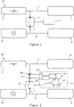
- FIG. 1 shows a schematic illustration of such a conventional arrangement within a vehicle power distribution architecture 10.
- a battery 2 provides the main power source for supplying energy to one or more critical modules 4 via a first power line 3.
- the non-critical modules 5 are supplied via a second power line 8 connected to the vehicle's generator or DC/DC converter 9 for supplying these modules when the vehicle is running.
- a charging line 7 is provided between the first power line 3 and the second power line 8.
- the generator or DC/DC-Converter 9 will charge the battery 2 by applying a forward current through the charging line 7.
- a switch 6 is provided on the charging line 7 and is controlled by a protection controller 11.
- the protection controller 11 monitors the voltage on the charging line 7 and, in response to the detection of a change in the voltage exceeding a threshold (e.g. an increase above a voltage threshold, or a drop below a threshold), will output a control signal for opening the switch 6. This thereby allows the critical modules 4 to be disconnected from the secondary power line 8.
- a threshold e.g. an increase above a voltage threshold, or a drop below a threshold
- the issue of damage to the switch 6 may also be further exacerbated by unnecessary switching in response to transient anomalies, such as electromagnetic compatibility (EMC) disturbances and microcurrents. That is, the protection system is typically required to react within 100 ⁇ s for automotive applications. However, this fast reaction time makes the system sensitive to temporary disturbances. This can cause the switch 6 to be subjected to a higher number of operating cycles, which together with the energy applied, lead to reduced switch lifespan. At the same time, unnecessary switching can lead to the supply of power to the non-critical modules 5 being interrupted unnecessarily.
- EMC electromagnetic compatibility
- a control device for controlling a switch in a charging line disposed between a first power line and a second power line in a power distribution architecture, the device including: a current level input for receiving a current measurement of the current conducted through the charging line; a voltage level input for receiving a voltage measurement of the voltage applied on the charging line; a monitor for monitoring the relationship between the current and voltage measurements and for generating a control signal for controlling the switch in response to a coherent change in the current and voltage measurements exceeding a threshold, and for not generating a control signal when a change in one of the current and voltage measurements exceeding a threshold is not associated with a coherent change in the other of the current and voltage measurements.
- a control device for a power protection switch may be provided which is able to differentiate between transient disturbances and more significant power disturbance events, such as an overcurrent or short circuit scenario. This determination may be based on the correlation between changes in current and voltage on the charging line. For example, a detected voltage drop which coincides with a corresponding increase in current as power is drawn through the charging line would be indicative of a disturbance event, such as an overcurrent or short circuit. In response, the controlling device may thereby trigger the switch to open for disconnecting the power lines. Conversely, a drop in measured voltage that does not coincide with a corresponding increase in current may be attributed to a transient disturbance which does not require disconnection. This thereby allows the system to maintain power to non-critical modules without unnecessary interruptions caused by transitory disturbances. As a consequence, the switching frequency is reduced, thereby mitigating potential damage to the switch and providing a triggering device with an improved reliability and lifespan.
- the monitor includes a mixer for combining the current and voltage measurements. In this way a current and voltage may be simultaneously compared in the time domain for identifying coherent changes in current and voltage.
- the monitor includes a microcontroller. In this way, the mixing of the current and voltage measurements may be provided in a programable digital solution. In other embodiments, the monitor may be implemented with analog electronic components.
- the monitor includes a current-voltage coherence model and wherein the monitor compares the current and voltage measurements to the current-voltage coherence model for identifying coherent changes in the current and voltage measurements.
- a predetermined model may be provided for defining an expected characteristic between current and voltage, and consequently a measured current and voltage that deviates from the expected characteristic may be attributed to a transient disturbance, rather than a substantive power supply disturbance event.
- At least one of the current level input, the voltage level input, and the monitor includes a filter. In this way, smaller transient disturbances may be filtered out.
- the filter is a Cauer filter.
- the Cauer or Elliptic filter may provide a fast transition in gain between the passband and stopband. This allows the filters to be finely tuned to filter out disturbances depending on the physical characteristics of the associated circuit components, whilst providing a high gain for valid signals.
- At least one of the current level input and the voltage level input includes a filter, wherein the filter is configured such that its stopband filters out transient disturbances in the respective current and voltage measurements.
- the threshold is a voltage threshold
- the monitor generates the control signal in response to a change in the voltage measurement exceeding the voltage threshold, where the change is associated with a coherent change in the current measurement.
- the voltage threshold is a minimum required voltage and wherein the monitor generates the control signal in response to a voltage drop exceeding the minimum required voltage threshold, where the voltage drop is associated with a coherent change in the current measurement.
- the controlling device may isolate the power lines in the event of, for example, a short circuit on the secondary power line. That is, a short circuit would cause a voltage drop on the charging line relative to the first power line. This in turn would act to draw a current through the charging line. This would thereby manifest as a measured drop in voltage coinciding with a coherent increase in measured current. As such, the controlling device may control the disconnection of the charging line.
- control signal is for controlling the switch for disconnecting the first power line from the second power line.
- the current level input further includes a current sensor for detecting the current measurement
- the voltage level input further includes a voltage sensor for detecting the voltage measurement.
- the controlling circuit may incorporate the sensors.
- a vehicle power distribution architecture including: a an energy store; a generator or DC/DC converter; a first power line for connecting the energy store to one or more critical modules; a second power line for connecting the generator or DC/DC converter to one or more non-critical modules; a charging line connected between the first power line and the second power line; a switch located on the charging line; and a controlling device for controlling the switch, wherein the controlling device includes a current level input for receiving a current measurement of the current conducted through the charging line; a voltage level input for receiving a voltage measurement of the voltage applied on the charging line; a monitor for monitoring the relationship between the current and voltage measurements and for generating a control signal for controlling the switch in response to a coherent change in the current and voltage measurements exceeding a threshold, and for not generating a control signal when a change in one of the current and voltage measurements exceeding a threshold is not associated with a coherent change in the other of the current and voltage measurements.
- FIG. 2 shows a control device 11 incorporated into a vehicle power distribution architecture 20 according to an illustrative embodiment.
- the architecture 20 includes a first power line 3 to connect between a battery 2 and one or more critical modules 4.
- a second power line 8 is provided between a generator or DC/DC converter 9 and one or more non-critical modules 5.
- a charging line 7 connects the battery 2 and the generator or DC/DC converter 9 via the first and second power lines 3,8.
- the charging line 7 includes a switch 6 that, when open, disconnects the first power line 3 from the second power line 8, similar to the arrangement shown in Figure 1 .
- the control device 11 is provided for controlling the opening and closing of the switch 6. As such, the control device 11 provides a triggering device for triggering a protection response.
- the control device 11 includes a mixer 16 and a logic module 18.
- the mixer 16 is connected to a current sensor 12 through a current Cauer filter 14 and is connected to a voltage sensor 13 through voltage Cauer filter 15.
- the current and voltage sensors and filters respectively form current and voltage inputs to the mixer 16 for inputting a current measurement and a voltage measurement, respectively.
- the mixer 16 and logic module 18 form a monitor for monitoring the measured current and voltage received from the current and voltage sensors 12,13.
- the mixer combines the current and voltage measurements in the time domain for comparing the coherence of the two measurements.
- the mixer 16 subtracts the current measurement from the voltage measurement and outputs a correlated value to the controller 16 that is indicative of the coherence between the two measurements. That is, if the rate of change in one of the measurements is not reflected in a corresponding change in the other, the delta output will increase, indicating a transient disturbance, as is described in further detail below.
- the output of the mixer 16 is fed through a mixer Cauer filter 17 to the logic module 18.
- the mixer Cauer filter 17 is configured to filter out any transient disturbances from the correlated value.
- the logic module 18 receives the correlated value reading from the mixer 16 and based on a logic determination generates a control signal for controlling the opening of the switch 6 to disconnect the first power line 3 from the second power line 8.
- the logic determination is based on the voltage measured by voltage sensor 13 dropping below a threshold, at the same time as a coherent increase in the current measured by current sensor 12.
- Figure 3 shows schematic illustrations of the current and voltage responses in an example power event scenario.
- Figure 3a shows the voltage 31 over a time period which includes three detected disturbances.
- the first event 32 is a short transient disturbance in which the voltage drops only briefly.
- the second event 33 is a more prolonged transient disturbance associated with a longer measured voltage drop.
- the third event 34 is a significant disturbance event caused by a short circuit on the secondary power line 8. In this case, following the event, there is a sustained voltage drop from a higher Vbat level down to a low level.
- Figure 3b shows the current 35 over the same time period shown in Figure 3a .
- the short transient disturbance may be recorded as a momentary spike in current. This may occur, for instance, if a transitory interference disturbance effects both the current and voltage sensors 12,13 simultaneously.
- the second event 33 of the more prolonged transient disturbance does not produce a corresponding increase in the current. This is because the transient disturbance does not generate an actual voltage drop on the charging line 7 which would cause a reverse current flow through the charging line.
- the third event 34 arising from a short circuit on the secondary power line 8 causes a reverse current to flow, driven by the voltage drop across the charging line 7.
- Figure 3c shows a combined plot of measured voltage 31 and current 35 from figures 3a and 3b .
- the momentary spike in current associated with the first event 32 has been filtered by the current Cauer filter 14.
- the drop in measured voltage 31 associated with this event does not coincide with a coherent spike in current 35.
- longer measured voltage drop associated with the second event 33 also does not coincide with a coherent increase in current 35.
- the third event 34 results both in a sustained drop in voltage 31, along with a coherent increase in current 35. Consequently, transient events can be differentiated from substantive disturbance events, such as short circuits, based on the coherence of the voltage and current response.
- figure 4 shows a schematic illustration of an example coherence model implemented by the mixer 16 and logic module 18.
- the change in measured voltage ( ⁇ V) is plotted against change in measured current ( ⁇ I), with the expected characteristics being based on the physical properties of the components.
- a large change e.g. drop
- a large change in measured current e.g. an increase
- measured values are in the invalid coherence region 36, these may be determined to arise from transient disturbances.
- measured values in the valid coherence region 37 would be deemed indicative of valid measurements.
- the logic module 18 applies a voltage threshold 40 to indicate the occurrence of a substantive disturbance event, such as a short circuit.
- the validity of such an event is determined based on whether it occurs within the valid coherence region 37 shown in Figure 4 . That is, where there is a change in voltage exceeding the threshold 40 which also coincides with a measured change within the valid coherence region 37, the logic module 18 generates a control signal for disconnecting the switch 6. In contrast, if the measured change in voltage exceeds the threshold 40, but the change in current is within the invalid coherence region 36, the logic module 18 does not trigger the control signal. The switch 6 may thereby be held in its closed state for maintaining operation of the non-critical modules 5.
- FIGs 5a and 5b explain this operation in further detail by contrasting the prior art switch control with the illustrative embodiment.
- a prior art controller 11 is subjected to the example power event scenario set out in Figure 3 .
- the prior art controller may use conventional filtering to ignore the very short first disturbance event 32.
- the second event 33 causes a more prolonged drop in voltage which cannot be filtered conventionally.
- the effect of the voltage exceeding the threshold 40 i.e. dropping below it
- the switch 6 transitions from a closed state 42 to an open state 43 at the protection triggering point 41.
- the non-critical modules are disconnected from the battery 2 well before a substantive event occurs, if at all.
- Figure 5b shows the illustrative embodiment in the same scenario.
- the first disturbance event 32 is ignored by filtering.
- the voltage drop 31 is also ignored because this doesn't coincide with a coherent increase in current. This is illustrated by the correlated current/voltage measurement line 50 in Figure 5b remaining flat during this disturbance.
- the logic module 18 triggers the control signal to open the switch 6.
- the protection triggering point 41 in figure 5b is much later. Consequently, the switch is maintained in the closed state 42 for longer.
- control device 11 is able to react quickly (e.g. in less than 100 ⁇ s) to protect the critical modules 4, whilst avoiding the need to unnecessarily disconnect the non-critical modules 5 because of transient disturbances. This thereby provides both better operation and a more robust system.
- implementations may be used in conjunction with one or more microprocessors, for instance to provide performance feedback and fault monitoring.
Landscapes
- Engineering & Computer Science (AREA)
- Power Engineering (AREA)
- Mechanical Engineering (AREA)
- Life Sciences & Earth Sciences (AREA)
- Sustainable Development (AREA)
- Sustainable Energy (AREA)
- Transportation (AREA)
- Charge And Discharge Circuits For Batteries Or The Like (AREA)
Abstract
Description
- The present disclosure relates to a control device for a vehicle power architecture and a vehicle power distribution architecture. The present disclosure is particularly relevant to automotive power safety devices, and systems and devices for current protection in vehicle power lines.
- Energy distribution within automotive applications is an important consideration when designing system architectures. Given the increasing prevalence of autonomous driving and the integration of enhanced safety technologies, a standard vehicle now possesses many automotive modules which require a supply of power. Importantly, it is common to differentiate between critical and non-critical modules. Critical modules are those that are paramount to safe operation of the vehicle and would normally include steering, advanced driver-assistance system (ADAS), and braking functionality. In contrast, non-critical modules would normally include interior lighting, media, and climate control systems. Due to the importance of critical modules, it is desirable to ensure that the power architecture provides for those modules to be connected to a power line that is unaffected by disturbances that might arise from varying energy availability.
- In this respect, in the event of a loss of power, some non-critical modules may be configured to be preventatively disabled in order that the remaining power supply is directed towards the critical modules for as long as possible. For this, automotive power architectures may isolate the critical modules on a first power line, whilst the non-critical modules are kept apart on a second power line. However, a charging line is required between these power lines to allow the energy store, such as a battery or supercapacitor, to be charged when the vehicle is running normally.
- In view of the above, a fuse may be provided in the charging line in order to protect the energy store and the critical modules in the event of a short circuit. That is, a short circuit on the second power line may cause a relatively high reverse current to be drawn from the energy store. This would result in the voltage on the first power line dropping low, which may affect the operation of the critical modules. The provision of the fuse can prevent this by breaking the connection when the reverse current exceeds the fuse's threshold. However, a problem with this solution is that the fuse will only melt if the energy store is sufficiently charged to supply a current exceeding the rating of the fuse. This is not always the case.
- To address the above, more modern arrangements replace the melting fuse with a switch or a number of field effect transistor (FET) switches under the control of a controller.
Figure 1 shows a schematic illustration of such a conventional arrangement within a vehiclepower distribution architecture 10. In this architecture, abattery 2 provides the main power source for supplying energy to one or morecritical modules 4 via afirst power line 3. Simultaneously, thenon-critical modules 5 are supplied via asecond power line 8 connected to the vehicle's generator or DC/DC converter 9 for supplying these modules when the vehicle is running. Furthermore, acharging line 7 is provided between thefirst power line 3 and thesecond power line 8. When the vehicle is running, the generator or DC/DC-Converter 9 will charge thebattery 2 by applying a forward current through thecharging line 7. However, to protect thefirst power line 3 in the event of a disturbance on thesecond power line 8, aswitch 6 is provided on thecharging line 7 and is controlled by aprotection controller 11. Theprotection controller 11 monitors the voltage on thecharging line 7 and, in response to the detection of a change in the voltage exceeding a threshold (e.g. an increase above a voltage threshold, or a drop below a threshold), will output a control signal for opening theswitch 6. This thereby allows thecritical modules 4 to be disconnected from thesecondary power line 8. - There are however a number of problems with these existing architectures. Firstly, in opening the
switch 6 to disconnect thefirst power line 3 from thesecond power line 8, significant damage can occur to theswitch 6 itself. This is in part due to the relatively high amounts of energy that may be delivered by the system. For example, if the current through thecharging line 7 is over 200A, many joules of energy will be applied to the switch, which can lead to damage or compromise its long-term reliability. Furthermore, the dissipation of energy may also necessitate the provision of heat sinks and thermal management systems to maintain operation of the switch. This increases the cost and size of the assembly as a whole. - The issue of damage to the
switch 6 may also be further exacerbated by unnecessary switching in response to transient anomalies, such as electromagnetic compatibility (EMC) disturbances and microcurrents. That is, the protection system is typically required to react within 100µs for automotive applications. However, this fast reaction time makes the system sensitive to temporary disturbances. This can cause theswitch 6 to be subjected to a higher number of operating cycles, which together with the energy applied, lead to reduced switch lifespan. At the same time, unnecessary switching can lead to the supply of power to thenon-critical modules 5 being interrupted unnecessarily. - In view of the above, there remains a need for an improved protection device for a vehicle power distribution architecture.
- According to a first aspect, there is provided a control device for controlling a switch in a charging line disposed between a first power line and a second power line in a power distribution architecture, the device including: a current level input for receiving a current measurement of the current conducted through the charging line; a voltage level input for receiving a voltage measurement of the voltage applied on the charging line; a monitor for monitoring the relationship between the current and voltage measurements and for generating a control signal for controlling the switch in response to a coherent change in the current and voltage measurements exceeding a threshold, and for not generating a control signal when a change in one of the current and voltage measurements exceeding a threshold is not associated with a coherent change in the other of the current and voltage measurements.
- In this way, a control device for a power protection switch may be provided which is able to differentiate between transient disturbances and more significant power disturbance events, such as an overcurrent or short circuit scenario. This determination may be based on the correlation between changes in current and voltage on the charging line. For example, a detected voltage drop which coincides with a corresponding increase in current as power is drawn through the charging line would be indicative of a disturbance event, such as an overcurrent or short circuit. In response, the controlling device may thereby trigger the switch to open for disconnecting the power lines. Conversely, a drop in measured voltage that does not coincide with a corresponding increase in current may be attributed to a transient disturbance which does not require disconnection. This thereby allows the system to maintain power to non-critical modules without unnecessary interruptions caused by transitory disturbances. As a consequence, the switching frequency is reduced, thereby mitigating potential damage to the switch and providing a triggering device with an improved reliability and lifespan.
- In embodiments, the monitor includes a mixer for combining the current and voltage measurements. In this way a current and voltage may be simultaneously compared in the time domain for identifying coherent changes in current and voltage.
- In embodiments, the monitor includes a microcontroller. In this way, the mixing of the current and voltage measurements may be provided in a programable digital solution. In other embodiments, the monitor may be implemented with analog electronic components.
- In embodiments, the monitor includes a current-voltage coherence model and wherein the monitor compares the current and voltage measurements to the current-voltage coherence model for identifying coherent changes in the current and voltage measurements. In this way, a predetermined model may be provided for defining an expected characteristic between current and voltage, and consequently a measured current and voltage that deviates from the expected characteristic may be attributed to a transient disturbance, rather than a substantive power supply disturbance event.
- In embodiments, at least one of the current level input, the voltage level input, and the monitor includes a filter. In this way, smaller transient disturbances may be filtered out.
- In embodiments, the filter is a Cauer filter. In this way, the Cauer or Elliptic filter may provide a fast transition in gain between the passband and stopband. This allows the filters to be finely tuned to filter out disturbances depending on the physical characteristics of the associated circuit components, whilst providing a high gain for valid signals.
- In embodiments, at least one of the current level input and the voltage level input includes a filter, wherein the filter is configured such that its stopband filters out transient disturbances in the respective current and voltage measurements.
- In embodiments, the threshold is a voltage threshold, and wherein the monitor generates the control signal in response to a change in the voltage measurement exceeding the voltage threshold, where the change is associated with a coherent change in the current measurement. In this way, a voltage change greater than the threshold which results in a current flow may be identified as a power event and prompt the controlling device to open the switch.
- In embodiments, the voltage threshold is a minimum required voltage and wherein the monitor generates the control signal in response to a voltage drop exceeding the minimum required voltage threshold, where the voltage drop is associated with a coherent change in the current measurement. In this way, the controlling device may isolate the power lines in the event of, for example, a short circuit on the secondary power line. That is, a short circuit would cause a voltage drop on the charging line relative to the first power line. This in turn would act to draw a current through the charging line. This would thereby manifest as a measured drop in voltage coinciding with a coherent increase in measured current. As such, the controlling device may control the disconnection of the charging line.
- In embodiments, the control signal is for controlling the switch for disconnecting the first power line from the second power line.
- In embodiments, the current level input further includes a current sensor for detecting the current measurement, and wherein the voltage level input further includes a voltage sensor for detecting the voltage measurement. In this way, the controlling circuit may incorporate the sensors.
- According to a second aspect, there is provided a vehicle power distribution architecture including: a an energy store; a generator or DC/DC converter; a first power line for connecting the energy store to one or more critical modules; a second power line for connecting the generator or DC/DC converter to one or more non-critical modules; a charging line connected between the first power line and the second power line; a switch located on the charging line; and a controlling device for controlling the switch, wherein the controlling device includes a current level input for receiving a current measurement of the current conducted through the charging line; a voltage level input for receiving a voltage measurement of the voltage applied on the charging line; a monitor for monitoring the relationship between the current and voltage measurements and for generating a control signal for controlling the switch in response to a coherent change in the current and voltage measurements exceeding a threshold, and for not generating a control signal when a change in one of the current and voltage measurements exceeding a threshold is not associated with a coherent change in the other of the current and voltage measurements.
- Illustrative embodiments will now be described with reference to the accompanying drawings in which:
-
Figure 1 shows a schematic illustration of a vehicle power distribution architecture according to the prior art; -
Figure 2 shows a schematic illustration of a vehicle power distribution architecture incorporating a control device according to an illustrative embodiment; -
Figure 3 shows schematic illustrations of the current and voltage responses in an example power event scenario; -
Figure 4 shows a schematic illustration of an example coherence model implemented by the control device; -
Figure 5a shows a schematic illustration of the combined current and voltage response in the example power event scenario with the prior art vehicle power distribution architecture; and -
Figure 5b shows a schematic illustration of the combined current and voltage response in the example power event scenario with the vehicle power distribution architecture according to the illustrative embodiment. -
Figure 2 shows acontrol device 11 incorporated into a vehiclepower distribution architecture 20 according to an illustrative embodiment. Thearchitecture 20 includes afirst power line 3 to connect between abattery 2 and one or morecritical modules 4. Asecond power line 8 is provided between a generator or DC/DC converter 9 and one or morenon-critical modules 5. A chargingline 7 connects thebattery 2 and the generator or DC/DC converter 9 via the first andsecond power lines line 7 includes aswitch 6 that, when open, disconnects thefirst power line 3 from thesecond power line 8, similar to the arrangement shown inFigure 1 . - The
control device 11 is provided for controlling the opening and closing of theswitch 6. As such, thecontrol device 11 provides a triggering device for triggering a protection response. - The
control device 11 includes amixer 16 and alogic module 18. Themixer 16 is connected to acurrent sensor 12 through acurrent Cauer filter 14 and is connected to avoltage sensor 13 throughvoltage Cauer filter 15. As such, the current and voltage sensors and filters respectively form current and voltage inputs to themixer 16 for inputting a current measurement and a voltage measurement, respectively. - The
mixer 16 andlogic module 18 form a monitor for monitoring the measured current and voltage received from the current andvoltage sensors mixer 16 subtracts the current measurement from the voltage measurement and outputs a correlated value to thecontroller 16 that is indicative of the coherence between the two measurements. That is, if the rate of change in one of the measurements is not reflected in a corresponding change in the other, the delta output will increase, indicating a transient disturbance, as is described in further detail below. - In this embodiment, the output of the
mixer 16 is fed through amixer Cauer filter 17 to thelogic module 18. Themixer Cauer filter 17 is configured to filter out any transient disturbances from the correlated value. - The
logic module 18 receives the correlated value reading from themixer 16 and based on a logic determination generates a control signal for controlling the opening of theswitch 6 to disconnect thefirst power line 3 from thesecond power line 8. As described in further detail below, in this embodiment, the logic determination is based on the voltage measured byvoltage sensor 13 dropping below a threshold, at the same time as a coherent increase in the current measured bycurrent sensor 12. - In this connection,
Figure 3 shows schematic illustrations of the current and voltage responses in an example power event scenario.Figure 3a shows thevoltage 31 over a time period which includes three detected disturbances. Thefirst event 32 is a short transient disturbance in which the voltage drops only briefly. Thesecond event 33 is a more prolonged transient disturbance associated with a longer measured voltage drop. Thethird event 34 is a significant disturbance event caused by a short circuit on thesecondary power line 8. In this case, following the event, there is a sustained voltage drop from a higher Vbat level down to a low level. -
Figure 3b shows the current 35 over the same time period shown inFigure 3a . In this case, in thefirst event 32, the short transient disturbance may be recorded as a momentary spike in current. This may occur, for instance, if a transitory interference disturbance effects both the current andvoltage sensors second event 33 of the more prolonged transient disturbance does not produce a corresponding increase in the current. This is because the transient disturbance does not generate an actual voltage drop on thecharging line 7 which would cause a reverse current flow through the charging line. Conversely, thethird event 34 arising from a short circuit on thesecondary power line 8 causes a reverse current to flow, driven by the voltage drop across the chargingline 7. -
Figure 3c shows a combined plot of measuredvoltage 31 and current 35 fromfigures 3a and 3b . In this case, the momentary spike in current associated with thefirst event 32 has been filtered by thecurrent Cauer filter 14. As such, the drop in measuredvoltage 31 associated with this event does not coincide with a coherent spike in current 35. Equally, longer measured voltage drop associated with thesecond event 33 also does not coincide with a coherent increase in current 35. However, thethird event 34 results both in a sustained drop involtage 31, along with a coherent increase in current 35. Consequently, transient events can be differentiated from substantive disturbance events, such as short circuits, based on the coherence of the voltage and current response. - In this connection,
figure 4 shows a schematic illustration of an example coherence model implemented by themixer 16 andlogic module 18. In this model, the change in measured voltage (ΔV) is plotted against change in measured current (ΔI), with the expected characteristics being based on the physical properties of the components. Where a large change (e.g. drop) in measured voltage (V) is detected, it would be expected for this to coincide with a large change in measured current (e.g. an increase). Accordingly, when the measured values are in theinvalid coherence region 36, these may be determined to arise from transient disturbances. Conversely, measured values in thevalid coherence region 37 would be deemed indicative of valid measurements. - At the same time as the above, the
logic module 18 applies avoltage threshold 40 to indicate the occurrence of a substantive disturbance event, such as a short circuit. The validity of such an event is determined based on whether it occurs within thevalid coherence region 37 shown inFigure 4 . That is, where there is a change in voltage exceeding thethreshold 40 which also coincides with a measured change within thevalid coherence region 37, thelogic module 18 generates a control signal for disconnecting theswitch 6. In contrast, if the measured change in voltage exceeds thethreshold 40, but the change in current is within theinvalid coherence region 36, thelogic module 18 does not trigger the control signal. Theswitch 6 may thereby be held in its closed state for maintaining operation of thenon-critical modules 5. -
Figures 5a and 5b explain this operation in further detail by contrasting the prior art switch control with the illustrative embodiment. InFigure 5a , aprior art controller 11 is subjected to the example power event scenario set out inFigure 3 . The prior art controller may use conventional filtering to ignore the very shortfirst disturbance event 32. However, thesecond event 33 causes a more prolonged drop in voltage which cannot be filtered conventionally. As the system has no awareness that this is merely a transient disturbance, the effect of the voltage exceeding the threshold 40 (i.e. dropping below it), triggers the generation of a control signal for opening theswitch 6. Therefore, theswitch 6 transitions from aclosed state 42 to anopen state 43 at theprotection triggering point 41. As such, the non-critical modules are disconnected from thebattery 2 well before a substantive event occurs, if at all. - In contrast to the above,
Figure 5b , shows the illustrative embodiment in the same scenario. Again, thefirst disturbance event 32 is ignored by filtering. For the second event, thevoltage drop 31 is also ignored because this doesn't coincide with a coherent increase in current. This is illustrated by the correlated current/voltage measurement line 50 inFigure 5b remaining flat during this disturbance. However, if there is a significant disturbance event, caused by a short circuit, the current and voltage both change coherently, as shown by the correlated current/voltage measurement line 50. Once this exceeds the threshold 40 (i.e. drops below it), thelogic module 18 triggers the control signal to open theswitch 6. Importantly, as shown in contrast toFigure 5a , theprotection triggering point 41 infigure 5b is much later. Consequently, the switch is maintained in theclosed state 42 for longer. - In this way, the
control device 11 is able to react quickly (e.g. in less than 100 µs) to protect thecritical modules 4, whilst avoiding the need to unnecessarily disconnect thenon-critical modules 5 because of transient disturbances. This thereby provides both better operation and a more robust system. - It will be understood that the embodiment illustrated above show an application only for the purposes of illustration. In practice, embodiments may be applied to many different configurations, the detailed embodiments being straightforward for those skilled in the art to implement.
- For example, although the arrangement allows for short circuit protection without the need for complex microprocessors, it will be understood that implementations may be used in conjunction with one or more microprocessors, for instance to provide performance feedback and fault monitoring.
- It will also be understood that although the above illustrative architecture uses a battery, other energy stores, such as supercapacitors or an array of batteries may be alternatively used.
Claims (13)
- A control device for controlling a switch in a charging line disposed between a first power line and a second power line in a power distribution architecture, the device comprising:a current level input for receiving a current measurement of the current conducted through the charging line;a voltage level input for receiving a voltage measurement of the voltage applied on the charging line;a monitor for monitoring the relationship between the current and voltage measurements and for generating a control signal for controlling the switch in response to a coherent change in the current and voltage measurements exceeding a threshold, and for not generating a control signal when a change in one of the current and voltage measurements exceeding a threshold is not associated with a coherent change in the other of the current and voltage measurements.
- A control device according to claim 1, wherein the monitor comprises a mixer for combining the current and voltage measurements.
- A control device according to claim 1 or 2 wherein the monitor comprises a microcontroller.
- A control device according to any preceding claim wherein the monitor comprises a current-voltage coherence model and wherein the monitor compares the current and voltage measurements to the current-voltage coherence model for identifying coherent changes in the current and voltage measurements.
- A control device according to any preceding claim, wherein at least one of the current level input, the voltage level input, and the monitor comprises a filter.
- A control device according to claim 5, wherein the filter is a Cauer filter.
- A control device according to claim 5 or 6 wherein at least one of the current level input and the voltage level input comprises a filter, wherein the filter is configured such that its stopband filters out transient disturbances in the respective current and voltage and current measurement.
- A control device according to any preceding claim, wherein the threshold is a voltage threshold, and wherein the monitor generates the control signal in response to a change in the voltage measurement exceeding the voltage threshold, where the change is associated with a coherent change in the current measurement.
- A control device according to claim 8 wherein the voltage threshold is a minimum required voltage and wherein the monitor generates the control signal in response to a voltage drop exceeding the minimum required voltage threshold, where the voltage drop is associated with a coherent change in the current measurement.
- A control device according to any preceding claim wherein the control signal is for controlling the switch for disconnecting the first power line from the second power line.
- A control device according to any preceding claim, wherein the current level input further comprises a current sensor for detecting the current measurement, and wherein the voltage level input further comprises a voltage sensor for detecting the voltage measurement.
- A vehicle power distribution architecture comprising:an energy store;a generator or DC/DC converter;a first power line for connecting the energy store to one or more critical modules;a second power line for connecting the generator or DC/DC converter to one or more non-critical modules;a charging line connected between the first power line and the second power line;a switch located on the charging line; anda controlling device for controlling the switch, wherein the controlling device comprisesa current level input for receiving a current measurement of the current conducted through the charging line;a voltage level input for receiving a voltage measurement of the voltage applied on the charging line;a monitor for monitoring the relationship between the current and voltage measurements and for generating a control signal for controlling the switch in response to a coherent change in the current and voltage measurements exceeding a threshold, and for not generating a control signal when a change in one of the current and voltage measurements exceeding a threshold is not associated with a coherent change in the other of the current and voltage measurements.
- A vehicle power distribution architecture according to claim 12, wherein the energy store comprises at least one of a battery and a supercapacitor.
Priority Applications (3)
| Application Number | Priority Date | Filing Date | Title |
|---|---|---|---|
| EP21177800.6A EP4098493B1 (en) | 2021-06-04 | 2021-06-04 | Control device and vehicle power distribution architecture incorporating the same |
| CN202210620469.XA CN115441530A (en) | 2021-06-04 | 2022-06-02 | Control device and vehicle power distribution architecture comprising same |
| US17/805,334 US11642979B2 (en) | 2021-06-04 | 2022-06-03 | Control device and vehicle power distribution architecture incorporating the same |
Applications Claiming Priority (1)
| Application Number | Priority Date | Filing Date | Title |
|---|---|---|---|
| EP21177800.6A EP4098493B1 (en) | 2021-06-04 | 2021-06-04 | Control device and vehicle power distribution architecture incorporating the same |
Publications (2)
| Publication Number | Publication Date |
|---|---|
| EP4098493A1 true EP4098493A1 (en) | 2022-12-07 |
| EP4098493B1 EP4098493B1 (en) | 2024-02-14 |
Family
ID=76283640
Family Applications (1)
| Application Number | Title | Priority Date | Filing Date |
|---|---|---|---|
| EP21177800.6A Active EP4098493B1 (en) | 2021-06-04 | 2021-06-04 | Control device and vehicle power distribution architecture incorporating the same |
Country Status (3)
| Country | Link |
|---|---|
| US (1) | US11642979B2 (en) |
| EP (1) | EP4098493B1 (en) |
| CN (1) | CN115441530A (en) |
Families Citing this family (2)
| Publication number | Priority date | Publication date | Assignee | Title |
|---|---|---|---|---|
| AU2018336995B2 (en) * | 2017-09-22 | 2021-09-09 | The Noco Company | Rechargeable battery jump starting device with control switch backlight system |
| EP4588724A1 (en) * | 2024-01-18 | 2025-07-23 | Aptiv Technologies AG | Undervoltage protection system for power supply management |
Citations (2)
| Publication number | Priority date | Publication date | Assignee | Title |
|---|---|---|---|---|
| US20180229676A1 (en) * | 2017-02-16 | 2018-08-16 | Ford Global Technologies, Llc | Short-circuit protection for vehicle redundant power architecture |
| US20190131804A1 (en) * | 2016-04-18 | 2019-05-02 | Autonetworks Technologies, Ltd. | Relay device and in-vehicle system |
Family Cites Families (17)
| Publication number | Priority date | Publication date | Assignee | Title |
|---|---|---|---|---|
| KR100756417B1 (en) * | 2007-03-29 | 2007-09-07 | 한국생산기술연구원 | External Waveform Current Waveform Control Device for Welding |
| WO2009014143A1 (en) * | 2007-07-24 | 2009-01-29 | Panasonic Electric Works Co., Ltd. | Charge monitoring device |
| JP4315232B1 (en) * | 2008-03-17 | 2009-08-19 | トヨタ自動車株式会社 | Electric vehicle |
| DE102009000674A1 (en) * | 2009-02-06 | 2010-08-12 | Robert Bosch Gmbh | Traction battery with increased availability |
| JP5509431B2 (en) * | 2010-03-31 | 2014-06-04 | 株式会社Nttファシリティーズ | Semiconductor circuit breaker and DC power supply system |
| JP2012029435A (en) * | 2010-07-22 | 2012-02-09 | Shindengen Electric Mfg Co Ltd | Power supply device and protection method of the same |
| CN102653263B (en) * | 2011-03-03 | 2014-08-06 | 北汽福田汽车股份有限公司 | Electric automobile power battery management system and method |
| JP2013055844A (en) * | 2011-09-06 | 2013-03-21 | Toshiba Corp | Power supply device for vehicle |
| US9061599B2 (en) * | 2013-01-11 | 2015-06-23 | Johnson Controls Technology Company | System and method for optimizing the storing of vehicular energy |
| EP2811548B1 (en) * | 2013-06-07 | 2017-08-09 | Autoliv Development AB | Battery module disconnect arrangement |
| JP5946436B2 (en) * | 2013-10-21 | 2016-07-06 | カルソニックカンセイ株式会社 | Battery parameter estimation apparatus and parameter estimation method |
| JP6551358B2 (en) * | 2016-10-13 | 2019-07-31 | トヨタ自動車株式会社 | vehicle |
| US9979371B1 (en) * | 2017-03-02 | 2018-05-22 | Futurewei Technologies, Inc. | Elliptic directional filters for a combiner circuit |
| JP6951662B2 (en) * | 2017-08-31 | 2021-10-20 | 株式会社オートネットワーク技術研究所 | Power system |
| JP6901414B2 (en) * | 2018-01-19 | 2021-07-14 | トヨタ自動車株式会社 | Secondary battery system and vehicles equipped with it and how to control the battery |
| JP7035571B2 (en) * | 2018-01-31 | 2022-03-15 | トヨタ自動車株式会社 | Electric vehicle |
| US11097633B1 (en) * | 2019-01-24 | 2021-08-24 | Veritone Alpha, Inc. | Using battery state excitation to model and control battery operations |
-
2021
- 2021-06-04 EP EP21177800.6A patent/EP4098493B1/en active Active
-
2022
- 2022-06-02 CN CN202210620469.XA patent/CN115441530A/en active Pending
- 2022-06-03 US US17/805,334 patent/US11642979B2/en active Active
Patent Citations (2)
| Publication number | Priority date | Publication date | Assignee | Title |
|---|---|---|---|---|
| US20190131804A1 (en) * | 2016-04-18 | 2019-05-02 | Autonetworks Technologies, Ltd. | Relay device and in-vehicle system |
| US20180229676A1 (en) * | 2017-02-16 | 2018-08-16 | Ford Global Technologies, Llc | Short-circuit protection for vehicle redundant power architecture |
Also Published As
| Publication number | Publication date |
|---|---|
| US11642979B2 (en) | 2023-05-09 |
| CN115441530A (en) | 2022-12-06 |
| EP4098493B1 (en) | 2024-02-14 |
| US20220388423A1 (en) | 2022-12-08 |
Similar Documents
| Publication | Publication Date | Title |
|---|---|---|
| US11381072B2 (en) | Quick battery disconnect system for high current circuits | |
| JP7001970B2 (en) | Ground fault detection device and power storage system | |
| US9806522B2 (en) | Method for the controlled connection of a plurality of on-board power system branches of a vehicle, control unit for carrying out the method and on-board power system | |
| US11491877B2 (en) | Protection circuit for in-vehicle battery | |
| US8518570B2 (en) | Battery system | |
| US11642979B2 (en) | Control device and vehicle power distribution architecture incorporating the same | |
| US20090015973A1 (en) | Increased Voltage Vehicle Electrical System | |
| US20170187179A1 (en) | Junction box | |
| WO2013153889A1 (en) | Battery pack provided with charge and discharge control switch circuit | |
| CN111584816A (en) | Protection device, battery, motor vehicle, and method for shutting down battery cells | |
| US11173788B2 (en) | Method and device for operating a motor vehicle | |
| US10367345B2 (en) | Temperature detection device | |
| US9209616B2 (en) | Power supply circuit for on board energy source or storage device and particularly for super-capacitor storage unit | |
| WO2026001302A1 (en) | Battery management control system and control method, and vehicle | |
| US12021372B2 (en) | Power supply system with protection against current variations | |
| US20240201242A1 (en) | Device for monitoring a power distributor of a motor vehicle | |
| US11862963B2 (en) | Electrical system redundant overvoltage protection | |
| JP5884683B2 (en) | Battery monitoring device | |
| WO2023026922A1 (en) | Backup power supply system, mobile object, backup power supply system controlling method, and program | |
| US12172590B2 (en) | Vehicle power distribution circuit and vehicle power system | |
| JP7723903B2 (en) | Shut-off control device | |
| KR20170064484A (en) | CIRCUIT ARCHITECTURES FOR PROTECTING AGAINST PoDL WIRE FAULTS | |
| JP2022541865A (en) | Electrochemical device, electrical equipment, electric vehicle, and power supply control method | |
| JP2023119789A (en) | vehicle power supply | |
| JP2025160545A (en) | Charging control device and battery pack |
Legal Events
| Date | Code | Title | Description |
|---|---|---|---|
| PUAI | Public reference made under article 153(3) epc to a published international application that has entered the european phase |
Free format text: ORIGINAL CODE: 0009012 |
|
| STAA | Information on the status of an ep patent application or granted ep patent |
Free format text: STATUS: THE APPLICATION HAS BEEN PUBLISHED |
|
| AK | Designated contracting states |
Kind code of ref document: A1 Designated state(s): AL AT BE BG CH CY CZ DE DK EE ES FI FR GB GR HR HU IE IS IT LI LT LU LV MC MK MT NL NO PL PT RO RS SE SI SK SM TR |
|
| RAP3 | Party data changed (applicant data changed or rights of an application transferred) |
Owner name: APTIV TECHNOLOGIES LIMITED |
|
| STAA | Information on the status of an ep patent application or granted ep patent |
Free format text: STATUS: REQUEST FOR EXAMINATION WAS MADE |
|
| 17P | Request for examination filed |
Effective date: 20230605 |
|
| RBV | Designated contracting states (corrected) |
Designated state(s): AL AT BE BG CH CY CZ DE DK EE ES FI FR GB GR HR HU IE IS IT LI LT LU LV MC MK MT NL NO PL PT RO RS SE SI SK SM TR |
|
| GRAP | Despatch of communication of intention to grant a patent |
Free format text: ORIGINAL CODE: EPIDOSNIGR1 |
|
| STAA | Information on the status of an ep patent application or granted ep patent |
Free format text: STATUS: GRANT OF PATENT IS INTENDED |
|
| INTG | Intention to grant announced |
Effective date: 20230907 |
|
| GRAS | Grant fee paid |
Free format text: ORIGINAL CODE: EPIDOSNIGR3 |
|
| GRAA | (expected) grant |
Free format text: ORIGINAL CODE: 0009210 |
|
| STAA | Information on the status of an ep patent application or granted ep patent |
Free format text: STATUS: THE PATENT HAS BEEN GRANTED |
|
| AK | Designated contracting states |
Kind code of ref document: B1 Designated state(s): AL AT BE BG CH CY CZ DE DK EE ES FI FR GB GR HR HU IE IS IT LI LT LU LV MC MK MT NL NO PL PT RO RS SE SI SK SM TR |
|
| REG | Reference to a national code |
Ref country code: GB Ref legal event code: FG4D |
|
| REG | Reference to a national code |
Ref country code: CH Ref legal event code: EP |
|
| P01 | Opt-out of the competence of the unified patent court (upc) registered |
Effective date: 20240125 |
|
| REG | Reference to a national code |
Ref country code: DE Ref legal event code: R096 Ref document number: 602021009318 Country of ref document: DE |
|
| REG | Reference to a national code |
Ref country code: IE Ref legal event code: FG4D |
|
| RAP2 | Party data changed (patent owner data changed or rights of a patent transferred) |
Owner name: APTIV TECHNOLOGIES AG |
|
| REG | Reference to a national code |
Ref country code: CH Ref legal event code: PK Free format text: DIE PUBLIKATION VOM 27.03.2024 WURDE AM 24.04.2024 IRRTUEMLICHERWEISE ERNEUT PUBLIZIERT. LA PUBLICATION DU 27.03.2024 A ETE REPUBLIEE PAR ERREUR LE 24.04.2024. LA PUBBLICAZIONE DEL 27.03.2024 E STATA ERRONEAMENTE RIPUBBLICATA IL 24.04.2024. |
|
| REG | Reference to a national code |
Ref country code: LT Ref legal event code: MG9D |
|
| REG | Reference to a national code |
Ref country code: NL Ref legal event code: MP Effective date: 20240214 |
|
| PG25 | Lapsed in a contracting state [announced via postgrant information from national office to epo] |
Ref country code: IS Free format text: LAPSE BECAUSE OF FAILURE TO SUBMIT A TRANSLATION OF THE DESCRIPTION OR TO PAY THE FEE WITHIN THE PRESCRIBED TIME-LIMIT Effective date: 20240614 |
|
| PG25 | Lapsed in a contracting state [announced via postgrant information from national office to epo] |
Ref country code: LT Free format text: LAPSE BECAUSE OF FAILURE TO SUBMIT A TRANSLATION OF THE DESCRIPTION OR TO PAY THE FEE WITHIN THE PRESCRIBED TIME-LIMIT Effective date: 20240214 |
|
| PG25 | Lapsed in a contracting state [announced via postgrant information from national office to epo] |
Ref country code: GR Free format text: LAPSE BECAUSE OF FAILURE TO SUBMIT A TRANSLATION OF THE DESCRIPTION OR TO PAY THE FEE WITHIN THE PRESCRIBED TIME-LIMIT Effective date: 20240515 |
|
| REG | Reference to a national code |
Ref country code: AT Ref legal event code: MK05 Ref document number: 1656796 Country of ref document: AT Kind code of ref document: T Effective date: 20240214 |
|
| PG25 | Lapsed in a contracting state [announced via postgrant information from national office to epo] |
Ref country code: HR Free format text: LAPSE BECAUSE OF FAILURE TO SUBMIT A TRANSLATION OF THE DESCRIPTION OR TO PAY THE FEE WITHIN THE PRESCRIBED TIME-LIMIT Effective date: 20240214 Ref country code: RS Free format text: LAPSE BECAUSE OF FAILURE TO SUBMIT A TRANSLATION OF THE DESCRIPTION OR TO PAY THE FEE WITHIN THE PRESCRIBED TIME-LIMIT Effective date: 20240514 Ref country code: NL Free format text: LAPSE BECAUSE OF FAILURE TO SUBMIT A TRANSLATION OF THE DESCRIPTION OR TO PAY THE FEE WITHIN THE PRESCRIBED TIME-LIMIT Effective date: 20240214 |
|
| PG25 | Lapsed in a contracting state [announced via postgrant information from national office to epo] |
Ref country code: ES Free format text: LAPSE BECAUSE OF FAILURE TO SUBMIT A TRANSLATION OF THE DESCRIPTION OR TO PAY THE FEE WITHIN THE PRESCRIBED TIME-LIMIT Effective date: 20240214 |
|
| PG25 | Lapsed in a contracting state [announced via postgrant information from national office to epo] |
Ref country code: AT Free format text: LAPSE BECAUSE OF FAILURE TO SUBMIT A TRANSLATION OF THE DESCRIPTION OR TO PAY THE FEE WITHIN THE PRESCRIBED TIME-LIMIT Effective date: 20240214 |
|
| PG25 | Lapsed in a contracting state [announced via postgrant information from national office to epo] |
Ref country code: RS Free format text: LAPSE BECAUSE OF FAILURE TO SUBMIT A TRANSLATION OF THE DESCRIPTION OR TO PAY THE FEE WITHIN THE PRESCRIBED TIME-LIMIT Effective date: 20240514 Ref country code: NO Free format text: LAPSE BECAUSE OF FAILURE TO SUBMIT A TRANSLATION OF THE DESCRIPTION OR TO PAY THE FEE WITHIN THE PRESCRIBED TIME-LIMIT Effective date: 20240514 Ref country code: NL Free format text: LAPSE BECAUSE OF FAILURE TO SUBMIT A TRANSLATION OF THE DESCRIPTION OR TO PAY THE FEE WITHIN THE PRESCRIBED TIME-LIMIT Effective date: 20240214 Ref country code: LT Free format text: LAPSE BECAUSE OF FAILURE TO SUBMIT A TRANSLATION OF THE DESCRIPTION OR TO PAY THE FEE WITHIN THE PRESCRIBED TIME-LIMIT Effective date: 20240214 Ref country code: IS Free format text: LAPSE BECAUSE OF FAILURE TO SUBMIT A TRANSLATION OF THE DESCRIPTION OR TO PAY THE FEE WITHIN THE PRESCRIBED TIME-LIMIT Effective date: 20240614 Ref country code: HR Free format text: LAPSE BECAUSE OF FAILURE TO SUBMIT A TRANSLATION OF THE DESCRIPTION OR TO PAY THE FEE WITHIN THE PRESCRIBED TIME-LIMIT Effective date: 20240214 Ref country code: GR Free format text: LAPSE BECAUSE OF FAILURE TO SUBMIT A TRANSLATION OF THE DESCRIPTION OR TO PAY THE FEE WITHIN THE PRESCRIBED TIME-LIMIT Effective date: 20240515 Ref country code: FI Free format text: LAPSE BECAUSE OF FAILURE TO SUBMIT A TRANSLATION OF THE DESCRIPTION OR TO PAY THE FEE WITHIN THE PRESCRIBED TIME-LIMIT Effective date: 20240214 Ref country code: ES Free format text: LAPSE BECAUSE OF FAILURE TO SUBMIT A TRANSLATION OF THE DESCRIPTION OR TO PAY THE FEE WITHIN THE PRESCRIBED TIME-LIMIT Effective date: 20240214 Ref country code: BG Free format text: LAPSE BECAUSE OF FAILURE TO SUBMIT A TRANSLATION OF THE DESCRIPTION OR TO PAY THE FEE WITHIN THE PRESCRIBED TIME-LIMIT Effective date: 20240214 Ref country code: AT Free format text: LAPSE BECAUSE OF FAILURE TO SUBMIT A TRANSLATION OF THE DESCRIPTION OR TO PAY THE FEE WITHIN THE PRESCRIBED TIME-LIMIT Effective date: 20240214 |
|
| PG25 | Lapsed in a contracting state [announced via postgrant information from national office to epo] |
Ref country code: PL Free format text: LAPSE BECAUSE OF FAILURE TO SUBMIT A TRANSLATION OF THE DESCRIPTION OR TO PAY THE FEE WITHIN THE PRESCRIBED TIME-LIMIT Effective date: 20240214 Ref country code: PT Free format text: LAPSE BECAUSE OF FAILURE TO SUBMIT A TRANSLATION OF THE DESCRIPTION OR TO PAY THE FEE WITHIN THE PRESCRIBED TIME-LIMIT Effective date: 20240614 |
|
| PG25 | Lapsed in a contracting state [announced via postgrant information from national office to epo] |
Ref country code: SE Free format text: LAPSE BECAUSE OF FAILURE TO SUBMIT A TRANSLATION OF THE DESCRIPTION OR TO PAY THE FEE WITHIN THE PRESCRIBED TIME-LIMIT Effective date: 20240214 Ref country code: PT Free format text: LAPSE BECAUSE OF FAILURE TO SUBMIT A TRANSLATION OF THE DESCRIPTION OR TO PAY THE FEE WITHIN THE PRESCRIBED TIME-LIMIT Effective date: 20240614 Ref country code: PL Free format text: LAPSE BECAUSE OF FAILURE TO SUBMIT A TRANSLATION OF THE DESCRIPTION OR TO PAY THE FEE WITHIN THE PRESCRIBED TIME-LIMIT Effective date: 20240214 Ref country code: LV Free format text: LAPSE BECAUSE OF FAILURE TO SUBMIT A TRANSLATION OF THE DESCRIPTION OR TO PAY THE FEE WITHIN THE PRESCRIBED TIME-LIMIT Effective date: 20240214 |
|
| RAP4 | Party data changed (patent owner data changed or rights of a patent transferred) |
Owner name: APTIV TECHNOLOGIES AG |
|
| PG25 | Lapsed in a contracting state [announced via postgrant information from national office to epo] |
Ref country code: DK Free format text: LAPSE BECAUSE OF FAILURE TO SUBMIT A TRANSLATION OF THE DESCRIPTION OR TO PAY THE FEE WITHIN THE PRESCRIBED TIME-LIMIT Effective date: 20240214 |
|
| PG25 | Lapsed in a contracting state [announced via postgrant information from national office to epo] |
Ref country code: SM Free format text: LAPSE BECAUSE OF FAILURE TO SUBMIT A TRANSLATION OF THE DESCRIPTION OR TO PAY THE FEE WITHIN THE PRESCRIBED TIME-LIMIT Effective date: 20240214 |
|
| PG25 | Lapsed in a contracting state [announced via postgrant information from national office to epo] |
Ref country code: EE Free format text: LAPSE BECAUSE OF FAILURE TO SUBMIT A TRANSLATION OF THE DESCRIPTION OR TO PAY THE FEE WITHIN THE PRESCRIBED TIME-LIMIT Effective date: 20240214 Ref country code: CZ Free format text: LAPSE BECAUSE OF FAILURE TO SUBMIT A TRANSLATION OF THE DESCRIPTION OR TO PAY THE FEE WITHIN THE PRESCRIBED TIME-LIMIT Effective date: 20240214 |
|
| PG25 | Lapsed in a contracting state [announced via postgrant information from national office to epo] |
Ref country code: SK Free format text: LAPSE BECAUSE OF FAILURE TO SUBMIT A TRANSLATION OF THE DESCRIPTION OR TO PAY THE FEE WITHIN THE PRESCRIBED TIME-LIMIT Effective date: 20240214 |
|
| PG25 | Lapsed in a contracting state [announced via postgrant information from national office to epo] |
Ref country code: SM Free format text: LAPSE BECAUSE OF FAILURE TO SUBMIT A TRANSLATION OF THE DESCRIPTION OR TO PAY THE FEE WITHIN THE PRESCRIBED TIME-LIMIT Effective date: 20240214 Ref country code: SK Free format text: LAPSE BECAUSE OF FAILURE TO SUBMIT A TRANSLATION OF THE DESCRIPTION OR TO PAY THE FEE WITHIN THE PRESCRIBED TIME-LIMIT Effective date: 20240214 Ref country code: RO Free format text: LAPSE BECAUSE OF FAILURE TO SUBMIT A TRANSLATION OF THE DESCRIPTION OR TO PAY THE FEE WITHIN THE PRESCRIBED TIME-LIMIT Effective date: 20240214 Ref country code: EE Free format text: LAPSE BECAUSE OF FAILURE TO SUBMIT A TRANSLATION OF THE DESCRIPTION OR TO PAY THE FEE WITHIN THE PRESCRIBED TIME-LIMIT Effective date: 20240214 Ref country code: DK Free format text: LAPSE BECAUSE OF FAILURE TO SUBMIT A TRANSLATION OF THE DESCRIPTION OR TO PAY THE FEE WITHIN THE PRESCRIBED TIME-LIMIT Effective date: 20240214 Ref country code: CZ Free format text: LAPSE BECAUSE OF FAILURE TO SUBMIT A TRANSLATION OF THE DESCRIPTION OR TO PAY THE FEE WITHIN THE PRESCRIBED TIME-LIMIT Effective date: 20240214 |
|
| REG | Reference to a national code |
Ref country code: DE Ref legal event code: R097 Ref document number: 602021009318 Country of ref document: DE |
|
| PG25 | Lapsed in a contracting state [announced via postgrant information from national office to epo] |
Ref country code: IT Free format text: LAPSE BECAUSE OF FAILURE TO SUBMIT A TRANSLATION OF THE DESCRIPTION OR TO PAY THE FEE WITHIN THE PRESCRIBED TIME-LIMIT Effective date: 20240214 |
|
| PLBE | No opposition filed within time limit |
Free format text: ORIGINAL CODE: 0009261 |
|
| STAA | Information on the status of an ep patent application or granted ep patent |
Free format text: STATUS: NO OPPOSITION FILED WITHIN TIME LIMIT |
|
| PG25 | Lapsed in a contracting state [announced via postgrant information from national office to epo] |
Ref country code: IT Free format text: LAPSE BECAUSE OF FAILURE TO SUBMIT A TRANSLATION OF THE DESCRIPTION OR TO PAY THE FEE WITHIN THE PRESCRIBED TIME-LIMIT Effective date: 20240214 |
|
| 26N | No opposition filed |
Effective date: 20241115 |
|
| PG25 | Lapsed in a contracting state [announced via postgrant information from national office to epo] |
Ref country code: MC Free format text: LAPSE BECAUSE OF FAILURE TO SUBMIT A TRANSLATION OF THE DESCRIPTION OR TO PAY THE FEE WITHIN THE PRESCRIBED TIME-LIMIT Effective date: 20240214 |
|
| REG | Reference to a national code |
Ref country code: CH Ref legal event code: PL |
|
| PG25 | Lapsed in a contracting state [announced via postgrant information from national office to epo] |
Ref country code: LU Free format text: LAPSE BECAUSE OF NON-PAYMENT OF DUE FEES Effective date: 20240604 |
|
| PG25 | Lapsed in a contracting state [announced via postgrant information from national office to epo] |
Ref country code: IE Free format text: LAPSE BECAUSE OF NON-PAYMENT OF DUE FEES Effective date: 20240604 |
|
| PG25 | Lapsed in a contracting state [announced via postgrant information from national office to epo] |
Ref country code: BE Free format text: LAPSE BECAUSE OF NON-PAYMENT OF DUE FEES Effective date: 20240630 Ref country code: SI Free format text: LAPSE BECAUSE OF FAILURE TO SUBMIT A TRANSLATION OF THE DESCRIPTION OR TO PAY THE FEE WITHIN THE PRESCRIBED TIME-LIMIT Effective date: 20240214 Ref country code: CH Free format text: LAPSE BECAUSE OF NON-PAYMENT OF DUE FEES Effective date: 20240630 |
|
| REG | Reference to a national code |
Ref country code: DE Ref legal event code: R081 Ref document number: 602021009318 Country of ref document: DE Owner name: APTIV TECHNOLOGIES AG, CH Free format text: FORMER OWNER: APTIV TECHNOLOGIES LIMITED, ST. MICHAEL, BB |
|
| REG | Reference to a national code |
Ref country code: BE Ref legal event code: MM Effective date: 20240630 |
|
| PGFP | Annual fee paid to national office [announced via postgrant information from national office to epo] |
Ref country code: DE Payment date: 20250519 Year of fee payment: 5 |
|
| PGFP | Annual fee paid to national office [announced via postgrant information from national office to epo] |
Ref country code: GB Payment date: 20250512 Year of fee payment: 5 |
|
| PGFP | Annual fee paid to national office [announced via postgrant information from national office to epo] |
Ref country code: FR Payment date: 20250513 Year of fee payment: 5 |
|
| PG25 | Lapsed in a contracting state [announced via postgrant information from national office to epo] |
Ref country code: CY Free format text: LAPSE BECAUSE OF FAILURE TO SUBMIT A TRANSLATION OF THE DESCRIPTION OR TO PAY THE FEE WITHIN THE PRESCRIBED TIME-LIMIT; INVALID AB INITIO Effective date: 20210604 |
|
| PG25 | Lapsed in a contracting state [announced via postgrant information from national office to epo] |
Ref country code: HU Free format text: LAPSE BECAUSE OF FAILURE TO SUBMIT A TRANSLATION OF THE DESCRIPTION OR TO PAY THE FEE WITHIN THE PRESCRIBED TIME-LIMIT; INVALID AB INITIO Effective date: 20210604 |