EP4098417A1 - Preform crossovers for composite airfoils - Google Patents
Preform crossovers for composite airfoils Download PDFInfo
- Publication number
- EP4098417A1 EP4098417A1 EP22169258.5A EP22169258A EP4098417A1 EP 4098417 A1 EP4098417 A1 EP 4098417A1 EP 22169258 A EP22169258 A EP 22169258A EP 4098417 A1 EP4098417 A1 EP 4098417A1
- Authority
- EP
- European Patent Office
- Prior art keywords
- sheet
- mandrel
- holes
- preform
- airfoil
- Prior art date
- Legal status (The legal status is an assumption and is not a legal conclusion. Google has not performed a legal analysis and makes no representation as to the accuracy of the status listed.)
- Granted
Links
Images


Classifications
-
- C—CHEMISTRY; METALLURGY
- C04—CEMENTS; CONCRETE; ARTIFICIAL STONE; CERAMICS; REFRACTORIES
- C04B—LIME, MAGNESIA; SLAG; CEMENTS; COMPOSITIONS THEREOF, e.g. MORTARS, CONCRETE OR LIKE BUILDING MATERIALS; ARTIFICIAL STONE; CERAMICS; REFRACTORIES; TREATMENT OF NATURAL STONE
- C04B35/00—Shaped ceramic products characterised by their composition; Ceramics compositions; Processing powders of inorganic compounds preparatory to the manufacturing of ceramic products
- C04B35/71—Ceramic products containing macroscopic reinforcing agents
- C04B35/78—Ceramic products containing macroscopic reinforcing agents containing non-metallic materials
- C04B35/80—Fibres, filaments, whiskers, platelets, or the like
-
- F—MECHANICAL ENGINEERING; LIGHTING; HEATING; WEAPONS; BLASTING
- F01—MACHINES OR ENGINES IN GENERAL; ENGINE PLANTS IN GENERAL; STEAM ENGINES
- F01D—NON-POSITIVE DISPLACEMENT MACHINES OR ENGINES, e.g. STEAM TURBINES
- F01D5/00—Blades; Blade-carrying members; Heating, heat-insulating, cooling or antivibration means on the blades or the members
- F01D5/12—Blades
- F01D5/28—Selecting particular materials; Particular measures relating thereto; Measures against erosion or corrosion
- F01D5/282—Selecting composite materials, e.g. blades with reinforcing filaments
-
- B—PERFORMING OPERATIONS; TRANSPORTING
- B28—WORKING CEMENT, CLAY, OR STONE
- B28B—SHAPING CLAY OR OTHER CERAMIC COMPOSITIONS; SHAPING SLAG; SHAPING MIXTURES CONTAINING CEMENTITIOUS MATERIAL, e.g. PLASTER
- B28B1/00—Producing shaped prefabricated articles from the material
- B28B1/30—Producing shaped prefabricated articles from the material by applying the material on to a core or other moulding surface to form a layer thereon
- B28B1/40—Producing shaped prefabricated articles from the material by applying the material on to a core or other moulding surface to form a layer thereon by wrapping, e.g. winding
- B28B1/42—Producing shaped prefabricated articles from the material by applying the material on to a core or other moulding surface to form a layer thereon by wrapping, e.g. winding using mixtures containing fibres, e.g. for making sheets by slitting the wound layer
-
- C—CHEMISTRY; METALLURGY
- C04—CEMENTS; CONCRETE; ARTIFICIAL STONE; CERAMICS; REFRACTORIES
- C04B—LIME, MAGNESIA; SLAG; CEMENTS; COMPOSITIONS THEREOF, e.g. MORTARS, CONCRETE OR LIKE BUILDING MATERIALS; ARTIFICIAL STONE; CERAMICS; REFRACTORIES; TREATMENT OF NATURAL STONE
- C04B35/00—Shaped ceramic products characterised by their composition; Ceramics compositions; Processing powders of inorganic compounds preparatory to the manufacturing of ceramic products
- C04B35/515—Shaped ceramic products characterised by their composition; Ceramics compositions; Processing powders of inorganic compounds preparatory to the manufacturing of ceramic products based on non-oxide ceramics
- C04B35/56—Shaped ceramic products characterised by their composition; Ceramics compositions; Processing powders of inorganic compounds preparatory to the manufacturing of ceramic products based on non-oxide ceramics based on carbides or oxycarbides
- C04B35/565—Shaped ceramic products characterised by their composition; Ceramics compositions; Processing powders of inorganic compounds preparatory to the manufacturing of ceramic products based on non-oxide ceramics based on carbides or oxycarbides based on silicon carbide
-
- F—MECHANICAL ENGINEERING; LIGHTING; HEATING; WEAPONS; BLASTING
- F01—MACHINES OR ENGINES IN GENERAL; ENGINE PLANTS IN GENERAL; STEAM ENGINES
- F01D—NON-POSITIVE DISPLACEMENT MACHINES OR ENGINES, e.g. STEAM TURBINES
- F01D5/00—Blades; Blade-carrying members; Heating, heat-insulating, cooling or antivibration means on the blades or the members
- F01D5/12—Blades
- F01D5/14—Form or construction
- F01D5/18—Hollow blades, i.e. blades with cooling or heating channels or cavities; Heating, heat-insulating or cooling means on blades
-
- F—MECHANICAL ENGINEERING; LIGHTING; HEATING; WEAPONS; BLASTING
- F01—MACHINES OR ENGINES IN GENERAL; ENGINE PLANTS IN GENERAL; STEAM ENGINES
- F01D—NON-POSITIVE DISPLACEMENT MACHINES OR ENGINES, e.g. STEAM TURBINES
- F01D5/00—Blades; Blade-carrying members; Heating, heat-insulating, cooling or antivibration means on the blades or the members
- F01D5/12—Blades
- F01D5/14—Form or construction
- F01D5/18—Hollow blades, i.e. blades with cooling or heating channels or cavities; Heating, heat-insulating or cooling means on blades
- F01D5/187—Convection cooling
-
- C—CHEMISTRY; METALLURGY
- C04—CEMENTS; CONCRETE; ARTIFICIAL STONE; CERAMICS; REFRACTORIES
- C04B—LIME, MAGNESIA; SLAG; CEMENTS; COMPOSITIONS THEREOF, e.g. MORTARS, CONCRETE OR LIKE BUILDING MATERIALS; ARTIFICIAL STONE; CERAMICS; REFRACTORIES; TREATMENT OF NATURAL STONE
- C04B2235/00—Aspects relating to ceramic starting mixtures or sintered ceramic products
- C04B2235/02—Composition of constituents of the starting material or of secondary phases of the final product
- C04B2235/50—Constituents or additives of the starting mixture chosen for their shape or used because of their shape or their physical appearance
- C04B2235/52—Constituents or additives characterised by their shapes
- C04B2235/5208—Fibers
- C04B2235/5216—Inorganic
- C04B2235/524—Non-oxidic, e.g. borides, carbides, silicides or nitrides
- C04B2235/5244—Silicon carbide
-
- C—CHEMISTRY; METALLURGY
- C04—CEMENTS; CONCRETE; ARTIFICIAL STONE; CERAMICS; REFRACTORIES
- C04B—LIME, MAGNESIA; SLAG; CEMENTS; COMPOSITIONS THEREOF, e.g. MORTARS, CONCRETE OR LIKE BUILDING MATERIALS; ARTIFICIAL STONE; CERAMICS; REFRACTORIES; TREATMENT OF NATURAL STONE
- C04B2235/00—Aspects relating to ceramic starting mixtures or sintered ceramic products
- C04B2235/60—Aspects relating to the preparation, properties or mechanical treatment of green bodies or pre-forms
- C04B2235/614—Gas infiltration of green bodies or pre-forms
-
- F—MECHANICAL ENGINEERING; LIGHTING; HEATING; WEAPONS; BLASTING
- F05—INDEXING SCHEMES RELATING TO ENGINES OR PUMPS IN VARIOUS SUBCLASSES OF CLASSES F01-F04
- F05D—INDEXING SCHEME FOR ASPECTS RELATING TO NON-POSITIVE-DISPLACEMENT MACHINES OR ENGINES, GAS-TURBINES OR JET-PROPULSION PLANTS
- F05D2230/00—Manufacture
- F05D2230/30—Manufacture with deposition of material
- F05D2230/31—Layer deposition
- F05D2230/314—Layer deposition by chemical vapour deposition
-
- F—MECHANICAL ENGINEERING; LIGHTING; HEATING; WEAPONS; BLASTING
- F05—INDEXING SCHEMES RELATING TO ENGINES OR PUMPS IN VARIOUS SUBCLASSES OF CLASSES F01-F04
- F05D—INDEXING SCHEME FOR ASPECTS RELATING TO NON-POSITIVE-DISPLACEMENT MACHINES OR ENGINES, GAS-TURBINES OR JET-PROPULSION PLANTS
- F05D2240/00—Components
- F05D2240/20—Rotors
- F05D2240/30—Characteristics of rotor blades, i.e. of any element transforming dynamic fluid energy to or from rotational energy and being attached to a rotor
- F05D2240/303—Characteristics of rotor blades, i.e. of any element transforming dynamic fluid energy to or from rotational energy and being attached to a rotor related to the leading edge of a rotor blade
-
- F—MECHANICAL ENGINEERING; LIGHTING; HEATING; WEAPONS; BLASTING
- F05—INDEXING SCHEMES RELATING TO ENGINES OR PUMPS IN VARIOUS SUBCLASSES OF CLASSES F01-F04
- F05D—INDEXING SCHEME FOR ASPECTS RELATING TO NON-POSITIVE-DISPLACEMENT MACHINES OR ENGINES, GAS-TURBINES OR JET-PROPULSION PLANTS
- F05D2250/00—Geometry
- F05D2250/20—Three-dimensional
- F05D2250/23—Three-dimensional prismatic
- F05D2250/231—Three-dimensional prismatic cylindrical
-
- F—MECHANICAL ENGINEERING; LIGHTING; HEATING; WEAPONS; BLASTING
- F05—INDEXING SCHEMES RELATING TO ENGINES OR PUMPS IN VARIOUS SUBCLASSES OF CLASSES F01-F04
- F05D—INDEXING SCHEME FOR ASPECTS RELATING TO NON-POSITIVE-DISPLACEMENT MACHINES OR ENGINES, GAS-TURBINES OR JET-PROPULSION PLANTS
- F05D2250/00—Geometry
- F05D2250/20—Three-dimensional
- F05D2250/23—Three-dimensional prismatic
- F05D2250/232—Three-dimensional prismatic conical
-
- F—MECHANICAL ENGINEERING; LIGHTING; HEATING; WEAPONS; BLASTING
- F05—INDEXING SCHEMES RELATING TO ENGINES OR PUMPS IN VARIOUS SUBCLASSES OF CLASSES F01-F04
- F05D—INDEXING SCHEME FOR ASPECTS RELATING TO NON-POSITIVE-DISPLACEMENT MACHINES OR ENGINES, GAS-TURBINES OR JET-PROPULSION PLANTS
- F05D2260/00—Function
- F05D2260/20—Heat transfer, e.g. cooling
- F05D2260/232—Heat transfer, e.g. cooling characterized by the cooling medium
-
- F—MECHANICAL ENGINEERING; LIGHTING; HEATING; WEAPONS; BLASTING
- F05—INDEXING SCHEMES RELATING TO ENGINES OR PUMPS IN VARIOUS SUBCLASSES OF CLASSES F01-F04
- F05D—INDEXING SCHEME FOR ASPECTS RELATING TO NON-POSITIVE-DISPLACEMENT MACHINES OR ENGINES, GAS-TURBINES OR JET-PROPULSION PLANTS
- F05D2300/00—Materials; Properties thereof
- F05D2300/20—Oxide or non-oxide ceramics
-
- F—MECHANICAL ENGINEERING; LIGHTING; HEATING; WEAPONS; BLASTING
- F05—INDEXING SCHEMES RELATING TO ENGINES OR PUMPS IN VARIOUS SUBCLASSES OF CLASSES F01-F04
- F05D—INDEXING SCHEME FOR ASPECTS RELATING TO NON-POSITIVE-DISPLACEMENT MACHINES OR ENGINES, GAS-TURBINES OR JET-PROPULSION PLANTS
- F05D2300/00—Materials; Properties thereof
- F05D2300/20—Oxide or non-oxide ceramics
- F05D2300/22—Non-oxide ceramics
- F05D2300/226—Carbides
- F05D2300/2261—Carbides of silicon
-
- F—MECHANICAL ENGINEERING; LIGHTING; HEATING; WEAPONS; BLASTING
- F05—INDEXING SCHEMES RELATING TO ENGINES OR PUMPS IN VARIOUS SUBCLASSES OF CLASSES F01-F04
- F05D—INDEXING SCHEME FOR ASPECTS RELATING TO NON-POSITIVE-DISPLACEMENT MACHINES OR ENGINES, GAS-TURBINES OR JET-PROPULSION PLANTS
- F05D2300/00—Materials; Properties thereof
- F05D2300/60—Properties or characteristics given to material by treatment or manufacturing
- F05D2300/603—Composites; e.g. fibre-reinforced
- F05D2300/6033—Ceramic matrix composites [CMC]
Definitions
- the present invention relates to the fabrication of composite components, and more particularly, to a ceramic matrix composite having improved properties for operating in gas turbine engines.
- Ceramic matrix composite components such as those formed of silicon carbide, are commonly used in high-temperature environments because they can withstand temperatures up to 2500°F. Such components can still benefit from additional cooling to prevent component degradation.
- One way to provide additional cooling is through the incorporation of internal cooling channels into the component.
- the structure of many composite components can make adding such features somewhat difficult when using traditional fabrication processes.
- a method of forming a ceramic matrix composite component having an internal cooling circuit includes wrapping at least a first sheet around a first mandrel, wrapping at least a second sheet around a second mandrel, creating a first plurality of holes in the first sheet corresponding to a plurality of openings in the first mandrel, creating a second plurality of holes in the second sheet corresponding to a plurality of openings in the second mandrel, aligning the first mandrel and the second mandrel such that the first plurality of holes face and are aligned with the second plurality of holes, wrapping at least a third sheet around both the first mandrel and second mandrel to form a preform, the preform comprising each of the first sheet, the second sheet, and the third sheet, and densifying the preform.
- the first sheet, second sheet, and third sheet are formed from a ceramic fiber material.
- a ceramic matrix composite airfoil can include an outer wall, a dividing wall extending between the outer wall, at least a first cavity and a second cavity defined by the outer wall and the dividing wall, the first and second cavities extending between an inner diameter of the airfoil and an outer diameter of the airfoil, and a plurality of crossover channels disposed within the dividing wall and fluidly connecting the first and second cavities.
- the dividing wall includes a first sheet of ceramic fiber material surrounding the first cavity, and a second sheet of ceramic fiber material surrounding the second cavity
- the outer wall includes the first sheet of ceramic fiber material, the second sheet of ceramic fiber material, and a third sheet of ceramic fiber material surrounding the first and second sheets of ceramic fiber material.
- This disclosure presents composite component with internal, fluidly-connected cavities, and a method of forming that composite component.
- the method includes wrapping multiple mandrels each with at least one fiber sheet.
- Each mandrel has openings or cut-outs that can serve as a template for creating corresponding holes in these fiber sheets.
- holes can be formed by removal of material (e.g., cutting or punching an opening in the sheet) or by pushing a pin through the thickness of the sheet and into the mandrel opening.
- Two wrapped mandrels can be placed together and aligned such that the holes in each sheet face and are aligned with one another.
- the mandrels are then overwrapped with at least one further sheet securing the wrapped mandrels in place.
- the resulting preform structure can undergo matrix formation and mandrel removal to become a composite component with elongate cavities fluidly connected at least in part by passages formed by the aligned holes within the fiber sheets.
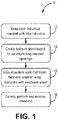
- FIG. 1 is a flowchart illustrating selected steps 12-18 of method 10, used to form a composite component.
- the component is a ceramic matrix composite (CMC) component.
- FIG. 2 is a simplified illustration of mandrel 20 used in method 10.
- FIGS. 3, 4 , 5, and 6 are simplified cross-sectional views of alternate embodiments of a fiber preform. Steps 12-18 are described below in combination with FIGS. 2-6 .
- each mandrel 20 is wrapped with at least one composite fiber sheet 22 (shown in FIGS. 3 and 5 ).
- sheet can be interchangeable with terms such as "ply” and "fabric”.
- Each sheet 22 (or 122 in FIG. 5 ) can be formed from braided or woven ceramic fibers or tows arranged in a uni- or multidirectional manner.
- Exemplary sheets 22, 122 can have 5-harness, 8-harness, plain, or twill weave patterns.
- the ceramic fibers can be formed from silicon carbide or other suitable ceramic materials.
- Each sheet 22, 122 can have a thickness ranging from 0.152 mm to 0.508 mm (0.006 inches to 0.020 inches).
- each mandrel 20 can include one or more openings 24.
- Openings 24 can be rounded (e.g., circular, elliptical, etc.), have straight sides (e.g., diamond, square, etc.) or a combination of the two. Openings 24 can further be generally uniform in size and shape, as shown in FIG. 2 , or can vary along a given mandrel 20. Most generally, openings 24 are formed at locations and in shapes selected to promote a desired fluid flow volume and patterns between open or hollow spaces in the final component defined during manufacture by the respective locations of adjacent mandrels.
- a sheet 22 can be wrapped around a respective mandrel 20 such that it at least fully circumscribes the mandrel (i.e., opposite ends of sheet 22 touch or overlap slightly). In an alternative embodiment, however, it may only be necessary to cover an area including openings 24, but otherwise not fully circumscribe the mandrel 20 with the one or more sheets 22.
- holes 26 can be formed by completely removing sections (i.e., portions lesser than the whole) of sheet 22 by, for example, cutting through the fibers of sheet 22 with a sharp tool or laser, or by using a punching tool. Each hole 26 can generally be formed to match the geometry of the underlying mandrel opening 24.
- holes 26 can be formed by pushing pin 25 (shown in FIG. 2 ) through a section of sheet 22 corresponding to an opening 24 in mandrel 20.
- pin can be interchangeable with terms such as “needle,” “rod,” “tube,” or “wire.”
- Pin 25 can be inserted into sheet 22 such that it generally does not damage (e.g., puncture or break) individual fibers, rather, fibers are pushed aside to accommodate the pin. This differs from cutting or punching through sheet 22 which breaks fibers so that a section of sheet 22 is separated and removed.
- Using a pin may be preferable if greater continuity (e.g., lack of breakage) of fibers within individual sheets 22 is desired for enhanced mechanical and/or thermal properties.
- One or more pins 25 can be used to create holes 26.
- pin(s) 25 can create a hole 26 but be removed prior to subsequent processing.
- individual pins 25 can be pushed into sheet 22 at the desired location of holes 26 and remain embedded throughout subsequent steps of method 10. The latter may prevent the fibers from moving back into the region of holes 26 during, for example, matrix formation discussed below.
- one or more pins 25 can be formed as a part of mandrel 20 (as protrusions, bumps, bosses, etc.) in a manner similar to the arrangement of openings 24. In such an embodiment, a sheet 22 can be pushed down onto the protrusions and wrapped as desired.
- mandrels 20 are brought together and aligned such that the holes 26 of the first sheet 22 on the first mandrel 20 are aligned with holes 26 on the second sheet 22 of the second mandrel 20.
- This alignment can, as in the embodiment illustrated in FIGS. 3 and 4 , be achieved when openings 24 of adjacent mandrels are aligned.
- the shaping or angle of holes 26 can result in alignment of holes 26 requiring that openings 24 of adjacent mandrels be relatively displaced or offset.
- mandrels 20 can be overwrapped by at least one additional sheet 22 which surrounds both mandrels 20 to form fiber preform 28.
- FIG. 3 is a cross-sectional view of preform 28 including a first mandrel 20 wrapped with a first sheet 22, a second mandrel 20 wrapped with a second sheet 22, and overwrapped with a third sheet 22.
- Preform 28 extends along longitudinal axis A. It should be understood that either/both mandrels 20 can be wrapped with more than one sheet 22, and the overwrap can additionally/alternatively include more than one sheet 22 based on, for example, the desired thickness of the corresponding regions of the final component. Further, although represented with varied hatching for easier visualization of the individual sheets 22, sheets 22 can be formed from the same material and/or have the same thickness, or vary in material and/or thickness. As can be seen in FIG. 3 , a pair of aligned holes 26 form a channel 30.
- FIG. 4 is an enlarged view of area A4 of FIG. 3 showing an individual channel 30.
- Such channel orientation can be achieved by forming pairs of holes 26 at the same location on the respective mandrels 20.
- channels 30 can have a generally cylindrical cross-sectional shape when each hole 26 in a respective pair has the same area as the corresponding hole 26.
- Other cross-sectional shapes e.g., frustoconical are contemplated herein.
- FIG. 5 is a cross-sectional view of alternative preform 128.
- FIG. 6 is an enlarged view of area A6 of FIG. 5 showing an individual channel 130 of preform 128.
- Preform 128 is substantially similar to preform 28, except for the shape and orientation of channels 130.
- channels 130 extend at a non-orthogonal angle with respect to axis A. More specifically, angle ⁇ is greater than 90°, and can alternatively be less than 90° in another embodiment.
- Angled channels 130 can be achieved by staggering/offsetting each hole 126 in a respective pair of holes 126.
- Channels 130 are also shown as having a frustoconical cross-sectional shape, which can be achieved by making one hole 126 in a respective pair of holes 126 larger in at least one dimension than the corresponding hole 126.
- Other cross-sectional shapes e.g., cylindrical
- Angled and/or frustoconical channels can promote directional flow (e.g., for vortex formation) to improve cooling.
- each hole 26 and/or 126 can range from 0.254 mm to 5.08 mm (0.010 inches to 0.200 inches). As used herein, size can refer to a major dimension, such as radius for circular and elliptical holes 26, 126, or length of a straight segment for shapes such as square, rectangular, diamond, etc.
- preform 28, 128 undergoes matrix formation and densification using a chemical vapor infiltration or deposition (CVI or CVD) process.
- CVI or CVD chemical vapor infiltration or deposition
- sheets 22,122 are infiltrated by reactant vapors, and a gaseous precursor deposits on the fibers.
- the matrix material can be a silicon carbide or other suitable ceramic material. Densification is carried out until the resulting CMC has reached the desired residual porosity.
- Mandrels 20, 120 can also be physically or chemically removed post-densification, as well as any pins, if used, inserted in sheets 22, 122. Removing mandrels 20, 120 and pins 25 leaves cavities and passages within the finished workpiece for cooling airflow.
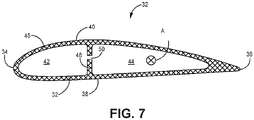
- FIG. 7 is a cross-sectional view of component 32, a CMC airfoil, formed using method 10.
- Component 32 extends longitudinally along axis A, which can be the same as the longitudinal axis of preform 28, 128.
- Component 32 includes leading edge 34, trailing edge 36, pressure side 38, and suction side 40.
- a leading edge cavity 42 is and trailing edge cavity 44 are defined by outer wall 46 and dividing wall 48.
- Each of leading edge cavity 42 and trailing edge cavity 44 represent the space at least partially occupied by mandrels 20, 120 during component preforming.
- Walls 46 and 48 are formed by the various sheets 22, 122 wrapped around mandrels 20, 120.
- any of walls 46 and 48 can have a wall thickness ranging from 0.508 mm to 1.524 mm (0.020 inches to 0.060 inches).
- Crossover channels 50 (only one is shown) in dividing wall 48 is equivalent to channels 30, 130 of preform 28, 128.
- a cooling airflow can be supplied to leading edge cavity 42 and/or trailing edge cavity 44 from an external source, and the cooling airflow can pass from the receiving cavity to the other cavity via crossover channels 50.
- Method 10 discussed above can include additional steps (inter-step or post processing) not shown in FIG. 1 .
- various post-processing steps can be performed, such as the application of one or more protective coatings, such an environmental and/or thermal barrier coatings.
- a bond coat can also be applied to facilitate bonding between the CMC and protective coating.
- Other protective coatings especially those suitable for use in a gas turbine engine environment, are contemplated herein.
- Various inter-step processes can also be performed, such as the application of a tackifier to sheets 22, 122 prior to or just after wrapping on mandrels 20. Other inter-step processes like surface preparation and cleaning are contemplated herein.
- alternative preform embodiments can include more than two mandrels to create additional cavities in component 32, as well as any combination of channels 30, 130 in a single embodiment.
- Channels can also be formed in other walls (e.g., outer wall) and structures in the composite component. It is further possible to apply the disclosed method to other types of composites (e.g., organic matrix composites) without departing from the scope of the present disclosure.
- a method of forming a ceramic matrix composite component having an internal cooling circuit includes wrapping at least a first sheet around a first mandrel, wrapping at least a second sheet around a second mandrel, creating a first plurality of holes in the first sheet corresponding to a plurality of openings in the first mandrel, creating a second plurality of holes in the second sheet corresponding to a plurality of openings in the second mandrel, aligning the first mandrel and the second mandrel such that the first plurality of holes face and are aligned with the second plurality of holes, wrapping at least a third sheet around both the first mandrel and second mandrel to form a preform, the preform comprising each of the first sheet, the second sheet, and the third sheet, and densifying the preform.
- the first sheet, second sheet, and third sheet are formed from a ceramic fiber material.
- the ceramic fiber material can include silicon carbide.
- densifying the preform can include one of a chemical vapor infiltration or chemical vapor deposition process.
- the step of creating the first plurality of holes in the first sheet and the second plurality of holes in the second sheet can include removing a plurality of sections of the first sheet using a cutting or punching technique, the plurality of sections corresponding to the plurality of openings in the first mandrel, and removing a plurality of sections of the second sheet using the cutting or punching technique, the plurality of sections corresponding to the plurality of openings in the second mandrel.
- At least one of the first plurality of holes and at least one of the second plurality of holes can have a dimension ranging from 0.254 mm to 5.08 mm (0.010 inches to 0.200 inches), and the dimension can be a diameter or a length.
- At least one of the first plurality of holes can be aligned with a corresponding one of the second plurality of holes to form a channel through an internal preform wall orthogonal to a longitudinal axis of the preform.
- At least one of the first plurality of holes can be offset from a corresponding one of the second plurality of holes to form a channel through an internal preform wall angled away from a longitudinal axis of the preform less than 90° or greater than 90°.
- the dimension of the at least one of the first plurality of holes can be smaller than the dimension of the dimension of the corresponding one of the second plurality of holes.
- the step of creating a first plurality of holes in the first sheet and a second plurality of holes in the second sheet can include inserting a pin through a plurality of sections of the first sheet corresponding to the plurality of openings in the first mandrel, and inserting a pin through a plurality of sections of the second sheet corresponding to the plurality of openings in the second mandrel.
- inserting the pin through the plurality of sections of the first sheet and the second sheet can push fibers of each of the first sheet and the second sheet apart at a location of the pin.
- At least one of the first plurality of holes and at least one of the second plurality of holes can have a dimension ranging from 0.254 mm to 5.08 mm (0.010 inches to 0.200 inches), and the dimension can be a diameter or a length.
- Any of the above methods can further include removing the first mandrel and the second mandrel from the preform.
- a ceramic matrix composite airfoil can include an outer wall, a dividing wall extending between the outer wall, at least a first cavity and a second cavity defined by the outer wall and the dividing wall, the first and second cavities extending between an inner diameter of the airfoil and an outer diameter of the airfoil, and a plurality of crossover channels disposed within the dividing wall and fluidly connecting the first and second cavities.
- the dividing wall includes a first sheet of ceramic fiber material surrounding the first cavity, and a second sheet of ceramic fiber material surrounding the second cavity
- the outer wall includes the first sheet of ceramic fiber material, the second sheet of ceramic fiber material, and a third sheet of ceramic fiber material surrounding the first and second sheets of ceramic fiber material.
- the ceramic fiber material can include silicon carbide.
- a thickness of one of the outer wall and the dividing wall can range from 0.508 mm to 1.524 mm (0.020 inches to 0.060 inches).
- At least one of the plurality of crossover channels can be oriented orthogonal to a longitudinal axis of the airfoil.
- At least one of the plurality of crossover channels can be angled away from a longitudinal axis of the preform less than 90° or greater than 90°.
- At least one of the plurality of crossover channels can have a dimension ranging from 0.254 mm to 5.08 mm (0.010 inches to 0.200 inches), and the dimension can be a diameter or a length.
- At least one of the plurality of crossover channels can have one of a cylindrical and frustoconical cross-sectional shape.
- one of the at least two cavities can be a leading edge cavity.
Landscapes
- Engineering & Computer Science (AREA)
- Chemical & Material Sciences (AREA)
- Mechanical Engineering (AREA)
- Materials Engineering (AREA)
- General Engineering & Computer Science (AREA)
- Ceramic Engineering (AREA)
- Manufacturing & Machinery (AREA)
- Composite Materials (AREA)
- Structural Engineering (AREA)
- Organic Chemistry (AREA)
- Chemical Kinetics & Catalysis (AREA)
- Turbine Rotor Nozzle Sealing (AREA)
Abstract
Description
- The present invention relates to the fabrication of composite components, and more particularly, to a ceramic matrix composite having improved properties for operating in gas turbine engines.
- Ceramic matrix composite components, such as those formed of silicon carbide, are commonly used in high-temperature environments because they can withstand temperatures up to 2500°F. Such components can still benefit from additional cooling to prevent component degradation. One way to provide additional cooling is through the incorporation of internal cooling channels into the component. The structure of many composite components can make adding such features somewhat difficult when using traditional fabrication processes.
- A method of forming a ceramic matrix composite component having an internal cooling circuit includes wrapping at least a first sheet around a first mandrel, wrapping at least a second sheet around a second mandrel, creating a first plurality of holes in the first sheet corresponding to a plurality of openings in the first mandrel, creating a second plurality of holes in the second sheet corresponding to a plurality of openings in the second mandrel, aligning the first mandrel and the second mandrel such that the first plurality of holes face and are aligned with the second plurality of holes, wrapping at least a third sheet around both the first mandrel and second mandrel to form a preform, the preform comprising each of the first sheet, the second sheet, and the third sheet, and densifying the preform. The first sheet, second sheet, and third sheet are formed from a ceramic fiber material.
- A ceramic matrix composite airfoil can include an outer wall, a dividing wall extending between the outer wall, at least a first cavity and a second cavity defined by the outer wall and the dividing wall, the first and second cavities extending between an inner diameter of the airfoil and an outer diameter of the airfoil, and a plurality of crossover channels disposed within the dividing wall and fluidly connecting the first and second cavities. The dividing wall includes a first sheet of ceramic fiber material surrounding the first cavity, and a second sheet of ceramic fiber material surrounding the second cavity, and the outer wall includes the first sheet of ceramic fiber material, the second sheet of ceramic fiber material, and a third sheet of ceramic fiber material surrounding the first and second sheets of ceramic fiber material.
-
-
FIG. 1 is a flow chart illustrating steps of a method of forming an internally cooled composite component. -
FIG. 2 is a simplified perspective view of a mandrel used to form the composite component. -
FIG. 3 is a simplified cross-sectional view of a composite preform structure with channels, indicating area A4. -
FIG. 4 is a close-up cross-sectional view of area A4 ofFIG. 3 . -
FIG. 5 is a simplified cross-sectional view of an alternative composite preform structure with channels, indicating area A6. -
FIG. 6 is a close-up cross-sectional view of area A6 ofFIG. 5 . -
FIG. 7 is a cross-sectional view of a composite airfoil formed using the method ofFIG. 1 . - While the above-identified figures set forth one or more embodiments of the present disclosure, other embodiments are also contemplated, as noted in the discussion. In all cases, this disclosure presents the invention by way of representation and not limitation. It should be understood that numerous other modifications and embodiments can be devised by those skilled in the art, which fall within the scope and spirit of the principles of the invention. The figures may not be drawn to scale, and applications and embodiments of the present invention may include features and components not specifically shown in the drawings.
- This disclosure presents composite component with internal, fluidly-connected cavities, and a method of forming that composite component. The method includes wrapping multiple mandrels each with at least one fiber sheet. Each mandrel has openings or cut-outs that can serve as a template for creating corresponding holes in these fiber sheets. holes can be formed by removal of material (e.g., cutting or punching an opening in the sheet) or by pushing a pin through the thickness of the sheet and into the mandrel opening. Two wrapped mandrels can be placed together and aligned such that the holes in each sheet face and are aligned with one another. The mandrels are then overwrapped with at least one further sheet securing the wrapped mandrels in place. The resulting preform structure can undergo matrix formation and mandrel removal to become a composite component with elongate cavities fluidly connected at least in part by passages formed by the aligned holes within the fiber sheets.
-
FIG. 1 is a flowchart illustrating selected steps 12-18 ofmethod 10, used to form a composite component. In an exemplary embodiment, the component is a ceramic matrix composite (CMC) component.FIG. 2 is a simplified illustration ofmandrel 20 used inmethod 10.FIGS. 3, 4 ,5, and 6 are simplified cross-sectional views of alternate embodiments of a fiber preform. Steps 12-18 are described below in combination withFIGS. 2-6 . - At
step 12, eachmandrel 20 is wrapped with at least one composite fiber sheet 22 (shown inFIGS. 3 and5 ). As used herein, the term "sheet" can be interchangeable with terms such as "ply" and "fabric". Each sheet 22 (or 122 inFIG. 5 ) can be formed from braided or woven ceramic fibers or tows arranged in a uni- or multidirectional manner.Exemplary sheets sheet - As shown in
FIG. 2 , eachmandrel 20 can include one ormore openings 24.Openings 24 can be rounded (e.g., circular, elliptical, etc.), have straight sides (e.g., diamond, square, etc.) or a combination of the two.Openings 24 can further be generally uniform in size and shape, as shown inFIG. 2 , or can vary along a givenmandrel 20. Most generally,openings 24 are formed at locations and in shapes selected to promote a desired fluid flow volume and patterns between open or hollow spaces in the final component defined during manufacture by the respective locations of adjacent mandrels. Asheet 22 can be wrapped around arespective mandrel 20 such that it at least fully circumscribes the mandrel (i.e., opposite ends ofsheet 22 touch or overlap slightly). In an alternative embodiment, however, it may only be necessary to cover anarea including openings 24, but otherwise not fully circumscribe themandrel 20 with the one ormore sheets 22. - At
step 14, and oncesheet 22 is wrapped around or otherwise secured tomandrel 20, sections ofsheet 22 corresponding to theunderlying openings 24 ofmandrel 20 are manipulated to formholes 26. In one embodiment,holes 26 can be formed by completely removing sections (i.e., portions lesser than the whole) ofsheet 22 by, for example, cutting through the fibers ofsheet 22 with a sharp tool or laser, or by using a punching tool. Eachhole 26 can generally be formed to match the geometry of the underlying mandrel opening 24. - In an alternative embodiment,
holes 26 can be formed by pushing pin 25 (shown inFIG. 2 ) through a section ofsheet 22 corresponding to anopening 24 inmandrel 20. As used herein, the term "pin" can be interchangeable with terms such as "needle," "rod," "tube," or "wire."Pin 25 can be inserted intosheet 22 such that it generally does not damage (e.g., puncture or break) individual fibers, rather, fibers are pushed aside to accommodate the pin. This differs from cutting or punching throughsheet 22 which breaks fibers so that a section ofsheet 22 is separated and removed. Using a pin may be preferable if greater continuity (e.g., lack of breakage) of fibers withinindividual sheets 22 is desired for enhanced mechanical and/or thermal properties. One ormore pins 25 can be used to createholes 26. In some cases, pin(s) 25 can create ahole 26 but be removed prior to subsequent processing. In other cases, however,individual pins 25 can be pushed intosheet 22 at the desired location ofholes 26 and remain embedded throughout subsequent steps ofmethod 10. The latter may prevent the fibers from moving back into the region ofholes 26 during, for example, matrix formation discussed below. In another alternative embodiment, one ormore pins 25 can be formed as a part of mandrel 20 (as protrusions, bumps, bosses, etc.) in a manner similar to the arrangement ofopenings 24. In such an embodiment, asheet 22 can be pushed down onto the protrusions and wrapped as desired. - At
step 16, and once the desiredholes 26 are formed in eachsheet 22 of eachmandrel 20,mandrels 20 are brought together and aligned such that theholes 26 of thefirst sheet 22 on thefirst mandrel 20 are aligned withholes 26 on thesecond sheet 22 of thesecond mandrel 20. This alignment can, as in the embodiment illustrated inFIGS. 3 and 4 , be achieved whenopenings 24 of adjacent mandrels are aligned. In other embodiments, as illustrated inFIGS. 5 and 6 , the shaping or angle ofholes 26 can result in alignment ofholes 26 requiring thatopenings 24 of adjacent mandrels be relatively displaced or offset. Once aligned,mandrels 20 can be overwrapped by at least oneadditional sheet 22 which surrounds bothmandrels 20 to formfiber preform 28. -
FIG. 3 is a cross-sectional view ofpreform 28 including afirst mandrel 20 wrapped with afirst sheet 22, asecond mandrel 20 wrapped with asecond sheet 22, and overwrapped with athird sheet 22.Preform 28 extends along longitudinal axis A. It should be understood that either/bothmandrels 20 can be wrapped with more than onesheet 22, and the overwrap can additionally/alternatively include more than onesheet 22 based on, for example, the desired thickness of the corresponding regions of the final component. Further, although represented with varied hatching for easier visualization of theindividual sheets 22,sheets 22 can be formed from the same material and/or have the same thickness, or vary in material and/or thickness. As can be seen inFIG. 3 , a pair of alignedholes 26 form achannel 30. -
FIG. 4 is an enlarged view of area A4 ofFIG. 3 showing anindividual channel 30. With reference toFIGS. 3 and 4 , holes 26 are aligned such thatchannel 30 is generally orthogonal (i.e., angle Θ = 90°) to axis A. Such channel orientation can be achieved by forming pairs ofholes 26 at the same location on therespective mandrels 20. Additionally,channels 30 can have a generally cylindrical cross-sectional shape when eachhole 26 in a respective pair has the same area as the correspondinghole 26. Other cross-sectional shapes (e.g., frustoconical) are contemplated herein. -
FIG. 5 is a cross-sectional view ofalternative preform 128.FIG. 6 is an enlarged view of area A6 ofFIG. 5 showing anindividual channel 130 ofpreform 128.Preform 128 is substantially similar to preform 28, except for the shape and orientation ofchannels 130. As shown,channels 130 extend at a non-orthogonal angle with respect to axis A. More specifically, angle Θ is greater than 90°, and can alternatively be less than 90° in another embodiment.Angled channels 130 can be achieved by staggering/offsetting eachhole 126 in a respective pair ofholes 126.Channels 130 are also shown as having a frustoconical cross-sectional shape, which can be achieved by making onehole 126 in a respective pair ofholes 126 larger in at least one dimension than thecorresponding hole 126. Other cross-sectional shapes (e.g., cylindrical) are contemplated herein. Angled and/or frustoconical channels can promote directional flow (e.g., for vortex formation) to improve cooling. - The size of each
hole 26 and/or 126 can range from 0.254 mm to 5.08 mm (0.010 inches to 0.200 inches). As used herein, size can refer to a major dimension, such as radius for circular andelliptical holes - At
step 18,preform Mandrels sheets mandrels -
FIG. 7 is a cross-sectional view ofcomponent 32, a CMC airfoil, formed usingmethod 10.Component 32 extends longitudinally along axis A, which can be the same as the longitudinal axis ofpreform Component 32 includes leadingedge 34, trailingedge 36,pressure side 38, andsuction side 40. Aleading edge cavity 42 is and trailingedge cavity 44 are defined byouter wall 46 and dividingwall 48. Each of leadingedge cavity 42 and trailingedge cavity 44 represent the space at least partially occupied bymandrels Walls various sheets mandrels walls wall 48 is equivalent tochannels preform component 32, a cooling airflow can be supplied to leadingedge cavity 42 and/or trailingedge cavity 44 from an external source, and the cooling airflow can pass from the receiving cavity to the other cavity viacrossover channels 50. -
Method 10 discussed above can include additional steps (inter-step or post processing) not shown inFIG. 1 . For example, afterstep 18, various post-processing steps can be performed, such as the application of one or more protective coatings, such an environmental and/or thermal barrier coatings. A bond coat can also be applied to facilitate bonding between the CMC and protective coating. Other protective coatings, especially those suitable for use in a gas turbine engine environment, are contemplated herein. Various inter-step processes can also be performed, such as the application of a tackifier tosheets mandrels 20. Other inter-step processes like surface preparation and cleaning are contemplated herein. - It should also be understood that alternative preform embodiments can include more than two mandrels to create additional cavities in
component 32, as well as any combination ofchannels - The following are non-exclusive descriptions of possible embodiments of the present invention.
- A method of forming a ceramic matrix composite component having an internal cooling circuit includes wrapping at least a first sheet around a first mandrel, wrapping at least a second sheet around a second mandrel, creating a first plurality of holes in the first sheet corresponding to a plurality of openings in the first mandrel, creating a second plurality of holes in the second sheet corresponding to a plurality of openings in the second mandrel, aligning the first mandrel and the second mandrel such that the first plurality of holes face and are aligned with the second plurality of holes, wrapping at least a third sheet around both the first mandrel and second mandrel to form a preform, the preform comprising each of the first sheet, the second sheet, and the third sheet, and densifying the preform. The first sheet, second sheet, and third sheet are formed from a ceramic fiber material.
- The method of the preceding paragraph can optionally include, additionally and/or alternatively, any one or more of the following features, configurations and/or additional components:
In the above method, the ceramic fiber material can include silicon carbide. - In any of the above methods, densifying the preform can include one of a chemical vapor infiltration or chemical vapor deposition process.
- In any of the above methods, the step of creating the first plurality of holes in the first sheet and the second plurality of holes in the second sheet can include removing a plurality of sections of the first sheet using a cutting or punching technique, the plurality of sections corresponding to the plurality of openings in the first mandrel, and removing a plurality of sections of the second sheet using the cutting or punching technique, the plurality of sections corresponding to the plurality of openings in the second mandrel.
- In any of the above methods, at least one of the first plurality of holes and at least one of the second plurality of holes can have a dimension ranging from 0.254 mm to 5.08 mm (0.010 inches to 0.200 inches), and the dimension can be a diameter or a length.
- In any of the above methods, at least one of the first plurality of holes can be aligned with a corresponding one of the second plurality of holes to form a channel through an internal preform wall orthogonal to a longitudinal axis of the preform.
- In any of the above methods, at least one of the first plurality of holes can be offset from a corresponding one of the second plurality of holes to form a channel through an internal preform wall angled away from a longitudinal axis of the preform less than 90° or greater than 90°.
- In any of the above methods, the dimension of the at least one of the first plurality of holes can be smaller than the dimension of the dimension of the corresponding one of the second plurality of holes.
- In any of the above methods, the step of creating a first plurality of holes in the first sheet and a second plurality of holes in the second sheet can include inserting a pin through a plurality of sections of the first sheet corresponding to the plurality of openings in the first mandrel, and inserting a pin through a plurality of sections of the second sheet corresponding to the plurality of openings in the second mandrel.
- In any of the above methods, inserting the pin through the plurality of sections of the first sheet and the second sheet can push fibers of each of the first sheet and the second sheet apart at a location of the pin.
- In any of the above methods, at least one of the first plurality of holes and at least one of the second plurality of holes can have a dimension ranging from 0.254 mm to 5.08 mm (0.010 inches to 0.200 inches), and the dimension can be a diameter or a length.
- Any of the above methods can further include removing the first mandrel and the second mandrel from the preform.
- A ceramic matrix composite airfoil can include an outer wall, a dividing wall extending between the outer wall, at least a first cavity and a second cavity defined by the outer wall and the dividing wall, the first and second cavities extending between an inner diameter of the airfoil and an outer diameter of the airfoil, and a plurality of crossover channels disposed within the dividing wall and fluidly connecting the first and second cavities. The dividing wall includes a first sheet of ceramic fiber material surrounding the first cavity, and a second sheet of ceramic fiber material surrounding the second cavity, and the outer wall includes the first sheet of ceramic fiber material, the second sheet of ceramic fiber material, and a third sheet of ceramic fiber material surrounding the first and second sheets of ceramic fiber material.
- The airfoil of the preceding paragraph can optionally include, additionally and/or alternatively, any one or more of the following features, configurations and/or additional components:
In the above airfoil, the ceramic fiber material can include silicon carbide. - In any of the above airfoils, a thickness of one of the outer wall and the dividing wall can range from 0.508 mm to 1.524 mm (0.020 inches to 0.060 inches).
- In any of the above airfoils, at least one of the plurality of crossover channels can be oriented orthogonal to a longitudinal axis of the airfoil.
- In any of the above airfoils, at least one of the plurality of crossover channels can be angled away from a longitudinal axis of the preform less than 90° or greater than 90°.
- In any of the above airfoils, at least one of the plurality of crossover channels can have a dimension ranging from 0.254 mm to 5.08 mm (0.010 inches to 0.200 inches), and the dimension can be a diameter or a length.
- In any of the above airfoils, at least one of the plurality of crossover channels can have one of a cylindrical and frustoconical cross-sectional shape.
- In any of the above airfoils, one of the at least two cavities can be a leading edge cavity.
- While the invention has been described with reference to an exemplary embodiment(s), it will be understood by those skilled in the art that various changes may be made and equivalents may be substituted for elements thereof without departing from the scope of the invention. In addition, many modifications may be made to adapt a particular situation or material to the teachings of the invention without departing from the essential scope thereof. Therefore, it is intended that the invention not be limited to the particular embodiment(s) disclosed, but that the invention will include all embodiments falling within the scope of the appended claims.
Claims (15)
- A method of forming a ceramic matrix composite component having an internal cooling circuit, the method comprising:wrapping at least a first sheet (22; 122) around a first mandrel (20; 120);wrapping at least a second sheet (22; 122) around a second mandrel (20; 120);creating a first plurality of holes (26; 126) in the first sheet (22; 122) corresponding to a plurality of openings (24; 124) in the first mandrel (20; 120);creating a second plurality of holes (26; 126) in the second sheet (22; 122) corresponding to a plurality of openings (24; 124) in the second mandrel (20; 120);aligning the first mandrel (20; 120) and the second mandrel (20; 120) such that the first plurality of holes (26; 126) face and are aligned with the second plurality of holes (26; 126);wrapping at least a third sheet (22; 122) around both the first mandrel (20; 120) and second mandrel (20; 120) to form a preform (28; 128), the preform (28; 128) comprising each of the first sheet (22; 122), the second sheet (22; 122), and the third sheet (22; 122); anddensifying the preform (28; 128);wherein the first sheet (22; 122), second sheet (22; 122), and third sheet (22; 122) are formed from a ceramic fiber material.
- The method of claim 1, wherein densifying the preform (28; 128) comprises one of a chemical vapor infiltration (CVI) or chemical vapor deposition process (CVD).
- The method of claim 1 or 2, wherein the step of creating the first plurality of holes (26; 126) in the first sheet (22; 122) and the second plurality of holes (26; 126) in the second sheet (22; 122) comprises:removing a plurality of sections of the first sheet (22; 122) using a cutting or punching technique, the plurality of sections corresponding to the plurality of openings (24; 124) in the first mandrel (20; 120); andremoving a plurality of sections of the second sheet (22; 122) using the cutting or punching technique, the plurality of sections corresponding to the plurality of openings (24; 124) in the second mandrel (20; 120).
- The method of any preceding claim, wherein:at least one of the first plurality of holes (26; 126) and at least one of the second plurality of holes (26; 126) has a dimension ranging from 0.254 mm to 5.08 mm (0.010 inches to 0.200 inches), and wherein the dimension is a diameter or a length; and, optionally,the dimension of the at least one of the first plurality of holes (26; 126) is smaller than the dimension of the dimension of the corresponding one of the second plurality of holes (26, 126).
- The method of any preceding claim, wherein:at least one of the first plurality of holes (26) is aligned with a corresponding one of the second plurality of holes (26) to form a channel (30) through an internal preform (28) wall orthogonal to a longitudinal axis (A) of the preform (28); orat least one of the first plurality of holes (126) is offset from a corresponding one of the second plurality of holes (126) to form a channel (130) through an internal preform (128) wall angled away from a longitudinal axis (A) of the preform (128) less than 90° or greater than 90°.
- The method of any preceding claim, wherein the step of creating a first plurality of holes (26; 126) in the first sheet (22; 122) and a second plurality of holes (26; 126) in the second sheet (22; 122) comprises:inserting a pin (25) through a plurality of sections of the first sheet (22; 122) corresponding to the plurality of openings (24; 124) in the first mandrel (20; 120); andinserting a pin (25) through a plurality of sections of the second sheet (22; 122) corresponding to the plurality of openings (24; 124) in the second mandrel (20; 120).
- The method of claim 6, wherein inserting the pin (25) through the plurality of sections of the first sheet (22; 122) and the second sheet (22; 122) pushes fibers of each of the first sheet (22; 122) and the second sheet (22; 122) apart at a location of the pin (25).
- The method of any preceding claim further comprising:
removing the first mandrel (20; 120) and the second mandrel (20; 120) from the preform (28; 128). - A ceramic matrix composite airfoil (32) comprising:an outer wall (46);a dividing wall (48) extending between the outer wall (46);at least a first cavity (42) and a second cavity (44) defined by the outer wall (46) and the dividing wall (48), the first and second cavities (42, 44) extending between an inner diameter of the airfoil (32) and an outer diameter of the airfoil (32); anda plurality of crossover channels (50) disposed within the dividing wall (48) and fluidly connecting the first and second cavities (42, 44);wherein the dividing wall (48) comprises a first sheet (22; 122) of ceramic fiber material surrounding the first cavity (42), and a second sheet (22; 122) of ceramic fiber material surrounding the second cavity (44); andwherein the outer wall (46) comprises the first sheet (22; 122) of ceramic fiber material, the second sheet (22; 122) of ceramic fiber material, and a third sheet (22; 122) of ceramic fiber material surrounding the first and second sheets (22; 122) of ceramic fiber material.
- The airfoil of claim 9, wherein a thickness of one of the outer wall (46) and the dividing wall (48) ranges from 0.508 mm to 1.524 mm (0.020 inches to 0.060 inches).
- The airfoil of claim 9 or 10, wherein:at least one of the plurality of crossover channels (50) is oriented orthogonal to a longitudinal axis (A) of the airfoil (32); orat least one of the plurality of crossover channels (50) is angled away from a longitudinal axis (A) of the preform (28; 128) less than 90° or greater than 90°.
- The airfoil of claim 9, 10 or 11, wherein at least one of the plurality of crossover channels (50) has a dimension ranging from 0.254 mm to 5.08 mm (0.010 inches to 0.200 inches), and wherein the dimension is a diameter or a length.
- The airfoil of any of claims 9 to 12, wherein at least one of the plurality of crossover channels (50) has one of a cylindrical and frustoconical cross-sectional shape.
- The airfoil of any of claims 9 to 13, wherein one of the at least two cavities (42, 44) is a leading edge cavity (42).
- The method or airfoil of any preceding claim, wherein the ceramic fiber material comprises silicon carbide.
Applications Claiming Priority (1)
| Application Number | Priority Date | Filing Date | Title |
|---|---|---|---|
| US17/339,198 US11608748B2 (en) | 2021-06-04 | 2021-06-04 | Preform crossovers for composite airfoils |
Publications (2)
| Publication Number | Publication Date |
|---|---|
| EP4098417A1 true EP4098417A1 (en) | 2022-12-07 |
| EP4098417B1 EP4098417B1 (en) | 2024-10-23 |
Family
ID=81346659
Family Applications (1)
| Application Number | Title | Priority Date | Filing Date |
|---|---|---|---|
| EP22169258.5A Active EP4098417B1 (en) | 2021-06-04 | 2022-04-21 | Method of forming a ceramic matrix composite component having an internal cooling circuit |
Country Status (2)
| Country | Link |
|---|---|
| US (1) | US11608748B2 (en) |
| EP (1) | EP4098417B1 (en) |
Families Citing this family (3)
| Publication number | Priority date | Publication date | Assignee | Title |
|---|---|---|---|---|
| US12565451B2 (en) | 2023-08-21 | 2026-03-03 | Rtx Corporation | Multi-mandrel braiding process |
| US12552085B2 (en) | 2023-10-20 | 2026-02-17 | Rtx Corporation | Z-channeling into a preform via needle perforation in a stand-alone tool |
| US12473236B2 (en) * | 2023-10-20 | 2025-11-18 | Rtx Corporation | Internal tooling configuration for the creation of z-channels in woven ceramic matrix composite preforms |
Citations (2)
| Publication number | Priority date | Publication date | Assignee | Title |
|---|---|---|---|---|
| EP2787174A2 (en) * | 2013-04-02 | 2014-10-08 | Honeywell International Inc. | Gas turbine engines with turbine airfoil cooling |
| EP3508316A2 (en) * | 2018-01-05 | 2019-07-10 | United Technologies Corporation | Needled ceramic matrix composite cooling passages |
Family Cites Families (17)
| Publication number | Priority date | Publication date | Assignee | Title |
|---|---|---|---|---|
| US5383566A (en) * | 1993-08-05 | 1995-01-24 | Edo Corporation, Fiber Science Division | Dual-chamber composite pressure vessel and method of fabrication thereof |
| US6884030B2 (en) * | 2002-12-20 | 2005-04-26 | General Electric Company | Methods and apparatus for securing multi-piece nozzle assemblies |
| US7600979B2 (en) * | 2006-11-28 | 2009-10-13 | General Electric Company | CMC articles having small complex features |
| ES2442873T3 (en) * | 2008-03-31 | 2014-02-14 | Alstom Technology Ltd | Aerodynamic gas turbine profile |
| US10408084B2 (en) * | 2015-03-02 | 2019-09-10 | Rolls-Royce North American Technologies Inc. | Vane assembly for a gas turbine engine |
| US10465533B2 (en) | 2015-10-08 | 2019-11-05 | General Electric Company | Ceramic matrix composite component and process of producing a ceramic matrix composite component |
| US10260358B2 (en) | 2015-10-29 | 2019-04-16 | General Electric Company | Ceramic matrix composite component and process of producing a ceramic matrix composite component |
| US10458251B2 (en) * | 2016-04-15 | 2019-10-29 | General Electric Company | Airfoil cooling using non-line of sight holes |
| US10207471B2 (en) * | 2016-05-04 | 2019-02-19 | General Electric Company | Perforated ceramic matrix composite ply, ceramic matrix composite article, and method for forming ceramic matrix composite article |
| EP3381668B1 (en) * | 2017-03-31 | 2020-12-09 | Crompton Technology Group Limited | Composite shaft |
| US10370976B2 (en) * | 2017-08-17 | 2019-08-06 | United Technologies Corporation | Directional cooling arrangement for airfoils |
| US10934854B2 (en) | 2018-09-11 | 2021-03-02 | General Electric Company | CMC component cooling cavities |
| US10724387B2 (en) * | 2018-11-08 | 2020-07-28 | Raytheon Technologies Corporation | Continuation of a shear tube through a vane platform for structural support |
| US11098608B2 (en) * | 2019-03-13 | 2021-08-24 | Raytheon Technologies Corporation | CMC BOAS with internal support structure |
| US11384028B2 (en) | 2019-05-03 | 2022-07-12 | Raytheon Technologies Corporation | Internal cooling circuits for CMC and method of manufacture |
| US11286792B2 (en) * | 2019-07-30 | 2022-03-29 | Rolls-Royce Plc | Ceramic matrix composite vane with cooling holes and methods of making the same |
| US11180999B2 (en) * | 2019-12-20 | 2021-11-23 | General Electric Company | Ceramic matrix composite component and method of producing a ceramic matrix composite component |
-
2021
- 2021-06-04 US US17/339,198 patent/US11608748B2/en active Active
-
2022
- 2022-04-21 EP EP22169258.5A patent/EP4098417B1/en active Active
Patent Citations (2)
| Publication number | Priority date | Publication date | Assignee | Title |
|---|---|---|---|---|
| EP2787174A2 (en) * | 2013-04-02 | 2014-10-08 | Honeywell International Inc. | Gas turbine engines with turbine airfoil cooling |
| EP3508316A2 (en) * | 2018-01-05 | 2019-07-10 | United Technologies Corporation | Needled ceramic matrix composite cooling passages |
Also Published As
| Publication number | Publication date |
|---|---|
| US11608748B2 (en) | 2023-03-21 |
| EP4098417B1 (en) | 2024-10-23 |
| US20220389822A1 (en) | 2022-12-08 |
Similar Documents
| Publication | Publication Date | Title |
|---|---|---|
| EP4098417A1 (en) | Preform crossovers for composite airfoils | |
| CN102782256B (en) | Turbine engine blade made of composite material and method of manufacturing same | |
| US12528228B2 (en) | Methods for complex geometry mandrel removal of ceramic matrix composite components | |
| JP5599865B2 (en) | Method for manufacturing turbomachine blades made from composite materials | |
| US9802869B2 (en) | Method for manufacturing an oxide/oxide composite material turbomachine blade provided with internal channels | |
| CA2799707C (en) | Turbomachine blade having complementary even/odd geometry and its manufacturing method | |
| US12157708B2 (en) | Method for creating cooling holes in a CMC laminate | |
| CA2799706C (en) | Turbomachine blade having complementary asymmetrical geometry | |
| US20110311368A1 (en) | Composite material turbine engine vane, and method for manufacturing same | |
| EP1768893A2 (en) | Ceramic matrix composite airfoil trailing edge arrangement | |
| CN105593417B (en) | Fibre structure with the floating silk of packet | |
| EP4286127B1 (en) | A fibrous preform comprising a plurality of hourglass-shaped voids | |
| EP3760604B1 (en) | Method of forming cooling channels in a ceramic matrix composite component | |
| EP4357114A1 (en) | Floating tooling assembly for chemical vapor infiltration | |
| US11280200B2 (en) | Gas turbine blade | |
| EP4047183B1 (en) | Bifurcating layup for airfoil rib, methods of manufacture thereof and articles comprising the same | |
| US12473236B2 (en) | Internal tooling configuration for the creation of z-channels in woven ceramic matrix composite preforms | |
| EP4345185A1 (en) | Minimization of chemical vapor infiltration tooling hole length through counterbores | |
| EP4527581A1 (en) | Deformable mandrel made of auxetic material and method of fabricating a ceramic matrix composite component using the same | |
| EP4549146A1 (en) | Pre-shaped space fillers for small cross section features | |
| EP4523895A2 (en) | Multi-mandrel braiding process |
Legal Events
| Date | Code | Title | Description |
|---|---|---|---|
| PUAI | Public reference made under article 153(3) epc to a published international application that has entered the european phase |
Free format text: ORIGINAL CODE: 0009012 |
|
| STAA | Information on the status of an ep patent application or granted ep patent |
Free format text: STATUS: THE APPLICATION HAS BEEN PUBLISHED |
|
| AK | Designated contracting states |
Kind code of ref document: A1 Designated state(s): AL AT BE BG CH CY CZ DE DK EE ES FI FR GB GR HR HU IE IS IT LI LT LU LV MC MK MT NL NO PL PT RO RS SE SI SK SM TR |
|
| STAA | Information on the status of an ep patent application or granted ep patent |
Free format text: STATUS: REQUEST FOR EXAMINATION WAS MADE |
|
| 17P | Request for examination filed |
Effective date: 20230607 |
|
| RBV | Designated contracting states (corrected) |
Designated state(s): AL AT BE BG CH CY CZ DE DK EE ES FI FR GB GR HR HU IE IS IT LI LT LU LV MC MK MT NL NO PL PT RO RS SE SI SK SM TR |
|
| RAP3 | Party data changed (applicant data changed or rights of an application transferred) |
Owner name: RTX CORPORATION |
|
| GRAP | Despatch of communication of intention to grant a patent |
Free format text: ORIGINAL CODE: EPIDOSNIGR1 |
|
| STAA | Information on the status of an ep patent application or granted ep patent |
Free format text: STATUS: GRANT OF PATENT IS INTENDED |
|
| RIC1 | Information provided on ipc code assigned before grant |
Ipc: F01D 5/28 20060101ALI20240418BHEP Ipc: F01D 5/18 20060101ALI20240418BHEP Ipc: C04B 35/80 20060101ALI20240418BHEP Ipc: C04B 35/76 20060101ALI20240418BHEP Ipc: C04B 35/565 20060101ALI20240418BHEP Ipc: B28B 23/00 20060101ALI20240418BHEP Ipc: B28B 21/70 20060101ALI20240418BHEP Ipc: B28B 21/48 20060101ALI20240418BHEP Ipc: B28B 19/00 20060101ALI20240418BHEP Ipc: B28B 11/00 20060101ALI20240418BHEP Ipc: B28B 1/48 20060101ALI20240418BHEP Ipc: B28B 1/40 20060101AFI20240418BHEP |
|
| INTG | Intention to grant announced |
Effective date: 20240517 |
|
| GRAS | Grant fee paid |
Free format text: ORIGINAL CODE: EPIDOSNIGR3 |
|
| GRAA | (expected) grant |
Free format text: ORIGINAL CODE: 0009210 |
|
| STAA | Information on the status of an ep patent application or granted ep patent |
Free format text: STATUS: THE PATENT HAS BEEN GRANTED |
|
| AK | Designated contracting states |
Kind code of ref document: B1 Designated state(s): AL AT BE BG CH CY CZ DE DK EE ES FI FR GB GR HR HU IE IS IT LI LT LU LV MC MK MT NL NO PL PT RO RS SE SI SK SM TR |
|
| REG | Reference to a national code |
Ref country code: GB Ref legal event code: FG4D |
|
| REG | Reference to a national code |
Ref country code: CH Ref legal event code: EP |
|
| REG | Reference to a national code |
Ref country code: DE Ref legal event code: R096 Ref document number: 602022006971 Country of ref document: DE |
|
| REG | Reference to a national code |
Ref country code: IE Ref legal event code: FG4D |
|
| REG | Reference to a national code |
Ref country code: LT Ref legal event code: MG9D |
|
| REG | Reference to a national code |
Ref country code: NL Ref legal event code: MP Effective date: 20241023 |
|
| REG | Reference to a national code |
Ref country code: AT Ref legal event code: MK05 Ref document number: 1734486 Country of ref document: AT Kind code of ref document: T Effective date: 20241023 |
|
| PG25 | Lapsed in a contracting state [announced via postgrant information from national office to epo] |
Ref country code: NL Free format text: LAPSE BECAUSE OF FAILURE TO SUBMIT A TRANSLATION OF THE DESCRIPTION OR TO PAY THE FEE WITHIN THE PRESCRIBED TIME-LIMIT Effective date: 20241023 |
|
| PG25 | Lapsed in a contracting state [announced via postgrant information from national office to epo] |
Ref country code: NL Free format text: LAPSE BECAUSE OF FAILURE TO SUBMIT A TRANSLATION OF THE DESCRIPTION OR TO PAY THE FEE WITHIN THE PRESCRIBED TIME-LIMIT Effective date: 20241023 |
|
| PG25 | Lapsed in a contracting state [announced via postgrant information from national office to epo] |
Ref country code: IS Free format text: LAPSE BECAUSE OF FAILURE TO SUBMIT A TRANSLATION OF THE DESCRIPTION OR TO PAY THE FEE WITHIN THE PRESCRIBED TIME-LIMIT Effective date: 20250223 Ref country code: PT Free format text: LAPSE BECAUSE OF FAILURE TO SUBMIT A TRANSLATION OF THE DESCRIPTION OR TO PAY THE FEE WITHIN THE PRESCRIBED TIME-LIMIT Effective date: 20250224 Ref country code: HR Free format text: LAPSE BECAUSE OF FAILURE TO SUBMIT A TRANSLATION OF THE DESCRIPTION OR TO PAY THE FEE WITHIN THE PRESCRIBED TIME-LIMIT Effective date: 20241023 |
|
| PG25 | Lapsed in a contracting state [announced via postgrant information from national office to epo] |
Ref country code: FI Free format text: LAPSE BECAUSE OF FAILURE TO SUBMIT A TRANSLATION OF THE DESCRIPTION OR TO PAY THE FEE WITHIN THE PRESCRIBED TIME-LIMIT Effective date: 20241023 |
|
| PG25 | Lapsed in a contracting state [announced via postgrant information from national office to epo] |
Ref country code: BG Free format text: LAPSE BECAUSE OF FAILURE TO SUBMIT A TRANSLATION OF THE DESCRIPTION OR TO PAY THE FEE WITHIN THE PRESCRIBED TIME-LIMIT Effective date: 20241023 |
|
| PG25 | Lapsed in a contracting state [announced via postgrant information from national office to epo] |
Ref country code: ES Free format text: LAPSE BECAUSE OF FAILURE TO SUBMIT A TRANSLATION OF THE DESCRIPTION OR TO PAY THE FEE WITHIN THE PRESCRIBED TIME-LIMIT Effective date: 20241023 |
|
| PG25 | Lapsed in a contracting state [announced via postgrant information from national office to epo] |
Ref country code: NO Free format text: LAPSE BECAUSE OF FAILURE TO SUBMIT A TRANSLATION OF THE DESCRIPTION OR TO PAY THE FEE WITHIN THE PRESCRIBED TIME-LIMIT Effective date: 20250123 |
|
| PG25 | Lapsed in a contracting state [announced via postgrant information from national office to epo] |
Ref country code: LV Free format text: LAPSE BECAUSE OF FAILURE TO SUBMIT A TRANSLATION OF THE DESCRIPTION OR TO PAY THE FEE WITHIN THE PRESCRIBED TIME-LIMIT Effective date: 20241023 Ref country code: AT Free format text: LAPSE BECAUSE OF FAILURE TO SUBMIT A TRANSLATION OF THE DESCRIPTION OR TO PAY THE FEE WITHIN THE PRESCRIBED TIME-LIMIT Effective date: 20241023 Ref country code: GR Free format text: LAPSE BECAUSE OF FAILURE TO SUBMIT A TRANSLATION OF THE DESCRIPTION OR TO PAY THE FEE WITHIN THE PRESCRIBED TIME-LIMIT Effective date: 20250124 |
|
| PG25 | Lapsed in a contracting state [announced via postgrant information from national office to epo] |
Ref country code: PL Free format text: LAPSE BECAUSE OF FAILURE TO SUBMIT A TRANSLATION OF THE DESCRIPTION OR TO PAY THE FEE WITHIN THE PRESCRIBED TIME-LIMIT Effective date: 20241023 |
|
| PG25 | Lapsed in a contracting state [announced via postgrant information from national office to epo] |
Ref country code: RS Free format text: LAPSE BECAUSE OF FAILURE TO SUBMIT A TRANSLATION OF THE DESCRIPTION OR TO PAY THE FEE WITHIN THE PRESCRIBED TIME-LIMIT Effective date: 20250123 |
|
| PG25 | Lapsed in a contracting state [announced via postgrant information from national office to epo] |
Ref country code: SM Free format text: LAPSE BECAUSE OF FAILURE TO SUBMIT A TRANSLATION OF THE DESCRIPTION OR TO PAY THE FEE WITHIN THE PRESCRIBED TIME-LIMIT Effective date: 20241023 |
|
| PGFP | Annual fee paid to national office [announced via postgrant information from national office to epo] |
Ref country code: DE Payment date: 20250319 Year of fee payment: 4 |
|
| PG25 | Lapsed in a contracting state [announced via postgrant information from national office to epo] |
Ref country code: DK Free format text: LAPSE BECAUSE OF FAILURE TO SUBMIT A TRANSLATION OF THE DESCRIPTION OR TO PAY THE FEE WITHIN THE PRESCRIBED TIME-LIMIT Effective date: 20241023 |
|
| PG25 | Lapsed in a contracting state [announced via postgrant information from national office to epo] |
Ref country code: EE Free format text: LAPSE BECAUSE OF FAILURE TO SUBMIT A TRANSLATION OF THE DESCRIPTION OR TO PAY THE FEE WITHIN THE PRESCRIBED TIME-LIMIT Effective date: 20241023 |
|
| PG25 | Lapsed in a contracting state [announced via postgrant information from national office to epo] |
Ref country code: RO Free format text: LAPSE BECAUSE OF FAILURE TO SUBMIT A TRANSLATION OF THE DESCRIPTION OR TO PAY THE FEE WITHIN THE PRESCRIBED TIME-LIMIT Effective date: 20241023 |
|
| REG | Reference to a national code |
Ref country code: DE Ref legal event code: R097 Ref document number: 602022006971 Country of ref document: DE |
|
| PG25 | Lapsed in a contracting state [announced via postgrant information from national office to epo] |
Ref country code: SK Free format text: LAPSE BECAUSE OF FAILURE TO SUBMIT A TRANSLATION OF THE DESCRIPTION OR TO PAY THE FEE WITHIN THE PRESCRIBED TIME-LIMIT Effective date: 20241023 |
|
| PG25 | Lapsed in a contracting state [announced via postgrant information from national office to epo] |
Ref country code: CZ Free format text: LAPSE BECAUSE OF FAILURE TO SUBMIT A TRANSLATION OF THE DESCRIPTION OR TO PAY THE FEE WITHIN THE PRESCRIBED TIME-LIMIT Effective date: 20241023 |
|
| PG25 | Lapsed in a contracting state [announced via postgrant information from national office to epo] |
Ref country code: IT Free format text: LAPSE BECAUSE OF FAILURE TO SUBMIT A TRANSLATION OF THE DESCRIPTION OR TO PAY THE FEE WITHIN THE PRESCRIBED TIME-LIMIT Effective date: 20241023 |
|
| PLBE | No opposition filed within time limit |
Free format text: ORIGINAL CODE: 0009261 |
|
| STAA | Information on the status of an ep patent application or granted ep patent |
Free format text: STATUS: NO OPPOSITION FILED WITHIN TIME LIMIT |
|
| PG25 | Lapsed in a contracting state [announced via postgrant information from national office to epo] |
Ref country code: SE Free format text: LAPSE BECAUSE OF FAILURE TO SUBMIT A TRANSLATION OF THE DESCRIPTION OR TO PAY THE FEE WITHIN THE PRESCRIBED TIME-LIMIT Effective date: 20241023 |
|
| 26N | No opposition filed |
Effective date: 20250724 |
|
| REG | Reference to a national code |
Ref country code: CH Ref legal event code: H13 Free format text: ST27 STATUS EVENT CODE: U-0-0-H10-H13 (AS PROVIDED BY THE NATIONAL OFFICE) Effective date: 20251125 |
|
| PG25 | Lapsed in a contracting state [announced via postgrant information from national office to epo] |
Ref country code: LU Free format text: LAPSE BECAUSE OF NON-PAYMENT OF DUE FEES Effective date: 20250421 |
|
| PG25 | Lapsed in a contracting state [announced via postgrant information from national office to epo] |
Ref country code: MC Free format text: LAPSE BECAUSE OF FAILURE TO SUBMIT A TRANSLATION OF THE DESCRIPTION OR TO PAY THE FEE WITHIN THE PRESCRIBED TIME-LIMIT Effective date: 20241023 |
|
| REG | Reference to a national code |
Ref country code: BE Ref legal event code: MM Effective date: 20250430 |
|
| PG25 | Lapsed in a contracting state [announced via postgrant information from national office to epo] |
Ref country code: BE Free format text: LAPSE BECAUSE OF NON-PAYMENT OF DUE FEES Effective date: 20250430 |
|
| PG25 | Lapsed in a contracting state [announced via postgrant information from national office to epo] |
Ref country code: CH Free format text: LAPSE BECAUSE OF NON-PAYMENT OF DUE FEES Effective date: 20250430 |
|
| PGFP | Annual fee paid to national office [announced via postgrant information from national office to epo] |
Ref country code: GB Payment date: 20260319 Year of fee payment: 5 |
|
| PG25 | Lapsed in a contracting state [announced via postgrant information from national office to epo] |
Ref country code: IE Free format text: LAPSE BECAUSE OF NON-PAYMENT OF DUE FEES Effective date: 20250421 |
|
| PGFP | Annual fee paid to national office [announced via postgrant information from national office to epo] |
Ref country code: FR Payment date: 20260319 Year of fee payment: 5 |