EP4098398A1 - Bevel formation data setting device, eyeglasses lens processing apparatus, and bevel formation data setting program - Google Patents
Bevel formation data setting device, eyeglasses lens processing apparatus, and bevel formation data setting program Download PDFInfo
- Publication number
- EP4098398A1 EP4098398A1 EP22176622.3A EP22176622A EP4098398A1 EP 4098398 A1 EP4098398 A1 EP 4098398A1 EP 22176622 A EP22176622 A EP 22176622A EP 4098398 A1 EP4098398 A1 EP 4098398A1
- Authority
- EP
- European Patent Office
- Prior art keywords
- bevel
- rim
- lens
- groove
- display
- Prior art date
- Legal status (The legal status is an assumption and is not a legal conclusion. Google has not performed a legal analysis and makes no representation as to the accuracy of the status listed.)
- Granted
Links
Images






Classifications
-
- B—PERFORMING OPERATIONS; TRANSPORTING
- B24—GRINDING; POLISHING
- B24B—MACHINES, DEVICES, OR PROCESSES FOR GRINDING OR POLISHING; DRESSING OR CONDITIONING OF ABRADING SURFACES; FEEDING OF GRINDING, POLISHING, OR LAPPING AGENTS
- B24B9/00—Machines or devices designed for grinding edges or bevels on work or for removing burrs; Accessories therefor
- B24B9/02—Machines or devices designed for grinding edges or bevels on work or for removing burrs; Accessories therefor characterised by a special design with respect to properties of materials specific to articles to be ground
- B24B9/06—Machines or devices designed for grinding edges or bevels on work or for removing burrs; Accessories therefor characterised by a special design with respect to properties of materials specific to articles to be ground of non-metallic inorganic material, e.g. stone, ceramics, porcelain
- B24B9/08—Machines or devices designed for grinding edges or bevels on work or for removing burrs; Accessories therefor characterised by a special design with respect to properties of materials specific to articles to be ground of non-metallic inorganic material, e.g. stone, ceramics, porcelain of glass
- B24B9/14—Machines or devices designed for grinding edges or bevels on work or for removing burrs; Accessories therefor characterised by a special design with respect to properties of materials specific to articles to be ground of non-metallic inorganic material, e.g. stone, ceramics, porcelain of glass of optical work, e.g. lenses, prisms
- B24B9/148—Machines or devices designed for grinding edges or bevels on work or for removing burrs; Accessories therefor characterised by a special design with respect to properties of materials specific to articles to be ground of non-metallic inorganic material, e.g. stone, ceramics, porcelain of glass of optical work, e.g. lenses, prisms electrically, e.g. numerically, controlled
Definitions
- the present disclosure relates to a bevel formation data setting device for setting a bevel for holding an eyeglasses lens on a rim of an eyeglasses frame, an eyeglasses lens processing apparatus that forms a bevel at a peripheral edge of the eyeglasses lens, and a bevel formation data setting program.
- An eyeglasses lens processing apparatus in which a front bevel (the slope on the front side of the bevel) and a rear bevel (the slope on the rear side of the bevel) of the bevel, which hold the eyeglasses lens on the rim of a high-curve frame, are formed at the peripheral edge of the eyeglasses lens by different processing tools (for example, refer to JP-A-H11-048113 ). Further, a bevel formation data setting device is known in which the height of the front bevel and the height of the rear bevel can be individually set (for example, JP-A-2016-049592 ).
- the setting of a bevel formation state such as the height of the front bevel and the height of the rear bevel is performed by a setting method in which each operator recognizes the necessary parameters, and inputs numerical values such as the height of the front bevel, the height of the rear bevel, and the like.
- the operator needs to have specialized knowledge and high skill, and it is not easy for the operator who is unfamiliar with lens processing to set the bevel formation data.
- the technical object of the present disclosure is to provide a bevel formation data setting device, an eyeglasses lens processing apparatus, and a bevel formation data setting program, which make it easier for even an operator who is unfamiliar with lens processing to set bevel formation data.
- FIGs. 1 to 14 are views describing a bevel formation data setting device, an eyeglasses lens processing apparatus, and a bevel formation data setting program according to the present embodiment.
- a bevel formation data setting device (for example, a bevel formation data setting device 55) is used to set a bevel for holding an eyeglasses lens on a rim of an eyeglasses frame.
- the bevel formation data setting device includes a rim information acquisition means (for example, a data acquisition unit 60).
- the rim information acquisition means acquires rim information of the eyeglasses frame.
- the rim information acquisition means may acquire the rim information by inputting the rim information on an input screen, or may acquire the rim information by receiving the transmitted rim information.
- the bevel formation data setting device includes a display control means (for example, a control unit 50).
- the display control means controls the display of the display (for example, a display 62).
- the rim information includes at least type information indicating the type of cross-sectional shape of the rim.
- the type of the cross-sectional shape of the rim is the type of groove shape of the section of the rim.
- the type of the groove shape may include any of a rectangular shape (square shape), a triangular shape, and a round shape (the cross-sectional shape of the groove is a part of a circle).
- the rectangular shape of the rim groove may include a U-shape in which the inner corner of the groove is rounded.
- the triangular shape of the rim groove may include a case where the inner side of the groove is rounded.
- the round shape of the rim groove may include a case where the cross-sectional shape of the groove is a part of the elliptical shape.
- the display control means causes the display to display a setting screen (for example, a setting screen 670, and a setting screen 690) for setting bevel formation data.
- the display control means causes the display to display the setting screen corresponding to the rim based on the acquired rim information. Accordingly, even an operator who is unfamiliar with lens processing (for example, an operator who lacks specialized knowledge of bevel setting) can more easily appropriately set the bevel by following the setting screen.
- the display control means may display the parameters, which are required for forming a bevel corresponding to the rim, to be identifiable on the setting screen based on the acquired rim information.
- the display control means may be displayed on the setting screen in a form in which the operator recognizes the necessity of setting the parameter corresponding to the rim type.
- the parameter may indicate a feature amount of the groove shape of the rim type.
- the parameters may include at least the groove width and the groove depth of the groove shape of the rim. For example, when the groove shape of the rim is a rectangular shape, the parameters need to be the groove width and the groove depth.
- the parameter needs to be the groove width, but the groove depth may not be required.
- the groove depth has a constant relationship (for example, a value of half the groove width or a value obtained by multiplying the groove width by a certain coefficient) with the groove width, and the groove depth is automatically determined when the groove width is determined.
- the display control means displays the input field for both values of the groove width and the groove depth on the setting screen when the groove shape of the rim is a rectangular shape, and displays the input field for the value of the groove width on the setting screen or does not display the input field for the groove depth on setting screen (for example, input is restricted) when the groove shape of the rim is a triangular or round shape. Accordingly, the display control means makes it identifiable that it is not necessary to input the groove width. Otherwise, for example, when the groove shape of the rim is a triangular or round shape, the display control means may display the color of the input field for the groove depth in a color different from that of the input field for the groove width, and may make it identifiable that it is not necessary to input the groove width. Accordingly, even an operator who is unfamiliar with lens processing can easily set the values of the parameters required for forming a bevel.
- the identifiable parameters may be set directly or indirectly.
- the material of the rim is a cell
- the type of the cross-sectional shape of the rim is standardly a triangular shape. Therefore, when the material of the rim is acquired as metal by the rim information acquisition means, the type of the cross-sectional shape of the rim is indirectly set to a triangular shape, and thus the parameter corresponding to the rim is also indirectly set. Therefore, the display control means may display the parameters, which are required for forming a bevel, to be identifiable on the setting screen based on the acquired rim material.
- the display control means may display type selection information for selecting the type of the cross-sectional shape of the rim on the setting screen.
- the rim information acquisition means may acquire the type of the cross-sectional shape of the rim by selecting one from the rim type selection information. Accordingly, even those who are unfamiliar with lens processing can more easily appropriately set the bevel by selecting the groove type of the rim.
- the display control means may display selection information for selecting the direction of the groove of the rim on the setting screen.
- the selection information of the direction of the groove of the rim includes a direction along the frame curve, and a direction in a certain direction regardless of the frame curve, that is, a direction parallel to a predetermined plane (for example, a plane defined by four points of the left end, the right end, the upper end, and the lower end of the contour shape of the rim).
- a predetermined plane for example, a plane defined by four points of the left end, the right end, the upper end, and the lower end of the contour shape of the rim.
- the rim information acquisition means may acquire the frame curve value as a part of the rim information.
- the frame curve value is used for the calculation of the bevel shape data when the direction of the groove of the rim is a direction along the frame curve.
- the display control means may display an input screen for inputting the frame curve value on the display, input the frame curve value by the input screen, and accordingly, the rim information acquisition means may acquire the frame curve value.
- the rim information acquisition means may acquire the frame curve value by receiving the data transmitted from the device for measuring the shape of the rim.
- the bevel formation data setting device includes a calculation means (for example, the control unit 50) for obtaining bevel shape data, and an output means (for example, the control unit 50) for outputting the calculation result.
- the calculation means obtains the bevel shape data for forming a bevel in the eyeglasses lens based on the type of the cross-sectional shape of the rim acquired by the rim information acquisition means and the parameters (for example, the groove width and the groove depth of the groove shape of the rim) set on the setting screen.
- the bevel shape data includes at least the height of the front bevel on the front surface side of the eyeglasses lens and the height of the rear bevel on the rear surface side of the eyeglasses lens.
- the bevel shape data may include the bevel apex width.
- the calculation means obtains the height of the front bevel based on the tilt angle of the processed slope of the front bevel processing tool (for example, a front bevel processing tool 162) for forming the front bevel.
- the calculation means further obtains the height of the rear bevel based on the tilt angle of the processed slope of the rear bevel processing tool (for example, a rear bevel processing tool 163) for forming the rear bevel.
- the calculation means obtains the tilt angle of the rim based on the frame curve information, and obtains the height of the front bevel and the height of the rear bevel based on the obtained tilt angle of the rim.
- the eyeglasses lens processing apparatus (for example, an eyeglasses lens processing apparatus 1) including: a processing tool (for example, the front bevel processing tool 162 and the rear bevel processing tool 163) for forming a bevel for holding an eyeglasses lens on a rim of an eyeglasses frame at a peripheral edge of the eyeglasses lens
- the bevel may be formed at the peripheral edge of the eyeglasses lens by the processing tool based on the set bevel formation data, and the bevel formation data setting device may be provided.
- the eyeglasses lens processing apparatus includes a lens holding shaft (for example, a lens chuck shaft 102) for holding the eyeglasses lens.
- the eyeglasses lens processing apparatus includes a bevel processing tool having the front bevel processing tool (for example, the front bevel processing tool 162) that forms the front bevel on the front surface side of the eyeglasses lens; and the rear bevel processing tool (for example, the rear bevel processing tool 163) that forms the rear bevel on the rear surface side of the eyeglasses lens.
- the eyeglasses lens processing apparatus includes a moving means (for example, a moving unit 300) that changes the relative positional relationship between the bevel processing tool and the eyeglasses lens held by the lens holding shaft.
- the eyeglasses lens processing apparatus includes a processing control data acquisition means (for example, the control unit 50) that acquires processing control data for forming a bevel at the peripheral edge of the lens held by the lens holding shaft based on the bevel shape data obtained by the bevel formation data setting device.
- the eyeglasses lens processing apparatus includes a control means (for example, the control unit 50) that controls the moving means based on the processing control data and forms a bevel at the peripheral edge of the eyeglasses lens by the bevel processing tool.
- control program software for performing the functions of the above-described embodiment is supplied to a system or an apparatus via a network or various storage media.
- a control unit for example, a CPU or the like of the system or the apparatus can read and execute the program.
- the bevel formation data setting program includes a rim information acquisition step of acquiring rim information of the eyeglasses frame.
- the bevel formation data setting program includes a display control step of controlling the display of the display.
- a setting screen for setting the bevel formation data that is, a setting screen corresponding to the rim, is displayed on the display based on the acquired rim information.
- FIG. 1 is a view describing a configuration of a processing mechanism unit included in the eyeglasses lens processing apparatus 1 according to the example.
- the eyeglasses lens processing apparatus 1 includes a lens holding unit 100 which is an example of a lens holding means.
- the eyeglasses lens processing apparatus 1 includes a lens profile measuring unit 200.
- the eyeglasses lens processing apparatus 1 includes a first processing tool unit 150.
- the first processing tool unit 150 is configured to rotate a processing tool that processes the peripheral edge of a lens LE.
- the eyeglasses lens processing apparatus 1 includes a second processing tool unit 500.
- the second processing tool unit 500 is configured to rotate a processing tool for performing at least one processing of chamfering and grooving on the peripheral edge of the lens LE after finishing.
- the eyeglasses lens processing apparatus 1 includes the moving unit 300 which is an example of the moving means.
- the moving unit 300 is configured to change (adjust) the relative positional relationship between the lens LE and the processing tool of the first processing tool unit 150. In addition, the moving unit 300 is configured to change (adjust) the relative positional relationship between the lens LE and the processing tool of the second processing tool unit 500.
- the lens holding unit 100 includes a lens chuck shaft 102 for narrowly holding (holding) and rotating the lens LE; and a carriage 101.
- the lens chuck shaft 102 includes a pair of lens chuck shafts 102L and 102R.
- the lens chuck shaft 102L is rotatably held by a left arm 101L of the carriage 101, and the lens chuck shaft 102R is rotatably held by the right arm 101R of the carriage 101.
- the lens chuck shaft 102 (lens LE) is rotated by the motor 120.
- the first processing tool unit 150 includes a motor 160 for rotating a processing tool rotation shaft 161.
- the processing tool rotation shaft 161 is rotatably held by a main body base 170 in a positional relationship parallel to the lens chuck shaft 102.
- a plurality of processing tools 168 for processing the peripheral edge of the lens LE are attached to the processing tool rotation shaft 161.
- FIG. 2 is an example of the processing tool 168 attached to the processing tool rotation shaft 161.
- the processing tool 168 includes, for example, at least one of the front bevel processing tool 162, the rear bevel processing tool 163, a normal finishing tool 164, a polishing tool 165, and a roughing tool 166.
- the grindstone is used as the processing tools 162 to 166, but a cutter may be used.
- the roughing tool 166 is used for roughing the peripheral edge of the lens LE.
- the normal finishing tool 164 has a V-groove 164V and a flat-finished surface 164a for forming a normal small bevel on the low-curve lens LE.
- the front bevel and the rear bevel are simultaneously formed at the peripheral edge of the low-curve lens by the V-groove 164V
- the heights of the front bevel and the rear bevel (distance in the radial direction of the lens LE with respect to the chuck center) formed by the V-groove 164V is, for example, 1 mm.
- the polishing tool 165 is used for further polishing the lens peripheral edge finished by the normal finishing tool 164.
- the rear bevel processing tool 163 has a processed slope 163Vr for forming a rear bevel LVr (a bevel slope on the rear side of the lens LE) at the peripheral edge of the high-curve lens LE, and a processed surface 163Cr for forming a rear skirt LCr extending from the rear bevel LVr to the rear side of the lens at the peripheral edge of the lens LE.
- the front bevel processing tool 162 has a processed slope 162Vf for forming a front bevel LVf (a bevel slope on the front side of the lens LE) at the peripheral edge of the high-curve lens LE.
- the front bevel processing tool 162 may have a processed surface 162Cf for forming a front skirt LCf extending from the front bevel LVf to the front side of the lens at the peripheral edge of the lens LE.
- a processed surface 162Cf for forming a front skirt LCf extending from the front bevel LVf to the front side of the lens at the peripheral edge of the lens LE.
- the processed slope 162Vf of the front bevel processing tool 162 has a size for forming the front bevel LVf having a height larger (the distance in the radial direction of the lens LE is long) than that of the front bevel formed by the V-groove 164V of the normal finishing tool 164, on the high-curve lens.
- the processed slope 163Vr of the rear bevel processing tool 163 also has a size for forming the rear bevel LVr having a height larger (the distance in the radial direction of the lens LE is long) than that of the rear bevel formed by the V-groove 164V of the normal finishing tool 164, on the high-curve lens.
- the processed slope 162Vf and the processed slope 163Vr have a size capable of forming a bevel height of, for example, 5 mm or more.
- a tilt angle ⁇ f (angle with respect to the X axis) of the processed slope 162Vf of the front bevel processing tool 162 and a tilt angle ⁇ r of the processed slope 163Vr of the rear bevel processing tool 163 are stored in a memory 70 described later.
- the front bevel processing tool 162 may be arranged on the processing tool rotation shaft 161 apart from the rear bevel processing tool 163. Further, the front bevel processing tool 162 may be arranged on a processing tool rotation shaft (for example, a processing tool rotation shaft 501 of the second processing tool unit 500) provided separately from the processing tool rotation shaft 161. Further, the front bevel processing tool 162 may also use a front chamfering tool 502a (refer to FIG. 3 ) included in the second processing tool unit 500.
- FIG. 1 the second processing tool unit 500 is arranged in front of the carriage 101.
- FIG. 3 is a schematic configuration view of the second processing tool unit 500.
- a chamfering tool 502 for chamfering the peripheral edge (corner portion) of the lens LE is attached to the processing tool rotation shaft 501.
- the chamfering tool 502 includes the front chamfering tool 502a for chamfering the front surface edge of the lens LE, and a chamfering tool 502b for chamfering the rear surface edge of the lens LE.
- the chamfering tool 502 is composed of a grindstone, but may be a cutter.
- the processing tool rotation shaft 501 is rotatably held by an arm 510.
- a motor 514 which is a drive source for rotating the processing tool rotation shaft 501, is attached to a support member 512 that supports the arm 510.
- the rotation of the motor 514 is transmitted to the processing tool rotation shaft 501 via a rotation transmission mechanism (not illustrated) such as a gear or a belt arranged in the arm 510 or the like, and the processing tool rotation shaft 501 is rotated.
- the arm 510 is attached to the support member 512 so as to be movable between the retracted position and the processing position.
- a motor 516 for moving the arm 510 is attached to the support member 512. By moving the arm 510 by driving the motor 516, the processing tool rotation shaft 501 (chamfering tool 502) is moved from the retracted position to a predetermined processing position.
- the support member 512 is attached to the base 170 via an attachment member 518.
- the moving unit 300 is configured to adjust the relative positions of the lens LE held by the lens chuck shaft 102 and the processing tool (the processing tool 168 and the chamfering tool 502).
- the moving unit 300 has a first moving unit 310 that changes the inter-shaft distance between the lens chuck shaft 102 and the processing tool rotation shaft 161 and the rotation shaft 501, and a second moving unit 330 that moves the lens LE in the shaft direction of the lens chuck shaft 102.
- the shaft direction of the lens chuck shaft 102 is defined as the X direction.
- the direction in which the inter-shaft distance between the lens chuck shaft 102 and the processing tool rotation shaft 161 and the rotation shaft 501 is changed is defined as the Y direction.
- the first moving unit 310 includes a motor 315.
- the rotation of the motor 315 causes a moving support 301 to move in the X direction. Accordingly, the carriage 101 and the lens chuck shaft 102 (lens LE) mounted on the moving support 301 are moved in the X direction.
- the first moving unit 310 may be configured to move the processing tool rotation shaft 161 and the rotation shaft 501 in the X direction.
- the second moving unit 330 includes a motor 335 for moving the carriage 101 (lens chuck shaft 102) in the Y direction.
- the carriage 101 is held by the moving support 301 to be movable in the Y direction along shafts 333 and 334.
- the rotation of the motor 335 is transmitted to a ball screw 337 extending in the Y direction, and the carriage 101 (the lens chuck shaft 102 and the lens LE) is moved in the Y direction by the rotation of the ball screw 337.
- the second moving unit 330 is configured to move the lens chuck shaft 102 in the Y direction, but the processing tool rotation shaft 161 and the rotation shaft 501 may be configured to move in the Y direction.
- the second moving unit 330 may be configured to relatively change the inter-shaft distance between the lens chuck shaft 102 and the processing tool rotation shaft 161 and the rotation shaft 501.
- the lens profile measuring unit 200 is arranged above the carriage 101.
- the lens profile measuring unit 200 is used to measure the profile of the lens front surface (front refractive surface) and the profile of the lens rear surface (rear refractive surface) of the lens LE.
- the lens profile measuring unit 200 includes, for example, a measuring unit 200F for measuring the lens front surface profile and a measuring unit 200R for measuring the lens rear profile shape.
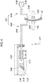
- FIG. 4 is a schematic configuration view of the measuring unit 200F.
- the measuring unit 200F has a tracing stylus 206F which is in contact with the lens front surface.
- the tracing stylus 206F is attached to the tip of an arm 204F.
- the arm 204F is held by an attaching support 201F so as to be movable in the X direction.
- the arm 204F is connected to a motor 216F via a rack 211F, a pinion 212F, a gear 214F, and the like.
- the arm 204F is moved in the X direction by the drive of the motor 216F, and the tracing stylus 206F is pressed against the front surface of the lens LE.
- the pinion 212F is attached to the rotation shaft of a detector 213F (for example, an encoder). The position of the tracing stylus 206F moved in the X direction is detected by the detector 213F.
- the measuring unit 200R includes a tracing stylus 206R which is in contact with the lens rear surface; a motor 216R that moves the tracing stylus 206R in the X direction; a detector 213R that detects the moving position of the tracing stylus 206R in the X direction.
- the tracing stylus 206F comes into contact with the lens front surface
- the tracing stylus 206R comes into contact with the lens rear surface.
- the lens LE is rotated by the lens holding unit 100
- the lens chuck shafts 102L and 102R are moved in the Y direction by the moving unit 300 based on the lens shape data, and accordingly, the lens profiles on the lens front surface and the lens rear surface, which correspond to a lens shape, are measured at the same time.
- the edge position of the lens front surface corresponding to the lens shape is measured by the measuring unit 200F
- the edge position of the lens rear surface corresponding to the lens shape is measured by the measuring unit 200R.
- FIG. 5 is a control system block diagram for the eyeglasses lens processing apparatus 1.
- the eyeglasses lens processing apparatus 1 includes the bevel formation data setting device 55.
- the bevel formation data setting device 55 includes the data acquisition unit 60.
- the data acquisition unit 60 acquires rim information necessary for forming a bevel for holding the eyeglasses lens on the rim of the eyeglasses frame.
- the data acquisition unit 60 may also function as a data input unit.
- the data acquisition unit 60 includes the display 62.
- the data acquisition unit 60 includes a data input unit 63.
- the display 62 may have a function of a touch panel and may be configured to include the data input unit 63.
- the bevel formation data setting device 55 includes the control unit 50.
- the control unit 50 also serves as a display control unit that controls the display of the display 62.
- the control unit 50 is connected to the data acquisition unit 60.
- the display control unit that controls the display of the display 62 may be provided in the data acquisition unit 60.
- the control unit 50 also serves as a control unit of the calculation means for obtaining the bevel shape data. Further, the control unit 50 also serves as the output means for outputting the data.
- the data acquisition unit 60 includes the memory 70 which is an example of storage means.
- Various data acquired by the data acquisition unit 10 are stored in the memory 70.
- preset bevel information is stored in the memory 70.
- various programs for controlling the operation of the bevel formation data setting device 55 are stored.
- the memory 70 may be separated from the data acquisition unit 60.
- control unit 50 also serves as a control unit for the eyeglasses lens processing apparatus 1 and is configured to control the entire eyeglasses lens processing apparatus 1.
- the control unit 50 is connected to the electrical system components (motors and the like) of each unit illustrated in FIGs. 1 to 4 .
- the control unit 50 is configured to perform various calculations for lens processing.
- Various programs related to peripheral processing of the lens LE are stored in the memory 70.
- the data acquisition unit 60 may be connected to a lens shape measuring device 30.
- the lens shape measuring device 30 measures the shape of the rim of the eyeglasses frame to obtain the lens shape (target shape for peripheral processing of the lens) of the lens LE attached to the rim as rim information. Further, after the lens shape measuring device 30 obtains the frame curve information based on the measurement result of the shape of the rim, the frame curve information may be acquired by the data acquisition unit 60.
- the bevel formation data setting device 55 may be separated from the eyeglasses lens processing apparatus 1.
- the bevel formation data setting device 55 and the control unit of the eyeglasses lens processing apparatus 1 are configured to enable data communication.
- the eyeglasses frame is a high-curve frame
- the lens LE is a high-curve lens
- the bevel that holds the lens LE on the rim of the eyeglasses frame is a high-curve bevel
- the front bevel LVf and the rear bevel LVr are individually processed by the front bevel processing tool 162 and the rear bevel LVr, respectively. Therefore, in the formation of the high-curve bevel, as illustrated in FIG.
- a height Vfh of the front bevel LVf and a height Vrh of the rear bevel LVr are processed in different amounts according to the groove shape of the rim.
- the bevel apex LVt may be plano-processed with a bevel apex width Vw corresponding to the groove shape of the rim.
- the bevel apex LVt is processed by the flat-finished surface 164a.
- the data acquisition unit 60 acquires the lens shape data (rn, ⁇ n) of the lens LE.
- rn is the vector length data
- ⁇ n is the vector angle data.
- n is 1000 points.
- the contour shape of the rim of the eyeglasses frame measured by the lens shape measuring device 30 is acquired by the data acquisition unit 60.
- the lens shape data may be acquired by the data acquisition unit 60 by calling the data stored in the memory 20.
- FIG. 7 is a screen example of the display 62 when processing conditions are set.
- a screen 601 of the display 62 displays a right eye lens shape TGR and a left eye lens shape TGL.
- Layout data for arranging the optical center position of the lens LE with respect to the target lens shape is input for the peripheral processing of the lens LE.
- the layout data includes a left-right lens shape center-to-center distance FPD (center-to-center distance between a geometric center TCR of the right eye lens shape TGR and a geometric center TCL of the left eye lens shape TGL), a pupillary distance PD (distance between a right eye optical center OCR and a left eye optical center OCL), and a height distance of the optical center with respect to the geometric center of the left and right lens shapes.
- FPD center-to-center distance between a geometric center TCR of the right eye lens shape TGR and a geometric center TCL of the left eye lens shape TGL
- a pupillary distance PD distance between a right eye optical center OCR and a left eye optical center OCL
- a height distance of the optical center with respect to the geometric center of the left and right lens shapes can be input using a numeric keypad displayed by touching the display field on the screen.
- the material (plastic, polycarbonate, and the like) of the lens can be set by a setting field 641a.
- a lens material selection screen is displayed as a pop-up screen, and the lens material can be selected from the pop-up screen.
- the type (material of the rim) of the eyeglasses frame can be set by a setting field 641b.
- the eyeglasses frame type selection screen is displayed as a pop-up screen.
- the type can be selected from metal (metal frame), cell (cell frame), two-point (rimless frame), and Nyroll (half rim).
- metal or cell which is distinguished by the material of the rim, is selected, it is necessary to form a bevel on the lens LE, and thus, the setting screen for setting and inputting the data necessary for forming the bevel is displayed.
- FIG. 8 is an example of a screen 610 displayed on the display 62, that is, a screen for setting the rim information when either the metal or cell of the rim material is selected.
- a rim material display field 651a whether the selected rim material is metal or cell is displayed. Further, the screen 610 may display a selection field 651b for selecting the direction of the rim groove as rim information.
- a direction along the frame curve (the curvature of the rim in the left-right direction), and a direction parallel to a predetermined plane (for example, a plane defined by four points of the left end, the right end, the upper end, and the lower end of the contour shape of the rim) can be selected regardless of the frame curve.
- a predetermined plane for example, a plane defined by four points of the left end, the right end, the upper end, and the lower end of the contour shape of the rim
- a figure 662a illustrating a case where the rim groove is arranged in a direction along the frame curve
- a figure 662b illustrating a case where the rim groove is arranged in a direction parallel to a predetermined plane.
- the direction of the rim groove may be selected.
- the angle of the direction of the rim groove may be directly input.
- a selection field 651c for selecting the type of the cross-sectional shape of the rim is displayed on the screen 610.
- a screen for selecting the type of the rim groove is displayed as a pop-up screen, and one of the plurality of type information can be selected.
- the type of the cross-sectional shape of the rim is the type of groove shape (hereinafter, rim groove) of the section of the rim.
- the shape of the rim groove is acquired by the control unit 50 of the data acquisition unit 60 by being selected by the operator from a plurality of typical predetermined shapes.
- one shape of the rim groove can be selected from three predetermined types: a rectangular shape (square shape), a triangular shape, and a round shape (the cross-sectional shape of the groove is a part of a circle).
- a rectangular groove figure 664a, a triangular groove figure 664b, and a round groove figure 664c which respectively imitate the rectangular shape (square shape), the triangular shape, and the round shape indicating the type of the rim groove. Accordingly, it is possible to help the operator understand which type of rim groove to select when the operator selects the type of rim groove.
- the operator confirms the rim groove of the eyeglasses frame and selects which type the rim groove is by using the selection field 651c.
- the type of the rim groove may be selected by a method in which one of the rectangular groove figure 664a, the triangular groove figure 664b, and the round groove figure 664c displayed in the display field 663 is designated.
- the setting screen 670 for setting parameters required for forming a bevel corresponding to the rim based on the selected type of the rim groove is displayed.
- the setting screen 670 is displayed within the screen 610, but a screen different from the screen 610 may be displayed as a pop-up screen, or may be displayed on the entire screen 610.
- the state (a) illustrated in FIG. 9 is an example in which a rectangular shape is selected as the type of the rim groove. Further, in the figure imitating the groove shape of the display field 663, the color of the figure of the selected type of the rim groove is highlighted, and the other figures are switched to the light color display. Accordingly, the operator can recognize which type of rim groove is selected.
- the parameters corresponding to the type of the rim groove include at least a groove width Gw and the groove depth Gd as the feature amount of the shape of the rim groove.
- the type of the rim groove is a rectangular shape
- the value of the groove width Gw is input into an input field 671a
- the groove depth Gd is input into an input field 671b.
- the value of a rear surface side rim width Rrt may be input into an input field 671c. It is not always necessary to input the rear surface side rim width Rrt, and a standard value stored in the memory 70 may be used.
- the operator can recognize that the groove width and the groove depth of the rim groove, which are parameters required for forming a bevel in a case of the rectangular shape. Further, when the input field 671c for the rim width Rrt is displayed, the operator understands the necessity of the value of the rim width Rrt.
- the operator measures the groove width and the groove depth of the rim groove of the eyeglasses frame (for example, a caliper or the like is used), and inputs the measured values into the input fields 671a and 671b.
- the input field 671c for the rear surface side rim width Rrt is displayed, the measured value of the rear surface side rim width is input into the input field 671c.
- a numeric keypad is displayed as a pop-up screen, and a numerical value can be input by the numeric keypad.
- State (b) illustrated in FIG. 9 is an example in which a triangular shape is selected as the type of the rim groove.
- the parameter needs to be the groove width, but the groove depth may not be required. This is because, for example, in a case of a triangular shape, the groove depth has a constant relationship (for example, a value of half the groove width or a value obtained by multiplying the groove width by a certain coefficient) with the groove width, and the groove depth is automatically determined when the groove width is determined. Therefore, in a case of a triangular shape, the input field 671a for the groove width Gw is displayed, but the input field 671b for the groove depth Gd is not displayed.
- the input of the value of the groove depth Gd is restricted. Therefore, when the rim groove has a triangular shape, the operator can recognize that the groove depth is not necessary as a parameter for forming the bevel.
- State (c) illustrated in FIG. 9 is an example in which a round shape is selected as the type of the rim groove.
- the parameter needs to be the groove width, but the groove depth may not be required. This is for the same reason as that in the case of a triangular shape. Therefore, in a case of a round shape, the input field 671a for the groove width Gw is displayed, but the input field 671b for the groove depth Gd is not displayed. Therefore, in a case of a round shape, the operator can recognize that the groove depth is not necessary as a parameter for forming the bevel.
- the parameters required for forming a bevel corresponding to the rim type are displayed to be identifiable corresponding to the rim type, and thus, even an operator who is unfamiliar with lens processing can easily set the values of the parameters required for forming a bevel corresponding to the rim type.
- the setting screen for parameters required for forming a bevel corresponding to the rim is displayed, the operation of the operator is guided, and thus, even the operator who is unfamiliar with processing can easily understand the setting work required for forming a bevel and can easily set the bevel.
- FIG. 10 illustrates another example of a method of displaying the parameters, which are required for forming the bevel corresponding to the rim, to be identifiable.
- State (a) illustrated in FIG. 10 illustrates a case where the rim groove has a triangular shape
- state (b) illustrated in FIG. 10 illustrates a case where the rim groove has a round shape.
- the input field 671b for the groove depth Gd is displayed in a color different from that of the input field 671a for the groove width Gw. In other words, such a difference in color makes it possible to identify the necessity of inputting the groove depth Gd.
- FIG. 10 illustrates another example of a method of displaying the parameters, which are required for forming the bevel corresponding to the rim, to be identifiable.
- State (a) illustrated in FIG. 10 illustrates a case where the rim groove has a triangular shape
- state (b) illustrated in FIG. 10 illustrates a case where the rim groove has a round shape.
- the input field 671b for the depth Gd is provided, and thus the value of the groove depth Gd can be input as needed.
- the operator can measure the groove depth and input the value into the input field 671a.
- the numeric keypad is displayed as a pop-up screen, and a numerical value can be input.
- the control unit 50 may obtain the groove depth Gd assuming that the relationship between the groove width Gw and the groove depth Gd is constant, and may display that the obtained value is automatically input into the input field 671b for the groove depth Gd. Such a display is also included in the method of displaying the parameters to be identifiable.
- the method of displaying the parameters, which are required for forming the bevel corresponding to the rim, to be identifiable is not limited to the above description, and various modifications are possible, such as a method of restricting the input in a tabular format (a format in which the numerical value input fields corresponding to the parameters are represented in a table).
- a triangular shape is automatically set in the selection field 651c for selecting the type of the cross-sectional shape of the rim.
- a screen including a figure imitating the rim groove having a triangular shape is displayed in the same manner as in the state (b) illustrated in FIG. 9 or the state (a) illustrated in FIG. 10 .
- the groove shape is standardly a triangular shape. Therefore, by selecting metal as the material of the rim, the rim type is indirectly selected, and the parameters corresponding to the rim are also indirectly set.
- the groove width is 1.0 mm and the groove depth is 0.4 mm.
- the opening angle (the angle formed by the front slope and the rear slope of the groove) of the groove is 110 degrees. Therefore, a standard value may be automatically entered and displayed as an initial value in the input field 671a for the groove width Gw shown in the state (b) illustrated in FIG. 9 or the state (a) illustrated in FIG. 10 . Further, in the input field 671b for the groove depth Gd shown in the state (a) illustrated in FIG. 10 , a standard groove depth value may be automatically entered and displayed. Accordingly, the operator understands that the rim measurement is not required. When the rim of the eyeglasses frame is standard, the operator completes the setting as it is. On the other hand, when the rim is different from the standard one, the operator may input a value obtained by measuring at least the groove width.
- an input field 651d for inputting a value of the frame curve (curvature in the left-right direction of the rim) is provided.
- the frame curve is used in the calculation of the bevel formation corresponding to the frame curve when the direction along the frame curve is selected as the direction of the rim groove.
- the frame curve may be acquired by receiving the measurement data of the lens shape measuring device 30 by the data acquisition unit 60. In this case, the value acquired by the data acquisition unit 60 is displayed in the input field 651d.
- the lens peripheral surface processing mode auto bevel processing, forced bevel processing, plano-processing, hole processing, and the like
- the presence/absence of polishing, the presence/absence of chamfering, and the lens chucking mode can be set (for example, selected from predetermined selection conditions) by the input fields 641c, 641d, 641e, and 641f.
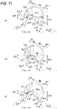
- FIG. 11 is a view describing a method of obtaining the bevel shape data.
- FIG. 11 is a case where the material of the rim is a cell and the direction of the rim groove is along the frame curve.
- State (a) illustrated in FIG. 11 illustrates a case where the rim groove has a rectangular shape
- state (b) illustrated in FIG. 11 illustrates a case where the rim groove has a triangular shape
- state (c) illustrated in FIG. 11 illustrates a case where the rim groove has a round shape, respectively.
- a tilt angle ⁇ g of the rim groove is an angle (the tilt angle of the rim with respect to the X direction which is the shaft direction of the lens chuck shaft 102 that holds the lens LE) obtained from the frame curve.
- the front skirt LCf is not formed in the formation of the bevel of the high-curve lens.
- the lens LE is stably held in the rim groove.
- the rear surface side rim width Rrt is taken into consideration, and the height Vrh of the rear bevel LVr is obtained such that the rear surface side rim does not abut thereon.
- the value of the rear surface side rim width Rrt may be determined based on a standard value.
- the height Vrh of the rear bevel LVr is obtained mathematically based on the groove width Gw, the groove depth Gd, the tilt angle ⁇ g of the rim groove, and the tilt angle ⁇ r of the processed slope 163Vr of the rear bevel processing tool 163. This calculation is performed by the control unit 50.
- the tilt angle ⁇ g differs depending on the vector angle ⁇ n of the lens shape. Therefore, the height Vrh may be calculated for each vector angle ⁇ n, but may be determined as the maximum value of each vector angle ⁇ n.
- the height Vfh of the front bevel LVf is obtained mathematically based on the groove width Gw, the groove depth Gd, the tilt angle ⁇ g of the rim groove, and the tilt angle ⁇ f of the processed slope 162Vf of the front bevel processing tool 162.
- the bevel apex width Vw is obtained mathematically from the relationship of the groove width Gw, the groove depth Gd, the tilt angle ⁇ g, and the rear tilt angle ⁇ r when the position of the rear bevel apex Vrt on the bottom surface Vg of the rim groove and the intersection Lvc on the front side surface Vsf of the rim groove are known.
- the opening angle formed by the front slope Vaf and the rear slope Var of the rim groove having a triangular shape is a standard angle (for example, 110 degrees). Since the groove depth of the triangular shape is obtained by determining the groove width Gw, the groove depth may not be set on the setting screen 670.
- the height Vfh of the front bevel LVf, the height Vrh of the rear bevel LVr, and the bevel apex width Vw are obtained mathematically based on the groove width Gw, the groove depth Gd, the tilt angle ⁇ g, the tilt angle ⁇ f, and the tilt angle ⁇ r.
- the calculation method of the bevel shape data (the height Vfh of the front bevel, the height Vrh of the rear bevel, and the bevel apex width Vw) is not limited to the above, and various methods can be used.
- the height Vfh of the front bevel LVf may be a constant value
- the height Vrh of the rear bevel LVr and the bevel apex width Vw may be obtained corresponding to the groove width Gw and the groove depth Gd.
- the groove width Gw and the height Vfh of the front bevel may be constant values.
- FIG. 12 is a view describing a method of obtaining the bevel shape data when the direction of the rim groove is parallel to a predetermined plane.
- the direction parallel to the predetermined plane is a direction parallel to the plane perpendicular to the lens chuck shaft 102 when the lens LE is held by the lens chuck shaft 102 during processing of the lens LE.
- State (a) illustrated in FIG. 12 is a case where the rim groove has a rectangular shape.
- the front bevel apex Vft and the rear bevel apex Vrt abut on the bottom surface Vg of the rim groove.
- the front side end Rfc of the rim groove abuts on the slope of the front bevel LVf and the rear side end Rrc of the rim groove abuts on the slope of the rear bevel LVr.
- each of the intersection Lvc and the rear skirt LCr is separated from the rim side by a certain distance.
- the height Vfh of the front bevel, the height Vrh of the rear bevel, and the bevel apex width Vw are obtained mathematically based on the groove width Gw, the groove depth Gd, the tilt angle ⁇ f, and the tilt angle ⁇ r.
- State (b) illustrated in FIG. 12 is a case where the rim groove has a triangular shape.
- the front bevel apex Vft and the rear bevel apex Vrt abut on the front slope Vaf and the rear slope Var of the rim groove, respectively.
- each of the intersection Lvc and the rear skirt LCr is separated from the rim side by a certain distance.
- the height Vfh of the front bevel, the height Vrh of the rear bevel, and the bevel apex width Vw are obtained mathematically based on the tilt angle ⁇ f and the tilt angle ⁇ r.
- the bevel apex width Vw may not be formed or may be as wide as chamfering.
- State (c) illustrated in FIG. 12 illustrates a case where the rim groove has a round shape.
- the front bevel apex Vft and the rear bevel apex Vrt abut on the arc Gcs of the rim groove.
- the front side end Rfc of the rim groove abuts on the slope of the front bevel LVf and the rear side end Rrc of the rim groove abuts on the slope of the rear bevel LVr.
- each of the intersection Lvc and the rear skirt LCr is separated from the rim side by a certain distance.
- the height Vfh of the front bevel, the height Vrh of the rear bevel, and the bevel apex width Vw are obtained mathematically based on the groove width Gw, the tilt angle ⁇ f, and the tilt angle ⁇ r.
- the calculation method of the bevel shape data (the height Vfh of the front bevel, the height Vrh of the rear bevel, and the bevel apex width Vw) is not limited to the above, and various methods can be used.
- the bevel apex width Vw may be a constant width for chamfering.
- the height Vfh of the front bevel may be a constant distance in any groove shape.
- the bevel shape data and the setting data of the processing conditions which are obtained by the bevel formation data setting device 55, are output to the control unit 50 of the eyeglasses lens processing apparatus 1 (in the example, the control unit 50 also serves as a control unit of the bevel formation data setting device 55 and the eyeglasses lens processing apparatus 1).
- the processing operation of the lens LE by the eyeglasses lens processing apparatus 1 will be briefly described.
- the operator holds the lens LE on the lens chuck shaft 102 and starts processing.
- the lens profile is measured prior to the peripheral processing of the lens LE.
- the control unit 50 controls the drive of the lens profile measuring unit 200 and the moving unit 300 based on the acquired lens shape data, and measures the shapes of the front surface and the rear surface of the lens LE held by the lens chuck shaft 102. By this measurement, the front surface profile and the rear surface profile of the lens LE corresponding to the lens shape can be obtained.
- the control unit 50 obtains the path of the bevel formed at the peripheral edge of the lens LE by the predetermined calculation based on the acquisition results of the front surface profile and the rear surface profile of the lens LE. For example, when the auto bevel of the high-curve lens is set, the control unit 50 makes the bevel curve of the bevel path (for example, the path between the front bevel apex and the rear bevel apex) the same as the front surface curve of the lens LE. Otherwise, the bevel curve may be approximated to the frame curve.
- the bevel curve of the bevel path for example, the path between the front bevel apex and the rear bevel apex
- control unit 50 obtains (acquires) the processing control data for forming a bevel on the lens LE based on the bevel formation data set by the bevel formation data setting device 55 (more specifically, based on the bevel shape data calculated based on the bevel formation data).
- the control unit 50 acquires the processing control data for forming the front bevel LVf of the lens LE by the front bevel processing tool 162, the processing control data for forming the rear bevel LVr of the lens LE by the rear bevel processing tool 163, and the processing control data for processing the bevel apex width by the flat-finished surface 164a of the finishing tool 164 based on the height Vfh of the front bevel, the height Vrh of the rear bevel, and the bevel apex width Vw, which are acquired by the bevel formation data setting device 55.
- the processing operation of forming a bevel at the peripheral edge of the lens LE is executed.
- the control unit 50 controls the moving unit 300 based on the lens shape while rotating the lens LE, and the peripheral edge of the lens LE is roughed by the roughing tool 166. Subsequently, the control unit 50 controls the moving unit 300 based on the acquired processing control data of the bevel to form a bevel at the peripheral edge of the lens LE.
- control unit 50 controls the drive of the moving unit 300 to form the front bevel LVf of the lens LE by the front bevel processing tool 162, to form the rear bevel LVr of the lens LE by the rear bevel processing tool 163, and to process the peripheral edge of the lens LE so as to secure the bevel apex width by the flat-finished surface 164a of the finishing tool 164.
- FIG. 13 is an example of the bevel simulation screen in the forced bevel processing mode.
- the following bevel simulation screen 680 can be used to perform the setting for specialized bevel formation. This function may be provided in the bevel formation data setting device 55.
- a bevel cross-sectional shape figure 682 at the vector angle designated by the cursor 681 is displayed on the upper left on the screen. Accordingly, the operator can confirm the bevel shape at any vector angle.
- Each value of the bevel formation data can be changed by a display field 683.
- each value of the front bevel height, the rear bevel height, the bevel apex width, the bevel position, and the tilt amount is displayed.
- Each value can be changed to a desired value by operating the numeric keypad displayed as a pop-up screen by the operator touching the fields of each value. Accordingly, it is possible to appropriately change the bevel information set in advance by the bevel formation data setting device 55.
- control unit 50 obtains the processing control data after calculating the path of the bevel formed at the peripheral edge of the lens LE in the same manner as described above, and controls the moving unit 300 based on the processing control data to form the bevel at the peripheral edge of the lens LE by each processing tool.
- the groove width and the groove depth of the rim groove are the same regardless of the vector angle (the same vector angle as that of the lens shape) of the rim, but may differ according to the location of the vector angle depending on the rim.
- the groove width and the groove depth of the rim groove may be set at a plurality of locations of the vector angles of the rim.
- FIG. 14 is an example of a case where the groove width and the groove depth of the rim groove are set at a plurality of locations.
- the setting screen 690 of FIG. 14 may be displayed as a pop-up screen or may be switched to another screen by touching a button (not illustrated) displayed on the screen 610, for example.
- the groove width and the groove depth of the rim groove designate four points of an upper end point FPa, a lower end point FPb, a left end point FPc, and a right end point FPd with respect to center points FTC on the left, right, top, and bottom of the rim (the left, right, top, and bottom in FIG. 14 are the left, right, top, and bottom when the eyeglasses frame is worn).
- the groove width and groove depth at the points FPa, FPb, FPc, and FPd can be set respectively by the input fields 691a, 691b, 691c, and 691d provided so as to correspond to each point. Then, the groove width and the groove depth between the points FPa, FPb, FPc, and FPd may be obtained for each vector angle so as to interpolate the groove width and the groove depth set at each point, for example.
- the setting of the groove depth which is an example of the parameters required for forming a bevel corresponding to the rim type (cross-sectional shape of the rim groove), is limited, or the necessity of setting is displayed to be identifiable, such as being displayed in a different color.
Landscapes
- Engineering & Computer Science (AREA)
- Chemical & Material Sciences (AREA)
- Ceramic Engineering (AREA)
- Inorganic Chemistry (AREA)
- Mechanical Engineering (AREA)
- Eyeglasses (AREA)
- Grinding And Polishing Of Tertiary Curved Surfaces And Surfaces With Complex Shapes (AREA)
Abstract
Description
- The present disclosure relates to a bevel formation data setting device for setting a bevel for holding an eyeglasses lens on a rim of an eyeglasses frame, an eyeglasses lens processing apparatus that forms a bevel at a peripheral edge of the eyeglasses lens, and a bevel formation data setting program.
- An eyeglasses lens processing apparatus is known in which a front bevel (the slope on the front side of the bevel) and a rear bevel (the slope on the rear side of the bevel) of the bevel, which hold the eyeglasses lens on the rim of a high-curve frame, are formed at the peripheral edge of the eyeglasses lens by different processing tools (for example, refer to
JP-A-H11-048113 JP-A-2016-049592 - Incidentally, in the device of the related art, the setting of a bevel formation state, such as the height of the front bevel and the height of the rear bevel is performed by a setting method in which each operator recognizes the necessary parameters, and inputs numerical values such as the height of the front bevel, the height of the rear bevel, and the like. For the setting, the operator needs to have specialized knowledge and high skill, and it is not easy for the operator who is unfamiliar with lens processing to set the bevel formation data.
- The technical object of the present disclosure is to provide a bevel formation data setting device, an eyeglasses lens processing apparatus, and a bevel formation data setting program, which make it easier for even an operator who is unfamiliar with lens processing to set bevel formation data.
- (1) A bevel formation data setting device for setting a bevel for holding an eyeglasses lens on a rim of an eyeglasses frame, including:
- a rim information acquisition means for acquiring rim information of the eyeglasses frame; and
- a display control means for controlling display of a display,
- in which the display control means causes the display to display a setting screen for setting bevel formation data based on the acquired rim information, the setting screen corresponding to the rim.
- (2) In the bevel formation data setting device according to the above-described (1), the display control means may cause the display to display information to be identifiable on the setting screen based on the acquired rim information, the information being required for forming the bevel corresponding to the rim.
- (3) In the bevel formation data setting device according to the above-described (2), the rim information may include type information indicating a type of a cross-sectional shape of the rim.
- (4) In the bevel formation data setting device according to the above-described (3), the type information may include at least a type of a groove shape of the rim, and the information may include parameters related to at least a groove width and a groove depth of the groove shape of the rim.
- (5) In the bevel formation data setting device according to the above-described (3) or (4), the rim information acquisition means may acquire the type information with a selection of one from a plurality of types of cross-sectional shapes of the rim, which are displayed on the setting screen by control of the display control means.
- (6) An eyeglasses lens processing apparatus including:
- a processing tool that forms a bevel for holding an eyeglasses lens on a rim of an eyeglasses frame at a peripheral edge of the eyeglasses lens; and
- the bevel formation data setting device according to any one of the above-described (1) to (5),
- in which the eyeglasses lens processing apparatus forms the bevel at the peripheral edge of the eyeglasses lens, based on bevel formation data set by the bevel formation data setting device, with using the processing tool.
- (7) A bevel formation data setting program executed by a control unit of a bevel formation data setting device for setting a bevel for holding an eyeglasses lens on a rim of an eyeglasses frame, the bevel formation data setting program including instructions which cause the control unit of the bevel formation data setting device to perform:
- a rim information acquisition step of acquiring rim information of the eyeglasses frame; and
- a display control step of controlling display of a display,
- in which the display control step includes a step of causing the display to display a setting screen for setting bevel formation data based on the acquired rim information, the setting screen corresponding to the rim.
- (8) In the bevel formation data setting program according to the above-described (7), the display control step may include a step of causing the display to display information to be identifiable on the setting screen based on the acquired rim information, the information being required for forming the bevel corresponding to the rim.
- According to the present disclosure, even an operator who is unfamiliar with lens processing can more easily set bevel formation data.
-
-
FIG. 1 is a view describing a configuration of a processing mechanism unit included in an eyeglasses lens processing apparatus. -
FIG. 2 is an example of a processing tool attached to a processing tool rotation shaft. -
FIG. 3 is a schematic configuration view of a second processing tool unit. -
FIG. 4 is a schematic configuration view of a lens profile measuring unit. -
FIG. 5 is a control system block diagram for a bevel formation data setting device and the eyeglasses lens processing apparatus. -
FIG. 6 is a view illustrating the height of a front bevel, the height of a rear bevel, and a bevel apex width in a bevel formed on a lens LE. -
FIG. 7 is a screen example of a display when processing conditions are set. -
FIG. 8 is a view illustrating a screen example for setting rim information. -
FIG. 9 is a view illustrating an example of a setting screen for setting parameters required for forming a bevel corresponding to a rim. -
FIG. 10 is a view illustrating another example of a method of displaying the parameters, which are required for forming the bevel corresponding to the rim, to be identifiable. -
FIG. 11 is a view describing a method of obtaining bevel shape data when a direction of a rim groove is a direction along a frame curve. -
FIG. 12 is a view describing a method of obtaining the bevel shape data when the direction of the rim groove is parallel to a predetermined plane. -
FIG. 13 is a view illustrating an example of a bevel simulation screen in a forced bevel processing mode. -
FIG. 14 is a view illustrating an example of a case where a groove width and a groove depth of the rim groove are set at a plurality of locations. - Hereinafter, the present embodiment will be described below with reference to the drawings.
FIGs. 1 to 14 are views describing a bevel formation data setting device, an eyeglasses lens processing apparatus, and a bevel formation data setting program according to the present embodiment. - For example, a bevel formation data setting device (for example, a bevel formation data setting device 55) is used to set a bevel for holding an eyeglasses lens on a rim of an eyeglasses frame. For example, the bevel formation data setting device includes a rim information acquisition means (for example, a data acquisition unit 60). For example, the rim information acquisition means acquires rim information of the eyeglasses frame. For example, the rim information acquisition means may acquire the rim information by inputting the rim information on an input screen, or may acquire the rim information by receiving the transmitted rim information. Further, for example, the bevel formation data setting device includes a display control means (for example, a control unit 50). For example, the display control means controls the display of the display (for example, a display 62).
- For example, the rim information includes at least type information indicating the type of cross-sectional shape of the rim. For example, the type of the cross-sectional shape of the rim is the type of groove shape of the section of the rim. For example, the type of the groove shape may include any of a rectangular shape (square shape), a triangular shape, and a round shape (the cross-sectional shape of the groove is a part of a circle). The rectangular shape of the rim groove may include a U-shape in which the inner corner of the groove is rounded. Further, the triangular shape of the rim groove may include a case where the inner side of the groove is rounded. Further, the round shape of the rim groove may include a case where the cross-sectional shape of the groove is a part of the elliptical shape.
- For example, the display control means causes the display to display a setting screen (for example, a
setting screen 670, and a setting screen 690) for setting bevel formation data. For example, the display control means causes the display to display the setting screen corresponding to the rim based on the acquired rim information. Accordingly, even an operator who is unfamiliar with lens processing (for example, an operator who lacks specialized knowledge of bevel setting) can more easily appropriately set the bevel by following the setting screen. - For example, the display control means may display the parameters, which are required for forming a bevel corresponding to the rim, to be identifiable on the setting screen based on the acquired rim information. For example, the display control means may be displayed on the setting screen in a form in which the operator recognizes the necessity of setting the parameter corresponding to the rim type. For example, the parameter may indicate a feature amount of the groove shape of the rim type. For example, the parameters may include at least the groove width and the groove depth of the groove shape of the rim. For example, when the groove shape of the rim is a rectangular shape, the parameters need to be the groove width and the groove depth. Meanwhile, when the groove shape of the rim is a triangular or round shape, the parameter needs to be the groove width, but the groove depth may not be required. This is because, for example, when the groove shape of the rim is a triangular or round shape, the groove depth has a constant relationship (for example, a value of half the groove width or a value obtained by multiplying the groove width by a certain coefficient) with the groove width, and the groove depth is automatically determined when the groove width is determined. Therefore, for example, the display control means displays the input field for both values of the groove width and the groove depth on the setting screen when the groove shape of the rim is a rectangular shape, and displays the input field for the value of the groove width on the setting screen or does not display the input field for the groove depth on setting screen (for example, input is restricted) when the groove shape of the rim is a triangular or round shape. Accordingly, the display control means makes it identifiable that it is not necessary to input the groove width. Otherwise, for example, when the groove shape of the rim is a triangular or round shape, the display control means may display the color of the input field for the groove depth in a color different from that of the input field for the groove width, and may make it identifiable that it is not necessary to input the groove width. Accordingly, even an operator who is unfamiliar with lens processing can easily set the values of the parameters required for forming a bevel.
- The identifiable parameters may be set directly or indirectly. For example, when the material of the rim is a cell, there are three types of cross-sectional shapes of the rim: a rectangular shape, a triangular shape, and a round shape. On the other hand, when the material of the rim is metal, the type of the cross-sectional shape of the rim is standardly a triangular shape. Therefore, when the material of the rim is acquired as metal by the rim information acquisition means, the type of the cross-sectional shape of the rim is indirectly set to a triangular shape, and thus the parameter corresponding to the rim is also indirectly set. Therefore, the display control means may display the parameters, which are required for forming a bevel, to be identifiable on the setting screen based on the acquired rim material.
- For example, the display control means may display type selection information for selecting the type of the cross-sectional shape of the rim on the setting screen. For example, the rim information acquisition means may acquire the type of the cross-sectional shape of the rim by selecting one from the rim type selection information. Accordingly, even those who are unfamiliar with lens processing can more easily appropriately set the bevel by selecting the groove type of the rim.
- The display control means may display selection information for selecting the direction of the groove of the rim on the setting screen. For example, the selection information of the direction of the groove of the rim includes a direction along the frame curve, and a direction in a certain direction regardless of the frame curve, that is, a direction parallel to a predetermined plane (for example, a plane defined by four points of the left end, the right end, the upper end, and the lower end of the contour shape of the rim). In this case, by selecting one from the selection information of the direction of the groove of the rim, the rim information acquisition means acquires the rim information useful for forming a bevel.
- Further, the rim information acquisition means may acquire the frame curve value as a part of the rim information. The frame curve value is used for the calculation of the bevel shape data when the direction of the groove of the rim is a direction along the frame curve. For example, the display control means may display an input screen for inputting the frame curve value on the display, input the frame curve value by the input screen, and accordingly, the rim information acquisition means may acquire the frame curve value. Further, regarding the frame curve value, the rim information acquisition means may acquire the frame curve value by receiving the data transmitted from the device for measuring the shape of the rim.
- For example, the bevel formation data setting device includes a calculation means (for example, the control unit 50) for obtaining bevel shape data, and an output means (for example, the control unit 50) for outputting the calculation result. For example, the calculation means obtains the bevel shape data for forming a bevel in the eyeglasses lens based on the type of the cross-sectional shape of the rim acquired by the rim information acquisition means and the parameters (for example, the groove width and the groove depth of the groove shape of the rim) set on the setting screen. For example, the bevel shape data includes at least the height of the front bevel on the front surface side of the eyeglasses lens and the height of the rear bevel on the rear surface side of the eyeglasses lens. The bevel shape data may include the bevel apex width. For example, the calculation means obtains the height of the front bevel based on the tilt angle of the processed slope of the front bevel processing tool (for example, a front bevel processing tool 162) for forming the front bevel. For example, the calculation means further obtains the height of the rear bevel based on the tilt angle of the processed slope of the rear bevel processing tool (for example, a rear bevel processing tool 163) for forming the rear bevel. Further, the calculation means obtains the tilt angle of the rim based on the frame curve information, and obtains the height of the front bevel and the height of the rear bevel based on the obtained tilt angle of the rim.
- For example, in the eyeglasses lens processing apparatus (for example, an eyeglasses lens processing apparatus 1) including: a processing tool (for example, the front
bevel processing tool 162 and the rear bevel processing tool 163) for forming a bevel for holding an eyeglasses lens on a rim of an eyeglasses frame at a peripheral edge of the eyeglasses lens, the bevel may be formed at the peripheral edge of the eyeglasses lens by the processing tool based on the set bevel formation data, and the bevel formation data setting device may be provided. For example, the eyeglasses lens processing apparatus includes a lens holding shaft (for example, a lens chuck shaft 102) for holding the eyeglasses lens. The eyeglasses lens processing apparatus includes a bevel processing tool having the front bevel processing tool (for example, the front bevel processing tool 162) that forms the front bevel on the front surface side of the eyeglasses lens; and the rear bevel processing tool (for example, the rear bevel processing tool 163) that forms the rear bevel on the rear surface side of the eyeglasses lens. For example, the eyeglasses lens processing apparatus includes a moving means (for example, a moving unit 300) that changes the relative positional relationship between the bevel processing tool and the eyeglasses lens held by the lens holding shaft. For example, the eyeglasses lens processing apparatus includes a processing control data acquisition means (for example, the control unit 50) that acquires processing control data for forming a bevel at the peripheral edge of the lens held by the lens holding shaft based on the bevel shape data obtained by the bevel formation data setting device. For example, the eyeglasses lens processing apparatus includes a control means (for example, the control unit 50) that controls the moving means based on the processing control data and forms a bevel at the peripheral edge of the eyeglasses lens by the bevel processing tool. - In addition, the present disclosure is not limited to the apparatus described in the present embodiment. For example, a control program (software) for performing the functions of the above-described embodiment is supplied to a system or an apparatus via a network or various storage media. In addition, a control unit (for example, a CPU or the like) of the system or the apparatus can read and execute the program.
- For example, the bevel formation data setting program includes a rim information acquisition step of acquiring rim information of the eyeglasses frame. For example, the bevel formation data setting program includes a display control step of controlling the display of the display. For example, in the display control step, a setting screen for setting the bevel formation data, that is, a setting screen corresponding to the rim, is displayed on the display based on the acquired rim information.
- One typical example of the present disclosure will be described with reference to the drawings.
FIG. 1 is a view describing a configuration of a processing mechanism unit included in the eyeglasseslens processing apparatus 1 according to the example. - For example, the eyeglasses
lens processing apparatus 1 includes alens holding unit 100 which is an example of a lens holding means. For example, the eyeglasseslens processing apparatus 1 includes a lensprofile measuring unit 200. For example, the eyeglasseslens processing apparatus 1 includes a firstprocessing tool unit 150. The firstprocessing tool unit 150 is configured to rotate a processing tool that processes the peripheral edge of a lens LE. For example, the eyeglasseslens processing apparatus 1 includes a secondprocessing tool unit 500. The secondprocessing tool unit 500 is configured to rotate a processing tool for performing at least one processing of chamfering and grooving on the peripheral edge of the lens LE after finishing. For example, the eyeglasseslens processing apparatus 1 includes the movingunit 300 which is an example of the moving means. The movingunit 300 is configured to change (adjust) the relative positional relationship between the lens LE and the processing tool of the firstprocessing tool unit 150. In addition, the movingunit 300 is configured to change (adjust) the relative positional relationship between the lens LE and the processing tool of the secondprocessing tool unit 500. - The
lens holding unit 100 includes alens chuck shaft 102 for narrowly holding (holding) and rotating the lens LE; and acarriage 101. Thelens chuck shaft 102 includes a pair oflens chuck shafts lens chuck shaft 102L is rotatably held by aleft arm 101L of thecarriage 101, and thelens chuck shaft 102R is rotatably held by theright arm 101R of thecarriage 101. The lens chuck shaft 102 (lens LE) is rotated by themotor 120. - The first
processing tool unit 150 includes amotor 160 for rotating a processingtool rotation shaft 161. The processingtool rotation shaft 161 is rotatably held by amain body base 170 in a positional relationship parallel to thelens chuck shaft 102. A plurality ofprocessing tools 168 for processing the peripheral edge of the lens LE are attached to the processingtool rotation shaft 161. -
FIG. 2 is an example of theprocessing tool 168 attached to the processingtool rotation shaft 161. Theprocessing tool 168 includes, for example, at least one of the frontbevel processing tool 162, the rearbevel processing tool 163, anormal finishing tool 164, apolishing tool 165, and aroughing tool 166. In the example, the grindstone is used as theprocessing tools 162 to 166, but a cutter may be used. - The
roughing tool 166 is used for roughing the peripheral edge of the lens LE. Thenormal finishing tool 164 has a V-groove 164V and a flat-finished surface 164a for forming a normal small bevel on the low-curve lens LE. The front bevel and the rear bevel are simultaneously formed at the peripheral edge of the low-curve lens by the V-groove 164V The heights of the front bevel and the rear bevel (distance in the radial direction of the lens LE with respect to the chuck center) formed by the V-groove 164V is, for example, 1 mm. Thepolishing tool 165 is used for further polishing the lens peripheral edge finished by thenormal finishing tool 164. - The rear
bevel processing tool 163 has a processed slope 163Vr for forming a rear bevel LVr (a bevel slope on the rear side of the lens LE) at the peripheral edge of the high-curve lens LE, and a processed surface 163Cr for forming a rear skirt LCr extending from the rear bevel LVr to the rear side of the lens at the peripheral edge of the lens LE. The frontbevel processing tool 162 has a processed slope 162Vf for forming a front bevel LVf (a bevel slope on the front side of the lens LE) at the peripheral edge of the high-curve lens LE. Further, the frontbevel processing tool 162 may have a processed surface 162Cf for forming a front skirt LCf extending from the front bevel LVf to the front side of the lens at the peripheral edge of the lens LE. In the bevel processing of the high-curve lens, there is also a method in which the front skirt LCf is not formed on the front side of the lens, and thus the processed surface 162Cf of the frontbevel processing tool 162 may not be provided. - The processed slope 162Vf of the front
bevel processing tool 162 has a size for forming the front bevel LVf having a height larger (the distance in the radial direction of the lens LE is long) than that of the front bevel formed by the V-groove 164V of thenormal finishing tool 164, on the high-curve lens. The processed slope 163Vr of the rearbevel processing tool 163 also has a size for forming the rear bevel LVr having a height larger (the distance in the radial direction of the lens LE is long) than that of the rear bevel formed by the V-groove 164V of thenormal finishing tool 164, on the high-curve lens. The processed slope 162Vf and the processed slope 163Vr have a size capable of forming a bevel height of, for example, 5 mm or more. A tilt angle αf (angle with respect to the X axis) of the processed slope 162Vf of the frontbevel processing tool 162 and a tilt angle αr of the processed slope 163Vr of the rearbevel processing tool 163 are stored in amemory 70 described later. - The front
bevel processing tool 162 may be arranged on the processingtool rotation shaft 161 apart from the rearbevel processing tool 163. Further, the frontbevel processing tool 162 may be arranged on a processing tool rotation shaft (for example, a processingtool rotation shaft 501 of the second processing tool unit 500) provided separately from the processingtool rotation shaft 161. Further, the frontbevel processing tool 162 may also use afront chamfering tool 502a (refer toFIG. 3 ) included in the secondprocessing tool unit 500. - In
FIG. 1 , the secondprocessing tool unit 500 is arranged in front of thecarriage 101.FIG. 3 is a schematic configuration view of the secondprocessing tool unit 500. Achamfering tool 502 for chamfering the peripheral edge (corner portion) of the lens LE is attached to the processingtool rotation shaft 501. Thechamfering tool 502 includes thefront chamfering tool 502a for chamfering the front surface edge of the lens LE, and achamfering tool 502b for chamfering the rear surface edge of the lens LE. For example, thechamfering tool 502 is composed of a grindstone, but may be a cutter. The processingtool rotation shaft 501 is rotatably held by anarm 510. Amotor 514, which is a drive source for rotating the processingtool rotation shaft 501, is attached to asupport member 512 that supports thearm 510. The rotation of themotor 514 is transmitted to the processingtool rotation shaft 501 via a rotation transmission mechanism (not illustrated) such as a gear or a belt arranged in thearm 510 or the like, and the processingtool rotation shaft 501 is rotated. Further, thearm 510 is attached to thesupport member 512 so as to be movable between the retracted position and the processing position. Amotor 516 for moving thearm 510 is attached to thesupport member 512. By moving thearm 510 by driving themotor 516, the processing tool rotation shaft 501 (chamfering tool 502) is moved from the retracted position to a predetermined processing position. Thesupport member 512 is attached to thebase 170 via anattachment member 518. - The moving
unit 300 is configured to adjust the relative positions of the lens LE held by thelens chuck shaft 102 and the processing tool (theprocessing tool 168 and the chamfering tool 502). For example, the movingunit 300 has a first movingunit 310 that changes the inter-shaft distance between thelens chuck shaft 102 and the processingtool rotation shaft 161 and therotation shaft 501, and a second movingunit 330 that moves the lens LE in the shaft direction of thelens chuck shaft 102. In the example, the shaft direction of thelens chuck shaft 102 is defined as the X direction. The direction in which the inter-shaft distance between thelens chuck shaft 102 and the processingtool rotation shaft 161 and therotation shaft 501 is changed is defined as the Y direction. - The first moving
unit 310 includes amotor 315. The rotation of themotor 315 causes a movingsupport 301 to move in the X direction. Accordingly, thecarriage 101 and the lens chuck shaft 102 (lens LE) mounted on the movingsupport 301 are moved in the X direction. The first movingunit 310 may be configured to move the processingtool rotation shaft 161 and therotation shaft 501 in the X direction. - The second moving
unit 330 includes amotor 335 for moving the carriage 101 (lens chuck shaft 102) in the Y direction. Thecarriage 101 is held by the movingsupport 301 to be movable in the Y direction alongshafts motor 335 is transmitted to aball screw 337 extending in the Y direction, and the carriage 101 (thelens chuck shaft 102 and the lens LE) is moved in the Y direction by the rotation of theball screw 337. In the example, the second movingunit 330 is configured to move thelens chuck shaft 102 in the Y direction, but the processingtool rotation shaft 161 and therotation shaft 501 may be configured to move in the Y direction. In other words, the second movingunit 330 may be configured to relatively change the inter-shaft distance between thelens chuck shaft 102 and the processingtool rotation shaft 161 and therotation shaft 501. - In
FIG. 1 , the lensprofile measuring unit 200 is arranged above thecarriage 101. The lensprofile measuring unit 200 is used to measure the profile of the lens front surface (front refractive surface) and the profile of the lens rear surface (rear refractive surface) of the lens LE. The lensprofile measuring unit 200 includes, for example, a measuringunit 200F for measuring the lens front surface profile and ameasuring unit 200R for measuring the lens rear profile shape. -
FIG. 4 is a schematic configuration view of the measuringunit 200F. The measuringunit 200F has atracing stylus 206F which is in contact with the lens front surface. Thetracing stylus 206F is attached to the tip of anarm 204F. Thearm 204F is held by an attachingsupport 201F so as to be movable in the X direction. Thearm 204F is connected to amotor 216F via arack 211F, apinion 212F, agear 214F, and the like. Thearm 204F is moved in the X direction by the drive of themotor 216F, and thetracing stylus 206F is pressed against the front surface of the lens LE. Thepinion 212F is attached to the rotation shaft of adetector 213F (for example, an encoder). The position of thetracing stylus 206F moved in the X direction is detected by thedetector 213F. - Since the configuration of the measuring
unit 200R for measuring the lens rear surface profile is symmetrical in the left-right direction with the measuringunit 200F, the description thereof will be omitted. The measuringunit 200R includes atracing stylus 206R which is in contact with the lens rear surface; amotor 216R that moves thetracing stylus 206R in the X direction; adetector 213R that detects the moving position of thetracing stylus 206R in the X direction. - When measuring the lens profile, the
tracing stylus 206F comes into contact with the lens front surface, and thetracing stylus 206R comes into contact with the lens rear surface. In this state, the lens LE is rotated by thelens holding unit 100, thelens chuck shafts unit 300 based on the lens shape data, and accordingly, the lens profiles on the lens front surface and the lens rear surface, which correspond to a lens shape, are measured at the same time. In other words, the edge position of the lens front surface corresponding to the lens shape is measured by the measuringunit 200F, and the edge position of the lens rear surface corresponding to the lens shape is measured by the measuringunit 200R. -
FIG. 5 is a control system block diagram for the eyeglasseslens processing apparatus 1. The eyeglasseslens processing apparatus 1 includes the bevel formationdata setting device 55. The bevel formationdata setting device 55 includes thedata acquisition unit 60. For example, thedata acquisition unit 60 acquires rim information necessary for forming a bevel for holding the eyeglasses lens on the rim of the eyeglasses frame. Thedata acquisition unit 60 may also function as a data input unit. For example, thedata acquisition unit 60 includes thedisplay 62. For example, thedata acquisition unit 60 includes adata input unit 63. For example, thedisplay 62 may have a function of a touch panel and may be configured to include thedata input unit 63. The bevel formationdata setting device 55 includes thecontrol unit 50. Thecontrol unit 50 also serves as a display control unit that controls the display of thedisplay 62. Thecontrol unit 50 is connected to thedata acquisition unit 60. The display control unit that controls the display of thedisplay 62 may be provided in thedata acquisition unit 60. Further, thecontrol unit 50 also serves as a control unit of the calculation means for obtaining the bevel shape data. Further, thecontrol unit 50 also serves as the output means for outputting the data. - For example, the
data acquisition unit 60 includes thememory 70 which is an example of storage means. Various data acquired by the data acquisition unit 10 are stored in thememory 70. In addition, preset bevel information is stored in thememory 70. In addition, various programs for controlling the operation of the bevel formationdata setting device 55 are stored. Thememory 70 may be separated from thedata acquisition unit 60. - Further, in the present example, the
control unit 50 also serves as a control unit for the eyeglasseslens processing apparatus 1 and is configured to control the entire eyeglasseslens processing apparatus 1. Thecontrol unit 50 is connected to the electrical system components (motors and the like) of each unit illustrated inFIGs. 1 to 4 . Thecontrol unit 50 is configured to perform various calculations for lens processing. Various programs related to peripheral processing of the lens LE are stored in thememory 70. - Further, the
data acquisition unit 60 may be connected to a lensshape measuring device 30. For example, the lensshape measuring device 30 measures the shape of the rim of the eyeglasses frame to obtain the lens shape (target shape for peripheral processing of the lens) of the lens LE attached to the rim as rim information. Further, after the lensshape measuring device 30 obtains the frame curve information based on the measurement result of the shape of the rim, the frame curve information may be acquired by thedata acquisition unit 60. - The bevel formation
data setting device 55 may be separated from the eyeglasseslens processing apparatus 1. In this case, for example, the bevel formationdata setting device 55 and the control unit of the eyeglasseslens processing apparatus 1 are configured to enable data communication. - The operation of the bevel formation
data setting device 55 and the eyeglasseslens processing apparatus 1 having the above configuration will be described. In the following, a case where the eyeglasses frame is a high-curve frame, the lens LE is a high-curve lens, and the bevel that holds the lens LE on the rim of the eyeglasses frame is a high-curve bevel will be mainly described. In the formation of the high-curve bevel, the front bevel LVf and the rear bevel LVr are individually processed by the frontbevel processing tool 162 and the rear bevel LVr, respectively. Therefore, in the formation of the high-curve bevel, as illustrated inFIG. 6 , a height Vfh of the front bevel LVf and a height Vrh of the rear bevel LVr are processed in different amounts according to the groove shape of the rim. Further, the bevel apex LVt may be plano-processed with a bevel apex width Vw corresponding to the groove shape of the rim. For example, the bevel apex LVt is processed by the flat-finished surface 164a. - When processing the peripheral edge of the lens LE, the
data acquisition unit 60 acquires the lens shape data (rn, θn) of the lens LE. rn is the vector length data, and θn is the vector angle data. For example, n is 1000 points. For example, the contour shape of the rim of the eyeglasses frame measured by the lensshape measuring device 30 is acquired by thedata acquisition unit 60. The lens shape data may be acquired by thedata acquisition unit 60 by calling the data stored in the memory 20. - After the lens shape data is acquired, the operator sets (inputs) the processing conditions for processing the peripheral edge of the lens LE on the
display 62.FIG. 7 is a screen example of thedisplay 62 when processing conditions are set. InFIG. 7 , ascreen 601 of thedisplay 62 displays a right eye lens shape TGR and a left eye lens shape TGL. Layout data for arranging the optical center position of the lens LE with respect to the target lens shape is input for the peripheral processing of the lens LE. For example, the layout data includes a left-right lens shape center-to-center distance FPD (center-to-center distance between a geometric center TCR of the right eye lens shape TGR and a geometric center TCL of the left eye lens shape TGL), a pupillary distance PD (distance between a right eye optical center OCR and a left eye optical center OCL), and a height distance of the optical center with respect to the geometric center of the left and right lens shapes. These values can be input using a numeric keypad displayed by touching the display field on the screen. - Further, as the processing condition, the material (plastic, polycarbonate, and the like) of the lens can be set by a
setting field 641a. For example, when thesetting field 641a is touched, a lens material selection screen is displayed as a pop-up screen, and the lens material can be selected from the pop-up screen. - Further, as the processing condition, the type (material of the rim) of the eyeglasses frame can be set by a setting
field 641b. For example, when the settingfield 641b is touched, the eyeglasses frame type selection screen is displayed as a pop-up screen. For example, on the eyeglasses frame type selection screen, the type can be selected from metal (metal frame), cell (cell frame), two-point (rimless frame), and Nyroll (half rim). Here, when either metal or cell, which is distinguished by the material of the rim, is selected, it is necessary to form a bevel on the lens LE, and thus, the setting screen for setting and inputting the data necessary for forming the bevel is displayed. -
FIG. 8 is an example of ascreen 610 displayed on thedisplay 62, that is, a screen for setting the rim information when either the metal or cell of the rim material is selected. - In a rim
material display field 651a, whether the selected rim material is metal or cell is displayed. Further, thescreen 610 may display aselection field 651b for selecting the direction of the rim groove as rim information. - For example, regarding the direction of the rim groove, a direction along the frame curve (the curvature of the rim in the left-right direction), and a direction parallel to a predetermined plane (for example, a plane defined by four points of the left end, the right end, the upper end, and the lower end of the contour shape of the rim) can be selected regardless of the frame curve. This is because the values of the front bevel height Vfh, the rear bevel height Vrh, and the bevel apex width Vw in the bevel formation differ depending on the direction of the rim groove.
- In addition, in the
display field 661 on the upper right of thescreen 610, in order to help the operator understand, as a description of the direction of the rim groove, a figure 662a illustrating a case where the rim groove is arranged in a direction along the frame curve and a figure 662b illustrating a case where the rim groove is arranged in a direction parallel to a predetermined plane. By designating either the figure 662a or the figure 662b, the direction of the rim groove may be selected. Further, the angle of the direction of the rim groove may be directly input. - Here, when the lens material is a cell, as an example, a
selection field 651c for selecting the type of the cross-sectional shape of the rim is displayed on thescreen 610. When theselection field 651c is touched, a screen for selecting the type of the rim groove is displayed as a pop-up screen, and one of the plurality of type information can be selected. The type of the cross-sectional shape of the rim is the type of groove shape (hereinafter, rim groove) of the section of the rim. The shape of the rim groove is acquired by thecontrol unit 50 of thedata acquisition unit 60 by being selected by the operator from a plurality of typical predetermined shapes. - For example, one shape of the rim groove can be selected from three predetermined types: a rectangular shape (square shape), a triangular shape, and a round shape (the cross-sectional shape of the groove is a part of a circle). In a
display field 663 at the lower left of thescreen 610, a rectangular groove figure 664a, a triangular groove figure 664b, and a round groove figure 664c, which respectively imitate the rectangular shape (square shape), the triangular shape, and the round shape indicating the type of the rim groove. Accordingly, it is possible to help the operator understand which type of rim groove to select when the operator selects the type of rim groove. The operator confirms the rim groove of the eyeglasses frame and selects which type the rim groove is by using theselection field 651c. The type of the rim groove may be selected by a method in which one of the rectangular groove figure 664a, the triangular groove figure 664b, and the round groove figure 664c displayed in thedisplay field 663 is designated. - When the type of the rim groove type is selected, as shown as state (a) illustrated in
FIG. 9 , on the lower right of thescreen 610, thesetting screen 670 for setting parameters required for forming a bevel corresponding to the rim based on the selected type of the rim groove, is displayed. In the example, thesetting screen 670 is displayed within thescreen 610, but a screen different from thescreen 610 may be displayed as a pop-up screen, or may be displayed on theentire screen 610. In addition, the state (a) illustrated inFIG. 9 is an example in which a rectangular shape is selected as the type of the rim groove. Further, in the figure imitating the groove shape of thedisplay field 663, the color of the figure of the selected type of the rim groove is highlighted, and the other figures are switched to the light color display. Accordingly, the operator can recognize which type of rim groove is selected. - On the
setting screen 670, the parameters corresponding to the type of the rim groove include at least a groove width Gw and the groove depth Gd as the feature amount of the shape of the rim groove. When the type of the rim groove is a rectangular shape, the value of the groove width Gw is input into aninput field 671a, and the groove depth Gd is input into aninput field 671b. Further, as the feature amount of the rim shape, the value of a rear surface side rim width Rrt may be input into aninput field 671c. It is not always necessary to input the rear surface side rim width Rrt, and a standard value stored in thememory 70 may be used. By displaying theinput field 671a for the groove width Gw and theinput field 671b for the groove depth Gd, the operator can recognize that the groove width and the groove depth of the rim groove, which are parameters required for forming a bevel in a case of the rectangular shape. Further, when theinput field 671c for the rim width Rrt is displayed, the operator understands the necessity of the value of the rim width Rrt. - The operator measures the groove width and the groove depth of the rim groove of the eyeglasses frame (for example, a caliper or the like is used), and inputs the measured values into the
input fields input field 671c for the rear surface side rim width Rrt is displayed, the measured value of the rear surface side rim width is input into theinput field 671c. For example, when each of theinput fields - State (b) illustrated in
FIG. 9 is an example in which a triangular shape is selected as the type of the rim groove. When the type of the rim groove is a triangular shape, the parameter needs to be the groove width, but the groove depth may not be required. This is because, for example, in a case of a triangular shape, the groove depth has a constant relationship (for example, a value of half the groove width or a value obtained by multiplying the groove width by a certain coefficient) with the groove width, and the groove depth is automatically determined when the groove width is determined. Therefore, in a case of a triangular shape, theinput field 671a for the groove width Gw is displayed, but theinput field 671b for the groove depth Gd is not displayed. In other words, in the example of the state (b) illustrated inFIG. 9 , the input of the value of the groove depth Gd is restricted. Therefore, when the rim groove has a triangular shape, the operator can recognize that the groove depth is not necessary as a parameter for forming the bevel. - State (c) illustrated in
FIG. 9 is an example in which a round shape is selected as the type of the rim groove. In a case of a round shape, similar to the case of a triangular shape, the parameter needs to be the groove width, but the groove depth may not be required. This is for the same reason as that in the case of a triangular shape. Therefore, in a case of a round shape, theinput field 671a for the groove width Gw is displayed, but theinput field 671b for the groove depth Gd is not displayed. Therefore, in a case of a round shape, the operator can recognize that the groove depth is not necessary as a parameter for forming the bevel. - In this manner, the parameters required for forming a bevel corresponding to the rim type (groove shape) are displayed to be identifiable corresponding to the rim type, and thus, even an operator who is unfamiliar with lens processing can easily set the values of the parameters required for forming a bevel corresponding to the rim type.
- In addition, once the rim groove type is selected, then, the setting screen for parameters required for forming a bevel corresponding to the rim is displayed, the operation of the operator is guided, and thus, even the operator who is unfamiliar with processing can easily understand the setting work required for forming a bevel and can easily set the bevel.
-
FIG. 10 illustrates another example of a method of displaying the parameters, which are required for forming the bevel corresponding to the rim, to be identifiable. State (a) illustrated inFIG. 10 illustrates a case where the rim groove has a triangular shape, and state (b) illustrated inFIG. 10 illustrates a case where the rim groove has a round shape. In each of the states (a) and (b) illustrated inFIG. 10 , theinput field 671b for the groove depth Gd is displayed in a color different from that of theinput field 671a for the groove width Gw. In other words, such a difference in color makes it possible to identify the necessity of inputting the groove depth Gd. In the examples ofFIG. 10 , unlike the states (a) and (b) illustrated inFIG. 9 , theinput field 671b for the depth Gd is provided, and thus the value of the groove depth Gd can be input as needed. For example, even when the rim groove has a triangular or round shape, when the relationship between the groove width Gw and the groove depth Gd is found to be out of the standard, or when it is desired to form a more accurate bevel, the operator can measure the groove depth and input the value into theinput field 671a. As in a case of the state (a) illustrated inFIG. 9 , when theinput field 671b is touched, the numeric keypad is displayed as a pop-up screen, and a numerical value can be input. - Further, as a method of displaying the parameters to be identifiable, the following method may be used. When a value is input into the
input field 671a for the groove width Gw, thecontrol unit 50 may obtain the groove depth Gd assuming that the relationship between the groove width Gw and the groove depth Gd is constant, and may display that the obtained value is automatically input into theinput field 671b for the groove depth Gd. Such a display is also included in the method of displaying the parameters to be identifiable. - The method of displaying the parameters, which are required for forming the bevel corresponding to the rim, to be identifiable is not limited to the above description, and various modifications are possible, such as a method of restricting the input in a tabular format (a format in which the numerical value input fields corresponding to the parameters are represented in a table).
- When the lens material is metal, for example, a triangular shape is automatically set in the
selection field 651c for selecting the type of the cross-sectional shape of the rim. - Then, on the
setting screen 670, a screen including a figure imitating the rim groove having a triangular shape is displayed in the same manner as in the state (b) illustrated inFIG. 9 or the state (a) illustrated inFIG. 10 . This is because, in a case of metal, the groove shape is standardly a triangular shape. Therefore, by selecting metal as the material of the rim, the rim type is indirectly selected, and the parameters corresponding to the rim are also indirectly set. - Further, in a case of metal, standardly, in the parameter of the feature amount of the rim groove, the groove width is 1.0 mm and the groove depth is 0.4 mm. The opening angle (the angle formed by the front slope and the rear slope of the groove) of the groove is 110 degrees. Therefore, a standard value may be automatically entered and displayed as an initial value in the
input field 671a for the groove width Gw shown in the state (b) illustrated inFIG. 9 or the state (a) illustrated inFIG. 10 . Further, in theinput field 671b for the groove depth Gd shown in the state (a) illustrated inFIG. 10 , a standard groove depth value may be automatically entered and displayed. Accordingly, the operator understands that the rim measurement is not required. When the rim of the eyeglasses frame is standard, the operator completes the setting as it is. On the other hand, when the rim is different from the standard one, the operator may input a value obtained by measuring at least the groove width. - Returning to the description of the state (a) illustrated in
FIG. 9 , on thescreen 610, aninput field 651d for inputting a value of the frame curve (curvature in the left-right direction of the rim) is provided. The frame curve is used in the calculation of the bevel formation corresponding to the frame curve when the direction along the frame curve is selected as the direction of the rim groove. The frame curve may be acquired by receiving the measurement data of the lensshape measuring device 30 by thedata acquisition unit 60. In this case, the value acquired by thedata acquisition unit 60 is displayed in theinput field 651d. - As described above, when the input for setting the bevel on the screen 610 (including the setting screen 670) is completed and the button (not illustrated) for closing the
screen 610 is touched, thescreen 610 of thedisplay 62 is closed, and the screen returns to thescreen 601 for setting the processing conditions ofFIG. 7 . On thescreen 601, as other processing conditions, the lens peripheral surface processing mode (auto bevel processing, forced bevel processing, plano-processing, hole processing, and the like), the presence/absence of polishing, the presence/absence of chamfering, and the lens chucking mode (frame center mode and optical center mode) can be set (for example, selected from predetermined selection conditions) by the input fields 641c, 641d, 641e, and 641f. - Next, an example of a method of calculating the bevel shape data (the height Vfh of the front bevel LVf, the height Vrh of the rear bevel LVr, and the bevel apex width Vw) corresponding to the groove shape of the rim based on the data set on the
screen 610 as described above will be described. -
FIG. 11 is a view describing a method of obtaining the bevel shape data.FIG. 11 is a case where the material of the rim is a cell and the direction of the rim groove is along the frame curve. State (a) illustrated inFIG. 11 illustrates a case where the rim groove has a rectangular shape, state (b) illustrated inFIG. 11 illustrates a case where the rim groove has a triangular shape, and state (c) illustrated inFIG. 11 illustrates a case where the rim groove has a round shape, respectively. In each drawing, a tilt angle βg of the rim groove is an angle (the tilt angle of the rim with respect to the X direction which is the shaft direction of thelens chuck shaft 102 that holds the lens LE) obtained from the frame curve. In addition, the front skirt LCf is not formed in the formation of the bevel of the high-curve lens. - In the state (a) illustrated in
FIG. 11 , when the rim groove has a rectangular shape, it is assumed that a rear side end Rrc of the rim groove abuts on the slope of the rear bevel LVr. Further, a rear bevel apex Vrt abuts on a bottom surface Vg of the rim groove. Further, it is assumed that an intersection Lvc of a lens front surface LEf and the front bevel LVf abuts on a front side surface Vsf of the rim groove. For example, the intersection Lvc is at a position in the depth direction by a certain distance from the front side end of the rim groove. When at least two of these three points abut on the rim groove, the lens LE is stably held in the rim groove. For the rear skirt LCr, the rear surface side rim width Rrt is taken into consideration, and the height Vrh of the rear bevel LVr is obtained such that the rear surface side rim does not abut thereon. When the value of the rear surface side rim width Rrt is not input into theinput field 671c, the value of the rear surface side rim width Rrt may be determined based on a standard value. - Under the above conditions, the height Vrh of the rear bevel LVr is obtained mathematically based on the groove width Gw, the groove depth Gd, the tilt angle βg of the rim groove, and the tilt angle αr of the processed slope 163Vr of the rear
bevel processing tool 163. This calculation is performed by thecontrol unit 50. The tilt angle βg differs depending on the vector angle θn of the lens shape. Therefore, the height Vrh may be calculated for each vector angle θn, but may be determined as the maximum value of each vector angle θn. Similarly, the height Vfh of the front bevel LVf is obtained mathematically based on the groove width Gw, the groove depth Gd, the tilt angle βg of the rim groove, and the tilt angle αf of the processed slope 162Vf of the frontbevel processing tool 162. The bevel apex width Vw is obtained mathematically from the relationship of the groove width Gw, the groove depth Gd, the tilt angle βg, and the rear tilt angle αr when the position of the rear bevel apex Vrt on the bottom surface Vg of the rim groove and the intersection Lvc on the front side surface Vsf of the rim groove are known. - In the state (b) illustrated in
FIG. 11 , when the rim groove has a triangular shape, it is assumed that the rear side end Rrc of the rim groove abuts on the slope of the rear bevel LVr and a front bevel apex Vft abuts on the front slope Vaf of the rim groove. It is assumed that the intersection Lvc between the lens front surface LEf and the front bevel LVf are separated from the front side end of the rim groove by a certain distance in a direction parallel to the depth direction of the rim groove. The conditions for the rear skirt LCr are the same as those when the rim groove has a rectangular shape. It is assumed that the opening angle formed by the front slope Vaf and the rear slope Var of the rim groove having a triangular shape is a standard angle (for example, 110 degrees). Since the groove depth of the triangular shape is obtained by determining the groove width Gw, the groove depth may not be set on thesetting screen 670. - Under such conditions, the height Vfh of the front bevel LVf, the height Vrh of the rear bevel LVr, and the bevel apex width Vw are obtained mathematically based on the groove width Gw, the groove depth Gd, the tilt angle βg, the tilt angle αf, and the tilt angle αr.
- In the state (c) illustrated in
FIG. 11 , when the rim groove has a round shape, it is assumed that the front bevel apex Vft and the intersection Lvc abut on an arc Gcs of the rim groove. Other conditions are the same as those of a case of the rim groove having a triangular shape. Under this condition, the height Vfh of the front bevel LVf, the height Vrh of the rear bevel LVr, and the bevel apex width Vw in a case of a round shape are obtained mathematically based on the groove width Gw, the groove depth Gd, the tilt angle βg, the tilt angle αf, and the tilt angle αr. - The calculation method of the bevel shape data (the height Vfh of the front bevel, the height Vrh of the rear bevel, and the bevel apex width Vw) is not limited to the above, and various methods can be used. For example, the height Vfh of the front bevel LVf may be a constant value, and the height Vrh of the rear bevel LVr and the bevel apex width Vw may be obtained corresponding to the groove width Gw and the groove depth Gd. Further, for example, when the rim groove has a triangular or round shape, the groove width Gw and the height Vfh of the front bevel may be constant values.
-
FIG. 12 is a view describing a method of obtaining the bevel shape data when the direction of the rim groove is parallel to a predetermined plane. In other words, the direction parallel to the predetermined plane is a direction parallel to the plane perpendicular to thelens chuck shaft 102 when the lens LE is held by thelens chuck shaft 102 during processing of the lens LE. - State (a) illustrated in
FIG. 12 is a case where the rim groove has a rectangular shape. In this case, it is assumed that the front bevel apex Vft and the rear bevel apex Vrt abut on the bottom surface Vg of the rim groove. It is assumed that the front side end Rfc of the rim groove abuts on the slope of the front bevel LVf and the rear side end Rrc of the rim groove abuts on the slope of the rear bevel LVr. It is assumed that each of the intersection Lvc and the rear skirt LCr is separated from the rim side by a certain distance. Under such conditions, the height Vfh of the front bevel, the height Vrh of the rear bevel, and the bevel apex width Vw are obtained mathematically based on the groove width Gw, the groove depth Gd, the tilt angle αf, and the tilt angle αr. - State (b) illustrated in
FIG. 12 is a case where the rim groove has a triangular shape. In this case, it is assumed that the front bevel apex Vft and the rear bevel apex Vrt abut on the front slope Vaf and the rear slope Var of the rim groove, respectively. It is assumed that each of the intersection Lvc and the rear skirt LCr is separated from the rim side by a certain distance. Under such conditions, the height Vfh of the front bevel, the height Vrh of the rear bevel, and the bevel apex width Vw are obtained mathematically based on the tilt angle αf and the tilt angle αr. When the rim groove has a triangular shape, the bevel apex width Vw may not be formed or may be as wide as chamfering. - State (c) illustrated in
FIG. 12 illustrates a case where the rim groove has a round shape. In this case, it is assumed that at least one of the front bevel apex Vft and the rear bevel apex Vrt abut on the arc Gcs of the rim groove. In addition, it is assumed that the front side end Rfc of the rim groove abuts on the slope of the front bevel LVf and the rear side end Rrc of the rim groove abuts on the slope of the rear bevel LVr. In addition, it is assumed that each of the intersection Lvc and the rear skirt LCr is separated from the rim side by a certain distance. Under such conditions, the height Vfh of the front bevel, the height Vrh of the rear bevel, and the bevel apex width Vw are obtained mathematically based on the groove width Gw, the tilt angle αf, and the tilt angle αr. - Even when the direction of the rim groove is a direction parallel to a predetermined plane, the calculation method of the bevel shape data (the height Vfh of the front bevel, the height Vrh of the rear bevel, and the bevel apex width Vw) is not limited to the above, and various methods can be used. For example, when the rim groove has a triangular or round shape, the bevel apex width Vw may be a constant width for chamfering. For example, the height Vfh of the front bevel may be a constant distance in any groove shape.
- As described above, the bevel shape data and the setting data of the processing conditions, which are obtained by the bevel formation
data setting device 55, are output to thecontrol unit 50 of the eyeglasses lens processing apparatus 1 (in the example, thecontrol unit 50 also serves as a control unit of the bevel formationdata setting device 55 and the eyeglasses lens processing apparatus 1). - The processing operation of the lens LE by the eyeglasses
lens processing apparatus 1 will be briefly described. The operator holds the lens LE on thelens chuck shaft 102 and starts processing. When the processing start signal is input, the lens profile is measured prior to the peripheral processing of the lens LE. Thecontrol unit 50 controls the drive of the lensprofile measuring unit 200 and the movingunit 300 based on the acquired lens shape data, and measures the shapes of the front surface and the rear surface of the lens LE held by thelens chuck shaft 102. By this measurement, the front surface profile and the rear surface profile of the lens LE corresponding to the lens shape can be obtained. - Next, the
control unit 50 obtains the path of the bevel formed at the peripheral edge of the lens LE by the predetermined calculation based on the acquisition results of the front surface profile and the rear surface profile of the lens LE. For example, when the auto bevel of the high-curve lens is set, thecontrol unit 50 makes the bevel curve of the bevel path (for example, the path between the front bevel apex and the rear bevel apex) the same as the front surface curve of the lens LE. Otherwise, the bevel curve may be approximated to the frame curve. When the bevel path is obtained, thecontrol unit 50 obtains (acquires) the processing control data for forming a bevel on the lens LE based on the bevel formation data set by the bevel formation data setting device 55 (more specifically, based on the bevel shape data calculated based on the bevel formation data). In other words, in the example, thecontrol unit 50 acquires the processing control data for forming the front bevel LVf of the lens LE by the frontbevel processing tool 162, the processing control data for forming the rear bevel LVr of the lens LE by the rearbevel processing tool 163, and the processing control data for processing the bevel apex width by the flat-finished surface 164a of thefinishing tool 164 based on the height Vfh of the front bevel, the height Vrh of the rear bevel, and the bevel apex width Vw, which are acquired by the bevel formationdata setting device 55. - When the processing control data is obtained, the processing operation of forming a bevel at the peripheral edge of the lens LE is executed. The
control unit 50 controls the movingunit 300 based on the lens shape while rotating the lens LE, and the peripheral edge of the lens LE is roughed by theroughing tool 166. Subsequently, thecontrol unit 50 controls the movingunit 300 based on the acquired processing control data of the bevel to form a bevel at the peripheral edge of the lens LE. In other words, thecontrol unit 50 controls the drive of the movingunit 300 to form the front bevel LVf of the lens LE by the frontbevel processing tool 162, to form the rear bevel LVr of the lens LE by the rearbevel processing tool 163, and to process the peripheral edge of the lens LE so as to secure the bevel apex width by the flat-finished surface 164a of thefinishing tool 164. - A case where a forced bevel processing mode is selected will be described. In this case, the
control unit 50 stops the operation of the device after the lensprofile measuring unit 200 acquires the front surface profile and the rear surface profile of the lens LE, and causes thedisplay 62 to display abevel simulation screen 680 as illustrated inFIG. 13. FIG. 13 is an example of the bevel simulation screen in the forced bevel processing mode. In a case of an operator who is accustomed to lens processing and has specialized knowledge regarding bevel formation, the followingbevel simulation screen 680 can be used to perform the setting for specialized bevel formation. This function may be provided in the bevel formationdata setting device 55. - In
FIG. 13 , when the operator moves acursor 681 on the lens shape in the lens shape figure TGR, a bevel cross-sectional shape figure 682 at the vector angle designated by thecursor 681 is displayed on the upper left on the screen. Accordingly, the operator can confirm the bevel shape at any vector angle. Each value of the bevel formation data can be changed by adisplay field 683. In thedisplay field 683, each value of the front bevel height, the rear bevel height, the bevel apex width, the bevel position, and the tilt amount is displayed. Each value can be changed to a desired value by operating the numeric keypad displayed as a pop-up screen by the operator touching the fields of each value. Accordingly, it is possible to appropriately change the bevel information set in advance by the bevel formationdata setting device 55. - When the processing start signal is input again after the bevel information is changed, the
control unit 50 obtains the processing control data after calculating the path of the bevel formed at the peripheral edge of the lens LE in the same manner as described above, and controls the movingunit 300 based on the processing control data to form the bevel at the peripheral edge of the lens LE by each processing tool. - For example, in the above example, the groove width and the groove depth of the rim groove are the same regardless of the vector angle (the same vector angle as that of the lens shape) of the rim, but may differ according to the location of the vector angle depending on the rim. In this case, the groove width and the groove depth of the rim groove may be set at a plurality of locations of the vector angles of the rim.
FIG. 14 is an example of a case where the groove width and the groove depth of the rim groove are set at a plurality of locations. Thesetting screen 690 ofFIG. 14 may be displayed as a pop-up screen or may be switched to another screen by touching a button (not illustrated) displayed on thescreen 610, for example. For example, on thesetting screen 690, a figure FRI of the rim corresponding to the lens shape is displayed. For example, the groove width and the groove depth of the rim groove designate four points of an upper end point FPa, a lower end point FPb, a left end point FPc, and a right end point FPd with respect to center points FTC on the left, right, top, and bottom of the rim (the left, right, top, and bottom inFIG. 14 are the left, right, top, and bottom when the eyeglasses frame is worn). The groove width and groove depth at the points FPa, FPb, FPc, and FPd can be set respectively by theinput fields - In addition, on this
setting screen 690, the setting of the groove depth, which is an example of the parameters required for forming a bevel corresponding to the rim type (cross-sectional shape of the rim groove), is limited, or the necessity of setting is displayed to be identifiable, such as being displayed in a different color. - Although the typical examples of the present disclosure have been described above, the present disclosure is not limited to the examples illustrated here, and various modifications can be made within the scope of making the technical idea of the present disclosure the same.
Claims (8)
- A bevel formation data setting device for setting a bevel for holding an eyeglasses lens on a rim of an eyeglasses frame, comprising:a rim information acquisition means for acquiring rim information of the eyeglasses frame; anda display control means for controlling display of a display,wherein the display control means causes the display to display a setting screen for setting bevel formation data based on the acquired rim information, the setting screen corresponding to the rim.
- The bevel formation data setting device according to claim 1,
wherein the display control means causes the display to display information to be identifiable on the setting screen based on the acquired rim information, the information being required for forming the bevel corresponding to the rim. - The bevel formation data setting device according to claim 2,
wherein the rim information includes type information indicating a type of a cross-sectional shape of the rim. - The bevel formation data setting device according to claim 3,wherein the type information includes at least a type of a groove shape of the rim, andthe information includes parameters related to at least a groove width and a groove depth of the groove shape of the rim.
- The bevel formation data setting device according to claim 3 or 4,
wherein the rim information acquisition means acquires the type information with a selection of one from a plurality of types of cross-sectional shapes of the rim, which are displayed on the setting screen by control of the display control means. - An eyeglasses lens processing apparatus comprising:a processing tool that forms a bevel for holding an eyeglasses lens on a rim of an eyeglasses frame at a peripheral edge of the eyeglasses lens; andthe bevel formation data setting device according to any one of claims 1 to 5,wherein the eyeglasses lens processing apparatus forms the bevel at the peripheral edge of the eyeglasses lens, based on bevel formation data set by the bevel formation data setting device, with using the processing tool.
- A bevel formation data setting program executed by a control unit of a bevel formation data setting device for setting a bevel for holding an eyeglasses lens on a rim of an eyeglasses frame, the bevel formation data setting program comprises instructions which cause the control unit of the bevel formation data setting device to perform:a rim information acquisition step of acquiring rim information of the eyeglasses frame; anda display control step of controlling display of a display,wherein the display control step includes a step of causing the display to display a setting screen for setting bevel formation data based on the acquired rim information, the setting screen corresponding to the rim.
- The bevel formation data setting program according to claim 7,
wherein the display control step includes a step of causing the display to display information to be identifiable on the setting screen based on the acquired rim information, the information being required for forming the bevel corresponding to the rim.
Applications Claiming Priority (1)
| Application Number | Priority Date | Filing Date | Title |
|---|---|---|---|
| JP2021093562A JP7721970B2 (en) | 2021-06-03 | 2021-06-03 | BEVE FORMING DATA SETTING DEVICE, EYEWEAR LENS PROCESSING DEVICE, AND BEVE FORMING DATA SETTING PROGRAM |
Publications (2)
| Publication Number | Publication Date |
|---|---|
| EP4098398A1 true EP4098398A1 (en) | 2022-12-07 |
| EP4098398B1 EP4098398B1 (en) | 2024-11-06 |
Family
ID=81878081
Family Applications (1)
| Application Number | Title | Priority Date | Filing Date |
|---|---|---|---|
| EP22176622.3A Active EP4098398B1 (en) | 2021-06-03 | 2022-06-01 | Bevel formation data setting device, eyeglasses lens processing apparatus, and bevel formation data setting program |
Country Status (2)
| Country | Link |
|---|---|
| EP (1) | EP4098398B1 (en) |
| JP (1) | JP7721970B2 (en) |
Families Citing this family (1)
| Publication number | Priority date | Publication date | Assignee | Title |
|---|---|---|---|---|
| WO2025249140A1 (en) * | 2024-05-30 | 2025-12-04 | 株式会社ニデック | Eyeglass lens processing device and control program for eyeglass lens processing device |
Citations (4)
| Publication number | Priority date | Publication date | Assignee | Title |
|---|---|---|---|---|
| JPH1148113A (en) | 1997-08-01 | 1999-02-23 | Nidek Co Ltd | Device for grinding eyeglass lens |
| US20100184356A1 (en) * | 2009-01-21 | 2010-07-22 | Essilor International (Compagnie Generale D'optique) | Device for machining an ophthalmic lens |
| JP2016049592A (en) | 2014-08-29 | 2016-04-11 | 株式会社ニデック | Bevel formation data setting device, spectacle lens processing device, and bevel formation data setting program |
| JP2016068232A (en) * | 2014-09-30 | 2016-05-09 | 株式会社ニデック | A bevel or groove formation data setting device and a bevel or groove formation data setting program |
Family Cites Families (1)
| Publication number | Priority date | Publication date | Assignee | Title |
|---|---|---|---|---|
| JP4606558B2 (en) * | 2000-09-25 | 2011-01-05 | 株式会社トプコン | Layout setting device for lens grinding machine |
-
2021
- 2021-06-03 JP JP2021093562A patent/JP7721970B2/en active Active
-
2022
- 2022-06-01 EP EP22176622.3A patent/EP4098398B1/en active Active
Patent Citations (4)
| Publication number | Priority date | Publication date | Assignee | Title |
|---|---|---|---|---|
| JPH1148113A (en) | 1997-08-01 | 1999-02-23 | Nidek Co Ltd | Device for grinding eyeglass lens |
| US20100184356A1 (en) * | 2009-01-21 | 2010-07-22 | Essilor International (Compagnie Generale D'optique) | Device for machining an ophthalmic lens |
| JP2016049592A (en) | 2014-08-29 | 2016-04-11 | 株式会社ニデック | Bevel formation data setting device, spectacle lens processing device, and bevel formation data setting program |
| JP2016068232A (en) * | 2014-09-30 | 2016-05-09 | 株式会社ニデック | A bevel or groove formation data setting device and a bevel or groove formation data setting program |
Also Published As
| Publication number | Publication date |
|---|---|
| JP7721970B2 (en) | 2025-08-13 |
| JP2022185751A (en) | 2022-12-15 |
| EP4098398B1 (en) | 2024-11-06 |
Similar Documents
| Publication | Publication Date | Title |
|---|---|---|
| US6099383A (en) | Lens grinding apparatus | |
| US7500315B2 (en) | Hole data input device and eyeglass lens processing apparatus having the same | |
| JP5134346B2 (en) | Eyeglass lens peripheral processing equipment | |
| US6702653B2 (en) | Eyeglass lens processing apparatus | |
| US8506352B2 (en) | Eyeglass lens processing apparatus | |
| JPH11309657A (en) | Lens processing device for eye-glasses | |
| EP0890414B1 (en) | Lens grinding apparatus | |
| EP1815941B1 (en) | Eyeglass lens processing apparatus | |
| JP5179172B2 (en) | Eyeglass lens grinding machine | |
| JP4131842B2 (en) | Eyeglass lens processing equipment | |
| US20080186446A1 (en) | Eyeglass lens processing apparatus | |
| JPH1170451A (en) | Glasses lens grinding work device | |
| EP4098398B1 (en) | Bevel formation data setting device, eyeglasses lens processing apparatus, and bevel formation data setting program | |
| JP3990104B2 (en) | Lens grinding machine | |
| US7510459B2 (en) | Eyeglass lens processing apparatus | |
| JPH10225855A (en) | Lens grinding work device | |
| JP6390103B2 (en) | Lens peripheral processing apparatus and lens peripheral processing program | |
| JP7338339B2 (en) | Spectacle lens processing device, spectacle lens processing method, and spectacle lens processing program | |
| JP7559451B2 (en) | BEVE FORMATION DATA SETTING DEVICE, EYEWEAR LENS PROCESSING DEVICE, AND BEVE FORMATION DATA SETTING PROGRAM | |
| US8260450B2 (en) | Eyeglass lens processing apparatus | |
| JPH1148113A (en) | Device for grinding eyeglass lens | |
| JP7524576B2 (en) | Eyeglass lens processing device, and bevel or groove formation data setting program | |
| JP6836154B2 (en) | Eyeglass lens peripheral processing information setting device, eyeglass lens peripheral processing device, and eyeglass lens peripheral processing information setting program | |
| JP6439361B2 (en) | A bevel or groove formation data setting device and a bevel or groove formation data setting program | |
| JP7035433B2 (en) | Eyeglass lens processing equipment and eyeglass lens processing program |
Legal Events
| Date | Code | Title | Description |
|---|---|---|---|
| PUAI | Public reference made under article 153(3) epc to a published international application that has entered the european phase |
Free format text: ORIGINAL CODE: 0009012 |
|
| STAA | Information on the status of an ep patent application or granted ep patent |
Free format text: STATUS: THE APPLICATION HAS BEEN PUBLISHED |
|
| AK | Designated contracting states |
Kind code of ref document: A1 Designated state(s): AL AT BE BG CH CY CZ DE DK EE ES FI FR GB GR HR HU IE IS IT LI LT LU LV MC MK MT NL NO PL PT RO RS SE SI SK SM TR |
|
| STAA | Information on the status of an ep patent application or granted ep patent |
Free format text: STATUS: REQUEST FOR EXAMINATION WAS MADE |
|
| 17P | Request for examination filed |
Effective date: 20230531 |
|
| RBV | Designated contracting states (corrected) |
Designated state(s): AL AT BE BG CH CY CZ DE DK EE ES FI FR GB GR HR HU IE IS IT LI LT LU LV MC MK MT NL NO PL PT RO RS SE SI SK SM TR |
|
| GRAP | Despatch of communication of intention to grant a patent |
Free format text: ORIGINAL CODE: EPIDOSNIGR1 |
|
| STAA | Information on the status of an ep patent application or granted ep patent |
Free format text: STATUS: GRANT OF PATENT IS INTENDED |
|
| INTG | Intention to grant announced |
Effective date: 20240708 |
|
| GRAS | Grant fee paid |
Free format text: ORIGINAL CODE: EPIDOSNIGR3 |
|
| GRAA | (expected) grant |
Free format text: ORIGINAL CODE: 0009210 |
|
| STAA | Information on the status of an ep patent application or granted ep patent |
Free format text: STATUS: THE PATENT HAS BEEN GRANTED |
|
| AK | Designated contracting states |
Kind code of ref document: B1 Designated state(s): AL AT BE BG CH CY CZ DE DK EE ES FI FR GB GR HR HU IE IS IT LI LT LU LV MC MK MT NL NO PL PT RO RS SE SI SK SM TR |
|
| REG | Reference to a national code |
Ref country code: GB Ref legal event code: FG4D |
|
| REG | Reference to a national code |
Ref country code: CH Ref legal event code: EP |
|
| REG | Reference to a national code |
Ref country code: DE Ref legal event code: R096 Ref document number: 602022007377 Country of ref document: DE |
|
| REG | Reference to a national code |
Ref country code: IE Ref legal event code: FG4D |
|
| P01 | Opt-out of the competence of the unified patent court (upc) registered |
Free format text: CASE NUMBER: APP_63877/2024 Effective date: 20241202 |
|
| REG | Reference to a national code |
Ref country code: LT Ref legal event code: MG9D |
|
| REG | Reference to a national code |
Ref country code: NL Ref legal event code: MP Effective date: 20241106 |
|
| PG25 | Lapsed in a contracting state [announced via postgrant information from national office to epo] |
Ref country code: IS Free format text: LAPSE BECAUSE OF FAILURE TO SUBMIT A TRANSLATION OF THE DESCRIPTION OR TO PAY THE FEE WITHIN THE PRESCRIBED TIME-LIMIT Effective date: 20250306 Ref country code: HR Free format text: LAPSE BECAUSE OF FAILURE TO SUBMIT A TRANSLATION OF THE DESCRIPTION OR TO PAY THE FEE WITHIN THE PRESCRIBED TIME-LIMIT Effective date: 20241106 Ref country code: PT Free format text: LAPSE BECAUSE OF FAILURE TO SUBMIT A TRANSLATION OF THE DESCRIPTION OR TO PAY THE FEE WITHIN THE PRESCRIBED TIME-LIMIT Effective date: 20250306 |
|
| PG25 | Lapsed in a contracting state [announced via postgrant information from national office to epo] |
Ref country code: FI Free format text: LAPSE BECAUSE OF FAILURE TO SUBMIT A TRANSLATION OF THE DESCRIPTION OR TO PAY THE FEE WITHIN THE PRESCRIBED TIME-LIMIT Effective date: 20241106 Ref country code: NL Free format text: LAPSE BECAUSE OF FAILURE TO SUBMIT A TRANSLATION OF THE DESCRIPTION OR TO PAY THE FEE WITHIN THE PRESCRIBED TIME-LIMIT Effective date: 20241106 |
|
| REG | Reference to a national code |
Ref country code: AT Ref legal event code: MK05 Ref document number: 1738856 Country of ref document: AT Kind code of ref document: T Effective date: 20241106 |
|
| PG25 | Lapsed in a contracting state [announced via postgrant information from national office to epo] |
Ref country code: BG Free format text: LAPSE BECAUSE OF FAILURE TO SUBMIT A TRANSLATION OF THE DESCRIPTION OR TO PAY THE FEE WITHIN THE PRESCRIBED TIME-LIMIT Effective date: 20241106 |
|
| PG25 | Lapsed in a contracting state [announced via postgrant information from national office to epo] |
Ref country code: ES Free format text: LAPSE BECAUSE OF FAILURE TO SUBMIT A TRANSLATION OF THE DESCRIPTION OR TO PAY THE FEE WITHIN THE PRESCRIBED TIME-LIMIT Effective date: 20241106 |
|
| PG25 | Lapsed in a contracting state [announced via postgrant information from national office to epo] |
Ref country code: NO Free format text: LAPSE BECAUSE OF FAILURE TO SUBMIT A TRANSLATION OF THE DESCRIPTION OR TO PAY THE FEE WITHIN THE PRESCRIBED TIME-LIMIT Effective date: 20250206 |
|
| PG25 | Lapsed in a contracting state [announced via postgrant information from national office to epo] |
Ref country code: LV Free format text: LAPSE BECAUSE OF FAILURE TO SUBMIT A TRANSLATION OF THE DESCRIPTION OR TO PAY THE FEE WITHIN THE PRESCRIBED TIME-LIMIT Effective date: 20241106 Ref country code: GR Free format text: LAPSE BECAUSE OF FAILURE TO SUBMIT A TRANSLATION OF THE DESCRIPTION OR TO PAY THE FEE WITHIN THE PRESCRIBED TIME-LIMIT Effective date: 20250207 Ref country code: AT Free format text: LAPSE BECAUSE OF FAILURE TO SUBMIT A TRANSLATION OF THE DESCRIPTION OR TO PAY THE FEE WITHIN THE PRESCRIBED TIME-LIMIT Effective date: 20241106 |
|
| PG25 | Lapsed in a contracting state [announced via postgrant information from national office to epo] |
Ref country code: PL Free format text: LAPSE BECAUSE OF FAILURE TO SUBMIT A TRANSLATION OF THE DESCRIPTION OR TO PAY THE FEE WITHIN THE PRESCRIBED TIME-LIMIT Effective date: 20241106 |
|
| PG25 | Lapsed in a contracting state [announced via postgrant information from national office to epo] |
Ref country code: RS Free format text: LAPSE BECAUSE OF FAILURE TO SUBMIT A TRANSLATION OF THE DESCRIPTION OR TO PAY THE FEE WITHIN THE PRESCRIBED TIME-LIMIT Effective date: 20250206 |
|
| PG25 | Lapsed in a contracting state [announced via postgrant information from national office to epo] |
Ref country code: SM Free format text: LAPSE BECAUSE OF FAILURE TO SUBMIT A TRANSLATION OF THE DESCRIPTION OR TO PAY THE FEE WITHIN THE PRESCRIBED TIME-LIMIT Effective date: 20241106 |
|
| PG25 | Lapsed in a contracting state [announced via postgrant information from national office to epo] |
Ref country code: DK Free format text: LAPSE BECAUSE OF FAILURE TO SUBMIT A TRANSLATION OF THE DESCRIPTION OR TO PAY THE FEE WITHIN THE PRESCRIBED TIME-LIMIT Effective date: 20241106 |
|
| PG25 | Lapsed in a contracting state [announced via postgrant information from national office to epo] |
Ref country code: EE Free format text: LAPSE BECAUSE OF FAILURE TO SUBMIT A TRANSLATION OF THE DESCRIPTION OR TO PAY THE FEE WITHIN THE PRESCRIBED TIME-LIMIT Effective date: 20241106 |
|
| PGFP | Annual fee paid to national office [announced via postgrant information from national office to epo] |
Ref country code: FR Payment date: 20250508 Year of fee payment: 4 |
|
| PG25 | Lapsed in a contracting state [announced via postgrant information from national office to epo] |
Ref country code: RO Free format text: LAPSE BECAUSE OF FAILURE TO SUBMIT A TRANSLATION OF THE DESCRIPTION OR TO PAY THE FEE WITHIN THE PRESCRIBED TIME-LIMIT Effective date: 20241106 |
|
| PG25 | Lapsed in a contracting state [announced via postgrant information from national office to epo] |
Ref country code: SK Free format text: LAPSE BECAUSE OF FAILURE TO SUBMIT A TRANSLATION OF THE DESCRIPTION OR TO PAY THE FEE WITHIN THE PRESCRIBED TIME-LIMIT Effective date: 20241106 |
|
| PG25 | Lapsed in a contracting state [announced via postgrant information from national office to epo] |
Ref country code: CZ Free format text: LAPSE BECAUSE OF FAILURE TO SUBMIT A TRANSLATION OF THE DESCRIPTION OR TO PAY THE FEE WITHIN THE PRESCRIBED TIME-LIMIT Effective date: 20241106 |
|
| REG | Reference to a national code |
Ref country code: DE Ref legal event code: R097 Ref document number: 602022007377 Country of ref document: DE |
|
| PG25 | Lapsed in a contracting state [announced via postgrant information from national office to epo] |
Ref country code: SE Free format text: LAPSE BECAUSE OF FAILURE TO SUBMIT A TRANSLATION OF THE DESCRIPTION OR TO PAY THE FEE WITHIN THE PRESCRIBED TIME-LIMIT Effective date: 20241106 |
|
| PLBE | No opposition filed within time limit |
Free format text: ORIGINAL CODE: 0009261 |
|
| STAA | Information on the status of an ep patent application or granted ep patent |
Free format text: STATUS: NO OPPOSITION FILED WITHIN TIME LIMIT |
|
| 26N | No opposition filed |
Effective date: 20250807 |
|
| PGFP | Annual fee paid to national office [announced via postgrant information from national office to epo] |
Ref country code: IT Payment date: 20250630 Year of fee payment: 4 |
|
| REG | Reference to a national code |
Ref country code: DE Ref legal event code: R119 Ref document number: 602022007377 Country of ref document: DE |
|
| REG | Reference to a national code |
Ref country code: CH Ref legal event code: H13 Free format text: ST27 STATUS EVENT CODE: U-0-0-H10-H13 (AS PROVIDED BY THE NATIONAL OFFICE) Effective date: 20260127 |
|
| PG25 | Lapsed in a contracting state [announced via postgrant information from national office to epo] |
Ref country code: MC Free format text: LAPSE BECAUSE OF FAILURE TO SUBMIT A TRANSLATION OF THE DESCRIPTION OR TO PAY THE FEE WITHIN THE PRESCRIBED TIME-LIMIT Effective date: 20241106 |
|
| PG25 | Lapsed in a contracting state [announced via postgrant information from national office to epo] |
Ref country code: LU Free format text: LAPSE BECAUSE OF NON-PAYMENT OF DUE FEES Effective date: 20250601 |
|
| REG | Reference to a national code |
Ref country code: BE Ref legal event code: MM Effective date: 20250630 |
|
| PG25 | Lapsed in a contracting state [announced via postgrant information from national office to epo] |
Ref country code: DE Free format text: LAPSE BECAUSE OF NON-PAYMENT OF DUE FEES Effective date: 20260101 Ref country code: IE Free format text: LAPSE BECAUSE OF NON-PAYMENT OF DUE FEES Effective date: 20250601 |
|
| PG25 | Lapsed in a contracting state [announced via postgrant information from national office to epo] |
Ref country code: BE Free format text: LAPSE BECAUSE OF NON-PAYMENT OF DUE FEES Effective date: 20250630 |
|
| PG25 | Lapsed in a contracting state [announced via postgrant information from national office to epo] |
Ref country code: CH Free format text: LAPSE BECAUSE OF NON-PAYMENT OF DUE FEES Effective date: 20250630 |