EP4098372A1 - System and method for actuating a treatment device - Google Patents
System and method for actuating a treatment device Download PDFInfo
- Publication number
- EP4098372A1 EP4098372A1 EP22176248.7A EP22176248A EP4098372A1 EP 4098372 A1 EP4098372 A1 EP 4098372A1 EP 22176248 A EP22176248 A EP 22176248A EP 4098372 A1 EP4098372 A1 EP 4098372A1
- Authority
- EP
- European Patent Office
- Prior art keywords
- drive gear
- gear
- rail
- drive
- treatment device
- Prior art date
- Legal status (The legal status is an assumption and is not a legal conclusion. Google has not performed a legal analysis and makes no representation as to the accuracy of the status listed.)
- Granted
Links
Images










Classifications
-
- B—PERFORMING OPERATIONS; TRANSPORTING
- B05—SPRAYING OR ATOMISING IN GENERAL; APPLYING FLUENT MATERIALS TO SURFACES, IN GENERAL
- B05B—SPRAYING APPARATUS; ATOMISING APPARATUS; NOZZLES
- B05B13/00—Machines or plants for applying liquids or other fluent materials to surfaces of objects or other work by spraying, not covered by groups B05B1/00 - B05B11/00
- B05B13/02—Means for supporting work; Arrangement or mounting of spray heads; Adaptation or arrangement of means for feeding work
- B05B13/0278—Arrangement or mounting of spray heads
-
- B—PERFORMING OPERATIONS; TRANSPORTING
- B05—SPRAYING OR ATOMISING IN GENERAL; APPLYING FLUENT MATERIALS TO SURFACES, IN GENERAL
- B05B—SPRAYING APPARATUS; ATOMISING APPARATUS; NOZZLES
- B05B13/00—Machines or plants for applying liquids or other fluent materials to surfaces of objects or other work by spraying, not covered by groups B05B1/00 - B05B11/00
- B05B13/02—Means for supporting work; Arrangement or mounting of spray heads; Adaptation or arrangement of means for feeding work
- B05B13/04—Means for supporting work; Arrangement or mounting of spray heads; Adaptation or arrangement of means for feeding work the spray heads being moved during spraying operation
- B05B13/0436—Installations or apparatus for applying liquid or other fluent material to elongated bodies, e.g. light poles, pipes
-
- B—PERFORMING OPERATIONS; TRANSPORTING
- B05—SPRAYING OR ATOMISING IN GENERAL; APPLYING FLUENT MATERIALS TO SURFACES, IN GENERAL
- B05B—SPRAYING APPARATUS; ATOMISING APPARATUS; NOZZLES
- B05B13/00—Machines or plants for applying liquids or other fluent materials to surfaces of objects or other work by spraying, not covered by groups B05B1/00 - B05B11/00
- B05B13/002—Machines or plants for applying coating liquids or other fluent materials by inkjet
-
- B—PERFORMING OPERATIONS; TRANSPORTING
- B05—SPRAYING OR ATOMISING IN GENERAL; APPLYING FLUENT MATERIALS TO SURFACES, IN GENERAL
- B05B—SPRAYING APPARATUS; ATOMISING APPARATUS; NOZZLES
- B05B15/00—Details of spraying plant or spraying apparatus not otherwise provided for; Accessories
- B05B15/60—Arrangements for mounting, supporting or holding spraying apparatus
- B05B15/68—Arrangements for adjusting the position of spray heads
-
- B—PERFORMING OPERATIONS; TRANSPORTING
- B41—PRINTING; LINING MACHINES; TYPEWRITERS; STAMPS
- B41J—TYPEWRITERS; SELECTIVE PRINTING MECHANISMS, i.e. MECHANISMS PRINTING OTHERWISE THAN FROM A FORME; CORRECTION OF TYPOGRAPHICAL ERRORS
- B41J25/00—Actions or mechanisms not otherwise provided for
-
- B—PERFORMING OPERATIONS; TRANSPORTING
- B41—PRINTING; LINING MACHINES; TYPEWRITERS; STAMPS
- B41J—TYPEWRITERS; SELECTIVE PRINTING MECHANISMS, i.e. MECHANISMS PRINTING OTHERWISE THAN FROM A FORME; CORRECTION OF TYPOGRAPHICAL ERRORS
- B41J25/00—Actions or mechanisms not otherwise provided for
- B41J25/001—Mechanisms for bodily moving print heads or carriages parallel to the paper surface
-
- B—PERFORMING OPERATIONS; TRANSPORTING
- B41—PRINTING; LINING MACHINES; TYPEWRITERS; STAMPS
- B41J—TYPEWRITERS; SELECTIVE PRINTING MECHANISMS, i.e. MECHANISMS PRINTING OTHERWISE THAN FROM A FORME; CORRECTION OF TYPOGRAPHICAL ERRORS
- B41J25/00—Actions or mechanisms not otherwise provided for
- B41J25/304—Bodily-movable mechanisms for print heads or carriages movable towards or from paper surface
- B41J25/316—Bodily-movable mechanisms for print heads or carriages movable towards or from paper surface with tilting motion mechanisms relative to paper surface
-
- B—PERFORMING OPERATIONS; TRANSPORTING
- B41—PRINTING; LINING MACHINES; TYPEWRITERS; STAMPS
- B41J—TYPEWRITERS; SELECTIVE PRINTING MECHANISMS, i.e. MECHANISMS PRINTING OTHERWISE THAN FROM A FORME; CORRECTION OF TYPOGRAPHICAL ERRORS
- B41J29/00—Details of, or accessories for, typewriters or selective printing mechanisms not otherwise provided for
- B41J29/38—Drives, motors, controls or automatic cut-off devices for the entire printing mechanism
-
- B—PERFORMING OPERATIONS; TRANSPORTING
- B41—PRINTING; LINING MACHINES; TYPEWRITERS; STAMPS
- B41J—TYPEWRITERS; SELECTIVE PRINTING MECHANISMS, i.e. MECHANISMS PRINTING OTHERWISE THAN FROM A FORME; CORRECTION OF TYPOGRAPHICAL ERRORS
- B41J3/00—Typewriters or selective printing or marking mechanisms characterised by the purpose for which they are constructed
- B41J3/407—Typewriters or selective printing or marking mechanisms characterised by the purpose for which they are constructed for marking on special material
- B41J3/4073—Printing on three-dimensional objects not being in sheet or web form, e.g. spherical or cubic objects
-
- F—MECHANICAL ENGINEERING; LIGHTING; HEATING; WEAPONS; BLASTING
- F16—ENGINEERING ELEMENTS AND UNITS; GENERAL MEASURES FOR PRODUCING AND MAINTAINING EFFECTIVE FUNCTIONING OF MACHINES OR INSTALLATIONS; THERMAL INSULATION IN GENERAL
- F16H—GEARING
- F16H19/00—Gearings comprising essentially only toothed gears or friction members and not capable of conveying indefinitely-continuing rotary motion
- F16H19/02—Gearings comprising essentially only toothed gears or friction members and not capable of conveying indefinitely-continuing rotary motion for interconverting rotary or oscillating motion and reciprocating motion
- F16H19/04—Gearings comprising essentially only toothed gears or friction members and not capable of conveying indefinitely-continuing rotary motion for interconverting rotary or oscillating motion and reciprocating motion comprising a rack
-
- G—PHYSICS
- G05—CONTROLLING; REGULATING
- G05B—CONTROL OR REGULATING SYSTEMS IN GENERAL; FUNCTIONAL ELEMENTS OF SUCH SYSTEMS; MONITORING OR TESTING ARRANGEMENTS FOR SUCH SYSTEMS OR ELEMENTS
- G05B19/00—Program-control systems
- G05B19/02—Program-control systems electric
- G05B19/18—Numerical control [NC], i.e. automatically operating machines, in particular machine tools, e.g. in a manufacturing environment, so as to execute positioning, movement or co-ordinated operations by means of program data in numerical form
- G05B19/4155—Numerical control [NC], i.e. automatically operating machines, in particular machine tools, e.g. in a manufacturing environment, so as to execute positioning, movement or co-ordinated operations by means of program data in numerical form characterised by program execution, i.e. part program or machine function execution, e.g. selection of a program
-
- B—PERFORMING OPERATIONS; TRANSPORTING
- B05—SPRAYING OR ATOMISING IN GENERAL; APPLYING FLUENT MATERIALS TO SURFACES, IN GENERAL
- B05B—SPRAYING APPARATUS; ATOMISING APPARATUS; NOZZLES
- B05B13/00—Machines or plants for applying liquids or other fluent materials to surfaces of objects or other work by spraying, not covered by groups B05B1/00 - B05B11/00
- B05B13/02—Means for supporting work; Arrangement or mounting of spray heads; Adaptation or arrangement of means for feeding work
- B05B13/04—Means for supporting work; Arrangement or mounting of spray heads; Adaptation or arrangement of means for feeding work the spray heads being moved during spraying operation
- B05B13/0431—Means for supporting work; Arrangement or mounting of spray heads; Adaptation or arrangement of means for feeding work the spray heads being moved during spraying operation with spray heads moved by robots or articulated arms, e.g. for applying liquid or other fluent material to three-dimensional [3D] surfaces
-
- B—PERFORMING OPERATIONS; TRANSPORTING
- B05—SPRAYING OR ATOMISING IN GENERAL; APPLYING FLUENT MATERIALS TO SURFACES, IN GENERAL
- B05B—SPRAYING APPARATUS; ATOMISING APPARATUS; NOZZLES
- B05B13/00—Machines or plants for applying liquids or other fluent materials to surfaces of objects or other work by spraying, not covered by groups B05B1/00 - B05B11/00
- B05B13/02—Means for supporting work; Arrangement or mounting of spray heads; Adaptation or arrangement of means for feeding work
- B05B13/04—Means for supporting work; Arrangement or mounting of spray heads; Adaptation or arrangement of means for feeding work the spray heads being moved during spraying operation
- B05B13/0431—Means for supporting work; Arrangement or mounting of spray heads; Adaptation or arrangement of means for feeding work the spray heads being moved during spraying operation with spray heads moved by robots or articulated arms, e.g. for applying liquid or other fluent material to three-dimensional [3D] surfaces
- B05B13/0433—Means for supporting work; Arrangement or mounting of spray heads; Adaptation or arrangement of means for feeding work the spray heads being moved during spraying operation with spray heads moved by robots or articulated arms, e.g. for applying liquid or other fluent material to three-dimensional [3D] surfaces the work being vehicle components, e.g. vehicle bodies
-
- B—PERFORMING OPERATIONS; TRANSPORTING
- B64—AIRCRAFT; AVIATION; COSMONAUTICS
- B64F—GROUND OR AIRCRAFT-CARRIER-DECK INSTALLATIONS SPECIALLY ADAPTED FOR USE IN CONNECTION WITH AIRCRAFT; DESIGNING, MANUFACTURING, ASSEMBLING, CLEANING, MAINTAINING OR REPAIRING AIRCRAFT, NOT OTHERWISE PROVIDED FOR; HANDLING, TRANSPORTING, TESTING OR INSPECTING AIRCRAFT COMPONENTS, NOT OTHERWISE PROVIDED FOR
- B64F5/00—Designing, manufacturing, assembling, cleaning, maintaining or repairing aircraft, not otherwise provided for; Handling, transporting, testing or inspecting aircraft components, not otherwise provided for
- B64F5/10—Manufacturing or assembling aircraft, e.g. jigs therefor
-
- G—PHYSICS
- G05—CONTROLLING; REGULATING
- G05B—CONTROL OR REGULATING SYSTEMS IN GENERAL; FUNCTIONAL ELEMENTS OF SUCH SYSTEMS; MONITORING OR TESTING ARRANGEMENTS FOR SUCH SYSTEMS OR ELEMENTS
- G05B2219/00—Program-control systems
- G05B2219/30—Nc systems
- G05B2219/45—Nc applications
- G05B2219/45013—Spraying, coating, painting
Definitions
- the present disclosure relates generally to actuation systems and, more particularly, to a mechanical actuation system for actuating one or more treatment devices for treating contoured surfaces.
- the painting of an aircraft is a challenging process due to the large amount of surface area and unique geometry of aircraft surfaces.
- the nose and tail of an aircraft are typically highly contoured, which presents challenges in applying coatings in a precise manner.
- Adding to the challenge are complex paint schemes associated with an aircraft livery.
- the livery of an airline may include images or designs that have complex geometric shapes and color combinations.
- an aircraft livery may include the name and logo of the airline, which may be applied to different locations on the aircraft such as the fuselage and the vertical tail.
- the process of applying the livery to the aircraft surfaces must be carried out with a high level of precision to meet aesthetic requirements, and to ensure that the coating thickness is within desired tolerances to meet aircraft performance (e.g., weight) requirements.
- One method of painting an aircraft involves the use of individual robotic devices.
- Each robotic device includes an end effector mounted on a robotic arm.
- the robotic arm of each robotic device moves the end effector over the aircraft surfaces while the end effector dispenses any one of a variety of different paint colors, such as for applying an aircraft livery.
- the use of robotic devices reduces the amount of time required for aircraft painting relative to conventional manual methods that involve masking, painting, and demasking, the use of a single end effector on each robotic device results in a relative lengthy painting process.
- a system for interconnecting an array of treatment devices for dispensing a treatment for dispensing a treatment (e.g., paint) as the array is moved over an article surface, and which allows for the continuous repositioning of each treatment complementary to the changing contours of the article surfaces, to thereby enable precise application of coatings (e.g., an aircraft livery) in a reduced amount of time relative to conventional methods.
- a treatment e.g., paint
- the actuation system has a compact arrangement to allow for relatively close spacing of the treatment devices in the array.
- the device actuation system includes a first drive gear rotatably mountable to the treatment device, a coupler rail slidably mountable to the treatment device, a second drive gear rotatably mountable to the coupler rail, and a coupler gear rotatably mountable to the treatment device and engageable with the coupler rail.
- the device actuation system includes a drive rail locatable between the first drive gear and the second drive gear of the gear system.
- the coupler gear is rotatable to move the coupler rail in a manner maintaining the second drive gear in continuous engagement with the drive rail against the first drive gear.
- the first drive gear and the second drive gear are rotatable in a manner causing at least one of translation and rotation of the treatment device relative to the drive rail.
- the treatment device support assembly includes a plurality of device actuation systems, each configured to interconnect an adjacent pair of treatment devices.
- Each device actuation system includes a gear system couplable to each treatment device of the adjacent pair of treatment devices.
- the gear system of each treatment device includes a first drive gear rotatably mountable to the treatment device, a coupler rail slidably mountable to the treatment device, a second drive gear rotatably mountable to the coupler rail, and a coupler gear rotatably mountable to the treatment device and engageable with the coupler rail.
- the device actuation system further includes a drive rail configured to interconnect the adjacent pair of treatment devices, and is locatable between the first drive gear and the second drive gear of each treatment device of the adjacent pair of treatment devices.
- the coupler gear is rotatable to move the coupler rail in a manner maintaining the second drive gear in continuous engagement with the drive rail against the first drive gear.
- the first drive gear and the second drive gear are rotatable in a manner causing at least one of translation and rotation of the treatment device relative to the drive rail.
- the method includes rotating a first drive gear and a second drive gear engaged to opposite sides of a drive rail to cause at least one of translation and rotation of a treatment device relative to the drive rail.
- the first drive gear is mounted to the treatment device
- the second drive gear is mounted to a coupler rail slidably mounted to the treatment device
- the coupler rail is engaged to a coupler gear mounted to the treatment device.
- the method includes rotating the coupler gear to move the coupler rail in a manner maintaining the second drive gear in continuous engagement with the drive rail.
- FIG. 1-3 shown in Figures 1-3 is an example of a treatment device system 100 for treating the article surfaces 302 of an article 300.
- the treatment device system 100 includes an upper treatment device support assembly 102 and a lower treatment device support assembly 104 for supporting one or more treatment devices 126.
- the article 300 is a fuselage 306 of an aircraft 304 having a vertical tail 314 and a pair of horizontal tails 316.
- the fuselage 306 is shown supported on the floor 174 of a treatment facility 170 using fuselage support stands 308.
- Each treatment device support assembly 102, 104 includes at least one device actuation system 200 ( Figures 4-6 ) for actuating at least one treatment device 126.
- each device actuation system 200 is configured to translate and/or rotate at least one treatment device 126.
- each device actuation system 200 is configured to position a treatment device 126 relative to the changing contours of an article surface 302 over which the treatment device 126 is being moved.
- each treatment device 126 includes a device frame 128, and each treatment device 126 has one or more device heads 150 which are shown arranged in rows and/or columns, and which are supported by the device frame 128.
- the treatment devices 126 are configured to dispense a treatment toward and/or onto an article surface 302.
- the treatment may be a coating, such as a primer, a paint, a clear coat, or a sealant.
- the treatment devices 126 are configured as inkjet printheads 152 ( Figure 7 - e.g., piezoelectric printheads or thermal printheads) each configured to precisely dispense ink onto the surfaces of the fuselage 306 as the treatment devices 126 are moved along the fuselage 306 for printing an aircraft livery.
- the treatment devices 126 may be configured to dispense other types of treatments or substances, such as a solvent, an adhesive, a lubricant, abrasive particles, or any type of gas, liquid, semi-solid, or solid (e.g., particles) substance.
- the treatment devices 126 may be configured to emit radiation (e.g., electromagnetic radiation) for performing any one of a variety of operations on an article surface 302.
- the treatment device system 100 may be implemented for treating any one of a variety of different types of articles 300, and is not limited to treating an aircraft 304.
- the treatment device system 100 may be implemented for treating vehicles, such as ships, trains, or other ground-based motor vehicles such as trucks and automobiles.
- the treatment device system 100 may be implemented for treating stationary objects including, but not limited to, buildings, architectural objects, walls, and/or any one of a variety of other types of structures, systems, subsystems, assemblies, or subassemblies.
- the treatment device system 100 includes an upper treatment device support assembly 102 and a lower treatment device support assembly 104, each of which has a plurality of device actuation systems 200 for repositioning the treatment devices 126 complementary to the contours of an article 300 (e.g., a fuselage 306) as the treatment device system 100 is moved over the article 300 (e.g., along a lengthwise direction of a fuselage 306) during the application of a treatment to the article surfaces 302.
- the device actuation systems 200 interconnect the treatment devices 126.
- the device actuation systems 200 are configured to actuate the treatment devices 126 relative to each other.
- each device actuation system 200 is configured to translate and rotate an adjacent pair of treatment devices 126 relative to each other in a manner to maintain each treatment device 126 at a predetermined spacing and orientation relative to the local contour of an article surface 302 as the treatment devices 126 are moved over the article 300.
- the upper treatment device support assembly 102 includes a central pillar 106 coupled to an overhead gantry 172 ( Figures 1-3 ).
- the fuselage 306 is oriented parallel to the lengthwise direction of the overhead gantry 172, allowing the upper treatment device support assembly 102 to move the treatment devices 126 along the length of the fuselage 306 from the nose section 310 section to the tail section 312.
- a support structure base 108 is shown coupled to the central pillar 106.
- On each of opposing sides of the support structure base 108 is a pillar pivot joint 110 coupling an attachment pillar 112 to the support structure base 108.
- each attachment pillar 112 At the lower end of each attachment pillar 112 is an arm pivot joint 116 coupling a pair of attachment arms 114 to the attachment pillar 112. The ends of the attachment arms 114 are respectively coupled via arm pivot joints 116 to opposite sides of an array 120 of treatment devices 126 which, as indicated above, are interconnected by a plurality of device actuation systems 200.
- the upper treatment device support assembly 102 supports two arrays 120 of treatment devices 126 in side-by-side arrangement.
- the lower treatment device support assembly 104 is configured similar to the upper treatment device support assembly 102.
- the lower treatment device support assembly 104 includes a central pillar 106 which is supported on a pit gantry 178 mounted in a pit 180 that extends along a lengthwise direction below the floor 174 in parallel to the overhead gantry 172.
- a support structure base 108 is mounted on the upper end of the central pillar 106.
- a pair of pillar pivot joints 110 on opposite sides of the support structure base 108 respectively couple a pair of attachment pillars 112 to the support structure base 108.
- the attachment pillars 112 extend upwardly through a pair of floor openings 176.
- each attachment pillar 112 At the upper end of each attachment pillar 112 is an arm pivot joint 116 coupling a pair of attachment arms 114 to the attachment pillar 112. The ends of the pair of attachment arms 114 extending from each attachment pillar 112 are coupled to opposite sides of an array 120 of treatment devices 126.
- the lower treatment device support assembly 104 supports two arrays 120 of treatment devices 126 in side-by-side arrangement.
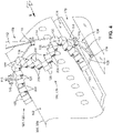
- FIGS 4-6 shown are two arrays 120 of treatment devices 126 supported by the upper treatment device support assembly 102, and two arrays 120 of treatment devices 126 supported by the lower treatment device support assembly 104. Also shown are the device actuation systems 200 interconnecting the treatment devices 126 of each array 120.
- Figures 4-5 show the treatment devices 126 positioned and oriented complementary to the local contour of the fuselage 306.
- the attachment pillars 112 are rotatable about the pillar pivot joints 110.
- the attachment arms 114 are rotatable about the arm pivot joints 116. The pivotability of the attachment pillars 112 and attachment arms 114 allows the arrays 120 of treatment device 126 to be positioned complementary to a variety of articles 300 of different sizes and shapes.
- the device actuation systems 200 are configured to translate and rotate the treatment devices 126 relative to each other in a manner maintaining each treatment device 126 at a predetermined distance and orientation relative to the local contour of an article surface 302 over which the treatment devices 126 are being moved while dispensing a treatment.
- the lower treatment device support assembly 104 includes a plurality of device frames 128 respectively of the plurality of treatment devices 126.
- Each device frame 128 is configured to support one or more device heads 150 which, in the configuration shown, are arranged in rows and columns within each device frame 128.
- the array 120 of device frames 128 includes an apex device frame 130 at the intersection of two device frame rows 136.
- Each device frame row 136 terminates at an end device frame 132, which is coupled to an attachment arm 114 via a device actuation system 200 that is coupled to an arm pivot joint 116.
- each device frame row 136 includes one or more intermediate device frames 134 between the apex device frame 130 and the end device frame 132.
- a treatment device support assembly may be provided with any number of intermediate device frames 134 between the apex device frame 130 and the end device frame 132, including a single intermediate device frame 134 between the apex device frame 130 and the end device frame 132.
- a treatment device support assembly may be devoid of intermediate device frames 134, and may include only a pair of end device frames 132 each coupled to an apex device frame 130 via a pair of device actuation systems 200.
- the device actuation systems 200 interconnecting the device frames 128 are configured to move the device frames 128 of the treatment devices 126 between an expanded configuration 122 and a contracted configuration 124 ( Figures 28-29 ), and to any configuration in between, to allow the treatment devices 126 to be repositioned and reoriented to match the local size and shape (e.g., curvature) of an article surface 302 ( Figure 4 ).
- the intermediate device frames 134 and the end device frame 132 respectively in the two device frame rows 136 are spaced farther apart from each other than in the contracted configuration 124 (e.g., Figures 28-29 ).
- the device frame rows 136 are non-parallel to each other.
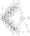
- the array 120 of treatment devices 126 has a V-shaped configuration.
- the treatment devices 126 may be arranged in any one of a wide variety of configurations, and are not limited to a V-shaped configuration.
- the device frame rows 136 in the contracted configuration 124 may be generally parallel to each other.
- at least one pair of treatment devices 126 are positioned in close side-by-side proximity to each other, similar to the arrangement shown in Figures 28-29 as described below.
- each of the device actuation systems 200 interconnecting the device frames 128 includes at least one gear system 202 ( Figures 8-11 ) and a drive rail 230 ( Figures 12-15 ).
- at least one gear system 202 is coupled to each device frame 128.
- each one of the end device frames 132 has a gear system 202 mounted to opposing lateral sides 154 of the end device frame 132.
- each one of the intermediate device frames 134 has a gear system 202 mounted to opposing lateral sides 154 of the intermediate device frame 134.
- the apex device frame 130 has a pair of gear systems 202 mounted to the same lateral side 154, and is devoid of gear systems 202 on the opposite lateral side 154 of the apex device frame 130.
- each of the end device frames 132 is coupled to an arm pivot joint 116 by a drive rail 230 extending from the gear system 202 mounted one of the lateral sides 154 of the end device frame 132.
- the gear system 202 on the opposite lateral side 154 of each end device frame 132 is coupled to the gear system 202 of an intermediate device frame 134 via a drive rail 230.
- each gear system 202 on the opposing lateral sides 154 of each intermediate device frame 134 is coupled to the gear system 202 of an immediately-adjacent intermediate device frame 134 via a drive rail 230.
- the gear systems 202 respectively of adjacent pairs of treatment devices 126 are respectively mounted to the lateral sides 154 that generally face each other, thereby allowing adjacent pairs of treatment devices 126 to be interconnected by a drive rail 230, and allowing the treatment devices 126 to be translated and rotated relative to each other such that at least a portion of the lateral sides 154 of the adjacent pair of treatment devices 126 directly face each other.
- a treatment band (not shown) dispensed by each treatment device 126 onto an article surface is capable of at least partially overlapping the treatment band (not shown) dispensed by an immediately adjacent treatment device 126, thereby avoiding lengthwise gaps (not shown) between adjacent treatment bands that would otherwise occur if the array 120 of treatment devices 126 were arranged in a non-overlappable manner.
- the arrangement shown in Figure 7 allows for the image band (not shown) printed by each inkjet printhead 152 onto the fuselage surface to be aligned in non-gapping and/or non-overlapping relation to the image band printed by an immediately adjacent inkjet printhead 152 as the treatment device system 100 moves the array of inkjet printheads 152 along the length of the fuselage 306.
- the aesthetic quality of the aircraft livery is improved relative to the quality of aircraft liveries applied using the above-described conventional methods.
- the treatment device system 100 includes a controller 182 ( Figure 8 ) for controlling the movement of the components of the upper and lower treatment device support assemblies 102, 104.
- the controller 182 controls the pivoting of the attachment pillars 112 about the pillar pivot joints 110, and the pivoting of the attachment arms 114 about the arm pivot joints 116 to allow the arrays 120 of treatment devices 126 to accommodate articles 300 of different sizes and shapes.
- the controller 182 controls the device actuation systems 200 interconnecting the treatment devices 126 in a manner to adjust the position and orientation of the treatment devices 126 relative to each other for accommodating the article shape.
- the upper and lower treatment device support assemblies 102, 104 may include one or more sensors 184 mounted to one or more of the device frames 128.
- the sensors 184 may be provided as imaging devices (e.g., cameras), laser scanners, or other metrology devices configured to sense the article surface 302.
- Each sensor 184 is configured to continuously scan the topography of the article surface 302 ( Figures 1-3 ) as the treatment devices 126 are moved over the article 300 ( Figures 1-3 ), and continuously generate surface data representative of the local contour of the article surface 302.
- one or more sensors 184 on each treatment device 126 continuously senses the distance between a dispensing side 158 of each treatment device 126 and the article surface 302, in addition to sensing the orientation of the treatment device 126 relative to the local contour of the article surface 302.
- the sensors 184 of each treatment device 126 continuously sense the orientation of a nominal dispensing direction 160 of the treatment device 126 relative to the local contour of the article surface 302.
- the nominal dispensing direction 160 of a treatment device 126 may be described as the direction along which a treatment is dispensed from a dispensing side 158 of the treatment device 126.
- the dispensing direction 160 is the direction along which the treatment is dispensed prior to any such pitch and/or yaw adjustment of the device heads 150.
- the sensors 184 ( Figure 8 ) of the treatment devices 126 continuously transmit surface data to the controller 182 ( Figure 2 ).
- the controller 182 processes the surface data provided by the sensors 184 and controls the device actuation systems 200 ( Figure 7 ) in a manner to continuously adjust the position of the treatment devices 126 ( Figure 7 ) to thereby maintain the dispensing side 158 ( Figure 8 ) or dispensing face of the treatment devices 126 within a tolerance band (e.g., ⁇ 0.010 inch) of a predetermined distance (e.g., up to 0.20 inch) from the article surface 302 ( Figures 1-3 ).
- a tolerance band e.g., ⁇ 0.010 inch
- a predetermined distance e.g., up to 0.20 inch
- the controller 182 controls the device actuation systems 200 in a manner to continuously adjust the orientation of the treatment devices 126 to thereby maintain the nominal dispensing direction 160 ( Figure 8 ) of each treatment device 126 within a predetermined tolerance band (e.g., ⁇ 5 degrees) of a desired orientation (e.g., locally normal or perpendicular) relative to the article surface 302.
- the controller 182 controls the operation of each gear system 202 in a manner to adjust the position and orientation of the treatment devices 126 relative to the article surface 302 as needed to maintain the treatment devices 126 complementary to the article surface 302 as the treatment devices 126 are moved over the article 300 while dispensing the treatment toward the article surface 302.
- the device frame 128 of each treatment device 126 has a dispensing direction 160 along which the treatment device 126 dispenses a treatment from a dispensing side 158 of the treatment device 126.
- treatment device 126 has an orthogonal shape, and the lateral sides 154 of the device frame 128 are parallel to the dispensing direction 160.
- a treatment device 126 may be provided with a non-orthogonal shape, and/or the lateral sides 154 may be non-parallel to the dispensing side 158 of the treatment device 126.
- the device frame 128 is configured to support a plurality of device heads 150.
- each of the device heads 150 may be provided as an inkjet printhead 152 configured to dispense ink (i.e., the treatment) along the dispensing direction 160.
- Each device frame 128 is configured to support one or more rows and/or one or more columns of inkjet printheads 152.
- the device heads 150 may be provided in alternative configurations, and are not limited to inkjet printheads 152, as mentioned above.
- FIGS 8-11 show a simplified version of a treatment device 126 having a single gear system 202.
- each treatment device 126 in an array 120 may have two gear systems 202, including one gear system 202 on one lateral side 154 of the device frame 128, and another gear system 202 on an opposite lateral side 154 of the device frame 128.
- the apex device frame 130 in an array 120 has two gear systems 202 on the same lateral side 154.
- the gear system 202 of the device actuation system 200 includes a first drive gear 204, a coupler rail 224, a second drive gear 208, and a coupler gear 214.
- the first drive gear 204, the second drive gear 208, and the coupler gear 214 are independently rotatably driven respectively by a first drive gear motor 206, a second drive gear motor 210, and a coupler gear motor 216, under control of the controller 182 ( Figure 2 ).
- the first drive gear motor 206, the second drive gear motor 210, and the coupler gear motor 216 are electric servomotors.
- the first drive gear 204 is rotatably mounted to the treatment device 126. More specifically, the first drive gear motor 206 is mounted to a lateral side 154 of the device frame 128 in an interior of the device frame 128.
- the first drive gear motor 206 includes a shaft (not shown) that extends to the exterior of the device frame 128 through a hole (not shown) in the lateral side 154.
- the first drive gear 204 is mounted on the shaft of the first drive gear motor 206.
- the coupler rail 224 is slidably mounted to the device frame 128 of the treatment device 126.
- the coupler rail 224 is slidably mounted to the lateral side 154 in the interior of the device frame 128 via a coupler rail slide mechanism 238.
- the coupler rail slide mechanism 238 comprises a slide channel formed in the coupler rail 224, and which slides along a slide rail located on the lateral side 154 of the device frame 128.
- the coupler rail slide mechanism 238 may be provided in any one of a variety of alternative configurations allowing sliding motion of the coupler rail 224 relative to the device frame 128.
- the coupler gear 214 is rotatably mounted to the treatment device 126. More specifically, the coupler gear motor 216 is mounted to the device frame 128 in an interior of the device frame 128. The coupler gear motor 216 may be supported by a bracket (not shown) mounted to the lateral side 154 of the device frame 128. The coupler gear motor 216 includes a shaft (not shown) upon which the coupler gear 214 is mounted. The coupler gear 214 has gear teeth 228 that are in continuous meshing engagement with the rail teeth 226 of the coupler rail 224.
- the second drive gear 208 is rotatably mounted to the coupler rail 224. More specifically, the second drive gear motor 210 is mounted to the coupler rail 224.
- the second drive gear motor 210 includes a shaft (not shown) that extends to the exterior of the device frame 128 through a hole (not shown) in the coupler rail 224, and through a frame slot 156 in the lateral side 154.
- the second drive gear 208 is mounted on the shaft of the second drive gear motor 210.
- a drive rail 230 is located between the first drive gear 204 and the second drive gear 208 of the treatment device 126.
- the first drive gear 204 and the second drive gear 208 have gear teeth 228 configured to engage or mesh with the rail teeth 226 of the drive rail 230.
- a plurality of the drive rails 230 interconnect adjacent pairs of the treatment devices 126. Each drive rail 230 is captured between the first drive gear 204 and the second drive gear 208 respectively of the treatment device 126 of each adjacent pair.
- the coupler gear 214 is rotated to move the coupler rail 224 in a manner moving the second drive gear 208 toward or away from the first drive gear 204, to thereby maintain the second drive gear 208 in continuous engagement with the drive rail 230 against the first drive gear 204.
- the drive rail 230 has opposing rail sides 232 that define a rail width.
- the first drive gear 204 and the second drive gear 208 each have a pair of gear sides 218.
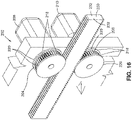
- the gear sides 218 of the first drive gear 204 and the second drive gear 208 each have circumferential ridges 220 that are spaced apart by a distance that is approximately equal to (i.e., but not less than) the rail width.
- the circumferential ridges 220 are sized to extend over the rail sides 232, to thereby maintain the drive rail 230 in alignment with the first drive gear 204 and the second drive gear 208.
- the circumferential ridges 220 prevent the drive rail 230 from moving laterally out of alignment with the first drive gear 204 and second drive gear 208.
- the circumferential ridges 220 may be integrated into the first drive gear 204 and the second drive gear 208, or each circumferential ridge 220 may be part of a disc-shaped member (not shown) that is mounted against the gear sides 218 of the first drive gear 204 and second drive gear 208.
- the drive rail 230 is straight. However, in other examples not shown, the drive rail 230 may be slightly curved. Likewise, the coupler rail 224 may be provided in a slightly curved arrangement as an alternative to the straight shape shown in the figures. In the example shown, the first drive gear 204, the coupler rail 224, the coupler gear 214, and the second drive gear 208 have outer diameters that are equivalent to each other. However, in other examples, the first drive gear 204, the coupler rail 224, the coupler gear 214 may have different outer diameters.
- the first drive gear 204, the second drive gear 208, and the drive rail 230 are external to the device frame 128.
- the coupler rail 224 and the coupler gear 214 are internal to the device frame 128, and are non-protruding from the lateral side 154 of the device frame 128.
- mounting the coupler rail 224 and coupler gear 214 inside the treatment device 126 provides for a compact form factor, allowing an array 120 of treatment devices 126 to be packaged in close proximity to each other.
- the drive rail 230 defines a plane of rotation 236 during actuation (e.g., rotation) of the treatment device 126.
- the plane of rotation 236 is parallel to the dispensing direction 160 ( Figure 8 ).
- the coupler gear 214 and the coupler rail 224 are located inside the inside the device frame 128, and are therefore outside of the plane of rotation 236, which advantageously increases the angular range of rotation of the treatment device 126, relative to a reduced angular range of rotation of a treatment device 126 in an arrangement (not shown) in which the coupler gear 214 and the coupler rail 224 protrude into the plane of rotation 236.
- the coupler rail 224 and the coupler gear 214 may be external to the device frame 128, and/or the coupler rail 224 and the coupler gear 214 may protrude through the plane of rotation 236.
- the gear system 202 is couplable to the lateral side 154 of the device frame 128 in a manner such that the coupler rail 224 is generally parallel to the dispensing direction 160 ( Figure 8 ) of the treatment device 126, and perpendicular to the dispensing side 158 ( Figure 8 ) of the treatment device 126.
- the gear system 202 may be configured such that the coupler rail 224 is non-parallel to the dispensing direction 160 of the treatment device 126.
- the first drive gear 204, the second drive gear 208, and the coupler gear 214 have rotational axes 222 that are parallel to each other, and are oriented in the same direction.
- the rail teeth 226 of the coupler rail 224 may be located on a side of the coupler rail 224 opposite the lateral side 154 of the device frame 128, and the rotational axis 222 of the coupler gear 214 may be oriented perpendicular to the rotational axes 222 of the first drive gear 204 and the second drive gear 208 to enable the gear teeth 228 of the coupler gear 214 to engage the rail teeth 226 of the coupler rail 224.
- Figure 9 shows a reference coordinate system 186 having an x-axis, a y-axis, and a z-axis.
- the device actuation system 200 is configured to translate and rotate the treatment device 126 along a direction parallel to the x-z plane of the reference coordinate system 186.
- the drive rail 230 has a drive rail axis 234 extending along a lengthwise direction of the drive rail 230.
- the first drive gear 204 and the second drive gear 208 each have a rotational axis 222 ( Figure 11 ).
- the gear system 202 includes a first-second drive gear axis 212 that passes through the rotational axis 222 of the first drive gear 204 and the rotational axis 222 of the second drive gear 208.
- the gear system 202 is coupled to the treatment device 126 such that when the drive rail axis 234 is perpendicular to the dispensing direction 160 ( Figure 8 ) of the treatment device 126, the first-second drive gear axis 212 is parallel to the dispensing direction 160.
- the dispensing direction 160 is vertically upward, the first drive gear 204 and the second drive gear 208 are vertically aligned.
- the coupler gear motor 216 is operated by the controller 182 in a manner to rotate the coupler gear 214 for moving the coupler rail 224 in a manner maintaining the second drive gear 208 in continuous engagement with the drive rail 230 against the first drive gear 204.
- the first drive gear motor 206 and the second drive gear motor 210 are respectively operated by the controller 182 in a manner to respectively rotate the first drive gear 204 and the second drive gear 208 to cause translation and/or rotation of the treatment device 126 relative to the drive rail 230.
- the first drive gear motor 206 and the second drive gear motor 210 are operated in a manner to position and orient the treatment device 126 complementary to the contour of the article surface 302.
- the coupler gear 214 is rotated in a manner to maintain the gear teeth 228 of the second drive gear 208 in continuous engagement with the rail teeth 226 on one side of the drive rail 230, while the rail teeth 226 on the opposite side of the drive rail 230 are in continuous engagement with the gear teeth 228 of the first drive gear 204.
- the controller 182 coordinates the timing and direction of rotation of the first drive gear motor 206, the second drive gear motor 210, and the coupler gear motor 216 in a manner to adjust the position and orientation of the treatment device 126 relative to the article surface 302.
- actuation of a treatment device 126 is performed by rotating the first drive gear 204 and the second drive gear 208 of the treatment device 126 according to one of two rotation modes.
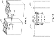
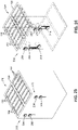
- Figures 17-18 illustrate the left-hand treatment device and the right-hand treatment device in a home position prior to translation of the left-hand treatment device ( Figures 19-20 ) relative to the right-hand treatment device, and prior to rotation of the left-hand treatment device ( Figures 21-22 ) relative to the right-hand treatment device.
- Figures 19-20 illustrate a mode of operation in which the first drive gear 204 and the second drive gear 208 of the left-hand treatment device are synchronously rotated at the same speed and in opposite directions, to thereby cause translation of the left-hand treatment device relative to the drive rail 230.
- the synchronous rotation of the first drive gear 204 and the second drive gear 208 at the same speed and in opposite directions causes translation of the left-hand treatment device back and forth along the lengthwise direction of the drive rail 230.
- the first drive gear 204 and the second drive gear 208 are counter-rotated at the same speed.
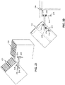
- Figures 21-22 illustrate a mode of operation in which the first drive gear 204 and the second drive gear 208 of the left-hand treatment device are differentially rotated at different speeds and in the same or opposite directions, to at least cause rotation of the left-hand treatment device relative to the drive rail 230.
- the first drive gear 204 and the second drive gear 208 are differentially rotatable at different speeds in a manner causing a combination of rotation and translation of the treatment device 126 relative to the drive rail 230.
- rotation of the left-hand treatment device may be achieved by rotating either the first drive gear 204 or the second drive gear 208, while a remaining one of the first drive gear 204 and the second drive gear 208 is non-rotated or is static.
- FIG. 23-24 shown is an example of a treatment device 126 having two gear systems 202 mounted on a common lateral side 154 of the device frame 128.
- the device frame 128 in Figures 23-24 is the apex device frame 130 in the array 120 shown in Figure 7 .
- the first drive gear 204 and the second drive gear 208 of each gear system 202 is configured to receive a drive rail 230 that is independent of the drive rail 230 received within the first drive gear 204 and the second drive gear 208 of the other gear system 202.
- the drive rail 230 of each gear system 202 is configured to interconnect with the gear system 202 of an adjacent treatment device 126.
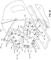
- FIG. 25-26 shown is an example of the treatment device system 100 of Figure 1 positioned over the nose section 310 of the fuselage 306 and illustrating the treatment devices 126 located and oriented complementary to the compound curvature of the nose section 310.
- the treatment devices 126 form an array 120 in the above-mentioned expanded configuration 122 (e.g., a V-shaped configuration).
- the device actuation systems 200 interconnecting the treatment devices 126 have moved the apex device frame 130 and the intermediate device frames 134 along the dispensing direction 160 of the respective treatment devices 126, such that the dispensing face of each treatment device 126 is in close proximity to the surface of the nose section 310.
- the device actuation systems 200 have oriented the treatment devices 126 such that the dispensing direction 160 ( Figure 8 ) of each treatment device 126 is locally perpendicular or normal to the surface of the nose section 310, to facilitate livery printing onto the nose section 310 of the fuselage 306.
- each of the two arrays 120 of treatment devices 126 have been relocated and reoriented into an arrangement similar to the arrangement shown in Figures 25-26 .
- each of the two arrays 120 of treatment devices 126 respectively on opposite sides of the vertical tail 314 are in a semi-contracted configuration to allow each array 120 of treatment devices 126 to fit between the vertical tail 314 and one of the horizontal tails 316, thereby facilitating livery printing on the tail section 312 of the fuselage 306.
- the components of the treatment device system 100 may be operated in a manner to position one or more arrays 120 of treatment devices 126 against other areas of the aircraft 304, in addition to the fuselage 306.
- the treatment device system 100 may be operated in a manner to position an array 120 of treatment devices 126 on each of opposing sides of the vertical tail 314 for livery printing, and/or on other areas of the aircraft 304.
- the device actuation systems 200 facilitate compound movements of translation and rotation of treatment devices 126 while occupying a relatively small amount of space.
- the relatively small amount of space occupied by the device actuation systems 200 allows for the integration of multiple treatment devices 126 within an array 120, enabling automated processing (e.g., livery printing) of large articles 300 (e.g., commercial aircraft 304) in a precise manner and in a significantly reduced amount of time relative to conventional methods.
- each treatment device 126 is configured to dispense a treatment toward an article surface 302.
- the method 500 includes supporting one or more device heads 150 from at least one of a plurality of device frames 128 respectively associated with a plurality of the treatment devices 126, as shown in Figures 7-8 .
- each device frame 128 has at least one gear system 202 coupled to the device frame 128, and each gear system 202 has a first drive gear 204, a second drive gear 208, a coupler gear 214, and a coupler rail 224.
- the end device frames 132 and the intermediate device frame 134 each have a gear system 202 mounted to each of opposing lateral sides 154 of the device frame 128.
- Step 502 of the method 500 comprises rotating the first drive gear 204 and the second drive gear 208, which are engaged to opposite sides of a drive rail 230, to thereby cause translation and/or rotation of a treatment device 126 relative to the drive rail 230.
- the first drive gear 204 is mounted to the treatment device 126
- the second drive gear 208 is mounted to the coupler rail 224.
- the coupler rail 224 is slidably mounted to the treatment device 126.
- the coupler rail 224 is engaged to the coupler gear 214, which is mounted to the treatment device 126, as described above.
- Step 502 of rotating the first drive gear 204 and the second drive gear 208 includes independently rotating, under control of the controller 182, the first drive gear 204 and the second drive gear 208 respectively via the first drive gear motor 206 and the second drive gear motor 210.
- the method includes independently rotating the coupler gear 214 via the coupler gear motor 216, which is also controlled by the controller 182.
- the first drive gear motor 206 and the coupler gear motor 216 are mounted to the device frame 128, and the second drive gear motor 210 is mounted to the coupler rail 224.
- Step 502 of rotating the first drive gear 204 and the second drive gear 208 of a treatment device 126 additionally comprises rotating the first drive gear 204 and the second drive gear 208 according to one of two rotation modes.
- One rotation mode includes synchronously rotating the first drive gear 204 and the second drive gear 208 at the same speed and in opposite directions to cause translation of the treatment device 126 relative to the drive rail 230.
- the treatment device 126 is translated back and forth along the lengthwise direction of the drive rail 230 during synchronized rotation of the first drive gear 204 and the second drive gear 208.
- Another rotation mode includes differentially rotating the first drive gear 204 and the second drive gear 208 at different speeds and in the same or opposite directions to at least cause rotation of the treatment device 126 relative to the drive rail 230.
- the process of differentially rotating the first drive gear 204 and the second drive gear 208 of a treatment device 126 comprises differentially rotating the first drive gear 204 and the second drive gear 208 at different speeds in a manner causing a combination of rotation and translation of the treatment device 126 relative to the drive rail 230.
- differentially rotating the first drive gear 204 and the second drive gear 208 comprises rotating either the first drive gear 204 or the second drive gear 208, while the remaining first drive gear 204 or the second drive gear 208 is static.
- Step 504 of the method 500 comprises rotating the coupler gear 214 to move the coupler rail 224 in a manner to maintain the second drive gear 208 in continuous engagement with the drive rail 230.
- the drive rail 230 is captured between the first drive gear 204 and the second drive gear 208. Differential rotation of the first drive gear 204 and the second drive gear 208 causes rotation of the treatment device 126 relative to the drive rail 230. As shown in Figures 12-15 and described above, rotation of the treatment device 126 relative to the drive rail 230 requires continuous adjustment of the distance of the second drive gear 208 from the first drive gear 204 in order to maintain the second drive gear 208 (and first drive gear 204) in continuous engagement with the drive rail 230.
- the force applied by the second drive gear 208 against the drive rail 230 maintains the rail teeth 226 on the opposite side of the drive rail 230 in continuous engagement with the gear teeth 228 of the first drive gear 204.
- the method 500 includes maintaining the drive rail 230 in alignment with the first drive gear 204 and second drive gear 208 via a pair of circumferential ridges 220 respectively on a pair of gear sides 218 of the first drive gear 204 and the second drive gear 208.
- the circumferential ridges 220 on each gear side 218 of the first drive gear 204 and the second drive gear 208 extend over the rail sides 232, which prevents the drive rail 230 for moving out of alignment with the first drive gear 204 and the second drive gear 208.
- the operation of the treatment device system 100 comprises operating a plurality of device actuation systems 200 as a means to locate and orient a plurality of treatment devices 126.
- step 502 of rotating the first drive gear 204 and the second drive gear 208 comprises rotating the first drive gear 204 and the second drive gear 208 of at least one treatment device 126 of at least one adjacent pair of treatment devices 126 interconnected by a drive rail 230, thereby causing translation and/or rotation of the pair of treatment devices 126 relative to each other.
- the treatment devices 126 are actuated relative to each other in a manner to maintain each treatment device 126 at a predetermined spacing and orientation relative to an article surface 302, while the treatment devices 126 are moved over the article 300.
- the method 500 comprises supporting the plurality of device frames 128 as an array 120, wherein each adjacent pair of device frames 128 is interconnected by a drive rail 230 located between the first drive gear 204 and the second drive gear 208 of the device frames 128.
- the method includes rotating the first drive gear 204, the second drive gear 208, and the coupler gear 214 respectively of the plurality of devices frame in a manner to move the array 120 between an expanded configuration 122 and a contracted configuration 124, and any configuration therebetween, to facilitate conforming the treatment devices 126 to the local geometry of an article surface 302.
- the method 500 comprises supporting at least one array 120 of treatment devices 126 from a treatment device support assembly 102, 104 having a pair of attachment pillars 112, each pivotably coupled to a pair of attachment arms 114.
- the opposite ends of each attachment arm 114 are coupled respectively to opposite ends of an array 120 of treatment devices 126.
- the treatment device system 100 includes an upper treatment device support assembly 102 and a lower treatment device support assembly 104 each having arrays 120 of treatment devices 126 in side-by-side arrangement, as described above.
- the method includes pivoting the attachment arms 114 relative to each other, and in coordination with the operation of the device actuation systems 200 in a manner to move each array 120 of treatment devices 126 between an expanded configuration 122 and a contracted configuration 124, to thereby position and orient each treatment device 126 complementary to the local contour of an article surface 302, as the overhead gantry 172 and the pit gantry 178 respectively move the upper treatment device support assembly 102 and the lower treatment device support assembly 104 along the lengthwise direction of the article 300 (e.g., fuselage 306) being processed.
- the article 300 e.g., fuselage 306
- the method 500 additionally includes dispensing a treatment from one or more device heads 150 of the treatment devices 126.
- a treatment may be dispensed from the device heads 150 while the treatment devices 126 are moved over the article 300.
- a treatment may be dispensed from the device heads 150 while the device actuation systems 200 continuously adjust the position and orientation of the treatment devices 126 relative to the article surface 302 as the treatment devices 126 are moved over the article 300.
- Treatment may also be dispensed from the device heads 150 while the treatment devices 126 are stationary relative to the article surfaces 302.
- the dispensing of the treatment from the device heads 150 may include dispensing a treatment from device heads 150 configured as inkjet printheads 152.
- the dispensing of the treatment may include dispensing ink from the inkjet printheads 152.
- the ink may be provided in a variety of compositions including, but not limited to, a primer, a paint, a clear coat, a sealant, or any one of a variety of other substances capable of being dispensed from an inkjet printhead 152.
- the inkjet printheads 152 may dispense ink for printing an aircraft livery on a fuselage 306, as shown in the example of Figures 1-5 and 25-28 .
- the dispensing of treatment from the treatment devices 126 may include dispensing substances such solvents, adhesives, lubricants, abrasive particles, or any one a variety of other types of gas, liquid, semi-solid, or solid substances. Even further, the dispensing of treatment from the treatment devices 126 may include emitting radiation from the treatment devices 126 for performing any one of a variety of functions, such as curing an article 300 formed of composite (e.g., graphite-epoxy) material.
- composite e.g., graphite-epoxy
Landscapes
- Engineering & Computer Science (AREA)
- Manufacturing & Machinery (AREA)
- General Engineering & Computer Science (AREA)
- Human Computer Interaction (AREA)
- Physics & Mathematics (AREA)
- General Physics & Mathematics (AREA)
- Automation & Control Theory (AREA)
- Mechanical Engineering (AREA)
- Spray Control Apparatus (AREA)
- Transportation (AREA)
- Aviation & Aerospace Engineering (AREA)
Abstract
Description
- The present disclosure relates generally to actuation systems and, more particularly, to a mechanical actuation system for actuating one or more treatment devices for treating contoured surfaces.
- The painting of an aircraft is a challenging process due to the large amount of surface area and unique geometry of aircraft surfaces. For example, the nose and tail of an aircraft are typically highly contoured, which presents challenges in applying coatings in a precise manner. Adding to the challenge are complex paint schemes associated with an aircraft livery. For example, the livery of an airline may include images or designs that have complex geometric shapes and color combinations. In addition, an aircraft livery may include the name and logo of the airline, which may be applied to different locations on the aircraft such as the fuselage and the vertical tail. The process of applying the livery to the aircraft surfaces must be carried out with a high level of precision to meet aesthetic requirements, and to ensure that the coating thickness is within desired tolerances to meet aircraft performance (e.g., weight) requirements.
- One method of painting an aircraft involves the use of individual robotic devices. Each robotic device includes an end effector mounted on a robotic arm. The robotic arm of each robotic device moves the end effector over the aircraft surfaces while the end effector dispenses any one of a variety of different paint colors, such as for applying an aircraft livery. Although the use of robotic devices reduces the amount of time required for aircraft painting relative to conventional manual methods that involve masking, painting, and demasking, the use of a single end effector on each robotic device results in a relative lengthy painting process.
- As can be seen, there exists a need in the art for a system for interconnecting an array of treatment devices for dispensing a treatment (e.g., paint) as the array is moved over an article surface, and which allows for the continuous repositioning of each treatment complementary to the changing contours of the article surfaces, to thereby enable precise application of coatings (e.g., an aircraft livery) in a reduced amount of time relative to conventional methods. Ideally, the actuation system has a compact arrangement to allow for relatively close spacing of the treatment devices in the array.
- The above-noted needs associated with interconnecting treatment devices are addressed by the presently-disclosed device actuation system for actuating a treatment device. The device actuation system includes a first drive gear rotatably mountable to the treatment device, a coupler rail slidably mountable to the treatment device, a second drive gear rotatably mountable to the coupler rail, and a coupler gear rotatably mountable to the treatment device and engageable with the coupler rail. In addition, the device actuation system includes a drive rail locatable between the first drive gear and the second drive gear of the gear system. The coupler gear is rotatable to move the coupler rail in a manner maintaining the second drive gear in continuous engagement with the drive rail against the first drive gear. The first drive gear and the second drive gear are rotatable in a manner causing at least one of translation and rotation of the treatment device relative to the drive rail.
- Also disclosed is a treatment device support assembly for actuating a plurality of treatment devices relative to each other for treating an article surface of an article. The treatment device support assembly includes a plurality of device actuation systems, each configured to interconnect an adjacent pair of treatment devices. Each device actuation system includes a gear system couplable to each treatment device of the adjacent pair of treatment devices. The gear system of each treatment device includes a first drive gear rotatably mountable to the treatment device, a coupler rail slidably mountable to the treatment device, a second drive gear rotatably mountable to the coupler rail, and a coupler gear rotatably mountable to the treatment device and engageable with the coupler rail. The device actuation system further includes a drive rail configured to interconnect the adjacent pair of treatment devices, and is locatable between the first drive gear and the second drive gear of each treatment device of the adjacent pair of treatment devices. For each treatment device of the adjacent pair of treatment devices, the coupler gear is rotatable to move the coupler rail in a manner maintaining the second drive gear in continuous engagement with the drive rail against the first drive gear. In addition, the first drive gear and the second drive gear are rotatable in a manner causing at least one of translation and rotation of the treatment device relative to the drive rail.
- Also disclosed is a method of actuating at least one treatment device. The method includes rotating a first drive gear and a second drive gear engaged to opposite sides of a drive rail to cause at least one of translation and rotation of a treatment device relative to the drive rail. The first drive gear is mounted to the treatment device, the second drive gear is mounted to a coupler rail slidably mounted to the treatment device, and the coupler rail is engaged to a coupler gear mounted to the treatment device. The method includes rotating the coupler gear to move the coupler rail in a manner maintaining the second drive gear in continuous engagement with the drive rail.
- The features, functions and advantages that have been discussed can be achieved independently in various examples of the present disclosure or may be combined in yet other examples, further details of which can be seen with reference to the following description and drawings below.
- These and other features of the present disclosure will become more apparent upon reference to the drawings wherein like numbers refer to like parts throughout and wherein:
-
Figure 1 is a perspective view of an example of a treatment device system comprising a plurality of treatment devices supported by a treatment device support assembly having a plurality of device actuation systems for repositioning the treatment devices complementary to the contour of a fuselage as the treatment device system is moved along the lengthwise direction of the fuselage during the application of a treatment to the fuselage surfaces; -
Figure 2 is a side view of the treatment device system and fuselage ofFigure 1 ; -
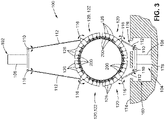
Figure 3 is a sectional view taken along line 3-3 ofFigure 2 , and illustrating an upper treatment device support assembly and a lower treatment device support assembly, each supporting a plurality of treatment devices surrounding the fuselage; -
Figure 4 is a magnified view of the encircled region identified by reference numeral 4 ofFigure 2 , and illustrating a plurality of treatment devices interconnected by a plurality of device actuation systems; -
Figure 5 is an aft perspective view of the fuselage and the treatment device system taken alongline 5 ofFigure 4 , and illustrating the treatment devices interconnected by the plurality of device actuation systems; -
Figure 6 is a perspective view of an example of a lower treatment device support assembly supporting a pair of frame arrays, each comprising a plurality of treatment devices interconnected by a plurality of device actuation systems; -
Figure 7 is a perspective view of an example of an array of treatment devices interconnected by a plurality of device actuation system, and illustrating the array in an expanded configuration that is complementary to the contour of the article surface; -
Figure 8 is a perspective view of an example of a treatment device comprising a device frame supporting a plurality of device heads, and further illustrating a gear system coupled to the device frame; -
Figure 9 is a perspective view of the treatment device ofFigure 8 showing in hidden lines a first drive gear motor, a second drive motor, a coupler rail, a coupler gear motor, and a coupler gear of the gear system; -
Figure 10 is a side view of the treatment device ofFigure 8 ; -
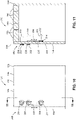
Figure 11 is a sectional view taken along line 11-11 ofFigure 10 , and illustrating the gear system which comprises a first drive gear driven by the first drive gear motor, a coupler rail slidably mounted to the device frame, a second drive gear driven by the second drive gear motor and mounted to the coupler rail, and a couple gear rotatably mounted to the treatment device and engaged to the couple rail; -
Figure 12 is a magnified perspective view of the encircled region of the gear system identified by reference numeral 10 ofFigure 8 , and illustrating a drive rail captured between the first drive gear and the second drive gear, and showing the drive rail axis oriented perpendicular to a first-second drive gear axis; -
Figure 13 is a perspective view of the gear system taken alongline 13 ofFigure 12 , and illustrating the second drive gear motor mounted to the coupler rail, which is slidably engaged to the device frame via a coupler rail slide mechanism; -
Figure 14 is a perspective view of the device actuation system ofFigure 12 showing the second drive gear moved away from the first drive gear, and showing the drive rail axis oriented non-perpendicular to the first-second drive gear axis; -
Figure 15 is a perspective view of the gear system taken alongline 15 ofFigure 14 showing the coupler rail and the second drive gear moved away from the first drive gear; -
Figure 16 is a perspective view of an example of the gear system in which the first drive gear and the second drive gear each have a pair of circumferential ridges for maintaining the drive rail in alignment with the first drive gear and the second drive gear; -
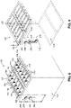
Figure 17 is a perspective view of a pair of treatment devices interconnected by a device actuation system and illustrating the treatment devices spaced apart from each other in a home position; -
Figure 18 is a front view of the treatment devices ofFigure 17 ; -
Figure 19 is a perspective view of the treatment devices translated into close proximity to each other after the first drive gear and the second drive gear of one of the treatment devices are synchronously rotated at the same speed and in opposite directions to cause translation of the treatment device relative to the drive rail; -
Figure 20 is a front view of the treatment devices ofFigure 19 ; -
Figure 21 is a perspective view of the treatment devices after rotation relative to each other after the first drive gear and the second drive gear of one of the treatment devices are differentially rotated at different speeds and in the same or opposite directions to at least cause rotation of the treatment device relative to the drive rail; -
Figure 22 is a front view of the treatment devices ofFigure 21 ; -
Figure 23 is a perspective view of an example of a treatment device having a pair of gear systems respectively incorporated into opposite lateral sides of the treatment device; -
Figure 24 is a perspective view of treatment device ofFigure 23 showing in hidden lines the first drive gear motor, the second drive motor, the coupler rail, the coupler gear motor, and the coupler gear of each gear system; -
Figure 25 is a perspective view of an example of the treatment device system positioned over the nose section of the fuselage; -
Figure 26 is a magnified view of the encircled region identified byreference numeral 26 ofFigure 25 , and illustrating the treatment devices positioned complementary to the curvature of the nose section; -
Figure 27 is a perspective view of an example of the treatment device system positioned at the tail section of the fuselage; -
Figure 28 is a magnified view of the encircled region identified byreference numeral 28 ofFigure 27 , and illustrating the treatment devices positioned complementary to the contour of the tail section in the area between the vertical tail and horizontal tail; -
Figure 29 is a flowchart of a method of actuating a treatment device. - Referring now to the drawings, which illustrate preferred and various examples of the disclosure, shown in
Figures 1-3 is an example of atreatment device system 100 for treating the article surfaces 302 of anarticle 300. Thetreatment device system 100 includes an upper treatmentdevice support assembly 102 and a lower treatmentdevice support assembly 104 for supporting one ormore treatment devices 126. In the example shown, thearticle 300 is afuselage 306 of an aircraft 304 having avertical tail 314 and a pair ofhorizontal tails 316. Thefuselage 306 is shown supported on thefloor 174 of atreatment facility 170 using fuselage support stands 308. - Each treatment
device support assembly Figures 4-6 ) for actuating at least onetreatment device 126. As described in greater detail below, eachdevice actuation system 200 is configured to translate and/or rotate at least onetreatment device 126. In one example, eachdevice actuation system 200 is configured to position atreatment device 126 relative to the changing contours of anarticle surface 302 over which thetreatment device 126 is being moved. In the example ofFigures 8-9 , eachtreatment device 126 includes adevice frame 128, and eachtreatment device 126 has one or more device heads 150 which are shown arranged in rows and/or columns, and which are supported by thedevice frame 128. - The treatment devices 126 (e.g., the device heads 150) are configured to dispense a treatment toward and/or onto an
article surface 302. The treatment may be a coating, such as a primer, a paint, a clear coat, or a sealant. For painting anarticle 300 such as thefuselage 306 shown inFigure 1-3 , thetreatment devices 126 are configured as inkjet printheads 152 (Figure 7 - e.g., piezoelectric printheads or thermal printheads) each configured to precisely dispense ink onto the surfaces of thefuselage 306 as thetreatment devices 126 are moved along thefuselage 306 for printing an aircraft livery. In other examples, thetreatment devices 126 may be configured to dispense other types of treatments or substances, such as a solvent, an adhesive, a lubricant, abrasive particles, or any type of gas, liquid, semi-solid, or solid (e.g., particles) substance. In still further examples, thetreatment devices 126 may be configured to emit radiation (e.g., electromagnetic radiation) for performing any one of a variety of operations on anarticle surface 302. - Although described in the context of treating the surfaces of a
fuselage 306, thetreatment device system 100 may be implemented for treating any one of a variety of different types ofarticles 300, and is not limited to treating an aircraft 304. For example, thetreatment device system 100 may be implemented for treating vehicles, such as ships, trains, or other ground-based motor vehicles such as trucks and automobiles. In addition, thetreatment device system 100 may be implemented for treating stationary objects including, but not limited to, buildings, architectural objects, walls, and/or any one of a variety of other types of structures, systems, subsystems, assemblies, or subassemblies. - In
Figures 1-3 , as mentioned above, thetreatment device system 100 includes an upper treatmentdevice support assembly 102 and a lower treatmentdevice support assembly 104, each of which has a plurality ofdevice actuation systems 200 for repositioning thetreatment devices 126 complementary to the contours of an article 300 (e.g., a fuselage 306) as thetreatment device system 100 is moved over the article 300 (e.g., along a lengthwise direction of a fuselage 306) during the application of a treatment to the article surfaces 302. Thedevice actuation systems 200 interconnect thetreatment devices 126. In addition, thedevice actuation systems 200 are configured to actuate thetreatment devices 126 relative to each other. As described in greater detail below, eachdevice actuation system 200 is configured to translate and rotate an adjacent pair oftreatment devices 126 relative to each other in a manner to maintain eachtreatment device 126 at a predetermined spacing and orientation relative to the local contour of anarticle surface 302 as thetreatment devices 126 are moved over thearticle 300. - In the example of
Figures 1-3 , the upper treatmentdevice support assembly 102 includes acentral pillar 106 coupled to an overhead gantry 172 (Figures 1-3 ). Thefuselage 306 is oriented parallel to the lengthwise direction of theoverhead gantry 172, allowing the upper treatmentdevice support assembly 102 to move thetreatment devices 126 along the length of thefuselage 306 from thenose section 310 section to thetail section 312. Asupport structure base 108 is shown coupled to thecentral pillar 106. On each of opposing sides of thesupport structure base 108 is a pillar pivot joint 110 coupling anattachment pillar 112 to thesupport structure base 108. At the lower end of eachattachment pillar 112 is an arm pivot joint 116 coupling a pair ofattachment arms 114 to theattachment pillar 112. The ends of theattachment arms 114 are respectively coupled via arm pivot joints 116 to opposite sides of anarray 120 oftreatment devices 126 which, as indicated above, are interconnected by a plurality ofdevice actuation systems 200. In the example shown, the upper treatmentdevice support assembly 102 supports twoarrays 120 oftreatment devices 126 in side-by-side arrangement. - In
Figures 1-3 , the lower treatmentdevice support assembly 104 is configured similar to the upper treatmentdevice support assembly 102. For example, the lower treatmentdevice support assembly 104 includes acentral pillar 106 which is supported on apit gantry 178 mounted in apit 180 that extends along a lengthwise direction below thefloor 174 in parallel to theoverhead gantry 172. As shown inFigures 2-3 , asupport structure base 108 is mounted on the upper end of thecentral pillar 106. A pair of pillar pivot joints 110 on opposite sides of thesupport structure base 108 respectively couple a pair ofattachment pillars 112 to thesupport structure base 108. Theattachment pillars 112 extend upwardly through a pair offloor openings 176. At the upper end of eachattachment pillar 112 is an arm pivot joint 116 coupling a pair ofattachment arms 114 to theattachment pillar 112. The ends of the pair ofattachment arms 114 extending from eachattachment pillar 112 are coupled to opposite sides of anarray 120 oftreatment devices 126. The lower treatmentdevice support assembly 104 supports twoarrays 120 oftreatment devices 126 in side-by-side arrangement. - Referring to
Figures 4-6 , shown are twoarrays 120 oftreatment devices 126 supported by the upper treatmentdevice support assembly 102, and twoarrays 120 oftreatment devices 126 supported by the lower treatmentdevice support assembly 104. Also shown are thedevice actuation systems 200 interconnecting thetreatment devices 126 of eacharray 120.Figures 4-5 show thetreatment devices 126 positioned and oriented complementary to the local contour of thefuselage 306. Toward this end, theattachment pillars 112 are rotatable about the pillar pivot joints 110. In addition, theattachment arms 114 are rotatable about the arm pivot joints 116. The pivotability of theattachment pillars 112 andattachment arms 114 allows thearrays 120 oftreatment device 126 to be positioned complementary to a variety ofarticles 300 of different sizes and shapes. Thedevice actuation systems 200 are configured to translate and rotate thetreatment devices 126 relative to each other in a manner maintaining eachtreatment device 126 at a predetermined distance and orientation relative to the local contour of anarticle surface 302 over which thetreatment devices 126 are being moved while dispensing a treatment. - Referring to
Figure 7 , shown is asingle array 120 oftreatment devices 126 of the lower treatmentdevice support assembly 104. Thearray 120 is supported on opposite ends respectively by the pair ofattachment arms 114. The lower treatmentdevice support assembly 104 includes a plurality of device frames 128 respectively of the plurality oftreatment devices 126. Eachdevice frame 128 is configured to support one or more device heads 150 which, in the configuration shown, are arranged in rows and columns within eachdevice frame 128. - In
Figure 7 , thearray 120 of device frames 128 includes anapex device frame 130 at the intersection of twodevice frame rows 136. Eachdevice frame row 136 terminates at anend device frame 132, which is coupled to anattachment arm 114 via adevice actuation system 200 that is coupled to an arm pivot joint 116. In addition, eachdevice frame row 136 includes one or more intermediate device frames 134 between theapex device frame 130 and theend device frame 132. Although eachdevice frame row 136 inFigure 7 has three intermediate device frames 134, a treatment device support assembly may be provided with any number of intermediate device frames 134 between theapex device frame 130 and theend device frame 132, including a singleintermediate device frame 134 between theapex device frame 130 and theend device frame 132. Alternatively, a treatment device support assembly may be devoid of intermediate device frames 134, and may include only a pair of end device frames 132 each coupled to anapex device frame 130 via a pair ofdevice actuation systems 200. - The
device actuation systems 200 interconnecting the device frames 128 are configured to move the device frames 128 of thetreatment devices 126 between an expanded configuration 122 and a contracted configuration 124 (Figures 28-29 ), and to any configuration in between, to allow thetreatment devices 126 to be repositioned and reoriented to match the local size and shape (e.g., curvature) of an article surface 302 (Figure 4 ). In the expanded configuration 122, the intermediate device frames 134 and theend device frame 132 respectively in the twodevice frame rows 136 are spaced farther apart from each other than in the contracted configuration 124 (e.g.,Figures 28-29 ). In addition, in the expanded configuration 122, thedevice frame rows 136 are non-parallel to each other. InFigure 7 , thearray 120 oftreatment devices 126 has a V-shaped configuration. However, thetreatment devices 126 may be arranged in any one of a wide variety of configurations, and are not limited to a V-shaped configuration. - In the semi-contracted or contracted configuration 124 (
Figures 28-29 ), at least one pair of device frames 128 respectively of thedevice frame rows 136 are in close proximity to each other. In an example not shown, thedevice frame rows 136 in the contracted configuration 124 may be generally parallel to each other. In the contracted configuration 124, at least one pair oftreatment devices 126 are positioned in close side-by-side proximity to each other, similar to the arrangement shown inFigures 28-29 as described below. - Referring to
Figures 7-8 , each of thedevice actuation systems 200 interconnecting the device frames 128 includes at least one gear system 202 (Figures 8-11 ) and a drive rail 230 (Figures 12-15 ). In this regard, at least onegear system 202 is coupled to eachdevice frame 128. In the example ofFigure 7 , each one of the end device frames 132 has agear system 202 mounted to opposinglateral sides 154 of theend device frame 132. Likewise, each one of the intermediate device frames 134 has agear system 202 mounted to opposinglateral sides 154 of theintermediate device frame 134. Theapex device frame 130 has a pair ofgear systems 202 mounted to the samelateral side 154, and is devoid ofgear systems 202 on the oppositelateral side 154 of theapex device frame 130. - In
Figure 7 , each of the end device frames 132 is coupled to an arm pivot joint 116 by adrive rail 230 extending from thegear system 202 mounted one of thelateral sides 154 of theend device frame 132. Thegear system 202 on the oppositelateral side 154 of eachend device frame 132 is coupled to thegear system 202 of anintermediate device frame 134 via adrive rail 230. Likewise, eachgear system 202 on the opposinglateral sides 154 of eachintermediate device frame 134 is coupled to thegear system 202 of an immediately-adjacentintermediate device frame 134 via adrive rail 230. In this regard, thegear systems 202 respectively of adjacent pairs oftreatment devices 126 are respectively mounted to thelateral sides 154 that generally face each other, thereby allowing adjacent pairs oftreatment devices 126 to be interconnected by adrive rail 230, and allowing thetreatment devices 126 to be translated and rotated relative to each other such that at least a portion of thelateral sides 154 of the adjacent pair oftreatment devices 126 directly face each other. - As a result of the arrangement of
treatment devices 126 in thearray 120 ofFigure 7 , when the device treatment system (Figure 1 ) is moved along a lengthwise direction of an article 300 (Figures 1-3 ), a treatment band (not shown) dispensed by eachtreatment device 126 onto an article surface is capable of at least partially overlapping the treatment band (not shown) dispensed by an immediatelyadjacent treatment device 126, thereby avoiding lengthwise gaps (not shown) between adjacent treatment bands that would otherwise occur if thearray 120 oftreatment devices 126 were arranged in a non-overlappable manner. In the context of printing an aircraft livery on a fuselage 306 (e.g.,Figures 1-3 ) wherein thetreatment devices 126 areinkjet printheads 152, the arrangement shown inFigure 7 allows for the image band (not shown) printed by eachinkjet printhead 152 onto the fuselage surface to be aligned in non-gapping and/or non-overlapping relation to the image band printed by an immediatelyadjacent inkjet printhead 152 as thetreatment device system 100 moves the array ofinkjet printheads 152 along the length of thefuselage 306. By printing adjacent image bands in non-gapping and/or non-overlapping relation to each other, the aesthetic quality of the aircraft livery is improved relative to the quality of aircraft liveries applied using the above-described conventional methods. - Referring still to
Figure 7 , thetreatment device system 100 includes a controller 182 (Figure 8 ) for controlling the movement of the components of the upper and lower treatmentdevice support assemblies controller 182 controls the pivoting of theattachment pillars 112 about the pillar pivot joints 110, and the pivoting of theattachment arms 114 about the arm pivot joints 116 to allow thearrays 120 oftreatment devices 126 to accommodatearticles 300 of different sizes and shapes. In addition, thecontroller 182 controls thedevice actuation systems 200 interconnecting thetreatment devices 126 in a manner to adjust the position and orientation of thetreatment devices 126 relative to each other for accommodating the article shape. - The upper and lower treatment
device support assemblies more sensors 184 mounted to one or more of the device frames 128. Thesensors 184 may be provided as imaging devices (e.g., cameras), laser scanners, or other metrology devices configured to sense thearticle surface 302. Eachsensor 184 is configured to continuously scan the topography of the article surface 302 (Figures 1-3 ) as thetreatment devices 126 are moved over the article 300 (Figures 1-3 ), and continuously generate surface data representative of the local contour of thearticle surface 302. For example, one ormore sensors 184 on eachtreatment device 126 continuously senses the distance between a dispensingside 158 of eachtreatment device 126 and thearticle surface 302, in addition to sensing the orientation of thetreatment device 126 relative to the local contour of thearticle surface 302. For example, thesensors 184 of eachtreatment device 126 continuously sense the orientation of a nominal dispensing direction 160 of thetreatment device 126 relative to the local contour of thearticle surface 302. The nominal dispensing direction 160 of atreatment device 126 may be described as the direction along which a treatment is dispensed from a dispensingside 158 of thetreatment device 126. For examples oftreatment devices 126 in which the orientation (e.g., pitch or yaw) of the individual device heads 150 is adjustable (not shown), the dispensing direction 160 is the direction along which the treatment is dispensed prior to any such pitch and/or yaw adjustment of the device heads 150. - The sensors 184 (
Figure 8 ) of thetreatment devices 126 continuously transmit surface data to the controller 182 (Figure 2 ). Thecontroller 182 processes the surface data provided by thesensors 184 and controls the device actuation systems 200 (Figure 7 ) in a manner to continuously adjust the position of the treatment devices 126 (Figure 7 ) to thereby maintain the dispensing side 158 (Figure 8 ) or dispensing face of thetreatment devices 126 within a tolerance band (e.g., ± 0.010 inch) of a predetermined distance (e.g., up to 0.20 inch) from the article surface 302 (Figures 1-3 ). Additionally, thecontroller 182 controls thedevice actuation systems 200 in a manner to continuously adjust the orientation of thetreatment devices 126 to thereby maintain the nominal dispensing direction 160 (Figure 8 ) of eachtreatment device 126 within a predetermined tolerance band (e.g., ± 5 degrees) of a desired orientation (e.g., locally normal or perpendicular) relative to thearticle surface 302. In this regard, thecontroller 182 controls the operation of eachgear system 202 in a manner to adjust the position and orientation of thetreatment devices 126 relative to thearticle surface 302 as needed to maintain thetreatment devices 126 complementary to thearticle surface 302 as thetreatment devices 126 are moved over thearticle 300 while dispensing the treatment toward thearticle surface 302. - Referring to
Figures 8-15 , shown is an example of atreatment device 126. As mentioned above, thedevice frame 128 of eachtreatment device 126 has a dispensing direction 160 along which thetreatment device 126 dispenses a treatment from a dispensingside 158 of thetreatment device 126. In the example shown,treatment device 126 has an orthogonal shape, and thelateral sides 154 of thedevice frame 128 are parallel to the dispensing direction 160. However, atreatment device 126 may be provided with a non-orthogonal shape, and/or thelateral sides 154 may be non-parallel to the dispensingside 158 of thetreatment device 126. Thedevice frame 128 is configured to support a plurality of device heads 150. In one example, each of the device heads 150 may be provided as aninkjet printhead 152 configured to dispense ink (i.e., the treatment) along the dispensing direction 160. Eachdevice frame 128 is configured to support one or more rows and/or one or more columns ofinkjet printheads 152. However, the device heads 150 may be provided in alternative configurations, and are not limited toinkjet printheads 152, as mentioned above. - For purposes of illustrating the arrangement and operation of the device activation system,
Figures 8-11 show a simplified version of atreatment device 126 having asingle gear system 202. However, as shown inFigure 7 , eachtreatment device 126 in anarray 120 may have twogear systems 202, including onegear system 202 on onelateral side 154 of thedevice frame 128, and anothergear system 202 on an oppositelateral side 154 of thedevice frame 128. Alternatively, as shown inFigure 7 , theapex device frame 130 in anarray 120 has twogear systems 202 on the samelateral side 154. - In
Figures 8-15 , thegear system 202 of thedevice actuation system 200 includes afirst drive gear 204, acoupler rail 224, asecond drive gear 208, and acoupler gear 214. Thefirst drive gear 204, thesecond drive gear 208, and thecoupler gear 214 are independently rotatably driven respectively by a firstdrive gear motor 206, a seconddrive gear motor 210, and acoupler gear motor 216, under control of the controller 182 (Figure 2 ). In the example shown, the firstdrive gear motor 206, the seconddrive gear motor 210, and thecoupler gear motor 216 are electric servomotors. - The
first drive gear 204 is rotatably mounted to thetreatment device 126. More specifically, the firstdrive gear motor 206 is mounted to alateral side 154 of thedevice frame 128 in an interior of thedevice frame 128. The firstdrive gear motor 206 includes a shaft (not shown) that extends to the exterior of thedevice frame 128 through a hole (not shown) in thelateral side 154. Thefirst drive gear 204 is mounted on the shaft of the firstdrive gear motor 206. - The
coupler rail 224 is slidably mounted to thedevice frame 128 of thetreatment device 126. In the example ofFigures 12-15 , thecoupler rail 224 is slidably mounted to thelateral side 154 in the interior of thedevice frame 128 via a couplerrail slide mechanism 238. In the example shown, the couplerrail slide mechanism 238 comprises a slide channel formed in thecoupler rail 224, and which slides along a slide rail located on thelateral side 154 of thedevice frame 128. However, the couplerrail slide mechanism 238 may be provided in any one of a variety of alternative configurations allowing sliding motion of thecoupler rail 224 relative to thedevice frame 128. - The
coupler gear 214 is rotatably mounted to thetreatment device 126. More specifically, thecoupler gear motor 216 is mounted to thedevice frame 128 in an interior of thedevice frame 128. Thecoupler gear motor 216 may be supported by a bracket (not shown) mounted to thelateral side 154 of thedevice frame 128. Thecoupler gear motor 216 includes a shaft (not shown) upon which thecoupler gear 214 is mounted. Thecoupler gear 214 hasgear teeth 228 that are in continuous meshing engagement with therail teeth 226 of thecoupler rail 224. - The
second drive gear 208 is rotatably mounted to thecoupler rail 224. More specifically, the seconddrive gear motor 210 is mounted to thecoupler rail 224. The seconddrive gear motor 210 includes a shaft (not shown) that extends to the exterior of thedevice frame 128 through a hole (not shown) in thecoupler rail 224, and through aframe slot 156 in thelateral side 154. Thesecond drive gear 208 is mounted on the shaft of the seconddrive gear motor 210. - As shown in
Figures 12-15 , adrive rail 230 is located between thefirst drive gear 204 and thesecond drive gear 208 of thetreatment device 126. Thefirst drive gear 204 and thesecond drive gear 208 havegear teeth 228 configured to engage or mesh with therail teeth 226 of thedrive rail 230. InFigure 7 , a plurality of the drive rails 230 interconnect adjacent pairs of thetreatment devices 126. Eachdrive rail 230 is captured between thefirst drive gear 204 and thesecond drive gear 208 respectively of thetreatment device 126 of each adjacent pair. For eachtreatment device 126, thecoupler gear 214 is rotated to move thecoupler rail 224 in a manner moving thesecond drive gear 208 toward or away from thefirst drive gear 204, to thereby maintain thesecond drive gear 208 in continuous engagement with thedrive rail 230 against thefirst drive gear 204. - Referring to
Figure 16 , shown is afirst drive gear 204 and asecond drive gear 208 in an alternative example of agear system 202. Thedrive rail 230 has opposingrail sides 232 that define a rail width. Thefirst drive gear 204 and thesecond drive gear 208 each have a pair of gear sides 218. The gear sides 218 of thefirst drive gear 204 and thesecond drive gear 208 each havecircumferential ridges 220 that are spaced apart by a distance that is approximately equal to (i.e., but not less than) the rail width. Thecircumferential ridges 220 are sized to extend over the rail sides 232, to thereby maintain thedrive rail 230 in alignment with thefirst drive gear 204 and thesecond drive gear 208. In this regard, thecircumferential ridges 220 prevent thedrive rail 230 from moving laterally out of alignment with thefirst drive gear 204 andsecond drive gear 208. Thecircumferential ridges 220 may be integrated into thefirst drive gear 204 and thesecond drive gear 208, or eachcircumferential ridge 220 may be part of a disc-shaped member (not shown) that is mounted against the gear sides 218 of thefirst drive gear 204 andsecond drive gear 208. - In the illustrated examples, the
drive rail 230 is straight. However, in other examples not shown, thedrive rail 230 may be slightly curved. Likewise, thecoupler rail 224 may be provided in a slightly curved arrangement as an alternative to the straight shape shown in the figures. In the example shown, thefirst drive gear 204, thecoupler rail 224, thecoupler gear 214, and thesecond drive gear 208 have outer diameters that are equivalent to each other. However, in other examples, thefirst drive gear 204, thecoupler rail 224, thecoupler gear 214 may have different outer diameters. - In the example of
Figures 7-15 , thefirst drive gear 204, thesecond drive gear 208, and thedrive rail 230 are external to thedevice frame 128. Thecoupler rail 224 and thecoupler gear 214 are internal to thedevice frame 128, and are non-protruding from thelateral side 154 of thedevice frame 128. Advantageously, mounting thecoupler rail 224 andcoupler gear 214 inside thetreatment device 126 provides for a compact form factor, allowing anarray 120 oftreatment devices 126 to be packaged in close proximity to each other. - In
Figures 11 and14 , thedrive rail 230 defines a plane ofrotation 236 during actuation (e.g., rotation) of thetreatment device 126. In the example shown, the plane ofrotation 236 is parallel to the dispensing direction 160 (Figure 8 ). Thecoupler gear 214 and thecoupler rail 224 are located inside the inside thedevice frame 128, and are therefore outside of the plane ofrotation 236, which advantageously increases the angular range of rotation of thetreatment device 126, relative to a reduced angular range of rotation of atreatment device 126 in an arrangement (not shown) in which thecoupler gear 214 and thecoupler rail 224 protrude into the plane ofrotation 236. However, in other examples not shown, thecoupler rail 224 and thecoupler gear 214 may be external to thedevice frame 128, and/or thecoupler rail 224 and thecoupler gear 214 may protrude through the plane ofrotation 236. - As shown in the example of
Figures 8-11 , thegear system 202 is couplable to thelateral side 154 of thedevice frame 128 in a manner such that thecoupler rail 224 is generally parallel to the dispensing direction 160 (Figure 8 ) of thetreatment device 126, and perpendicular to the dispensing side 158 (Figure 8 ) of thetreatment device 126. However in other examples, thegear system 202 may be configured such that thecoupler rail 224 is non-parallel to the dispensing direction 160 of thetreatment device 126. - As shown in
Figure 11 , thefirst drive gear 204, thesecond drive gear 208, and thecoupler gear 214 haverotational axes 222 that are parallel to each other, and are oriented in the same direction. However, in another example (not shown), therail teeth 226 of thecoupler rail 224 may be located on a side of thecoupler rail 224 opposite thelateral side 154 of thedevice frame 128, and therotational axis 222 of thecoupler gear 214 may be oriented perpendicular to therotational axes 222 of thefirst drive gear 204 and thesecond drive gear 208 to enable thegear teeth 228 of thecoupler gear 214 to engage therail teeth 226 of thecoupler rail 224.Figure 9 shows a reference coordinatesystem 186 having an x-axis, a y-axis, and a z-axis. Thedevice actuation system 200 is configured to translate and rotate thetreatment device 126 along a direction parallel to the x-z plane of the reference coordinatesystem 186. - Referring to
Figures 12 and14 , thedrive rail 230 has adrive rail axis 234 extending along a lengthwise direction of thedrive rail 230. As mentioned above, thefirst drive gear 204 and thesecond drive gear 208 each have a rotational axis 222 (Figure 11 ). As shown inFigure 12 , thegear system 202 includes a first-seconddrive gear axis 212 that passes through therotational axis 222 of thefirst drive gear 204 and therotational axis 222 of thesecond drive gear 208. In the example shown, thegear system 202 is coupled to thetreatment device 126 such that when thedrive rail axis 234 is perpendicular to the dispensing direction 160 (Figure 8 ) of thetreatment device 126, the first-seconddrive gear axis 212 is parallel to the dispensing direction 160. In Figure eight, when the dispensing direction 160 is vertically upward, thefirst drive gear 204 and thesecond drive gear 208 are vertically aligned. - During operation of each
device actuation system 200, thecoupler gear motor 216 is operated by thecontroller 182 in a manner to rotate thecoupler gear 214 for moving thecoupler rail 224 in a manner maintaining thesecond drive gear 208 in continuous engagement with thedrive rail 230 against thefirst drive gear 204. The firstdrive gear motor 206 and the seconddrive gear motor 210 are respectively operated by thecontroller 182 in a manner to respectively rotate thefirst drive gear 204 and thesecond drive gear 208 to cause translation and/or rotation of thetreatment device 126 relative to thedrive rail 230. In this regard, the firstdrive gear motor 206 and the seconddrive gear motor 210 are operated in a manner to position and orient thetreatment device 126 complementary to the contour of thearticle surface 302. During rotation of thetreatment device 126 relative to thedrive rail 230, thecoupler gear 214 is rotated in a manner to maintain thegear teeth 228 of thesecond drive gear 208 in continuous engagement with therail teeth 226 on one side of thedrive rail 230, while therail teeth 226 on the opposite side of thedrive rail 230 are in continuous engagement with thegear teeth 228 of thefirst drive gear 204. Thecontroller 182 coordinates the timing and direction of rotation of the firstdrive gear motor 206, the seconddrive gear motor 210, and thecoupler gear motor 216 in a manner to adjust the position and orientation of thetreatment device 126 relative to thearticle surface 302. - Referring to 17-22, shown are examples of a pair of treatment devices 126 (i.e., a left-hand treatment device and a right-hand treatment device). In any one of the examples disclosed herein, actuation of a
treatment device 126 is performed by rotating thefirst drive gear 204 and thesecond drive gear 208 of thetreatment device 126 according to one of two rotation modes.Figures 17-18 illustrate the left-hand treatment device and the right-hand treatment device in a home position prior to translation of the left-hand treatment device (Figures 19-20 ) relative to the right-hand treatment device, and prior to rotation of the left-hand treatment device (Figures 21-22 ) relative to the right-hand treatment device. -
Figures 19-20 illustrate a mode of operation in which thefirst drive gear 204 and thesecond drive gear 208 of the left-hand treatment device are synchronously rotated at the same speed and in opposite directions, to thereby cause translation of the left-hand treatment device relative to thedrive rail 230. The synchronous rotation of thefirst drive gear 204 and thesecond drive gear 208 at the same speed and in opposite directions causes translation of the left-hand treatment device back and forth along the lengthwise direction of thedrive rail 230. For pure translation, with no rotation, of the left-hand treatment device, thefirst drive gear 204 and thesecond drive gear 208 are counter-rotated at the same speed. -
Figures 21-22 illustrate a mode of operation in which thefirst drive gear 204 and thesecond drive gear 208 of the left-hand treatment device are differentially rotated at different speeds and in the same or opposite directions, to at least cause rotation of the left-hand treatment device relative to thedrive rail 230. Thefirst drive gear 204 and thesecond drive gear 208 are differentially rotatable at different speeds in a manner causing a combination of rotation and translation of thetreatment device 126 relative to thedrive rail 230. In another example, rotation of the left-hand treatment device may be achieved by rotating either thefirst drive gear 204 or thesecond drive gear 208, while a remaining one of thefirst drive gear 204 and thesecond drive gear 208 is non-rotated or is static. - Referring to
Figures 23-24 , shown is an example of atreatment device 126 having twogear systems 202 mounted on a commonlateral side 154 of thedevice frame 128. Thedevice frame 128 inFigures 23-24 is theapex device frame 130 in thearray 120 shown inFigure 7 . InFigures 23-24 , thefirst drive gear 204 and thesecond drive gear 208 of eachgear system 202 is configured to receive adrive rail 230 that is independent of thedrive rail 230 received within thefirst drive gear 204 and thesecond drive gear 208 of theother gear system 202. As shown inFigure 7 , thedrive rail 230 of eachgear system 202 is configured to interconnect with thegear system 202 of anadjacent treatment device 126. - Referring to
Figures 25-26 , shown is an example of thetreatment device system 100 ofFigure 1 positioned over thenose section 310 of thefuselage 306 and illustrating thetreatment devices 126 located and oriented complementary to the compound curvature of thenose section 310. In the example shown, thetreatment devices 126 form anarray 120 in the above-mentioned expanded configuration 122 (e.g., a V-shaped configuration). Thedevice actuation systems 200 interconnecting thetreatment devices 126 have moved theapex device frame 130 and the intermediate device frames 134 along the dispensing direction 160 of therespective treatment devices 126, such that the dispensing face of eachtreatment device 126 is in close proximity to the surface of thenose section 310. In addition, thedevice actuation systems 200 have oriented thetreatment devices 126 such that the dispensing direction 160 (Figure 8 ) of eachtreatment device 126 is locally perpendicular or normal to the surface of thenose section 310, to facilitate livery printing onto thenose section 310 of thefuselage 306. - Referring to
Figures 27-28 , shown is an example of thetreatment device system 100 ofFigure 1 positioned at thetail section 312 of thefuselage 306. On the underside of thefuselage 306, each of the twoarrays 120 oftreatment devices 126 have been relocated and reoriented into an arrangement similar to the arrangement shown inFigures 25-26 . On the upper side of thefuselage 306 at thetail section 312, each of the twoarrays 120 oftreatment devices 126 respectively on opposite sides of thevertical tail 314 are in a semi-contracted configuration to allow eacharray 120 oftreatment devices 126 to fit between thevertical tail 314 and one of thehorizontal tails 316, thereby facilitating livery printing on thetail section 312 of thefuselage 306. - As may be appreciated, the components of the
treatment device system 100, including theattachment pillars 112, theattachment arms 114, and thedevice actuation systems 200, may be operated in a manner to position one ormore arrays 120 oftreatment devices 126 against other areas of the aircraft 304, in addition to thefuselage 306. For example, thetreatment device system 100 may be operated in a manner to position anarray 120 oftreatment devices 126 on each of opposing sides of thevertical tail 314 for livery printing, and/or on other areas of the aircraft 304. - Advantageously, the
device actuation systems 200 facilitate compound movements of translation and rotation oftreatment devices 126 while occupying a relatively small amount of space. The relatively small amount of space occupied by thedevice actuation systems 200 allows for the integration ofmultiple treatment devices 126 within anarray 120, enabling automated processing (e.g., livery printing) of large articles 300 (e.g., commercial aircraft 304) in a precise manner and in a significantly reduced amount of time relative to conventional methods. - Referring to
Figure 29 , shown is a method 500 of actuating one ormore treatment devices 126. As indicated above, eachtreatment device 126 is configured to dispense a treatment toward anarticle surface 302. The method 500 includes supporting one or more device heads 150 from at least one of a plurality of device frames 128 respectively associated with a plurality of thetreatment devices 126, as shown inFigures 7-8 . As described above, eachdevice frame 128 has at least onegear system 202 coupled to thedevice frame 128, and eachgear system 202 has afirst drive gear 204, asecond drive gear 208, acoupler gear 214, and acoupler rail 224. In the example ofFigure 7 , the end device frames 132 and theintermediate device frame 134 each have agear system 202 mounted to each of opposinglateral sides 154 of thedevice frame 128. - Step 502 of the method 500 comprises rotating the
first drive gear 204 and thesecond drive gear 208, which are engaged to opposite sides of adrive rail 230, to thereby cause translation and/or rotation of atreatment device 126 relative to thedrive rail 230. As shown inFigures 8-15 and described above, thefirst drive gear 204 is mounted to thetreatment device 126, and thesecond drive gear 208 is mounted to thecoupler rail 224. Thecoupler rail 224 is slidably mounted to thetreatment device 126. Thecoupler rail 224 is engaged to thecoupler gear 214, which is mounted to thetreatment device 126, as described above. - Step 502 of rotating the
first drive gear 204 and thesecond drive gear 208 includes independently rotating, under control of thecontroller 182, thefirst drive gear 204 and thesecond drive gear 208 respectively via the firstdrive gear motor 206 and the seconddrive gear motor 210. In addition, the method includes independently rotating thecoupler gear 214 via thecoupler gear motor 216, which is also controlled by thecontroller 182. As mentioned above and shown inFigures 8-15 , the firstdrive gear motor 206 and thecoupler gear motor 216 are mounted to thedevice frame 128, and the seconddrive gear motor 210 is mounted to thecoupler rail 224. - Step 502 of rotating the
first drive gear 204 and thesecond drive gear 208 of atreatment device 126 additionally comprises rotating thefirst drive gear 204 and thesecond drive gear 208 according to one of two rotation modes. One rotation mode includes synchronously rotating thefirst drive gear 204 and thesecond drive gear 208 at the same speed and in opposite directions to cause translation of thetreatment device 126 relative to thedrive rail 230. In this regard, thetreatment device 126 is translated back and forth along the lengthwise direction of thedrive rail 230 during synchronized rotation of thefirst drive gear 204 and thesecond drive gear 208. Another rotation mode includes differentially rotating thefirst drive gear 204 and thesecond drive gear 208 at different speeds and in the same or opposite directions to at least cause rotation of thetreatment device 126 relative to thedrive rail 230. As mentioned above, in some examples, the process of differentially rotating thefirst drive gear 204 and thesecond drive gear 208 of atreatment device 126 comprises differentially rotating thefirst drive gear 204 and thesecond drive gear 208 at different speeds in a manner causing a combination of rotation and translation of thetreatment device 126 relative to thedrive rail 230. In a still further example, differentially rotating thefirst drive gear 204 and thesecond drive gear 208 comprises rotating either thefirst drive gear 204 or thesecond drive gear 208, while the remainingfirst drive gear 204 or thesecond drive gear 208 is static. - Step 504 of the method 500 comprises rotating the
coupler gear 214 to move thecoupler rail 224 in a manner to maintain thesecond drive gear 208 in continuous engagement with thedrive rail 230. As mentioned above, thedrive rail 230 is captured between thefirst drive gear 204 and thesecond drive gear 208. Differential rotation of thefirst drive gear 204 and thesecond drive gear 208 causes rotation of thetreatment device 126 relative to thedrive rail 230. As shown inFigures 12-15 and described above, rotation of thetreatment device 126 relative to thedrive rail 230 requires continuous adjustment of the distance of thesecond drive gear 208 from thefirst drive gear 204 in order to maintain the second drive gear 208 (and first drive gear 204) in continuous engagement with thedrive rail 230. The force applied by thesecond drive gear 208 against thedrive rail 230 maintains therail teeth 226 on the opposite side of thedrive rail 230 in continuous engagement with thegear teeth 228 of thefirst drive gear 204. - Referring briefly to the example of the
gear system 202 ofFigure 16 , the method 500 includes maintaining thedrive rail 230 in alignment with thefirst drive gear 204 andsecond drive gear 208 via a pair ofcircumferential ridges 220 respectively on a pair ofgear sides 218 of thefirst drive gear 204 and thesecond drive gear 208. As mentioned above, thecircumferential ridges 220 on eachgear side 218 of thefirst drive gear 204 and thesecond drive gear 208 extend over the rail sides 232, which prevents thedrive rail 230 for moving out of alignment with thefirst drive gear 204 and thesecond drive gear 208. - Referring briefly to
Figure 7 , the operation of thetreatment device system 100 comprises operating a plurality ofdevice actuation systems 200 as a means to locate and orient a plurality oftreatment devices 126. In this regard, step 502 of rotating thefirst drive gear 204 and thesecond drive gear 208 comprises rotating thefirst drive gear 204 and thesecond drive gear 208 of at least onetreatment device 126 of at least one adjacent pair oftreatment devices 126 interconnected by adrive rail 230, thereby causing translation and/or rotation of the pair oftreatment devices 126 relative to each other. Thetreatment devices 126 are actuated relative to each other in a manner to maintain eachtreatment device 126 at a predetermined spacing and orientation relative to anarticle surface 302, while thetreatment devices 126 are moved over thearticle 300. - With continued reference to the example of
Figure 7 , the method 500 comprises supporting the plurality of device frames 128 as anarray 120, wherein each adjacent pair of device frames 128 is interconnected by adrive rail 230 located between thefirst drive gear 204 and thesecond drive gear 208 of the device frames 128. For such an arrangement, the method includes rotating thefirst drive gear 204, thesecond drive gear 208, and thecoupler gear 214 respectively of the plurality of devices frame in a manner to move thearray 120 between an expanded configuration 122 and a contracted configuration 124, and any configuration therebetween, to facilitate conforming thetreatment devices 126 to the local geometry of anarticle surface 302. - In the example of
Figures 1-5 , the method 500 comprises supporting at least onearray 120 oftreatment devices 126 from a treatmentdevice support assembly attachment pillars 112, each pivotably coupled to a pair ofattachment arms 114. The opposite ends of eachattachment arm 114 are coupled respectively to opposite ends of anarray 120 oftreatment devices 126. In the example shown, thetreatment device system 100 includes an upper treatmentdevice support assembly 102 and a lower treatmentdevice support assembly 104 each havingarrays 120 oftreatment devices 126 in side-by-side arrangement, as described above. For such an arrangement, the method includes pivoting theattachment arms 114 relative to each other, and in coordination with the operation of thedevice actuation systems 200 in a manner to move eacharray 120 oftreatment devices 126 between an expanded configuration 122 and a contracted configuration 124, to thereby position and orient eachtreatment device 126 complementary to the local contour of anarticle surface 302, as theoverhead gantry 172 and thepit gantry 178 respectively move the upper treatmentdevice support assembly 102 and the lower treatmentdevice support assembly 104 along the lengthwise direction of the article 300 (e.g., fuselage 306) being processed. - The method 500 additionally includes dispensing a treatment from one or more device heads 150 of the
treatment devices 126. A treatment may be dispensed from the device heads 150 while thetreatment devices 126 are moved over thearticle 300. In addition, a treatment may be dispensed from the device heads 150 while thedevice actuation systems 200 continuously adjust the position and orientation of thetreatment devices 126 relative to thearticle surface 302 as thetreatment devices 126 are moved over thearticle 300. Treatment may also be dispensed from the device heads 150 while thetreatment devices 126 are stationary relative to the article surfaces 302. - The dispensing of the treatment from the device heads 150 may include dispensing a treatment from device heads 150 configured as
inkjet printheads 152. For example, the dispensing of the treatment may include dispensing ink from theinkjet printheads 152. The ink may be provided in a variety of compositions including, but not limited to, a primer, a paint, a clear coat, a sealant, or any one of a variety of other substances capable of being dispensed from aninkjet printhead 152. In one example, theinkjet printheads 152 may dispense ink for printing an aircraft livery on afuselage 306, as shown in the example ofFigures 1-5 and25-28 . However, as indicated above, the dispensing of treatment from thetreatment devices 126 may include dispensing substances such solvents, adhesives, lubricants, abrasive particles, or any one a variety of other types of gas, liquid, semi-solid, or solid substances. Even further, the dispensing of treatment from thetreatment devices 126 may include emitting radiation from thetreatment devices 126 for performing any one of a variety of functions, such as curing anarticle 300 formed of composite (e.g., graphite-epoxy) material. - Further, the disclosure includes examples according to the following clauses:
- Clause 1. A device actuation system (200) for actuating a treatment device (126), comprising: a gear system (202) couplable to a treatment device (126), including: a first drive gear (204) rotatably mountable to the treatment device (126); a coupler rail (224) slidably mountable to the treatment device (126); a second drive gear (208) rotatably mountable to the coupler rail (224); a coupler gear (214) rotatably mountable to the treatment device (126) and engageable with the coupler rail (224); a drive rail (230) locatable between the first drive gear (204) and the second drive gear (208) of the gear system (202); the coupler gear (214) is rotatable to move the coupler rail (224) in a manner maintaining the second drive gear (208) in continuous engagement with the drive rail (230) against the first drive gear (204); and the first drive gear (204) and the second drive gear (208) are rotatable in a manner causing at least one of translation and rotation (236) of the treatment device (126) relative to the drive rail (230).
- Clause 2. The device actuation system (200) of Clause 1, wherein the first drive gear (204) and the second drive gear (208) are rotatable according to one of two rotation modes, comprising: the first drive gear (204) and the second drive gear (208) are synchronously rotatable at the same speed and in opposite directions to cause translation of the treatment device (126) relative to the drive rail (230); the first drive gear (204) and the second drive gear (208) are differentially rotatable at different speeds and in the same or opposite directions to at least cause rotation (236) of the treatment device (126) relative to the drive rail (230).
- Clause 3. The device actuation system (200) of Clause 2, wherein: the first drive gear (204) and the second drive gear (208) are differentially rotatable at different speeds in a manner causing a combination of rotation (236) and translation of the treatment device (126) relative to the drive rail (230).
- Clause 4. The device actuation system (200) of Clause 2 or 3, wherein during differential rotation (236) of the first drive gear (204) and the second drive gear (208): one of the first drive gear (204) and the second drive gear (208) is rotated; and a remaining one of the first drive gear (204) and the second drive gear (208) is non-rotated.
-
Clause 5. The device actuation system (200) of any of the clauses 1-4, wherein: the first drive gear (204), the second drive gear (208), and the coupler gear (214) are independently rotatably driven respectively by a first drive gear motor (206), a second drive gear motor (210), and a coupler gear motor (216), under the control of a controller (182). - Clause 6. The device actuation system (200) of any of the clauses 1-5, wherein: the drive rail (230) defines a plane of rotation (236) during actuation of the treatment device (126); and the coupler gear (214) and the coupler rail (224) are mountable to the treatment device (126) outside of the plane of rotation (236), to thereby increase an angular range of rotation (236) of the treatment device (126).
- Clause 7. The device actuation system (200) of any of the clauses 1-6, wherein: the treatment device (126) has a dispensing direction (160) from which the treatment device (126) dispenses a treatment, and a lateral side (154) that is non-parallel to the dispensing direction (160); and the gear system (202) is couplable to the lateral side (154).
-
Clause 8. The device actuation system (200) of Clause 7, wherein: the coupler rail (224) and the coupler gear (214) are configured to be non-protruding from the lateral side (154). - Clause 9. The device actuation system (200) of
Clause 7 or 8, wherein: the gear system (202) is couplable to the lateral side (154) in a manner such that the coupler rail (224) is generally parallel to the dispensing direction (160). - Clause 10. The device actuation system (200) of any of the clauses 7-9, wherein: the drive rail (230) has a drive rail axis (234) extending along a lengthwise direction of the drive rail (230); and the gear system (202) is couplable to the lateral side (154) such that when the drive rail axis (234) is perpendicular to the dispensing direction (160), a first-second drive gear axis 212), passing through a rotational axis (222) of the first drive gear (204) and the rotational axis (222) of the second drive gear (208), is parallel to the dispensing direction (160).
-
Clause 11. The device actuation system (200) of any of the clauses 1-10, wherein: the drive rail (230) has a rail width; the first drive gear (204) and the second drive gear (208) each have a pair of gear sides (218); and the pair of gear sides (218) respectively have a pair of circumferential ridges (220) that are spaced apart by a distance that is approximately equal to the rail width, to thereby maintain the drive rail (230) in alignment with the first drive gear (204) and second drive gear (208). -
Clause 12. The device actuation system (200) of any of the clauses 1-11, wherein: the treatment device (126) an inkjet printhead (152). -
Clause 13. A treatment device support assembly (102, 104) for actuating a plurality of treatment devices (126) relative to each other for treating an article surface (302) of an article (300), comprising: a plurality of device actuation systems (200), each configured to interconnect an adjacent pair of treatment devices (126), each device actuation system (200) including: a gear system (202) couplable to each treatment device (126) of the adjacent pair of treatment devices (126), the gear system (202) of each treatment device (126) including: a first drive gear (204) rotatably mountable to the treatment device (126); a coupler rail (224) slidably mountable to the treatment device (126); a second drive gear (208) rotatably mountable to the coupler rail (224); a coupler gear (214) rotatably mountable to the treatment device (126) and engageable with the coupler rail (224); a drive rail (230) configured to interconnect the adjacent pair of treatment devices (126), and locatable between the first drive gear (204) and the second drive gear (208) of each treatment device (126) of the adjacent pair of treatment devices (126); wherein, for each treatment device (126) of the adjacent pair of treatment devices (126): the coupler gear (214) is rotatable to move the coupler rail (224) in a manner maintaining the second drive gear (208) in continuous engagement with the drive rail (230) against the first drive gear (204); and the first drive gear (204) and the second drive gear (208) are rotatable in a manner causing at least one of translation and rotation (236) of the treatment device (126) relative to the drive rail (230). - Clause 14. The treatment device support assembly (102, 104) of
Clause 13, wherein the first drive gear (204) and the second drive gear (208) are rotatable according to one of two rotation modes, including: the first drive gear (204) and the second drive gear (208) are synchronously rotatable at the same speed and in opposite directions to cause translation of the treatment device (126) relative to the drive rail (230); and the first drive gear (204) and the second drive gear (208) are differentially rotatable at different speeds and in the same or opposite directions to at least cause rotation (236) of the treatment device (126) relative to the drive rail (230). -
Clause 15. The treatment device support assembly (102, 104) of Clause 14, wherein: the first drive gear (204) and the second drive gear (208) are differentially rotatable at different speeds in a manner causing a combination of rotation (236) and translation of the treatment device (126) relative to the drive rail (230). -
Clause 16. The treatment device support assembly (102, 104) ofClause 14 or 15, wherein during differential rotation (236) of the first drive gear (204) and the second drive gear (208): one of the first drive gear (204) and the second drive gear (208) is rotated; and a remaining one of the first drive gear (204) and the second drive gear (208) is non-rotated. - Clause 17. The treatment device support assembly (102, 104) of any of the clauses 13-16, further comprising: a plurality of device frames (128) respectively associated with the plurality of treatment devices (126), each device frame (128) configured to support one or more device heads (150), and each device frame (128) having at least one gear system (202) coupled to the device frame (128).
- Clause 18. The treatment device support assembly (102, 104) of Clause 17, wherein: the device frame (128) of each treatment device (126) has a dispensing direction (160) from which the treatment device (126) dispenses a treatment, and a lateral side (154) that is non-parallel to the dispensing direction (160); and the gear systems (202) respectively of the adjacent pair of treatment devices (126) are respectively coupled to the lateral sides (154) that generally face each other.
- Clause 19. The treatment device support assembly (102, 104) of Clause 17 or 18, wherein: the plurality of device actuation systems (200) interconnect the plurality of device frames (128) in an arrangement forming an array (120) that is movable between an expanded configuration (122) and a contracted configuration, to thereby allow the location and orientation of the treatment devices (126) of the array (120) to be adjusted to match a contour of the article surface (302); the expanded configuration (122) comprising an apex device frame (130), and two device frame rows (136) oriented non-parallel to each other, each device frame row (136) terminating at an end device frame (132), and having one or more intermediate device frames (134) between the apex device frame (130) and the end device frame (132); in the contracted configuration, the device frames (128) in the opposing device frame rows (136) are in close proximity to each other; and in the expanded configuration (122), the one or more intermediate device frames (134) and the end device frame (132) respectively of the two device frame rows (136) are spaced farther apart from each other than when the plurality of device frames (128) are in the contracted configuration.
- Clause 20. The treatment device support assembly (102, 104) of any of the clause 17-19, wherein: each device frame (128) is configured to support a plurality of device heads (150), each configured as an inkjet printhead (152).
- Clause 21. A method of actuating at least one treatment device (126), comprising: rotating a first drive gear (204) and a second drive gear (208) engaged to opposite sides of a drive rail (230) to cause at least one of translation and rotation (236) of a treatment device (126) relative to the drive rail (230), the first drive gear (204) mounted to the treatment device (126), the second drive gear (208) mounted to a coupler rail (224) slidably mounted to the treatment device (126), the coupler rail (224) engaged to a coupler gear (214) mounted to the treatment device (126); and rotating the coupler gear (214) to move the coupler rail (224) in a manner maintaining the second drive gear (208) in continuous engagement with the drive rail (230).
- Clause 22. The method of Clause 21, wherein rotating the first drive gear (204) and the second drive gear (208) comprises rotating the first drive gear (204) and the second drive gear (208) according to one of two rotation modes, including: synchronously rotating the first drive gear (204) and the second drive gear (208) at the same speed and in opposite directions to cause translation of the treatment device (126) relative to the drive rail (230); differentially rotating the first drive gear (204) and the second drive gear (208) at different speeds and in the same or opposite directions to at least cause rotation (236) of the treatment device (126) relative to the drive rail (230).
- Clause 23. The method of Clause 22, wherein differentially rotating the first drive gear (204) and the second drive gear (208) comprises: differentially rotating the first drive gear (204) and the second drive gear (208) at different speeds in a manner causing a combination of rotation (236) and translation of the treatment device (126) relative to the drive rail (230).
- Clause 24. The method of Clause 22, wherein differentially rotating the first drive gear (204) and the second drive gear (208) comprises: rotating one of the first drive gear (204) and the second drive gear (208) while a remaining one of the first drive gear (204) and the second drive gear (208) is static.
- Clause 25. The method of any of the clauses 22-24, wherein rotating the first drive gear (204) and the second drive gear (208) comprises: independently rotating the first drive gear (204), the second drive gear (208), and the coupler gear (214) respectively via a first drive gear motor (206), a second drive gear motor (210), and a coupler gear motor (216).
-
Clause 26. The method of any of the clauses 21-25, wherein rotating the first drive gear (204) and the second drive gear (208) comprises: rotating the drive rail (230) along a plane of rotation (236) located outboard of the coupler gear (214) and the coupler rail (224). - Clause 27. The method of any of the clauses 21-26, further comprising: maintaining the drive rail (230) in alignment with the first drive gear (204) and second drive gear (208) via a pair of circumferential ridges (220) respectively on a pair of gear sides (218) of each of the first drive gear (204) and the second drive gear (208).
-
Clause 28. The method of any of the clauses 21-27, wherein rotating the first drive gear (204) and the second drive gear (208) of at least one treatment device (126) comprises: rotating the first drive gear (204) and the second drive gear (208) of at least one treatment device (126) of an adjacent pair of the treatment devices (126) interconnected by the drive rail (230) located between the first drive gear (204) and the second drive gear (208) of each of the treatment devices (126), and thereby causing at least one of translation and rotation (236) of the treatment devices (126) relative to each other. - Clause 29. The method of any of the clauses 21-28, further comprising: supporting one or more device heads (150) from at least one of a plurality of device frames (128) respectively associated with a plurality of the treatment devices (126); and each device frame (128) having at least one gear system (202) coupled to the device frame (128), each gear system (202) comprising a first drive gear (204), a second drive gear (208), a coupler gear (214), and a coupler rail (224).
- Clause 30. The method of any of the clauses 21-29, further comprising: supporting the plurality of device frames (128) as an array (120), each adjacent pair of the device frames (128) interconnected by a drive rail (230) located between the first drive gear (204) and the second drive gear (208) of each of the adjacent pair of the device frames (128); and rotating the first drive gear (204), the second drive gear (208), and the coupler gear (214) respectively of the plurality of devices frame in a manner to move the array (120) to match the treatment devices (126) to a contour of an article surface (302).
- Clause 31. The method of any of the clauses 21-30, further comprising: dispensing a treatment from one or more of the treatment devices (126).
- Clause 32. The method of Clause 31, wherein dispensing the treatment from the treatment devices (126) comprises: dispensing an ink from the treatment devices (126), each configured as an inkjet printhead (152).
- Additional modifications and improvements of the present disclosure may be apparent to those of ordinary skill in the art. Thus, the particular combination of parts described and illustrated herein is intended to represent only certain examples of the present disclosure and is not intended to serve as limitations of alternative examples or devices within the spirit and scope of the disclosure.
Claims (15)
- A device actuation system (200) for actuating a treatment device (126), comprising:a gear system (202) couplable to a treatment device (126), including:a first drive gear (204) rotatably mountable to the treatment device (126);a coupler rail (224) slidably mountable to the treatment device (126);a second drive gear (208) rotatably mountable to the coupler rail (224);a coupler gear (214) rotatably mountable to the treatment device (126) and engageable with the coupler rail (224);a drive rail (230) locatable between the first drive gear (204) and the second drive gear (208) of the gear system (202);the coupler gear (214) is rotatable to move the coupler rail (224) in a manner maintaining the second drive gear (208) in continuous engagement with the drive rail (230) against the first drive gear (204); andthe first drive gear (204) and the second drive gear (208) are rotatable in a manner causing at least one of translation and rotation (236) of the treatment device (126) relative to the drive rail (230).
- The device actuation system (200) of Claim 1, wherein the first drive gear (204) and the second drive gear (208) are rotatable according to one of two rotation modes, comprising:the first drive gear (204) and the second drive gear (208) are synchronously rotatable at the same speed and in opposite directions to cause translation of the treatment device (126) relative to the drive rail (230);the first drive gear (204) and the second drive gear (208) are differentially rotatable at different speeds and in the same or opposite directions to at least cause rotation (236) of the treatment device (126) relative to the drive rail (230).
- The device actuation system (200) of Claim 1 or 2, wherein:
the first drive gear (204), the second drive gear (208), and the coupler gear (214) are independently rotatably driven respectively by a first drive gear motor (206), a second drive gear motor (210), and a coupler gear motor (216), under the control of a controller (182). - The device actuation system (200) of any of the claims 1-3, wherein:the drive rail (230) defines a plane of rotation (236) during actuation of the treatment device (126); andthe coupler gear (214) and the coupler rail (224) are mountable to the treatment device (126) outside of the plane of rotation (236), to thereby increase an angular range of rotation (236) of the treatment device (126).
- The device actuation system (200) of any of the claims 1-4, wherein:the treatment device (126) has a dispensing direction (160) from which the treatment device (126) dispenses a treatment, and a lateral side (154) that is non-parallel to the dispensing direction (160); andthe gear system (202) is couplable to the lateral side (154).
- The device actuation system (200) of any of the claims 1-5, wherein:the drive rail (230) has a rail width;the first drive gear (204) and the second drive gear (208) each have a pair of gear sides (218); andthe pair of gear sides (218) respectively have a pair of circumferential ridges (220) that are spaced apart by a distance that is approximately equal to the rail width, to thereby maintain the drive rail (230) in alignment with the first drive gear (204) and second drive gear (208).
- The device actuation system (200) of any of the claims 1-6, wherein:
the treatment device (126) an inkjet printhead (152). - A method of actuating at least one treatment device (126), comprising:rotating a first drive gear (204) and a second drive gear (208) engaged to opposite sides of a drive rail (230) to cause at least one of translation and rotation (236) of a treatment device (126) relative to the drive rail (230), the first drive gear (204) mounted to the treatment device (126), the second drive gear (208) mounted to a coupler rail (224) slidably mounted to the treatment device (126), the coupler rail (224) engaged to a coupler gear (214) mounted to the treatment device (126); androtating the coupler gear (214) to move the coupler rail (224) in a manner maintaining the second drive gear (208) in continuous engagement with the drive rail (230).
- The method of Claim 8, wherein rotating the first drive gear (204) and the second drive gear (208) comprises rotating the first drive gear (204) and the second drive gear (208) according to one of two rotation modes, including:synchronously rotating the first drive gear (204) and the second drive gear (208) at the same speed and in opposite directions to cause translation of the treatment device (126) relative to the drive rail (230);differentially rotating the first drive gear (204) and the second drive gear (208) at different speeds and in the same or opposite directions to at least cause rotation (236) of the treatment device (126) relative to the drive rail (230).
- The method of Claim 8 or 9, wherein rotating the first drive gear (204) and the second drive gear (208) comprises:
rotating the drive rail (230) along a plane of rotation (236) located outboard of the coupler gear (214) and the coupler rail (224). - The method of any of the claims 8-10, further comprising:
maintaining the drive rail (230) in alignment with the first drive gear (204) and second drive gear (208) via a pair of circumferential ridges (220) respectively on a pair of gear sides (218) of each of the first drive gear (204) and the second drive gear (208). - The method of any of the claims 8-11, wherein rotating the first drive gear (204) and the second drive gear (208) of at least one treatment device (126) comprises:
rotating the first drive gear (204) and the second drive gear (208) of at least one treatment device (126) of an adjacent pair of the treatment devices (126) interconnected by the drive rail (230) located between the first drive gear (204) and the second drive gear (208) of each of the treatment devices (126), and thereby causing at least one of translation and rotation (236) of the treatment devices (126) relative to each other. - The method of any of the claims 8-12, further comprising:supporting one or more device heads (150) from at least one of a plurality of device frames (128) respectively associated with a plurality of the treatment devices (126); andeach device frame (128) having at least one gear system (202) coupled to the device frame (128), each gear system (202) comprising a first drive gear (204), a second drive gear (208), a coupler gear (214), and a coupler rail (224).
- The method of any of the claims 8-13, further comprising:supporting the plurality of device frames (128) as an array (120), each adjacent pair of the device frames (128) interconnected by a drive rail (230) located between the first drive gear (204) and the second drive gear (208) of each of the adjacent pair of the device frames (128); androtating the first drive gear (204), the second drive gear (208), and the coupler gear (214) respectively of the plurality of devices frame in a manner to move the array (120) to match the treatment devices (126) to a contour of an article surface (302).
- The method of any of the claims 8-14, further comprising:
dispensing a treatment from one or more of the treatment devices (126), each configured as an inkjet printhead (152).
Applications Claiming Priority (1)
| Application Number | Priority Date | Filing Date | Title |
|---|---|---|---|
| US202163202243P | 2021-06-02 | 2021-06-02 |
Publications (2)
| Publication Number | Publication Date |
|---|---|
| EP4098372A1 true EP4098372A1 (en) | 2022-12-07 |
| EP4098372B1 EP4098372B1 (en) | 2025-01-29 |
Family
ID=81854617
Family Applications (1)
| Application Number | Title | Priority Date | Filing Date |
|---|---|---|---|
| EP22176248.7A Active EP4098372B1 (en) | 2021-06-02 | 2022-05-30 | System and method for actuating a treatment device |
Country Status (3)
| Country | Link |
|---|---|
| US (1) | US12059696B2 (en) |
| EP (1) | EP4098372B1 (en) |
| CN (1) | CN115431640A (en) |
Citations (6)
| Publication number | Priority date | Publication date | Assignee | Title |
|---|---|---|---|---|
| US20140347413A1 (en) * | 2012-01-23 | 2014-11-27 | Seiko Precision Inc. | Printing device |
| JP2018035881A (en) * | 2016-08-31 | 2018-03-08 | ブラザー工業株式会社 | Rotating linear drive device |
| EP3292914A1 (en) * | 2016-09-12 | 2018-03-14 | The Boeing Company | Variable radius print head end effector |
| EP3321088A1 (en) * | 2016-10-06 | 2018-05-16 | The Boeing Company | Actuated print head assembly for a contoured surface |
| EP3351308A1 (en) * | 2017-01-24 | 2018-07-25 | The Boeing Company | Adjustable cantilevered paint apparatus actuation system |
| US10875045B2 (en) * | 2016-12-16 | 2020-12-29 | The Boeing Company | Variable cross-section compliance mechanism |
Family Cites Families (27)
| Publication number | Priority date | Publication date | Assignee | Title |
|---|---|---|---|---|
| JPS58126090A (en) | 1982-01-18 | 1983-07-27 | 株式会社神戸製鋼所 | Multi-articulated arm mechanism |
| EP0455371A3 (en) | 1990-04-24 | 1992-04-22 | Engineering Incorporated | Robotic carrier mechanism for aircraft maintenance |
| GB9609379D0 (en) | 1996-05-03 | 1996-07-10 | Willett Int Ltd | Mechanism and method |
| US7350890B2 (en) | 2004-08-26 | 2008-04-01 | The Boeing Company | Apparatus and methods for applying images to a surface |
| KR100657335B1 (en) * | 2005-09-15 | 2006-12-14 | 삼성전자주식회사 | Mixed Inkjet Image Forming Device |
| US8377852B2 (en) | 2007-10-26 | 2013-02-19 | Dow Corning Corporation | Method of preparing a substrate with a composition including an organoborane initiator |
| DE102009004878A1 (en) | 2009-01-16 | 2010-07-29 | Bauer, Jörg R. | Process for coating, in particular painting, a surface and digital coating system |
| US8088450B2 (en) | 2009-03-13 | 2012-01-03 | The Boeing Company | Automated wing painting system |
| JP5930369B2 (en) * | 2011-12-27 | 2016-06-08 | 株式会社リコー | Image forming apparatus |
| DE102012017538A1 (en) | 2012-09-05 | 2014-03-06 | Heidelberger Druckmaschinen Ag | Process for imaging and / or varnishing the surface of objects |
| EP2740563B1 (en) | 2012-12-05 | 2018-04-04 | TRUMPF Werkzeugmaschinen GmbH & Co. KG | Processing device, processing machine and method for moving a machining head |
| JP6198499B2 (en) | 2013-07-04 | 2017-09-20 | 株式会社エルエーシー | Printing device |
| US10308039B2 (en) | 2015-05-29 | 2019-06-04 | The Boeing Company | System for printing images on a surface and method thereof |
| US10144183B2 (en) | 2016-05-27 | 2018-12-04 | The Boeing Company | Verification of tow placement by a robot |
| CN106081684B (en) * | 2016-07-08 | 2017-09-19 | 江苏亿欣新材料科技股份有限公司 | The feed table device of anti-welding accumulation |
| US10307788B2 (en) | 2016-11-09 | 2019-06-04 | The Boeing Company | Integrated automation of paint processes incorporating arrayed painting and inkjet printing |
| US10369679B2 (en) | 2016-11-09 | 2019-08-06 | The Boeing Company | Apparatus, system and method for performing automated finishing operations on a workpiece |
| US10745251B2 (en) | 2017-01-27 | 2020-08-18 | The Boeing Company | Belt drive dual robot gantry |
| US10501208B2 (en) | 2017-06-30 | 2019-12-10 | The Boeing Company | Gantry system and method for processing an aircraft |
| US10532561B2 (en) | 2017-07-11 | 2020-01-14 | The Boeing Company | Metrology-based path planning for inkjet printing along a contoured surface |
| US10293601B2 (en) | 2017-07-11 | 2019-05-21 | The Boeing Company | Automated controls for contoured surface inkjet printing |
| CN107838623A (en) * | 2017-12-14 | 2018-03-27 | 江苏联峰工业设备安装工程有限公司 | Roller end cover welder |
| US10668738B1 (en) | 2018-12-19 | 2020-06-02 | The Boeing Company | Inkjet printed livery application process |
| US11505217B2 (en) * | 2019-05-02 | 2022-11-22 | The Boeing Company | Flexible track system and robotic device for three-dimensional scanning of curved surfaces |
| US11407166B2 (en) | 2019-09-30 | 2022-08-09 | The Boeing Company | Robotic 3D geometry direct-to-surface inkjet printing calibration process |
| US11595549B2 (en) | 2020-04-22 | 2023-02-28 | The Boeing Company | Aircraft inkjet printing |
| US11472678B2 (en) | 2020-06-16 | 2022-10-18 | The Boeing Company | Gantry system and method |
-
2022
- 2022-04-23 US US17/660,404 patent/US12059696B2/en active Active
- 2022-05-30 EP EP22176248.7A patent/EP4098372B1/en active Active
- 2022-06-01 CN CN202210617401.6A patent/CN115431640A/en active Pending
Patent Citations (6)
| Publication number | Priority date | Publication date | Assignee | Title |
|---|---|---|---|---|
| US20140347413A1 (en) * | 2012-01-23 | 2014-11-27 | Seiko Precision Inc. | Printing device |
| JP2018035881A (en) * | 2016-08-31 | 2018-03-08 | ブラザー工業株式会社 | Rotating linear drive device |
| EP3292914A1 (en) * | 2016-09-12 | 2018-03-14 | The Boeing Company | Variable radius print head end effector |
| EP3321088A1 (en) * | 2016-10-06 | 2018-05-16 | The Boeing Company | Actuated print head assembly for a contoured surface |
| US10875045B2 (en) * | 2016-12-16 | 2020-12-29 | The Boeing Company | Variable cross-section compliance mechanism |
| EP3351308A1 (en) * | 2017-01-24 | 2018-07-25 | The Boeing Company | Adjustable cantilevered paint apparatus actuation system |
Also Published As
| Publication number | Publication date |
|---|---|
| EP4098372B1 (en) | 2025-01-29 |
| US12059696B2 (en) | 2024-08-13 |
| CN115431640A (en) | 2022-12-06 |
| US20220388684A1 (en) | 2022-12-08 |
Similar Documents
| Publication | Publication Date | Title |
|---|---|---|
| EP3953184B1 (en) | Method for ink pressure modulation in a printer for axially symmetric objects | |
| EP4098371B1 (en) | Pitch-yaw actuation system and method for actuating a device head | |
| EP3628501B1 (en) | Method for printing an image on a surface | |
| US8152260B2 (en) | Apparatus for application and accurate positioning of graphics on a surface | |
| US10308039B2 (en) | System for printing images on a surface and method thereof | |
| US11794489B2 (en) | Facility for printing or coating surfaces of three-dimensional parts | |
| EP2949580B1 (en) | Aircraft coating application system and method | |
| JP7001399B2 (en) | Driven printhead assembly for contoured surfaces | |
| GB2246965A (en) | Coating method and apparatus | |
| EP3335800B1 (en) | Surface treatment support structure assembly and method | |
| EP4584091A1 (en) | Reconfigurable single media printer having a positionable media support carriage | |
| EP4098372B1 (en) | System and method for actuating a treatment device | |
| US11813844B2 (en) | Method for reconfiguring a media printer to optimize single media printing | |
| CA3169113A1 (en) | Conveyor system with at least three axle devices | |
| EP4389432B1 (en) | Multi-printhead end effector and associated method | |
| CN220500292U (en) | Spray painting machine | |
| US20230128066A1 (en) | Reconfigurable Single Media Printer Having a Positionable Media Support Carriage | |
| CA3169116A1 (en) | Conveyor system with pivot offset axle device | |
| WO2025134362A1 (en) | Inkjet coating method and inkjet coating system |
Legal Events
| Date | Code | Title | Description |
|---|---|---|---|
| PUAI | Public reference made under article 153(3) epc to a published international application that has entered the european phase |
Free format text: ORIGINAL CODE: 0009012 |
|
| STAA | Information on the status of an ep patent application or granted ep patent |
Free format text: STATUS: THE APPLICATION HAS BEEN PUBLISHED |
|
| AK | Designated contracting states |
Kind code of ref document: A1 Designated state(s): AL AT BE BG CH CY CZ DE DK EE ES FI FR GB GR HR HU IE IS IT LI LT LU LV MC MK MT NL NO PL PT RO RS SE SI SK SM TR |
|
| RAP3 | Party data changed (applicant data changed or rights of an application transferred) |
Owner name: THE BOEING COMPANY |
|
| STAA | Information on the status of an ep patent application or granted ep patent |
Free format text: STATUS: REQUEST FOR EXAMINATION WAS MADE |
|
| 17P | Request for examination filed |
Effective date: 20230523 |
|
| RBV | Designated contracting states (corrected) |
Designated state(s): AL AT BE BG CH CY CZ DE DK EE ES FI FR GB GR HR HU IE IS IT LI LT LU LV MC MK MT NL NO PL PT RO RS SE SI SK SM TR |
|
| GRAP | Despatch of communication of intention to grant a patent |
Free format text: ORIGINAL CODE: EPIDOSNIGR1 |
|
| STAA | Information on the status of an ep patent application or granted ep patent |
Free format text: STATUS: GRANT OF PATENT IS INTENDED |
|
| INTG | Intention to grant announced |
Effective date: 20240730 |
|
| GRAJ | Information related to disapproval of communication of intention to grant by the applicant or resumption of examination proceedings by the epo deleted |
Free format text: ORIGINAL CODE: EPIDOSDIGR1 |
|
| STAA | Information on the status of an ep patent application or granted ep patent |
Free format text: STATUS: REQUEST FOR EXAMINATION WAS MADE |
|
| GRAS | Grant fee paid |
Free format text: ORIGINAL CODE: EPIDOSNIGR3 |
|
| STAA | Information on the status of an ep patent application or granted ep patent |
Free format text: STATUS: GRANT OF PATENT IS INTENDED |
|
| GRAP | Despatch of communication of intention to grant a patent |
Free format text: ORIGINAL CODE: EPIDOSNIGR1 |
|
| GRAA | (expected) grant |
Free format text: ORIGINAL CODE: 0009210 |
|
| STAA | Information on the status of an ep patent application or granted ep patent |
Free format text: STATUS: THE PATENT HAS BEEN GRANTED |
|
| INTC | Intention to grant announced (deleted) | ||
| RIN1 | Information on inventor provided before grant (corrected) |
Inventor name: ARTHUR, SHANE EDWARD Inventor name: MILLER, JOHN ERIC |
|
| INTG | Intention to grant announced |
Effective date: 20241206 |
|
| AK | Designated contracting states |
Kind code of ref document: B1 Designated state(s): AL AT BE BG CH CY CZ DE DK EE ES FI FR GB GR HR HU IE IS IT LI LT LU LV MC MK MT NL NO PL PT RO RS SE SI SK SM TR |
|
| REG | Reference to a national code |
Ref country code: GB Ref legal event code: FG4D |
|
| REG | Reference to a national code |
Ref country code: CH Ref legal event code: EP |
|
| REG | Reference to a national code |
Ref country code: DE Ref legal event code: R096 Ref document number: 602022009977 Country of ref document: DE |
|
| P01 | Opt-out of the competence of the unified patent court (upc) registered |
Free format text: CASE NUMBER: APP_3023/2025 Effective date: 20250120 |
|
| REG | Reference to a national code |
Ref country code: IE Ref legal event code: FG4D |
|
| REG | Reference to a national code |
Ref country code: NL Ref legal event code: MP Effective date: 20250129 |
|
| PG25 | Lapsed in a contracting state [announced via postgrant information from national office to epo] |
Ref country code: NL Free format text: LAPSE BECAUSE OF FAILURE TO SUBMIT A TRANSLATION OF THE DESCRIPTION OR TO PAY THE FEE WITHIN THE PRESCRIBED TIME-LIMIT Effective date: 20250129 |
|
| PG25 | Lapsed in a contracting state [announced via postgrant information from national office to epo] |
Ref country code: RS Free format text: LAPSE BECAUSE OF FAILURE TO SUBMIT A TRANSLATION OF THE DESCRIPTION OR TO PAY THE FEE WITHIN THE PRESCRIBED TIME-LIMIT Effective date: 20250429 |
|
| PG25 | Lapsed in a contracting state [announced via postgrant information from national office to epo] |
Ref country code: FI Free format text: LAPSE BECAUSE OF FAILURE TO SUBMIT A TRANSLATION OF THE DESCRIPTION OR TO PAY THE FEE WITHIN THE PRESCRIBED TIME-LIMIT Effective date: 20250129 |
|
| PG25 | Lapsed in a contracting state [announced via postgrant information from national office to epo] |
Ref country code: PL Free format text: LAPSE BECAUSE OF FAILURE TO SUBMIT A TRANSLATION OF THE DESCRIPTION OR TO PAY THE FEE WITHIN THE PRESCRIBED TIME-LIMIT Effective date: 20250129 |
|
| PGFP | Annual fee paid to national office [announced via postgrant information from national office to epo] |
Ref country code: DE Payment date: 20250529 Year of fee payment: 4 |
|
| PG25 | Lapsed in a contracting state [announced via postgrant information from national office to epo] |
Ref country code: ES Free format text: LAPSE BECAUSE OF FAILURE TO SUBMIT A TRANSLATION OF THE DESCRIPTION OR TO PAY THE FEE WITHIN THE PRESCRIBED TIME-LIMIT Effective date: 20250129 |
|
| REG | Reference to a national code |
Ref country code: LT Ref legal event code: MG9D |
|
| PG25 | Lapsed in a contracting state [announced via postgrant information from national office to epo] |
Ref country code: NO Free format text: LAPSE BECAUSE OF FAILURE TO SUBMIT A TRANSLATION OF THE DESCRIPTION OR TO PAY THE FEE WITHIN THE PRESCRIBED TIME-LIMIT Effective date: 20250429 Ref country code: IS Free format text: LAPSE BECAUSE OF FAILURE TO SUBMIT A TRANSLATION OF THE DESCRIPTION OR TO PAY THE FEE WITHIN THE PRESCRIBED TIME-LIMIT Effective date: 20250529 |
|
| REG | Reference to a national code |
Ref country code: AT Ref legal event code: MK05 Ref document number: 1762927 Country of ref document: AT Kind code of ref document: T Effective date: 20250129 |
|
| PG25 | Lapsed in a contracting state [announced via postgrant information from national office to epo] |
Ref country code: HR Free format text: LAPSE BECAUSE OF FAILURE TO SUBMIT A TRANSLATION OF THE DESCRIPTION OR TO PAY THE FEE WITHIN THE PRESCRIBED TIME-LIMIT Effective date: 20250129 |
|
| PG25 | Lapsed in a contracting state [announced via postgrant information from national office to epo] |
Ref country code: PT Free format text: LAPSE BECAUSE OF FAILURE TO SUBMIT A TRANSLATION OF THE DESCRIPTION OR TO PAY THE FEE WITHIN THE PRESCRIBED TIME-LIMIT Effective date: 20250529 Ref country code: LV Free format text: LAPSE BECAUSE OF FAILURE TO SUBMIT A TRANSLATION OF THE DESCRIPTION OR TO PAY THE FEE WITHIN THE PRESCRIBED TIME-LIMIT Effective date: 20250129 |
|
| PGFP | Annual fee paid to national office [announced via postgrant information from national office to epo] |
Ref country code: FR Payment date: 20250526 Year of fee payment: 4 |
|
| PG25 | Lapsed in a contracting state [announced via postgrant information from national office to epo] |
Ref country code: GR Free format text: LAPSE BECAUSE OF FAILURE TO SUBMIT A TRANSLATION OF THE DESCRIPTION OR TO PAY THE FEE WITHIN THE PRESCRIBED TIME-LIMIT Effective date: 20250430 Ref country code: BG Free format text: LAPSE BECAUSE OF FAILURE TO SUBMIT A TRANSLATION OF THE DESCRIPTION OR TO PAY THE FEE WITHIN THE PRESCRIBED TIME-LIMIT Effective date: 20250129 |
|
| PG25 | Lapsed in a contracting state [announced via postgrant information from national office to epo] |
Ref country code: AT Free format text: LAPSE BECAUSE OF FAILURE TO SUBMIT A TRANSLATION OF THE DESCRIPTION OR TO PAY THE FEE WITHIN THE PRESCRIBED TIME-LIMIT Effective date: 20250129 |
|
| PG25 | Lapsed in a contracting state [announced via postgrant information from national office to epo] |
Ref country code: SE Free format text: LAPSE BECAUSE OF FAILURE TO SUBMIT A TRANSLATION OF THE DESCRIPTION OR TO PAY THE FEE WITHIN THE PRESCRIBED TIME-LIMIT Effective date: 20250129 |
|
| PG25 | Lapsed in a contracting state [announced via postgrant information from national office to epo] |
Ref country code: SM Free format text: LAPSE BECAUSE OF FAILURE TO SUBMIT A TRANSLATION OF THE DESCRIPTION OR TO PAY THE FEE WITHIN THE PRESCRIBED TIME-LIMIT Effective date: 20250129 |
|
| PG25 | Lapsed in a contracting state [announced via postgrant information from national office to epo] |
Ref country code: DK Free format text: LAPSE BECAUSE OF FAILURE TO SUBMIT A TRANSLATION OF THE DESCRIPTION OR TO PAY THE FEE WITHIN THE PRESCRIBED TIME-LIMIT Effective date: 20250129 |
|
| PG25 | Lapsed in a contracting state [announced via postgrant information from national office to epo] |
Ref country code: IT Free format text: LAPSE BECAUSE OF FAILURE TO SUBMIT A TRANSLATION OF THE DESCRIPTION OR TO PAY THE FEE WITHIN THE PRESCRIBED TIME-LIMIT Effective date: 20250129 |
|
| PG25 | Lapsed in a contracting state [announced via postgrant information from national office to epo] |
Ref country code: EE Free format text: LAPSE BECAUSE OF FAILURE TO SUBMIT A TRANSLATION OF THE DESCRIPTION OR TO PAY THE FEE WITHIN THE PRESCRIBED TIME-LIMIT Effective date: 20250129 Ref country code: CZ Free format text: LAPSE BECAUSE OF FAILURE TO SUBMIT A TRANSLATION OF THE DESCRIPTION OR TO PAY THE FEE WITHIN THE PRESCRIBED TIME-LIMIT Effective date: 20250129 |
|
| PG25 | Lapsed in a contracting state [announced via postgrant information from national office to epo] |
Ref country code: RO Free format text: LAPSE BECAUSE OF FAILURE TO SUBMIT A TRANSLATION OF THE DESCRIPTION OR TO PAY THE FEE WITHIN THE PRESCRIBED TIME-LIMIT Effective date: 20250129 |
|
| PG25 | Lapsed in a contracting state [announced via postgrant information from national office to epo] |
Ref country code: SK Free format text: LAPSE BECAUSE OF FAILURE TO SUBMIT A TRANSLATION OF THE DESCRIPTION OR TO PAY THE FEE WITHIN THE PRESCRIBED TIME-LIMIT Effective date: 20250129 |
|
| REG | Reference to a national code |
Ref country code: DE Ref legal event code: R097 Ref document number: 602022009977 Country of ref document: DE |
|
| PLBE | No opposition filed within time limit |
Free format text: ORIGINAL CODE: 0009261 |
|
| STAA | Information on the status of an ep patent application or granted ep patent |
Free format text: STATUS: NO OPPOSITION FILED WITHIN TIME LIMIT |
|
| REG | Reference to a national code |
Ref country code: CH Ref legal event code: L10 Free format text: ST27 STATUS EVENT CODE: U-0-0-L10-L00 (AS PROVIDED BY THE NATIONAL OFFICE) Effective date: 20251210 |
|
| REG | Reference to a national code |
Ref country code: CH Ref legal event code: H13 Free format text: ST27 STATUS EVENT CODE: U-0-0-H10-H13 (AS PROVIDED BY THE NATIONAL OFFICE) Effective date: 20251223 |
|
| 26N | No opposition filed |
Effective date: 20251030 |
|
| PG25 | Lapsed in a contracting state [announced via postgrant information from national office to epo] |
Ref country code: LU Free format text: LAPSE BECAUSE OF NON-PAYMENT OF DUE FEES Effective date: 20250530 |
|
| PG25 | Lapsed in a contracting state [announced via postgrant information from national office to epo] |
Ref country code: CH Free format text: LAPSE BECAUSE OF NON-PAYMENT OF DUE FEES Effective date: 20250531 |
|
| REG | Reference to a national code |
Ref country code: BE Ref legal event code: MM Effective date: 20250531 |
|
| PG25 | Lapsed in a contracting state [announced via postgrant information from national office to epo] |
Ref country code: MC Free format text: LAPSE BECAUSE OF FAILURE TO SUBMIT A TRANSLATION OF THE DESCRIPTION OR TO PAY THE FEE WITHIN THE PRESCRIBED TIME-LIMIT Effective date: 20250129 |
|
| PG25 | Lapsed in a contracting state [announced via postgrant information from national office to epo] |
Ref country code: IE Free format text: LAPSE BECAUSE OF NON-PAYMENT OF DUE FEES Effective date: 20250530 |
|
| PG25 | Lapsed in a contracting state [announced via postgrant information from national office to epo] |
Ref country code: BE Free format text: LAPSE BECAUSE OF NON-PAYMENT OF DUE FEES Effective date: 20250531 |