EP4098308A1 - Rotation transmission structure, catheter, and guide wire - Google Patents
Rotation transmission structure, catheter, and guide wire Download PDFInfo
- Publication number
- EP4098308A1 EP4098308A1 EP20916281.7A EP20916281A EP4098308A1 EP 4098308 A1 EP4098308 A1 EP 4098308A1 EP 20916281 A EP20916281 A EP 20916281A EP 4098308 A1 EP4098308 A1 EP 4098308A1
- Authority
- EP
- European Patent Office
- Prior art keywords
- rotation transmission
- transmission structure
- connection portions
- region
- reinforcing body
- Prior art date
- Legal status (The legal status is an assumption and is not a legal conclusion. Google has not performed a legal analysis and makes no representation as to the accuracy of the status listed.)
- Granted
Links
Images






Classifications
-
- A—HUMAN NECESSITIES
- A61—MEDICAL OR VETERINARY SCIENCE; HYGIENE
- A61M—DEVICES FOR INTRODUCING MEDIA INTO, OR ONTO, THE BODY; DEVICES FOR TRANSDUCING BODY MEDIA OR FOR TAKING MEDIA FROM THE BODY; DEVICES FOR PRODUCING OR ENDING SLEEP OR STUPOR
- A61M25/00—Catheters; Hollow probes
- A61M25/0043—Catheters; Hollow probes characterised by structural features
- A61M25/005—Catheters; Hollow probes characterised by structural features with embedded materials for reinforcement, e.g. wires, coils, braids
-
- A—HUMAN NECESSITIES
- A61—MEDICAL OR VETERINARY SCIENCE; HYGIENE
- A61M—DEVICES FOR INTRODUCING MEDIA INTO, OR ONTO, THE BODY; DEVICES FOR TRANSDUCING BODY MEDIA OR FOR TAKING MEDIA FROM THE BODY; DEVICES FOR PRODUCING OR ENDING SLEEP OR STUPOR
- A61M25/00—Catheters; Hollow probes
- A61M25/0043—Catheters; Hollow probes characterised by structural features
- A61M25/005—Catheters; Hollow probes characterised by structural features with embedded materials for reinforcement, e.g. wires, coils, braids
- A61M25/0053—Catheters; Hollow probes characterised by structural features with embedded materials for reinforcement, e.g. wires, coils, braids having a variable stiffness along the longitudinal axis, e.g. by varying the pitch of the coil or braid
-
- A—HUMAN NECESSITIES
- A61—MEDICAL OR VETERINARY SCIENCE; HYGIENE
- A61M—DEVICES FOR INTRODUCING MEDIA INTO, OR ONTO, THE BODY; DEVICES FOR TRANSDUCING BODY MEDIA OR FOR TAKING MEDIA FROM THE BODY; DEVICES FOR PRODUCING OR ENDING SLEEP OR STUPOR
- A61M25/00—Catheters; Hollow probes
- A61M25/01—Introducing, guiding, advancing, emplacing or holding catheters
- A61M25/09—Guide wires
-
- A—HUMAN NECESSITIES
- A61—MEDICAL OR VETERINARY SCIENCE; HYGIENE
- A61M—DEVICES FOR INTRODUCING MEDIA INTO, OR ONTO, THE BODY; DEVICES FOR TRANSDUCING BODY MEDIA OR FOR TAKING MEDIA FROM THE BODY; DEVICES FOR PRODUCING OR ENDING SLEEP OR STUPOR
- A61M25/00—Catheters; Hollow probes
- A61M25/01—Introducing, guiding, advancing, emplacing or holding catheters
- A61M25/09—Guide wires
- A61M2025/09058—Basic structures of guide wires
- A61M2025/09083—Basic structures of guide wires having a coil around a core
-
- A—HUMAN NECESSITIES
- A61—MEDICAL OR VETERINARY SCIENCE; HYGIENE
- A61M—DEVICES FOR INTRODUCING MEDIA INTO, OR ONTO, THE BODY; DEVICES FOR TRANSDUCING BODY MEDIA OR FOR TAKING MEDIA FROM THE BODY; DEVICES FOR PRODUCING OR ENDING SLEEP OR STUPOR
- A61M25/00—Catheters; Hollow probes
- A61M25/01—Introducing, guiding, advancing, emplacing or holding catheters
- A61M25/09—Guide wires
- A61M2025/09133—Guide wires having specific material compositions or coatings; Materials with specific mechanical behaviours, e.g. stiffness, strength to transmit torque
-
- A—HUMAN NECESSITIES
- A61—MEDICAL OR VETERINARY SCIENCE; HYGIENE
- A61M—DEVICES FOR INTRODUCING MEDIA INTO, OR ONTO, THE BODY; DEVICES FOR TRANSDUCING BODY MEDIA OR FOR TAKING MEDIA FROM THE BODY; DEVICES FOR PRODUCING OR ENDING SLEEP OR STUPOR
- A61M25/00—Catheters; Hollow probes
- A61M25/01—Introducing, guiding, advancing, emplacing or holding catheters
- A61M25/09—Guide wires
- A61M2025/0915—Guide wires having features for changing the stiffness
Definitions
- the present invention relate to a rotation transmission structure, a catheter, and a guide wire.
- Patent Literature 1 discloses a structure of a medical device provided with a coil including adjacent wound wires and a member that connects the adjacent wound wires of the coil.
- the member connecting the adjacent wound wires of the coil is arranged in a portion of a region between the adjacent wound wires so that torque can be transmitted between the adjacent wound wires.
- Patent Literature 1 U.S. Patent No. 8,636,270
- Patent Literature 1 Although an improvement in the rotation transmission properties of the rotation transmission member by a reinforcing body is investigated, adjustment of the rigidity of the rotation transmission structure by a reinforcing body is not considered.
- An object of the present invention is to provide a technique that enables the rotation transmission properties of a rotation transmission member to be improved, while also allowing the rigidity of a rotation transmission structure to be adjusted.
- a rotation transmission structure of the present invention includes a coil body formed by winding wires and a reinforcing body that connects adjacent wires of the coil body; wherein the reinforcing body is provided such that, when the wires of the coil body are connected to one another, rigidity of a predetermined region in a longitudinal direction is lower than rigidity of another region.
- the rotation transmission properties of a rotation transmission structure can be improved compared to a coil body that is not connected by a reinforcing body, and the rigidity of a rotation transmission structure can also be adjusted by a reinforcing body.
- the reinforcing body may be configured by a plurality of connection portions provided in each section that connects the wires to one another, and the plurality of connection portions may be arranged more sparsely in the predetermined region than in the another region. According to this configuration, the rigidity of the rotation transmission structure can be suitably adjusted by changing the arrangement of the plurality of connection portions.
- the plurality of connection portions may be arranged along a virtual helical shape, and a pitch of the helical shape in the predetermined region may be larger than a pitch of the helical shape in the another region. According to this configuration, the rigidity of the rotation transmission structure can be suitably adjusted by changing the pitch of the helical shape.
- the reinforcing body may be configured by a plurality of connection portions provided in each section that connects the wires to one another, and a Young's modulus of a material of the connection portions arranged in the predetermined region may be smaller than a Young's modulus of a material of the connection portions arranged in the another region. According to this configuration, the rigidity of the rotation transmission structure can be suitably adjusted by changing the Young's modulus of the material of the connection portions.
- the reinforcing body may be configured by a plurality of connection portions provided in each section that connects the wires to one another, and the plurality of connection portions may be arranged along a virtual helical shape in an opposite direction to a winding direction of the coil body. According to this configuration, the rotation transmission properties are better than that in a configuration where the plurality of connection portions are arranged along a virtual helical shape in the same direction as the winding direction of the coil body.
- the reinforcing body may be configured by a plurality of connection portions provided in each section that connects the wires to one another, and the plurality of connection portions may be arranged along multiple virtual helical shapes. According to this configuration, the range over which the rigidity can be adjusted by the reinforcing body can be made larger than that in a configuration where the plurality of connection portions are arranged along a single helical shape.
- An outer diameter of the reinforcing body may be less than or equal to a maximum outer diameter of the coil body. According to this configuration, the outer diameter of the rotation transmission structure can be prevented from becoming larger as a result of providing the reinforcing body.
- An inner diameter of the reinforcing body may be greater than or equal to a minimum inner diameter of the coil body. According to this configuration, the inner diameter of the rotation transmission structure can be prevented from becoming smaller as a result of providing the reinforcing body.
- a catheter of the present invention includes a shaft portion reinforced by the rotation transmission structure described above, and the predetermined region of the rotation transmission structure may be located on a distal end side of the another region. According to this configuration, it is possible to realize a catheter having excellent rotation transmission properties, and which also ensures flexibility of the distal end portion.
- a guide wire of the present invention includes the rotation transmission structure described above and a core shaft inserted through a lumen of the rotation transmission structure, and the predetermined region of the rotation transmission structure may be located on a distal end side of the another region. According to this configuration, it is possible to realize a guide wire having excellent rotation transmission properties, and which also ensures flexibility of the distal end portion.
- FIG. 1 the right side of the drawing is the distal end side (farther side) inserted into the body, and the left side is the rear end side (near side, proximal end side) operated by an operator such as a physician.
- FIG. 1 is an explanatory diagram showing a medical catheter (a type of medical device) 10 provided with a rotation transmission structure 20.
- the catheter 10 includes a shaft portion 11, a distal tip 12 provided on the distal end side of the shaft portion 11, and a connector 13 provided on the proximal end side of the shaft portion 11.
- the rigidity of the distal end portion 11A of the shaft portion 11 is lower than the rigidity of the section other than the distal end portion 11A.
- the section of the shaft portion 11 other than the distal end portion 11A is a section also referred to as a body portion or a proximal end portion of the shaft portion 11.
- the shaft portion 11 includes, in order from the inside, an inner layer 14, a rotation transmission structure 20 serving as a reinforcing body, a middle layer 15, and an outer layer 16.
- the inner layer 14 is made of resin and constitutes a lumen 17 for inserting a guide wire or another catheter inside.
- the resin material forming the inner layer 14 is not particularly limited, but in the present embodiment, PTFE (polytetrafluoroethylene) is used.
- the rotation transmission structure 20 serving as the reinforcing body is formed on the outer periphery of the inner layer 14. The configuration of the rotation transmission structure 20 will be described later.
- the middle layer 15 made of resin is formed on the outer periphery of the rotation transmission structure 20, and covers the inner layer 14 and the rotation transmission structure 20.
- the resin material used to form the middle layer 15 is not particularly limited, and polyamide, polyamide elastomer, polyester, polyurethane or the like are used.
- the middle layer 15 covers the shaft portion 11 except for the distal tip 12.
- the middle layer 15 is bonded to the inner layer 14 in the gaps of the rotation transmission structure 20 (in other words, the gaps 32 between adjacent wires 31).
- the outer layer 16 made of resin is formed on the outer periphery of the middle layer 15, and covers the middle layer 15.
- the resin material used to form the outer layer 16 is not particularly limited, and polyamide, polyamide elastomer, polyester, polyurethane or the like is used.
- the outer layer 16 may be made using resin materials having different hardnesses so as to become more flexible toward the distal end portion 11A side of the shaft portion 11.
- a first outer layer 16A covering the distal end portion 11A may be made of a more flexible resin than a second outer layer 16B that covers the section other than the distal end portion 11A.
- the rotation transmission structure 20 includes a coil body 30 and a reinforcing body 40.
- the rotation transmission structure 20 has a first region 21, and a second region 22 located on the proximal end side of the first region 21.
- the first region 21 corresponds to a predetermined region in the longitudinal direction.
- the second region 22 corresponds to another region.
- the first region 21 constitutes the distal end portion 11A of the shaft portion 11.
- the second region 22 constitutes the section of the shaft portion 11 other than the distal end portion 11A.
- the coil body 30 is formed by winding wires 31.
- the wires 31 are flattened wires.
- the cross-sectional shape of the wires may be substantially rectangular, or may be substantially circular or polygonal.
- the diameter of the wires 31 is substantially constant over the entire length.
- the material of the wires 31 is not particularly limited, but is preferably a biocompatible material that is resistant to corrosion, such as stainless steel alloy (SUS), nickel titanium alloy (NiTi), titanium (Ti), platinum (Pt), tungsten (W), gold (Au), and silver (Ag).
- the coil body 30 is wound in a helical shape.
- the outer diameter and the inner diameter of the coil body 30 is substantially constant over the entire length.
- the flexural rigidity and torsional rigidity are substantially constant over the entire length.
- the coil body 30 adopts a so-called coarse winding, in which the adjacent wires 31 are not in contact with one another. In other words, the coil body 30 has gaps 32 that are formed between the adjacent wires 31.
- the reinforcing body 40 is a member that connects the adjacent wires 31 of the coil body 30 to one another.
- the material of the reinforcing body 40 is not particularly limited, and may be the same material as the coil body 30 or may be a different material.
- Examples of the material of the reinforcing body 40 include metal materials such as stainless steel (SUS), nickel-titanium alloy (NiTi), titanium (Ti), and nickel-chromium alloy (NiCr), metal brazing materials, and resin-based adhesives.
- the reinforcing body 40 may be formed of a portion of the material constituting the coil body 30 by welding the wires 31 to one another. In the present embodiment, all areas of the reinforcing body 40 are formed of the same material.
- the reinforcing body 40 is provided such that, when the wires 31 of the coil body 30 are connected to one another, the rigidity of the first region 21 is lower than the rigidity of the second region 22.
- the reinforcing body 40 is provided in both the first region 21 and the second region 22.
- the rigidity of the first region 21 is higher than the rigidity of the coil body 30 which is not connected by the reinforcing body 40, and lower than the rigidity of the second region 22.
- the rigidity of the rotation transmission structure 20 gradually decreases from the second region 22 toward the first region 21. Flexural rigidity and torsional rigidity are examples of rigidity indexes.
- the reinforcing body 40 is configured by a plurality of connection portions 41 and 42 provided in each section that connects the wires 31 to one another.
- the plurality of connection portions 41 and 42 are arranged in the first region 21, and the plurality of connection portions 42 are arranged in the second region 22.
- the plurality of connection portions 41 and 42 are arranged more sparsely in the first region 21 than in the second region 22. In other words, the density of the plurality of connection portions 41 is smaller than the density of the plurality of connection portions 42.
- the density of the plurality of connection portions 41 can be calculated, for example, as the mass of the plurality of connection portions 41 per unit length of the coil body 30. Here, the unit length of the coil body 30 may be appropriately set according to the distribution of the plurality of connection portions 41 and 42.
- the density of the plurality of connection portions 42 can be calculated in the same manner as the density of the plurality of connection portions 41.
- the density of the plurality of connection portions 41 and 42 can be adjusted by changing the number, size, arrangement (pitch of the helical shape and number of helical shapes as described below) or the like of the connection portions.
- the plurality of connection portions 41 and 42 are arranged along a single virtual helical shape S1.
- the helical shape S1 is in the opposite direction to the winding direction of the coil body 30, and for example, when the coil body 30 is wound in an anticlockwise direction toward the distal end (S-twisted), the plurality of connection portions 41 and 42 are arranged along the virtual helical shape S1 which is wound in a clockwise direction toward the distal end (Z-twisted).
- the pitch P1 of the helical shape S1 in the first region 21 is larger than the pitch P2 of the helical shape S1 in the second region 22.
- the rotation transmission structure 20 has a configuration in which the pitch of the helical shape S1 is variable in order to adjust the rigidity.
- the pitch of the helical shape S 1 is the dimension between the windings of the helical shape S1 in the length direction of the rotation transmission structure 20.
- the pitch P1 of the helical shape S1 in the first region 21 becomes gradually larger toward the distal end side.
- connection portions 41 is smaller than the size of the connection portions 42. Specifically, in the winding direction of the wires 31, the dimensions of the connection portions 41 are smaller than the dimensions of the connection portions 42. The size of the plurality of connection portions 41 and 42 becomes gradually smaller toward the distal end side.
- the outer diameter of the reinforcing body 40 is less than or equal to the maximum outer diameter of the coil body 30.
- the reinforcing body 40 is arranged on the inner peripheral side of a virtual cylindrical surface 34A circumscribed around the outer peripheral surface 34 of the coil body 30.
- the inner diameter of the reinforcing body 40 is greater than or equal to the minimum inner diameter of the coil body 30.
- the reinforcing body 40 is arranged on the outer peripheral side of a virtual cylindrical surface 35A inscribed in the inner peripheral surface 35 of the coil body 30. That is, the reinforcing body 40 takes a form in which the plurality of connection portions 41 and 42 are arranged in the gaps 32 between wires 31 that are adjacent to each other.
- the outer surface of the reinforcing body 40 is flush with the outer peripheral surface 34 of the coil body 30.
- the inner surface of the reinforcing body 40 is flush with the inner peripheral surface 35 of the coil body 30.
- the size and arrangement of the reinforcing body 40 are not limited to this. For example, in the radial direction of the coil body 30, a configuration is possible in which the dimensions of the reinforcing body 40 (connection portions 41 and 42) are smaller than the thickness dimension of the wires 31, and the connection portions 41 and 42 are located between the outer peripheral surface 34 and the inner peripheral surface 35.
- the rotation transmission properties of the rotation transmission structure 20 can be improved compared to a coil body that is not connected by the reinforcing body 40, and the rigidity of the rotation transmission structure 20 can also be adjusted by the reinforcing body 40.
- the rotation transmission structure 20 it is possible to improve the operability of the catheter 10 by increasing the rigidity of the section of the shaft portion 11 other than the distal end portion 11A, while also ensuring the flexibility of the rotation transmission structure 20 with the distal end portion 11A of the shaft portion 11.
- the flexural rigidity of the rotation transmission structure was calculated by simulation with the pitch of the helical shape of the reinforcing body changed. From this result, it was confirmed that the flexural rigidity decreases when the pitch of the helical shape of the reinforcing body is increased. Furthermore, the torsional rigidity of the rotation transmission structure was calculated by simulation with the pitch of the helical shape of the reinforcing body changed. From this result, it was confirmed that the torsional rigidity decreases when the pitch of the helical shape of the reinforcing body is increased. In addition, it was confirmed that when the pitch is increased in steps, the flexural rigidity tends to be smaller than the torsional rigidity under predetermined conditions.
- the plurality of connection portions 41 and 42 are arranged more sparsely in the first region 21 than in the second region 22. This enables the rigidity of the rotation transmission structure 20 to be suitably adjusted by changing the arrangement of the plurality of connection portions 41 and 42.
- the pitch P1 of the helical shape S1 in the first region 21 is larger than the pitch P2 of the helical shape S1 in the second region 22. This enables the rigidity of the rotation transmission structure 20 to be suitably adjusted by changing the pitches P1 and P2 of the helical shape S1.
- the plurality of connection portions 41 and 42 are arranged along a virtual helical shape S1 in the opposite direction to the winding direction of the coil body 30. Consequently, the rotation transmission properties are better than those in a configuration where the plurality of connection portions 41 and 42 are arranged along a virtual helical shape S1 in the same direction as the winding direction of the coil body 30.
- the outer diameter of the reinforcing body 40 is less than or equal to the maximum outer diameter of the coil body 30. This prevents the outer diameter of the rotation transmission structure 20 from becoming larger as a result of providing the reinforcing body 40.
- the inner diameter of the reinforcing body 40 is greater than or equal to the minimum inner diameter of the coil body 30. This prevents the inner diameter of the rotation transmission structure 20 from becoming smaller as a result of providing the reinforcing body 40.
- the reinforcing body 40 is arranged in the gaps 32 between the wires 31. As a result, when the rotation transmission structure 20 is pushed in, the pushing force can be more easily transmitted to the distal end side, and the pushability of the rotation transmission structure 20 can be improved.
- the catheter 10 of the present embodiment includes the shaft portion 11 reinforced by the rotation transmission structure 20 described above, and the first region 21 of the rotation transmission structure 20 is located on the distal end side of the second region 22. This makes it possible to realize the catheter 10 having excellent rotation transmission properties, and which ensures flexibility of the distal end portion 11A.
- the rotation transmission structure 220 has a reinforcing body with a different configuration to that of the first embodiment. Configurations that are identical to those in the first embodiment are designated by the same reference numerals, and duplicate description will be omitted.
- the rotation transmission structure 220 includes a coil body 30 and a reinforcing body 240.
- the rotation transmission structure 220 has a first region 21, and a second region 22 located on the proximal end side of the first region 21, and an intermediate region 23 located between the first region 21 and the second region 22.
- the first region 21 corresponds to a predetermined region in the longitudinal direction.
- the second region 22 corresponds to another region. Specifically, the first region 21 constitutes the distal end portion 11A of the shaft portion 11.
- the second region 22 constitutes the proximal end portion of the shaft portion 11.
- the reinforcing body 240 is provided such that, when the wires 31 of the coil body 30 are connected to one another, the rigidity of the first region 21 is lower than the rigidity of the second region 22.
- the reinforcing body 240 is provided in the first region 21, the second region 22, and the intermediate region 23.
- the rigidity of the first region 21 is higher than the rigidity of the coil body 30 which is not provided with the reinforcing body 240, and lower than the rigidity of the second region 22 and the intermediate region 23.
- the rigidity of the intermediate region 23 is lower than the rigidity of the second region 22.
- the rigidity of the rotation transmission structure 220 decreases in multiple steps from the second region 22 toward the first region 21. Flexural rigidity and torsional rigidity are examples of rigidity indexes.
- the reinforcing body 240 is configured by a plurality of connection portions 241, 242 and 243 provided in each section that connects the wires 31 to one another.
- the plurality of connection portions 241, 242 and 243 are arranged in the first region 21, and the plurality of connection portions 242 are arranged in the second region 22.
- the plurality of connection portions 243 are arranged in the intermediate region 23.
- the plurality of connection portions 241 correspond to the connection portions arranged in the predetermined region.
- the plurality of connection portions 242 correspond to the connection portions arranged in the another region.
- the plurality of connection portions 241, 242 and 243 are arranged along four virtual helical shapes S1 to S4.
- Each of the four helical shapes S1 to S4 are in the opposite direction to the winding direction of the coil body 30, and for example, when the coil body 30 is wound in an anticlockwise direction toward the distal end (S-twisted), the plurality of connection portions 241, 242 and 243 are arranged along the virtual helical shapes S1 to S4 which are wound in a clockwise direction toward the distal end (Z-twisted).
- the four helical shapes S1 to S4 are arranged such that they are offset by 90° from each other in the circumferential direction.
- the density of the plurality of connection portions 241 is the same as the density of the plurality of connection portions 242.
- the Young's modulus of the material forming the connection portions 241 is smaller than the Young's modulus of the material forming the connection portions 242.
- the plurality of connection portions 241 are made of the same first material.
- the connection portions formed of the first material are shown in black.
- the plurality of connection portions 242 are made of the same second material.
- the connection portions formed of the second material are shown in white.
- the Young's modulus of this first material is smaller than the Young's modulus of the second material.
- half of the connection portions 243 are composed of the first material, and the remaining half of the connection portions 243 among the plurality of connection portions 243 are composed of the second material.
- the plurality of connection portions 243 composed of the first material are arranged along the two helical shapes S1 and S3.
- the plurality of connection portions 243 composed of the second material are arranged along the two helical shapes S2 and S4.
- the rotation transmission properties can be improved compared to a coil body that is not connected by the reinforcing body 240, and the rigidity of the rotation transmission structure 220 can also be adjusted by the reinforcing body 240.
- the rotation transmission structure 220 it is possible to improve the operability of the catheter 10 by increasing the rigidity of the section of the shaft portion 11 other than the distal end portion 11A, while also ensuring the flexibility of the rotation transmission structure 220 in the distal end portion 11A of the shaft portion 11.
- the flexural rigidity of the rotation transmission structure was calculated by simulation with the Young's modulus of the material forming the plurality of connection portions changed. From this result, it was confirmed that the flexural rigidity decreases when the Young's modulus of the material forming the plurality of connection portions is decreased. Furthermore, the torsional rigidity of the rotation transmission structure was calculated by simulation with the Young's modulus of the material forming the plurality of connection portions changed. From this result, it was confirmed that the torsional rigidity decreases when the Young's modulus of the material forming the plurality of connection portions is decreased.
- the Young's modulus of the material of the connection portions 241 arranged in the first region 21 is smaller than the Young's modulus of the material of the connection portions 242 arranged in the second region 22. This enables the rigidity of the rotation transmission structure 220 to be suitably adjusted by changing the Young's modulus of the material of the connection portions 241 and 242.
- the plurality of connection portions 241 and 242 are arranged along the multiple virtual helical shapes S1 to S4. This enables the range over which the rigidity can be adjusted by the plurality of connection portions 241 and the plurality of connection portions 242 to be made larger than that in a configuration where the plurality of connection portions 241 and 242 are arranged along a single virtual helical shape.
- the rigidity of the rotation transmission structure 220 can be gradually changed.
- the rotation transmission structure 320 has a reinforcing body with a different configuration to that of the first embodiment. Configurations that are identical to those in the first embodiment are designated by the same reference numerals, and duplicate description will be omitted.
- the reinforcing body 340 is configured by a plurality of connection portions 341 and 342 provided in each section that connects the wires 31 to one another.
- the plurality of connection portions 341 and 342 are arranged in the first region 21, and the plurality of connection portions 342 are arranged in the second region 22.
- the plurality of connection portions 341 and 342 are arranged along a single virtual helical shape S1.
- the helical shape S1 is in the opposite direction to the winding direction of the coil body 30, and for example, when the coil body 30 is wound in an anticlockwise direction toward the distal end (S-twisted), the plurality of connection portions 341 and 342 are arranged along the virtual helical shape S1 which is wound in a clockwise direction toward the distal end (Z-twisted).
- the plurality of connection portions 341 and 342 are arranged more sparsely in the first region 21 than in the second region 22.
- the density of the plurality of connection portions 341 is smaller than the density of the plurality of connection portions 342.
- the density of the plurality of connection portions 341 can be calculated, for example, as the mass of the plurality of connection portions 341 per unit length of the coil body 30.
- the density of the plurality of connection portions 342 can be calculated in the same manner.
- the unit length of the coil body 30 may be appropriately set according to the distribution of the plurality of connection portions 341 and 342.
- the pitch P1 of the helical shape S1 in the first region 21 is larger than the pitch P2 of the helical shape S1 in the second region 22.
- the pitch of the helical shape S1 is the dimension between the windings of the helical shape S1 in the length direction of the rotation transmission structure 320.
- the pitch P1 of the helical shape S1 in the first region 21 is the same in all areas, and the pitch P2 of the helical shape S1 in the second region 22 is the same in all areas. In other words, the pitch of the helical shape S1 increases in steps toward the distal end side.
- the rigidity of the rotation transmission structure 320 can be suitably adjusted by a simple configuration in which pitch of the helical shape is changed in steps.
- the rigidity of the rotation transmission structure 320 decreases in steps from the second region 22 toward the first region 21.
- the rotation transmission structure 420 has a reinforcing body with a different configuration to that of the first embodiment. Configurations that are identical to those in the first embodiment are designated by the same reference numerals, and duplicate description will be omitted.
- the reinforcing body 440 is configured by a plurality of connection portions 441 and 442 provided in each section that connects the wires 31 to one another.
- the plurality of connection portions 441 and 442 are arranged in the first region 21, and the plurality of connection portions 442 are arranged in the second region 22.
- the plurality of connection portions 441 are arranged along a single virtual helical shape S1.
- the plurality of connection portions 442 are arranged along two virtual helical shapes S1 and S2.
- the helical shapes S1 and S2 are in the opposite direction to the winding direction of the coil body 30, and for example, when the coil body 30 is wound in an anticlockwise direction toward the distal end (S-twisted), the plurality of connection portions 441 and 442 are arranged along the virtual helical shape S1 which is wound in a clockwise direction toward the distal end (Z-twisted).
- the pitch P1 of the helical shape S1 is the same as the pitch P2 of the helical shape S2.
- the rigidity of the rotation transmission structure 420 can be suitably adjusted by a simple configuration in which the number of helical shapes S1 and S2 is changed.
- the rigidity of the rotation transmission structure 420 decreases in steps from the second region 22 toward the first region 21.
- the rotation transmission structure 520 according to the fifth embodiment is different to that of the first embodiment in that it constitutes a guide wire 510. Configurations that are identical to those in the first embodiment are designated by the same reference numerals, and duplicate description will be omitted.
- FIG. 13 is an explanatory diagram showing a guide wire (a type of medical device) 510 provided with the rotation transmission structure 520.
- the guide wire 510 includes the rotation transmission structure 520, a core shaft 511 inserted through the lumen of the rotation transmission structure 520, and the like.
- the distal end of the rotation transmission structure 520 and the distal end of the core shaft 511 are connected by a distal end brazed portion 512, and the proximal end of the rotation transmission structure 520 and the intermediate portion of the core shaft 511 are connected by a proximal end brazed portion 513.
- the rotation transmission structure 520 includes a coil body 30 and a reinforcing body 40.
- the rotation transmission structure 520 has a first region 21, and a second region 22 located on the proximal end side of the first region 21.
- the first region 21 corresponds to a predetermined region in the longitudinal direction.
- the second region 22 corresponds to another region.
- the configuration of the rotation transmission structure 520 is the same as that of the first embodiment, and the description thereof will be omitted.
- the first region 21 of the rotation transmission structure 520 is located on the distal end side of the second region 22.
Landscapes
- Health & Medical Sciences (AREA)
- Life Sciences & Earth Sciences (AREA)
- Biophysics (AREA)
- Pulmonology (AREA)
- Engineering & Computer Science (AREA)
- Anesthesiology (AREA)
- Biomedical Technology (AREA)
- Heart & Thoracic Surgery (AREA)
- Hematology (AREA)
- Animal Behavior & Ethology (AREA)
- General Health & Medical Sciences (AREA)
- Public Health (AREA)
- Veterinary Medicine (AREA)
- Media Introduction/Drainage Providing Device (AREA)
Abstract
Description
- The present invention relate to a rotation transmission structure, a catheter, and a guide wire.
-
Patent Literature 1 discloses a structure of a medical device provided with a coil including adjacent wound wires and a member that connects the adjacent wound wires of the coil. The member connecting the adjacent wound wires of the coil is arranged in a portion of a region between the adjacent wound wires so that torque can be transmitted between the adjacent wound wires. - Patent Literature 1 :
U.S. Patent No. 8,636,270 - In
Patent Literature 1, although an improvement in the rotation transmission properties of the rotation transmission member by a reinforcing body is investigated, adjustment of the rigidity of the rotation transmission structure by a reinforcing body is not considered. - An object of the present invention is to provide a technique that enables the rotation transmission properties of a rotation transmission member to be improved, while also allowing the rigidity of a rotation transmission structure to be adjusted.
- A rotation transmission structure of the present invention includes a coil body formed by winding wires and a reinforcing body that connects adjacent wires of the coil body; wherein the reinforcing body is provided such that, when the wires of the coil body are connected to one another, rigidity of a predetermined region in a longitudinal direction is lower than rigidity of another region.
- According to the present invention, the rotation transmission properties of a rotation transmission structure can be improved compared to a coil body that is not connected by a reinforcing body, and the rigidity of a rotation transmission structure can also be adjusted by a reinforcing body.
-
-
FIG. 1 is an overall view of a catheter according to a first embodiment. -
FIG. 2 is an explanatory view showing a shaft portion. For illustration purposes, the drawing shows the distal tip, a portion of the middle layer, and a portion of the outer layer removed. -
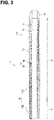
FIG. 3 is a cross-sectional view of a shaft portion and a distal tip. -
FIG. 4 is a cross-sectional view of a rotation transmission structure. -
FIG. 5 is an exploded perspective view of a rotation transmission structure. -
FIG. 6 is a cross-sectional view taken along line A-A inFIG. 4 . -
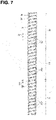
FIG. 7 is a cross-sectional view of a rotation transmission structure according to a second embodiment. -
FIG. 8 is an exploded perspective view of a rotation transmission structure. -
FIG. 9 is a cross-sectional view of a rotation transmission structure according to a third embodiment. -
FIG. 10 is an exploded perspective view of a rotation transmission structure. -
FIG. 11 is a cross-sectional view of a rotation transmission structure according to a fourth embodiment. -
FIG. 12 is an exploded perspective view of a rotation transmission structure. -
FIG. 13 is an overall view of a guide wire according to a fifth embodiment. -
FIG. 14 is a perspective view showing a reinforcing body according to another embodiment. - The following is a description of a preferred embodiment of the present invention.
- The reinforcing body may be configured by a plurality of connection portions provided in each section that connects the wires to one another, and the plurality of connection portions may be arranged more sparsely in the predetermined region than in the another region. According to this configuration, the rigidity of the rotation transmission structure can be suitably adjusted by changing the arrangement of the plurality of connection portions.
- The plurality of connection portions may be arranged along a virtual helical shape, and a pitch of the helical shape in the predetermined region may be larger than a pitch of the helical shape in the another region. According to this configuration, the rigidity of the rotation transmission structure can be suitably adjusted by changing the pitch of the helical shape.
- The reinforcing body may be configured by a plurality of connection portions provided in each section that connects the wires to one another, and a Young's modulus of a material of the connection portions arranged in the predetermined region may be smaller than a Young's modulus of a material of the connection portions arranged in the another region. According to this configuration, the rigidity of the rotation transmission structure can be suitably adjusted by changing the Young's modulus of the material of the connection portions.
- The reinforcing body may be configured by a plurality of connection portions provided in each section that connects the wires to one another, and the plurality of connection portions may be arranged along a virtual helical shape in an opposite direction to a winding direction of the coil body. According to this configuration, the rotation transmission properties are better than that in a configuration where the plurality of connection portions are arranged along a virtual helical shape in the same direction as the winding direction of the coil body.
- The reinforcing body may be configured by a plurality of connection portions provided in each section that connects the wires to one another, and the plurality of connection portions may be arranged along multiple virtual helical shapes. According to this configuration, the range over which the rigidity can be adjusted by the reinforcing body can be made larger than that in a configuration where the plurality of connection portions are arranged along a single helical shape.
- An outer diameter of the reinforcing body may be less than or equal to a maximum outer diameter of the coil body. According to this configuration, the outer diameter of the rotation transmission structure can be prevented from becoming larger as a result of providing the reinforcing body.
- An inner diameter of the reinforcing body may be greater than or equal to a minimum inner diameter of the coil body. According to this configuration, the inner diameter of the rotation transmission structure can be prevented from becoming smaller as a result of providing the reinforcing body.
- A catheter of the present invention includes a shaft portion reinforced by the rotation transmission structure described above, and the predetermined region of the rotation transmission structure may be located on a distal end side of the another region. According to this configuration, it is possible to realize a catheter having excellent rotation transmission properties, and which also ensures flexibility of the distal end portion.
- A guide wire of the present invention includes the rotation transmission structure described above and a core shaft inserted through a lumen of the rotation transmission structure, and the predetermined region of the rotation transmission structure may be located on a distal end side of the another region. According to this configuration, it is possible to realize a guide wire having excellent rotation transmission properties, and which also ensures flexibility of the distal end portion.
- Next, a first embodiment that embodies the present invention will be described with reference to
FIG. 1 to FIG. 6 . InFIG. 1 , the right side of the drawing is the distal end side (farther side) inserted into the body, and the left side is the rear end side (near side, proximal end side) operated by an operator such as a physician. -
FIG. 1 is an explanatory diagram showing a medical catheter (a type of medical device) 10 provided with arotation transmission structure 20. Thecatheter 10 includes ashaft portion 11, adistal tip 12 provided on the distal end side of theshaft portion 11, and aconnector 13 provided on the proximal end side of theshaft portion 11. The rigidity of thedistal end portion 11A of theshaft portion 11 is lower than the rigidity of the section other than thedistal end portion 11A. The section of theshaft portion 11 other than thedistal end portion 11A is a section also referred to as a body portion or a proximal end portion of theshaft portion 11. - As shown in
FIG. 2 , theshaft portion 11 includes, in order from the inside, aninner layer 14, arotation transmission structure 20 serving as a reinforcing body, amiddle layer 15, and anouter layer 16. - The
inner layer 14 is made of resin and constitutes alumen 17 for inserting a guide wire or another catheter inside. The resin material forming theinner layer 14 is not particularly limited, but in the present embodiment, PTFE (polytetrafluoroethylene) is used. Therotation transmission structure 20 serving as the reinforcing body is formed on the outer periphery of theinner layer 14. The configuration of therotation transmission structure 20 will be described later. - The
middle layer 15 made of resin is formed on the outer periphery of therotation transmission structure 20, and covers theinner layer 14 and therotation transmission structure 20. The resin material used to form themiddle layer 15 is not particularly limited, and polyamide, polyamide elastomer, polyester, polyurethane or the like are used. - As shown in the cross-sectional view in
FIG. 3 , themiddle layer 15 covers theshaft portion 11 except for thedistal tip 12. Themiddle layer 15 is bonded to theinner layer 14 in the gaps of the rotation transmission structure 20 (in other words, thegaps 32 between adjacent wires 31). - The
outer layer 16 made of resin is formed on the outer periphery of themiddle layer 15, and covers themiddle layer 15. Like themiddle layer 15, the resin material used to form theouter layer 16 is not particularly limited, and polyamide, polyamide elastomer, polyester, polyurethane or the like is used. Theouter layer 16 may be made using resin materials having different hardnesses so as to become more flexible toward thedistal end portion 11A side of theshaft portion 11. For example, a firstouter layer 16A covering thedistal end portion 11A may be made of a more flexible resin than a secondouter layer 16B that covers the section other than thedistal end portion 11A. - As shown in
FIG. 4 , therotation transmission structure 20 includes acoil body 30 and a reinforcingbody 40. Therotation transmission structure 20 has afirst region 21, and asecond region 22 located on the proximal end side of thefirst region 21. Thefirst region 21 corresponds to a predetermined region in the longitudinal direction. Thesecond region 22 corresponds to another region. Specifically, thefirst region 21 constitutes thedistal end portion 11A of theshaft portion 11. Thesecond region 22 constitutes the section of theshaft portion 11 other than thedistal end portion 11A. - As shown in
FIG. 4 andFIG. 5 , thecoil body 30 is formed by windingwires 31. Thewires 31 are flattened wires. The cross-sectional shape of the wires may be substantially rectangular, or may be substantially circular or polygonal. The diameter of thewires 31 is substantially constant over the entire length. The material of thewires 31 is not particularly limited, but is preferably a biocompatible material that is resistant to corrosion, such as stainless steel alloy (SUS), nickel titanium alloy (NiTi), titanium (Ti), platinum (Pt), tungsten (W), gold (Au), and silver (Ag). - The
coil body 30 is wound in a helical shape. The outer diameter and the inner diameter of thecoil body 30 is substantially constant over the entire length. When thecoil body 30 is not connected by the reinforcingbody 40, the flexural rigidity and torsional rigidity are substantially constant over the entire length. Thecoil body 30 adopts a so-called coarse winding, in which theadjacent wires 31 are not in contact with one another. In other words, thecoil body 30 hasgaps 32 that are formed between theadjacent wires 31. - The reinforcing
body 40 is a member that connects theadjacent wires 31 of thecoil body 30 to one another. The material of the reinforcingbody 40 is not particularly limited, and may be the same material as thecoil body 30 or may be a different material. Examples of the material of the reinforcingbody 40 include metal materials such as stainless steel (SUS), nickel-titanium alloy (NiTi), titanium (Ti), and nickel-chromium alloy (NiCr), metal brazing materials, and resin-based adhesives. Furthermore, the reinforcingbody 40 may be formed of a portion of the material constituting thecoil body 30 by welding thewires 31 to one another. In the present embodiment, all areas of the reinforcingbody 40 are formed of the same material. - The reinforcing
body 40 is provided such that, when thewires 31 of thecoil body 30 are connected to one another, the rigidity of thefirst region 21 is lower than the rigidity of thesecond region 22. The reinforcingbody 40 is provided in both thefirst region 21 and thesecond region 22. The rigidity of thefirst region 21 is higher than the rigidity of thecoil body 30 which is not connected by the reinforcingbody 40, and lower than the rigidity of thesecond region 22. The rigidity of therotation transmission structure 20 gradually decreases from thesecond region 22 toward thefirst region 21. Flexural rigidity and torsional rigidity are examples of rigidity indexes. - The reinforcing
body 40 is configured by a plurality ofconnection portions wires 31 to one another. Among the plurality ofconnection portions connection portions 41 are arranged in thefirst region 21, and the plurality ofconnection portions 42 are arranged in thesecond region 22. - The plurality of
connection portions first region 21 than in thesecond region 22. In other words, the density of the plurality ofconnection portions 41 is smaller than the density of the plurality ofconnection portions 42. The density of the plurality ofconnection portions 41 can be calculated, for example, as the mass of the plurality ofconnection portions 41 per unit length of thecoil body 30. Here, the unit length of thecoil body 30 may be appropriately set according to the distribution of the plurality ofconnection portions connection portions 42 can be calculated in the same manner as the density of the plurality ofconnection portions 41. The density of the plurality ofconnection portions - The plurality of
connection portions coil body 30, and for example, when thecoil body 30 is wound in an anticlockwise direction toward the distal end (S-twisted), the plurality ofconnection portions - The pitch P1 of the helical shape S1 in the
first region 21 is larger than the pitch P2 of the helical shape S1 in thesecond region 22. In other words, therotation transmission structure 20 has a configuration in which the pitch of the helical shape S1 is variable in order to adjust the rigidity. The pitch of thehelical shape S 1 is the dimension between the windings of the helical shape S1 in the length direction of therotation transmission structure 20. The pitch P1 of the helical shape S1 in thefirst region 21 becomes gradually larger toward the distal end side. - The size of the
connection portions 41 is smaller than the size of theconnection portions 42. Specifically, in the winding direction of thewires 31, the dimensions of theconnection portions 41 are smaller than the dimensions of theconnection portions 42. The size of the plurality ofconnection portions - As shown in
FIG. 6 , the outer diameter of the reinforcingbody 40 is less than or equal to the maximum outer diameter of thecoil body 30. In other words, the reinforcingbody 40 is arranged on the inner peripheral side of a virtualcylindrical surface 34A circumscribed around the outerperipheral surface 34 of thecoil body 30. Furthermore, the inner diameter of the reinforcingbody 40 is greater than or equal to the minimum inner diameter of thecoil body 30. In other words, the reinforcingbody 40 is arranged on the outer peripheral side of a virtualcylindrical surface 35A inscribed in the innerperipheral surface 35 of thecoil body 30. That is, the reinforcingbody 40 takes a form in which the plurality ofconnection portions gaps 32 betweenwires 31 that are adjacent to each other. The outer surface of the reinforcingbody 40 is flush with the outerperipheral surface 34 of thecoil body 30. The inner surface of the reinforcingbody 40 is flush with the innerperipheral surface 35 of thecoil body 30. The size and arrangement of the reinforcingbody 40 are not limited to this. For example, in the radial direction of thecoil body 30, a configuration is possible in which the dimensions of the reinforcing body 40 (connection portions 41 and 42) are smaller than the thickness dimension of thewires 31, and theconnection portions peripheral surface 34 and the innerperipheral surface 35. - Next, the effects of the present embodiment will be described.
- According to the
rotation transmission structure 20 of the present embodiment, the rotation transmission properties of therotation transmission structure 20 can be improved compared to a coil body that is not connected by the reinforcingbody 40, and the rigidity of therotation transmission structure 20 can also be adjusted by the reinforcingbody 40. For example, according to therotation transmission structure 20, it is possible to improve the operability of thecatheter 10 by increasing the rigidity of the section of theshaft portion 11 other than thedistal end portion 11A, while also ensuring the flexibility of therotation transmission structure 20 with thedistal end portion 11A of theshaft portion 11. - In order to confirm the effects of the present embodiment, the flexural rigidity of the rotation transmission structure was calculated by simulation with the pitch of the helical shape of the reinforcing body changed. From this result, it was confirmed that the flexural rigidity decreases when the pitch of the helical shape of the reinforcing body is increased. Furthermore, the torsional rigidity of the rotation transmission structure was calculated by simulation with the pitch of the helical shape of the reinforcing body changed. From this result, it was confirmed that the torsional rigidity decreases when the pitch of the helical shape of the reinforcing body is increased. In addition, it was confirmed that when the pitch is increased in steps, the flexural rigidity tends to be smaller than the torsional rigidity under predetermined conditions. This result suggested that, for example, by reducing the flexural rigidity while maintaining the torsional rigidity corresponding to the parts of the
rotation transmission structure 20, or the like, a flexural rigidity and torsional rigidity corresponding to a medical device to which therotation transmission structure 20 has been applied can be realized by the reinforcingbody 40. - Furthermore, in a configuration where a slot pattern is formed on the side surface of the tubular member in order to adjust the rigidity of the rotation transmission structure, when a rotational force is applied to the rotation transmission structure, stress is concentrated on the opening edge of the slot formed in the tubular member, and there is a concern that the rotation transmission structure may break or the like. In contrast, in the present embodiment, when a rotational force is applied to the
rotation transmission structure 20, even if some of the connections between thewires 31 of thecoil body 30 become detached, thecoil body 30 itself can be prevented from breaking. - In the present embodiment, the plurality of
connection portions first region 21 than in thesecond region 22. This enables the rigidity of therotation transmission structure 20 to be suitably adjusted by changing the arrangement of the plurality ofconnection portions - In the present embodiment, the pitch P1 of the helical shape S1 in the
first region 21 is larger than the pitch P2 of the helical shape S1 in thesecond region 22. This enables the rigidity of therotation transmission structure 20 to be suitably adjusted by changing the pitches P1 and P2 of the helical shape S1. - In the present embodiment, the plurality of
connection portions coil body 30. Consequently, the rotation transmission properties are better than those in a configuration where the plurality ofconnection portions coil body 30. - In the present embodiment, the outer diameter of the reinforcing
body 40 is less than or equal to the maximum outer diameter of thecoil body 30. This prevents the outer diameter of therotation transmission structure 20 from becoming larger as a result of providing the reinforcingbody 40. The inner diameter of the reinforcingbody 40 is greater than or equal to the minimum inner diameter of thecoil body 30. This prevents the inner diameter of therotation transmission structure 20 from becoming smaller as a result of providing the reinforcingbody 40. Further, in the present embodiment, the reinforcingbody 40 is arranged in thegaps 32 between thewires 31. As a result, when therotation transmission structure 20 is pushed in, the pushing force can be more easily transmitted to the distal end side, and the pushability of therotation transmission structure 20 can be improved. - The
catheter 10 of the present embodiment includes theshaft portion 11 reinforced by therotation transmission structure 20 described above, and thefirst region 21 of therotation transmission structure 20 is located on the distal end side of thesecond region 22. This makes it possible to realize thecatheter 10 having excellent rotation transmission properties, and which ensures flexibility of thedistal end portion 11A. - As shown in
FIG. 7 andFIG. 8 , therotation transmission structure 220 according to the second embodiment has a reinforcing body with a different configuration to that of the first embodiment. Configurations that are identical to those in the first embodiment are designated by the same reference numerals, and duplicate description will be omitted. - The
rotation transmission structure 220 includes acoil body 30 and a reinforcingbody 240. Therotation transmission structure 220 has afirst region 21, and asecond region 22 located on the proximal end side of thefirst region 21, and anintermediate region 23 located between thefirst region 21 and thesecond region 22. Thefirst region 21 corresponds to a predetermined region in the longitudinal direction. Thesecond region 22 corresponds to another region. Specifically, thefirst region 21 constitutes thedistal end portion 11A of theshaft portion 11. Thesecond region 22 constitutes the proximal end portion of theshaft portion 11. - The reinforcing
body 240 is provided such that, when thewires 31 of thecoil body 30 are connected to one another, the rigidity of thefirst region 21 is lower than the rigidity of thesecond region 22. The reinforcingbody 240 is provided in thefirst region 21, thesecond region 22, and theintermediate region 23. The rigidity of thefirst region 21 is higher than the rigidity of thecoil body 30 which is not provided with the reinforcingbody 240, and lower than the rigidity of thesecond region 22 and theintermediate region 23. The rigidity of theintermediate region 23 is lower than the rigidity of thesecond region 22. The rigidity of therotation transmission structure 220 decreases in multiple steps from thesecond region 22 toward thefirst region 21. Flexural rigidity and torsional rigidity are examples of rigidity indexes. - The reinforcing
body 240 is configured by a plurality ofconnection portions wires 31 to one another. Among the plurality ofconnection portions connection portions 241 are arranged in thefirst region 21, and the plurality ofconnection portions 242 are arranged in thesecond region 22. The plurality ofconnection portions 243 are arranged in theintermediate region 23. The plurality ofconnection portions 241 correspond to the connection portions arranged in the predetermined region. The plurality ofconnection portions 242 correspond to the connection portions arranged in the another region. - The plurality of
connection portions coil body 30, and for example, when thecoil body 30 is wound in an anticlockwise direction toward the distal end (S-twisted), the plurality ofconnection portions connection portions 241 is the same as the density of the plurality ofconnection portions 242. - The Young's modulus of the material forming the
connection portions 241 is smaller than the Young's modulus of the material forming theconnection portions 242. Specifically, the plurality ofconnection portions 241 are made of the same first material. InFIG. 8 , the connection portions formed of the first material are shown in black. The plurality ofconnection portions 242 are made of the same second material. InFIG. 8 , the connection portions formed of the second material are shown in white. The Young's modulus of this first material is smaller than the Young's modulus of the second material. Among the plurality ofconnection portions 243, half of theconnection portions 243 are composed of the first material, and the remaining half of theconnection portions 243 among the plurality ofconnection portions 243 are composed of the second material. Of the four helical shapes S1 to S4, the plurality ofconnection portions 243 composed of the first material are arranged along the two helical shapes S1 and S3. Of the four helical shapes S1 to S4, the plurality ofconnection portions 243 composed of the second material are arranged along the two helical shapes S2 and S4. - Next, the effects of the present embodiment will be described.
- According to the
rotation transmission structure 220 of the present embodiment, the rotation transmission properties can be improved compared to a coil body that is not connected by the reinforcingbody 240, and the rigidity of therotation transmission structure 220 can also be adjusted by the reinforcingbody 240. For example, according to therotation transmission structure 220, it is possible to improve the operability of thecatheter 10 by increasing the rigidity of the section of theshaft portion 11 other than thedistal end portion 11A, while also ensuring the flexibility of therotation transmission structure 220 in thedistal end portion 11A of theshaft portion 11. - In order to confirm the effects of the present embodiment, the flexural rigidity of the rotation transmission structure was calculated by simulation with the Young's modulus of the material forming the plurality of connection portions changed. From this result, it was confirmed that the flexural rigidity decreases when the Young's modulus of the material forming the plurality of connection portions is decreased. Furthermore, the torsional rigidity of the rotation transmission structure was calculated by simulation with the Young's modulus of the material forming the plurality of connection portions changed. From this result, it was confirmed that the torsional rigidity decreases when the Young's modulus of the material forming the plurality of connection portions is decreased. In addition, it was confirmed that when the Young's modulus of the material forming the reinforcing body is decreased in steps, the flexural rigidity tends to be smaller than the torsional rigidity under predetermined conditions. This result suggested that, for example, by reducing the flexural rigidity while maintaining the torsional rigidity corresponding to the parts of the
rotation transmission structure 220, or the like, a flexural rigidity and torsional rigidity corresponding to a medical device to which therotation transmission structure 220 has been applied can be realized by the reinforcingbody 240. - The Young's modulus of the material of the
connection portions 241 arranged in thefirst region 21 is smaller than the Young's modulus of the material of theconnection portions 242 arranged in thesecond region 22. This enables the rigidity of therotation transmission structure 220 to be suitably adjusted by changing the Young's modulus of the material of theconnection portions - The plurality of
connection portions connection portions 241 and the plurality ofconnection portions 242 to be made larger than that in a configuration where the plurality ofconnection portions - In the present embodiment, because the plurality of
connection portions 243 composed of a material having a different Young's modulus are arranged in theintermediate region 23, the rigidity of therotation transmission structure 220 can be gradually changed. - As shown in
FIG. 9 andFIG. 10 , therotation transmission structure 320 according to the third embodiment has a reinforcing body with a different configuration to that of the first embodiment. Configurations that are identical to those in the first embodiment are designated by the same reference numerals, and duplicate description will be omitted. - The reinforcing
body 340 is configured by a plurality ofconnection portions wires 31 to one another. Among the plurality ofconnection portions connection portions 341 are arranged in thefirst region 21, and the plurality ofconnection portions 342 are arranged in thesecond region 22. The plurality ofconnection portions coil body 30, and for example, when thecoil body 30 is wound in an anticlockwise direction toward the distal end (S-twisted), the plurality ofconnection portions - The plurality of
connection portions first region 21 than in thesecond region 22. In other words, the density of the plurality ofconnection portions 341 is smaller than the density of the plurality ofconnection portions 342. The density of the plurality ofconnection portions 341 can be calculated, for example, as the mass of the plurality ofconnection portions 341 per unit length of thecoil body 30. The density of the plurality ofconnection portions 342 can be calculated in the same manner. Here, the unit length of thecoil body 30 may be appropriately set according to the distribution of the plurality ofconnection portions - The pitch P1 of the helical shape S1 in the
first region 21 is larger than the pitch P2 of the helical shape S1 in thesecond region 22. The pitch of the helical shape S1 is the dimension between the windings of the helical shape S1 in the length direction of therotation transmission structure 320. The pitch P1 of the helical shape S1 in thefirst region 21 is the same in all areas, and the pitch P2 of the helical shape S1 in thesecond region 22 is the same in all areas. In other words, the pitch of the helical shape S1 increases in steps toward the distal end side. - In the present embodiment, the rigidity of the
rotation transmission structure 320 can be suitably adjusted by a simple configuration in which pitch of the helical shape is changed in steps. The rigidity of therotation transmission structure 320 decreases in steps from thesecond region 22 toward thefirst region 21. - As shown in
FIG. 11 andFIG. 12 , therotation transmission structure 420 according to the fourth embodiment has a reinforcing body with a different configuration to that of the first embodiment. Configurations that are identical to those in the first embodiment are designated by the same reference numerals, and duplicate description will be omitted. - The reinforcing
body 440 is configured by a plurality ofconnection portions wires 31 to one another. Among the plurality ofconnection portions connection portions 441 are arranged in thefirst region 21, and the plurality ofconnection portions 442 are arranged in thesecond region 22. The plurality ofconnection portions 441 are arranged along a single virtual helical shape S1. The plurality ofconnection portions 442 are arranged along two virtual helical shapes S1 and S2. The helical shapes S1 and S2 are in the opposite direction to the winding direction of thecoil body 30, and for example, when thecoil body 30 is wound in an anticlockwise direction toward the distal end (S-twisted), the plurality ofconnection portions - In the present embodiment, the rigidity of the
rotation transmission structure 420 can be suitably adjusted by a simple configuration in which the number of helical shapes S1 and S2 is changed. The rigidity of therotation transmission structure 420 decreases in steps from thesecond region 22 toward thefirst region 21. - The
rotation transmission structure 520 according to the fifth embodiment is different to that of the first embodiment in that it constitutes aguide wire 510. Configurations that are identical to those in the first embodiment are designated by the same reference numerals, and duplicate description will be omitted. -
FIG. 13 is an explanatory diagram showing a guide wire (a type of medical device) 510 provided with therotation transmission structure 520. Theguide wire 510 includes therotation transmission structure 520, acore shaft 511 inserted through the lumen of therotation transmission structure 520, and the like. The distal end of therotation transmission structure 520 and the distal end of thecore shaft 511 are connected by a distal end brazedportion 512, and the proximal end of therotation transmission structure 520 and the intermediate portion of thecore shaft 511 are connected by a proximal end brazedportion 513. - The
rotation transmission structure 520 includes acoil body 30 and a reinforcingbody 40. Therotation transmission structure 520 has afirst region 21, and asecond region 22 located on the proximal end side of thefirst region 21. Thefirst region 21 corresponds to a predetermined region in the longitudinal direction. Thesecond region 22 corresponds to another region. The configuration of therotation transmission structure 520 is the same as that of the first embodiment, and the description thereof will be omitted. - In the
guide wire 510 of the present embodiment, thefirst region 21 of therotation transmission structure 520 is located on the distal end side of thesecond region 22. As a result, it is possible to realize aguide wire 510 having excellent rotation transmission properties and which ensures flexibility of the distal end portion. - The present invention are not limited to the examples described in the above description and drawings, and for example, the following examples are also included in the technical scope of the present invention.
- (1) In addition to the embodiments above, the positions and ranges of the first region and the second region of the rotation transmission structure can be appropriately changed. For example, the first region is not limited to being the distal end portion of the shaft portion, and may constitute any region of the shaft portion that requires flexibility. The second region is not limited to being on the proximal end side of the first region, and may be located on the distal end side. The second region is not limited to being the entire region other than the first region, and may constitute a partial region. Further, in addition to the intermediate region, the rotation transmission structure may have a third region having a different rigidity from those in both the first region and the second region.
- (2) The configuration in which the rigidity of the rotation transmission structure is changed by the reinforcing body is not limited to the configurations of the embodiments above. For example, the rigidity of the rotation transmission structure can be changed by combining changes in one or more of the size of the reinforcing body, the physical properties of the material forming the reinforcing body, the pitch of the helical shape, and the number of the helical shapes.
- (3) The reinforcing body is not limited to being configured by a plurality of connection portions, and may be configured by a single member. In such a case, as shown in
FIG. 14 , the reinforcingbody 640 may be formed with a longitudinal shape with a smaller width dimension toward the distal end side, and sections in which the width dimension of the reinforcingbody 640 are different may be provided in thefirst region 21 and thesecond region 22. Furthermore, the reinforcingbody 640 configured by such a single member may be provided on the outside of thecoil body 30 as shown inFIG. 14 , or may be provided on the inside of the coil body. - (4) The plurality of connection portions may be arranged along a virtual helical shape in the same direction as the winding direction of the coil body. The plurality of connection portions do not have to be arranged along a virtual helical shape, and for example, may be arranged along the longitudinal direction of the coil body.
- (5) In addition to the above embodiments, the configuration of the coil body can be changed. For example, the coil body may have regions having different rigidities when not connected by the reinforcing body. It is also possible for the coil body to be densely wound such that it does not have gaps between the wires. The winding direction of the coil body is not limited.
- (6) The above embodiments illustrated configurations in which the diameter of the wires is substantially constant over the entire length, however the diameter of the wires may also become thinner from the proximal end toward the distal end.
- (7) The manner in which the rigidity of the rotation transmission structure changes is not limited to the configurations of the above embodiments. The rigidity of the rotation transmission structure may change gradually, or may change in steps with an arbitrary number of steps.
- (8) The rotation transmission structure may be provided in a medical device other than a catheter, such as a guide wire. The rotation transmission structure may be coated with a resin layer or the like depending on the medical device in which it is used.
-
- 10 Catheter
- 11 Shaft portion
- 11A Distal end portion
- 12 Distal tip
- 13 Connector
- 20, 220, 320, 420, 520 Rotation transmission structure
- 21 First region (predetermined region)
- 22 Another region (second region)
- 23 Intermediate region
- 30 Coil body
- 31 Wire
- 32 Gap
- 34 Outer peripheral surface
- 34A Virtual cylindrical surface
- 35 Inner peripheral surface
- 35A Virtual cylindrical surface
- 40, 240, 340, 440, 640 Reinforcing body
- 41, 241, 341, 441 Connection portion (connection portion arranged in predetermined region)
- 42, 242, 342, 442 Connection portion (connection portion arranged in another region)
- 243 Connection portion
- 510 Guide wire
- 511 Core shaft
- S1, S2, S3, S4 Helical shape
Claims (10)
- A rotation transmission structure comprising: a coil body formed by winding wires; and a reinforcing body that connects adjacent wires of the coil body; wherein the reinforcing body is provided such that, when the wires of the coil body are connected to one another, rigidity of a predetermined region in a longitudinal direction is lower than rigidity of another region.
- The rotation transmission structure according to claim 1, wherein the reinforcing body is configured by a plurality of connection portions provided in each section that connects the wires to one another, and the plurality of connection portions are arranged more sparsely in the predetermined region than in the another region.
- The rotation transmission structure according to claim 2, wherein the plurality of connection portions are arranged along a virtual helical shape, and a pitch of the helical shape in the predetermined region is larger than a pitch of the helical shape in the another region.
- A rotation transmission structure according to any one of claims 1 to 3, wherein the reinforcing body is configured by a plurality of connection portions provided in each section that connects the wires to one another, and a Young's modulus of a material of the connection portions arranged in the predetermined region is smaller than a Young's modulus of a material of the connection portions arranged in the another region.
- A rotation transmission structure according to any one of claims 1 to 4, wherein the reinforcing body is configured by a plurality of connection portions provided in each section that connects the wires to one another, and the plurality of connection portions are arranged along a virtual helical shape in an opposite direction to a winding direction of the coil body.
- A rotation transmission structure according to any one of claims 1 to 5, wherein the reinforcing body is configured by a plurality of connection portions provided in each section that connects the wires to one another, and the plurality of connection portions are arranged along multiple virtual helical shapes.
- A rotation transmission structure according to any one of claims 1 to 6, wherein an outer diameter of the reinforcing body is less than or equal to a maximum outer diameter of the coil body.
- A rotation transmission structure according to any one of claims 1 to 7, wherein an inner diameter of the reinforcing body is greater than or equal to a minimum inner diameter of the coil body.
- A catheter comprising a shaft portion reinforced by the rotation transmission structure according to any one of claims 1 to 8, wherein the predetermined region of the rotation transmission structure is located on a distal end side of the another region.
- A guide wire comprising: the rotation transmission structure according to any one of claims 1 to 8; and a core shaft inserted through a lumen of the rotation transmission structure; wherein the predetermined region of the rotation transmission structure is located on a distal end side of the another region.
Applications Claiming Priority (1)
| Application Number | Priority Date | Filing Date | Title |
|---|---|---|---|
| PCT/JP2020/003621 WO2021152816A1 (en) | 2020-01-31 | 2020-01-31 | Rotation transmission structure, catheter, and guide wire |
Publications (3)
| Publication Number | Publication Date |
|---|---|
| EP4098308A1 true EP4098308A1 (en) | 2022-12-07 |
| EP4098308A4 EP4098308A4 (en) | 2023-11-29 |
| EP4098308B1 EP4098308B1 (en) | 2026-04-08 |
Family
ID=77078763
Family Applications (1)
| Application Number | Title | Priority Date | Filing Date |
|---|---|---|---|
| EP20916281.7A Active EP4098308B1 (en) | 2020-01-31 | 2020-01-31 | Rotation transmission structure, catheter, and guide wire |
Country Status (5)
| Country | Link |
|---|---|
| US (1) | US12496430B2 (en) |
| EP (1) | EP4098308B1 (en) |
| JP (3) | JP7314321B2 (en) |
| CN (1) | CN114929320A (en) |
| WO (1) | WO2021152816A1 (en) |
Family Cites Families (15)
| Publication number | Priority date | Publication date | Assignee | Title |
|---|---|---|---|---|
| US7833175B2 (en) * | 2003-09-05 | 2010-11-16 | Boston Scientific Scimed, Inc. | Medical device coil |
| WO2005118045A1 (en) * | 2004-05-27 | 2005-12-15 | Abbott Laboratories | Catheter having main body portion with coil-defined guidewire passage |
| CA2630215A1 (en) * | 2005-11-17 | 2007-05-24 | Micromuscle Ab | Medical devices and methods for their fabrication and use |
| JP2009125774A (en) | 2007-11-22 | 2009-06-11 | Tokuriki Honten Co Ltd | Micro thin metal pipe and manufacturing method thereof |
| US8157751B2 (en) * | 2007-12-13 | 2012-04-17 | Boston Scientific Scimed, Inc. | Coil member for a medical device |
| EP2234663A1 (en) * | 2007-12-19 | 2010-10-06 | Boston Scientific Scimed, Inc. | Structure for use as part of a medical device |
| JP5742238B2 (en) * | 2011-01-19 | 2015-07-01 | 住友ベークライト株式会社 | Medical equipment |
| JP2015036090A (en) * | 2013-08-15 | 2015-02-23 | 朝日インテック株式会社 | Coil body and guide wire using the coil body |
| JP2015159865A (en) * | 2014-02-26 | 2015-09-07 | 朝日インテック株式会社 | Guide wire |
| CN107666935B (en) * | 2015-05-29 | 2021-01-05 | 柯惠有限合伙公司 | Catheter with tapered outer diameter |
| KR102457315B1 (en) * | 2016-08-17 | 2022-10-24 | 뉴라비 리미티드 | A thrombus recovery system to remove an occlusive thrombus from a blood vessel |
| US10821268B2 (en) | 2016-09-14 | 2020-11-03 | Scientia Vascular, Llc | Integrated coil vascular devices |
| US11452541B2 (en) * | 2016-12-22 | 2022-09-27 | Scientia Vascular, Inc. | Intravascular device having a selectively deflectable tip |
| EP4257173A3 (en) | 2017-05-26 | 2023-11-29 | Scientia Vascular, Inc. | Micro-fabricated medical device having a non-helical cut arrangement |
| US20210093619A1 (en) | 2017-06-07 | 2021-04-01 | Glaxosmithkline Intellectual Property Development Limited | Chemical Compounds as ATF-4 Pathway Inhibitors |
-
2020
- 2020-01-31 WO PCT/JP2020/003621 patent/WO2021152816A1/en not_active Ceased
- 2020-01-31 JP JP2021574402A patent/JP7314321B2/en active Active
- 2020-01-31 EP EP20916281.7A patent/EP4098308B1/en active Active
- 2020-01-31 CN CN202080092494.4A patent/CN114929320A/en active Pending
-
2022
- 2022-07-20 US US17/869,201 patent/US12496430B2/en active Active
-
2023
- 2023-07-12 JP JP2023114185A patent/JP7566090B2/en active Active
-
2024
- 2024-10-01 JP JP2024171917A patent/JP7690667B2/en active Active
Also Published As
| Publication number | Publication date |
|---|---|
| US20220347427A1 (en) | 2022-11-03 |
| JP7690667B2 (en) | 2025-06-10 |
| JP7314321B2 (en) | 2023-07-25 |
| EP4098308B1 (en) | 2026-04-08 |
| JPWO2021152816A1 (en) | 2021-08-05 |
| CN114929320A (en) | 2022-08-19 |
| WO2021152816A1 (en) | 2021-08-05 |
| JP7566090B2 (en) | 2024-10-11 |
| JP2024174116A (en) | 2024-12-13 |
| US12496430B2 (en) | 2025-12-16 |
| EP4098308A4 (en) | 2023-11-29 |
| JP2023129469A (en) | 2023-09-14 |
Similar Documents
| Publication | Publication Date | Title |
|---|---|---|
| US5826576A (en) | Electrophysiology catheter with multifunction wire and method for making | |
| JP2017205524A (en) | Steerable delivery sheath | |
| US20090177040A1 (en) | Instrument shaft | |
| CN104739375A (en) | Catheter | |
| CN110545874A (en) | Twistable steerable sheath | |
| WO1993008869A1 (en) | Catheter with electrode tip having asymmetric configurations | |
| EP4233971B1 (en) | Guidewires for medical devices | |
| CN116685257A (en) | Steerable catheter design with spine-reinforced molded articulating joint | |
| US20150238735A1 (en) | Guide wire | |
| CN107802942B (en) | Medical guide wire | |
| JPH0147171B2 (en) | ||
| JP7050175B2 (en) | Medical equipment | |
| WO2022074960A1 (en) | Guide wire | |
| EP4098308B1 (en) | Rotation transmission structure, catheter, and guide wire | |
| JP7651570B2 (en) | catheter | |
| CN115734797B (en) | catheter | |
| JP7555185B2 (en) | catheter | |
| JP7588212B2 (en) | Electrode Catheter | |
| US20250090001A1 (en) | Endoscope with insertion tube having adjacent cuts with unequal spacing and method of manufacturing such an endoscope | |
| US20240390640A1 (en) | Braided structure, tube structure, tube structure for catheter, method for manufacturing braided structure | |
| CN119546362A (en) | Guidewire | |
| HK40083950B (en) | Guidewire devices having shapeable polymer tips | |
| WO2025243997A1 (en) | Catheter | |
| WO2025205429A1 (en) | Catheter shaft and catheter |
Legal Events
| Date | Code | Title | Description |
|---|---|---|---|
| STAA | Information on the status of an ep patent application or granted ep patent |
Free format text: STATUS: THE INTERNATIONAL PUBLICATION HAS BEEN MADE |
|
| PUAI | Public reference made under article 153(3) epc to a published international application that has entered the european phase |
Free format text: ORIGINAL CODE: 0009012 |
|
| STAA | Information on the status of an ep patent application or granted ep patent |
Free format text: STATUS: REQUEST FOR EXAMINATION WAS MADE |
|
| 17P | Request for examination filed |
Effective date: 20220809 |
|
| AK | Designated contracting states |
Kind code of ref document: A1 Designated state(s): AL AT BE BG CH CY CZ DE DK EE ES FI FR GB GR HR HU IE IS IT LI LT LU LV MC MK MT NL NO PL PT RO RS SE SI SK SM TR |
|
| DAV | Request for validation of the european patent (deleted) | ||
| DAX | Request for extension of the european patent (deleted) | ||
| A4 | Supplementary search report drawn up and despatched |
Effective date: 20231030 |
|
| RIC1 | Information provided on ipc code assigned before grant |
Ipc: A61M 25/00 20060101AFI20231024BHEP |
|
| GRAP | Despatch of communication of intention to grant a patent |
Free format text: ORIGINAL CODE: EPIDOSNIGR1 |
|
| STAA | Information on the status of an ep patent application or granted ep patent |
Free format text: STATUS: GRANT OF PATENT IS INTENDED |
|
| INTG | Intention to grant announced |
Effective date: 20251111 |
|
| GRAS | Grant fee paid |
Free format text: ORIGINAL CODE: EPIDOSNIGR3 |
|
| GRAA | (expected) grant |
Free format text: ORIGINAL CODE: 0009210 |
|
| STAA | Information on the status of an ep patent application or granted ep patent |
Free format text: STATUS: THE PATENT HAS BEEN GRANTED |
|
| RAP3 | Party data changed (applicant data changed or rights of an application transferred) |
Owner name: ASAHI INTECC CO., LTD. |
|
| AK | Designated contracting states |
Kind code of ref document: B1 Designated state(s): AL AT BE BG CH CY CZ DE DK EE ES FI FR GB GR HR HU IE IS IT LI LT LU LV MC MK MT NL NO PL PT RO RS SE SI SK SM TR |
|
| REG | Reference to a national code |
Ref country code: CH Ref legal event code: F10 Free format text: ST27 STATUS EVENT CODE: U-0-0-F10-F00 (AS PROVIDED BY THE NATIONAL OFFICE) Effective date: 20260408 Ref country code: GB Ref legal event code: FG4D |
|
| REG | Reference to a national code |
Ref country code: DE Ref legal event code: R096 Ref document number: 602020070231 Country of ref document: DE |