EP4097950B1 - Method and system for including dynamic service areas in access & mobility restriction control - Google Patents
Method and system for including dynamic service areas in access & mobility restriction control Download PDFInfo
- Publication number
- EP4097950B1 EP4097950B1 EP20703707.8A EP20703707A EP4097950B1 EP 4097950 B1 EP4097950 B1 EP 4097950B1 EP 20703707 A EP20703707 A EP 20703707A EP 4097950 B1 EP4097950 B1 EP 4097950B1
- Authority
- EP
- European Patent Office
- Prior art keywords
- service area
- node
- service
- area
- amf
- Prior art date
- Legal status (The legal status is an assumption and is not a legal conclusion. Google has not performed a legal analysis and makes no representation as to the accuracy of the status listed.)
- Active
Links
Images



Classifications
-
- H—ELECTRICITY
- H04—ELECTRIC COMMUNICATION TECHNIQUE
- H04W—WIRELESS COMMUNICATION NETWORKS
- H04W48/00—Access restriction; Network selection; Access point selection
- H04W48/02—Access restriction performed under specific conditions
- H04W48/04—Access restriction performed under specific conditions based on user or terminal location or mobility data, e.g. moving direction, speed
-
- H—ELECTRICITY
- H04—ELECTRIC COMMUNICATION TECHNIQUE
- H04L—TRANSMISSION OF DIGITAL INFORMATION, e.g. TELEGRAPHIC COMMUNICATION
- H04L67/00—Network arrangements or protocols for supporting network services or applications
- H04L67/14—Session management
- H04L67/142—Managing session states for stateless protocols; Signalling session states; State transitions; Keeping-state mechanisms
-
- H—ELECTRICITY
- H04—ELECTRIC COMMUNICATION TECHNIQUE
- H04L—TRANSMISSION OF DIGITAL INFORMATION, e.g. TELEGRAPHIC COMMUNICATION
- H04L67/00—Network arrangements or protocols for supporting network services or applications
- H04L67/2866—Architectures; Arrangements
- H04L67/30—Profiles
-
- H—ELECTRICITY
- H04—ELECTRIC COMMUNICATION TECHNIQUE
- H04L—TRANSMISSION OF DIGITAL INFORMATION, e.g. TELEGRAPHIC COMMUNICATION
- H04L67/00—Network arrangements or protocols for supporting network services or applications
- H04L67/50—Network services
- H04L67/535—Tracking the activity of the user
-
- H—ELECTRICITY
- H04—ELECTRIC COMMUNICATION TECHNIQUE
- H04W—WIRELESS COMMUNICATION NETWORKS
- H04W12/00—Security arrangements; Authentication; Protecting privacy or anonymity
- H04W12/80—Arrangements enabling lawful interception [LI]
-
- H—ELECTRICITY
- H04—ELECTRIC COMMUNICATION TECHNIQUE
- H04W—WIRELESS COMMUNICATION NETWORKS
- H04W4/00—Services specially adapted for wireless communication networks; Facilities therefor
- H04W4/50—Service provisioning or reconfiguring
-
- H—ELECTRICITY
- H04—ELECTRIC COMMUNICATION TECHNIQUE
- H04W—WIRELESS COMMUNICATION NETWORKS
- H04W48/00—Access restriction; Network selection; Access point selection
- H04W48/16—Discovering, processing access restriction or access information
-
- H—ELECTRICITY
- H04—ELECTRIC COMMUNICATION TECHNIQUE
- H04W—WIRELESS COMMUNICATION NETWORKS
- H04W48/00—Access restriction; Network selection; Access point selection
- H04W48/18—Selecting a network or a communication service
-
- H—ELECTRICITY
- H04—ELECTRIC COMMUNICATION TECHNIQUE
- H04W—WIRELESS COMMUNICATION NETWORKS
- H04W8/00—Network data management
- H04W8/18—Processing of user or subscriber data, e.g. subscribed services, user preferences or user profiles; Transfer of user or subscriber data
Definitions
- Embodiments herein relate to handling access and mobility service areas in a core network. In particular, they relate to Access & Mobility Restriction Control in a communication system.
- a Universal Mobile Telecommunications System is a third generation (3G) telecommunication network, which evolved from the second generation (2G) Global System for Mobile Communications (GSM).
- GSM Global System for Mobile Communications
- EPS Evolved Packet System
- 4G Fourth Generation
- LTE Long Term Evolution
- 3GPP TS 23.501 defines Stage 2 system architecture for 5G System.
- UE user equipment
- Mobility Restrictions restrict mobility handling or service access of a UE.
- Mobility Restrictions consists of Radio Access Technology (RAT) restriction, Forbidden Area, Service Area Restrictions (SAR) and Core Network type restriction.
- RAT Radio Access Technology
- SAR Service Area Restrictions
- the core network determines the Mobility Restrictions based on UE subscription information, UE location and local policy.
- 5G Core Network Functions comprises the following nodes:
- the UDM stores the Service Area Restrictions of a UE as part of the UE's subscription data.
- the PCF in the serving network may e.g. due to varying conditions such as UE's location, application in use, time and date further adjust Service Area Restrictions of a UE.
- 3GPP TS 23.503 V16.3.0 defines a policy and charging control framework for the 5G System.
- the AMF fetches from the UDM the Service Area Restrictions of the UE that may be further adjusted by the PCF.
- the serving AMF shall enforce the Service Area Restrictions of a UE. For more details, see 3GPP TS 23.501, chapter 5.3.4.1.
- CN 109 548 178 A discloses the AMF fetching subscription data from a UDM for a UE.
- Access and mobility restrictions are not specified by 3GPP in 4G, but implemented mainly by node specific configuration, which created a lot of vendor specific implementations.
- Registration area management in 5G is based on the concept of mobility restrictions, with the objective to restrict mobility handling or service access of a UE. For example:
- 5GC network handles service area restrictions during registration and handover procedures, after network slice selection procedures.
- the AMF assigns service area restrictions to a UE that apply to all network slices the UE is currently attached to.
- service area restrictions are statically defined in the UDM and can only be adjusted by the PCF via operator policies.
- the object is achieved by an AMF node and method performed therein in a core network for dynamically handling access and mobility service areas with different capabilities in a communication system.
- the AMF node transmits to a UDM node, a subscription data request for a UE communication.
- the AMF node receives from the UDM node, subscription data with SAR data for the UE.
- the SAR data includes a number of service areas allowed or restricted for the UE and, for each service area, a service area identifier, a service area type and a service area definition.
- the service area type may be any one of: secure area, sponsored area, parental control area and dynamic area.
- the AMF node transmits to a PCF node, a policy request for the UE.
- the AMF node receives from the PCF node a policy response with a Service Area Definition (SAD) rule for the UE.
- SAD rule comprises a service area definition and an indication of a set of service area characteristics enabled in the service area.
- the AMF node then take actions for the UE communication based on anyone of the SAR data, the SAD rule and local policies at the AMF node.
- the object is achieved by a UDM node and method performed therein in a core network for dynamically handling access and mobility service areas with different capabilities in a communication system.
- the UDM node configures SAR data for a UE.
- the SAR data includes a number of service areas allowed or restricted for the UE and, for each service area, a service area identifier, a service area type and a service area definition.
- the UDM node receives from the AMF node, a subscription data request for the UE and transmits to the AMF node the subscription data with the SAR data for the UE.
- Allowed or Non-allowed areas apply to UE communication capability regardless of network slicing.
- the PCF may further adjust Service Area Restrictions of a UE, but the update also applies to all network slices the UE is using.
- Access and mobility restrictions are not specified by 3GPP in 4G, but implemented mainly by node specific configuration.
- MME mobility management entity
- PCRF Policy and Charging Rules Function
- this interface does not handle service area restrictions, as defined in 5G, but enables use cases such as:
- OTT/AF over-the-top Adaptation Function
- SAR Service Area Restrictions
- Flexible Service Area can provide Network operator to manage the access & mobility function on certain triggers which are not fully utilized. There are many scenarios where different treatment of services is required based on Service Area requested.
- Service Areas may be considered:
- Dynamic Areas All Service Areas can be used for static as well as dynamic Service area. For example, if considering Secure Area, this is similar to above service area, but this area might get modified dynamically. For example, if a president or king's envoy is moving to other location, e.g. from Palace to airport, then all the subscribers entering that area may be updated as per the Secure Area Policies.
- Some area types maybe defined as universal types, e.g. 1 to 10 and remaining service areas may be set as operator defined.
- FIG. 1 illustrates a communication system 100 comprising a number of network nodes.
- the communication system 100 comprises a core network 110 comprising a number of core network function nodes, such as an AMF node 111, a UDM node 112, a PCF node 113, an AF/NEF node 114, a SMF node 115 etc.
- the communication system 100 further comprises a number of UEs and base stations, where a UE 120 and a base station 130 are shown.
- Access and mobility service areas consist of a set of tracking areas where a UE is allowed to register and establish communication services with certain capabilities that make it suitable for certain scenarios or applications. For example, the operator may need to define certain service areas to provide communication services to the government or sensitive agencies that require fulfilling stringent security protocols. In such "secure areas" the network enables certain functionalities that are not typically required in the whole PLMN or network slice, such as secondary authentication or authorization, UE tracing and logging, lawful interception, etc.
- service areas with specific capabilities may be Secure Area with limited capacity and additional security features, Sponsored Area where OTT/AF can create, remove or manage the respective service area, Parental Control Area where certain types of content can be blocked for all subscribers. All Service Areas may be used for static as well as dynamic Service area where different capabilities may be modified dynamically.
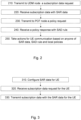
- a method for dynamically handling access and mobility service areas with different capabilities in a communication system 100 may be implemented in a core network, e.g. the core network 110.
- the method may be carried out at the AMF node 111 and will be described with reference to Figure 2 .
- the method comprises the following actions which may be performed in any suitable order.
- the AMF node 111 When a UE, e.g. the UE 120 enters into service areas of a base station, the AMF node 111 receives a registration request from the UE via the base station 130. After the registration request, in order to handle the communication for the UE 120, the AMF node 111 transmits to the UDM node 112, a subscription data request for the UE 120 communication.
- the Service Area Restriction (SAR) data for a subscriber includes a number of service areas allowed or restricted for the subscriber. Further, for each service area, the UE's subscription data in the UDM includes a service area identity, a service area type and a service area definition.
- SAR Service Area Restriction
- the AMF node 111 receives from the UDM node 112, subscription data with Service Area Restriction (SAR) data for the UE.
- SAR data includes a number of service areas allowed or restricted for the UE and, for each service area, a service area identifier, a service area type and a service area definition.
- the service area definition may be specified by using explicit Tracking Area identities (TAls).
- the core network may determine access and mobility service areas based on dynamic information received from the PCF node 113.
- the AMF node 111 may determine a set of service area characteristics during the interactions with the PCF node 113.
- the AMF node 111 transmits to the PCF node 113, a policy request about access and mobility service areas for the UE 120.
- the AMF node 111 receives, from the PCF node 113, a policy response with a Service Area Definition (SAD) rule for the UE 120.
- SAD Service Area Definition
- the SAD rule comprises a service area definition and an indication of a set of service area characteristics enabled in the service area.
- the SAD rule may also comprise one or more Network Slice Selection Assistance Information (NSSAI) that the service area applies to.
- NSSAI Network Slice Selection Assistance Information
- the AMF node 111 takes actions for the UE communication based on anyone of the SAR data, the SAD rule and local policies at the AMF node.
- the local policies at the AMF node 111 may define default values of the SAD rule when not provided by the PCF, and/or specify default actions to be taken for specific services areas or TAls.
- the AMF node 111 may take actions as per the Selected Service Area defined by TAls. These actions may include, but not limited to:
- a method carried out at a UDM node 112 in a core network for dynamically handling access and mobility service areas with different capabilities in a communication system will be described with reference to Figure 3 .
- the method comprises the following actions:
- the UDM node 112 configures SAR data for a UE 120.
- the SAR data includes a number of service areas allowed or restricted for the UE 120 and, for each service area, a service area identifier, a service area type and a service area definition.
- the number of service areas allowed or restricted for the UE indicates respective services allowed or restricted for the UE in each service area.
- the service area type may be any one of secure area, sponsored area, parental control area and dynamic area.
- the service area definition may comprise one or more tracking area identifier (TAI) identifying one or more TA that the service area comprises.
- TAI tracking area identifier
- the UDM node 112 receives from an AMF node 111 a subscription data request for the UE 120.
- the UDM node 112 transmits to the AMF node 111 subscription data with the SAR data for the UE 120.
- a method carried out at a PCF node 113 in a core network 110 for dynamically handling access and mobility service areas with different restrictions capabilities in a communication system 100 will be described with reference to Figure 4 .
- the method comprises the following actions:
- the PCF node 113 configures a Service Area Definition (SAD) rule for a UE.
- SAD rule comprises a service area definition, e.g. a list of TAls, and an indication of a set of service area characteristics enabled in the service area.
- the SAD rule may comprise one or more Network Slice Selection Assistance Information (NSSAI) that the service area applies to, e.g. a list of S-NSSAIs.
- NSSAI Network Slice Selection Assistance Information
- the SAD rule may further comprise events that trigger a re-evaluation of the access and mobility service area policies, e.g. location change, change of allowed S-NSSAI, etc.
- the PCF may configure the SAD rule based on the information received from the AMF node 111 in the AM Policy Association, static configuration, e.g. operator policies or during interaction with OTT/AF via a NEF node.
- the PCF node 113 receives from the AMF node 111, a policy request for the UE 120.
- the PCF node 113 transmits to the AMF node 111, a policy response with the SAD rule for the UE 120.
- the PCF node 113 configures the SAD rule, e.g. determines a set of service area characteristics, i.e. the set of functionalities enabled in the service area during interactions with the OTT/AF.
- the method may further comprise the following actions:
- the PCF node 113 may receive a Service Area Profile from provisioning system used by the service provider to update the configuration and subscription data in the core network nodes.
- Provisioning system uses Command Line Interface (CLI) or Application Programming Interface (API) to directly make configuration changes in the core network nodes.
- CLI Command Line Interface
- API Application Programming Interface
- the PCF node 113 may receive a Service Area Profile from the NEF node 114.
- the NEF node 114 may receive the Service Area Profile from any one of Operator Application Function, OTT Application Function, Data Analytics Function or Government Regulatory body.
- the OTT/AF via the NEF node 114 may issue requests to the PCF node 113 to manage, e.g. create, modify, or remove access and mobility service areas.
- the OTT/AF may issue requests on behalf of applications not owned by the PLMN serving the UE.
- the method may further comprise the following actions:
- the PCF node 113 may create a service area on-demand based on the received Service Area Profile.
- the OTT/AF provides a Service Area Profile, which may include:
- the PCF node 113 may update dynamically Service Area Restriction based on the received Service Area Profile.
- the PCF node 113 may update type of Service Area where a subscriber is currently located. It may also update the Service Area itself. These inputs regarding service area may be provided by the provisioning system or by the NEF node 114.
- the external Application Function may not be aware of the network based location details, i.e. TAls, cells, base stations gNBs etc. So, it may provide the actual geographical location, e.g. Latitude & Longitude to NFs. But NFs do not understand these details. So, mapping of these parameters is needed. This may be done at the NEF node or may be at the PCF node.
- mapping between geographical location e.g. Latitude & longitude, and Network location e.g. TAls is done via provisioning system. Then provisioning system updates the PCF node or NEF node with the mapping of geographical location and Network location. It may be decided based on solution deployment, at which point this mapping will be done. This means that translation from geographical location to network location TAls may also be done at the NEF or at the PCF as alternative.
- the AF may provide Service Area Profile with a message Nnef_ParameterProvision_Update to the NEF node 114.
- the Service Area Profile may include:
- the NEF node 114 then updates the PCF node 113 about SAR. It may use the same location information provided by the AF or it may provide a list of TAls based on where the mapping is configured.
- the PCF node 113 Based on the mapping, the PCF node 113 then updates other NFs, e.g. AMF node 111 or SMF node about SAR. Procedures between the PCF node and other NFs will be described in the following section.
- the Service Area Profile may be directly provisioned in the PCF node 113 by the provisioning system instead of providing it as a part of service request from the NEF node 114.
- a method carried out at a SMF node e.g. the SMF node 115 in a core network for dynamically handling access and mobility service areas with different capabilities in a communication system 100 will be described with reference to Figure 5 .
- the method comprises the following actions:
- the SMF node 115 receives from the AMF node 111, a session request for a UE communication.
- the session request includes service area related information with a service area identifier and a service area type.
- the service area related information may comprise any one of:
- the SMF node 115 receives from the PCF node 113, a policy response with a Service Area Definition (SAD) rule for the UE 120.
- the SAD rule comprises a service area definition and an indication of a set of service area characteristics enabled in the service area.
- the SMF node 115 takes actions for the UE communication based on the SAD rule, the information received from the AMF node (111) and/or local policies at the SMF node 115. That is, in relation to the access and mobility service areas, the SMF node 115 combines the input received from the AMF node 111 with the input received from the PCF node and/or own information.
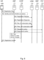
- Figure 6 shows an updated signaling flow for Registration procedure.
- a method performed in a core network 110 for dynamically defining access and mobility service areas during registration procedure a communication system 100 will be described with reference to Figure 6 .
- the method comprises the following steps or actions:
- the AMF node 111 takes actions based on anyone of the SAR data, the SAD rule and local policies at the AMF node.
- the AMF node 111 may take actions to make service changes as per the Selected Service Area defined by TAls. These actions may include, but not limited to:
- the AMF node 111 determines if the registration request is accepted or rejected based on the requirement of the service area and informs the UE 120.
- Figure 7 shows an updated signaling flow for Session Management. A method performed in a core network 110 for dynamically defining access and mobility service areas during session management procedure a communication system 100 will be described with reference to Figure 7 .
- the method comprises the following steps or actions:
- the AMF node 111 sends a PDU Session Establishment Request by sending a N smf _ PDUSession_CreateSMContext Request message to the SMF node 115 including Subscription Permanent Identifier (SUPI), Data Network Name (DNN), S-NSSAI, PDU Session ID, AMFID, Access Network Type (ANType), Request Type, SMContextStatusUri, N1 SM container etc. parameters as described in 3GPP TS 23.502.
- the request creates an individual SM context for a given PDU.
- the Service Area related information may be included in the Nsmf_PDUSession_CreateSMContext Request message.
- the Service Area related information may include:
- the SMF node responds with a Nsmf_PDUSession_CreateSMContext Response message to the AMF node 111 including SM Context ID.
- the AMF node 111 receives from the SMF node the response message.
- the SMF node 115 may perform a Session Management Policy Establishment procedure to establish a session with the selected PCF node 113 and get a default PCC Rules for the session.
- the SMF node sends a Session Management Policy Establishment Request message Npcf_SMPolicyControl Create Req. to the PCF node.
- the PCF node responds with a Session Management Policy Establishment Response message Npcf_SMPolicyControl Create Rsp. to the SMF node to provide service area characteristics to the SMF node.
- the PCF node may provide policies as per "Service Area”. It may also provide any special characteristics of that service Area. For the PDU session, the service area characteristics may include:
- the SMF node 115 may update the subscriber services according to the service area characteristics received from the PCF node 113 and the Service Area related information for the session received from the AMF node 111.
- the updating may comprise any one of disabling streaming services, activating LI for the subscriber, blocking some sites, providing sponsor data connectivity, or rejecting the session.
- a "Secure Area" e.g. FBI Headquarters
- video streaming apps might be disabled.
- LI for the subscriber might be activated.
- all pornographic sites are blocked for all users.
- SMF node may reject the session if it is not able to meet the mandatory requirement of "Service Area". For example, if LI is mandatary for a "Service Area" and the SMF node 115 is not able to support that, it may reject the session.
- the SMF node 115 initiates a UPF selection procedure according to a local configuration.
- the SMF node 115 initiates an N4 Session Establishment procedure with the selected UPF node.
- the SMF node 115 sends a Namf_Communication_N1N2_msg_Transfer Request message to the AMF node 111 including a N1 PDU Session Establishment Accept and N2 PDU Session Resource Setup Request Transfer messages.
- the AMF node 111 responds a Namf_Communication_N1N2_msg Transfer Response message to the SMF node 115.
- the AMF node 111 accepts or rejects the session as per the information received from the SMF node 115.
- the AMF node 111 determines accepting or rejecting the session based on the Transfer Request message received from the SMF node.
- the methods may be carried out in an AMF node 111, a UDM node 112, a PCF node 113 and a SMF node 115.
- the UDM node 112 may configure Service Area Restriction (SAR) data in a subscription data for a UE 120.
- the SAR data includes a number of service areas allowed or restricted for the UE and, for each service area, a service area identifier, a service area type and a service area definition.
- the PCF node may configure a Service Area Definition (SAD) rule for a UE.
- SAD Service Area Definition
- the SAD rule comprises a service area definition and an indication of a set of service area characteristics enabled in the service area, one or more NSSAI that the service area applies to.
- the PCF node may receive a Service Area Profile from provisioning system or from NEF and update dynamically SAR based on the received Service Area Profile.
- the PCF node may create a service area on-demand based on the received Service Area Profile.
- the SAR data and SAD rule may be provided to the AMF node upon request for a UE communication.
- the AMF node then takes actions for the UE communication based on anyone of the SAR data, the SAD rule and local policies at the AMF node.
- the embodiments herein allow flexible definition of access and mobility service areas with different capabilities, for specific network slices, for different subscribers based on the different use cases.
- the embodiments herein also provide new solutions to OTT/AF players to manage the business needs in real-time for use cases such as security, sponsoring and parental control.
Landscapes
- Engineering & Computer Science (AREA)
- Computer Networks & Wireless Communication (AREA)
- Signal Processing (AREA)
- Computer Security & Cryptography (AREA)
- Databases & Information Systems (AREA)
- Computer Hardware Design (AREA)
- General Engineering & Computer Science (AREA)
- Technology Law (AREA)
- Mobile Radio Communication Systems (AREA)
Description
- Embodiments herein relate to handling access and mobility service areas in a core network. In particular, they relate to Access & Mobility Restriction Control in a communication system.
- A Universal Mobile Telecommunications System (UMTS) is a third generation (3G) telecommunication network, which evolved from the second generation (2G) Global System for Mobile Communications (GSM). Specifications for the Evolved Packet System (EPS), also called a Fourth Generation (4G) network or Long Term Evolution (LTE), have been completed within the 3rd Generation Partnership Project (3GPP) and this work continues in the coming 3GPP releases, for example to specify a Fifth Generation (5G) New Radio (NR) network.
- 3GPP TS 23.501 defines
Stage 2 system architecture for 5G System. One of the new features introduced in the area of user equipment (UE) mobility consists of supporting Mobility Restrictions. Mobility Restrictions restrict mobility handling or service access of a UE. Mobility Restrictions consists of Radio Access Technology (RAT) restriction, Forbidden Area, Service Area Restrictions (SAR) and Core Network type restriction. - RAT restriction defines the 3GPP Radio Access Technology, a UE is not allowed to access in a Public Land Mobile Network (PLMN).
- In a Forbidden Area, a UE, based on subscription, is not permitted to initiate any communication with the network.
- Service Area Restriction defines areas in which a UE may or may not initiate communication with the network as follows:
- a) Allowed Area: a UE is permitted to initiate communication with the network as allowed by the subscription. The UE is registered in the network and update its location over Non-Access-Stratum (NAS), and can initiate session by e.g. a service request.
- b) Non-Allowed Area: a UE is service area restricted based on subscription. The UE is allowed to register in the network and update its location, but cannot initiate communication. The UE and the network are not allowed to initiate Service Request i.e. no session management.
- Core Network type restriction defines whether a UE is allowed to connect to 5G core network only (5GC), Evolved Packet Core (EPC) only, the core network of the LTE system, or both 5GC and EPC for this PLMN.
- The core network determines the Mobility Restrictions based on UE subscription information, UE location and local policy. 5G Core Network Functions (NFs) comprises the following nodes:
- Access and Mobility Management function (AMF).
- Session Management function (SMF).
- User plane function (UPF).
- Policy Control Function (PCF).
- Authentication Server Function (AUSF).
- Unified Data Management (UDM).
- Application Function (AF).
- Network Exposure function (NEF).
- NF Repository function (NRF).
- Network Slice Selection Function (NSSF).
- The UDM stores the Service Area Restrictions of a UE as part of the UE's subscription data. The PCF in the serving network may e.g. due to varying conditions such as UE's location, application in use, time and date further adjust Service Area Restrictions of a UE. In this respect, 3GPP TS 23.503 V16.3.0 defines a policy and charging control framework for the 5G System. During registration, if the Service Area Restrictions of the UE is not present in the AMF, the AMF fetches from the UDM the Service Area Restrictions of the UE that may be further adjusted by the PCF. The serving AMF shall enforce the Service Area Restrictions of a UE. For more details, see 3GPP TS 23.501, chapter 5.3.4.1. In addition,
CN 109 548 178 A (29 March 2019 ) discloses the AMF fetching subscription data from a UDM for a UE. - Access and mobility restrictions are not specified by 3GPP in 4G, but implemented mainly by node specific configuration, which created a lot of vendor specific implementations.
- Registration area management in 5G is based on the concept of mobility restrictions, with the objective to restrict mobility handling or service access of a UE. For example:
- a) For stationary or low mobility users, the "Allowed area" can be limited, and thus allow a lower price subscription.
- b) For enhanced Mobile Broadband (eMBB) users and high mobility users, no restrictions are applied.
- c) For users accessing the network only via a fixed point, for instance, the "Allowed area" may be limited to only one Tracking Area (TA).
- However, the current solution in 3GPP is limited to define either allowed or non-allowed areas. In addition, Allowed or Non-allowed areas apply to UE communication capability regardless of network slicing. 5GC network handles service area restrictions during registration and handover procedures, after network slice selection procedures. The AMF assigns service area restrictions to a UE that apply to all network slices the UE is currently attached to. Finally, service area restrictions are statically defined in the UDM and can only be adjusted by the PCF via operator policies.
- Therefore it is an object of the invention herein to improve handling access and mobility restrictions in a communication system.
- According to one aspect of embodiments herein, the object is achieved by an AMF node and method performed therein in a core network for dynamically handling access and mobility service areas with different capabilities in a communication system. The AMF node transmits to a UDM node, a subscription data request for a UE communication. The AMF node receives from the UDM node, subscription data with SAR data for the UE. The SAR data includes a number of service areas allowed or restricted for the UE and, for each service area, a service area identifier, a service area type and a service area definition. The service area type may be any one of: secure area, sponsored area, parental control area and dynamic area. The AMF node transmits to a PCF node, a policy request for the UE. The AMF node receives from the PCF node a policy response with a Service Area Definition (SAD) rule for the UE. The SAD rule comprises a service area definition and an indication of a set of service area characteristics enabled in the service area. The AMF node then take actions for the UE communication based on anyone of the SAR data, the SAD rule and local policies at the AMF node.
- According to one aspect of embodiments herein, the object is achieved by a UDM node and method performed therein in a core network for dynamically handling access and mobility service areas with different capabilities in a communication system. The UDM node configures SAR data for a UE. The SAR data includes a number of service areas allowed or restricted for the UE and, for each service area, a service area identifier, a service area type and a service area definition. The UDM node receives from the AMF node, a subscription data request for the UE and transmits to the AMF node the subscription data with the SAR data for the UE.
- Examples of embodiments herein are described in more detail with reference to attached drawings in which:
- Figure 1
- is a schematic block diagram depicting an example of a communication system;
- Figure 2
- is a flow chart illustrating a method performed in an AMF node according to claimed invention;
- Figure 3
- is a flow chart illustrating a method performed in a UDM node according to claimed invention;
- Figure 4
- is a flow chart illustrating a method performed in a PCF node according to embodiments herein;
- Figure 5
- is a flow chart illustrating a method performed in a SMF node according to embodiments herein;
- Figure 6
- is a signaling flow chart illustrating updated procedure for registration and session creation according to embodiments herein; and
- Figure 7
- is a signaling flow chart illustrating updated procedure for session management according to embodiments herein;
- As a part of developing embodiments herein some problems or limitations associated with the existing solutions will be first identified and discussed.
- As discussed in the background, the current solution in 3GPP is limited to define either allowed or non-allowed areas. There is no means to define service areas with restricted capabilities e.g. a Secure Area with limited functionality or with additional security checks. The limitation of Service Area Restriction (SAR) of providing service in limited manner, i.e. Allowed & Not-Allowed only, is addressed according to embodiments herein.
- In addition, Allowed or Non-allowed areas apply to UE communication capability regardless of network slicing. The PCF may further adjust Service Area Restrictions of a UE, but the update also applies to all network slices the UE is using.
- Access and mobility restrictions are not specified by 3GPP in 4G, but implemented mainly by node specific configuration. For example, the applicant has provided a proprietary solution with a dedicated interface between mobility management entity (MME) and Policy and Charging Rules Function (PCRF) for location-based policy control. However, this interface does not handle service area restrictions, as defined in 5G, but enables use cases such as:
- Dynamic allocation of the best radio resources on a per-user, per-terminal, per-location basis.
- Preferred access for subscribers.
- Dynamic selection of the Gateway GW based on, for example, the subscriber profile.
- There is no mechanism for over-the-top Adaptation Function (OTT/AF) to manage service area restrictions. Such mechanism will allow OTT/AF to create, modify, or remove service area restrictions on demand well suited for business cases driven by Enterprise or OTT/AF.
- Therefore according to embodiments herein, it is proposed to extend the concept of Service Area Restrictions (SAR), to allow flexible definition of service areas with different capabilities, for specific network slices, that can also be managed on demand by OTT/AF via NEF service exposure.
- Flexible Service Area can provide Network operator to manage the access & mobility function on certain triggers which are not fully utilized. There are many scenarios where different treatment of services is required based on Service Area requested.
- To describe this functionality, following examples of Service Areas may be considered:
- Secure Area: Area with high security, this may be office of government security agencies, e.g. Federal Bureau of Investigation (FBI) or office of leader of the nation e.g. white house.
- It may be required that, any subscriber entering this area should not be allowed to video upload or streaming websites. It may also be required that Lawful interception (LI) is enabled automatically for all subscriber which enters this sensitive area for real-time as well as offline analysis.
- It may also require that Equipment Identity Register (EIR) should be enabled for these subscribers, in case EIR is not used for all subscribers. Further restriction may be to disallow Grey List UEs or UEs without standard International Mobile Equipment Identity (IMEI). For example, in India, EIR check is an optional feature for the implementation or usage by operators as this decrease the revenue generation.
- Additionally, these services will be subscriber dependent as well. For example, Security officers, Diplomats, Very Important Person (VIP), basically trusted residents or office folks, in that area may not be affected by these policies.
- Sponsored Area: In some cases, an OTT player or operator itself may want to sponsor the services to subscribers. For example, all services used in an Industrial Trade fair might be paid by the sponsors of trade fair. So,
- Billing or Charging functionality needs to be updated accordingly.
- This may require that only certain Quality of Service (QoS) or quota is provided in this Area like at airport complimentary data surfing is allowed for "X" minutes with maximum speed capped at "Y Mbps".
- This may be specific to certain enterprises as well and only few services are sponsored.
- Parental Control Area: In some geographical areas like schools, library, college, academic institute etc., certain types of content can be blocked for all subscribers. People now implement this kind of control for individual subscribers e.g. students. But students may use mobile phones of other members of the house. So, it may be a good solution to restrict "explicit content" for all subscribers entering this area irrespective of age limit, subscription profile, etc.
- All new service areas defined above are more or less static in nature and predefined. Having said that, these Service areas can be dynamic in nature which can be changed or modified on the fly by operator or enterprise as per their use case and same is highlighted below.
- Dynamic Areas: All Service Areas can be used for static as well as dynamic Service area. For example, if considering Secure Area, this is similar to above service area, but this area might get modified dynamically. For example, if a president or king's envoy is moving to other location, e.g. from Palace to airport, then all the subscribers entering that area may be updated as per the Secure Area Policies.
- These areas may be implemented in two ways:
- Enumerated Lists: Different types of services areas may be defined which is represented by numbers so that all NFs recognize these areas and know which services to implement to subscribers which are in these area types. For example,
- a. ServiceAreaType=1 (Secure Area)
- b. ServiceAreaType=2 (Sponsored Area)
- c. ServiceAreaType=3 (Parental Control Area)
- Operator Defined: Other option is to use customized name or number for each type of service area. Also, what services to be implemented or removed for these areas is configured at each NF separately.
- It is also possible to use a combination of both of the above. Some area types maybe defined as universal types, e.g. 1 to 10 and remaining service areas may be set as operator defined.
- To implement the flexible Service Area, new parameters in UE subscription as well as update on PCF to AMF interface are proposed according to embodiments herein. This has impacts in both, the call flow for Registration and Session creation.
-
Figure 1 illustrates acommunication system 100 comprising a number of network nodes. Thecommunication system 100 comprises acore network 110 comprising a number of core network function nodes, such as anAMF node 111, aUDM node 112, aPCF node 113, an AF/NEF node 114, aSMF node 115 etc. Thecommunication system 100 further comprises a number of UEs and base stations, where aUE 120 and abase station 130 are shown. - Access and mobility service areas consist of a set of tracking areas where a UE is allowed to register and establish communication services with certain capabilities that make it suitable for certain scenarios or applications. For example, the operator may need to define certain service areas to provide communication services to the government or sensitive agencies that require fulfilling stringent security protocols. In such "secure areas" the network enables certain functionalities that are not typically required in the whole PLMN or network slice, such as secondary authentication or authorization, UE tracing and logging, lawful interception, etc.
- As described above, a few examples of service areas with specific capabilities may be Secure Area with limited capacity and additional security features, Sponsored Area where OTT/AF can create, remove or manage the respective service area, Parental Control Area where certain types of content can be blocked for all subscribers. All Service Areas may be used for static as well as dynamic Service area where different capabilities may be modified dynamically.
- A method for dynamically handling access and mobility service areas with different capabilities in a
communication system 100 according to embodiment herein may be implemented in a core network, e.g. thecore network 110. The method may be carried out at theAMF node 111 and will be described with reference toFigure 2 . The method comprises the following actions which may be performed in any suitable order. - When a UE, e.g. the
UE 120 enters into service areas of a base station, theAMF node 111 receives a registration request from the UE via thebase station 130. After the registration request, in order to handle the communication for theUE 120, theAMF node 111 transmits to theUDM node 112, a subscription data request for theUE 120 communication. At the UDM node, the Service Area Restriction (SAR) data for a subscriber includes a number of service areas allowed or restricted for the subscriber. Further, for each service area, the UE's subscription data in the UDM includes a service area identity, a service area type and a service area definition. - The
AMF node 111 receives from theUDM node 112, subscription data with Service Area Restriction (SAR) data for the UE. The SAR data includes a number of service areas allowed or restricted for the UE and, for each service area, a service area identifier, a service area type and a service area definition. The service area definition may be specified by using explicit Tracking Area identities (TAls). - The number of service areas allowed or restricted for the UE indicates respective services allowed or restricted for the UE in each service area.
- The service area type may be any one of secure area, sponsored area, parental control area and dynamic area.
- The service area definition may comprise one or more TAls identifying one or more Tracking Areas (TAs) that the service area comprises.
- The
AMF node 111 may determine a set of service area characteristics, i.e. a set of functionalities enabled in the service area by means of the configuration SAR data received from theUDM node 112, e.g. by mapping the service area identity and type to a pre-configured set of functionalities using, e.g. enumerated lists of different types of services areas representing Secure area, Sponsored area, Parental Control Area etc., or during interactions with thePCF node 113. - The service area characteristics may comprise any one or any combination of elements listed in the following:
- a) An indication that lawful interception is enabled in a service area;
- b) Address of Equipment Identity Register, EIR, to be used in a service area;
- c) Service blacklist comprising a set of IP flows or application identifiers that are not allowed in a service area;
- d) Sponsor Area Connectivity Profile to be used in a service area, which comprise Sponsor Identity, a set of sponsored services, a usage threshold that the sponsor expects the PCF to enforce, and/or Application Service Provider (ASP) address to report usage monitoring events;
- e) An indication that Parental Control is enabled, and access to explicit content is restricted in a service area.
- The core network may determine access and mobility service areas based on dynamic information received from the
PCF node 113. In this case, theAMF node 111 may determine a set of service area characteristics during the interactions with thePCF node 113. TheAMF node 111 transmits to thePCF node 113, a policy request about access and mobility service areas for theUE 120. - The
AMF node 111 receives, from thePCF node 113, a policy response with a Service Area Definition (SAD) rule for theUE 120. The SAD rule comprises a service area definition and an indication of a set of service area characteristics enabled in the service area. - The SAD rule may also comprise one or more Network Slice Selection Assistance Information (NSSAI) that the service area applies to.
- The
AMF node 111 takes actions for the UE communication based on anyone of the SAR data, the SAD rule and local policies at the AMF node. - The local policies at the
AMF node 111 may define default values of the SAD rule when not provided by the PCF, and/or specify default actions to be taken for specific services areas or TAls. - The
AMF node 111 may take actions as per the Selected Service Area defined by TAls. These actions may include, but not limited to: - a) Change of Network Slice to more secured network slice;
- b) Selection of EIR e.g. in the same network slice;
- c) Start of Lawful Interception (LI) etc.
- According to embodiments herein, a method carried out at a
UDM node 112 in a core network for dynamically handling access and mobility service areas with different capabilities in a communication system, will be described with reference toFigure 3 . The method comprises the following actions: - The
UDM node 112 configures SAR data for aUE 120. The SAR data includes a number of service areas allowed or restricted for theUE 120 and, for each service area, a service area identifier, a service area type and a service area definition. The number of service areas allowed or restricted for the UE indicates respective services allowed or restricted for the UE in each service area. The service area type may be any one of secure area, sponsored area, parental control area and dynamic area. The service area definition may comprise one or more tracking area identifier (TAI) identifying one or more TA that the service area comprises. - The
UDM node 112 receives from an AMF node 111 a subscription data request for theUE 120. - The
UDM node 112 transmits to theAMF node 111 subscription data with the SAR data for theUE 120. - According to embodiments herein, a method carried out at a
PCF node 113 in acore network 110 for dynamically handling access and mobility service areas with different restrictions capabilities in acommunication system 100, will be described with reference toFigure 4 . The method comprises the following actions: - The
PCF node 113 configures a Service Area Definition (SAD) rule for a UE. The SAD rule comprises a service area definition, e.g. a list of TAls, and an indication of a set of service area characteristics enabled in the service area. - The SAD rule may comprise one or more Network Slice Selection Assistance Information (NSSAI) that the service area applies to, e.g. a list of S-NSSAIs.
- The SAD rule may further comprise events that trigger a re-evaluation of the access and mobility service area policies, e.g. location change, change of allowed S-NSSAI, etc.
- The PCF may configure the SAD rule based on the information received from the
AMF node 111 in the AM Policy Association, static configuration, e.g. operator policies or during interaction with OTT/AF via a NEF node. - The
PCF node 113 receives from theAMF node 111, a policy request for theUE 120. - The
PCF node 113 transmits to theAMF node 111, a policy response with the SAD rule for theUE 120. - When the
PCF node 113 configures the SAD rule, e.g. determines a set of service area characteristics, i.e. the set of functionalities enabled in the service area during interactions with the OTT/AF. The method may further comprise the following actions: - The
PCF node 113 may receive a Service Area Profile from provisioning system used by the service provider to update the configuration and subscription data in the core network nodes. Provisioning system uses Command Line Interface (CLI) or Application Programming Interface (API) to directly make configuration changes in the core network nodes. - The
PCF node 113 may receive a Service Area Profile from theNEF node 114. TheNEF node 114 may receive the Service Area Profile from any one of Operator Application Function, OTT Application Function, Data Analytics Function or Government Regulatory body. - The OTT/AF via the
NEF node 114 may issue requests to thePCF node 113 to manage, e.g. create, modify, or remove access and mobility service areas. The OTT/AF may issue requests on behalf of applications not owned by the PLMN serving the UE. In this case, the method may further comprise the following actions: - The
PCF node 113 may create a service area on-demand based on the received Service Area Profile. - To create a service area, the OTT/AF provides a Service Area Profile, which may include:
- a) Geographical definition of the service area, e.g. longitude and latitude, zip code, etc.
- b) Service area type or a set of service area characteristics according to a previous agreement (SLA) reached between the network operator and the OTT.
- c) Applicability of the service area that may be either a group of UEs, i.e. a list of UE identities or an internal group identifier or all the UEs.
- The
PCF node 113 may update dynamically Service Area Restriction based on the received Service Area Profile. ThePCF node 113 may update type of Service Area where a subscriber is currently located. It may also update the Service Area itself. These inputs regarding service area may be provided by the provisioning system or by theNEF node 114. - The external Application Function (AF) may not be aware of the network based location details, i.e. TAls, cells, base stations gNBs etc. So, it may provide the actual geographical location, e.g. Latitude & Longitude to NFs. But NFs do not understand these details. So, mapping of these parameters is needed. This may be done at the NEF node or may be at the PCF node.
- Option 1: First, mapping between geographical location e.g. Latitude & longitude, and Network location e.g. TAls, is done via provisioning system. Then provisioning system updates the PCF node or NEF node with the mapping of geographical location and Network location. It may be decided based on solution deployment, at which point this mapping will be done. This means that translation from geographical location to network location TAls may also be done at the NEF or at the PCF as alternative.
- The AF may provide Service Area Profile with a message Nnef_ParameterProvision_Update to the
NEF node 114. The Service Area Profile may include: - a) Service Area Definition, e.g. geographical definition of the service area with Latitude & Longitude,
- b) Service area type or an explicit set of Service Area Characteristics, e.g. LI & service barring etc.
- c) The applicability of the service area that may be either a group of UEs or all the UEs.
- The
NEF node 114 then updates thePCF node 113 about SAR. It may use the same location information provided by the AF or it may provide a list of TAls based on where the mapping is configured. - Based on the mapping, the
PCF node 113 then updates other NFs, e.g.AMF node 111 or SMF node about SAR. Procedures between the PCF node and other NFs will be described in the following section. - Option 2: The Service Area Profile may be directly provisioned in the
PCF node 113 by the provisioning system instead of providing it as a part of service request from theNEF node 114. - According to embodiments herein, a method carried out at a SMF node, e.g. the
SMF node 115 in a core network for dynamically handling access and mobility service areas with different capabilities in acommunication system 100 will be described with reference toFigure 5 . The method comprises the following actions: - The
SMF node 115 receives from theAMF node 111, a session request for a UE communication. The session request includes service area related information with a service area identifier and a service area type. The service area related information may comprise any one of: - a) An indication that Lawful interception is enabled in a service area;
- b) Address of Equipment Identity Register (EIR) to be used in a service area;
- c) Sponsor Identity.
- The
SMF node 115 transmits to the PCF node 113 a policy request for theUE 120. - The
SMF node 115 receives from thePCF node 113, a policy response with a Service Area Definition (SAD) rule for theUE 120. The SAD rule comprises a service area definition and an indication of a set of service area characteristics enabled in the service area. - The set of service area characteristics may comprise any one of:
- a) A service blacklist with identifiers not allowed in the service area;
- b) A Sponsor Area Connectivity Profile, which includes anyone of a Sponsor Identity, a set of sponsored services, a usage threshold, and/or an address to report usage monitoring events; and
- c) An indication of whether parental control is enabled in the service area.
- The
SMF node 115 takes actions for the UE communication based on the SAD rule, the information received from the AMF node (111) and/or local policies at theSMF node 115. That is, in relation to the access and mobility service areas, theSMF node 115 combines the input received from theAMF node 111 with the input received from the PCF node and/or own information. - In the following, signaling flows for Registration and Session creation are described to see the impact of adding new capabilities related to the definition of flexible Service Areas.
-
Figure 6 shows an updated signaling flow for Registration procedure. A method performed in acore network 110 for dynamically defining access and mobility service areas during registration procedure acommunication system 100 will be described with reference toFigure 6 . - As described above, the following configurations are made at the
UDM node 112 and the PCF node 113: - UDM node 112: Service Area Restriction (SAR) data for a subscriber, which includes a number of service areas allowed or restricted for the subscriber and, for each service area, a service area identifier, a service area type and a service area definition.
- PCF node 113: Service area restriction profiles and the necessary rules and conditions that define when a service area restriction profile applies to a subscriber or groups of subscribers. A service area restriction profile consists of a service area identifier, a service area type and a service area definition.
- The method comprises the following steps or actions:
- 601: The
AMF node 111 receives from a UE 120 a registration request via abase station 130. - 602: The
AMF node 111 performs an Identity and Authentication procedure. This is a standard procedure. - 603: The
AMF node 111 initiates a registration request towards theUDM node 112, with a Nudm_UEContextManagement_Registration Request message. - 604: The
UDM node 112 provides a response according to registration details of theUE 120, with a Nudm_UEContextManagement_Registration Response message. - 605: The
AMF node 111 requires for subscription data from theUDM node 112 for theUE 120, with a Nudm_SubscriberDataManagement_Get Request message. The requested data is Access and Mobility Subscription data. - 606: The
UDM node 112 provides the subscription data with SAR data for theUE 120, with Nudm_SubscriberDataManagement_Get Response. The UDM node provides all subscription data for the subscriber. It also includes ServiceAreaRestriction (SAR) related data. This data currently includes whether subscribers is subscribed or not. According to embodiments herein, additional parameters for SAR are provided by theUDM node 112 to indicate that subscriber is allowed or disallowed for certain services. So the SAR data includes a number of service areas allowed or restricted for the UE, with parameter ServiceAreaRestrictions, and for each service area, a service area identifier, e.g. ServiceA area Identifier= 100, a service area type, e.g. ServiceAreaType=Secure_Area and a service area definition, e.g. ServiceAreaDefinition=TA1, TA2. - 607: After receiving the subscription data, the
AMF node 111 may send a policy request Npcf_AMPolicyControlCreat_Req to thePCF node 113 for policies about access and mobility service areas. - 608: The
PCF node 113 sends a response Npcf_AMPolicyControlCreat_Rsp and provides to the AMF node 111 a Service Area Definition (SAD) Rule for the UE. The SAD rule may comprise any one or a combination of:- A service area definition, e.g. a list of TAls;
- Service area type or an indication of a set of service area characteristics enabled in the service area;
- One or more Network Slice Selection Assistance Information (NSSAI) that the service area applies to, e.g. a list of Single NSSAI (S-NSSAls);
- Events that trigger a re-evaluation of the access and mobility service area policies, e.g. location change, change of allowed S-NSSAI, etc.
- The service area characteristics may comprise any one of:
- An indication that Lawful interception is enabled in a service area;
- Address of Equipment Identity Register (EIR) to be used in a service area;
- Sponsor Identity.
- 609: The
AMF node 111 takes actions based on anyone of the SAR data, the SAD rule and local policies at the AMF node. - The
AMF node 111 may take actions to make service changes as per the Selected Service Area defined by TAls. These actions may include, but not limited to: - Change of Network Slice to more secured network slice;
- Selection of EIR e.g. in the same network slice;
- Start of Lawful Interception (LI) etc.
- 610: After this, the
AMF node 111 determines if the registration request is accepted or rejected based on the requirement of the service area and informs theUE 120. -
Figure 7 shows an updated signaling flow for Session Management. A method performed in acore network 110 for dynamically defining access and mobility service areas during session management procedure acommunication system 100 will be described with reference toFigure 7 . - The method comprises the following steps or actions:
- 701: The
AMF node 111 receives from a UE 120 a session establishment request, e.g. a Protocol Data Unit (PDU) session in 5G. The session establishment request may include standard information including security, identity and slice information. - 702: The
AMF node 111 performs an Access & Mobility procedure and also selects the SMF node to be used for this session. - 703: The
AMF node 111 initiates a session request towards the selectedSMF node 115 to create an individual Session Management (SM) context for a given session. TheAMF node 111 provides Service Area related information for the session to the SMF node. - For example, the
AMF node 111 sends a PDU Session Establishment Request by sending a Nsmf_PDUSession_CreateSMContext Request message to theSMF node 115 including Subscription Permanent Identifier (SUPI), Data Network Name (DNN), S-NSSAI, PDU Session ID, AMFID, Access Network Type (ANType), Request Type, SMContextStatusUri, N1 SM container etc. parameters as described in 3GPP TS 23.502. The request creates an individual SM context for a given PDU. The Service Area related information may be included in the Nsmf_PDUSession_CreateSMContext Request message. - The Service Area related information may include:
- An indication that Lawful interception (LI) is enabled in the service area.
- Address of the Equipment Identity Register (EIR) to be used in the service area.
- Sponsor Identity if applicable.
- 704: The SMF node responds with a Nsmf_PDUSession_CreateSMContext Response message to the
AMF node 111 including SM Context ID. TheAMF node 111 receives from the SMF node the response message. - 705: If dynamic PCC is deployed, the SMF node performs a PCF selection.
- 706: The
SMF node 115 may perform a Session Management Policy Establishment procedure to establish a session with the selectedPCF node 113 and get a default PCC Rules for the session. The SMF node sends a Session Management Policy Establishment Request message Npcf_SMPolicyControl Create Req. to the PCF node. - 707: The PCF node responds with a Session Management Policy Establishment Response message Npcf_SMPolicyControl Create Rsp. to the SMF node to provide service area characteristics to the SMF node. The PCF node may provide policies as per "Service Area". It may also provide any special characteristics of that service Area. For the PDU session, the service area characteristics may include:
- Service blacklist to indicate i.e. a set of IP flows or application identifiers that are not allowed in the service area.
- The Sponsor Area Connectivity Profile to be used in the service area, which includes Sponsor Identity, a set of sponsored services, i.e. sponsored IP flows or application identifiers, a usage threshold that the sponsor expects the PCF node to enforce, and/or the ASP address to report usage monitoring events.
- An indication that Parental Control is enabled, and access to explicit content is restricted in the service area.
- 708: Based on above information, the
SMF node 115 may update the subscriber services according to the service area characteristics received from thePCF node 113 and the Service Area related information for the session received from theAMF node 111. The updating may comprise any one of disabling streaming services, activating LI for the subscriber, blocking some sites, providing sponsor data connectivity, or rejecting the session. For example, in a "Secure Area", e.g. FBI Headquarters, video streaming apps might be disabled. LI for the subscriber might be activated. Or in a School area all pornographic sites are blocked for all users. Further, SMF node may reject the session if it is not able to meet the mandatory requirement of "Service Area". For example, if LI is mandatary for a "Service Area" and theSMF node 115 is not able to support that, it may reject the session. - 709: The
SMF node 115 initiates a UPF selection procedure according to a local configuration. TheSMF node 115 initiates an N4 Session Establishment procedure with the selected UPF node. - 710: The
SMF node 115 sends a Namf_Communication_N1N2_msg_Transfer Request message to theAMF node 111 including a N1 PDU Session Establishment Accept and N2 PDU Session Resource Setup Request Transfer messages. - 711: The
AMF node 111 responds a Namf_Communication_N1N2_msg Transfer Response message to theSMF node 115. - 712: The
AMF node 111 accepts or rejects the session as per the information received from theSMF node 115. TheAMF node 111 determines accepting or rejecting the session based on the Transfer Request message received from the SMF node. - To summarize, methods performed in a
core network 110 for dynamically handling access and mobility service areas with different capabilities in acommunication system 100 are described. The methods may be carried out in anAMF node 111, aUDM node 112, aPCF node 113 and aSMF node 115. TheUDM node 112 may configure Service Area Restriction (SAR) data in a subscription data for aUE 120. The SAR data includes a number of service areas allowed or restricted for the UE and, for each service area, a service area identifier, a service area type and a service area definition. The PCF node may configure a Service Area Definition (SAD) rule for a UE. The SAD rule comprises a service area definition and an indication of a set of service area characteristics enabled in the service area, one or more NSSAI that the service area applies to. The PCF node may receive a Service Area Profile from provisioning system or from NEF and update dynamically SAR based on the received Service Area Profile. The PCF node may create a service area on-demand based on the received Service Area Profile. During a registration procedure, the SAR data and SAD rule may be provided to the AMF node upon request for a UE communication. The AMF node then takes actions for the UE communication based on anyone of the SAR data, the SAD rule and local policies at the AMF node. During a session management procedure, theSMF node 115 may receive service area related information with a service area identifier and a service area type from the AMF node, and receive the SAD rule from the PCF node. TheSMF node 115 then take actions for the UE communication based on the SAD rule, the information received from theAMF node 111 and/or local policies at the SMF node. - Therefore, the embodiments herein provide a mechanism to allow flexible definition of access and mobility service areas with different capabilities for e.g. 5G systems, for specific network slices, that can also be managed on demand by OTT/Enterprise via NEF service exposure. Few examples of service areas with specific capabilities are
- A. Secure Area, with limited capacity and additional security features, e.g. government security agencies.
- B. Sponsored Area, where OTT/Enterprise want to sponsor services to subscribers, e.g. data services provided in an Industrial Trade fair.
- C. Parental control service area, where certain type of content can be blocked for all subscribers, e.g. schools, library, college, university campus.
- The embodiments herein allow flexible definition of access and mobility service areas with different capabilities, for specific network slices, for different subscribers based on the different use cases. The embodiments herein also provide new solutions to OTT/AF players to manage the business needs in real-time for use cases such as security, sponsoring and parental control.
- When using the word "comprise" or "comprising" it shall be interpreted as nonlimiting, i.e. meaning "consist at least of".
Claims (11)
- A method for dynamically handling access and mobility service areas with different capabilities in a communication system, the method carried out by an Access and Mobility Management function, AMF, node (111) and comprising:Transmitting (210), to a Unified Data Management, UDM, node (112), a subscription data request for a user equipment, UE (120), communication;Receiving (220), from the UDM node (112), subscription data with Service Area Restriction, SAR, data for the UE, wherein the SAR data includes a number of service areas allowed or restricted for the UE and, for each service area, a service area identifier, a service area type, wherein the service area type identifies a service provided in the service area, and a service area definition, wherein the service area definition delimits the service area;Transmitting (230), to a Policy Control Function, PCF, node (113), a policy request for the UE (120);Receiving (240), from the PCF node (113), a policy response with a Service Area Definition, SAD, rule for the UE (120), wherein the SAD rule comprises a service area definition and an indication of a set of service area characteristics enabled in the service area, wherein the service area characteristics relate to the service provided in the service area; andTaking actions (250) for the UE communication based on anyone of the SAR data, the SAD rule and local policies at the AMF node.
- The method according to claim 1, wherein the service area type is any one of:
secure area, sponsored area, parental control area and dynamic area. - The method according to any one of claims 1 or 2, wherein the service area definition comprises one or more tracking area, TA, identifier identifying one or more TA that the service area comprises.
- The method according to any one of claims 1 to 3, wherein the SAD rule comprises one or more Network Slice Selection Assistance Information, NSSAI, that the service area applies to.
- A method for dynamically handling access and mobility service areas with different capabilities in a communication system, the method carried out by a Unified Data Management, UDM, node (112), and comprising:Configuring (310) Service Area Restriction, SAR, data for a user equipment, UE (120), wherein the SAR data includes a number of service areas allowed or restricted for the UE and, for each service area, a service area identifier, a service area type, wherein the service area type identifies a service provided in the service area, and a service area definition, wherein the service area definition delimits the service area;Receiving (320), from an Access and Mobility Management function, AMF, node (111), a subscription data request for the UE; andTransmitting (330), to the AMF node (111), subscription data with the SAR data for the UE.
- The method according to claim 5, wherein the service area type is any one of:
secure area, sponsored area, parental control area and dynamic area. - The method according to any one of claims 5 or 6, wherein the service area definition comprises one or more tracking area, TA, identifier identifying one or more TA that the service area comprises.
- An Access and Mobility Management function, AMF, node (111) for use in a core network and for dynamically handling access and mobility service areas with different capabilities in a communication system, wherein the AMF node (111) is configured to:transmit to a Unified Data Management, UDM, node (112), a subscription data request for a user equipment, UE (120), communication;receive from the UDM node (112), subscription data with Service Area Restriction, SAR, data for the UE, wherein the SAR data includes a number of service areas allowed or restricted for the UE and, for each service area, a service area identifier, a service area type, wherein the service area type identifies a service provided in the service area, and a service area definition, wherein the service area definition delimits the service area;transmit to a Policy Control Function, PCF, node (113), a policy request for the UE (120);receive from the PCF node (113), a policy response with a Service Area Definition, SAD, rule for the UE (120), wherein the SAD rule comprises a service area definition and an indication of a set of service area characteristics enabled in the service area, wherein the service area characteristics relate to the service provided in the service area; andtake actions for the UE communication based on anyone of the SAR data, the SAD rule and local policies at the AMF node.
- The AMF node (111) according to claim 8, further configured to perform the method of any of claims 2 to 4.
- A Unified Data Management, UDM, node (112) for use in a core network (110) and for dynamically handling access and mobility service areas with different capabilities in a communication system (100), wherein the UDM node (112) is configured to:configure Service Area Restriction, SAR, data for a user equipment, UE (120), wherein the SAR data includes a number of service areas allowed or restricted for the UE and, for each service area, a service area identifier, a service area type, wherein the service area type identifies a service provided in the service area, and a service area definition, wherein the service area definition delimits the service area;receive from an Access and Mobility Management function, AMF, node (111), a subscription data request for the UE; andtransmit to the AMF node (111), subscription data with the SAR data for the UE.
- The UDM node (112) according to claim 10, further configured to perform the method of any of claims 6 to 7.
Applications Claiming Priority (1)
| Application Number | Priority Date | Filing Date | Title |
|---|---|---|---|
| PCT/EP2020/052378 WO2021151499A1 (en) | 2020-01-31 | 2020-01-31 | Method and system for including dynamic service areas in access & mobility restriction control |
Publications (2)
| Publication Number | Publication Date |
|---|---|
| EP4097950A1 EP4097950A1 (en) | 2022-12-07 |
| EP4097950B1 true EP4097950B1 (en) | 2025-04-16 |
Family
ID=69468542
Family Applications (1)
| Application Number | Title | Priority Date | Filing Date |
|---|---|---|---|
| EP20703707.8A Active EP4097950B1 (en) | 2020-01-31 | 2020-01-31 | Method and system for including dynamic service areas in access & mobility restriction control |
Country Status (3)
| Country | Link |
|---|---|
| US (1) | US12382366B2 (en) |
| EP (1) | EP4097950B1 (en) |
| WO (1) | WO2021151499A1 (en) |
Families Citing this family (4)
| Publication number | Priority date | Publication date | Assignee | Title |
|---|---|---|---|---|
| WO2022064264A1 (en) * | 2020-09-28 | 2022-03-31 | Telefonaktiebolaget Lm Ericsson (Publ) | Network-initiated slice-based session handover |
| WO2022195461A1 (en) * | 2021-03-15 | 2022-09-22 | Lenovo (Singapore) Pte. Ltd. | Registration authentication based on a capability |
| WO2023037220A1 (en) * | 2021-09-08 | 2023-03-16 | Lenovo (Singapore) Pte. Ltd. | Determining release information based on registration information |
| US12627582B2 (en) * | 2022-01-21 | 2026-05-12 | Telefonaktiebolaget Lm Ericsson (Publ) | Methods, apparatus and computer-readable medium for monitoring site access over a mobile communication network |
Family Cites Families (7)
| Publication number | Priority date | Publication date | Assignee | Title |
|---|---|---|---|---|
| US20120008604A1 (en) * | 2010-07-09 | 2012-01-12 | Nokia Corporation | Enablement for reallocated bandwidth environments |
| US10986602B2 (en) * | 2018-02-09 | 2021-04-20 | Intel Corporation | Technologies to authorize user equipment use of local area data network features and control the size of local area data network information in access and mobility management function |
| US20210084569A1 (en) * | 2018-05-11 | 2021-03-18 | Lg Electronics Inc. | Method for updating ladn information in wireless communication system and device therefor |
| CN109548178B (en) * | 2018-12-26 | 2022-02-08 | 腾讯科技(深圳)有限公司 | Communication method and network equipment |
| WO2020171529A1 (en) * | 2019-02-22 | 2020-08-27 | Lg Electronics Inc. | Method for performing communication related to packet switch data off |
| US11363447B2 (en) * | 2019-08-01 | 2022-06-14 | Verizon Patent And Licensing Inc. | Method and device for managing and allocating binding service in a wireless network |
| CN114788316A (en) * | 2019-11-08 | 2022-07-22 | Lg 电子株式会社 | Network control method for sending UE strategy |
-
2020
- 2020-01-31 US US17/790,995 patent/US12382366B2/en active Active
- 2020-01-31 WO PCT/EP2020/052378 patent/WO2021151499A1/en not_active Ceased
- 2020-01-31 EP EP20703707.8A patent/EP4097950B1/en active Active
Also Published As
| Publication number | Publication date |
|---|---|
| EP4097950A1 (en) | 2022-12-07 |
| US12382366B2 (en) | 2025-08-05 |
| US20230013118A1 (en) | 2023-01-19 |
| WO2021151499A1 (en) | 2021-08-05 |
Similar Documents
| Publication | Publication Date | Title |
|---|---|---|
| US12082102B2 (en) | Multimedia priority service for wireless devices | |
| US11818608B2 (en) | Third party charging in a wireless network | |
| EP3817423B1 (en) | Network access method, related device, and system | |
| US20230189192A1 (en) | Access to Second Network by Wireless Device | |
| US20230422142A1 (en) | Collaboration Between Mobile Network Operators for Mobile Edge Computing Applications | |
| EP4101188A1 (en) | Extension of npcf_eventexposure with usage monitoring event | |
| CN107615732B (en) | Method and mobility management functional entity for admitting session into virtual network | |
| EP3787341B1 (en) | Method for selecting a session management entity for serving a wireless communication device | |
| US12382366B2 (en) | Method and system for including dynamic service areas in access and mobility restriction control | |
| CN113228570A (en) | Providing VLAN IDs in 5G systems | |
| WO2020224622A1 (en) | Information configuration method and device | |
| US11510024B2 (en) | System and method for geo-fencing of fixed wireless access | |
| US20230388909A1 (en) | Ensuring network control of simultaneous access to network slices with application awareness | |
| KR20230137998A (en) | New method for provisioning external parameters for AF sessions | |
| US20240276200A1 (en) | Network capability exposure method, apparatus, and system | |
| WO2020155048A1 (en) | Packet switch (ps) data off feature initiated in a network | |
| US20250113216A1 (en) | Dynamic retrieval of nsac information | |
| CN118803614A (en) | Communication method and communication device | |
| EP4135376A1 (en) | Method and device for secure communication | |
| US11606303B1 (en) | Device initiated quality of service | |
| WO2024081679A1 (en) | Accessing localized services in a wireless communication system | |
| WO2024105576A1 (en) | Serving network location based validity condition for localized service and enhanced sor procedure for localized service | |
| CN117897983A (en) | Method for access and mobility policy decisions | |
| WO2022013601A1 (en) | Provisioning drone flight in 5g networks | |
| US20240349177A1 (en) | Method for network selection based on slice information |
Legal Events
| Date | Code | Title | Description |
|---|---|---|---|
| STAA | Information on the status of an ep patent application or granted ep patent |
Free format text: STATUS: UNKNOWN |
|
| STAA | Information on the status of an ep patent application or granted ep patent |
Free format text: STATUS: THE INTERNATIONAL PUBLICATION HAS BEEN MADE |
|
| PUAI | Public reference made under article 153(3) epc to a published international application that has entered the european phase |
Free format text: ORIGINAL CODE: 0009012 |
|
| STAA | Information on the status of an ep patent application or granted ep patent |
Free format text: STATUS: REQUEST FOR EXAMINATION WAS MADE |
|
| 17P | Request for examination filed |
Effective date: 20220808 |
|
| AK | Designated contracting states |
Kind code of ref document: A1 Designated state(s): AL AT BE BG CH CY CZ DE DK EE ES FI FR GB GR HR HU IE IS IT LI LT LU LV MC MK MT NL NO PL PT RO RS SE SI SK SM TR |
|
| DAV | Request for validation of the european patent (deleted) | ||
| DAX | Request for extension of the european patent (deleted) | ||
| STAA | Information on the status of an ep patent application or granted ep patent |
Free format text: STATUS: EXAMINATION IS IN PROGRESS |
|
| 17Q | First examination report despatched |
Effective date: 20240403 |
|
| REG | Reference to a national code |
Ref country code: DE Ref legal event code: R079 Free format text: PREVIOUS MAIN CLASS: H04L0029080000 Ipc: H04W0048160000 Ref document number: 602020049496 Country of ref document: DE |
|
| GRAP | Despatch of communication of intention to grant a patent |
Free format text: ORIGINAL CODE: EPIDOSNIGR1 |
|
| STAA | Information on the status of an ep patent application or granted ep patent |
Free format text: STATUS: GRANT OF PATENT IS INTENDED |
|
| RIC1 | Information provided on ipc code assigned before grant |
Ipc: H04W 12/80 20210101ALI20240919BHEP Ipc: H04L 67/50 20220101ALI20240919BHEP Ipc: H04L 67/30 20220101ALI20240919BHEP Ipc: H04L 67/142 20220101ALI20240919BHEP Ipc: H04W 4/50 20180101ALI20240919BHEP Ipc: H04W 48/16 20090101AFI20240919BHEP |
|
| INTG | Intention to grant announced |
Effective date: 20241022 |
|
| GRAS | Grant fee paid |
Free format text: ORIGINAL CODE: EPIDOSNIGR3 |
|
| GRAA | (expected) grant |
Free format text: ORIGINAL CODE: 0009210 |
|
| STAA | Information on the status of an ep patent application or granted ep patent |
Free format text: STATUS: THE PATENT HAS BEEN GRANTED |
|
| AK | Designated contracting states |
Kind code of ref document: B1 Designated state(s): AL AT BE BG CH CY CZ DE DK EE ES FI FR GB GR HR HU IE IS IT LI LT LU LV MC MK MT NL NO PL PT RO RS SE SI SK SM TR |
|
| REG | Reference to a national code |
Ref country code: GB Ref legal event code: FG4D |
|
| REG | Reference to a national code |
Ref country code: CH Ref legal event code: EP Ref country code: DE Ref legal event code: R096 Ref document number: 602020049496 Country of ref document: DE |
|
| REG | Reference to a national code |
Ref country code: IE Ref legal event code: FG4D |
|
| REG | Reference to a national code |
Ref country code: NL Ref legal event code: MP Effective date: 20250416 |
|
| PG25 | Lapsed in a contracting state [announced via postgrant information from national office to epo] |
Ref country code: NL Free format text: LAPSE BECAUSE OF FAILURE TO SUBMIT A TRANSLATION OF THE DESCRIPTION OR TO PAY THE FEE WITHIN THE PRESCRIBED TIME-LIMIT Effective date: 20250416 |
|
| REG | Reference to a national code |
Ref country code: AT Ref legal event code: MK05 Ref document number: 1786714 Country of ref document: AT Kind code of ref document: T Effective date: 20250416 |
|
| PG25 | Lapsed in a contracting state [announced via postgrant information from national office to epo] |
Ref country code: FI Free format text: LAPSE BECAUSE OF FAILURE TO SUBMIT A TRANSLATION OF THE DESCRIPTION OR TO PAY THE FEE WITHIN THE PRESCRIBED TIME-LIMIT Effective date: 20250416 Ref country code: PT Free format text: LAPSE BECAUSE OF FAILURE TO SUBMIT A TRANSLATION OF THE DESCRIPTION OR TO PAY THE FEE WITHIN THE PRESCRIBED TIME-LIMIT Effective date: 20250818 Ref country code: ES Free format text: LAPSE BECAUSE OF FAILURE TO SUBMIT A TRANSLATION OF THE DESCRIPTION OR TO PAY THE FEE WITHIN THE PRESCRIBED TIME-LIMIT Effective date: 20250416 |
|
| REG | Reference to a national code |
Ref country code: LT Ref legal event code: MG9D |
|
| PG25 | Lapsed in a contracting state [announced via postgrant information from national office to epo] |
Ref country code: GR Free format text: LAPSE BECAUSE OF FAILURE TO SUBMIT A TRANSLATION OF THE DESCRIPTION OR TO PAY THE FEE WITHIN THE PRESCRIBED TIME-LIMIT Effective date: 20250717 Ref country code: NO Free format text: LAPSE BECAUSE OF FAILURE TO SUBMIT A TRANSLATION OF THE DESCRIPTION OR TO PAY THE FEE WITHIN THE PRESCRIBED TIME-LIMIT Effective date: 20250716 |
|
| PG25 | Lapsed in a contracting state [announced via postgrant information from national office to epo] |
Ref country code: PL Free format text: LAPSE BECAUSE OF FAILURE TO SUBMIT A TRANSLATION OF THE DESCRIPTION OR TO PAY THE FEE WITHIN THE PRESCRIBED TIME-LIMIT Effective date: 20250416 |
|
| PG25 | Lapsed in a contracting state [announced via postgrant information from national office to epo] |
Ref country code: BG Free format text: LAPSE BECAUSE OF FAILURE TO SUBMIT A TRANSLATION OF THE DESCRIPTION OR TO PAY THE FEE WITHIN THE PRESCRIBED TIME-LIMIT Effective date: 20250416 |
|
| PG25 | Lapsed in a contracting state [announced via postgrant information from national office to epo] |
Ref country code: HR Free format text: LAPSE BECAUSE OF FAILURE TO SUBMIT A TRANSLATION OF THE DESCRIPTION OR TO PAY THE FEE WITHIN THE PRESCRIBED TIME-LIMIT Effective date: 20250416 |
|
| PG25 | Lapsed in a contracting state [announced via postgrant information from national office to epo] |
Ref country code: AT Free format text: LAPSE BECAUSE OF FAILURE TO SUBMIT A TRANSLATION OF THE DESCRIPTION OR TO PAY THE FEE WITHIN THE PRESCRIBED TIME-LIMIT Effective date: 20250416 |
|
| PG25 | Lapsed in a contracting state [announced via postgrant information from national office to epo] |
Ref country code: RS Free format text: LAPSE BECAUSE OF FAILURE TO SUBMIT A TRANSLATION OF THE DESCRIPTION OR TO PAY THE FEE WITHIN THE PRESCRIBED TIME-LIMIT Effective date: 20250716 |
|
| PG25 | Lapsed in a contracting state [announced via postgrant information from national office to epo] |
Ref country code: IS Free format text: LAPSE BECAUSE OF FAILURE TO SUBMIT A TRANSLATION OF THE DESCRIPTION OR TO PAY THE FEE WITHIN THE PRESCRIBED TIME-LIMIT Effective date: 20250816 |
|
| PG25 | Lapsed in a contracting state [announced via postgrant information from national office to epo] |
Ref country code: LV Free format text: LAPSE BECAUSE OF FAILURE TO SUBMIT A TRANSLATION OF THE DESCRIPTION OR TO PAY THE FEE WITHIN THE PRESCRIBED TIME-LIMIT Effective date: 20250416 |
|
| PG25 | Lapsed in a contracting state [announced via postgrant information from national office to epo] |
Ref country code: DK Free format text: LAPSE BECAUSE OF FAILURE TO SUBMIT A TRANSLATION OF THE DESCRIPTION OR TO PAY THE FEE WITHIN THE PRESCRIBED TIME-LIMIT Effective date: 20250416 Ref country code: SM Free format text: LAPSE BECAUSE OF FAILURE TO SUBMIT A TRANSLATION OF THE DESCRIPTION OR TO PAY THE FEE WITHIN THE PRESCRIBED TIME-LIMIT Effective date: 20250416 |
|
| REG | Reference to a national code |
Ref country code: DE Ref legal event code: R097 Ref document number: 602020049496 Country of ref document: DE |
|
| PG25 | Lapsed in a contracting state [announced via postgrant information from national office to epo] |
Ref country code: CZ Free format text: LAPSE BECAUSE OF FAILURE TO SUBMIT A TRANSLATION OF THE DESCRIPTION OR TO PAY THE FEE WITHIN THE PRESCRIBED TIME-LIMIT Effective date: 20250416 |
|
| PG25 | Lapsed in a contracting state [announced via postgrant information from national office to epo] |
Ref country code: EE Free format text: LAPSE BECAUSE OF FAILURE TO SUBMIT A TRANSLATION OF THE DESCRIPTION OR TO PAY THE FEE WITHIN THE PRESCRIBED TIME-LIMIT Effective date: 20250416 |
|
| PG25 | Lapsed in a contracting state [announced via postgrant information from national office to epo] |
Ref country code: SK Free format text: LAPSE BECAUSE OF FAILURE TO SUBMIT A TRANSLATION OF THE DESCRIPTION OR TO PAY THE FEE WITHIN THE PRESCRIBED TIME-LIMIT Effective date: 20250416 |
|
| PG25 | Lapsed in a contracting state [announced via postgrant information from national office to epo] |
Ref country code: IT Free format text: LAPSE BECAUSE OF FAILURE TO SUBMIT A TRANSLATION OF THE DESCRIPTION OR TO PAY THE FEE WITHIN THE PRESCRIBED TIME-LIMIT Effective date: 20250416 |
|
| PLBE | No opposition filed within time limit |
Free format text: ORIGINAL CODE: 0009261 |
|
| STAA | Information on the status of an ep patent application or granted ep patent |
Free format text: STATUS: NO OPPOSITION FILED WITHIN TIME LIMIT |
|
| REG | Reference to a national code |
Ref country code: CH Ref legal event code: L10 Free format text: ST27 STATUS EVENT CODE: U-0-0-L10-L00 (AS PROVIDED BY THE NATIONAL OFFICE) Effective date: 20260225 |
|
| 26N | No opposition filed |
Effective date: 20260119 |
|
| PGFP | Annual fee paid to national office [announced via postgrant information from national office to epo] |
Ref country code: GB Payment date: 20260127 Year of fee payment: 7 |
|
| PGFP | Annual fee paid to national office [announced via postgrant information from national office to epo] |
Ref country code: DE Payment date: 20260128 Year of fee payment: 7 |