EP4097842B1 - Floating solar support module - Google Patents
Floating solar support module Download PDFInfo
- Publication number
- EP4097842B1 EP4097842B1 EP21702904.0A EP21702904A EP4097842B1 EP 4097842 B1 EP4097842 B1 EP 4097842B1 EP 21702904 A EP21702904 A EP 21702904A EP 4097842 B1 EP4097842 B1 EP 4097842B1
- Authority
- EP
- European Patent Office
- Prior art keywords
- elements
- buoyancy
- support module
- power plant
- solar power
- Prior art date
- Legal status (The legal status is an assumption and is not a legal conclusion. Google has not performed a legal analysis and makes no representation as to the accuracy of the status listed.)
- Active
Links
Images



Classifications
-
- H—ELECTRICITY
- H02—GENERATION; CONVERSION OR DISTRIBUTION OF ELECTRIC POWER
- H02S—GENERATION OF ELECTRIC POWER BY CONVERSION OF INFRARED RADIATION, VISIBLE LIGHT OR ULTRAVIOLET LIGHT, e.g. USING PHOTOVOLTAIC [PV] MODULES
- H02S30/00—Structural details of PV modules other than those related to light conversion
- H02S30/10—Frame structures
-
- B—PERFORMING OPERATIONS; TRANSPORTING
- B63—SHIPS OR OTHER WATERBORNE VESSELS; RELATED EQUIPMENT
- B63B—SHIPS OR OTHER WATERBORNE VESSELS; EQUIPMENT FOR SHIPPING
- B63B1/00—Hydrodynamic or hydrostatic features of hulls or of hydrofoils
- B63B1/02—Hydrodynamic or hydrostatic features of hulls or of hydrofoils deriving lift mainly from water displacement
- B63B1/10—Hydrodynamic or hydrostatic features of hulls or of hydrofoils deriving lift mainly from water displacement with multiple hulls
- B63B1/12—Hydrodynamic or hydrostatic features of hulls or of hydrofoils deriving lift mainly from water displacement with multiple hulls the hulls being interconnected rigidly
- B63B1/125—Hydrodynamic or hydrostatic features of hulls or of hydrofoils deriving lift mainly from water displacement with multiple hulls the hulls being interconnected rigidly comprising more than two hulls
-
- B—PERFORMING OPERATIONS; TRANSPORTING
- B63—SHIPS OR OTHER WATERBORNE VESSELS; RELATED EQUIPMENT
- B63B—SHIPS OR OTHER WATERBORNE VESSELS; EQUIPMENT FOR SHIPPING
- B63B35/00—Vessels or similar floating structures specially adapted for specific purposes and not otherwise provided for
- B63B35/44—Floating buildings, stores, drilling platforms, or workshops, e.g. carrying water-oil separating devices
-
- F—MECHANICAL ENGINEERING; LIGHTING; HEATING; WEAPONS; BLASTING
- F24—HEATING; RANGES; VENTILATING
- F24S—SOLAR HEAT COLLECTORS; SOLAR HEAT SYSTEMS
- F24S20/00—Solar heat collectors specially adapted for particular uses or environments
- F24S20/70—Waterborne solar heat collector modules
-
- F—MECHANICAL ENGINEERING; LIGHTING; HEATING; WEAPONS; BLASTING
- F24—HEATING; RANGES; VENTILATING
- F24S—SOLAR HEAT COLLECTORS; SOLAR HEAT SYSTEMS
- F24S25/00—Arrangement of stationary mountings or supports for solar heat collector modules
- F24S25/60—Fixation means, e.g. fasteners, specially adapted for supporting solar heat collector modules
- F24S25/63—Fixation means, e.g. fasteners, specially adapted for supporting solar heat collector modules for fixing modules or their peripheral frames to supporting elements
- F24S25/634—Clamps; Clips
- F24S25/636—Clamps; Clips clamping by screw-threaded elements
-
- H—ELECTRICITY
- H02—GENERATION; CONVERSION OR DISTRIBUTION OF ELECTRIC POWER
- H02S—GENERATION OF ELECTRIC POWER BY CONVERSION OF INFRARED RADIATION, VISIBLE LIGHT OR ULTRAVIOLET LIGHT, e.g. USING PHOTOVOLTAIC [PV] MODULES
- H02S20/00—Supporting structures for PV modules
-
- B—PERFORMING OPERATIONS; TRANSPORTING
- B63—SHIPS OR OTHER WATERBORNE VESSELS; RELATED EQUIPMENT
- B63B—SHIPS OR OTHER WATERBORNE VESSELS; EQUIPMENT FOR SHIPPING
- B63B35/00—Vessels or similar floating structures specially adapted for specific purposes and not otherwise provided for
- B63B35/44—Floating buildings, stores, drilling platforms, or workshops, e.g. carrying water-oil separating devices
- B63B2035/4433—Floating structures carrying electric power plants
- B63B2035/4453—Floating structures carrying electric power plants for converting solar energy into electric energy
-
- F—MECHANICAL ENGINEERING; LIGHTING; HEATING; WEAPONS; BLASTING
- F24—HEATING; RANGES; VENTILATING
- F24S—SOLAR HEAT COLLECTORS; SOLAR HEAT SYSTEMS
- F24S25/00—Arrangement of stationary mountings or supports for solar heat collector modules
- F24S2025/80—Special profiles
- F24S2025/801—Special profiles having hollow parts with closed cross-section
-
- F—MECHANICAL ENGINEERING; LIGHTING; HEATING; WEAPONS; BLASTING
- F24—HEATING; RANGES; VENTILATING
- F24S—SOLAR HEAT COLLECTORS; SOLAR HEAT SYSTEMS
- F24S25/00—Arrangement of stationary mountings or supports for solar heat collector modules
- F24S2025/80—Special profiles
- F24S2025/807—Special profiles having undercut grooves
-
- Y—GENERAL TAGGING OF NEW TECHNOLOGICAL DEVELOPMENTS; GENERAL TAGGING OF CROSS-SECTIONAL TECHNOLOGIES SPANNING OVER SEVERAL SECTIONS OF THE IPC; TECHNICAL SUBJECTS COVERED BY FORMER USPC CROSS-REFERENCE ART COLLECTIONS [XRACs] AND DIGESTS
- Y02—TECHNOLOGIES OR APPLICATIONS FOR MITIGATION OR ADAPTATION AGAINST CLIMATE CHANGE
- Y02E—REDUCTION OF GREENHOUSE GAS [GHG] EMISSIONS, RELATED TO ENERGY GENERATION, TRANSMISSION OR DISTRIBUTION
- Y02E10/00—Energy generation through renewable energy sources
- Y02E10/40—Solar thermal energy, e.g. solar towers
- Y02E10/47—Mountings or tracking
-
- Y—GENERAL TAGGING OF NEW TECHNOLOGICAL DEVELOPMENTS; GENERAL TAGGING OF CROSS-SECTIONAL TECHNOLOGIES SPANNING OVER SEVERAL SECTIONS OF THE IPC; TECHNICAL SUBJECTS COVERED BY FORMER USPC CROSS-REFERENCE ART COLLECTIONS [XRACs] AND DIGESTS
- Y02—TECHNOLOGIES OR APPLICATIONS FOR MITIGATION OR ADAPTATION AGAINST CLIMATE CHANGE
- Y02E—REDUCTION OF GREENHOUSE GAS [GHG] EMISSIONS, RELATED TO ENERGY GENERATION, TRANSMISSION OR DISTRIBUTION
- Y02E10/00—Energy generation through renewable energy sources
- Y02E10/50—Photovoltaic [PV] energy
Definitions
- the present invention relates to a support for a solar system. More particular the invention relates to a modular support for solar panels floating on the water surface. The invention also relates to a method for assembling the floating solar support module at site and a solar plant assembled from a number of floating solar support modules.
- renewable energy Today about 25% of the world power production comes from renewable energy sources. In the future, worldwide energy demand is expected to grow substantially, and this energy will mainly be covered by renewable energy, like solar and wind power.
- Wind farms, hydroelectric power plants, thermal power stations, and solar power plants all traditionally need a certain area of land, which is costly and can negatively affect the environment
- the development of solar plants that are installed at the water surface, in lakes, ponds, reservoirs or other suitable sea or water surface is beneficial in that it reduces the need for land area. It is also beneficial in that the water provides a cooling of the solar plant. This results in an increased efficiency of the solar cells and thus an overall increased efficiency of the plant.
- WO2019/122712 discloses a modular assembly for a floating solar power plant.
- the module comprises a molded construction which makes up the floating element.
- Each molded construction is filled with air to achieve the required buoyancy and the module is adapted to receive one single solar panel.
- Several modules may then be connected together to form an interconnected plant.
- the molded construction module has a design that is disadvantageous when exposed to wave movements from the water. A large portion of the plant according to the WO-publication will rest against the water surface. When the construction is moved by a wave, this movement will be transmitted to the whole connected plant and the plant will be subjected to excessive movement. There is also a need for a large volume to transport the modules to the site before installation.
- WO2012076007 relates to a floating frame for mounting at least one solar collector.
- the frame comprises two spaced apart floating elements and multiple bows extending between two spaced apart floats. Each bows are in the ends bent around the floating elements.
- the publication is designed for areas that are protected from wind and waves as the frame has a fragile structure that would not withstand large waves etc. The publication further fails to disclose an easy assembly of the individual modules and several modules put together. CN110277954 , CN10904748 , US2008029148 shows technical background to the invention.
- Document EP 2 299 499 A1 discloses a floating solar power plant support module that comprises two elongate buoyancy elements, said two elongate buoyancy elements being parallelly arranged. Two beam elements are connected to the elongate buoyancy elements, said two beam elements being perpendicularly arranged with respect to the buoyancy elements. Elongate rib elements are attached to the beam elements. A first bracket and a second bracket are fixed on the beam elements and applied over the buoyancy elements.
- the invention relates to a floating solar power plant support module comprising at least two elongate buoyancy elements, said the at least two buoyancy elements being substantially parallelly arranged, at least two beam elements connected to the elongate buoyancy elements, said the at least two beam elements being substantially perpendicularly arranged with respect to the elongate buoyancy elements, said the at least two beam elements having each a lifted or vertex portion arising from an angled portion of the beam situated between two adjacent buoyancy elements in order to reduce movement caused by waves when installed at the water surface.
- the at least two beam elements being respectively formed as a U-shaped beam element with flanges, said respective beam elements having at least two second recesses adapted to respectively receive at least a portion of the buoyancy element, and at least two first recesses, said first and second recesses are formed in the surface of the flanges, the solar support module further comprises at least two elongate rib elements arranged respectively in the first recesses of the at least two beam elements, said the at least two rib elements being substantially perpendicularly arranged with respect to the at least two beam elements.
- the first recesses and the second recesses are arranged in opposite flanges of the U-shaped beam elements.
- each point of the flanges extending in a direction parallelly arranged to a plane extending through the centre of the buoyancy elements.
- said angled portion comprising a first beam portion and a second beam portion, said first and second beam portion having each an angled distance from a horizontal plane extending through the center of the buoyancy elements.
- the angled distance of said first and second beam portion being equal or the angled distance of the first beam portion being different from the angled distance of the second beam portion.
- the angled distance is between 10-45°.
- the support module having a plurality of rib elements distributed separately in the first recesses throughout the length of the respective beam elements.
- the second recesses in the beam element being semi-circular to mate with a circular buoyance element.
- the support module further comprises a bracket for securing the buoyancy element to the beam element.
- the solar support module further comprises a spacer and fastening mechanism for securing a solar panel to the solar support module.
- each beam element comprises end stoppers arranged at non-elevated portions of the beam element in order to facilitate the positioning of the panel.
- the invention further relates to a floating solar power plant comprising a plurality of interconnected floating solar power plant support modules.
- One of the at least two buoyancy elements of two adjacent support modules is a common buoyancy element connected to the beam elements from the adjacently arranged solar power plant support modules.
- the floating solar plant further comprises a walkway separating two adjacent solar support modules.
- the invention further relates to a method for assembling a floating solar power plant and/or the modules of the solar power plant at a remote location where the floating solar power plant is to be installed or used, comprising the following steps;
- the method comprises a fastening of the buoyancy element through a bracket, such as a bow shaped element.
- the method further comprises the step of connecting the solar support modules through a common buoyancy element into the floating solar power plant.
- the invention describes also to a method for assembling of the floating solar power plant support module.
- the method comprises the following steps of connecting the at least two beams and the at least two elongate buoyancy elements perpendicularly together to form a frame.
- the method further comprising the step of extending at least two ribs perpendicularly between the beams defining the outer edges of the frame at the surface of the beams facing away from the buoyancy elements.
- floating solar power plant support module or “floating solar support module” in short, is to be interpreted an assembly of a number of beam elements, a number of buoyancy elements and a number of rib elements into a rectangular or square frame as illustrated in the figure 1b , 2b .
- This solar support module is adapted to receive a number of solar panels mounted at the top surface of the solar support module as illustrated in fig. 1a, 1b .
- solar power plant or “solar plant” in short, is to be interpreted as an assembly of a number of floating solar support modules into a complete structure for the actual pond, lake, reservoir etc.
- solar panel is to be interpreted as the elements that absorbs sunlight as a source of energy to generate direct current electricity.
- the solar panels are most commonly photovoltaic solar panels. This type of panel is however not limiting for the invention.
- panel array is to be interpreted as a row of solar panels extending subsequently from one outer beam element to the other outer beam element.
- middle in relation to the beam element, buoyancy element, end stopper etc do not refer to an actual middle position of the solar support module.
- the terms rather refer to a position within the frame where the beam element is not elevated. This may be in center points of the structure or is may be offset of the center. This is defined by the number of elevations of the beam elements and the number of buoyancy elements attached to the beam elements.
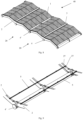
- Figure 1a and 2a shows an overview of a first embodiment of a solar support module 20 with solar panels 1 attached.
- Figure 1a and 2a shows as an example four panel arrays, each containing six solar panels.
- Figure 1b and 2b shows the same solar support modules as in figure 1a and 2a without the solar panels 1.
- Figure 1a-b shows the solar support module 20 in perspective view and figure 2a-b shows the solar support module viewed from above.
- the solar support module 20 has three main components; buoyancy elements 4, beam elements 2 and rib elements 5.
- the beam elements 2 are connecting the buoyancy elements 4 and the rib elements 5, together.
- the solar support modules 20 are designed to receive a plurality of solar panels 1 that are to be mounted on the upper surface of the solar support module 20.
- the solar support module 20 has at least two beam elements 2.
- figure 1a-1b and 2a-2b there are arranged three beam elements 2a, 2b, 2c.
- the beam elements are referred to as 2 in the figures illustrating only one beam element, since the beam elements are equal in shape.
- the beam elements 2a, 2b, 2c are arranged in parallel or substantially parallel to each other. They are also spaced apart as indicated in the figures.
- beam elements 2 may be possible, for instance only two beam elements 2a, 2c defining the outer edges of the solar support module 20. More than three beam elements 2a, 2b, 2c are also possible embodiments of the invention. The space between the beam elements 2a, 2b, 2c may also vary in different designs of the solar support module 20.
- Each beam element 2 having an elevated shape between the buoyancy elements 4 to reduce weight, facilitate the movement of the waves beneath the solar support module 20 and reduce the overall movement of the solar support module when installed at the water surface.
- Figure 1b further indicates that the each of the beam elements 2a, 2b, 2c is a U beam.
- the U-beam is arranged sideways such that flanges 27 of the U-beam extends in the horizontally direction, ie in a plane perpendicular to the plane of the beam element 2. This will be further disclosed.
- the solar support module 20 of figure 1a-1b and 2a-2b further comprises at least two buoyancy elements 4.
- buoyancy elements 4a, 4b, 4c there are disclosed three buoyancy elements 4a, 4b, 4c.
- buoyancy elements are referred to as 4 in the figures illustrating only one buoyancy element, since the buoyancy elements are equal in shape.
- the buoyancy elements 4a, 4b, 4c are arranged in parallel or substantially parallel to each other. They are also spaced apart as indicated in the figures.
- the buoyancy elements 4a, 4b, 4c are perpendicularly or substantially perpendicularly arranged with respect to the beam elements 2a, 2b, 2c.
- the assembly of beam elements 2a, 2b, 2c and buoyancy elements 4a thus forms a rectangular or a square frame of the solar support module 20 as shown in the figures.
- buoyancy elements 4 may be possible, for instance only two buoyancy elements 4a, 4c defining the outer edges of the solar support module 20. More than three buoyancy element 4a, 4b, 4c are also possible embodiments of the invention. The space between the buoyancy element 4a, 4b, 4c may also vary in different designs of the solar support module 20.
- the solar support module 20 further comprises a plurality of rib elements 5.
- the rib elements 5 are designed as elongated, rigid elements.
- the rib elements are arranged to form a girder at the top surface of the solar support module 20 to provide a further stiffening or rigidity of the solar support module 20.
- the rib elements 5 are extending between the outer beam elements 4a, 4c at the surface facing away from the buoyancy element 4a, 4b, 4c. This is shown in figure 1b and 2b .
- the rib elements 5 are arranged perpendicular or substantially perpendicular to the longitudinally direction of the beam elements 2a, 2b, 2c.
- the rib elements 5 are further arranged in parallel or substantially in parallel with the buoyancy members 4a, 4b, 4c in the longitudinal direction of the rib elements 5 and buoyancy members 4.
- the rib elements 5 are in the figure placed according to the panel configuration with minimum two rib elements 5 per panel array P ( figure 2a ). In other words, at least two rib elements 5 are supporting each solar panel 1.
- Other arrangement of the rib elements 5 are also possible embodiments of the invention.
- the rib elements 5 are arranged between the beam elements 2a, 2b, 2c and solar panels 1 when the solar panels 1 are mounted on the solar support module 20 as illustrated in figure 1a and 2a .
- the rib elements 5 are further arranged in a first recesses 26 of the beam element 2. This will be further described.
- the figure 1a-1b and fig. 2a-2b further shows a walkway 3 extending in the middle of the solar support module 20.
- the walkway 3 is further illustrated extending between the end beam elements 2a, 2c.
- FIGS. 1a-1b and 2a-2b are illustrating a single solar support module 20.
- a number of equal solar support modules 20 may be connected at all ends of the solar support module 20 to build a solar plant for a particular lake or seaside etc. This is shown in figure 8 and 9 .
- the beam elements 2a, 2b, 2c of the solar support module 20 are illustrated in further detail by the figure 3a-3b and 4a-4d .
- each beam element 2 is preferably made as one elongated piece.
- Each of the beam elements 2, rib elements 5 and the buoyancy elements 4 have a rigid structure.
- the assembly of the different elements 2, 4, 5 together in the grid structure provides an improved rigid structure that also provides an improved stability on the water surface.
- the second recesss 25a, 25b, 25c are adapted to receive the buoyancy elements 4a, 4b, 4c, respectively.
- the second recesses 25a, 25b, 25c do not need to have a semicircle shape. However, it is preferable that the second recesses 25a, 25b, 25c have a congruent shape as the buoyancy element 4 , to facilitate the connection with the buoyancy element 4.
- the respective second recess 25 have a shape so that the recesses mates with less than half of a cross-sectional surface of the buoyancy element 4.
- this means the second recess 25 is formed as a less than half circle, ie the circle is less than 180 degree. This provides an easy and rigid connection between buoyance element 4 and the beam element 2.
- the number of second recesses 25a, 25b, 25c in each beam element 2 corresponds with the number of buoyancy elements 4 required in the solar support module 20.
- the figures 4a and 4b shows the second recess 25a, 25b, 25c (also named 25) in one single beam element 2 according to an embodiment of the invention, in greater detail.
- the beam element 2a, 2b, 2c is further made with at least one lifted or elevated portion 21, as shown in the figure 3a-b, 4a and in greater detail in figure 4c .
- the lifted portion 21 is defined as the highest point on a vertex 21 in one single beam element 2a, 2b, 2c.
- the vertex 21 thus divides the beam element 2 in at least two portions; a first beam portion 22 and a second beam portion 23.
- the first beam portion 22, the second beam portion 23 and the vertex 21 constitute an angled portion 24.
- the beam element 2 as shown in the embodiment of the figure have two angled portions 24. However, only one, or more than one angled portion 24 may be possible embodiments of the invention.
- the respective angled portions 24 is preferably equal so that the lifted portions 21 are equal throughout a single beam element 2.
- the angled portions 24 may also be different throughout the single beam element 2.
- Both the first beam portion 22 and the second beam portion 23 have an angle distance ⁇ 1 , ⁇ 2 to a horizontal plane A extending through the center B of the buoyancy elements 4a, 4b, 4c.
- the angled distance ⁇ 1 , ⁇ 2 may be between 10-45°.
- a more preferred angled ⁇ 1 , ⁇ 2 distance may be between 10-25°.
- the indicated range is however not limiting for the invention, other angle distances ⁇ 1 , ⁇ 2 may also be possible.
- the angled distances ⁇ 1 , ⁇ 2 is preferably equal for both the first and second beam portion 22, 23.
- the angled distance ⁇ 1 and the angled distance ⁇ 2 may however also be different for the first and second beam portions 22, 23, respectively.
- the beam elements 2 that are to be used in the same solar support module 20 must however have corresponding angled portions 24 so that they follow the substantially the same curvature throughout the longitudinal direction of the beam element 2.
- the beam element(s) 2 may be produced with a specific angled distance optimized for the sun radiation/receiving of energy.
- a further advantage of different angles is that the floating solar modules may to adapt to different wave characteristics.
- the first beam portion 22 and the second beam portion 23 is extending in opposite directions upwardly between two adjacent buoyancy elements 4a and 4b or 4b and 4c. In the embodiment disclosed in the figures, this results in that there are two equal lifted portions 21 defined respectively by a pair of first and second beam portions 22, 23.
- the respective beam element 2 further comprises a plurality of first recesses 26 disposed on the surface of the beam element 2 facing away from the second recess(es) 25.
- the first recesses 26 are adapted to respectively receive the rib elements 5 and are thus having a matching shape as the rib elements 5, ie a U-formed shape.
- the first recesses 26 may be equally disposed in the longitudinally direction for the beam element 2.
- the first recesses 26 may also be arranged with different spaces between the first recesses 26 in a single beam element 2.
- first recesses 26 There must however be two first recesses 26 arranged in each of the first and second beam portions 22, 23 as indicated in the figure 4a .
- the first recesses 26 of the beam elements 2 in one solar support module 20 are also arranged so that the rib elements 5 received in the first recesses 26 are parallel.
- the first recesses 26 are thus arranged so that the rib elements 5 arranged in the first recesses 26 of the beam elements 2 forms a grid where beam elements 2 extending in a first longitudinal direction and the rib elements 5 extending in a second longitudinal direction that is perpendicular to the first direction.
- the pair of first recesses 26 arranged in a beam portion 22, 23 must also be arranged at different elevation as indicated in the figures 3a-b, 4a .
- the pair of rib elements 5 arranged in a beam portion 22, 23 also are also arranged at different elevation. This provides a stronger structure as the grid structure is formed by different planes. This further provides an improved torsional stiffness for the solar support module.
- first recesses 26 in each beam element 2 there are disclosed 10 first recesses 26 in each beam element 2 in the illustrated embodiment of the figures. This is only for exemplary purpose. More than 10 or less than 10 first recesses 26 and rib elements 5 are also possible embodiments of the invention.
- the first recesses 26 may be formed so that one of the edges 14, 15 of the first recess 26 is higher than the other edge 16. This is clear from figure 4b . In the figures, and especially figure 4b and figure 4b, 4c , it is indicated that the edge 15 facing the free end of the beam element 2' and the elevated portion 21 of the beam element 2 are higher that the edges 16 facing the middle of the beam portions 22, 23. This provides a support for the panel on the higher edge 16. It further provides some air and prevents unintentional contact areas between the solar panel 1 and the surface of the beam 2 in the middle portion of the beam portion 22, 23.
- the material of the beam element 2 is preferably materials with high strength/weight ratio. This may be a composite material, such as Glass Reinforced Polyester (GRP). Other material maybe Aluminium.
- GRP Glass Reinforced Polyester
- the GRP material has the advantage that it is not degraded by water.
- the material is also lightweight in comparison with the strength of the material and may also be tailored to the specific need.
- the beam element 2 further comprises end stoppers 12, 13.
- the end stoppers 12, 13 may be seen in all of the figure 1a-4c but are illustrated in detail in figure 4a and 4b .
- a first end stopper 13 is arranged.
- the first end stopper 13 is arranged near the free end of the beam element 2' as shown in figure 4b .
- the first end stopper 13 may be designed as an end wall.
- Each of the panels 1 to be mounted in the first panel array P is adapted to bear against the first end stopper 13. This provides a simplified method for arranging the panels 1 in the solar support module 20.
- a similar end stopper 12 is arranged at the opposite free end of the beam element 2' for aligning the panel array P at this end.
- Figures 3a-4a shows a similar end stopper, referred to as a second end stopper 12, arranged in the middle portion of the beam element 2.
- the second end stopper 12 is arranged beneath the walkway 3 and is arranged to support and align the solar panel array P arranged at both sides of the middle portion of the beam element 2.
- the positioning of the second end stopper 12 corresponds with the part or parts or the beam elements 2 that is not elevated and where an additional buoyancy member or members 4b is attached.
- end stoppers 12, 13 are arranged at non elevated portions of the respective beam element 2.
- the first and second end stopper 12, 13 thus provides a directional measurement for the solar panel arrays P arranged near the end stoppers 12, 13 at both sides of the first and second beam portions 22, 23.
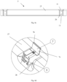
- Figure 4d discloses the beam element 2, perspective view. The figure shows clearly the U-shape of the beam 2.
- the beam element has a flange 27 extending from a main part of the beam element 29 along the entire circumference of the beam element 2.
- the beam element will thus have flanges 27 extending perpendicularly from the main part of the beam element 29. This provides an improved stability for the beam element 2.
- the figure 4d also indicates holes 28 adapted to correspond with holes in a bracket 30 to secure the buoyancy element 4 in the second recess 25.
- the design of the beam element 2 further provides an improved stability in all connections between the beam element 2 and other elements.
- Other elements may for instance be the buoyance element 4 and the rib element 5.
- FIG. 4e illustrates the U- shape in detail.
- the beam element 2 has a main part 29 and flanges 27 extending on the top part and bottom part of the beam element 2.
- the flanges 27 is extending horizontally to make use of the flanges for stability purposes and increase the contact surface between the beam element 2 and the connecting elements; rib elements 5 and buoyancy elements 4.
- the main part 29 thus also have some defined length which also increases the stability and robustness of the structure.
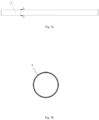
- FIG. 5a is illustrating the buoyancy element 4 isolated.
- the buoyancy element 4 is disclosed as a cylinder shaped, elongate element. However other shapes are possible embodiments of the invention.
- the buoyancy element 4 is intended to maintain the floating ability of the solar support module 20.
- the total number of buoyancy elements 4 must thus have enough capacity to keep the solar support module 20 with several solar panels 1, floating.
- the buoyancy element 4 is further made of a material that provides a rigid part of the solar support module 20.
- Preferable materials may be Polyethylene or other thermoplastic materials.
- the arrangement of the buoyancy elements 4 in the solar support module 20 further provides an improved movement on the water surface with respect to waves etc. There is a space between the buoyancy elements 4 or between the modules 20 such that the waves may move without any/less hindrance.
- the buoyancy elements 4 thus provides both buoyancy and rigidity at the same time.
- Figure 5b shows the buoyancy element 4 viewed from the behind.
- the buoyancy element 4 further has a shape so that it may easily fit into the shape of the second recess(s) 25 in the beam element 2.
- the shape shown in figure 5b is circular.
- the buoyancy element 4 fitted in the second recess 25 provides a further stability for the connection.
- the second recess 25 facilitates that the buoyancy element 4 are prevented from moving in relation to the beam element, when connected to the beam element 2.
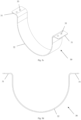
- Figure 5c and 5d is illustrating a bracket 30 for securing the buoyancy element 4 to the beam element 2.
- the buoyancy element 4 is resting in the bracket 30 and further attached on both ends at each side of the semi-circled second recess 25 in the beam element 2.
- the bracket 30 have a flange portion 31 at each side of the bow shape part 32 for connecting to the beam element 2 and facilitate the attachment between the beam element 2 and the bracket 30.
- brackets 30 to each beam elements 2a, 2b, 2c. These are fastening each beam elements to each buoyancy element 4. This provides a total of nine brackets 30 attaching three buoyancy elements 4a, 4b, 4c to the three beam elements 2a, 2b, 2c.
- the flange portion 31 may be attached to the beam element 2 through bolt and lock nut (not shown) in a per se known way.
- the buoyancy element 4 may however be attached to the beam element(s) 2 in other ways than through the bracket(s) 30. Other options are also possible embodiments of the invention.
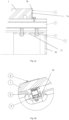
- Figure 6a- 6e are illustrating the rib element(s) 5 and the connection to the beam element(s) 2 in detail.
- the rib element 5 are arranged in the first recesses 26 as described above.
- the rib elements may be secured to the beam element 2 by a fastening mechanism, such as a bolt 9.
- the fastening mechanism 9 is per se known.
- the fastening mechanism 9 is shown in detail in figure 6a and 6b , while the figure 6c shows through holes 11 in the beam element 2 to receive the fastening mechanism 9.
- Both figure 6a and 6c shows the flange 27 of the beam element 2.
- the U-shaped beam with flange provides a fastening of the rib element 5 to the beam element 2 through two fastening mechanism 9. This provides rigid connection and increased stability for the solar support module 20.
- Figure 6c further illustrated the flange 27 size of the U-shaped beam element 2.
- the rib element 5 further comprises a solar panel lock 7. There is arranged a solar panel lock 7 at the end of each rib element 5.
- the solar panel lock 7 is arranged at the surface adapted to receive the solar panel 1.
- the solar panel lock 7 is adapted to attach the solar panel 1 to the rib element 5 and thus also attach the solar panel 1 to the solar support module 20. This may be performed in a number of different ways, but in the illustrated embodiment the solar panel lock 7 is designed as a slidable lock that is adapted to be moved towards an edge of the solar panel 1 to secure the panel 1 to the rib element 5.
- the solar panel lock 7 further has a vertical surface 7a with a horizontally arranged end hook 7b. The vertically surface 7a and the end hook 7b is shaped to match the height of the solar panel 1 to fasten the panel 1 to the solar support module 20. This is illustrated in detail in figure 6a and 6d .
- the material of the rib elements 5 may preferable be a high strength/weight ratio material, such as GRP, aluminum. Other corrosion resistant materials may however also be possible materials.
- Figure 7 is illustrating a spacer 6. There are arranged a number of spacers 6 between the solar panels 1. The spacers 6 are fixed onto the respective rib elements 5. This is also illustrated in figure 1a-2b . The figure 6b is also indicating the spacer 6 at the top of the solar panels 1 in further detail.
- the panel 1 When mounting a solar panel 1 onto the solar support module 20 at one of the ends along the outer beam elements 2a, 2c, the panel 1 is thus held in place by two solar panel lock 7 at one side of the panel 1 and two spacers 6 at the opposite side of the panel 1.
- the solar panels 1 When mounting a solar panel 1 in the middle of the solar support module 20, the solar panels 1 are held in place by spacers 6 at both sides of the solar panel 1.
- the spacer 6 is known per se.
- the solar panel 1 may also be arranged with a differently designed spacer, all of these being embodiments of the invention.
- the mounting of the individual solar support module 20 will be described further in the following:
- the respective elements, such as the buoyancy elements 4, beam elements 2, rib elements 5, that is required for an assembled solar support module 20 are transported to the location or site in separate pieces.
- the solar panels 1 are also transported individually to the site.
- the site may for instance be the shore next to the lake, pond, reservoir etc. where solar plant is intended to be used.
- a typical weight of the single elements to be assembled are 50 kg or less so that each part may easily be lifted and assembled manually.
- the buoyancy elements 4 are arranged in the predefined second recesses 25 in the beam elements 2 and attached to each beam element 2 through the bracket 30 or other fastening arrangements.
- the rib elements 5 are further arranged in the first recesses 26 at the top of the beam elements 2.
- the assembled arrangement is now forming one floating solar support module 20 as shown in fig. 1a-1b and 2a-2b .
- a plurality of solar panels may be arranged on top of the solar support module 20 through the solar panel and stopper 7 as describe above.
- solar support modules 20 may be assembled together forming the solar plant, as shown in figure 8 ). There may also be arranged walkways between two adjacent support modules 20 as illustrated in the figure. This will ease the access to the solar power plant.
- the floating solar support module 20 is arranged so that the contact through the entire bottom part of the entire solar support module 20 is avoided.
- entire square or rectangular part of the module is in contact with the water surface to provide a rigid structure.
- rib elements 5 that are attached to the solar panels 1 the solar support module 20 in a way such that the rib elements 5 along with solar panels 1 act as a rigid or strutting element to further increase the rigidity of the structure.
- the beam elements 2 further allow water to move freely underneath the solar panels to reduce excess movement.
- FIG 8 illustrates several floating solar power plant support modules 20 assembled into a solar power plant 40.
- the figure shows two solar support modules 20 interconnected through a common buoyancy element 4'.
- FIG 9 shows in detail the connection between two adjacent floating solar power plant support modules 20.
- the end buoyance element of solar support module becomes a common buoyancy element 4' for the beam elements 2 of both solar support modules 20.
- the beam elements are connected to the common buoyancy element 4' in the same way as described above with arranging the buoyancy element 4' in the second depression and securing the parts together.
Landscapes
- Engineering & Computer Science (AREA)
- Chemical & Material Sciences (AREA)
- Mechanical Engineering (AREA)
- Combustion & Propulsion (AREA)
- Physics & Mathematics (AREA)
- Sustainable Energy (AREA)
- Thermal Sciences (AREA)
- Sustainable Development (AREA)
- Life Sciences & Earth Sciences (AREA)
- General Engineering & Computer Science (AREA)
- Ocean & Marine Engineering (AREA)
- Architecture (AREA)
- Civil Engineering (AREA)
- Structural Engineering (AREA)
- Fluid Mechanics (AREA)
- Photovoltaic Devices (AREA)
Description
- The present invention relates to a support for a solar system. More particular the invention relates to a modular support for solar panels floating on the water surface. The invention also relates to a method for assembling the floating solar support module at site and a solar plant assembled from a number of floating solar support modules.
- Solar power will be an important energy source in the future.
- Today about 25% of the world power production comes from renewable energy sources. In the future, worldwide energy demand is expected to grow substantially, and this energy will mainly be covered by renewable energy, like solar and wind power.
- The predictions, together with the decrease of fossil fuel as an energy source, have stimulated a rapid growth in the development of renewable energy.
- Wind farms, hydroelectric power plants, thermal power stations, and solar power plants all traditionally need a certain area of land, which is costly and can negatively affect the environment The development of solar plants that are installed at the water surface, in lakes, ponds, reservoirs or other suitable sea or water surface is beneficial in that it reduces the need for land area. It is also beneficial in that the water provides a cooling of the solar plant. This results in an increased efficiency of the solar cells and thus an overall increased efficiency of the plant.
-
WO2019/122712 discloses a modular assembly for a floating solar power plant. The module comprises a molded construction which makes up the floating element. Each molded construction is filled with air to achieve the required buoyancy and the module is adapted to receive one single solar panel. Several modules may then be connected together to form an interconnected plant. The molded construction module has a design that is disadvantageous when exposed to wave movements from the water. A large portion of the plant according to the WO-publication will rest against the water surface. When the construction is moved by a wave, this movement will be transmitted to the whole connected plant and the plant will be subjected to excessive movement. There is also a need for a large volume to transport the modules to the site before installation. -
WO2012076007 relates to a floating frame for mounting at least one solar collector. The frame comprises two spaced apart floating elements and multiple bows extending between two spaced apart floats. Each bows are in the ends bent around the floating elements. The publication is designed for areas that are protected from wind and waves as the frame has a fragile structure that would not withstand large waves etc. The publication further fails to disclose an easy assembly of the individual modules and several modules put together.CN110277954 ,CN10904748 ,US2008029148 shows technical background to the invention. - The non-patent literature document " Design and installation of floating type photovoltaic energy generation system using FRP members", Young-Geun Lee, vol. 108, 1 October 2014 (2014-10-01), pages 13-27, discloses a floating solar power plant support module comprising a structural system supporting PV panels, said structural system being fixed on two elongate buoyancy elements.
-
Document EP 2 299 499 A1 discloses a floating solar power plant support module that comprises two elongate buoyancy elements, said two elongate buoyancy elements being parallelly arranged. Two beam elements are connected to the elongate buoyancy elements, said two beam elements being perpendicularly arranged with respect to the buoyancy elements. Elongate rib elements are attached to the beam elements. A first bracket and a second bracket are fixed on the beam elements and applied over the buoyancy elements. - The present invention has the following advantages over the prior art:
- The invention is based on separate elements which provides low volume and low weight when transported. This makes it easier to transport the solar plant since the elements are able to be transported in parts by a small or compact transport carrier to the site, instead of the whole support module.
- Such installations are often performed in areas without any access to cranes and other advanced lifting appliances. The low weight of the elements thus provides a simple, assembly adapted to be handled manually by hand.
- The invention further provides a high degree of flexibility with respect to the size of the panels, number of panels and the angle of the solar panels in the installation. The angle of the solar panels is important as the solar panels are tilted and adjusted towards an optimal angle of irradiance from the sun.
- The assembled solar support module comprises several solar panels. Several solar support modules can be connected to form a large solar plant. The assembly of the modules provides an easy adaptable and flexible solar plant.
- The invention further provides a stable device. Stability is important for maintenance purposes, but more importantly, stability maintain the correct angle to optimize solar energy output for the plant.
- Stability also enhances the resistance towards environmental forces (wind, waves) since the unit has a larger area/footprint. This means that the invention may be arranged in harsh environment and may withstand the forces acting on the structure. The arrangement of the different parts of the structure also facilities the robustness of the invention.
- The module of the invention is further designed to provide a volume or a separate space underneath the module. This results in less movement of the construction which again provides less fatigue and increased operating time.
- Further and other advantages will be apparent in the following description of the invention.
- The invention relates to a floating solar power plant support module comprising at least two elongate buoyancy elements, said the at least two buoyancy elements being substantially parallelly arranged, at least two beam elements connected to the elongate buoyancy elements, said the at least two beam elements being substantially perpendicularly arranged with respect to the elongate buoyancy elements, said the at least two beam elements having each a lifted or vertex portion arising from an angled portion of the beam situated between two adjacent buoyancy elements in order to reduce movement caused by waves when installed at the water surface.
- The at least two beam elements being respectively formed as a U-shaped beam element with flanges, said respective beam elements having at least two second recesses adapted to respectively receive at least a portion of the buoyancy element, and at least two first recesses, said first and second recesses are formed in the surface of the flanges,
the solar support module further comprises at least two elongate rib elements arranged respectively in the first recesses of the at least two beam elements, said the at least two rib elements being substantially perpendicularly arranged with respect to the at least two beam elements. The first recesses and the second recesses are arranged in opposite flanges of the U-shaped beam elements. - Preferably, each point of the flanges extending in a direction parallelly arranged to a plane extending through the centre of the buoyancy elements.
- Preferably, respectively the at least two elongate buoyancy elements, the at least two beam elements and at least two elongate rib elements, respectively being arranged spaced apart.
- Preferably, said angled portion comprising a first beam portion and a second beam portion, said first and second beam portion having each an angled distance from a horizontal plane extending through the center of the buoyancy elements.
- Preferably, the angled distance of said first and second beam portion being equal or the angled distance of the first beam portion being different from the angled distance of the second beam portion.
- Preferably, the angled distance is between 10-45°.
- Preferably, the support module having a plurality of rib elements distributed separately in the first recesses throughout the length of the respective beam elements.
- Preferably, the second recesses in the beam element being semi-circular to mate with a circular buoyance element.
- Preferably, the support module further comprises a bracket for securing the buoyancy element to the beam element.
- Preferably, the solar support module further comprises a spacer and fastening mechanism for securing a solar panel to the solar support module.
- Preferably, each beam element comprises end stoppers arranged at non-elevated portions of the beam element in order to facilitate the positioning of the panel.
- The invention further relates to a floating solar power plant comprising a plurality of interconnected floating solar power plant support modules.
- One of the at least two buoyancy elements of two adjacent support modules is a common buoyancy element connected to the beam elements from the adjacently arranged solar power plant support modules.
- Preferably the floating solar plant further comprises a walkway separating two adjacent solar support modules.
- The invention further relates to a method for assembling a floating solar power plant and/or the modules of the solar power plant at a remote location where the floating solar power plant is to be installed or used, comprising the following steps;
- transporting the individual elements separately to the remote location, connecting the at least two beam elements and the at least two elongate buoyancy elements perpendicularly together to form a frame, by arranging the buoyancy element in the second recess of the beam element and securing the buoyance element to the beam element,
- securing at least two ribs substantially perpendicularly at the first recesses of the beam elements.
- Preferably, the method comprises a fastening of the buoyancy element through a bracket, such as a bow shaped element.
- Preferably, the method further comprises the step of connecting the solar support modules through a common buoyancy element into the floating solar power plant.
- The invention describes also to a method for assembling of the floating solar power plant support module. The method comprises the following steps of connecting the at least two beams and the at least two elongate buoyancy elements perpendicularly together to form a frame.
- Preferably, the method further comprising the step of extending at least two ribs perpendicularly between the beams defining the outer edges of the frame at the surface of the beams facing away from the buoyancy elements.
-
-
Figure 1a shows a perspective view of a first embodiment of a solar support module with solar panels attached. -
Figure 1b hows a perspective view of the first embodiment of the solar support module without solar panels. -
Figure 2a shows the solar support module fromfigure 1a , viewed from above. -
Figure 2b shows the solar support module fromfigure 1b , viewed from above. -
Figure 3a shows the solar support module fromfigure 1a with solar panels, viewed from the side. -
Figure 3b shows the solar support module fromfigure 1b without solar panels, viewed from the side. -
Figure 4a shows the embodiment of the beam element fromfig. 1a , in isolation, viewed from the side. -
Figure 4b shows a detail view of a free end of the beam element fromfigure 4a . -
Figure 4c shows a detail view of a vertex on the beam element fromfigure 4a . -
Figure 4d shows a perspective view of the beam element, to illustrate the U-shape of the beam element and the flanges -
Figure 4e shows a cross sectional view of the beam element with U-shaped profile. -
Figure 5a shows the embodiment of the buoyancy element fromfig. 1a , in isolation, viewed from above. -
Figure 5b shows the buoyancy element fromfig. 5a , viewed from behind. -
Figure 5c shows an embodiment of a bracket for attaching the buoyancy element to the beam element, perspective view. -
Figure 5d shows the embodiment of the bracket fromfig. 5c , viewed from the side. -
Figure 6a shows a detailed view of a rib element attached between the beam element and the solar panel, viewed from behind. -
Figure 6b shows a detailed view of the rib element attached between the beam element and the solar panel, viewed from the side. -
Fig. 6c shows a detailed view of the beam element with first recesses adapted to receive the rib elements. -
Figure 6d shows a detailed view of the fastening mechanism for attaching the solar panel to the solar support module. -
Figure 6e shows a sectional view of the first beam portion with ribs and solar panels attached. -
Figure 7 shows a spacer and fastening mechanism for use between solar panels. -
Figure 8 illustrates several floating solar power plant support modules assembled into a solar power plant. -
Figure 9 shows the connection between two adjacent floating solar power plant support modules, in detail. - The term "floating solar power plant support module" or "floating solar support module" in short, is to be interpreted an assembly of a number of beam elements, a number of buoyancy elements and a number of rib elements into a rectangular or square frame as illustrated in the
figure 1b ,2b . This solar support module is adapted to receive a number of solar panels mounted at the top surface of the solar support module as illustrated infig. 1a, 1b . - The term "solar power plant" or "solar plant" in short, is to be interpreted as an assembly of a number of floating solar support modules into a complete structure for the actual pond, lake, reservoir etc.
- The term "solar panel" is to be interpreted as the elements that absorbs sunlight as a source of energy to generate direct current electricity. The solar panels are most commonly photovoltaic solar panels. This type of panel is however not limiting for the invention.
- The term "panel array" is to be interpreted as a row of solar panels extending subsequently from one outer beam element to the other outer beam element.
- The term "middle" in relation to the beam element, buoyancy element, end stopper etc do not refer to an actual middle position of the solar support module. The terms rather refer to a position within the frame where the beam element is not elevated. This may be in center points of the structure or is may be offset of the center. This is defined by the number of elevations of the beam elements and the number of buoyancy elements attached to the beam elements.
-
Figure 1a and2a shows an overview of a first embodiment of asolar support module 20 withsolar panels 1 attached. -
Figure 1a and2a shows as an example four panel arrays, each containing six solar panels. -
Figure 1b and2b shows the same solar support modules as infigure 1a and2a without thesolar panels 1. -
Figure 1a-b shows thesolar support module 20 in perspective view andfigure 2a-b shows the solar support module viewed from above. - The
solar support module 20 has three main components;buoyancy elements 4,beam elements 2 andrib elements 5. Thebeam elements 2 are connecting thebuoyancy elements 4 and therib elements 5, together. The components will be further described in the following and in connection with the figures. - The
solar support modules 20 are designed to receive a plurality ofsolar panels 1 that are to be mounted on the upper surface of thesolar support module 20. - The
solar support module 20 has at least twobeam elements 2. Infigure 1a-1b and2a-2b there are arranged threebeam elements end beam elements solar support module 20 at each side of themodule 20. In addition, there is arranged amiddle beam element 2b approximately in the middle between theend beam elements beam elements - Other arrangements of the
beam elements 2 may be possible, for instance only twobeam elements solar support module 20. More than threebeam elements beam elements solar support module 20. - Each
beam element 2 having an elevated shape between thebuoyancy elements 4 to reduce weight, facilitate the movement of the waves beneath thesolar support module 20 and reduce the overall movement of the solar support module when installed at the water surface. -
Figure 1b further indicates that the each of thebeam elements flanges 27 of the U-beam extends in the horizontally direction, ie in a plane perpendicular to the plane of thebeam element 2. This will be further disclosed. - The
solar support module 20 offigure 1a-1b and2a-2b further comprises at least twobuoyancy elements 4. In thefigure 1a-1b and2a-2b , there are disclosed threebuoyancy elements end buoyancy elements solar support module 20 at each side of themodule 20. In addition, there is arranged amiddle buoyancy element 4b in the middle between theend buoyancy elements - For simplicity, the buoyancy elements are referred to as 4 in the figures illustrating only one buoyancy element, since the buoyancy elements are equal in shape.
- The
buoyancy elements buoyancy elements beam elements beam elements buoyancy elements 4a, thus forms a rectangular or a square frame of thesolar support module 20 as shown in the figures. - Other arrangements of the
buoyancy elements 4 may be possible, for instance only twobuoyancy elements solar support module 20. More than threebuoyancy element buoyancy element solar support module 20. - The
solar support module 20 further comprises a plurality ofrib elements 5. Therib elements 5 are designed as elongated, rigid elements. The rib elements are arranged to form a girder at the top surface of thesolar support module 20 to provide a further stiffening or rigidity of thesolar support module 20. Therib elements 5 are extending between theouter beam elements buoyancy element figure 1b and2b . Therib elements 5 are arranged perpendicular or substantially perpendicular to the longitudinally direction of thebeam elements rib elements 5 are further arranged in parallel or substantially in parallel with thebuoyancy members rib elements 5 andbuoyancy members 4. Therib elements 5 are in the figure placed according to the panel configuration with minimum tworib elements 5 per panel array P (figure 2a ). In other words, at least tworib elements 5 are supporting eachsolar panel 1. Other arrangement of therib elements 5 are also possible embodiments of the invention. - The
rib elements 5 are arranged between thebeam elements solar panels 1 when thesolar panels 1 are mounted on thesolar support module 20 as illustrated infigure 1a and2a . Therib elements 5 are further arranged in a first recesses 26 of thebeam element 2. This will be further described. - The
figure 1a-1b andfig. 2a-2b further shows awalkway 3 extending in the middle of thesolar support module 20. Thewalkway 3 is further illustrated extending between theend beam elements - It is to be noted that the
figures 1a-1b and2a-2b are illustrating a singlesolar support module 20. A number of equalsolar support modules 20 may be connected at all ends of thesolar support module 20 to build a solar plant for a particular lake or seaside etc. This is shown infigure 8 and 9 . - The
beam elements solar support module 20 are illustrated in further detail by thefigure 3a-3b and4a-4d . - The individual features of the
solar support module 20 will be described further in relation to thefigures 3-7 . - As indicated in
figure 3a-3b and 4a the eachbeam element 2 is preferably made as one elongated piece. - Each of the
beam elements 2,rib elements 5 and thebuoyancy elements 4 have a rigid structure. The assembly of thedifferent elements - At the surface of the
beam element 2 facing the water surface there are arranged semi-circledsecond recesses fig. 4b ). Thesecond recesss buoyancy elements second recesses second recesses buoyancy element 4 , to facilitate the connection with thebuoyancy element 4. - It is further preferably that the respective
second recess 25 have a shape so that the recesses mates with less than half of a cross-sectional surface of thebuoyancy element 4. For abuoyancy element 4 as illustrated infig. 4b , this means thesecond recess 25 is formed as a less than half circle, ie the circle is less than 180 degree. This provides an easy and rigid connection betweenbuoyance element 4 and thebeam element 2. - The number of
second recesses beam element 2 corresponds with the number ofbuoyancy elements 4 required in thesolar support module 20. Thefigures 4a and4b shows thesecond recess single beam element 2 according to an embodiment of the invention, in greater detail. - The
beam element elevated portion 21, as shown in thefigure 3a-b, 4a and in greater detail infigure 4c . The liftedportion 21 is defined as the highest point on avertex 21 in onesingle beam element vertex 21 thus divides thebeam element 2 in at least two portions; afirst beam portion 22 and asecond beam portion 23. Thefirst beam portion 22, thesecond beam portion 23 and thevertex 21 constitute anangled portion 24. Thebeam element 2 as shown in the embodiment of the figure have twoangled portions 24. However, only one, or more than oneangled portion 24 may be possible embodiments of the invention. The respectiveangled portions 24 is preferably equal so that the liftedportions 21 are equal throughout asingle beam element 2. Theangled portions 24 may also be different throughout thesingle beam element 2. - Both the
first beam portion 22 and thesecond beam portion 23 have an angle distance α1, α2 to a horizontal plane A extending through the center B of thebuoyancy elements second beam portion second beam portions - The
beam elements 2 that are to be used in the samesolar support module 20 must however have correspondingangled portions 24 so that they follow the substantially the same curvature throughout the longitudinal direction of thebeam element 2. - The beam element(s) 2 may be produced with a specific angled distance optimized for the sun radiation/receiving of energy.
- A further advantage of different angles is that the floating solar modules may to adapt to different wave characteristics.
- The
first beam portion 22 and thesecond beam portion 23 is extending in opposite directions upwardly between twoadjacent buoyancy elements portions 21 defined respectively by a pair of first andsecond beam portions - The
respective beam element 2 further comprises a plurality offirst recesses 26 disposed on the surface of thebeam element 2 facing away from the second recess(es) 25. The first recesses 26 are adapted to respectively receive therib elements 5 and are thus having a matching shape as therib elements 5, ie a U-formed shape. - The first recesses 26 may be equally disposed in the longitudinally direction for the
beam element 2. The first recesses 26 may also be arranged with different spaces between thefirst recesses 26 in asingle beam element 2. - There must however be two
first recesses 26 arranged in each of the first andsecond beam portions figure 4a . The first recesses 26 of thebeam elements 2 in onesolar support module 20 are also arranged so that therib elements 5 received in thefirst recesses 26 are parallel. The first recesses 26 are thus arranged so that therib elements 5 arranged in thefirst recesses 26 of thebeam elements 2 forms a grid wherebeam elements 2 extending in a first longitudinal direction and therib elements 5 extending in a second longitudinal direction that is perpendicular to the first direction. The pair offirst recesses 26 arranged in abeam portion figures 3a-b, 4a . since thefirst recesses 26 in eachbeam portions rib elements 5 arranged in abeam portion - There are disclosed 10
first recesses 26 in eachbeam element 2 in the illustrated embodiment of the figures. This is only for exemplary purpose. More than 10 or less than 10first recesses 26 andrib elements 5 are also possible embodiments of the invention. - The first recesses 26 may be formed so that one of the
edges first recess 26 is higher than theother edge 16. This is clear fromfigure 4b . In the figures, and especiallyfigure 4b and figure 4b, 4c , it is indicated that theedge 15 facing the free end of the beam element 2' and theelevated portion 21 of thebeam element 2 are higher that theedges 16 facing the middle of thebeam portions higher edge 16. It further provides some air and prevents unintentional contact areas between thesolar panel 1 and the surface of thebeam 2 in the middle portion of thebeam portion - It is the
rib elements 5 that mainly supports thepanels 1 when arranged on thesolar support module 20. - The material of the
beam element 2 is preferably materials with high strength/weight ratio. This may be a composite material, such as Glass Reinforced Polyester (GRP). Other material maybe Aluminium. The GRP material has the advantage that it is not degraded by water. The material is also lightweight in comparison with the strength of the material and may also be tailored to the specific need. - The
beam element 2 further comprisesend stoppers end stoppers figure 1a-4c but are illustrated in detail infigure 4a and4b . - In
figure 4b afirst end stopper 13 is arranged. Thefirst end stopper 13 is arranged near the free end of the beam element 2' as shown infigure 4b . Thefirst end stopper 13 may be designed as an end wall. Each of thepanels 1 to be mounted in the first panel array P is adapted to bear against thefirst end stopper 13. This provides a simplified method for arranging thepanels 1 in thesolar support module 20. Asimilar end stopper 12 is arranged at the opposite free end of the beam element 2' for aligning the panel array P at this end. -
Figures 3a-4a shows a similar end stopper, referred to as asecond end stopper 12, arranged in the middle portion of thebeam element 2. Thesecond end stopper 12 is arranged beneath thewalkway 3 and is arranged to support and align the solar panel array P arranged at both sides of the middle portion of thebeam element 2. The positioning of thesecond end stopper 12 corresponds with the part or parts or thebeam elements 2 that is not elevated and where an additional buoyancy member ormembers 4b is attached. - In general, the
end stoppers respective beam element 2. - The first and
second end stopper end stoppers second beam portions -
Figure 4d discloses thebeam element 2, perspective view. The figure shows clearly the U-shape of thebeam 2. The beam element has aflange 27 extending from a main part of thebeam element 29 along the entire circumference of thebeam element 2. The beam element will thus haveflanges 27 extending perpendicularly from the main part of thebeam element 29. This provides an improved stability for thebeam element 2. - The
figure 4d also indicatesholes 28 adapted to correspond with holes in abracket 30 to secure thebuoyancy element 4 in thesecond recess 25. - The design of the
beam element 2 further provides an improved stability in all connections between thebeam element 2 and other elements. Other elements may for instance be thebuoyance element 4 and therib element 5. -
Figure 4e illustrates the U- shape in detail. Thebeam element 2 has amain part 29 andflanges 27 extending on the top part and bottom part of thebeam element 2. Theflanges 27 is extending horizontally to make use of the flanges for stability purposes and increase the contact surface between thebeam element 2 and the connecting elements;rib elements 5 andbuoyancy elements 4. As indicated in the figure, there is some space between theflanges 27. Themain part 29 thus also have some defined length which also increases the stability and robustness of the structure. -
Figure 5a is illustrating thebuoyancy element 4 isolated. Thebuoyancy element 4 is disclosed as a cylinder shaped, elongate element. However other shapes are possible embodiments of the invention. - The
buoyancy element 4 is intended to maintain the floating ability of thesolar support module 20. The total number ofbuoyancy elements 4 must thus have enough capacity to keep thesolar support module 20 with severalsolar panels 1, floating. - The
buoyancy element 4 is further made of a material that provides a rigid part of thesolar support module 20. Preferable materials may be Polyethylene or other thermoplastic materials. - The arrangement of the
buoyancy elements 4 in thesolar support module 20 further provides an improved movement on the water surface with respect to waves etc. There is a space between thebuoyancy elements 4 or between themodules 20 such that the waves may move without any/less hindrance. - The
buoyancy elements 4 thus provides both buoyancy and rigidity at the same time. -
Figure 5b shows thebuoyancy element 4 viewed from the behind. - The
buoyancy element 4 further has a shape so that it may easily fit into the shape of the second recess(s) 25 in thebeam element 2. The shape shown infigure 5b is circular. Thebuoyancy element 4 fitted in thesecond recess 25 provides a further stability for the connection. Thesecond recess 25 facilitates that thebuoyancy element 4 are prevented from moving in relation to the beam element, when connected to thebeam element 2. -
Figure 5c and 5d is illustrating abracket 30 for securing thebuoyancy element 4 to thebeam element 2. Thebuoyancy element 4 is resting in thebracket 30 and further attached on both ends at each side of the semi-circledsecond recess 25 in thebeam element 2. Thebracket 30 have aflange portion 31 at each side of thebow shape part 32 for connecting to thebeam element 2 and facilitate the attachment between thebeam element 2 and thebracket 30. - There are further indicated through
holes 33 in theflange portion 31 for receiving fastening devices, such as bolts etc. There is arranged abracket 30 to each semi-circledsecond recess 25 of thebeam elements 2. - As an illustrating example, there are indicated three
brackets 30 to eachbeam elements buoyancy element 4. This provides a total of ninebrackets 30 attaching threebuoyancy elements beam elements flange portion 31 may be attached to thebeam element 2 through bolt and lock nut (not shown) in a per se known way. - The
buoyancy element 4 may however be attached to the beam element(s) 2 in other ways than through the bracket(s) 30. Other options are also possible embodiments of the invention. -
Figure 6a- 6e are illustrating the rib element(s) 5 and the connection to the beam element(s) 2 in detail. - The
rib element 5 are arranged in thefirst recesses 26 as described above. The rib elements may be secured to thebeam element 2 by a fastening mechanism, such as abolt 9. Thefastening mechanism 9 is per se known. Thefastening mechanism 9 is shown in detail infigure 6a and 6b , while thefigure 6c shows throughholes 11 in thebeam element 2 to receive thefastening mechanism 9. Bothfigure 6a and6c shows theflange 27 of thebeam element 2. As indicated infigure 6a the U-shaped beam with flange provides a fastening of therib element 5 to thebeam element 2 through twofastening mechanism 9. This provides rigid connection and increased stability for thesolar support module 20.Figure 6c further illustrated theflange 27 size of theU-shaped beam element 2. - The
rib element 5 further comprises asolar panel lock 7. There is arranged asolar panel lock 7 at the end of eachrib element 5. Thesolar panel lock 7 is arranged at the surface adapted to receive thesolar panel 1. Thesolar panel lock 7 is adapted to attach thesolar panel 1 to therib element 5 and thus also attach thesolar panel 1 to thesolar support module 20. This may be performed in a number of different ways, but in the illustrated embodiment thesolar panel lock 7 is designed as a slidable lock that is adapted to be moved towards an edge of thesolar panel 1 to secure thepanel 1 to therib element 5. Thesolar panel lock 7 further has avertical surface 7a with a horizontally arrangedend hook 7b. The vertically surface 7a and theend hook 7b is shaped to match the height of thesolar panel 1 to fasten thepanel 1 to thesolar support module 20. This is illustrated in detail infigure 6a and6d . - There are arranged one
solar panel lock 7 at the free end of eachrib element 5. This results in that asolar panel 1 is attached to thesolar support module 20 by two solar panel locks 7 arranged at two differently arrangedrib elements 5. - The material of the
rib elements 5 may preferable be a high strength/weight ratio material, such as GRP, aluminum. Other corrosion resistant materials may however also be possible materials. -
Figure 7 is illustrating aspacer 6. There are arranged a number ofspacers 6 between thesolar panels 1. Thespacers 6 are fixed onto therespective rib elements 5. This is also illustrated infigure 1a-2b . Thefigure 6b is also indicating thespacer 6 at the top of thesolar panels 1 in further detail. - When mounting a
solar panel 1 onto thesolar support module 20 at one of the ends along theouter beam elements panel 1 is thus held in place by twosolar panel lock 7 at one side of thepanel 1 and twospacers 6 at the opposite side of thepanel 1. When mounting asolar panel 1 in the middle of thesolar support module 20, thesolar panels 1 are held in place byspacers 6 at both sides of thesolar panel 1. Thespacer 6 is known per se. - The
solar panel 1 may also be arranged with a differently designed spacer, all of these being embodiments of the invention. - The mounting of the individual
solar support module 20 will be described further in the following:
The respective elements, such as thebuoyancy elements 4,beam elements 2,rib elements 5, that is required for an assembledsolar support module 20 are transported to the location or site in separate pieces. Thesolar panels 1 are also transported individually to the site. The site may for instance be the shore next to the lake, pond, reservoir etc. where solar plant is intended to be used. A typical weight of the single elements to be assembled are 50 kg or less so that each part may easily be lifted and assembled manually. - The
buoyancy elements 4 are arranged in the predefinedsecond recesses 25 in thebeam elements 2 and attached to eachbeam element 2 through thebracket 30 or other fastening arrangements. - The
rib elements 5 are further arranged in thefirst recesses 26 at the top of thebeam elements 2. The assembled arrangement is now forming one floatingsolar support module 20 as shown infig. 1a-1b and2a-2b . A plurality of solar panels may be arranged on top of thesolar support module 20 through the solar panel andstopper 7 as describe above. - Several
solar support modules 20 may be assembled together forming the solar plant, as shown infigure 8 ). There may also be arranged walkways between twoadjacent support modules 20 as illustrated in the figure. This will ease the access to the solar power plant. - The floating
solar support module 20 is arranged so that the contact through the entire bottom part of the entiresolar support module 20 is avoided. In commonly known solar support plant, entire square or rectangular part of the module is in contact with the water surface to provide a rigid structure. However, it is known to give a certain excessive movement when there are movement in the water surface. - In the solar support module according to the invention there are therefore
rib elements 5 that are attached to thesolar panels 1 thesolar support module 20 in a way such that therib elements 5 along withsolar panels 1 act as a rigid or strutting element to further increase the rigidity of the structure. Thebeam elements 2 further allow water to move freely underneath the solar panels to reduce excess movement. -
Figure 8 illustrates several floating solar powerplant support modules 20 assembled into asolar power plant 40. The figure shows twosolar support modules 20 interconnected through a common buoyancy element 4'. -
Figure 9 shows in detail the connection between two adjacent floating solar powerplant support modules 20. As illustrated in the figure, the end buoyance element of solar support module becomes a common buoyancy element 4' for thebeam elements 2 of bothsolar support modules 20. The beam elements are connected to the common buoyancy element 4' in the same way as described above with arranging the buoyancy element 4' in the second depression and securing the parts together. - The present invention has been described with reference to a preferred embodiment and some drawings for the sake of understanding only and it should be clear to persons skilled in the art that the present invention includes all legitimate modifications within the ambit of what has been described hereinbefore and claimed in the appended claims.
Claims (15)
- A floating solar power plant support module that comprises at least two elongate buoyancy elements (4a, 4b, 4c), said at least two elongate buoyancy elements (4a, 4b, 4c) being substantially parallelly arranged, at least two beam elements (2a, 2b, 2c) connected to the elongate buoyancy elements (4a, 4b, 4c), said at least two beam elements (2a, 2b, 2c) being substantially perpendicularly arranged with respect to the elongate buoyancy elements (4a, 4b, 4c), said at least two beam elements (2a, 2b, 2c) having each a vertex portion (21) arising from an angled portion (24) of the respective beam element (2a, 2b, 2c) situated between two adjacent buoyancy elements (4a, 4b ,4c), wherein the at least two beam elements (2a, 2b, 2c) are respectively formed as a U-shaped beam element (27, 29) with flanges (27), said respective beam elements (2a, 2b, 2c) having at least two second recesses (25) adapted to respectively receive at least a portion of the buoyancy element (4a, 4b, 4c), and at least two first recesses (26), said first and second recesses (25, 26) being formed in the surface of the flanges (27), the solar support module further comprises at least two elongate rib elements (5) arranged respectively in the first recesses (26) of the at least two beam elements (2a, 2b, 2c), said the at least two rib elements (5) being substantially perpendicularly arranged with respect to the at least two beam elements (2a, 2b, 2c), wherein the first recesses (26) and the second recesses (25) are arranged in opposite flanges (27) of the U-shaped beam elements.
- The floating solar power plant support module according to claim 1, wherein the flanges extend in a direction parallelly arranged to a plane (A) extending through the centre (B) of the buoyancy elements (4a, 4b, 4c).
- The floating solar power plant support module according to claim 1 or 2, wherein the at least two elongate buoyancy elements (4a, 4b, 4c), the at least two beams (2a, 2b, 2c) and at least two elongate rib elements (5) are respectively arranged spaced apart
- The floating solar power plant support module according to claim 1, 2 or 3, wherein said angled portion (24) comprises a first beam portion (22) and a second beam portion (23), said first and second beam portion (22, 23) having each an angled distance (α1, α2) from a horizontal plane (A) extending through the center (B) of the buoyancy elements (4a, 4b, 4c).
- The floating solar power plant support module according to claim 4, wherein the angled distance (α1, α2) of said first and second beam portion (22, 23) is equal or the angled distance (α1) of the first beam portion (22) is different from the angled distance (α2) of the second beam portion (23).
- The floating solar power plant support module according to any of the claims 2-5, wherein the angled distance (α1, α2) is between 10-45°.
- The floating solar power plant support module according to any of the claims 1-6, wherein the support module (20) has a plurality of rib elements (5) distributed separately in the first recesses (26) throughout the length of the respective beam elements (2a, 2b, 2c).
- The floating solar power plant support module according to any one of the claims 1-7, wherein the second recess (25) in the beam element (2a, 2b, 2c) is semi-circular to mate with a circular buoyance element (4a, 4b, 4c).
- The floating solar power plant support module according to any one of the claims 1-8, wherein the support module further comprises a bracket (30) for securing the buoyancy element (4a, 4b, 4c) to the beam element (2a, 2b, 2c).
- The floating solar power plant support module according to any one of the claims 1-9, wherein each beam element (2a, 2b, 2c) comprises end stoppers (12, 13) arranged at non-elevated portions of the beam element 2a, 2b, 2c) in order to facilitate the positioning of the panel (1).
- A floating solar power plant characterized in that said power plant comprises a plurality of interconnected floating solar power plant support modules (20) according to any of the claims 1-10, wherein one of the at least two buoyancy elements (4a, 4b, 4c) is a common buoyancy element (4') connected to the beam elements (2a, 2b, 2c) from two adjacently arranged solar power plant support modules (20).
- The floating solar power plant according to claim 11, wherein the solar power plant comprises a walkway (3).
- A method for assembling a floating solar power plant module according to any one of the claims 1-10 at a remote location where a floating solar power plant is to be installed, characterized in that the method comprises the following steps;- transporting the individual elements (2, 4, 5, 1) separately to the remote location,- connecting the at least two beam elements (2a, 2b, 2c) and the at least two elongate buoyancy elements (4a, 4b, 4c) substantially perpendicularly together to form a frame, by arranging the buoyancy element (4) in the second recess (25) of each beam element (2) and securing the buoyance element (4) to the beam element (2),- securing at least two ribs (5) substantially perpendicularly at the first recesses (26) of the beam elements (2).
- The method according to claim 13, wherein the method further comprises the step of fastening the buoyancy element through a bracket, such as a bow shaped element (30).
- The method according to claim 13 or 14, wherein the method further comprises the step of connecting the solar support modules through a common buoyancy element (4').
Applications Claiming Priority (2)
| Application Number | Priority Date | Filing Date | Title |
|---|---|---|---|
| NO20200103 | 2020-01-27 | ||
| PCT/EP2021/051856 WO2021151940A1 (en) | 2020-01-27 | 2021-01-27 | Floating solar support module |
Publications (2)
| Publication Number | Publication Date |
|---|---|
| EP4097842A1 EP4097842A1 (en) | 2022-12-07 |
| EP4097842B1 true EP4097842B1 (en) | 2024-10-30 |
Family
ID=74505206
Family Applications (1)
| Application Number | Title | Priority Date | Filing Date |
|---|---|---|---|
| EP21702904.0A Active EP4097842B1 (en) | 2020-01-27 | 2021-01-27 | Floating solar support module |
Country Status (2)
| Country | Link |
|---|---|
| EP (1) | EP4097842B1 (en) |
| WO (1) | WO2021151940A1 (en) |
Families Citing this family (1)
| Publication number | Priority date | Publication date | Assignee | Title |
|---|---|---|---|---|
| CN114872851A (en) * | 2022-05-16 | 2022-08-09 | 一道新能源科技(衢州)有限公司 | Offshore photovoltaic fabricated floating platform and manufacturing and assembling method |
Family Cites Families (5)
| Publication number | Priority date | Publication date | Assignee | Title |
|---|---|---|---|---|
| US20080029148A1 (en) | 2004-10-29 | 2008-02-07 | Thompson Daniel S | Floating support structure for a solar panel array |
| CH701870A2 (en) * | 2009-09-17 | 2011-03-31 | Tnc Consulting Ag | Floating photovoltaic arrangement. |
| DE102011009424A1 (en) | 2010-12-11 | 2012-06-14 | Christof Zosel | Frame for the floating attachment of at least one solar collector |
| FR3076125B1 (en) | 2017-12-22 | 2021-02-26 | Ciel Et Terre Int | MODULAR ASSEMBLY FOR FLOATING SOLAR POWER PLANT |
| CN110277954A (en) | 2019-07-22 | 2019-09-24 | 长江勘测规划设计研究有限责任公司 | Floating body multifunctional integrated water surface photovoltaic support system suitable for alpine regions |
-
2021
- 2021-01-27 EP EP21702904.0A patent/EP4097842B1/en active Active
- 2021-01-27 WO PCT/EP2021/051856 patent/WO2021151940A1/en not_active Ceased
Also Published As
| Publication number | Publication date |
|---|---|
| WO2021151940A1 (en) | 2021-08-05 |
| EP4097842A1 (en) | 2022-12-07 |
Similar Documents
| Publication | Publication Date | Title |
|---|---|---|
| US20130240025A1 (en) | Buoyant solar panel, and solar power plant consisting of an assembly of said panels | |
| KR102743576B1 (en) | Floating carrier device | |
| EP1440479B1 (en) | Solar electricity generator | |
| KR101679538B1 (en) | Flexible type floating solar power generating system | |
| US20190267930A1 (en) | Tensioned sheet-metal based solar panels and structures for supporting the same | |
| KR101682856B1 (en) | Flexible type floating solar power generating system | |
| WO2012026883A9 (en) | A modular system for implementation of solar, wind, wave, and/or current energy convertors | |
| KR101642387B1 (en) | Floating solar power generating system | |
| WO2012166966A1 (en) | Floating support structure for a solar panel array | |
| KR102848745B1 (en) | A column having at least one photovoltaic device, and use of the photovoltaic device on the column | |
| US20140216531A1 (en) | Solar Panel Assembly | |
| US20200244211A1 (en) | Method and system apparatus for vertical installation of solar cell panel | |
| KR20220005091A (en) | energy conversion system | |
| AU2019255178B2 (en) | Floatable structure and system | |
| US20250091696A1 (en) | Offshore floater and a related offshore floater plant | |
| EP4020795A1 (en) | A floating solar array | |
| KR101785579B1 (en) | Solar power generating system | |
| KR20190111599A (en) | Water solar generating facility using unit structure | |
| EP4097842A1 (en) | Floating solar support module | |
| JP2022092587A (en) | Reflection type photovoltaic power generation system | |
| KR102663765B1 (en) | floating solar power generating system | |
| KR101097363B1 (en) | Floating body and water floating solar power generation system equipped with the same | |
| KR20190123389A (en) | Photovoltaic Power Generation Equipment using Pipes | |
| KR101770957B1 (en) | Solar cell generating system | |
| JP7161305B2 (en) | Support structure for floating photovoltaic system and floating photovoltaic system |
Legal Events
| Date | Code | Title | Description |
|---|---|---|---|
| STAA | Information on the status of an ep patent application or granted ep patent |
Free format text: STATUS: UNKNOWN |
|
| STAA | Information on the status of an ep patent application or granted ep patent |
Free format text: STATUS: THE INTERNATIONAL PUBLICATION HAS BEEN MADE |
|
| PUAI | Public reference made under article 153(3) epc to a published international application that has entered the european phase |
Free format text: ORIGINAL CODE: 0009012 |
|
| STAA | Information on the status of an ep patent application or granted ep patent |
Free format text: STATUS: REQUEST FOR EXAMINATION WAS MADE |
|
| 17P | Request for examination filed |
Effective date: 20220819 |
|
| AK | Designated contracting states |
Kind code of ref document: A1 Designated state(s): AL AT BE BG CH CY CZ DE DK EE ES FI FR GB GR HR HU IE IS IT LI LT LU LV MC MK MT NL NO PL PT RO RS SE SI SK SM TR |
|
| DAV | Request for validation of the european patent (deleted) | ||
| DAX | Request for extension of the european patent (deleted) | ||
| GRAP | Despatch of communication of intention to grant a patent |
Free format text: ORIGINAL CODE: EPIDOSNIGR1 |
|
| STAA | Information on the status of an ep patent application or granted ep patent |
Free format text: STATUS: GRANT OF PATENT IS INTENDED |
|
| INTG | Intention to grant announced |
Effective date: 20240605 |
|
| GRAS | Grant fee paid |
Free format text: ORIGINAL CODE: EPIDOSNIGR3 |
|
| GRAA | (expected) grant |
Free format text: ORIGINAL CODE: 0009210 |
|
| STAA | Information on the status of an ep patent application or granted ep patent |
Free format text: STATUS: THE PATENT HAS BEEN GRANTED |
|
| AK | Designated contracting states |
Kind code of ref document: B1 Designated state(s): AL AT BE BG CH CY CZ DE DK EE ES FI FR GB GR HR HU IE IS IT LI LT LU LV MC MK MT NL NO PL PT RO RS SE SI SK SM TR |
|
| REG | Reference to a national code |
Ref country code: GB Ref legal event code: FG4D |
|
| REG | Reference to a national code |
Ref country code: CH Ref legal event code: EP |
|
| REG | Reference to a national code |
Ref country code: IE Ref legal event code: FG4D |
|
| REG | Reference to a national code |
Ref country code: DE Ref legal event code: R096 Ref document number: 602021020978 Country of ref document: DE |
|
| REG | Reference to a national code |
Ref country code: LT Ref legal event code: MG9D |
|
| REG | Reference to a national code |
Ref country code: NL Ref legal event code: MP Effective date: 20241030 |
|
| PG25 | Lapsed in a contracting state [announced via postgrant information from national office to epo] |
Ref country code: IS Free format text: LAPSE BECAUSE OF FAILURE TO SUBMIT A TRANSLATION OF THE DESCRIPTION OR TO PAY THE FEE WITHIN THE PRESCRIBED TIME-LIMIT Effective date: 20250228 Ref country code: HR Free format text: LAPSE BECAUSE OF FAILURE TO SUBMIT A TRANSLATION OF THE DESCRIPTION OR TO PAY THE FEE WITHIN THE PRESCRIBED TIME-LIMIT Effective date: 20241030 Ref country code: PT Free format text: LAPSE BECAUSE OF FAILURE TO SUBMIT A TRANSLATION OF THE DESCRIPTION OR TO PAY THE FEE WITHIN THE PRESCRIBED TIME-LIMIT Effective date: 20250228 |
|
| PG25 | Lapsed in a contracting state [announced via postgrant information from national office to epo] |
Ref country code: FI Free format text: LAPSE BECAUSE OF FAILURE TO SUBMIT A TRANSLATION OF THE DESCRIPTION OR TO PAY THE FEE WITHIN THE PRESCRIBED TIME-LIMIT Effective date: 20241030 Ref country code: NL Free format text: LAPSE BECAUSE OF FAILURE TO SUBMIT A TRANSLATION OF THE DESCRIPTION OR TO PAY THE FEE WITHIN THE PRESCRIBED TIME-LIMIT Effective date: 20241030 |
|
| REG | Reference to a national code |
Ref country code: AT Ref legal event code: MK05 Ref document number: 1737913 Country of ref document: AT Kind code of ref document: T Effective date: 20241030 |
|
| PG25 | Lapsed in a contracting state [announced via postgrant information from national office to epo] |
Ref country code: BG Free format text: LAPSE BECAUSE OF FAILURE TO SUBMIT A TRANSLATION OF THE DESCRIPTION OR TO PAY THE FEE WITHIN THE PRESCRIBED TIME-LIMIT Effective date: 20241030 |
|
| PG25 | Lapsed in a contracting state [announced via postgrant information from national office to epo] |
Ref country code: ES Free format text: LAPSE BECAUSE OF FAILURE TO SUBMIT A TRANSLATION OF THE DESCRIPTION OR TO PAY THE FEE WITHIN THE PRESCRIBED TIME-LIMIT Effective date: 20241030 |
|
| PG25 | Lapsed in a contracting state [announced via postgrant information from national office to epo] |
Ref country code: LV Free format text: LAPSE BECAUSE OF FAILURE TO SUBMIT A TRANSLATION OF THE DESCRIPTION OR TO PAY THE FEE WITHIN THE PRESCRIBED TIME-LIMIT Effective date: 20241030 Ref country code: GR Free format text: LAPSE BECAUSE OF FAILURE TO SUBMIT A TRANSLATION OF THE DESCRIPTION OR TO PAY THE FEE WITHIN THE PRESCRIBED TIME-LIMIT Effective date: 20250131 Ref country code: AT Free format text: LAPSE BECAUSE OF FAILURE TO SUBMIT A TRANSLATION OF THE DESCRIPTION OR TO PAY THE FEE WITHIN THE PRESCRIBED TIME-LIMIT Effective date: 20241030 |
|
| PG25 | Lapsed in a contracting state [announced via postgrant information from national office to epo] |
Ref country code: PL Free format text: LAPSE BECAUSE OF FAILURE TO SUBMIT A TRANSLATION OF THE DESCRIPTION OR TO PAY THE FEE WITHIN THE PRESCRIBED TIME-LIMIT Effective date: 20241030 |
|
| PG25 | Lapsed in a contracting state [announced via postgrant information from national office to epo] |
Ref country code: RS Free format text: LAPSE BECAUSE OF FAILURE TO SUBMIT A TRANSLATION OF THE DESCRIPTION OR TO PAY THE FEE WITHIN THE PRESCRIBED TIME-LIMIT Effective date: 20250130 |
|
| PG25 | Lapsed in a contracting state [announced via postgrant information from national office to epo] |
Ref country code: SM Free format text: LAPSE BECAUSE OF FAILURE TO SUBMIT A TRANSLATION OF THE DESCRIPTION OR TO PAY THE FEE WITHIN THE PRESCRIBED TIME-LIMIT Effective date: 20241030 |
|
| PG25 | Lapsed in a contracting state [announced via postgrant information from national office to epo] |
Ref country code: DK Free format text: LAPSE BECAUSE OF FAILURE TO SUBMIT A TRANSLATION OF THE DESCRIPTION OR TO PAY THE FEE WITHIN THE PRESCRIBED TIME-LIMIT Effective date: 20241030 |
|
| PG25 | Lapsed in a contracting state [announced via postgrant information from national office to epo] |
Ref country code: EE Free format text: LAPSE BECAUSE OF FAILURE TO SUBMIT A TRANSLATION OF THE DESCRIPTION OR TO PAY THE FEE WITHIN THE PRESCRIBED TIME-LIMIT Effective date: 20241030 |
|
| PG25 | Lapsed in a contracting state [announced via postgrant information from national office to epo] |
Ref country code: RO Free format text: LAPSE BECAUSE OF FAILURE TO SUBMIT A TRANSLATION OF THE DESCRIPTION OR TO PAY THE FEE WITHIN THE PRESCRIBED TIME-LIMIT Effective date: 20241030 |
|
| PG25 | Lapsed in a contracting state [announced via postgrant information from national office to epo] |
Ref country code: SK Free format text: LAPSE BECAUSE OF FAILURE TO SUBMIT A TRANSLATION OF THE DESCRIPTION OR TO PAY THE FEE WITHIN THE PRESCRIBED TIME-LIMIT Effective date: 20241030 |
|
| PG25 | Lapsed in a contracting state [announced via postgrant information from national office to epo] |
Ref country code: CZ Free format text: LAPSE BECAUSE OF FAILURE TO SUBMIT A TRANSLATION OF THE DESCRIPTION OR TO PAY THE FEE WITHIN THE PRESCRIBED TIME-LIMIT Effective date: 20241030 |
|
| PG25 | Lapsed in a contracting state [announced via postgrant information from national office to epo] |
Ref country code: IT Free format text: LAPSE BECAUSE OF FAILURE TO SUBMIT A TRANSLATION OF THE DESCRIPTION OR TO PAY THE FEE WITHIN THE PRESCRIBED TIME-LIMIT Effective date: 20241030 |
|
| REG | Reference to a national code |
Ref country code: DE Ref legal event code: R097 Ref document number: 602021020978 Country of ref document: DE |
|
| REG | Reference to a national code |
Ref country code: DE Ref legal event code: R119 Ref document number: 602021020978 Country of ref document: DE |
|
| REG | Reference to a national code |
Ref country code: CH Ref legal event code: PL |
|
| PLBE | No opposition filed within time limit |
Free format text: ORIGINAL CODE: 0009261 |
|
| STAA | Information on the status of an ep patent application or granted ep patent |
Free format text: STATUS: NO OPPOSITION FILED WITHIN TIME LIMIT |
|
| PG25 | Lapsed in a contracting state [announced via postgrant information from national office to epo] |
Ref country code: SE Free format text: LAPSE BECAUSE OF FAILURE TO SUBMIT A TRANSLATION OF THE DESCRIPTION OR TO PAY THE FEE WITHIN THE PRESCRIBED TIME-LIMIT Effective date: 20241030 |
|
| PG25 | Lapsed in a contracting state [announced via postgrant information from national office to epo] |
Ref country code: LU Free format text: LAPSE BECAUSE OF NON-PAYMENT OF DUE FEES Effective date: 20250127 Ref country code: MC Free format text: LAPSE BECAUSE OF FAILURE TO SUBMIT A TRANSLATION OF THE DESCRIPTION OR TO PAY THE FEE WITHIN THE PRESCRIBED TIME-LIMIT Effective date: 20241030 |
|
| GBPC | Gb: european patent ceased through non-payment of renewal fee |
Effective date: 20250130 |
|
| 26N | No opposition filed |
Effective date: 20250731 |
|
| PG25 | Lapsed in a contracting state [announced via postgrant information from national office to epo] |
Ref country code: DE Free format text: LAPSE BECAUSE OF NON-PAYMENT OF DUE FEES Effective date: 20250801 |
|
| PG25 | Lapsed in a contracting state [announced via postgrant information from national office to epo] |
Ref country code: BE Free format text: LAPSE BECAUSE OF NON-PAYMENT OF DUE FEES Effective date: 20250131 Ref country code: GB Free format text: LAPSE BECAUSE OF NON-PAYMENT OF DUE FEES Effective date: 20250130 |
|
| PG25 | Lapsed in a contracting state [announced via postgrant information from national office to epo] |
Ref country code: FR Free format text: LAPSE BECAUSE OF NON-PAYMENT OF DUE FEES Effective date: 20250131 |
|
| PG25 | Lapsed in a contracting state [announced via postgrant information from national office to epo] |
Ref country code: CH Free format text: LAPSE BECAUSE OF NON-PAYMENT OF DUE FEES Effective date: 20250131 |
|
| REG | Reference to a national code |
Ref country code: BE Ref legal event code: MM Effective date: 20250131 |
|
| PG25 | Lapsed in a contracting state [announced via postgrant information from national office to epo] |
Ref country code: IE Free format text: LAPSE BECAUSE OF NON-PAYMENT OF DUE FEES Effective date: 20250127 |
|
| PGFP | Annual fee paid to national office [announced via postgrant information from national office to epo] |
Ref country code: NO Payment date: 20260126 Year of fee payment: 6 |