EP4097403B1 - A method for cleaning an evaporative humidifier and cooler apparatus and a system comprising an evaporative humidifier and cooler apparatus - Google Patents
A method for cleaning an evaporative humidifier and cooler apparatus and a system comprising an evaporative humidifier and cooler apparatus Download PDFInfo
- Publication number
- EP4097403B1 EP4097403B1 EP21747763.7A EP21747763A EP4097403B1 EP 4097403 B1 EP4097403 B1 EP 4097403B1 EP 21747763 A EP21747763 A EP 21747763A EP 4097403 B1 EP4097403 B1 EP 4097403B1
- Authority
- EP
- European Patent Office
- Prior art keywords
- fluid
- cooling
- humidification media
- humidification
- media
- Prior art date
- Legal status (The legal status is an assumption and is not a legal conclusion. Google has not performed a legal analysis and makes no representation as to the accuracy of the status listed.)
- Active
Links
Images



Classifications
-
- F—MECHANICAL ENGINEERING; LIGHTING; HEATING; WEAPONS; BLASTING
- F24—HEATING; RANGES; VENTILATING
- F24F—AIR-CONDITIONING; AIR-HUMIDIFICATION; VENTILATION; USE OF AIR CURRENTS FOR SCREENING
- F24F6/00—Air-humidification, e.g. cooling by humidification
- F24F6/02—Air-humidification, e.g. cooling by humidification by evaporation of water in the air
- F24F6/04—Air-humidification, e.g. cooling by humidification by evaporation of water in the air using stationary unheated wet elements
-
- F—MECHANICAL ENGINEERING; LIGHTING; HEATING; WEAPONS; BLASTING
- F24—HEATING; RANGES; VENTILATING
- F24F—AIR-CONDITIONING; AIR-HUMIDIFICATION; VENTILATION; USE OF AIR CURRENTS FOR SCREENING
- F24F11/00—Control or safety arrangements
- F24F11/0008—Control or safety arrangements for air-humidification
-
- F—MECHANICAL ENGINEERING; LIGHTING; HEATING; WEAPONS; BLASTING
- F24—HEATING; RANGES; VENTILATING
- F24F—AIR-CONDITIONING; AIR-HUMIDIFICATION; VENTILATION; USE OF AIR CURRENTS FOR SCREENING
- F24F11/00—Control or safety arrangements
- F24F11/30—Control or safety arrangements for purposes related to the operation of the system, e.g. for safety or monitoring
-
- F—MECHANICAL ENGINEERING; LIGHTING; HEATING; WEAPONS; BLASTING
- F24—HEATING; RANGES; VENTILATING
- F24F—AIR-CONDITIONING; AIR-HUMIDIFICATION; VENTILATION; USE OF AIR CURRENTS FOR SCREENING
- F24F5/00—Air-conditioning systems or apparatus not covered by F24F1/00 or F24F3/00, e.g. using solar heat or combined with household units such as an oven or water heater
- F24F5/0007—Air-conditioning systems or apparatus not covered by F24F1/00 or F24F3/00, e.g. using solar heat or combined with household units such as an oven or water heater cooling apparatus specially adapted for use in air-conditioning
- F24F5/0035—Air-conditioning systems or apparatus not covered by F24F1/00 or F24F3/00, e.g. using solar heat or combined with household units such as an oven or water heater cooling apparatus specially adapted for use in air-conditioning using evaporation
-
- F—MECHANICAL ENGINEERING; LIGHTING; HEATING; WEAPONS; BLASTING
- F24—HEATING; RANGES; VENTILATING
- F24F—AIR-CONDITIONING; AIR-HUMIDIFICATION; VENTILATION; USE OF AIR CURRENTS FOR SCREENING
- F24F6/00—Air-humidification, e.g. cooling by humidification
- F24F6/02—Air-humidification, e.g. cooling by humidification by evaporation of water in the air
- F24F6/04—Air-humidification, e.g. cooling by humidification by evaporation of water in the air using stationary unheated wet elements
- F24F6/043—Air-humidification, e.g. cooling by humidification by evaporation of water in the air using stationary unheated wet elements with self-sucking action, e.g. wicks
-
- F—MECHANICAL ENGINEERING; LIGHTING; HEATING; WEAPONS; BLASTING
- F24—HEATING; RANGES; VENTILATING
- F24F—AIR-CONDITIONING; AIR-HUMIDIFICATION; VENTILATION; USE OF AIR CURRENTS FOR SCREENING
- F24F8/00—Treatment, e.g. purification, of air supplied to human living or working spaces otherwise than by heating, cooling, humidifying or drying
- F24F8/90—Cleaning of purification apparatus
-
- F—MECHANICAL ENGINEERING; LIGHTING; HEATING; WEAPONS; BLASTING
- F28—HEAT EXCHANGE IN GENERAL
- F28C—HEAT-EXCHANGE APPARATUS, NOT PROVIDED FOR IN ANOTHER SUBCLASS, IN WHICH THE HEAT-EXCHANGE MEDIA COME INTO DIRECT CONTACT WITHOUT CHEMICAL INTERACTION
- F28C3/00—Other direct-contact heat-exchange apparatus
- F28C3/06—Other direct-contact heat-exchange apparatus the heat-exchange media being a liquid and a gas or vapour
- F28C3/08—Other direct-contact heat-exchange apparatus the heat-exchange media being a liquid and a gas or vapour with change of state, e.g. absorption, evaporation, condensation
-
- F—MECHANICAL ENGINEERING; LIGHTING; HEATING; WEAPONS; BLASTING
- F28—HEAT EXCHANGE IN GENERAL
- F28F—DETAILS OF HEAT-EXCHANGE AND HEAT-TRANSFER APPARATUS, OF GENERAL APPLICATION
- F28F25/00—Component parts of trickle coolers
- F28F25/02—Component parts of trickle coolers for distributing, circulating, and accumulating liquid
-
- F—MECHANICAL ENGINEERING; LIGHTING; HEATING; WEAPONS; BLASTING
- F28—HEAT EXCHANGE IN GENERAL
- F28F—DETAILS OF HEAT-EXCHANGE AND HEAT-TRANSFER APPARATUS, OF GENERAL APPLICATION
- F28F9/00—Casings; Header boxes; Auxiliary supports for elements; Auxiliary members within casings
-
- F—MECHANICAL ENGINEERING; LIGHTING; HEATING; WEAPONS; BLASTING
- F28—HEAT EXCHANGE IN GENERAL
- F28G—CLEANING OF INTERNAL OR EXTERNAL SURFACES OF HEAT-EXCHANGE OR HEAT-TRANSFER CONDUITS, e.g. WATER TUBES OR BOILERS
- F28G9/00—Cleaning by flushing or washing, e.g. with chemical solvents
-
- F—MECHANICAL ENGINEERING; LIGHTING; HEATING; WEAPONS; BLASTING
- F24—HEATING; RANGES; VENTILATING
- F24F—AIR-CONDITIONING; AIR-HUMIDIFICATION; VENTILATION; USE OF AIR CURRENTS FOR SCREENING
- F24F6/00—Air-humidification, e.g. cooling by humidification
- F24F2006/006—Air-humidification, e.g. cooling by humidification with water treatment
-
- F—MECHANICAL ENGINEERING; LIGHTING; HEATING; WEAPONS; BLASTING
- F24—HEATING; RANGES; VENTILATING
- F24F—AIR-CONDITIONING; AIR-HUMIDIFICATION; VENTILATION; USE OF AIR CURRENTS FOR SCREENING
- F24F6/00—Air-humidification, e.g. cooling by humidification
- F24F2006/008—Air-humidifier with water reservoir
-
- F—MECHANICAL ENGINEERING; LIGHTING; HEATING; WEAPONS; BLASTING
- F24—HEATING; RANGES; VENTILATING
- F24F—AIR-CONDITIONING; AIR-HUMIDIFICATION; VENTILATION; USE OF AIR CURRENTS FOR SCREENING
- F24F6/00—Air-humidification, e.g. cooling by humidification
- F24F6/02—Air-humidification, e.g. cooling by humidification by evaporation of water in the air
- F24F6/04—Air-humidification, e.g. cooling by humidification by evaporation of water in the air using stationary unheated wet elements
- F24F2006/046—Air-humidification, e.g. cooling by humidification by evaporation of water in the air using stationary unheated wet elements with a water pump
-
- F—MECHANICAL ENGINEERING; LIGHTING; HEATING; WEAPONS; BLASTING
- F24—HEATING; RANGES; VENTILATING
- F24F—AIR-CONDITIONING; AIR-HUMIDIFICATION; VENTILATION; USE OF AIR CURRENTS FOR SCREENING
- F24F2140/00—Control inputs relating to system states
-
- F—MECHANICAL ENGINEERING; LIGHTING; HEATING; WEAPONS; BLASTING
- F24—HEATING; RANGES; VENTILATING
- F24F—AIR-CONDITIONING; AIR-HUMIDIFICATION; VENTILATION; USE OF AIR CURRENTS FOR SCREENING
- F24F2221/00—Details or features not otherwise provided for
- F24F2221/22—Cleaning ducts or apparatus
- F24F2221/225—Cleaning ducts or apparatus using a liquid
-
- F—MECHANICAL ENGINEERING; LIGHTING; HEATING; WEAPONS; BLASTING
- F28—HEAT EXCHANGE IN GENERAL
- F28F—DETAILS OF HEAT-EXCHANGE AND HEAT-TRANSFER APPARATUS, OF GENERAL APPLICATION
- F28F25/00—Component parts of trickle coolers
- F28F2025/005—Liquid collection; Liquid treatment; Liquid recirculation; Addition of make-up liquid
-
- F—MECHANICAL ENGINEERING; LIGHTING; HEATING; WEAPONS; BLASTING
- F28—HEAT EXCHANGE IN GENERAL
- F28F—DETAILS OF HEAT-EXCHANGE AND HEAT-TRANSFER APPARATUS, OF GENERAL APPLICATION
- F28F2265/00—Safety or protection arrangements; Arrangements for preventing malfunction
- F28F2265/20—Safety or protection arrangements; Arrangements for preventing malfunction for preventing development of microorganisms
-
- Y—GENERAL TAGGING OF NEW TECHNOLOGICAL DEVELOPMENTS; GENERAL TAGGING OF CROSS-SECTIONAL TECHNOLOGIES SPANNING OVER SEVERAL SECTIONS OF THE IPC; TECHNICAL SUBJECTS COVERED BY FORMER USPC CROSS-REFERENCE ART COLLECTIONS [XRACs] AND DIGESTS
- Y02—TECHNOLOGIES OR APPLICATIONS FOR MITIGATION OR ADAPTATION AGAINST CLIMATE CHANGE
- Y02B—CLIMATE CHANGE MITIGATION TECHNOLOGIES RELATED TO BUILDINGS, e.g. HOUSING, HOUSE APPLIANCES OR RELATED END-USER APPLICATIONS
- Y02B30/00—Energy efficient heating, ventilation or air conditioning [HVAC]
- Y02B30/54—Free-cooling systems
Definitions
- the invention relates to a method, performed by a control device, for cleaning an evaporative humidifier and cooler apparatus, and also to a system comprising an evaporative humidifier and cooler apparatus according to the appended claims. Further, the invention relates to a computer program and to a computer-readable medium according to the appended claims.
- Evaporative humidifiers and cooler apparatuses are used to humidify and cool different types of spaces in buildings.
- Electric equipment within a building may generate heat, which increases the temperature within the building. Increased temperature may decrease the performance of the equipment.
- Electric equipment may also be sensitive to static electricity. If the humidity in a space within the building falls below a certain level, static electricity may be generated.
- Evaporative humidifiers and cooler apparatuses comprises an inorganic non-combustible cooling and humidification media, also known as an evaporative media.
- Fluid such as water
- the water flows down the evaporative media, which may have a corrugated surface.
- warm and dry air passes through the evaporative media, it evaporates a proportion of the water and thus produces cold, humidified air.
- the rest of the water assists in washing and cleaning the evaporative media, and is drained to a fluid tray.
- the warm and dry air may be directed through the evaporative media by means of a forced air flow, which is generated by a fan.
- the energy that is needed for the evaporation of the fluid is taken from the air itself.
- the air that leaves the apparatus is therefore humidified and cooled simultaneously without any external energy supply for the evaporation due to an adiabatic cooling process.
- US 2005/079124 A1 discloses a system and a method for air cleaning by the means of chlorine dioxide.
- the device is provided with humidification media configured to receive an evaporative fluid, a fluid distribution element for distributing the fluid, a tray for collecting the fluid according to the preamble of claim 1 and claim 6 respectively.
- WO 2019/130345 A1 discloses a system for cooling a fluid comprising a filter unit a pump and a tray for collecting the fluid wherein a cleaning agent for descaling is added to the fluid either on a regular scheduled basis or when scale is visually identified on the surface of the tank, the evaporative pads or the pipes.
- the object of the invention is therefore to develop a method for cleaning an evaporative humidifier and cooler apparatus, which is based on the condition of a cooling and humidification media of the apparatus.
- a further object of the invention is to develop a computer program and a computer-readable medium for executing the method.
- Another object of the invention is to develop a system comprising an evaporative humidifier and cooler apparatus for humidification and cooling of air, which evaporative humidifier and cooler apparatus is cleaned based on the condition of a cooling and humidification media of the apparatus.
- a method, performed by a control device, for cleaning an evaporative humidifier and cooler apparatus for humidification and cooling of air comprises: a cooling and humidification media, which is configured to receive and evaporate a fluid; a fluid distribution element, which is configured to distribute the fluid to the cooling and humidification media; and a tray arranged to collect fluid downstream of the cooling and humidification media; wherein the fluid distributed by the fluid distribution element is collected from the tray.
- the method comprises: determining the condition of the cooling and humidification media based on data from a sensor device arranged in fluid communication with the fluid downstream of the cooling and humidification media; and supplying at least one cleaning fluid to the cooling and humidification media dependent on the condition of the cooling and humidification media, wherein the method further comprises: supplying at least one cleaning fluid to the cooling and humidification media dependent on the condition of the cooling and humidification media, wherein supplying the at least one cleaning fluid to the cooling and humidification media comprises supplying a first cleaning fluid when the cooling and humidification media has a condition requiring de-scaling of the cooling and humidification media and/or supplying a second cleaning fluid when the cooling and humidification media has a condition requiring disinfection of the cooling and humidification media.
- the fluid used in the apparatus will contain a certain amount of substances, such as salts and minerals, the concentration of which varies from place to place.
- substances such as salts and minerals, the concentration of which varies from place to place.
- the substances remain in the fluid in the apparatus and are returned to the fluid tray.
- the method will keep the surface of the cooling and humidification media clean. The result is that the service life of the cooling and humidification media may be significantly extended.
- a system comprising an evaporative humidifier and cooler apparatus for humidification and cooling of air, a control device and a sensor device arranged in communication with the control device.
- the apparatus comprising: a cooling and humidification media, which is configured to receive and evaporate a fluid; a fluid distribution element, which is configured to distribute the fluid to the cooling and humidification media; and a tray arranged to collect fluid downstream of the cooling and humidification media; wherein the fluid distributed by the fluid distribution element is collected from the tray; and wherein the control device is configured to determine the condition of the cooling and humidification media based on data from the sensor device arranged in fluid communication with the fluid downstream of the cooling and humidification media; and wherein at least one cleaning fluid is supplied to the cooling and humidification media by a fluid pump via the fluid distribution element dependent on the condition of the cooling and humidification media, wherein the control device configured to supply the at least one cleaning fluid to the cooling and humidification media comprises supplying a first cleaning fluid when the cooling and humidification media has a condition requiring de
- the evaporative humidifier and cooler apparatus of the system will be cleaned by the at least one cleaning fluid.
- the sensor device is arranged in fluid communication with the fluid downstream of the cooling and humidification media. In a circulating process, where the fluid is collected in a tray after the fluid has passed the cooling and humidification media, the fluid is brought back to the cooling and humidification media by for an example a circulating pump.
- the sensor device may be arranged in fluid communication with the fluid at any position in a circuit containing the cooling and humidification media, since any position in a circuit will be a position downstream of the cooling and humidification media.
- Data from the sensor device is communicated to the control device. The data is processed in the control device.
- the condition of the cooling and humidification media can be determined and thus a suitable cleaning fluid or a combination of cleaning fluids may be supplied to the cooling and humidification media.
- a suitable cleaning fluid or a combination of cleaning fluids may be supplied to the cooling and humidification media.
- the apparatus of the system uses the physical principle of fluid evaporation. Air is forced through the cooling and humidification media by a fan. While the air passes through the wet cooling and humidification media, it releases heat to the fluid, thereby cooling itself. The quantity of moisture present in the air determines the level of temperature reduction of the air treated.
- a method, performed by a control device, for cleaning an evaporative humidifier and cooler apparatus for humidification and cooling of air comprises: a cooling and humidification media, which is configured to receive and evaporate a fluid; a fluid distribution element, which is configured to distribute the fluid to the cooling and humidification media; and a tray arranged to collect fluid downstream of the cooling and humidification media; wherein the fluid distributed by the fluid distribution element is collected from the tray.
- the method comprises: determining the condition of the cooling and humidification media based on data from a sensor device arranged in fluid communication with the fluid downstream of the cooling and humidification media; and supplying at least one cleaning fluid to the cooling and humidification media dependent on the condition of the cooling and humidification media.
- the control device may be a component of the evaporative humidifier and cooler apparatus or a component independent and arranged at a distance from the evaporative humidifier and cooler apparatus.
- the evaporative humidifier and cooler apparatus may be configured for humidification of air.
- the apparatus may increase the humidity in air or keep the humidity in air at a predetermined level.
- the apparatus may also decrease the temperature of air or keep the temperature at a constant level.
- the cooling and humidification media is made of a material which is able to receive and evaporate a fluid.
- the cooling and humidification media may have a corrugated surface, which increases the surface of the media.
- the cooling and humidification media may be arranged in cassettes, which are supported by a rigid frame of the apparatus.
- the fluid, received and evaporated by the media may be water or any other suitable fluid which may be evaporated by the media.
- the fluid may preferably be environmentally friendly.
- the fluid distribution element is configured to distribute the fluid to the cooling and humidification media.
- the fluid may flow over and through the cooling and humidification media by means of gravity.
- a first fluid pump may be connected to the fluid distribution element, wherein the first fluid pump is configured to deliver fluid to the fluid distribution element.
- the first fluid pump may suck the fluid from the tray and deliver the fluid to the fluid distribution element.
- the first fluid pump may be driven by and electric motor.
- the first fluid pump may be driven at different speeds in order to deliver fluid to the fluid distribution element with different flow rates and different volume flows.
- an increased flow of fluid may be provided by the first fluid pump to the fluid distribution element, in order to increase the wetting of the cooling and humidification media.
- the flow of fluid provided by the first fluid pump may be reduced to a normal fluid delivery level.
- the first fluid pump is stopped, so no fluid is delivered to the fluid distribution element.
- the fluid distribution element may be connected to the frame of the cassette.
- the fluid distribution element may be an elongated sprinkler, arranged at the top of the media.
- the fluid distribution element may have small calibrated holes orientated upwards. This design feature prevents the clogging and thus ensures efficient water distribution over the entire cooling and humidification media. Efficient water distribution over the entire cooling and humidification media is also ensured even in cases where the cooling and humidification media are not perfectly horizontally aligned, for example due to ground movements.
- a single fluid nozzle may be arranged to distribute fluid to the media.
- the tray is arranged to collect fluid downstream of the cooling and humidification media. Fluid distributed to the cooling and humidification media will be released to the surrounding air in the space to be treated by the evaporative humidifier and cooler apparatus. However, not all fluid distributed to the media will be released to the surrounding air and therefore fluid may flow by means of gravity along the media and into the tray arranged downstream or below the media.
- the first fluid pump may suck the fluid from the tray and deliver the fluid to the fluid distribution element. Since fluid is released to the surrounding air, fluid should continuously be supplied to the tray from a fluid supply tank or from a fluid pipe network. The fluid from the fluid supply tank or from the fluid pipe network may be supplied to the tray by a second fluid pump. A proportion of the fluid in the tray may continually be drained and replaced with fresh fluid from the fluid supply tank to control the concentration of unwanted substances in the fluid.
- the evaporative humidifier and cooler apparatus will be cleaned dependent on the condition of the cooling and humidification media.
- the sensor device is configured to detect characteristics of the fluid. Based on data achieved from the detection of the characteristics of the fluid, the condition of the cooling and humidification media can be determined. The type of cleaning is performed based on the condition of the cooling and humidification media. Dependent on the condition of the cooling and humidification media, at least one cleaning fluid is supplied to the cooling and humidification media.
- the data from the sensor device is communicated to the control device. The data is processed in the control device and based on the data from the sensor device a suitable cleaning fluid or a combination of cleaning fluids may be supplied to the cooling and humidification media.
- determining the condition of the cooling and humidification media comprises determining the pH-value, hardness, turbidity, salt content, and/or presence of bacteria/fungi in the fluid downstream of the cooling and humidification media.
- supplying at least one cleaning fluid to the cooling and humidification media dependent on the condition of the cooling and humidification media comprises determining a dosage of the at least one cleaning fluid based on the condition of the cooling and humidification media.
- the sensor is configured to detect characteristics of the fluid connected to the pH-value, hardness, turbidity, salt content, and/or presence of bacteria/fungi in the fluid.
- concentration or grade of the pH-value, hardness, turbidity, salt, and/or bacteria/fungi in the fluid may be detected by the sensor device. Based on this information, the condition of the cooling and humidification media may be determined, and thus a dosage of the at least one cleaning fluid may be determined.
- the dosage of the at least one cleaning fluid may also be dependent on the characteristics of the at least one cleaning fluid.
- the at least one cleaning fluid may preferably be environmentally friendly.
- supplying at least one cleaning fluid to the cooling and humidification media comprises supplying the at least one cleaning fluid to the tray.
- a first fluid pump may be connected to the fluid distribution element, wherein the first fluid pump is configured to deliver fluid to the fluid distribution element.
- the fluid distribution element is configured to distribute the fluid to the cooling and humidification media.
- the first fluid pump may suck the fluid from the tray and deliver the fluid to the fluid distribution element. Supplying the at least one cleaning fluid to the tray results in that the cleaning fluid will be mixed with the fluid in the tray.
- the blended fluid in the tray and the cleaning fluid are supplied to the fluid distribution element, which distributes the blended fluid in the tray and the cleaning fluid the cooling and humidification media for cleaning the cooling and humidification media.
- the blended fluid in the tray and the cleaning fluid may be supplied to the fluid distribution element by the first fluid pump.
- the at least one cleaning fluid may be supplied to the tray by a third fluid pump.
- the tray may be drained before supplying the cleaning fluid to the tray.
- the cleaning fluid is supplied to the fluid distribution element, which distributes the cleaning fluid to the cooling and humidification media for cleaning the cooling and humidification media.
- only cleaning fluid may be supplied to the fluid distribution element by the first fluid pump.
- supplying the at least one cleaning fluid to the cooling and humidification media comprises supplying the at least one cleaning fluid to the fluid distribution element.
- the first fluid pump may be connected to the fluid distribution element, wherein the first fluid pump is configured to deliver fluid to the fluid distribution element.
- the first fluid pump may suck the fluid from the tray and deliver the fluid to the fluid distribution element.
- the at least one cleaning fluid may be supplied to the fluid distribution element by a third fluid pump. Before reaching fluid distribution element, the at least one cleaning fluid may pass a regulator valve, which is arranged between the third fluid pump and the fluid distribution element. Also the fluid sucked from the tray by means of the first fluid pump may pass the regulator valve.
- the at least one cleaning fluid to may be mixed with the fluid in the tray by regulating the regulator valve.
- the blended fluid in the tray and the cleaning fluid may be supplied to the fluid distribution element by the first fluid pump.
- the regulator valve may close the connection between the tray and the fluid distribution element, so that only cleaning fluid is supplied to the fluid distribution element, which distributes the cleaning fluid to the cooling and humidification media for cleaning the cooling and humidification media.
- determining the condition of the cooling and humidification media comprises circulating fluid from the tray to a container comprising the sensor device.
- the container may be separated from the tray.
- the fluid in the container may be separated from the fluid in the tray.
- the fluid from the tray may be circulated to the container by a fourth fluid pump.
- the sensor device may be arranged in the container and in contact with the fluid circulated from the tray.
- the fluid in the container may be circulated back to the tray by a fifth fluid pump.
- Such container with the sensor device may be connectable to a tray of an evaporative humidifier and cooler apparatus in order to determining the condition of the cooling and humidification media.
- supplying the at least one cleaning fluid to the cooling and humidification media comprises supplying a first cleaning fluid when the cooling and humidification media has a condition requiring de-scaling of the cooling and humidification media, and/or supplying the at least one cleaning fluid to the cooling and humidification media comprises supplying a second cleaning fluid when the cooling and humidification media has a condition requiring disinfection of the cooling and humidification media.
- the first cleaning fluid has characteristics, which will clean the cooling and humidification media from deposits and thus de-scaling of the cooling and humidification media. De-scaling the cooling and humidification media is a result of cleaning the evaporative humidifier and cooler apparatus.
- the first cleaning fluid may preferably be environmentally friendly.
- Minerals, salt, bacteria and/or fungi in the fluid may result in a need of disinfection of the cooling and humidification media.
- the sensor device alone or the control device may determine if the cooling and humidification media has a condition which requires disinfection of the cooling and humidification media.
- the second cleaning fluid has characteristics, which will clean the cooling and humidification media from minerals, salt, bacteria and/or fungi and thus disinfect the cooling and humidification media. Disinfection of the cooling and humidification media is a result of cleaning the evaporative humidifier and cooler apparatus.
- the second cleaning fluid may preferably be environmentally friendly.
- the present invention also relates to a computer program comprising instructions which, when the program is executed by a computer, causes the computer to carry out the method disclosed above.
- the invention further relates to a computer-readable medium comprising instructions, which when executed by a computer causes the computer to carry out the method disclosed above.
- the method may be comprised in pre-programmed software, which may be implemented into the drilling unit suitable for utilizing the method.
- the pre-programmed software may be stored in the control device. Alternatively, or in combination, the software may be stored in a memory or in computer at a distance from the control device.
- a system comprising an evaporative humidifier and cooler apparatus for humidification and cooling of air, a control device and a sensor device arranged in communication with the control device.
- the apparatus comprising: a cooling and humidification media, which is configured to receive and evaporate a fluid; a fluid distribution element, which is configured to distribute the fluid to the cooling and humidification media; and a tray arranged to collect fluid downstream of the cooling and humidification media; wherein the fluid distributed by the fluid distribution element is collected from the tray; and wherein the control device is configured to determine the condition of the cooling and humidification media based on data from the sensor device arranged in fluid communication with the fluid downstream of the cooling and humidification media; and supply at least one cleaning fluid to the cooling and humidification media dependent on the condition of the cooling and humidification media.
- the evaporative humidifier and cooler apparatus of the system will be cleaned by the at least one cleaning fluid.
- the sensor device is arranged in fluid communication with the fluid downstream of the cooling and humidification media. In a circulating process, where the fluid is collected in a tray after the fluid has passed the cooling and humidification media, the fluid is brought back to the cooling and humidification media by for an example a circulating pump.
- the sensor device may be arranged in fluid communication with the fluid at any position in a circuit containing the cooling and humidification media, since any position in a circuit will be a position downstream of the cooling and humidification media.
- Data from the sensor device is communicated to the control device. The data is processed in the control device.
- the condition of the cooling and humidification media can be determined and thus a suitable cleaning fluid or a combination of cleaning fluids may be supplied to the cooling and humidification media.
- a suitable cleaning fluid or a combination of cleaning fluids may be supplied to the cooling and humidification media.
- control device of the system may be configured to perform any one of the steps of the method according to the various examples described above.
- control device of the system may be configured to perform the method steps according to the corresponding examples and aspects described above.
- control device may thus be configured to determine the condition of the cooling and humidification media by determining the pH-value, hardness, turbidity, salt content, and/or presence of bacteria/fungi in the fluid downstream of the cooling and humidification media.
- control device may be configured to supply the at least one cleaning fluid to the cooling and humidification media dependent on the condition of the cooling and humidification media by determining a dosage of the at least one cleaning fluid based on the condition of the cooling and humidification media.
- control device may be configured to supply the at least one cleaning fluid to the cooling and humidification media by supplying the at least one cleaning fluid to the tray.
- the control device may be configured to supply the at least one cleaning fluid to the cooling and humidification media by supplying the at least one cleaning fluid to the fluid distribution element.
- the system may further comprising a container comprising the sensor device, the container being arranged in fluid communication with the tray, wherein the control device is configured to circulate fluid from the tray to the container.
- the control device is configured to supply the at least one cleaning fluid to the cooling and humidification media comprises supplying a first cleaning fluid when the cooling and humidification media has a condition requiring de-scaling of the cooling and humidification media.
- the control device may be configured to supply the at least one cleaning fluid to the cooling and humidification media comprises supplying a second cleaning fluid when the cooling and humidification media has a condition requiring disinfection of the cooling and humidification media.
- the fluid pumps described above may be driven by electric motors.
- a container 16 which contains the fluid 4 and the first and second cleaning fluids 12, 14.
- the fluids 4, 12, 14 are separated from each other in the container by partition walls 28 arranged in the container 16.
- Three independent containers may also constitute the container 16.
- the part of the container 16 comprising the fluid 4 is arranged in fluid communication with the tray 8 by means of a pipes comprising a fourth fluid pump 30 and a fifth fluid pump 32 and a first valve 34.
- the part of the container 16 containing the fluid 4 also comprising the sensor device 10.
- the control device 100 is configured to circulate fluid 4 from the tray 8 to the part of the container 16 containing the fluid 4.
- the parts of the container 16 containing the first and second cleaning fluids 12, 14 are in fluid connection with the tray 8 by pipes comprising a third fluid pump 36 and a second valve 38 and third valve 40.
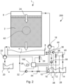
- Fig. 2 schematically illustrate a system 200 according to a second example. 15.
- the system of fig. 2 corresponds to the system of fig.1 with the difference that the control device 100 is configured to supply the first cleaning fluid 12 and/or the second cleaning fluid 14 to the cooling and humidification media 2 by supplying the first cleaning fluid 12 and/or the second cleaning fluid 14 to the fluid distribution element 6.
- the first cleaning fluid 12 and/or the second cleaning fluid 14 are supplied to the fluid distribution element 6 by the third fluid pump 36.
- a regulator valve 44 is arranged between the third fluid pump 36 and the fluid distribution element 6. Before reaching the fluid distribution element 6, the first cleaning fluid 12 and/or the second cleaning fluid 14 will pass the regulator valve 44, which is arranged between the third fluid pump 36 and the fluid distribution element 6.
- Fig. 3 schematically illustrate a system 200 according to a third example.
- the system of fig. 3 corresponds to the system of fig. 1 with the difference that the sensor device 10 is arranged in the tray 8.
- the sensor device 10 is configured to be in contact with fluid 4 in the tray 8.
- the container 16 comprises a container for the first cleaning fluid 12 and a container for the second cleaning fluid 14.
- the fluid supply tank 20 and the containers 16 for the first cleaning fluid 12 and a container for the second cleaning fluid 14 are in fluid connection with the tray 8 by means of fluid pipes.
- the second fluid pump 22 is configured to suck the fluid 4 from the fluid supply tank 20 and also from the containers 16 for the first cleaning fluid 12 and the second cleaning fluid 14.
- a fourth valve 46 is arranged between the fluid supply tank 20 and the second fluid pump 22.
- the fluid distribution element 6 comprises connection means 52, for connecting the fluid distribution element 6 to the additional cooling and humidification media 2'.
- the additional fluid distribution element 6' is configured to transfer the fluid 4, which is distributed by the additional fluid distribution element 6', to the additional cooling and humidification media 2' and further to the cooling and humidification media 2.
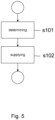
- Determining s101 the condition of the cooling and humidification media 2 comprises determining the pH-value, hardness, turbidity, salt content, and/or presence of bacteria/fungi in the fluid 4 downstream of the cooling and humidification media 2.
- Supplying s102 at least one cleaning fluid 12; 14 to the cooling and humidification media 2 dependent on the condition of the cooling and humidification media 2 comprises determining a dosage of the at least one cleaning fluid 12; 14 based on the condition of the cooling and humidification media 2.
- Supplying s102 at least one cleaning fluid 12; 14 to the cooling and humidification media 2 comprises supplying the at least one cleaning fluid 12; 14 to the tray 8.
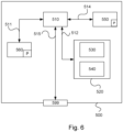
- the programme P may be stored in an executable form or in a compressed form in a memory 560 and/or in a read/write memory 550.
- Parts of the methods herein described may be effected by the device 500 by means of the data processing unit 510 which runs the programme stored in the memory 560 or the read/write memory 550. When the device 500 runs the programme, methods herein described are executed.
Landscapes
- Engineering & Computer Science (AREA)
- Mechanical Engineering (AREA)
- General Engineering & Computer Science (AREA)
- Chemical & Material Sciences (AREA)
- Combustion & Propulsion (AREA)
- Physics & Mathematics (AREA)
- Thermal Sciences (AREA)
- Life Sciences & Earth Sciences (AREA)
- Sustainable Development (AREA)
- Air Conditioning Control Device (AREA)
- Air Humidification (AREA)
- Heat-Exchange Devices With Radiators And Conduit Assemblies (AREA)
Description
- The invention relates to a method, performed by a control device, for cleaning an evaporative humidifier and cooler apparatus, and also to a system comprising an evaporative humidifier and cooler apparatus according to the appended claims. Further, the invention relates to a computer program and to a computer-readable medium according to the appended claims.
- Evaporative humidifiers and cooler apparatuses are used to humidify and cool different types of spaces in buildings. Electric equipment within a building may generate heat, which increases the temperature within the building. Increased temperature may decrease the performance of the equipment. Electric equipment may also be sensitive to static electricity. If the humidity in a space within the building falls below a certain level, static electricity may be generated.
- Evaporative humidifiers and cooler apparatuses comprises an inorganic non-combustible cooling and humidification media, also known as an evaporative media. Fluid, such as water, is supplied to the top of the evaporative media via a fluid distribution element. The water flows down the evaporative media, which may have a corrugated surface. As warm and dry air passes through the evaporative media, it evaporates a proportion of the water and thus produces cold, humidified air. The rest of the water assists in washing and cleaning the evaporative media, and is drained to a fluid tray. The warm and dry air may be directed through the evaporative media by means of a forced air flow, which is generated by a fan.
- The energy that is needed for the evaporation of the fluid is taken from the air itself. The air that leaves the apparatus is therefore humidified and cooled simultaneously without any external energy supply for the evaporation due to an adiabatic cooling process.
- The tray is filled with fluid from a fluid supply. When there is a humidity and cooling demand, a pump starts and circulates the fluid over the evaporative media via the fluid distribution element. The fluid may contain a certain amount of minerals and salts with a predetermined concentration. During the evaporation, the fluid is released to the air. The minerals and salts remain in the fluid and are returned to the fluid tray. A proportion of the fluid in the fluid tray is continually drained and replaced with fresh fluid from the supply in order to control the mineral concentration.
-
US 2005/079124 A1 discloses a system and a method for air cleaning by the means of chlorine dioxide. The device is provided with humidification media configured to receive an evaporative fluid, a fluid distribution element for distributing the fluid, a tray for collecting the fluid according to the preamble ofclaim 1 andclaim 6 respectively. -
DE 20 2012 011401 U1 discloses a device for humidification of an airflow wherein a pH-value of the aqueous solution is controlled and an acid or a brine is added accordingly. -
WO 2019/130345 A1 discloses a system for cooling a fluid comprising a filter unit a pump and a tray for collecting the fluid wherein a cleaning agent for descaling is added to the fluid either on a regular scheduled basis or when scale is visually identified on the surface of the tank, the evaporative pads or the pipes. - In addition to the remaining minerals and salts in the fluid, also bacteria and fungi may be formed in the fluid and on the cooling and humidification media. Minerals, salt, bacteria and/or fungi in the fluid may also result in deposits and sediments on the cooling and humidification media, resulting in a need for de-scaling of the cooling and humidification media.
- Thus, there is a need to develop a method for cleaning an evaporative humidifier and cooler apparatus, which is based on the condition of a cooling and humidification media of the apparatus. There is also a need to develop a computer program and a computer-readable medium for executing the method. Also, there is a need to develop a system comprising an evaporative humidifier and cooler apparatus for humidification and cooling of air, which evaporative humidifier and cooler apparatus is cleaned based on the condition of a cooling and humidification media of the apparatus.
- The object of the invention is therefore to develop a method for cleaning an evaporative humidifier and cooler apparatus, which is based on the condition of a cooling and humidification media of the apparatus.
- A further object of the invention is to develop a computer program and a computer-readable medium for executing the method.
- Another object of the invention is to develop a system comprising an evaporative humidifier and cooler apparatus for humidification and cooling of air, which evaporative humidifier and cooler apparatus is cleaned based on the condition of a cooling and humidification media of the apparatus.
- In order to achieve the above objects there is proposed a method for cleaning an evaporative humidifier and cooler apparatus according to
claim 1 and a system comprising an evaporative humidifier and cooler apparatus according toclaim 6. - Further, the above objects are achieved by a computer program as defined in
claim 8 and computer-readable medium as defined in claim 7. Preferred embodiments are defined in the dependent claims. - According to an aspect of the invention a method, performed by a control device, for cleaning an evaporative humidifier and cooler apparatus for humidification and cooling of air is provided. The apparatus comprises: a cooling and humidification media, which is configured to receive and evaporate a fluid; a fluid distribution element, which is configured to distribute the fluid to the cooling and humidification media; and a tray arranged to collect fluid downstream of the cooling and humidification media; wherein the fluid distributed by the fluid distribution element is collected from the tray. The method comprises: determining the condition of the cooling and humidification media based on data from a sensor device arranged in fluid communication with the fluid downstream of the cooling and humidification media; and supplying at least one cleaning fluid to the cooling and humidification media dependent on the condition of the cooling and humidification media, wherein the method further comprises:
supplying at least one cleaning fluid to the cooling and humidification media dependent on the condition of the cooling and humidification media, wherein supplying the at least one cleaning fluid to the cooling and humidification media comprises supplying a first cleaning fluid when the cooling and humidification media has a condition requiring de-scaling of the cooling and humidification media and/or supplying a second cleaning fluid when the cooling and humidification media has a condition requiring disinfection of the cooling and humidification media. - The evaporative humidifier and cooler apparatus will be cleaned dependent on the condition of the cooling and humidification media. The sensor device is configured to detect characteristics of the fluid. Based on data achieved from the detection of the characteristics of the fluid, the condition of the cooling and humidification media can be determined. The type of cleaning is performed based on the condition of the cooling and humidification media. Dependent on the condition of the cooling and humidification media, at least one cleaning fluid is supplied to the cooling and humidification media. The data from the sensor device is communicated to the control device. The data is processed in the control device and based on the data from the sensor device a suitable cleaning fluid or a combination of cleaning fluids may be supplied to the cooling and humidification media. The at least one cleaning fluid may be supplied directly to the cooling and humidification media or to the fluid, which is distributed by the fluid distribution element to the cooling and humidification media. When supplying the at least one cleaning fluid to the cooling and humidification media, the evaporative humidifier and cooler apparatus will be cleaned.
- The fluid used in the apparatus will contain a certain amount of substances, such as salts and minerals, the concentration of which varies from place to place. During the cooling and humidification process, fluid free from such substances is released to the air. The substances remain in the fluid in the apparatus and are returned to the fluid tray. The method will keep the surface of the cooling and humidification media clean. The result is that the service life of the cooling and humidification media may be significantly extended.
- According to an aspect of the invention a system comprising an evaporative humidifier and cooler apparatus for humidification and cooling of air, a control device and a sensor device arranged in communication with the control device is provided. The apparatus comprising: a cooling and humidification media, which is configured to receive and evaporate a fluid; a fluid distribution element, which is configured to distribute the fluid to the cooling and humidification media; and a tray arranged to collect fluid downstream of the cooling and humidification media; wherein the fluid distributed by the fluid distribution element is collected from the tray; and wherein the control device is configured to determine the condition of the cooling and humidification media based on data from the sensor device arranged in fluid communication with the fluid downstream of the cooling and humidification media; and wherein at least one cleaning fluid is supplied to the cooling and humidification media by a fluid pump via the fluid distribution element dependent on the condition of the cooling and humidification media, wherein the control device configured to supply the at least one cleaning fluid to the cooling and humidification media comprises supplying a first cleaning fluid when the cooling and humidification media has a condition requiring de-scaling of the cooling and humidification media; and/or wherein the control device configured to supply the at least one cleaning fluid to the cooling and humidification media comprises supplying a second cleaning fluid when the cooling and humidification media has a condition requiring disinfection of the cooling and humidification media.
- The evaporative humidifier and cooler apparatus of the system will be cleaned by the at least one cleaning fluid. The sensor device is arranged in fluid communication with the fluid downstream of the cooling and humidification media. In a circulating process, where the fluid is collected in a tray after the fluid has passed the cooling and humidification media, the fluid is brought back to the cooling and humidification media by for an example a circulating pump. Thus, the sensor device may be arranged in fluid communication with the fluid at any position in a circuit containing the cooling and humidification media, since any position in a circuit will be a position downstream of the cooling and humidification media. Data from the sensor device is communicated to the control device. The data is processed in the control device. Based on the data, the condition of the cooling and humidification media can be determined and thus a suitable cleaning fluid or a combination of cleaning fluids may be supplied to the cooling and humidification media. When supplying the at least one cleaning fluid to the cooling and humidification media, the evaporative humidifier and cooler apparatus will be cleaned.
- The apparatus of the system uses the physical principle of fluid evaporation. Air is forced through the cooling and humidification media by a fan. While the air passes through the wet cooling and humidification media, it releases heat to the fluid, thereby cooling itself. The quantity of moisture present in the air determines the level of temperature reduction of the air treated.
- Additional objectives, advantages and novel features of the invention will be apparent to one skilled in the art from the following details, and through exercising the invention. While the invention is described below, it should be apparent that modifications can be made by one skilled in the art, without departing from the scope of the appended claims.
- For fuller understanding of the present disclosure and further objects and advantages of it, the detailed description set out below should be read together with the accompanying drawings, in which the same reference notations denote similar items in the various figures, and in which:
-
Figures 1 - 4 schematically illustrate systems according to different examples; -
Fig. 5 shows a flowchart of a method according to an example; and -
Fig. 6 schematically illustrates a control device or computer according to an example. - According to the present invention, a method, performed by a control device, for cleaning an evaporative humidifier and cooler apparatus for humidification and cooling of air is provided. The apparatus comprises: a cooling and humidification media, which is configured to receive and evaporate a fluid; a fluid distribution element, which is configured to distribute the fluid to the cooling and humidification media; and a tray arranged to collect fluid downstream of the cooling and humidification media; wherein the fluid distributed by the fluid distribution element is collected from the tray. The method comprises: determining the condition of the cooling and humidification media based on data from a sensor device arranged in fluid communication with the fluid downstream of the cooling and humidification media; and supplying at least one cleaning fluid to the cooling and humidification media dependent on the condition of the cooling and humidification media.
- Such method is performed by a control device. The control device may be a component of the evaporative humidifier and cooler apparatus or a component independent and arranged at a distance from the evaporative humidifier and cooler apparatus. The evaporative humidifier and cooler apparatus may be configured for humidification of air. Thus, the apparatus may increase the humidity in air or keep the humidity in air at a predetermined level. The apparatus may also decrease the temperature of air or keep the temperature at a constant level. The cooling and humidification media is made of a material which is able to receive and evaporate a fluid. The cooling and humidification media may have a corrugated surface, which increases the surface of the media. The cooling and humidification media may be arranged in cassettes, which are supported by a rigid frame of the apparatus. The fluid, received and evaporated by the media, may be water or any other suitable fluid which may be evaporated by the media. The fluid may preferably be environmentally friendly.
- The fluid distribution element is configured to distribute the fluid to the cooling and humidification media. The fluid may flow over and through the cooling and humidification media by means of gravity. A first fluid pump may be connected to the fluid distribution element, wherein the first fluid pump is configured to deliver fluid to the fluid distribution element. The first fluid pump may suck the fluid from the tray and deliver the fluid to the fluid distribution element. The first fluid pump may be driven by and electric motor. The first fluid pump may be driven at different speeds in order to deliver fluid to the fluid distribution element with different flow rates and different volume flows. During start up of the apparatus, an increased flow of fluid may be provided by the first fluid pump to the fluid distribution element, in order to increase the wetting of the cooling and humidification media. When the cooling and humidification media has absorbed the fluid, and is completely wet, the flow of fluid provided by the first fluid pump may be reduced to a normal fluid delivery level. When shutting down the apparatus, the first fluid pump is stopped, so no fluid is delivered to the fluid distribution element. The fluid distribution element may be connected to the frame of the cassette. The fluid distribution element may be an elongated sprinkler, arranged at the top of the media. The fluid distribution element may have small calibrated holes orientated upwards. This design feature prevents the clogging and thus ensures efficient water distribution over the entire cooling and humidification media. Efficient water distribution over the entire cooling and humidification media is also ensured even in cases where the cooling and humidification media are not perfectly horizontally aligned, for example due to ground movements. Alternatively, or in combination with the elongated sprinkler, a single fluid nozzle may be arranged to distribute fluid to the media.
- The tray is arranged to collect fluid downstream of the cooling and humidification media. Fluid distributed to the cooling and humidification media will be released to the surrounding air in the space to be treated by the evaporative humidifier and cooler apparatus. However, not all fluid distributed to the media will be released to the surrounding air and therefore fluid may flow by means of gravity along the media and into the tray arranged downstream or below the media. As mentioned above, the first fluid pump may suck the fluid from the tray and deliver the fluid to the fluid distribution element. Since fluid is released to the surrounding air, fluid should continuously be supplied to the tray from a fluid supply tank or from a fluid pipe network. The fluid from the fluid supply tank or from the fluid pipe network may be supplied to the tray by a second fluid pump. A proportion of the fluid in the tray may continually be drained and replaced with fresh fluid from the fluid supply tank to control the concentration of unwanted substances in the fluid.
- The evaporative humidifier and cooler apparatus will be cleaned dependent on the condition of the cooling and humidification media. The sensor device is configured to detect characteristics of the fluid. Based on data achieved from the detection of the characteristics of the fluid, the condition of the cooling and humidification media can be determined. The type of cleaning is performed based on the condition of the cooling and humidification media. Dependent on the condition of the cooling and humidification media, at least one cleaning fluid is supplied to the cooling and humidification media. The data from the sensor device is communicated to the control device. The data is processed in the control device and based on the data from the sensor device a suitable cleaning fluid or a combination of cleaning fluids may be supplied to the cooling and humidification media. The at least one cleaning fluid may be supplied directly to the cooling and humidification media or to the fluid, which is distributed by the fluid distribution element to the cooling and humidification media. When supplying the at least one cleaning fluid to the cooling and humidification media, the evaporative humidifier and cooler apparatus will be cleaned.
- According to an aspect, determining the condition of the cooling and humidification media comprises determining the pH-value, hardness, turbidity, salt content, and/or presence of bacteria/fungi in the fluid downstream of the cooling and humidification media.
- The sensor device is configured to detect characteristics of the fluid connected to the pH-value, hardness, turbidity, salt content, and/or presence of bacteria/fungi in the fluid. Based on these detected characteristics of the fluid, data is achieved from the sensor device for determining the pH-value, hardness, turbidity, salt content, and/or presence of bacteria/fungi in the fluid. Alternatively, the data achieved from the sensor device is processed in the control device in order to determining the pH-value, hardness, turbidity, salt content, and/or presence of bacteria/fungi in the fluid. Based on this information, the condition of the cooling and humidification media may be determined. The sensor device may be arranged in the tray and in contact with the fluid in the tray.
- According to an aspect, supplying at least one cleaning fluid to the cooling and humidification media dependent on the condition of the cooling and humidification media comprises determining a dosage of the at least one cleaning fluid based on the condition of the cooling and humidification media.
- The sensor is configured to detect characteristics of the fluid connected to the pH-value, hardness, turbidity, salt content, and/or presence of bacteria/fungi in the fluid. The concentration or grade of the pH-value, hardness, turbidity, salt, and/or bacteria/fungi in the fluid may be detected by the sensor device. Based on this information, the condition of the cooling and humidification media may be determined, and thus a dosage of the at least one cleaning fluid may be determined. The dosage of the at least one cleaning fluid may also be dependent on the characteristics of the at least one cleaning fluid. The at least one cleaning fluid may preferably be environmentally friendly.
- According to an aspect, supplying at least one cleaning fluid to the cooling and humidification media comprises supplying the at least one cleaning fluid to the tray.
- A first fluid pump may be connected to the fluid distribution element, wherein the first fluid pump is configured to deliver fluid to the fluid distribution element. The fluid distribution element is configured to distribute the fluid to the cooling and humidification media. The first fluid pump may suck the fluid from the tray and deliver the fluid to the fluid distribution element. Supplying the at least one cleaning fluid to the tray results in that the cleaning fluid will be mixed with the fluid in the tray. The blended fluid in the tray and the cleaning fluid are supplied to the fluid distribution element, which distributes the blended fluid in the tray and the cleaning fluid the cooling and humidification media for cleaning the cooling and humidification media. The blended fluid in the tray and the cleaning fluid may be supplied to the fluid distribution element by the first fluid pump. The at least one cleaning fluid may be supplied to the tray by a third fluid pump. Alternatively, the tray may be drained before supplying the cleaning fluid to the tray. When the cleaning fluid has been supplied to the tray, the cleaning fluid is supplied to the fluid distribution element, which distributes the cleaning fluid to the cooling and humidification media for cleaning the cooling and humidification media. In this case, only cleaning fluid may be supplied to the fluid distribution element by the first fluid pump.
- According to an aspect, supplying the at least one cleaning fluid to the cooling and humidification media comprises supplying the at least one cleaning fluid to the fluid distribution element.
- The first fluid pump may be connected to the fluid distribution element, wherein the first fluid pump is configured to deliver fluid to the fluid distribution element. The first fluid pump may suck the fluid from the tray and deliver the fluid to the fluid distribution element. The at least one cleaning fluid may be supplied to the fluid distribution element by a third fluid pump. Before reaching fluid distribution element, the at least one cleaning fluid may pass a regulator valve, which is arranged between the third fluid pump and the fluid distribution element. Also the fluid sucked from the tray by means of the first fluid pump may pass the regulator valve. The at least one cleaning fluid to may be mixed with the fluid in the tray by regulating the regulator valve. The blended fluid in the tray and the cleaning fluid may be supplied to the fluid distribution element by the first fluid pump. Alternatively, the regulator valve may close the connection between the tray and the fluid distribution element, so that only cleaning fluid is supplied to the fluid distribution element, which distributes the cleaning fluid to the cooling and humidification media for cleaning the cooling and humidification media.
- According to an aspect, determining the condition of the cooling and humidification media comprises circulating fluid from the tray to a container comprising the sensor device.
- The container may be separated from the tray. The fluid in the container may be separated from the fluid in the tray. The fluid from the tray may be circulated to the container by a fourth fluid pump. The sensor device may be arranged in the container and in contact with the fluid circulated from the tray. The fluid in the container may be circulated back to the tray by a fifth fluid pump. Such container with the sensor device may be connectable to a tray of an evaporative humidifier and cooler apparatus in order to determining the condition of the cooling and humidification media.
- According to the present invention, supplying the at least one cleaning fluid to the cooling and humidification media comprises supplying a first cleaning fluid when the cooling and humidification media has a condition requiring de-scaling of the cooling and humidification media, and/or supplying the at least one cleaning fluid to the cooling and humidification media comprises supplying a second cleaning fluid when the cooling and humidification media has a condition requiring disinfection of the cooling and humidification media.
- Minerals, salt, bacteria and/or fungi in the fluid may result in deposits and sediments on the cooling and humidification media, may result in a need for de-scaling of the cooling and humidification media. By detecting characteristics of the fluid connected to the pH-value, hardness, turbidity, salt content, and/or presence of bacteria/fungi in the fluid, the sensor device alone or the control device may determine if the cooling and humidification media has a condition requiring de-scaling of the cooling and humidification media. The first cleaning fluid has characteristics, which will clean the cooling and humidification media from deposits and thus de-scaling of the cooling and humidification media. De-scaling the cooling and humidification media is a result of cleaning the evaporative humidifier and cooler apparatus. The first cleaning fluid may preferably be environmentally friendly.
- Minerals, salt, bacteria and/or fungi in the fluid may result in a need of disinfection of the cooling and humidification media. By detecting characteristics of the fluid connected to the pH-value, hardness, turbidity, salt content, and/or presence of bacteria/fungi in the fluid, the sensor device alone or the control device may determine if the cooling and humidification media has a condition which requires disinfection of the cooling and humidification media. The second cleaning fluid has characteristics, which will clean the cooling and humidification media from minerals, salt, bacteria and/or fungi and thus disinfect the cooling and humidification media. Disinfection of the cooling and humidification media is a result of cleaning the evaporative humidifier and cooler apparatus. The second cleaning fluid may preferably be environmentally friendly.
- The present invention also relates to a computer program comprising instructions which, when the program is executed by a computer, causes the computer to carry out the method disclosed above. The invention further relates to a computer-readable medium comprising instructions, which when executed by a computer causes the computer to carry out the method disclosed above. The method may be comprised in pre-programmed software, which may be implemented into the drilling unit suitable for utilizing the method. The pre-programmed software may be stored in the control device. Alternatively, or in combination, the software may be stored in a memory or in computer at a distance from the control device.
- According to the present invention, a system comprising an evaporative humidifier and cooler apparatus for humidification and cooling of air, a control device and a sensor device arranged in communication with the control device is provided. The apparatus comprising: a cooling and humidification media, which is configured to receive and evaporate a fluid; a fluid distribution element, which is configured to distribute the fluid to the cooling and humidification media; and a tray arranged to collect fluid downstream of the cooling and humidification media; wherein the fluid distributed by the fluid distribution element is collected from the tray; and wherein the control device is configured to determine the condition of the cooling and humidification media based on data from the sensor device arranged in fluid communication with the fluid downstream of the cooling and humidification media; and supply at least one cleaning fluid to the cooling and humidification media dependent on the condition of the cooling and humidification media.
- The evaporative humidifier and cooler apparatus of the system will be cleaned by the at least one cleaning fluid. The sensor device is arranged in fluid communication with the fluid downstream of the cooling and humidification media. In a circulating process, where the fluid is collected in a tray after the fluid has passed the cooling and humidification media, the fluid is brought back to the cooling and humidification media by for an example a circulating pump. Thus, the sensor device may be arranged in fluid communication with the fluid at any position in a circuit containing the cooling and humidification media, since any position in a circuit will be a position downstream of the cooling and humidification media. Data from the sensor device is communicated to the control device. The data is processed in the control device. Based on the data, the condition of the cooling and humidification media can be determined and thus a suitable cleaning fluid or a combination of cleaning fluids may be supplied to the cooling and humidification media. When supplying the at least one cleaning fluid to the cooling and humidification media, the evaporative humidifier and cooler apparatus will be cleaned.
- It will be appreciated that all the examples described for the method aspect of the invention performed by the control device are also applicable to the system aspect of the invention. That is, the control device of the system may be configured to perform any one of the steps of the method according to the various examples described above. Thus, according to the following aspects, the control device of the system may be configured to perform the method steps according to the corresponding examples and aspects described above.
- According to an aspect, the control device may thus be configured to determine the condition of the cooling and humidification media by determining the pH-value, hardness, turbidity, salt content, and/or presence of bacteria/fungi in the fluid downstream of the cooling and humidification media. According to a further aspect, the control device may be configured to supply the at least one cleaning fluid to the cooling and humidification media dependent on the condition of the cooling and humidification media by determining a dosage of the at least one cleaning fluid based on the condition of the cooling and humidification media. According to a further aspect, the control device may be configured to supply the at least one cleaning fluid to the cooling and humidification media by supplying the at least one cleaning fluid to the tray. According to a further aspect, the control device may be configured to supply the at least one cleaning fluid to the cooling and humidification media by supplying the at least one cleaning fluid to the fluid distribution element. According to a further aspect, the system may further comprising a container comprising the sensor device, the container being arranged in fluid communication with the tray, wherein the control device is configured to circulate fluid from the tray to the container. According to a further aspect, the control device is configured to supply the at least one cleaning fluid to the cooling and humidification media comprises supplying a first cleaning fluid when the cooling and humidification media has a condition requiring de-scaling of the cooling and humidification media. According to a further aspect, the control device may be configured to supply the at least one cleaning fluid to the cooling and humidification media comprises supplying a second cleaning fluid when the cooling and humidification media has a condition requiring disinfection of the cooling and humidification media.
- The fluid pumps described above may be driven by electric motors.
- The method, performed by a control device, for cleaning an evaporative humidifier and cooler apparatus, the system comprising an evaporative humidifier and cooler apparatus, the computer program and the computer-readable medium will now be described together with the appended drawings.
-
Fig. 1 schematically illustrate asystem 200 according to a first example. The system comprising an evaporative humidifier andcooler apparatus 1 for humidification and cooling of air. Acontrol device 100 is provided, which is connected to asensor device 10. Theapparatus 1 comprising a cooling andhumidification media 2, which is configured to receive and evaporate afluid 4. Afluid distribution element 6 is configured to distribute thefluid 4 to the cooling andhumidification media 2. Atray 8 is arranged to collectfluid 4 downstream of the cooling andhumidification media 2. Thefluid 4 distributed by thefluid distribution element 6 is collected from thetray 8. Afirst fluid pump 18 is be connected to thefluid distribution element 6, wherein thefirst fluid pump 18 is configured to deliverfluid 4 to thefluid distribution element 6. Thefirst fluid pump 18 is arranged at a fluid pipe arranged between thetray 8 and thefluid distribution element 6. Thefirst fluid pump 18 may suck the fluid 4 from thetray 8 and deliver thefluid 4 to thefluid distribution element 6. Afluid supply tank 20 is in fluid connection with thetray 8 by a fluid pipe.Fluid 4 may be supplied to thetray 8 from thefluid supply tank 20. The fluid 4 from thefluid supply tank 20 is supplied to thetray 8 by asecond fluid pump 22. Vertically directed arrows 23 represent the direction offluid 4 through thefluid distribution element 6, the cooling andhumidification media 2 and further to afluid tray 8. Adrain valve 24 is arranged at thetray 8 and thefluid 4 in thetray 8 is may be drained via thedrain valve 24. Anadditional sensor device 26 may be connected to thecontrol device 100, whichadditional sensor device 26 is may detect temperature and humidity in the air surrounding theapparatus 1. - The
control device 100 is configured to determine the condition of the cooling andhumidification media 2 based on data from thesensor device 10 arranged in fluid communication with thefluid 4 downstream of the cooling andhumidification media 2. The condition of the cooling andhumidification media 2 may be determined by determining the pH-value, hardness, turbidity, salt content, and/or presence of bacteria/fungi in thefluid 4 downstream of the cooling andhumidification media 2. Depending on the condition of the media 2 afirst cleaning fluid 12 and/or asecond cleaning fluid 14 will be supplied to the cooling andhumidification media 2. - A
container 16 is provided, which contains thefluid 4 and the first andsecond cleaning fluids fluids partition walls 28 arranged in thecontainer 16. Three independent containers may also constitute thecontainer 16. According to the first example, the part of thecontainer 16 comprising thefluid 4 is arranged in fluid communication with thetray 8 by means of a pipes comprising afourth fluid pump 30 and afifth fluid pump 32 and afirst valve 34. The part of thecontainer 16 containing thefluid 4 also comprising thesensor device 10. Thecontrol device 100 is configured to circulate fluid 4 from thetray 8 to the part of thecontainer 16 containing thefluid 4. The parts of thecontainer 16 containing the first andsecond cleaning fluids tray 8 by pipes comprising athird fluid pump 36 and asecond valve 38 andthird valve 40. - The
control device 100 is configured to supply the first and/orsecond cleaning fluid humidification media 2 by supplying the first and/or cleaningfluid tray 8. Thecontrol device 100 is configured to supply afirst cleaning fluid 12 to the cooling andhumidification media 2 when the cooling andhumidification media 2 has a condition requiring de-scaling of the cooling andhumidification media 2. Thecontrol device 100 is configured to supply asecond cleaning fluid 14 to the cooling andhumidification media 2 when the cooling andhumidification media 2 has a condition requiring disinfection of the cooling andhumidification media 2. In addition, based on the condition of the cooling andhumidification media 2, thecontrol device 100 is configured to determine a dosage of the first and/or cleaningfluid - A
fan 42 is configured to generate an air flow through the cooling andhumidification media 2. Thefan 42 may generate a forced air flow through the cooling andhumidification media 2. Thefan 42 may be arranged behind the cooling andhumidification media 2 and thus force the air flow through the cooling andhumidification media 2 by a pressure. Alternatively, or in combination, afan 42 may be arranged in front of the cooling andhumidification media 2 and thus force the air flow through the cooling andhumidification media 2 by sucking the air flow through the cooling andhumidification media 2. Thefan 42 may generate a regulated forced air flow through the first and second cooling andhumidification media 2. -
Fig. 2 schematically illustrate asystem 200 according to a second example. 15. The system offig. 2 corresponds to the system offig.1 with the difference that thecontrol device 100 is configured to supply thefirst cleaning fluid 12 and/or thesecond cleaning fluid 14 to the cooling andhumidification media 2 by supplying thefirst cleaning fluid 12 and/or thesecond cleaning fluid 14 to thefluid distribution element 6. Thefirst cleaning fluid 12 and/or thesecond cleaning fluid 14 are supplied to thefluid distribution element 6 by thethird fluid pump 36. Aregulator valve 44 is arranged between thethird fluid pump 36 and thefluid distribution element 6. Before reaching thefluid distribution element 6, thefirst cleaning fluid 12 and/or thesecond cleaning fluid 14 will pass theregulator valve 44, which is arranged between thethird fluid pump 36 and thefluid distribution element 6. Also thefluid 4 sucked from thetray 8 by means of thefirst fluid pump 18 may pass theregulator valve 44. Thefirst cleaning fluid 12 and/or thesecond cleaning fluid 14 may be mixed with thefluid 4 in thetray 8 by regulating theregulator valve 44. The fluid in thetray 8 and thefirst cleaning fluid 12 and/or thesecond cleaning fluid 14 may together be supplied to thefluid distribution element 6 by thefirst fluid pump 18. Alternatively, theregulator valve 44 may close the connection between thetray 8 and the fluid distribution element, so that only thefirst cleaning fluid 12 and/or thesecond cleaning fluid 14 is supplied to thefluid distribution element 6, which distributes thefirst cleaning fluid 12 and/or thesecond cleaning fluid 14 to the cooling andhumidification media 2 for cleaning the cooling andhumidification media 2. -
Fig. 3 schematically illustrate asystem 200 according to a third example. The system offig. 3 corresponds to the system offig. 1 with the difference that thesensor device 10 is arranged in thetray 8. Thesensor device 10 is configured to be in contact withfluid 4 in thetray 8. Thecontainer 16 comprises a container for thefirst cleaning fluid 12 and a container for thesecond cleaning fluid 14. Thefluid supply tank 20 and thecontainers 16 for thefirst cleaning fluid 12 and a container for thesecond cleaning fluid 14 are in fluid connection with thetray 8 by means of fluid pipes. Thesecond fluid pump 22 is configured to suck the fluid 4 from thefluid supply tank 20 and also from thecontainers 16 for thefirst cleaning fluid 12 and thesecond cleaning fluid 14. Afourth valve 46 is arranged between thefluid supply tank 20 and thesecond fluid pump 22. -
Fig. 4 schematically illustrate asystem 200 according to a fourth example. The system offig. 4 corresponds to the system offig. 3 with the difference that an additional cooling and humidification media 2' and an additional fluid distribution element 6' are arranged on and above the cooling andhumidification media 2 and thefluid distribution element 6 shown infig. 3 . Thetray 8 is in fluid communication with both the cooling andhumidification media 2 and thefluid distribution element 6, and the additional cooling and humidification media 2' and an additional fluid distribution element 6' via fluid pipes. Afifth valve 48 is arranged between thefirst fluid pump 18 and thefluid distribution element 6. Asixth valve 50 is arranged between thefirst fluid pump 18 and the additional fluid distribution element 6'. The fifth andsixth valves - The
fluid distribution element 6 comprises connection means 52, for connecting thefluid distribution element 6 to the additional cooling and humidification media 2'. The additional fluid distribution element 6' is configured to transfer thefluid 4, which is distributed by the additional fluid distribution element 6', to the additional cooling and humidification media 2' and further to the cooling andhumidification media 2. -
Fig. 5 shows a flowchart of a method according to an example. The method is performed by acontrol device 100, for cleaning an evaporative humidifier andcooler apparatus 1 for humidification and cooling of air. The method thus relates to thesystem 200 comprising theapparatus 1 disclosed infigures 1 - 4 . Theapparatus 1 comprises a cooling andhumidification media 2, which is configured to receive and evaporate afluid 4; afluid distribution element 6, which is configured to distribute thefluid 4 to the cooling andhumidification media 2; and atray 8 arranged to collectfluid 4 downstream of the cooling andhumidification media 2; wherein thefluid 4 distributed by thefluid distribution element 6 is collected from thetray 8. - The method comprising: determining s101 the condition of the cooling and
humidification media 2 based on data from asensor device 10 arranged in fluid communication with thefluid 4 downstream of the cooling andhumidification media 2; and supplying s102 at least one cleaningfluid 12; 14 to the cooling andhumidification media 2 dependent on the condition of the cooling andhumidification media 2. - Determining s101 the condition of the cooling and
humidification media 2 comprises determining the pH-value, hardness, turbidity, salt content, and/or presence of bacteria/fungi in thefluid 4 downstream of the cooling andhumidification media 2. Supplying s102 at least one cleaningfluid 12; 14 to the cooling andhumidification media 2 dependent on the condition of the cooling andhumidification media 2 comprises determining a dosage of the at least one cleaningfluid 12; 14 based on the condition of the cooling andhumidification media 2. Supplying s102 at least one cleaningfluid 12; 14 to the cooling andhumidification media 2 comprises supplying the at least one cleaningfluid 12; 14 to thetray 8. Supplying s102 the at least one cleaningfluid 12; 14 to the cooling andhumidification media 2 comprises supplying the at least one cleaningfluid 12; 14 to thefluid distribution element 6. Determining s101 the condition of the cooling andhumidification media 2 comprises circulating fluid from thetray 8 to acontainer 16 comprising thesensor device 10. Supplying s102 the at least one cleaningfluid 12; 14 to the cooling andhumidification media 2 comprises supplying afirst cleaning fluid 12 when the cooling andhumidification media 2 has a condition requiring de-scaling of the cooling andhumidification media 2. Supplying s102 the at least one cleaningfluid 12; 14 to the cooling andhumidification media 2 comprises supplying asecond cleaning fluid 14 when the cooling andhumidification media 2 has a condition requiring disinfection of the cooling andhumidification media 2. -
Fig. 6 schematically illustrates a diagram of a version of adevice 500. The control device 25 described with reference tofig. 1 may in a version comprise thedevice 500. Thedevice 500 comprises anon-volatile memory 520, adata processing unit 510 and a read/write memory 550. Thenon-volatile memory 520 has afirst memory element 530 in which a computer programme, e.g. an operating system, is stored for controlling the function of thedevice 500. Thedevice 500 further comprises a bus controller, a serial communication port, I/O means, an A/D converter, a time and date input and transfer unit, an event counter and an interruption controller (not depicted). Thenon-volatile memory 520 has also asecond memory element 540. - There is provided a computer programme P which comprises instructions for carry out the above-mentioned method. The programme P may be stored in an executable form or in a compressed form in a
memory 560 and/or in a read/write memory 550. - Where the
data processing unit 510 is described as performing a certain function, it means that thedata processing unit 510 effects a certain part of the programme stored in thememory 560 or a certain part of the programme stored in the read/write memory 550. - The
data processing device 510 can communicate with adata port 599 via adata bus 515. Thenon-volatile memory 520 is intended for communication with thedata processing unit 510 via adata bus 512. Theseparate memory 560 is intended to communicate with thedata processing unit 510 via adata bus 511. The read/write memory 550 is adapted to communicating with thedata processing unit 510 via adata bus 514. - When data are received on the
data port 599, they are stored temporarily in thesecond memory element 540. When input data received have been temporarily stored, thedata processing unit 510 is prepared to effect code execution as described above. - Parts of the methods herein described may be effected by the
device 500 by means of thedata processing unit 510 which runs the programme stored in thememory 560 or the read/write memory 550. When thedevice 500 runs the programme, methods herein described are executed. - The foregoing description of the preferred embodiments of the present invention is provided for illustrative and descriptive purposes. It is not intended to be exhaustive or to restrict the invention to the variants described. Many modifications and variations will obviously be apparent to one skilled in the art within the scope of the appended claims. The embodiments have been chosen and described in order best to explain the principles of the invention and its practical applications and hence make it possible for specialists to understand the invention.
Claims (12)
- A method, performed by a control device (100), for cleaning an evaporative humidifier and cooler apparatus (1) for humidification and cooling of air, the apparatus (1) comprises:a cooling and humidification media (2), which is configured to receive and evaporate a fluid (4);a fluid distribution element (6), which is configured to distribute the fluid (4) to the cooling and humidification media (2); anda tray (8) arranged to collect fluid (4) downstream of the cooling and humidification media (2);wherein the fluid (4) distributed by the fluid distribution element (6) is collected from the tray (8);wherein the method comprises:determining (s101) the condition of the cooling and humidification media (2) based on data from a sensor device (10) arranged in fluid communication with the fluid (4) downstream of the cooling and humidification media (2);characterized in that the method further comprises:
supplying (s102) at least one cleaning fluid (12; 14) to the cooling and humidification media (2) dependent on the condition of the cooling and humidification media (2), wherein supplying (s102) the at least one cleaning fluid (12; 14) to the cooling and humidification media (2) comprises supplying a first cleaning fluid (12) when the cooling and humidification media (2) has a condition requiring de-scaling of the cooling and humidification media (2) and/or supplying a second cleaning fluid (14) when the cooling and humidification media (2) has a condition requiring disinfection of the cooling and humidification media (2). - The method according to claim 1, wherein determining (s101) the condition of the cooling and humidification media (2) comprises determining the pH-value, hardness, turbidity, salt content, and/or presence of bacteria/fungi in the fluid (4) downstream of the cooling and humidification media (2).
- The method according to claim 1 or 2, wherein supplying (s102) at least one cleaning fluid (12; 14) to the cooling and humidification media (2) dependent on the condition of the cooling and humidification media (2) comprises determining a dosage of the at least one cleaning fluid (12; 14) based on the condition of the cooling and humidification media (2).
- The method according to any one of the preceding claims, wherein supplying (s102) at least one cleaning fluid (12; 14) to the cooling and humidification media (2) comprises supplying the at least one cleaning fluid (12; 14) to the tray (8), and/or supplying the at least one cleaning fluid (12; 14) to the fluid distribution element (6).
- The method according to any one of the preceding claims, wherein determining (s101) the condition of the cooling and humidification media (2) comprises circulating fluid from the tray (8) to a container (16) comprising the sensor device (10).
- A system (200) comprising an evaporative humidifier and cooler apparatus (1) for humidification and cooling of air, a control device (100) and a sensor device (10) arranged in communication with the control device (100), the apparatus (1) comprising:a cooling and humidification media (2), which is configured to receive and evaporate a fluid (4);a fluid distribution element (6), which is configured to distribute the fluid (4) to the cooling and humidification media (2); anda tray (8) arranged to collect fluid (4) downstream of the cooling and humidification media (2);wherein the fluid (4) distributed by the fluid distribution element (6) is collected from the tray (8); wherein the control device (100) is configured to determine the condition of the cooling and humidification media (2) based on data from the sensor device (10) arranged in fluid communication with the fluid (4) downstream of the cooling and humidification media (2); characterized in that at least one cleaning fluid (12; 14) is supplied to the cooling and humidification media (2) by a fluid pump (18; 22; 36) via the fluid distribution element (6) dependent on the condition of the cooling and humidification media (2); wherein the control device (100) configured to supply the at least one cleaning fluid (12; 14) to the cooling and humidification media (2) comprises supplying a first cleaning fluid (12) when the cooling and humidification media (2) has a condition requiring de-scaling of the cooling and humidification media (2); and/or wherein the control device (100) configured to supply the at least one cleaning fluid (12; 14) to the cooling and humidification media (2) comprises supplying a second cleaning fluid (14) when the cooling and humidification media (2) has a condition requiring disinfection of the cooling and humidification media (2).
- A computer program (P) comprising instructions which, when the program is executed by a data processing unit (510) of a control device (100) of an evaporative humidifier and cooler apparatus (1) according to claim 6, cause the control device (100) to carry out the method according to any of claims 1-5.
- A computer-readable medium having stored thereon the computer program of claim 7.
- The system (200) according to claim 6, wherein the control device (100) is configured to determine the condition of the cooling and humidification media (2) by determining the pH-value, hardness, turbidity, salt content, and/or presence of bacteria/fungi in the fluid (4) downstream of the cooling and humidification media (2).
- The system (200) according to claim 6 or 9, wherein the control device (100) is configured to supply the at least one cleaning fluid (12; 14) to the cooling and humidification media (2) dependent on the condition of the cooling and humidification media (2) by determining a dosage of the at least one cleaning fluid (12; 14) based on the condition of the cooling and humidification media (2).
- The system (200) according to any one of claims 6, 9 or 10 wherein the control device (100) is configured to supply the at least one cleaning fluid (12; 14) to the cooling and humidification media (2) by supplying the at least one cleaning fluid (12; 14) to the tray (8), and/or by supplying the at least one cleaning fluid (12; 14) to the fluid distribution element (6).
- The system (200) according to any one of claims 6, 9, 10 or 11, further comprising a container (16) comprising the sensor device (10), the container (16) being arranged in fluid communication with the tray (8), wherein the control device (100) is configured to circulate fluid (4) from the tray (8) to the container (16).
Applications Claiming Priority (2)
| Application Number | Priority Date | Filing Date | Title |
|---|---|---|---|
| SE2050102A SE544847C2 (en) | 2020-01-31 | 2020-01-31 | A method for cleaning an evaporative humidifier and cooler apparatus and a system comprising an evaporative humidifier and cooler apparatus |
| PCT/SE2021/050024 WO2021154139A1 (en) | 2020-01-31 | 2021-01-18 | A method for cleaning an evaporative humidifier and cooler apparatus and a system comprising an evaporative humidifier and cooler apparatus |
Publications (4)
| Publication Number | Publication Date |
|---|---|
| EP4097403A1 EP4097403A1 (en) | 2022-12-07 |
| EP4097403A4 EP4097403A4 (en) | 2024-02-14 |
| EP4097403C0 EP4097403C0 (en) | 2025-03-12 |
| EP4097403B1 true EP4097403B1 (en) | 2025-03-12 |
Family
ID=77079272
Family Applications (1)
| Application Number | Title | Priority Date | Filing Date |
|---|---|---|---|
| EP21747763.7A Active EP4097403B1 (en) | 2020-01-31 | 2021-01-18 | A method for cleaning an evaporative humidifier and cooler apparatus and a system comprising an evaporative humidifier and cooler apparatus |
Country Status (12)
| Country | Link |
|---|---|
| US (1) | US12449146B2 (en) |
| EP (1) | EP4097403B1 (en) |
| JP (1) | JP2023511820A (en) |
| KR (1) | KR20220129068A (en) |
| CN (1) | CN115023574A (en) |
| AU (1) | AU2021214637A1 (en) |
| BR (1) | BR112022012796A2 (en) |
| CA (1) | CA3165497A1 (en) |
| ES (1) | ES3023557T3 (en) |
| MX (1) | MX2022008774A (en) |
| SE (1) | SE544847C2 (en) |
| WO (1) | WO2021154139A1 (en) |
Families Citing this family (3)
| Publication number | Priority date | Publication date | Assignee | Title |
|---|---|---|---|---|
| GB201900024D0 (en) * | 2019-01-02 | 2019-02-13 | Dyson Technology Ltd | Air treatment apparatus |
| SE547680C2 (en) * | 2023-09-04 | 2025-11-11 | Munters Europe Ab | An evaporative cooling panel for use in an evaporative cooling pad and air treatment unit, methods of manufacture |
| US12546734B2 (en) | 2024-02-23 | 2026-02-10 | Banyan Water, Inc. | Moisture monitoring system |
Family Cites Families (25)
| Publication number | Priority date | Publication date | Assignee | Title |
|---|---|---|---|---|
| DE3144915A1 (en) * | 1981-05-15 | 1982-12-02 | Schülke & Mayr GmbH, 2000 Norderstedt | Metering system and method for regenerating the washing liquid in an air-conditioning system |
| US6378332B1 (en) | 2000-09-07 | 2002-04-30 | Praxair Technology, Inc. | Packing with low contacting crimp pattern |
| US7695692B2 (en) * | 2003-08-06 | 2010-04-13 | Sanderson William D | Apparatus and method for producing chlorine dioxide |
| US8034189B2 (en) * | 2005-05-02 | 2011-10-11 | Nalco Company | Processes for surface cleaning |
| JP4645529B2 (en) * | 2006-05-26 | 2011-03-09 | マックス株式会社 | Air conditioner and building |
| JP5121955B2 (en) * | 2011-02-10 | 2013-01-16 | 三菱電機株式会社 | Water sterilizer and humidifier |
| AU2014218482B2 (en) | 2011-05-24 | 2016-01-21 | Saltworks Technologies Inc. | Method and system for concentrating solutions using evaporation |
| JP6076591B2 (en) | 2011-09-01 | 2017-02-08 | ダイダン株式会社 | Humidification and sterilization air conditioning system and humidification and sterilization air conditioning method |
| JP5953882B2 (en) * | 2012-03-30 | 2016-07-20 | 栗田工業株式会社 | Water quality control method for circulating cooling water |
| US9845961B2 (en) * | 2012-09-20 | 2017-12-19 | Mitsubishi Electric Corporation | Humidifier and method of hydrophilization processing for humidifying material |
| DE202012011401U1 (en) | 2012-11-29 | 2013-01-15 | Thomas Pollmeier | Device for adiabatic cooling of the supply air for a building |
| GB2509309A (en) * | 2012-12-20 | 2014-07-02 | Linde Ag | Cooling process |
| US9383142B2 (en) | 2012-12-26 | 2016-07-05 | Umm Al-Qura University | Evaporation cooler and pad |
| US20140238643A1 (en) * | 2013-02-22 | 2014-08-28 | General Electric Company | System and method for cleaning heat exchangers |
| US9945569B2 (en) * | 2014-09-10 | 2018-04-17 | Munters Corporation | Water minimizing method and apparatus for use with evaporative cooling devices |
| EP3070413A1 (en) | 2015-03-20 | 2016-09-21 | Emerson Network Power S.R.L. | Heat exchange device for air cooling for conditioning and climate control systems for server rooms and the like |
| CN204543773U (en) * | 2015-04-10 | 2015-08-12 | 山西元森科技有限公司 | Effluent filter |
| WO2016190675A1 (en) | 2015-05-27 | 2016-12-01 | Samsung Electronics Co., Ltd. | Humidifying apparatus |
| KR102527647B1 (en) * | 2015-05-27 | 2023-05-03 | 삼성전자주식회사 | Humidifying apparatus |
| AU2016338682A1 (en) * | 2015-10-16 | 2018-05-10 | Munters Corporation | Cooling fluid application and circulation system for direct evaporative cooler |
| GB2555558B (en) * | 2016-06-17 | 2020-10-28 | Ecocooling Ltd | Water quality control for evaporative cooler |
| CN206430297U (en) * | 2016-11-18 | 2017-08-22 | 大金工业株式会社 | Humidification device |
| WO2019130345A1 (en) | 2017-12-26 | 2019-07-04 | Bajaj Electricals Ltd | Effective cleaning of an evaporative cooling unit |
| JP7015716B2 (en) * | 2018-03-28 | 2022-02-03 | 東京瓦斯株式会社 | Drug supply device |
| CN108838128B (en) * | 2018-07-18 | 2025-02-11 | 中铁第一勘察设计院集团有限公司 | Automatic cleaning device for water film evaporative air conditioning cooling unit |
-
2020
- 2020-01-31 SE SE2050102A patent/SE544847C2/en unknown
-
2021
- 2021-01-18 AU AU2021214637A patent/AU2021214637A1/en active Pending
- 2021-01-18 KR KR1020227029026A patent/KR20220129068A/en not_active Ceased
- 2021-01-18 US US17/795,423 patent/US12449146B2/en active Active
- 2021-01-18 CN CN202180011272.XA patent/CN115023574A/en active Pending
- 2021-01-18 WO PCT/SE2021/050024 patent/WO2021154139A1/en not_active Ceased
- 2021-01-18 EP EP21747763.7A patent/EP4097403B1/en active Active
- 2021-01-18 BR BR112022012796A patent/BR112022012796A2/en active Search and Examination
- 2021-01-18 CA CA3165497A patent/CA3165497A1/en active Pending
- 2021-01-18 ES ES21747763T patent/ES3023557T3/en active Active
- 2021-01-18 MX MX2022008774A patent/MX2022008774A/en unknown
- 2021-01-18 JP JP2022534457A patent/JP2023511820A/en active Pending
Also Published As
| Publication number | Publication date |
|---|---|
| ES3023557T3 (en) | 2025-06-02 |
| SE2050102A1 (en) | 2021-08-01 |
| US12449146B2 (en) | 2025-10-21 |
| WO2021154139A1 (en) | 2021-08-05 |
| JP2023511820A (en) | 2023-03-23 |
| AU2021214637A1 (en) | 2022-06-23 |
| EP4097403C0 (en) | 2025-03-12 |
| US20230087068A1 (en) | 2023-03-23 |
| EP4097403A1 (en) | 2022-12-07 |
| MX2022008774A (en) | 2022-10-13 |
| CN115023574A (en) | 2022-09-06 |
| EP4097403A4 (en) | 2024-02-14 |
| KR20220129068A (en) | 2022-09-22 |
| BR112022012796A2 (en) | 2022-09-06 |
| CA3165497A1 (en) | 2021-08-05 |
| SE544847C2 (en) | 2022-12-13 |
Similar Documents
| Publication | Publication Date | Title |
|---|---|---|
| US12449146B2 (en) | Method for cleaning an evaporative humidifier and cooler apparatus and a system comprising an evaporative humidifier and cooler apparatus | |
| CN112135678B (en) | Air purification system | |
| JP6836501B2 (en) | Methods and equipment to minimize water for use with evaporative cooling | |
| US20210172622A1 (en) | Humidifying unit for a hvac system | |
| US9289525B1 (en) | Time release biocide dispensing device | |
| CN102933910B (en) | Air-purifying humidification device | |
| MX2012013243A (en) | APPARATUS AND METHOD TO RECOVER AND EXTEND DRINKING WATER. | |
| US12352431B2 (en) | Chemical dispensing system for treating fluid in boiler/cooling systems | |
| KR101433289B1 (en) | Vaporization humidifier type ceiling bury | |
| JP2008122061A (en) | Humidifier and air conditioner having the same | |
| KR101415220B1 (en) | Vaporization humidifier type wall-mounted | |
| US9776890B1 (en) | Sanitizing system | |
| HK40073834A (en) | A method for cleaning an evaporative humidifier and cooler apparatus and a system comprising an evaporative humidifier and cooler apparatus | |
| JP2009014226A (en) | Air conditioning system | |
| KR20120068639A (en) | Vaporization type humidifier and controlling method thereof | |
| WO2022005384A1 (en) | An air handling unit for a cooling system, and a method, performed by a control device, for an air handling unit | |
| US20230358421A1 (en) | System and method for portable humidifier for hard water | |
| GB2555558A (en) | Water quality control for evaporative cooler | |
| JP2021127876A (en) | Heat exchange type ventilation device with humidification function | |
| CN223924989U (en) | Indoor air handling unit | |
| NL2026107B1 (en) | Air humidification device and method for humidifying air | |
| JP7731033B2 (en) | Space Purification Device | |
| CN106839115A (en) | Air-cooled ducted air conditioner | |
| US20220361374A1 (en) | Data center humidification system | |
| TH2201004568A (en) | Methods for cleaning evaporative humidifiers and chillers and systems comprising evaporative humidifiers and chillers. |
Legal Events
| Date | Code | Title | Description |
|---|---|---|---|
| STAA | Information on the status of an ep patent application or granted ep patent |
Free format text: STATUS: THE INTERNATIONAL PUBLICATION HAS BEEN MADE |
|
| PUAI | Public reference made under article 153(3) epc to a published international application that has entered the european phase |
Free format text: ORIGINAL CODE: 0009012 |
|
| STAA | Information on the status of an ep patent application or granted ep patent |
Free format text: STATUS: REQUEST FOR EXAMINATION WAS MADE |
|
| 17P | Request for examination filed |
Effective date: 20220621 |
|
| AK | Designated contracting states |
Kind code of ref document: A1 Designated state(s): AL AT BE BG CH CY CZ DE DK EE ES FI FR GB GR HR HU IE IS IT LI LT LU LV MC MK MT NL NO PL PT RO RS SE SI SK SM TR |
|
| DAV | Request for validation of the european patent (deleted) | ||
| DAX | Request for extension of the european patent (deleted) | ||
| A4 | Supplementary search report drawn up and despatched |
Effective date: 20240115 |
|
| RIC1 | Information provided on ipc code assigned before grant |
Ipc: F24F 6/00 20060101ALI20240109BHEP Ipc: F28C 3/08 20060101ALI20240109BHEP Ipc: F28F 25/02 20060101ALI20240109BHEP Ipc: F24F 8/90 20210101ALI20240109BHEP Ipc: F24F 5/00 20060101ALI20240109BHEP Ipc: F24F 11/30 20180101ALI20240109BHEP Ipc: F28G 9/00 20060101ALI20240109BHEP Ipc: F24F 6/04 20060101AFI20240109BHEP |
|
| GRAP | Despatch of communication of intention to grant a patent |
Free format text: ORIGINAL CODE: EPIDOSNIGR1 |
|
| STAA | Information on the status of an ep patent application or granted ep patent |
Free format text: STATUS: GRANT OF PATENT IS INTENDED |
|
| INTG | Intention to grant announced |
Effective date: 20241115 |
|
| GRAS | Grant fee paid |
Free format text: ORIGINAL CODE: EPIDOSNIGR3 |
|
| GRAA | (expected) grant |
Free format text: ORIGINAL CODE: 0009210 |
|
| STAA | Information on the status of an ep patent application or granted ep patent |
Free format text: STATUS: THE PATENT HAS BEEN GRANTED |
|
| AK | Designated contracting states |
Kind code of ref document: B1 Designated state(s): AL AT BE BG CH CY CZ DE DK EE ES FI FR GB GR HR HU IE IS IT LI LT LU LV MC MK MT NL NO PL PT RO RS SE SI SK SM TR |
|
| REG | Reference to a national code |
Ref country code: GB Ref legal event code: FG4D |
|
| REG | Reference to a national code |
Ref country code: CH Ref legal event code: EP |
|
| REG | Reference to a national code |
Ref country code: DE Ref legal event code: R096 Ref document number: 602021027542 Country of ref document: DE |
|
| REG | Reference to a national code |
Ref country code: IE Ref legal event code: FG4D |
|
| U01 | Request for unitary effect filed |
Effective date: 20250403 |
|
| U07 | Unitary effect registered |
Designated state(s): AT BE BG DE DK EE FI FR IT LT LU LV MT NL PT RO SE SI Effective date: 20250410 |
|
| REG | Reference to a national code |
Ref country code: ES Ref legal event code: FG2A Ref document number: 3023557 Country of ref document: ES Kind code of ref document: T3 Effective date: 20250602 |
|
| PG25 | Lapsed in a contracting state [announced via postgrant information from national office to epo] |
Ref country code: RS Free format text: LAPSE BECAUSE OF FAILURE TO SUBMIT A TRANSLATION OF THE DESCRIPTION OR TO PAY THE FEE WITHIN THE PRESCRIBED TIME-LIMIT Effective date: 20250612 |
|
| PG25 | Lapsed in a contracting state [announced via postgrant information from national office to epo] |
Ref country code: NO Free format text: LAPSE BECAUSE OF FAILURE TO SUBMIT A TRANSLATION OF THE DESCRIPTION OR TO PAY THE FEE WITHIN THE PRESCRIBED TIME-LIMIT Effective date: 20250612 |
|
| PG25 | Lapsed in a contracting state [announced via postgrant information from national office to epo] |
Ref country code: HR Free format text: LAPSE BECAUSE OF FAILURE TO SUBMIT A TRANSLATION OF THE DESCRIPTION OR TO PAY THE FEE WITHIN THE PRESCRIBED TIME-LIMIT Effective date: 20250312 |
|
| PG25 | Lapsed in a contracting state [announced via postgrant information from national office to epo] |
Ref country code: GR Free format text: LAPSE BECAUSE OF FAILURE TO SUBMIT A TRANSLATION OF THE DESCRIPTION OR TO PAY THE FEE WITHIN THE PRESCRIBED TIME-LIMIT Effective date: 20250613 |
|
| PG25 | Lapsed in a contracting state [announced via postgrant information from national office to epo] |
Ref country code: SM Free format text: LAPSE BECAUSE OF FAILURE TO SUBMIT A TRANSLATION OF THE DESCRIPTION OR TO PAY THE FEE WITHIN THE PRESCRIBED TIME-LIMIT Effective date: 20250312 |
|
| PG25 | Lapsed in a contracting state [announced via postgrant information from national office to epo] |
Ref country code: PL Free format text: LAPSE BECAUSE OF FAILURE TO SUBMIT A TRANSLATION OF THE DESCRIPTION OR TO PAY THE FEE WITHIN THE PRESCRIBED TIME-LIMIT Effective date: 20250312 |
|
| PG25 | Lapsed in a contracting state [announced via postgrant information from national office to epo] |
Ref country code: CZ Free format text: LAPSE BECAUSE OF FAILURE TO SUBMIT A TRANSLATION OF THE DESCRIPTION OR TO PAY THE FEE WITHIN THE PRESCRIBED TIME-LIMIT Effective date: 20250312 |
|
| PG25 | Lapsed in a contracting state [announced via postgrant information from national office to epo] |
Ref country code: SK Free format text: LAPSE BECAUSE OF FAILURE TO SUBMIT A TRANSLATION OF THE DESCRIPTION OR TO PAY THE FEE WITHIN THE PRESCRIBED TIME-LIMIT Effective date: 20250312 |
|
| PG25 | Lapsed in a contracting state [announced via postgrant information from national office to epo] |
Ref country code: IS Free format text: LAPSE BECAUSE OF FAILURE TO SUBMIT A TRANSLATION OF THE DESCRIPTION OR TO PAY THE FEE WITHIN THE PRESCRIBED TIME-LIMIT Effective date: 20250712 |
|
| U20 | Renewal fee for the european patent with unitary effect paid |
Year of fee payment: 6 Effective date: 20251124 |
|
| PGFP | Annual fee paid to national office [announced via postgrant information from national office to epo] |
Ref country code: GB Payment date: 20251117 Year of fee payment: 6 |
|
| PLBE | No opposition filed within time limit |
Free format text: ORIGINAL CODE: 0009261 |
|
| STAA | Information on the status of an ep patent application or granted ep patent |
Free format text: STATUS: NO OPPOSITION FILED WITHIN TIME LIMIT |
|
| REG | Reference to a national code |
Ref country code: CH Ref legal event code: L10 Free format text: ST27 STATUS EVENT CODE: U-0-0-L10-L00 (AS PROVIDED BY THE NATIONAL OFFICE) Effective date: 20260121 |
|
| REG | Reference to a national code |
Ref country code: CH Ref legal event code: U11 Free format text: ST27 STATUS EVENT CODE: U-0-0-U10-U11 (AS PROVIDED BY THE NATIONAL OFFICE) Effective date: 20260201 |
|
| 26N | No opposition filed |
Effective date: 20251215 |
|
| PGFP | Annual fee paid to national office [announced via postgrant information from national office to epo] |
Ref country code: ES Payment date: 20260320 Year of fee payment: 6 |
|
| PGFP | Annual fee paid to national office [announced via postgrant information from national office to epo] |
Ref country code: CH Payment date: 20260201 Year of fee payment: 6 |