EP4096953B1 - Vehicle frame and cross-member arrangement - Google Patents
Vehicle frame and cross-member arrangement Download PDFInfo
- Publication number
- EP4096953B1 EP4096953B1 EP21700546.1A EP21700546A EP4096953B1 EP 4096953 B1 EP4096953 B1 EP 4096953B1 EP 21700546 A EP21700546 A EP 21700546A EP 4096953 B1 EP4096953 B1 EP 4096953B1
- Authority
- EP
- European Patent Office
- Prior art keywords
- vehicle frame
- cross
- tank
- frame according
- facing
- Prior art date
- Legal status (The legal status is an assumption and is not a legal conclusion. Google has not performed a legal analysis and makes no representation as to the accuracy of the status listed.)
- Active
Links
Images




Classifications
-
- B—PERFORMING OPERATIONS; TRANSPORTING
- B62—LAND VEHICLES FOR TRAVELLING OTHERWISE THAN ON RAILS
- B62D—MOTOR VEHICLES; TRAILERS
- B62D21/00—Understructures, i.e. chassis frame on which a vehicle body may be mounted
- B62D21/02—Understructures, i.e. chassis frame on which a vehicle body may be mounted comprising longitudinally or transversely arranged frame members
- B62D21/03—Understructures, i.e. chassis frame on which a vehicle body may be mounted comprising longitudinally or transversely arranged frame members transverse members providing body support
-
- B—PERFORMING OPERATIONS; TRANSPORTING
- B60—VEHICLES IN GENERAL
- B60G—VEHICLE SUSPENSION ARRANGEMENTS
- B60G11/00—Resilient suspensions characterised by arrangement, location or kind of springs
- B60G11/26—Resilient suspensions characterised by arrangement, location or kind of springs having fluid springs only, e.g. hydropneumatic springs
- B60G11/30—Resilient suspensions characterised by arrangement, location or kind of springs having fluid springs only, e.g. hydropneumatic springs having pressure fluid accumulator therefor, e.g. accumulator arranged in vehicle frame
-
- B—PERFORMING OPERATIONS; TRANSPORTING
- B62—LAND VEHICLES FOR TRAVELLING OTHERWISE THAN ON RAILS
- B62D—MOTOR VEHICLES; TRAILERS
- B62D21/00—Understructures, i.e. chassis frame on which a vehicle body may be mounted
- B62D21/12—Understructures, i.e. chassis frame on which a vehicle body may be mounted assembled from readily detachable parts
-
- B—PERFORMING OPERATIONS; TRANSPORTING
- B62—LAND VEHICLES FOR TRAVELLING OTHERWISE THAN ON RAILS
- B62D—MOTOR VEHICLES; TRAILERS
- B62D21/00—Understructures, i.e. chassis frame on which a vehicle body may be mounted
- B62D21/16—Understructures, i.e. chassis frame on which a vehicle body may be mounted having fluid storage compartment
-
- B—PERFORMING OPERATIONS; TRANSPORTING
- B60—VEHICLES IN GENERAL
- B60K—ARRANGEMENT OR MOUNTING OF PROPULSION UNITS OR OF TRANSMISSIONS IN VEHICLES; ARRANGEMENT OR MOUNTING OF PLURAL DIVERSE PRIME-MOVERS IN VEHICLES; AUXILIARY DRIVES FOR VEHICLES; INSTRUMENTATION OR DASHBOARDS FOR VEHICLES; ARRANGEMENTS IN CONNECTION WITH COOLING, AIR INTAKE, GAS EXHAUST OR FUEL SUPPLY OF PROPULSION UNITS IN VEHICLES
- B60K15/00—Arrangement in connection with fuel supply of combustion engines or other fuel consuming energy converters, e.g. fuel cells; Mounting or construction of fuel tanks
- B60K15/03—Fuel tanks
-
- B—PERFORMING OPERATIONS; TRANSPORTING
- B60—VEHICLES IN GENERAL
- B60K—ARRANGEMENT OR MOUNTING OF PROPULSION UNITS OR OF TRANSMISSIONS IN VEHICLES; ARRANGEMENT OR MOUNTING OF PLURAL DIVERSE PRIME-MOVERS IN VEHICLES; AUXILIARY DRIVES FOR VEHICLES; INSTRUMENTATION OR DASHBOARDS FOR VEHICLES; ARRANGEMENTS IN CONNECTION WITH COOLING, AIR INTAKE, GAS EXHAUST OR FUEL SUPPLY OF PROPULSION UNITS IN VEHICLES
- B60K15/00—Arrangement in connection with fuel supply of combustion engines or other fuel consuming energy converters, e.g. fuel cells; Mounting or construction of fuel tanks
- B60K15/03—Fuel tanks
- B60K15/063—Arrangement of tanks
- B60K2015/0636—Arrangement of tanks the fuel tank being part of the chassis or frame
-
- B—PERFORMING OPERATIONS; TRANSPORTING
- B60—VEHICLES IN GENERAL
- B60Y—INDEXING SCHEME RELATING TO ASPECTS CROSS-CUTTING VEHICLE TECHNOLOGY
- B60Y2200/00—Type of vehicle
- B60Y2200/10—Road Vehicles
- B60Y2200/14—Trucks; Load vehicles, Busses
Definitions
- the invention relates to a vehicle frame arrangement, which frame arrangement comprises a detachable cross-member with an integrated tank.
- Conventional vehicle frames for heavy duty vehicles comprise two frame rails spaced from one another and secured to one another using cross-members. It is well known to suspend various components, such as fuel tanks, battery packs and compressed air tanks for heavy duty vehicles from the frame. These components may be bolted to the frame rails or cross members or supported on subassemblies which in turn are hung from or otherwise supported from the frame. In such vehicles the components and their support arrangements add weight to the vehicle, and in some applications take up valuable space.
- US2010/327573 suggests a solution to the above problems, wherein an air tank and a cross-member is combined into a single component.
- a cylindrical tank section is welded onto a pair of back plates which can in turn be bolted to the frame.
- An object of the present invention is to provide an improved vehicle frame and cross member arrangement that addresses at least some of the above issues.
- the invention relates to a vehicle frame comprising first and second parallel, longitudinal frame rails and multiple cross-members connecting the frame rails.
- the vehicle frame is provided with at least one cross-member with an integrated fluid tank, instead of or in combination with conventional cross-members.
- a cross-member with an integrated fluid tank comprises an intermediate tank section with open end portions, where each open-end portion comprises a sealing flange, and tank end caps attachable to seal opposite end portions of the intermediate tank section.
- Each end cap comprises an end cap sealing flange facing a corresponding tank sealing flange at opposite end portions of the intermediate tank section, wherein each tank end cap is provided with a mounting plate facing away from the intermediate tank section, which mounting plate is arranged to be attached to a frame rail on opposite sides of the vehicle.
- the intermediate tank section and the tank end caps have facing sealing flanges with a first interface, which first interface comprises a matching hole grid pattern arranged to orientate the facing flanges relative to each other.
- the hole grid pattern can have a "poka-yoke" type feature to ensure that the facing flanges are mounted in a particular angular position relative to each other.
- a feature is an unsymmetrical hole offset on the sealing flanges to align the intermediate tank section flanges with respect to the respective end cap flange. This can be achieved by positioning holes arranged on a set pitch circle so that at least one hole is offset from an equidistant hole distribution around the pitch circle.
- the intermediate tank section and the tank end caps have facing flanges with an alternative first interface, which first interface comprises mating projections and recesses arranged on facing flanges.
- first interface comprises mating projections and recesses arranged on facing flanges.
- the mounting plates on the end caps have a second interface comprising a hole pattern arranged to match a frame rail hole grid pattern.
- the cross-member can be re-positioned both in the longitudinal and the vertical direction, where allowed by the frame rail hole grid pattern.
- a cross-member with an integrated tank can be made detachable and replaceable by fixing the mounting plates to the frame rails using removable fasteners such as bolted or screw-and-nut fasteners.
- the footprint of the mounting plate on the respective frame rail is reduced as the size of the mounting plate can be substantially the same as the cross-sectional area of the integrated tank.
- the intermediate tank section has a front and/or a rear interface comprising a hole pattern arranged to match a hole grid pattern on at least one auxiliary component.
- This arrangement allows the cross-member to be used as a support structure for a vehicle axle or wheel suspension component.
- the front/rear interfaces can be used for mounting one or more additional fluid tanks, e.g. tanks for compressed air, hydraulic fluids or gaseous/liquid fuels, such as LNG, CNG or diesel fuels.
- Energy storage units, such as battery packs, or fuel cell components can also be supported by one or more integrated tank cross-members.
- a cross-member with an integrated cross-member as described in the above examples is preferably mounted in the transverse direction of the frame, at right angles to the longitudinal frame rails.
- one or more such cross-members can be mounted at an acute angle relative to a transverse vertical plane through the frame rails. This acute angle is preferably selected to be 20° or less.
- An angled mounting of a cross-member with an integrated tank can be used in a position where a transverse arrangement cannot be fitted. This can be the case where one or more existing frame rail mounted components or axle parts are placed so that there is no space for a transverse cross-member or that the frame rail hole pattern is occupied or inaccessible.
- the invention relates to a vehicle comprising a vehicle frame as described above, wherein the vehicle frame comprises at least one cross-member with an integrated tank.
- Providing a vehicle frame with a cross-member according to the invention involves a number of advantages.
- the integration of a tank as described above utilizes a normally unoccupied area or volume between the longitudinal frame rails. This saves space and frees up space for other components, such as traction batteries, along the outer sides of the frame rails where tanks such as air tanks would normally be mounted.
- a cross-member according to the invention is provided with mounting plates adapted to interface with available sections of hole grid patterns provided along the frame rails. This allows the assembled cross-member to be located at any suitable position where the mounting plate interfaces line up with the frame rail hole grid pattern. If desired, the cross-member can be positioned or re-positioned both in the longitudinal and the vertical direction of the frame rails, where this is allowed by the frame rail hole grid pattern. Also, by separating the end caps and the mounting plates a predetermined distance, the footprint of the cross-member on the frame rails is reduced. According to a further example, a cross-member with an integrated tank can be made detachable and replaceable by fixing the mounting plates to the frame rails using removable fasteners such as bolted or screw-and-nut fasteners.
- a cross-member according to the invention can also be provided with front and/or rear interfaces, comprising vertical surfaces with a suitable hole grid pattern in the same way as the frame rails.
- This arrangement allows the cross-member to be used as a support structure for a vehicle axle or wheel suspension component.
- the front/rear interfaces can be used for mounting one or more additional fluid tanks, e.g. tanks for compressed air, hydraulic fluids or gaseous/liquid fuels, such as LNG, CNG or diesel fuels.
- end caps with mounting plates provided for transverse mounting of the cross-member can be replaced by end caps having angled mounting plates.
- An angled mounting of a cross-member with an integrated tank can be used in a position where a transverse arrangement cannot be fitted. This can be the case where one or more existing frame rail mounted components or axle parts are placed so that there is no space for a transverse cross-member or that the frame rail hole pattern is occupied or inaccessible.
- FIG. 1 shows a schematically indicated vehicle 100 with a vehicle frame 101 according to the invention.
- the vehicle 100 shown in Figure 1 is provided with front wheels 102 on a steerable front axle and rear wheels 103 on a driven rear axle.
- the vehicle 100 is further provided with propulsion means such as an internal combustion engine (ICE) 104 connected to a transmission 105, such as an automated manual transmission (AMT), for transmitting torque to a vehicle drive axle (not shown).
- the ICE 104 is connected to a radiator arrangement for cooling engine coolant and oil from the ICE 104.
- the vehicle frame 101 referred to can also be adapted for vehicles with alternative propulsion means, such as an electric motor.
- Figure 2 shows a schematic indicated vehicle frame 201 with cross-members 210 according to the invention.
- Figure 2 shows a rear section of the vehicle frame 201, which frame comprises a first longitudinal frame rail 203, a parallel second longitudinal frame rail 204, at least one structural cross-member 205 (one shown), a rearmost cross-member 206, and two cross-members 210 with integrated tanks.
- the number of cross-members with integrated tanks can be varied dependent on the size of the vehicle frame and the requirement for tanks and/or auxiliary components for the vehicle frame in question.
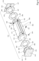
- FIG 3 shows a schematically indicated assembled cross-member 310 according to the invention.
- Figure 4 shows an exploded view of the cross-member in Figure 3 .
- the cross-member has an integrated fluid tank comprising an intermediate tank section 311 with open end portions 345, 348, where each open-end portion comprises a sealing flange 312, 313.
- Tank end caps 301, 302 attachable to seal opposite end portions of the intermediate tank section 311.
- Each end cap 301, 302 comprises an end cap sealing flange 314, 315 facing the corresponding tank sealing flange 312, 313 at opposite end portions of the intermediate tank section 311, wherein each tank end cap 301, 302 is provided with a mounting plate 316, 317 facing away from the intermediate tank section 311, which mounting plate 316, 317 is arranged to be attached to a frame rail on opposite sides of the vehicle.
- the intermediate tank section 311 and the tank end caps 301, 302 are joined by facing sealing flanges 312, 313, 314, 315 and intermediate sealing gaskets 326, 327 provided with a first interface 341, 342, 343, which first interface comprises a matching hole grid pattern arranged to orientate the facing flanges relative to each other (see Figure 6 ).
- the hole grid pattern can have a "poka-yoke" type feature to ensure that the facing flanges are mounted in a particular angular position relative to each other.
- a feature is an unsymmetrical hole offset on the sealing flanges and gaskets to align the intermediate tank section flanges 312, 313 with respect to the respective end cap flange 314, 315.
- FIG. 6 is a front view of one of the sealing flanges 312 on the intermediate tank section 311 in Figure 4 .
- the sealing flange 312 comprises six through holes on the same set pitch circle, wherein a first pair of holes 601, 602 are located at identical first angles ⁇ relative to a vertical axis X1 through the centre of the pitch circle.
- a second pair of holes 603, 604 are located at identical second angles ⁇ relative to the vertical axis X 1 .
- FIG. 6 further indicates that the first interface 341 of the respective flange can be provided with a suitable pattern in order to improve the sealing properties of the seal between the flanges and the sealing gaskets.
- the pattern comprises parallel ribs or splines.
- the invention is not limited to this pattern.
- the intermediate tank section 311 and the tank end caps 301, 302 are joined by removable fasteners, such as screw-and-nut fasteners.
- removable fasteners such as screw-and-nut fasteners.
- the joints used in this example are allowed to yield a predetermined amount when subjected to severe loads as the frame rails bend during operation of the vehicle. This allows the integrity of the tank to be maintained under loads which would cause welded joints to fracture or crack.
- the end cap flange 314, 315 and mounting plates 316, 317 are joined by structural support members 322, 323 extending from a respective outward facing surface of each end cap flange 314, 315 to a corresponding inward facing surface on each mounting plate 316, 317.
- the end cap flanges 314, 315, the mounting plates 316, 317 and the structural support members 322, 323 are welded together into individual units.
- a sealing gasket 326, 327 is provided between the respective tank sealing flanges 312, 313 and the end cap sealing flange 314, 315.
- the sealing flanges and their intermediate sealing gaskets are assembled using removable fasteners such as screw-and-nut fasteners 320, 321.
- the intermediate tank section 311 has a cylindrical internal cavity with a respective first circular opening 345, 348 at each end.
- Each first circular opening 345, 348 is matched by identical cylindrical openings 346, 347 in the respective end cap flanges 314, 315.
- the ends of the intermediate tank section 311 are sealed by the tank end caps 301, 302, which end caps comprise a hemi-spherical or part-hemispherical surface facing the intermediate tank section 311.
- the intermediate tank section 311 and the tank end caps form a closed cavity that can be pressurized or filled by a liquid.
- the mounting plates 316, 317 on the end caps have a second interface 318, 319 comprising a hole pattern arranged to match a frame rail hole grid pattern (not shown).
- the cross-member 310 can be re-positioned both in the longitudinal and the vertical direction, where allowed by the frame rail hole grid pattern.
- the cross-member 310 with its integrated tank is detachable and replaceable by fixing the mounting plates 316, 317 to the frame rails using removable fasteners such as bolted or screw-and-nut fasteners.
- the footprint of the mounting plate 316, 317 on the respective frame rail is reduced as the size of the mounting plate can be substantially the same as the cross-sectional area of the integrated tank.
- the intermediate tank section 311 in Figures 3 and 4 has an upper surface 351, a lower surface 353, a rear interface 352 and a front interface 354.
- the front and rear interfaces 352, 354 comprise a hole pattern 355 arranged to match a hole grid pattern on at least one auxiliary component.
- This arrangement allows the cross-member to be used as a support structure for a vehicle axle or wheel suspension component.
- the front/rear interfaces can be used for mounting one or more additional fluid tanks, e.g. tanks for compressed air, hydraulic fluids or gaseous/liquid fuels, such as LNG, CNG or diesel fuels.
- Energy storage units, such as battery packs, or fuel cell components can also be supported by one or more integrated tank cross-members.
- the intermediate tank section 311 is provided with a number of vales 330, 331, 332.
- the intermediate tank section 311 has a first valve 330 connected to a source of pneumatic pressure (not shown).
- the intermediate tank section 311 also has one supply valve 331, 332 at each end in order to supply adjacent component parts (not shown), such as air bellows and/or brakes, with compressed air.
- Figure 4 also indicates an optional valve 334 that allows the air tank shown in the figure to be connected to a further air tank.
- Figure 5 shows a schematically indicated, alternative vehicle frame 501 comprising an angled cross-member 510 with an integrated tank.
- Figure 5 shows a schematic indicated vehicle frame 501 with an alternative cross-member 510 according to the invention.
- Figure 5 shows a rear section of the vehicle frame 501, which frame comprises a first longitudinal frame rail 503, a parallel second longitudinal frame rail 504, at least one structural cross-member 505 (one shown), a rearmost cross-member 506, and a cross-member 510 with an integrated tank.
- the frame rails 503, 504 are substantially parallel to the longitudinal axis X of the vehicle frame 501.
- the number of cross-members with integrated tanks can be varied dependent on the size of the vehicle frame and the requirement for tanks and/or auxiliary components for the vehicle frame in question.
- the cross-member 510 has an integrated fluid tank comprising an intermediate tank section 511 comprises a sealing flange 512, 513 at opposite end portions of the intermediate tank section 511.
- Each end cap 505, 506 comprises an end cap sealing flange 314, 315 faces a corresponding tank sealing flange 512, 513 at opposite end portions of the intermediate tank section 511, wherein each tank end cap 505, 506 is provided with a mounting plate (not shown; see Fig.3 ) facing away from the intermediate tank section 511.
- the end cap flange 514, 515 and mounting plates are joined by structural support members 522, 523 extending from a respective outward facing surface of each end cap flange 514, 515 to a corresponding inward facing surface on each mounting plate.
- the mounting plates are arranged to be attached to a frame rail on opposite sides of the vehicle.
- the cross-member 510 shown in Figure 5 can retain all the component parts used in the cross-member 310 shown in Figure 3 , except for the structural support members 522, 523 which provide the desired angled arrangement of the cross-member 510.
- the embodiment of Figure 5 differs from the embodiment of Figure 2 in that the cross-member 510 is angled relative to a transverse axis Y located at right angles to the longitudinal axis X of the frame 501.
- the cross-member 510 is mounted at an acute angle ⁇ relative to a transverse axis Y. This acute angle is preferably selected to be 20° or less.
- An angled mounting of a cross-member with an integrated tank can be used in a position where a transverse arrangement cannot be fitted. This can be the case where one or more existing frame rail mounted components or axle parts are placed so that there is no space for a transverse cross-member or that the frame rail hole pattern is occupied or inaccessible.
Landscapes
- Engineering & Computer Science (AREA)
- Mechanical Engineering (AREA)
- Chemical & Material Sciences (AREA)
- Combustion & Propulsion (AREA)
- Transportation (AREA)
- Life Sciences & Earth Sciences (AREA)
- Sustainable Development (AREA)
- Sustainable Energy (AREA)
- Body Structure For Vehicles (AREA)
Description
- The invention relates to a vehicle frame arrangement, which frame arrangement comprises a detachable cross-member with an integrated tank.
- Conventional vehicle frames for heavy duty vehicles comprise two frame rails spaced from one another and secured to one another using cross-members. It is well known to suspend various components, such as fuel tanks, battery packs and compressed air tanks for heavy duty vehicles from the frame. These components may be bolted to the frame rails or cross members or supported on subassemblies which in turn are hung from or otherwise supported from the frame. In such vehicles the components and their support arrangements add weight to the vehicle, and in some applications take up valuable space.
-
US2010/327573 suggests a solution to the above problems, wherein an air tank and a cross-member is combined into a single component. A cylindrical tank section is welded onto a pair of back plates which can in turn be bolted to the frame. - One problem with the above solutions is that the tank section is welded directly onto the plates used for mounting. These welds will be subjected to severe loads as the frame rails bend during operation of the vehicle. This will eventually cause the welds to fail and the tank will begin to leak along failed weld sections. A further problem is that the suggested arrangement is welded to form a single component, so that the entire cross-member must be replaced upon failure. Finally, as the cylindrical tank section is welded directly onto the mounting plates, the bolts used for fixing the cross-member to the frame must be positioned outside the outer periphery of the tank. A problem with this arrangement is that the space required for mounting the cross-member onto the frame rails will be relatively large and can also limit the maximum diameter of tank.
- An object of the present invention is to provide an improved vehicle frame and cross member arrangement that addresses at least some of the above issues.
- According to a first aspect, the invention relates to a vehicle frame comprising first and second parallel, longitudinal frame rails and multiple cross-members connecting the frame rails. The vehicle frame is provided with at least one cross-member with an integrated fluid tank, instead of or in combination with conventional cross-members.
- A cross-member with an integrated fluid tank comprises an intermediate tank section with open end portions, where each open-end portion comprises a sealing flange, and tank end caps attachable to seal opposite end portions of the intermediate tank section. Each end cap comprises an end cap sealing flange facing a corresponding tank sealing flange at opposite end portions of the intermediate tank section, wherein each tank end cap is provided with a mounting plate facing away from the intermediate tank section, which mounting plate is arranged to be attached to a frame rail on opposite sides of the vehicle.
- The intermediate tank section and the tank end caps have facing sealing flanges with a first interface, which first interface comprises a matching hole grid pattern arranged to orientate the facing flanges relative to each other. The hole grid pattern can have a "poka-yoke" type feature to ensure that the facing flanges are mounted in a particular angular position relative to each other. One example of such a feature is an unsymmetrical hole offset on the sealing flanges to align the intermediate tank section flanges with respect to the respective end cap flange. This can be achieved by positioning holes arranged on a set pitch circle so that at least one hole is offset from an equidistant hole distribution around the pitch circle.
- Alternatively, the intermediate tank section and the tank end caps have facing flanges with an alternative first interface, which first interface comprises mating projections and recesses arranged on facing flanges. In this way, the facing flanges must be orientated in a particular angular position relative to each other in order to allow the flanges to be assembled.
- Further, the mounting plates on the end caps have a second interface comprising a hole pattern arranged to match a frame rail hole grid pattern. This allows the assembled cross-member to be located at any suitable position where the mounting plate interfaces line up with the frame rail hole grid pattern. If desired, the cross-member can be re-positioned both in the longitudinal and the vertical direction, where allowed by the frame rail hole grid pattern. According to a further example, a cross-member with an integrated tank can be made detachable and replaceable by fixing the mounting plates to the frame rails using removable fasteners such as bolted or screw-and-nut fasteners. In addition, as the mounting plates are separated from the tank end caps, the footprint of the mounting plate on the respective frame rail is reduced as the size of the mounting plate can be substantially the same as the cross-sectional area of the integrated tank.
- According to a further example, the intermediate tank section has a front and/or a rear interface comprising a hole pattern arranged to match a hole grid pattern on at least one auxiliary component. This arrangement allows the cross-member to be used as a support structure for a vehicle axle or wheel suspension component. Alternatively, the front/rear interfaces can be used for mounting one or more additional fluid tanks, e.g. tanks for compressed air, hydraulic fluids or gaseous/liquid fuels, such as LNG, CNG or diesel fuels. Energy storage units, such as battery packs, or fuel cell components can also be supported by one or more integrated tank cross-members.
- A cross-member with an integrated cross-member as described in the above examples is preferably mounted in the transverse direction of the frame, at right angles to the longitudinal frame rails. However, according to an alternative example, one or more such cross-members can be mounted at an acute angle relative to a transverse vertical plane through the frame rails. This acute angle is preferably selected to be 20° or less. An angled mounting of a cross-member with an integrated tank can be used in a position where a transverse arrangement cannot be fitted. This can be the case where one or more existing frame rail mounted components or axle parts are placed so that there is no space for a transverse cross-member or that the frame rail hole pattern is occupied or inaccessible.
- According to a second aspect, the invention relates to a vehicle comprising a vehicle frame as described above, wherein the vehicle frame comprises at least one cross-member with an integrated tank.
- Providing a vehicle frame with a cross-member according to the invention involves a number of advantages. The integration of a tank as described above utilizes a normally unoccupied area or volume between the longitudinal frame rails. This saves space and frees up space for other components, such as traction batteries, along the outer sides of the frame rails where tanks such as air tanks would normally be mounted.
- Further, a cross-member according to the invention is provided with mounting plates adapted to interface with available sections of hole grid patterns provided along the frame rails. This allows the assembled cross-member to be located at any suitable position where the mounting plate interfaces line up with the frame rail hole grid pattern. If desired, the cross-member can be positioned or re-positioned both in the longitudinal and the vertical direction of the frame rails, where this is allowed by the frame rail hole grid pattern. Also, by separating the end caps and the mounting plates a predetermined distance, the footprint of the cross-member on the frame rails is reduced. According to a further example, a cross-member with an integrated tank can be made detachable and replaceable by fixing the mounting plates to the frame rails using removable fasteners such as bolted or screw-and-nut fasteners.
- A cross-member according to the invention can also be provided with front and/or rear interfaces, comprising vertical surfaces with a suitable hole grid pattern in the same way as the frame rails. This arrangement allows the cross-member to be used as a support structure for a vehicle axle or wheel suspension component. Alternatively, the front/rear interfaces can be used for mounting one or more additional fluid tanks, e.g. tanks for compressed air, hydraulic fluids or gaseous/liquid fuels, such as LNG, CNG or diesel fuels.
- Further, the end caps with mounting plates provided for transverse mounting of the cross-member can be replaced by end caps having angled mounting plates. This allows the cross-member to be mounted at an angle relative to a transverse vertical plane through the frame rails. An angled mounting of a cross-member with an integrated tank can be used in a position where a transverse arrangement cannot be fitted. This can be the case where one or more existing frame rail mounted components or axle parts are placed so that there is no space for a transverse cross-member or that the frame rail hole pattern is occupied or inaccessible.
- With reference to the appended drawings, below follows a more detailed description of embodiments of the invention cited as examples. In the drawings:
- Figure 1
- shows a schematically indicated vehicle with a vehicle frame;
- Figure 2
- shows a schematic indicated vehicle frame with cross-members;
- Figure 3
- shows a schematically indicated cross-member;
- Figure 4
- shows an exploded view of the cross-member in
Figure 3 ; - Figure 5
- shows a schematically indicated vehicle frame comprising an angled cross-member; and
- Figure 6
- show a front view of an intermediate tank section in
Figure 4 . -
Figure 1 shows a schematically indicatedvehicle 100 with avehicle frame 101 according to the invention. Thevehicle 100 shown inFigure 1 is provided withfront wheels 102 on a steerable front axle andrear wheels 103 on a driven rear axle. Thevehicle 100 is further provided with propulsion means such as an internal combustion engine (ICE) 104 connected to atransmission 105, such as an automated manual transmission (AMT), for transmitting torque to a vehicle drive axle (not shown). TheICE 104 is connected to a radiator arrangement for cooling engine coolant and oil from theICE 104. Thevehicle frame 101 referred to can also be adapted for vehicles with alternative propulsion means, such as an electric motor. -
Figure 2 shows a schematic indicatedvehicle frame 201 withcross-members 210 according to the invention.Figure 2 shows a rear section of thevehicle frame 201, which frame comprises a firstlongitudinal frame rail 203, a parallel secondlongitudinal frame rail 204, at least one structural cross-member 205 (one shown), arearmost cross-member 206, and twocross-members 210 with integrated tanks. The number of cross-members with integrated tanks can be varied dependent on the size of the vehicle frame and the requirement for tanks and/or auxiliary components for the vehicle frame in question. -
Figure 3 shows a schematically indicated assembled cross-member 310 according to the invention.Figure 4 shows an exploded view of the cross-member inFigure 3 . The cross-member has an integrated fluid tank comprising anintermediate tank section 311 withopen end portions flange intermediate tank section 311. Eachend cap cap sealing flange tank sealing flange intermediate tank section 311, wherein eachtank end cap plate intermediate tank section 311, which mountingplate - The
intermediate tank section 311 and thetank end caps flanges intermediate sealing gaskets first interface Figure 6 ). The hole grid pattern can have a "poka-yoke" type feature to ensure that the facing flanges are mounted in a particular angular position relative to each other. One example of such a feature is an unsymmetrical hole offset on the sealing flanges and gaskets to align the intermediatetank section flanges end cap flange Figure 6 , one way of achieving this feature is to positioning holes arranged on a set pitch circle so that at least one hole is offset from an equidistant hole distribution around the pitch circle.Figure 6 is a front view of one of the sealingflanges 312 on theintermediate tank section 311 inFigure 4 . In this example, the sealingflange 312 comprises six through holes on the same set pitch circle, wherein a first pair ofholes holes Figure 6 further indicates that thefirst interface 341 of the respective flange can be provided with a suitable pattern in order to improve the sealing properties of the seal between the flanges and the sealing gaskets. In this example, the pattern comprises parallel ribs or splines. However, the invention is not limited to this pattern. - The
intermediate tank section 311 and thetank end caps - The
end cap flange plates structural support members end cap flange plate end cap flanges plates structural support members Figure 4 , a sealinggasket tank sealing flanges cap sealing flange nut fasteners - As schematically indicated in
Figure 4 , theintermediate tank section 311 has a cylindrical internal cavity with a respective firstcircular opening circular opening cylindrical openings end cap flanges intermediate tank section 311 are sealed by thetank end caps intermediate tank section 311. When assembled theintermediate tank section 311 and the tank end caps form a closed cavity that can be pressurized or filled by a liquid. - Further, the mounting
plates second interface plate interfaces plates plates tank end caps plate - The
intermediate tank section 311 inFigures 3 and4 has anupper surface 351, alower surface 353, arear interface 352 and afront interface 354. The front andrear interfaces hole pattern 355 arranged to match a hole grid pattern on at least one auxiliary component. This arrangement allows the cross-member to be used as a support structure for a vehicle axle or wheel suspension component. Alternatively, the front/rear interfaces can be used for mounting one or more additional fluid tanks, e.g. tanks for compressed air, hydraulic fluids or gaseous/liquid fuels, such as LNG, CNG or diesel fuels. Energy storage units, such as battery packs, or fuel cell components can also be supported by one or more integrated tank cross-members. - As shown in
Figure 3 and4 , theintermediate tank section 311 is provided with a number ofvales intermediate tank section 311 has afirst valve 330 connected to a source of pneumatic pressure (not shown). Theintermediate tank section 311 also has onesupply valve Figure 4 also indicates anoptional valve 334 that allows the air tank shown in the figure to be connected to a further air tank. -
Figure 5 shows a schematically indicated,alternative vehicle frame 501 comprising anangled cross-member 510 with an integrated tank.Figure 5 shows a schematic indicatedvehicle frame 501 with analternative cross-member 510 according to the invention.Figure 5 shows a rear section of thevehicle frame 501, which frame comprises a firstlongitudinal frame rail 503, a parallel secondlongitudinal frame rail 504, at least one structural cross-member 505 (one shown), arearmost cross-member 506, and a cross-member 510 with an integrated tank. The frame rails 503, 504 are substantially parallel to the longitudinal axis X of thevehicle frame 501. The number of cross-members with integrated tanks can be varied dependent on the size of the vehicle frame and the requirement for tanks and/or auxiliary components for the vehicle frame in question. - The cross-member 510 has an integrated fluid tank comprising an
intermediate tank section 511 comprises a sealingflange intermediate tank section 511. Eachend cap cap sealing flange tank sealing flange intermediate tank section 511, wherein eachtank end cap Fig.3 ) facing away from theintermediate tank section 511. Theend cap flange structural support members end cap flange - Compared to the embodiment of
Figure 3 , the cross-member 510 shown inFigure 5 can retain all the component parts used in the cross-member 310 shown inFigure 3 , except for thestructural support members - The embodiment of
Figure 5 differs from the embodiment ofFigure 2 in that the cross-member 510 is angled relative to a transverse axis Y located at right angles to the longitudinal axis X of theframe 501. The cross-member 510 is mounted at an acute angle α relative to a transverse axis Y. This acute angle is preferably selected to be 20° or less. An angled mounting of a cross-member with an integrated tank can be used in a position where a transverse arrangement cannot be fitted. This can be the case where one or more existing frame rail mounted components or axle parts are placed so that there is no space for a transverse cross-member or that the frame rail hole pattern is occupied or inaccessible. - The invention should not be deemed to be limited to the embodiments described above, but rather a number of further variants and modifications are conceivable within the scope of the following patent claims.
Claims (14)
- A vehicle frame (101; 201; 501) comprising first and second parallel frame rails (203, 204; 503, 504) and multiple cross-members (205, 206, 210) connecting the frame rails, wherein the vehicle frame has at least one cross-member with an integrated fluid tank (210; 310; 510), characterized in that the at least one cross-member and fluid tank (210; 310; 510) comprises:- an intermediate tank section (311; 511) with open end portions (345, 348), where each end portion comprises a sealing flange (312, 313);- tank end caps (301, 302; 505, 506) attachable to seal opposite end portions of the intermediate tank section (311; 511);wherein each end cap (301, 302; 505, 506) comprises an end cap sealing flange (314, 315) facing a corresponding tank sealing flange (312, 313) at opposite end portions (345, 348) of the intermediate tank (311; 511); andwherein each tank end cap (301, 302; 505, 506) is provided with a mounting plate (316, 317) facing away from the intermediate tank section (311; 511), which mounting plate is arranged to be attached to a frame rail (203, 204; 503, 504).
- The vehicle frame according to claim 1, wherein the intermediate tank section (311; 511) and the tank end caps (301, 302; 505, 506) have facing sealing flanges (312, 313; 314, 315) with a first interface (341, 343), which first interface comprises a matching hole grid pattern arranged to orientate the facing flanges relative to each other.
- The vehicle frame according to claim 2, wherein the first interface comprises a matching hole grid pattern an unsymmetrical hole offset on the facing flanges.
- The vehicle frame according to claim 1, wherein the intermediate tank section (311; 511) and the tank end caps (301, 302; 505, 506) have facing flanges with a first interface, which first interface comprises mating projections and recesses arranged to orientate the respective facing flanges relative to each other.
- The vehicle frame according to any one of claims 1-4, wherein the facing sealing flanges (312, 313; 314, 315) have sealing surfaces with vertical splines in contact with an intermediate sealing gasket.
- The vehicle frame according to any one of claims 1-5, wherein the mounting plates (316, 317) have a second interface (318, 319) comprising a hole pattern arranged to match a frame rail hole grid pattern (207).
- The vehicle frame according to any one of claims 1-6, wherein the integrated fluid tank is an air tank.
- The vehicle frame according to any one of claims 1-7, wherein the intermediate tank section (311; 511) has a front interface (354) comprising a hole pattern (355) arranged to match a hole grid pattern on at least one auxiliary component.
- The vehicle frame according to any one of claims 1-7, wherein the intermediate tank section (311; 511) has a rear interface (352) comprising a hole pattern arranged to match a hole grid pattern on at least one auxiliary component.
- The vehicle frame according to claim 8 or 9, wherein the auxiliary component is an additional fluid tank or a suspension component.
- The vehicle frame according to any one of the above claims 1-10, wherein the cross member (510) is mounted at an acute angle (α) relative to a transverse vertical plane through the frame rails.
- The vehicle frame according to claim 11, wherein the cross-member is mounted at an acute angle (α) that is less than 20°.
- The vehicle frame according to any one of the above claims 1-12, wherein the cross member is mounted to the frame rails by removable fasteners.
- Vehicle wherein the vehicle (100) comprises a vehicle frame according to claim 1.
Applications Claiming Priority (2)
| Application Number | Priority Date | Filing Date | Title |
|---|---|---|---|
| IN202041004355 | 2020-01-31 | ||
| PCT/EP2021/050507 WO2021151657A1 (en) | 2020-01-31 | 2021-01-13 | Vehicle frame and cross-member arrangement |
Publications (3)
| Publication Number | Publication Date |
|---|---|
| EP4096953A1 EP4096953A1 (en) | 2022-12-07 |
| EP4096953C0 EP4096953C0 (en) | 2024-05-22 |
| EP4096953B1 true EP4096953B1 (en) | 2024-05-22 |
Family
ID=74186693
Family Applications (1)
| Application Number | Title | Priority Date | Filing Date |
|---|---|---|---|
| EP21700546.1A Active EP4096953B1 (en) | 2020-01-31 | 2021-01-13 | Vehicle frame and cross-member arrangement |
Country Status (4)
| Country | Link |
|---|---|
| US (1) | US12269529B2 (en) |
| EP (1) | EP4096953B1 (en) |
| CN (1) | CN114901505A (en) |
| WO (1) | WO2021151657A1 (en) |
Families Citing this family (1)
| Publication number | Priority date | Publication date | Assignee | Title |
|---|---|---|---|---|
| WO2022269629A1 (en) * | 2021-06-21 | 2022-12-29 | Metalsa India Pvt. Ltd. | An improved modular air tank cross member |
Family Cites Families (12)
| Publication number | Priority date | Publication date | Assignee | Title |
|---|---|---|---|---|
| US20050062251A1 (en) * | 2003-09-22 | 2005-03-24 | Ramsey John E. | Vehicle frame having air tank cross member |
| US7503586B2 (en) | 2003-09-22 | 2009-03-17 | Hendrickson Usa, L.L.C. | Vehicle frame having air tank cross member |
| US7198298B2 (en) * | 2003-10-15 | 2007-04-03 | Hendrickson Usa, L L C | Movable subframe for semi-trailers |
| US8146948B2 (en) | 2009-06-24 | 2012-04-03 | International Truck Intellectual Property Company, Llc | Structural air tank crossmember |
| DE202013004660U1 (en) * | 2013-05-16 | 2013-05-29 | Helmut Fliegl | Vehicle trailer with integrated air tank |
| CN105905995B (en) * | 2016-05-15 | 2019-05-03 | 宜兴市凌泰环保设备有限公司 | High-efficiency automatic control is horizontal to determine pole electric flocculation decontamination apparatus |
| DE102017106028A1 (en) * | 2017-03-21 | 2018-09-27 | Scania Cv Ab | Shaping a memory container integrated in a structural component of a vehicle frame |
| DE102017106024A1 (en) | 2017-03-21 | 2018-09-27 | Scania Cv Ab | Structural component of a vehicle frame with an integrated storage container |
| US10000328B1 (en) * | 2017-05-11 | 2018-06-19 | Robson Forensic, Inc. | Vehicle fuel tank for improved crashworthiness |
| JP2018203091A (en) | 2017-06-06 | 2018-12-27 | いすゞ自動車株式会社 | Tank and cross member |
| CN208344338U (en) * | 2018-06-28 | 2019-01-08 | 北京长城华冠汽车技术开发有限公司 | Front beam and vacuum tank integrating device, vehicle frame and automobile |
| CN110228526A (en) * | 2019-05-14 | 2019-09-13 | 东风商用车有限公司 | A kind of lightweight tractor chassis assembly |
-
2021
- 2021-01-13 EP EP21700546.1A patent/EP4096953B1/en active Active
- 2021-01-13 CN CN202180007564.6A patent/CN114901505A/en active Pending
- 2021-01-13 WO PCT/EP2021/050507 patent/WO2021151657A1/en not_active Ceased
- 2021-01-13 US US17/785,685 patent/US12269529B2/en active Active
Also Published As
| Publication number | Publication date |
|---|---|
| US12269529B2 (en) | 2025-04-08 |
| WO2021151657A1 (en) | 2021-08-05 |
| EP4096953C0 (en) | 2024-05-22 |
| US20230052999A1 (en) | 2023-02-16 |
| EP4096953A1 (en) | 2022-12-07 |
| CN114901505A (en) | 2022-08-12 |
Similar Documents
| Publication | Publication Date | Title |
|---|---|---|
| KR102089827B1 (en) | Work vehicle | |
| US7658262B2 (en) | Axle assembly | |
| US12222069B2 (en) | High-pressure hydrogen tank | |
| US10330399B2 (en) | Heat exchanger and heat exchanger tank | |
| MX2011006218A (en) | Tie-plate and frame hanger of a suspension assembly. | |
| EP4096953B1 (en) | Vehicle frame and cross-member arrangement | |
| CN101480918A (en) | Mounting arrangement for a retaining strap of a gas tank holding device | |
| KR19990044504A (en) | Fluid storage container with double chamber | |
| KR20220016215A (en) | fuel tank | |
| CN220912076U (en) | Multi-connected heat exchanger without intermediate pipe box | |
| CN220809669U (en) | Frame assembly for electric motorcycle and electric motorcycle | |
| CN219300507U (en) | Integrated mounting structure of gas holder and solenoid valve and air suspension thereof | |
| CN218200156U (en) | Anti-surge device in tank body of liquid tank truck | |
| CN223100453U (en) | Plastic high pressure fuel tank assembly | |
| CN222940057U (en) | Sealed connection structure and battery pack | |
| JP2006038154A (en) | Pressure vessel | |
| CN222208435U (en) | Hydraulic oil tank connecting structure of off-road vehicle | |
| US12617262B2 (en) | Vehicle provided with a power storage system | |
| CN218805004U (en) | Axle housing for engineering machinery | |
| CN221004104U (en) | Pipeline joint module and vehicle with same | |
| CN121133765A (en) | A bogie and a tram | |
| CN222136352U (en) | Bent tube beam and vehicle | |
| CN223494593U (en) | Frame assembly and vehicle | |
| US20260092682A1 (en) | Pressure vessel unit | |
| US20240140187A1 (en) | Vehicle provided with a power storage system |
Legal Events
| Date | Code | Title | Description |
|---|---|---|---|
| STAA | Information on the status of an ep patent application or granted ep patent |
Free format text: STATUS: UNKNOWN |
|
| STAA | Information on the status of an ep patent application or granted ep patent |
Free format text: STATUS: THE INTERNATIONAL PUBLICATION HAS BEEN MADE |
|
| PUAI | Public reference made under article 153(3) epc to a published international application that has entered the european phase |
Free format text: ORIGINAL CODE: 0009012 |
|
| STAA | Information on the status of an ep patent application or granted ep patent |
Free format text: STATUS: REQUEST FOR EXAMINATION WAS MADE |
|
| 17P | Request for examination filed |
Effective date: 20220829 |
|
| AK | Designated contracting states |
Kind code of ref document: A1 Designated state(s): AL AT BE BG CH CY CZ DE DK EE ES FI FR GB GR HR HU IE IS IT LI LT LU LV MC MK MT NL NO PL PT RO RS SE SI SK SM TR |
|
| DAV | Request for validation of the european patent (deleted) | ||
| DAX | Request for extension of the european patent (deleted) | ||
| RIN1 | Information on inventor provided before grant (corrected) |
Inventor name: RAMABHADRAIAH, SHREEHARSHA, AKKUR Inventor name: RAMEGOWDA, RASANJAYA, ANKANAHALLI |
|
| GRAP | Despatch of communication of intention to grant a patent |
Free format text: ORIGINAL CODE: EPIDOSNIGR1 |
|
| STAA | Information on the status of an ep patent application or granted ep patent |
Free format text: STATUS: GRANT OF PATENT IS INTENDED |
|
| INTG | Intention to grant announced |
Effective date: 20231214 |
|
| GRAS | Grant fee paid |
Free format text: ORIGINAL CODE: EPIDOSNIGR3 |
|
| GRAA | (expected) grant |
Free format text: ORIGINAL CODE: 0009210 |
|
| STAA | Information on the status of an ep patent application or granted ep patent |
Free format text: STATUS: THE PATENT HAS BEEN GRANTED |
|
| RIN1 | Information on inventor provided before grant (corrected) |
Inventor name: RAMABHADRAIAH, SHREEHARSHA, AKKUR Inventor name: RAMEGOWDA, RASANJAYA, ANKANAHALLI |
|
| AK | Designated contracting states |
Kind code of ref document: B1 Designated state(s): AL AT BE BG CH CY CZ DE DK EE ES FI FR GB GR HR HU IE IS IT LI LT LU LV MC MK MT NL NO PL PT RO RS SE SI SK SM TR |
|
| REG | Reference to a national code |
Ref country code: GB Ref legal event code: FG4D |
|
| REG | Reference to a national code |
Ref country code: CH Ref legal event code: EP |
|
| REG | Reference to a national code |
Ref country code: DE Ref legal event code: R096 Ref document number: 602021013549 Country of ref document: DE |
|
| REG | Reference to a national code |
Ref country code: IE Ref legal event code: FG4D |
|
| U01 | Request for unitary effect filed |
Effective date: 20240619 |
|
| U07 | Unitary effect registered |
Designated state(s): AT BE BG DE DK EE FI FR IT LT LU LV MT NL PT SE SI Effective date: 20240627 |
|
| PG25 | Lapsed in a contracting state [announced via postgrant information from national office to epo] |
Ref country code: IS Free format text: LAPSE BECAUSE OF FAILURE TO SUBMIT A TRANSLATION OF THE DESCRIPTION OR TO PAY THE FEE WITHIN THE PRESCRIBED TIME-LIMIT Effective date: 20240922 |
|
| PG25 | Lapsed in a contracting state [announced via postgrant information from national office to epo] |
Ref country code: HR Free format text: LAPSE BECAUSE OF FAILURE TO SUBMIT A TRANSLATION OF THE DESCRIPTION OR TO PAY THE FEE WITHIN THE PRESCRIBED TIME-LIMIT Effective date: 20240522 |
|
| PG25 | Lapsed in a contracting state [announced via postgrant information from national office to epo] |
Ref country code: GR Free format text: LAPSE BECAUSE OF FAILURE TO SUBMIT A TRANSLATION OF THE DESCRIPTION OR TO PAY THE FEE WITHIN THE PRESCRIBED TIME-LIMIT Effective date: 20240823 |
|
| PG25 | Lapsed in a contracting state [announced via postgrant information from national office to epo] |
Ref country code: ES Free format text: LAPSE BECAUSE OF FAILURE TO SUBMIT A TRANSLATION OF THE DESCRIPTION OR TO PAY THE FEE WITHIN THE PRESCRIBED TIME-LIMIT Effective date: 20240522 |
|
| PG25 | Lapsed in a contracting state [announced via postgrant information from national office to epo] |
Ref country code: PL Free format text: LAPSE BECAUSE OF FAILURE TO SUBMIT A TRANSLATION OF THE DESCRIPTION OR TO PAY THE FEE WITHIN THE PRESCRIBED TIME-LIMIT Effective date: 20240522 |
|
| PG25 | Lapsed in a contracting state [announced via postgrant information from national office to epo] |
Ref country code: PL Free format text: LAPSE BECAUSE OF FAILURE TO SUBMIT A TRANSLATION OF THE DESCRIPTION OR TO PAY THE FEE WITHIN THE PRESCRIBED TIME-LIMIT Effective date: 20240522 Ref country code: NO Free format text: LAPSE BECAUSE OF FAILURE TO SUBMIT A TRANSLATION OF THE DESCRIPTION OR TO PAY THE FEE WITHIN THE PRESCRIBED TIME-LIMIT Effective date: 20240822 Ref country code: IS Free format text: LAPSE BECAUSE OF FAILURE TO SUBMIT A TRANSLATION OF THE DESCRIPTION OR TO PAY THE FEE WITHIN THE PRESCRIBED TIME-LIMIT Effective date: 20240922 Ref country code: HR Free format text: LAPSE BECAUSE OF FAILURE TO SUBMIT A TRANSLATION OF THE DESCRIPTION OR TO PAY THE FEE WITHIN THE PRESCRIBED TIME-LIMIT Effective date: 20240522 Ref country code: GR Free format text: LAPSE BECAUSE OF FAILURE TO SUBMIT A TRANSLATION OF THE DESCRIPTION OR TO PAY THE FEE WITHIN THE PRESCRIBED TIME-LIMIT Effective date: 20240823 Ref country code: ES Free format text: LAPSE BECAUSE OF FAILURE TO SUBMIT A TRANSLATION OF THE DESCRIPTION OR TO PAY THE FEE WITHIN THE PRESCRIBED TIME-LIMIT Effective date: 20240522 Ref country code: RS Free format text: LAPSE BECAUSE OF FAILURE TO SUBMIT A TRANSLATION OF THE DESCRIPTION OR TO PAY THE FEE WITHIN THE PRESCRIBED TIME-LIMIT Effective date: 20240822 |
|
| PG25 | Lapsed in a contracting state [announced via postgrant information from national office to epo] |
Ref country code: CZ Free format text: LAPSE BECAUSE OF FAILURE TO SUBMIT A TRANSLATION OF THE DESCRIPTION OR TO PAY THE FEE WITHIN THE PRESCRIBED TIME-LIMIT Effective date: 20240522 |
|
| PG25 | Lapsed in a contracting state [announced via postgrant information from national office to epo] |
Ref country code: SK Free format text: LAPSE BECAUSE OF FAILURE TO SUBMIT A TRANSLATION OF THE DESCRIPTION OR TO PAY THE FEE WITHIN THE PRESCRIBED TIME-LIMIT Effective date: 20240522 Ref country code: RO Free format text: LAPSE BECAUSE OF FAILURE TO SUBMIT A TRANSLATION OF THE DESCRIPTION OR TO PAY THE FEE WITHIN THE PRESCRIBED TIME-LIMIT Effective date: 20240522 |
|
| PG25 | Lapsed in a contracting state [announced via postgrant information from national office to epo] |
Ref country code: SK Free format text: LAPSE BECAUSE OF FAILURE TO SUBMIT A TRANSLATION OF THE DESCRIPTION OR TO PAY THE FEE WITHIN THE PRESCRIBED TIME-LIMIT Effective date: 20240522 Ref country code: RO Free format text: LAPSE BECAUSE OF FAILURE TO SUBMIT A TRANSLATION OF THE DESCRIPTION OR TO PAY THE FEE WITHIN THE PRESCRIBED TIME-LIMIT Effective date: 20240522 Ref country code: CZ Free format text: LAPSE BECAUSE OF FAILURE TO SUBMIT A TRANSLATION OF THE DESCRIPTION OR TO PAY THE FEE WITHIN THE PRESCRIBED TIME-LIMIT Effective date: 20240522 |
|
| REG | Reference to a national code |
Ref country code: DE Ref legal event code: R097 Ref document number: 602021013549 Country of ref document: DE |
|
| U20 | Renewal fee for the european patent with unitary effect paid |
Year of fee payment: 5 Effective date: 20250127 |
|
| PLBE | No opposition filed within time limit |
Free format text: ORIGINAL CODE: 0009261 |
|
| STAA | Information on the status of an ep patent application or granted ep patent |
Free format text: STATUS: NO OPPOSITION FILED WITHIN TIME LIMIT |
|
| 26N | No opposition filed |
Effective date: 20250225 |
|
| REG | Reference to a national code |
Ref country code: CH Ref legal event code: PL |
|
| PG25 | Lapsed in a contracting state [announced via postgrant information from national office to epo] |
Ref country code: MC Free format text: LAPSE BECAUSE OF FAILURE TO SUBMIT A TRANSLATION OF THE DESCRIPTION OR TO PAY THE FEE WITHIN THE PRESCRIBED TIME-LIMIT Effective date: 20240522 |
|
| GBPC | Gb: european patent ceased through non-payment of renewal fee |
Effective date: 20250113 |
|
| PG25 | Lapsed in a contracting state [announced via postgrant information from national office to epo] |
Ref country code: GB Free format text: LAPSE BECAUSE OF NON-PAYMENT OF DUE FEES Effective date: 20250113 |
|
| PG25 | Lapsed in a contracting state [announced via postgrant information from national office to epo] |
Ref country code: CH Free format text: LAPSE BECAUSE OF NON-PAYMENT OF DUE FEES Effective date: 20250131 |
|
| PG25 | Lapsed in a contracting state [announced via postgrant information from national office to epo] |
Ref country code: IE Free format text: LAPSE BECAUSE OF NON-PAYMENT OF DUE FEES Effective date: 20250113 |