EP4096563B1 - Proximity detection for a surgical light - Google Patents
Proximity detection for a surgical light Download PDFInfo
- Publication number
- EP4096563B1 EP4096563B1 EP21705748.8A EP21705748A EP4096563B1 EP 4096563 B1 EP4096563 B1 EP 4096563B1 EP 21705748 A EP21705748 A EP 21705748A EP 4096563 B1 EP4096563 B1 EP 4096563B1
- Authority
- EP
- European Patent Office
- Prior art keywords
- housing
- distance sensors
- distance
- light head
- distance sensor
- Prior art date
- Legal status (The legal status is an assumption and is not a legal conclusion. Google has not performed a legal analysis and makes no representation as to the accuracy of the status listed.)
- Active
Links
Images







Classifications
-
- A—HUMAN NECESSITIES
- A61—MEDICAL OR VETERINARY SCIENCE; HYGIENE
- A61B—DIAGNOSIS; SURGERY; IDENTIFICATION
- A61B90/00—Instruments, implements or accessories specially adapted for surgery or diagnosis and not covered by any of the groups A61B1/00 - A61B50/00, e.g. for luxation treatment or for protecting wound edges
- A61B90/30—Devices for illuminating a surgical field, the devices having an interrelation with other surgical devices or with a surgical procedure
-
- F—MECHANICAL ENGINEERING; LIGHTING; HEATING; WEAPONS; BLASTING
- F21—LIGHTING
- F21V—FUNCTIONAL FEATURES OR DETAILS OF LIGHTING DEVICES OR SYSTEMS THEREOF; STRUCTURAL COMBINATIONS OF LIGHTING DEVICES WITH OTHER ARTICLES, NOT OTHERWISE PROVIDED FOR
- F21V23/00—Arrangement of electric circuit elements in or on lighting devices
- F21V23/04—Arrangement of electric circuit elements in or on lighting devices the elements being switches
- F21V23/0442—Arrangement of electric circuit elements in or on lighting devices the elements being switches activated by means of a sensor, e.g. motion or photodetectors
-
- F—MECHANICAL ENGINEERING; LIGHTING; HEATING; WEAPONS; BLASTING
- F21—LIGHTING
- F21V—FUNCTIONAL FEATURES OR DETAILS OF LIGHTING DEVICES OR SYSTEMS THEREOF; STRUCTURAL COMBINATIONS OF LIGHTING DEVICES WITH OTHER ARTICLES, NOT OTHERWISE PROVIDED FOR
- F21V23/00—Arrangement of electric circuit elements in or on lighting devices
- F21V23/04—Arrangement of electric circuit elements in or on lighting devices the elements being switches
- F21V23/0442—Arrangement of electric circuit elements in or on lighting devices the elements being switches activated by means of a sensor, e.g. motion or photodetectors
- F21V23/0471—Arrangement of electric circuit elements in or on lighting devices the elements being switches activated by means of a sensor, e.g. motion or photodetectors the sensor detecting the proximity, the presence or the movement of an object or a person
-
- G—PHYSICS
- G01—MEASURING; TESTING
- G01S—RADIO DIRECTION-FINDING; RADIO NAVIGATION; DETERMINING DISTANCE OR VELOCITY BY USE OF RADIO WAVES; LOCATING OR PRESENCE-DETECTING BY USE OF THE REFLECTION OR RERADIATION OF RADIO WAVES; ANALOGOUS ARRANGEMENTS USING OTHER WAVES
- G01S17/00—Systems using the reflection or reradiation of electromagnetic waves other than radio waves, e.g. lidar systems
- G01S17/88—Lidar systems specially adapted for specific applications
-
- A—HUMAN NECESSITIES
- A61—MEDICAL OR VETERINARY SCIENCE; HYGIENE
- A61B—DIAGNOSIS; SURGERY; IDENTIFICATION
- A61B17/00—Surgical instruments, devices or methods
- A61B2017/00681—Aspects not otherwise provided for
- A61B2017/00738—Aspects not otherwise provided for part of the tool being offset with respect to a main axis, e.g. for better view for the surgeon
-
- A—HUMAN NECESSITIES
- A61—MEDICAL OR VETERINARY SCIENCE; HYGIENE
- A61B—DIAGNOSIS; SURGERY; IDENTIFICATION
- A61B90/00—Instruments, implements or accessories specially adapted for surgery or diagnosis and not covered by any of the groups A61B1/00 - A61B50/00, e.g. for luxation treatment or for protecting wound edges
- A61B90/06—Measuring instruments not otherwise provided for
- A61B2090/061—Measuring instruments not otherwise provided for for measuring dimensions, e.g. length
-
- A—HUMAN NECESSITIES
- A61—MEDICAL OR VETERINARY SCIENCE; HYGIENE
- A61B—DIAGNOSIS; SURGERY; IDENTIFICATION
- A61B90/00—Instruments, implements or accessories specially adapted for surgery or diagnosis and not covered by any of the groups A61B1/00 - A61B50/00, e.g. for luxation treatment or for protecting wound edges
- A61B90/08—Accessories or related features not otherwise provided for
- A61B2090/0818—Redundant systems, e.g. using two independent measuring systems and comparing the signals
-
- A—HUMAN NECESSITIES
- A61—MEDICAL OR VETERINARY SCIENCE; HYGIENE
- A61B—DIAGNOSIS; SURGERY; IDENTIFICATION
- A61B2562/00—Details of sensors; Constructional details of sensor housings or probes; Accessories for sensors
- A61B2562/02—Details of sensors specially adapted for in-vivo measurements
- A61B2562/0257—Proximity sensors
-
- A—HUMAN NECESSITIES
- A61—MEDICAL OR VETERINARY SCIENCE; HYGIENE
- A61B—DIAGNOSIS; SURGERY; IDENTIFICATION
- A61B90/00—Instruments, implements or accessories specially adapted for surgery or diagnosis and not covered by any of the groups A61B1/00 - A61B50/00, e.g. for luxation treatment or for protecting wound edges
- A61B90/30—Devices for illuminating a surgical field, the devices having an interrelation with other surgical devices or with a surgical procedure
- A61B90/35—Supports therefor
-
- F—MECHANICAL ENGINEERING; LIGHTING; HEATING; WEAPONS; BLASTING
- F21—LIGHTING
- F21W—INDEXING SCHEME ASSOCIATED WITH SUBCLASSES F21K, F21L, F21S and F21V, RELATING TO USES OR APPLICATIONS OF LIGHTING DEVICES OR SYSTEMS
- F21W2131/00—Use or application of lighting devices or systems not provided for in codes F21W2102/00-F21W2121/00
- F21W2131/20—Lighting for medical use
- F21W2131/205—Lighting for medical use for operating theatres
-
- F—MECHANICAL ENGINEERING; LIGHTING; HEATING; WEAPONS; BLASTING
- F21—LIGHTING
- F21Y—INDEXING SCHEME ASSOCIATED WITH SUBCLASSES F21K, F21L, F21S and F21V, RELATING TO THE FORM OR THE KIND OF THE LIGHT SOURCES OR OF THE COLOUR OF THE LIGHT EMITTED
- F21Y2115/00—Light-generating elements of semiconductor light sources
- F21Y2115/10—Light-emitting diodes [LED]
-
- G—PHYSICS
- G01—MEASURING; TESTING
- G01C—MEASURING DISTANCES, LEVELS OR BEARINGS; SURVEYING; NAVIGATION; GYROSCOPIC INSTRUMENTS; PHOTOGRAMMETRY OR VIDEOGRAMMETRY
- G01C3/00—Measuring distances in line of sight; Optical rangefinders
-
- G—PHYSICS
- G01—MEASURING; TESTING
- G01S—RADIO DIRECTION-FINDING; RADIO NAVIGATION; DETERMINING DISTANCE OR VELOCITY BY USE OF RADIO WAVES; LOCATING OR PRESENCE-DETECTING BY USE OF THE REFLECTION OR RERADIATION OF RADIO WAVES; ANALOGOUS ARRANGEMENTS USING OTHER WAVES
- G01S17/00—Systems using the reflection or reradiation of electromagnetic waves other than radio waves, e.g. lidar systems
- G01S17/02—Systems using the reflection of electromagnetic waves other than radio waves
- G01S17/06—Systems determining position data of a target
- G01S17/08—Systems determining position data of a target for measuring distance only
-
- G—PHYSICS
- G01—MEASURING; TESTING
- G01S—RADIO DIRECTION-FINDING; RADIO NAVIGATION; DETERMINING DISTANCE OR VELOCITY BY USE OF RADIO WAVES; LOCATING OR PRESENCE-DETECTING BY USE OF THE REFLECTION OR RERADIATION OF RADIO WAVES; ANALOGOUS ARRANGEMENTS USING OTHER WAVES
- G01S17/00—Systems using the reflection or reradiation of electromagnetic waves other than radio waves, e.g. lidar systems
- G01S17/87—Combinations of systems using electromagnetic waves other than radio waves
Definitions
- This application relates generally to a surgical light, and more particularly to a system for aiming and controlling a light output and proximity detection of surgical lights.
- Surgical lights are used in operating rooms to provide increased light to a specific area of the room.
- the surgical light may be positioned in an operating room and configured to provide increased light to a specific area of a surgical patient.
- the light may include a light housing containing a light source and a distance sensor that measures a distance from the light housing to the object to be illuminated, such that attributes of the light emitted from the light housing may be altered based on the distance detected by the distance sensor.
- conventional sensor systems may be susceptible to blockage that results in inaccurate measurements. For example, a head of a surgeon or other medical professional may block the sensor and consequently cause inaccurate distance measurements.
- US2015/208478 relates to a method for improving the illumination of an illuminated area, especially an operating area, of an illuminating device with at least two light modules.
- the method includes the emission of an illuminant characteristic of the light module with a preset amplitude from each light module.
- the reflected amplitudes of all characteristic light types are detected.
- the detected amplitudes for each light module are compared.
- the light intensity of at least one light module is varied on the basis of the comparison of the detected amplitudes for each light module.
- US9638406 relates to an energy-saving device of surgical light including a suspension or support system.
- CN102252216 relates to a shadow-less lighting lamp with a brightness compensation mechanism.
- US2018/209623 relates to a handle device for a surgical light.
- the handle device may include a grip element which is prepared for being arranged on a lamp holding body of the surgical light and which forms a grip surface at an outer area.
- a sensor module is detachably connected to the grip element, with the sensor module including at least one distance sensor which is designed for detecting a position of an object.
- the present application further includes a surgical light including such a handle device.
- US2017/0030573 relates to surgical lights and systems and method for maximizing the output of surgical lights by measuring with a distance sensor the distance from a light housing to an object to be illuminated and altering attributes of the emitted light depending on the measured distance.
- Embodiments of the invention may include one or more of the following additional features separately or in combination.
- the plurality of distance sensors may be mounted along a periphery of the housing in a spaced relationship relative to each other.
- the plurality of distance sensors may be evenly spaced.
- the plurality of distance sensors may be obliquely angled relative to a center line of focus of the surgical light head.
- the plurality of distance sensors may be obliquely angled relative to the center line of focus by an angle that is between 0.5 and 20 degrees.
- the surgical light head may further include an annular shape first lens that has a rotation axis, wherein the housing includes a housing cover including a cavity within which the annular shape first lens is rotatable about the rotation axis, wherein the housing cover includes a second lens, and wherein the outer distance sensors are arranged radially outwardly relative to the annular shape first lens and the second lens.
- the field of views may be defined by cones having an opening angle that is between 5 and 40 degrees.
- the plurality of distance sensors may include between five and ten distance sensors that are separate and spaced about the housing.
- the housing may define a plurality of seats configured for supporting the plurality of distance sensors.
- the seats may be obliquely angled toward a center line of focus of the surgical light head.
- the plurality of seats may be molded with the housing as a single monolithic component.
- the plurality of seats may include a single inner seat formed proximate the center line of focus and a plurality of outer seats that are formed on a periphery of the housing and radially spaced from the inner seat.
- the surgical light head may include a plurality of distance sensor assemblies that each include a corresponding one of the plurality of distance sensors and a printed circuit board assembly including an electrical interface communicatively coupled between the housing and the corresponding one of the plurality of distance sensors.
- Each of the plurality of distance sensor assemblies may include an optical component that covers the corresponding one of the plurality of distance sensors.
- the optical component may be sealed to the housing and coupled to the printed circuit board assembly.
- the corresponding one of the plurality of distance sensors may be configured to transmit and receive distance sensing signals through the optical component.
- the surgical light head may include an adhesive layer disposed between the optical component and the housing.
- the printed circuit board assembly and the optical component may be adhered by an acrylate adhesive material.
- the distance sensor and the optical component may define an air gap therebetween.
- the surgical light head may include a plurality of locating posts formed on the housing that are engageable with the optical component.
- the plurality of locating posts may be integrally formed with the housing as a single monolithic component.
- the locating posts may have a tapered shape.
- the plurality of distance sensors may be infrared distance sensors.
- a surgical light head includes a housing defining a center line of focus of the surgical light head, a plurality of distance sensors, and a plurality of tilted seats formed on the housing and configured for supporting the plurality of distance sensors.
- the plurality of tilted seats are obliquely angled toward the center line of focus.
- the plurality of tilted seats may be molded with the housing as a single monolithic component.
- the plurality of tilted seats may include a single inner seat formed proximate the center line of focus and a plurality of outer seats that are formed on a periphery of the housing and radially spaced from the inner seat.
- the surgical light head may include an annular shape first lens that has a rotation axis.
- the housing may include a housing cover including a cavity within which the annular shape first lens is rotatable about the rotation axis, wherein the housing cover includes a second lens, and the outer seats may be arranged radially outwardly relative to the annular shape first lens and the second lens.
- the plurality of tilted seats may be obliquely angled relative to the center line of focus by an angle that is between 0.5 and 20 degrees.
- the surgical light head may include a plurality of distance sensor assemblies that each include a corresponding one of the plurality of distance sensors and a printed circuit board assembly including an electrical interface communicatively coupled between the housing and the corresponding one of the plurality of distance sensors.
- Each of the plurality of distance sensor assemblies may include an optical component that covers the corresponding one of the plurality of distance sensors.
- the optical component may be matingly engageable against a corresponding one of the tilted seats and coupled to the printed circuit board assembly and the corresponding one of the plurality of distance sensors may be configured to transmit and receive distance sensing signals through the optical component.
- the surgical light head may include an adhesive layer disposed between the optical component and the corresponding one of the tilted seats.
- the printed circuit board assembly and the optical component may be adhered by an acrylate adhesive material.
- the surgical light head may include a plurality of locating posts that are formed on the plurality of tilted seats and engageable with a corresponding one of the plurality of distance sensor assemblies.
- the plurality of locating posts may be integrally formed with the housing as a single monolithic component.
- the plurality of distance sensors may be infrared distance sensors.
- the surgical light head may include a plurality of light emitting elements arranged in the housing and configured to direct light at a target region of interest that defines the center line of focus.
- the plurality of distance sensors may be obliquely angled toward the center line of focus when seated in the tilted seats, whereby at least two of the distance sensors have field of views that overlap to define a common detection region of interest.
- the common detection region of interest may at least partially overlap with the target region of interest.
- the plurality of distance sensors may be mounted along a periphery of the housing in a spaced relationship relative to each other.
- the plurality of distance sensors may be evenly spaced.
- the plurality of distance sensors may include a single inner distance sensor and a plurality of outer distance sensors that are radially spaced relative to the inner distance sensor.
- the field of views may be defined by cones having an opening angle that is between 5 and 40 degrees.
- the plurality of distance sensors may include between five and ten distance sensors that are separate and spaced about the housing.
- a surgical light head includes a housing, and a plurality of distance sensor assemblies integrated into the housing.
- Each of the plurality of distance sensor assemblies includes a distance sensor, a printed circuit board assembly having an electrical interface communicatively coupled between the housing and the distance sensor, and an optical component that covers the distance sensor, with the optical component being sealed to the housing and coupled to the printed circuit board assembly.
- the distance sensor is configured to transmit and receive distance sensing signals through the optical component.
- the surgical light head may include an adhesive layer disposed between the optical component and the housing.
- the printed circuit board assembly and the optical component may be adhered by an acrylate adhesive material.
- the distance sensor and the optical component may define an air gap therebetween.
- the housing may define a plurality of tilted seats configured for supporting the plurality of distance sensor assemblies, with the tilted seats being obliquely angled toward a center line of focus of the surgical light head.
- the plurality of tilted seats may be molded with the housing as a single monolithic component.
- the plurality of tilted seats may include a single inner seat formed proximate the center line of focus and a plurality of outer seats that are formed on a periphery of the housing and radially spaced from the inner seat.
- the surgical light head may include a plurality of locating posts formed on the tilted seats that are engageable with the optical component.
- the locating posts may protrude from a corresponding one of the plurality of tilted seats and have a tapered shape that tapers in a protrusion direction away from the corresponding one of the plurality of tilted seats.
- the surgical light head may include a plurality of light emitting elements arranged in the housing and configured to direct light at a target region of interest, with at least two of the distance sensor assemblies having field of views that overlap to define a common detection region of interest.
- the common detection region of interest may at least partially overlaps with the target region of interest.
- the plurality of distance sensor assemblies may be mounted along a periphery of the housing in a spaced relationship relative to each other.
- the surgical light head may include an annular shape first lens that has a rotation axis, with the housing including a housing cover including a cavity within which the annular shape first lens is rotatable about the rotation axis.
- the housing cover may include a second lens, and the outer distance sensor assemblies may be arranged radially outwardly relative to the annular shape first lens and the second lens.
- the plurality of distance sensor assemblies may be evenly spaced.
- the plurality of distance sensor assemblies may be obliquely angled relative to a center line of focus of the surgical light head.
- the plurality of distance sensor assemblies may be obliquely angled relative to the center line of focus by an angle that is between 0.5 and 20 degrees.
- the plurality of distance sensor assemblies may include between five and ten distance sensor assemblies that are separate and spaced about the housing.
- a method of proximity detecting for a surgical light head includes arranging a plurality of light emitting elements in a housing to direct light at a target region of interest, and arranging at least two distance sensors to have field of views that overlap to define a common detection region of interest.
- the common detection region of interest at least partially overlaps with the target region of interest.
- Arranging the at least two distance sensors may include angling the at least two distance sensors toward a center line of focus of the surgical light head.
- the method may include molding a housing having a plurality of tilted seats as a single monolithic component, with the plurality of tilted seats being obliquely angled toward the center line of focus, and arranging the plurality of distance sensors against the plurality of tilted seats to position the plurality of distance sensors.
- the method may include communicatively coupling the housing and one of the plurality of distance sensors with a printed circuit board assembly, mounting the printed circuit board assembly to an optical component, covering the distance sensor with the optical component, with the distance sensor being configured to transmit and receive distance sensing signals through the optical component, and sealing the optical component relative to the housing.
- the method may include molding locating posts with the housing as a single monolithic component and engaging the optical component with the locating posts.
- the method may include using a heat staking process to secure the optical component to the housing.
- the method may include defining an air gap between the distance sensor and the optical component.
- the present application is directed to a proximity detection system and method that may be suitable for use in various applications.
- An exemplary application includes surgical lights such as those used in operating rooms to provide increased light to a specific area of the room.
- the proximity detection system may be implemented in a light head structure of the surgical light.
- Still other suitable applications include transportation applications, such as in vehicles, or more particularly, in self-driving vehicles, and home automation applications.
- the proximity detection system described herein may be used for motion sensing in a room of a home.
- the proximity detection system and method according to the present application includes an arrangement of distance sensors, such as infrared distance sensors, to determine blockage of light from a main light source, such that the system can adjust the light being emitted to ensure that a target of illumination is adequately illuminated.
- blockage may be caused by the head of a medical personnel in an operating room or other medical equipment.
- the arrangement of distance sensors includes at least two distance sensors that have a spaced relationship and are configured to have overlapping field-of-views (FOVs) that define a common detection region of interest.
- the common detection region of interest at least partially overlaps with a target region of interest that is illuminated by the light source.
- Each of the distance sensors may have a tilted orientation.
- the distance sensor in a surgical light head, the distance sensor may be tilted relative to a center line of focus of the light head rather than facing in a straight downward direction, i.e. in a direction parallel to the center line of focus, such as in conventional light heads in which the FOVs of the sensors are non-overlapping and thus susceptible to blockage that impedes accurate distance measurements.
- the housing cover may be formed to have an integral tilted seat for supporting the distance sensor in the tilted orientation such that the precise positioning of the distance sensors is accommodated by the shape of the light head itself.
- the distance sensors may also be integrated into the light head using optical components that are sealed relative to the light head.
- the system is configured for aiming each distance sensor at a light focal point to ensure the measured distance represents the distance to the target of illumination.
- Arranging the distance sensors to be separated and in spaced locations along the light head, such as along the periphery of the light head, ensures that the detected distance to the target is not sensitive to blockage of one or several sensors due to the arrangement of all of the sensors. Integrating the distance sensors into the light head is further advantageous in providing ingress protection for the light head without sacrificing accuracy of the distance sensors.
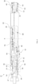
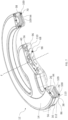
- Figs. 1 and 2 show an exemplary medical device support system 10 in which the proximity detection system may be implemented.
- the medical device support system 10 includes two light heads 12 in accordance with an embodiment of the invention.
- each light head 12 of the system 10 includes a housing base 14 and a housing cover 16 that together define an overall form and structure of the light head 12.
- Each light head 12 includes an annular shape outer portion 18, an inner round portion 20, and a radially protruding arm 22 that connects the annular shape outer portion 18 to the inner round portion 20.
- the housing base 14 and the housing cover 16 may be formed of metal, thermoplastic, or thermoset materials, or combinations of these materials. Other materials may be suitable.
- the light head 12 may be configured to be repositioned using a load balancing arm and yoke assembly.
- a bushing or other coupling member 24 is provided on each light head 12 for rotatably connecting the respective light head 12 to a distal arm 26 of a yoke assembly 28.
- the yoke assembly 28 is arranged on a distal end of a load balancing arm 30 and is configured to support the respective light head 12 for multi-axis movement relative to the load balancing arm 30.
- the medical device support system 10 may include two load balancing arms 30, one for each light head 12, and each load balancing arm 30 may be pivotably mounted to a distal end of an extension arm 32.
- the extension arm 32 is mounted to a central shaft or support column 34 that is suspended from the ceiling, or mounted to a wall or stand.
- the extension arm 32 is configured for rotational movement about the shaft 34.
- the housing cover 16 includes a housing lens 36 and each light head 12 further includes an annular shape lens 38, a plurality of light emitting elements 40, and a motion transfer member 42.
- the housing lens 36 and the annular shape lens 38 are arranged in a light emitting path LP of the plurality of light emitting elements 40.
- the motion transfer member 42 may include a lever, gear arrangement, or articulating assembly and is configured to movably interact with a boss 44 of the annular shape lens 38 to rotate the annular shape lens 38 about a rotational axis R within an interior cavity 46 of the housing cover 16.
- a driving source 48 such as a handle of the light head 12 may be movably coupled with the motion transfer member 42, such that motion from the driving source 48 translates into rotation of the annular shape lens 38 about the rotational axis R.
- the annular shape lens 38 may be rotated to adjust the distribution of light from the light head 12.
- movement of the driving source 48 is transferred to the annular shape lens 38 via a lever 50 and a motion transfer assembly 52. The motion occurs within a low overall height structure which is advantageous for maneuverability of the light head 12 and enabling a structure that has improved laminar flow conditions.
- an inside surface 54 of the housing base 14 supports the plurality of light emitting elements 40, which may be for example light emitting diodes (LEDs) or any other suitable light source.
- a plurality of collimators 56 are also mounted to the inside surface 54 of the housing base 14 and in the light emitting paths LP of the respective plurality of light emitting elements 40.
- the collimators 56 collect and direct, and/or collimate, the light into narrow beams.
- the collimators 56 may comprise total internal reflection (TIR) lenses.
- TIR total internal reflection
- the light emitting elements 40, the collimators 56, the annular shape lens 38, and the housing lens 36 may have an axial arrangement where axial refers to the direction of emission of light from the light heads 12, or downward in Fig. 2 .
- each light head 12 is communicatively coupled with a control system 66 which includes control elements integrated into the light head housing, handle, or support structure.
- the control system 66 may include a main processor 66a including any suitable microprocessor, control processing unit (CPU), control circuitry, or the like.
- a controller 66b may be communicatively coupled between the processor 66a and components in the light head 12 for adjusting the components based on instructions received from the processor 66a.
- the controller 66b may be configured to adjust an intensity of the light emitting elements 40.
- FIG. 4 each light head 12 is communicatively coupled with a control system 66 which includes control elements integrated into the light head housing, handle, or support structure.
- the control system 66 may include a main processor 66a including any suitable microprocessor, control processing unit (CPU), control circuitry, or the like.
- a controller 66b may be communicatively coupled between the processor 66a and components in the light head 12 for adjusting the components based on instructions received from the
- a memory 66c may also be provided as part of the control system 66.
- the memory 66c may contain stored data pertaining to operation of the light head 12 that is used by the processor 66a in providing instructions to the controller 66b.
- the memory 66c may be configured to store data pertaining to a default light intensity for the light emitting elements 40 or a look-up table having data pertaining to position or light intensity adjustments that correspond to particular blockages. Further details of an exemplary surgical light and system for identification of illumination abnormalities and automatic compensation suitable for the present application are described in U.S. Provisional Application No. 16/393,168 filed April 24, 2019 , and titled "System and Method for Identification of Illumination Abnormalities and Automatic Compensation Therefor," which is attached herewith, and which is incorporated by reference for all purposes as if fully set forth herein.
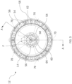
- the control system 66 further includes a plurality of proximity or distance sensors or detectors 68, 70, which may also be referred to as sensors, proximity sensors, optical transceivers, or optical emitters, that are integrated into the light head 12 (shown in Figs. 2 and 3 ).
- the plurality of distance sensors 68, 70 are in communication with the processor 66a (shown in Fig. 4 ) and are configured to provide readings representing the distance between the distance sensors 68, 70 and incident light on an object such as a patient, surgical equipment, or a physician's head or hand, to the processor 66a.
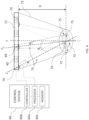
- the plurality of distance sensors 68, 70 are arranged in the housing cover 16 of the light head 12 and are configured to detect the distance to the object, where the distance sensor 68, 70 has within a field of view (FOV) of the distance sensor 68, 70 a target region of interest 72 that is a distance D from the distance sensors 68, 70.
- the control system 66 is configured to control the lighting of the light head 12 based on at least in part the detected data received from the distance sensors 68, 70.
- the processor 66a may be configured to determine an average of all of the measurements received from the distance sensors 68, 70.
- the target region of interest 72 may include a specific target, such as a patient on a surgical table.
- a target may be defined as an area which the user intends to illuminate by aiming the light 73 produced by the surgical light.
- the target region of interest 72 may be defined as the area that is illuminated by the light head 12 which is typically at a distance of one meter from the light head 12. "Target" "region of interest,” “target region”, and “target region of interest,” etc. may be used with reference to the same area.
- the target region of interest 72 is formed by the light emitting elements 40 that emit light and the lenses 36, 38, 56 that aim, redirect, spread, converge, and or focus the light.
- a center line of focus F of the light head 12 is defined by a central axis of the target region of interest 72 that is formed by the illumination, i.e. an axis extending through the point at which the light beam converges or focuses.
- the center line of focus F may be the same as or proximate the rotational axis R of the annular shape lens 38 (shown in Fig. 2 ) and the center line of focus F may be directly centered in the light head 12 or slightly offset depending on the geometry of the light head 12 and the positioning and aiming of the light emitting elements 40 and the positioning and adjusting capabilities of the lenses 36, 38, 56.
- the distance sensors 68, 70 may include any suitable sensor type.
- the distance sensors 68, 70 may use visible light, infrared light, ultrasonic waves or any other known output for measuring the distance D from the light head 12 to the target.
- the distance D may be approximately one meter.
- Each distance sensor 68, 70 has a field of view (FOV) 74 that extends outwardly from the corresponding distance sensor 68, 70 and defines a detection region of interest 75 for the corresponding distance sensor 68, 70.
- FOV field of view
- the FOV 74 may be defined as the area that is seen when looking outwardly from the point along the light head 12 where the distance sensor 68, 70 is located, whereas the detection region of interest 75 for the distance sensor 68, 70 may be defined as the area from which the distance sensor makes measurements.
- Each distance sensor 68, 70 may be oriented such that the corresponding detection region of interest 75 is aimed at the focal point of the light emitted from the light head 12.
- each distance sensor 68, 70 is increasing.
- Each distance sensor 68, 70 is oriented at an oblique angle relative to the center line of focus F such that each FOV 74 is slanted or tilted relative to the center line of focus F.
- the FOV 74 of each distance sensor 68, 70 may define a cone of sensitivity or a frustoconical shape that is radially increasing starting from where the corresponding distance sensor 68, 70 is mounted to the light head 12.
- the frustoconical shape may define a central axis C 1 , C 2 and have an opening angle A that is between 5 and 40 degrees.
- the opening angle A may be approximately 20 degrees.
- Each FOV 74 may have the same opening angle or a different opening angle.
- the distance sensors 68, 70 have slanted or tilted orientation such that the FOVs 74 of at least two of the distance sensors 68, 70 overlap at the detection region of interest 75 to define a common FOV area and thus a common detection region of interest 76.
- the common detection region of interest 76 of the distance sensors 68, 70 at least partially overlaps with the target region of interest 72.
- the distance sensors 68, 70 may include at least one inner distance sensor 68 that is arranged proximate the center line of focus F and a plurality of outer distance sensors 70 that are radially spaced relative to the inner distance sensor 68.
- the plurality of distance sensors 68, 70 may be obliquely angled relative to the center line of focus F.
- an angle B 1 between the central axis C 1 of the FOV 74 of the outer distance sensor 70 and the center line of focus F may be between 10 and 20 degrees. In the illustrative embodiment, the angle B 1 is approximately 16.5 degrees. The other outer distance sensors 70 may have the same angle B 1 or different angles.
- the angle B 2 between the central axis C 2 of the FOV 74 of the inner distance sensor 68 and the center line of focus F may be less than the angle B 1 , such as between 0.5 degrees and 10 degrees. In the illustrative embodiment, the angle B 2 is approximately three degrees. Accordingly, the FOV 74 of the inner distance sensor 68 extends more nearly parallel relative to the center line of focus F as compared with the FOV 74 of the outer distance sensor 70.
- the plurality of distance sensors 68, 70 may include only a single inner distance sensor 68 and a plurality of outer distance sensors 70 that are spaced radially outwardly relative to the single distance sensor 68.
- the distance sensors 68, 70 may be integrated into the housing cover 16 (shown in Fig. 1 ).
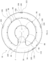
- the plurality of outer distance sensors 70 are arranged along a periphery, in the illustrative embodiment a circumference, of the housing cover 16 in a spaced relationship relative to each other such that all of the distance sensors 68, 70 are spaced and separated relative to each other.
- the single inner distance sensor 68 may be arranged radially offset relative to the center line of focus F.
- distance sensors 68, 70 may be used. Between five and ten distance sensors 68, 70 may be used. The distance sensors 68, 70 may be separate and spaced about the housing 14, 16. For example, as shown in Fig. 3 , six distance sensors 68, 70 may be used including five outer distance sensors 70 that are evenly spaced by approximately 72 degrees. Using six distance sensors 68, 70 is advantageous in that blockage of between one and three detectors, for example by a surgeon's body or surgical tools, does not adversely impact the readings of the remaining detectors. For example, the processor 66a may use a voting algorithm that ignores the blocked detection measurement and the resulting averaged distance is unaffected. Other arrangements of the distance sensors 68, 70 may be suitable. For example, the distance sensors 70 may have a non-uniform or uneven distribution about the housing cover 16 of the light head 12.
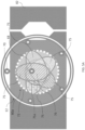
- Figs. 5A-5C show a detection region pattern 80a, 80b, 80c provided by the arrangement of the distance sensors 68, 70 of Fig. 3 relative to a surgical table 82.
- Fig. 5A shows the detection region pattern 80a when the distance sensors 68, 70 are oriented such that the distance D between the distance sensors 68, 70 and the target is approximately one meter.
- the light head 12 is configured to provide the converging light that defines the target region of interest 72 for illumination and each distance sensor 68, 70 is configured to have a corresponding detection region of interest 75, as defined by the FOV 74 (shown in Fig. 4 ), that overlaps with the target region of interest 72 of illumination.
- More than two detection regions of interest 75 may overlap with each other and the detection region of interest 75 (shown as 75a in Figs. 5A-5C ) of the single inner distance sensor 68 arranged proximate the center line of focus F may overlap with all of the detection regions of interest 75 of the outer distance sensors 70.
- Fig. 5B shows the detection region pattern 80b when the distance sensors 68, 70 are arranged at a distance D that is less than one meter relative to the target.
- the region of interest 75a of the single inner distance sensor 68 still overlaps with each of the detection regions of interest 75 of the outer distance sensors 70 such that the target region of interest 72 is overlapped by at least two detection regions of interest 75, 75a.
- Fig. 5C shows the detection region pattern 80c when the distance sensors 68, 70 are arranged at a distance D that is greater than one meter relative to the target.
- Fig. 5C shows the regions of interest 75, 75a overlapping with the target region of interest 72.
- the target region of interest 72 and the detection regions of interest 75 may have different shapes and the shapes may be dependent on the distance D between the light head 12 and the target.
- the target region of interest 72 for illumination may be circular and the detection regions of interest 75 for the distance sensors 68, 70, as defined by the FOVs, may be elliptical as illustrated or oval or circular in shape.
- the detection region of interest 75 (shown as 75a in Figs. 5A-5C ) for the inner distance sensor 68 may be circular as illustrated or elliptical or oval in shape.
- the distance sensors 68, 70 may be oriented such that the detection regions of interest 75 converge at approximately one meter from the light head (for example perpendicularly downward in Fig.
- the distance sensors 68, 70 may be co-located with, or located proximate to the modules 58, 60 of the light emitting elements 40 at predetermined locations along the periphery of the housing cover 16 to further ensure maximum overlap and that readings are received from the target.
- the distance sensors 68, 70 may be located in the middle of the modules 58, 60.
- the distance sensor 70 may be arranged between two sets of three light emitting elements 40. Arranging the distance sensors 68, 70 proximate the modules 58, 60 enables control of the modules 58, 60 in a one to one ratio with the detected blockage.
- each distance sensor may be integrated into the housing cover 16 of the light head via support features that are integrally formed in the housing cover 16.
- the housing cover 16 may be formed as a single monolithic component and include an annular shape outer cover 86 and an inner round cover 88 that are connected by an arm cover 90 extending radially therebetween.
- the radially extending arm cover 90 may also arrange the annular shape outer cover 86 and the inner round cover 88 in concentric relation to one another, and/or in concentric relation to the rotational axis R of the annular shape lens 38 (shown in Fig. 2 ).
- the housing cover 16 defines the interior cavity 46 which has three interconnected portions corresponding to the annular shape outer cover 86, the inner round cover 88, and the arm cover 90 extending radially therebetween.
- the housing cover 16 also includes the housing lens 36 which includes an annular shape outer lens 94 and an inner round lens 96.
- the annular shape outer lens 94 forms a bottom surface of the annular shape outer cover 86 and the inner round lens 96 forms a bottom surface of the inner round cover 88.
- the bottom wall of the annular shape outer cover 86 and/or the inner round cover 88 may be formed by a transparent non-lens material, i.e. a non-light bending material, and the annular shape outer lens 94 and/or the inner round lens 96 may be positioned, for example, above the transparent non-lens bottom walls and secured to surrounding structure of the housing cover 16.
- the annular shape outer lens 94 and the inner round lens 96 are arranged in the light emitting paths LP of the plurality of light emitting elements 40 (shown in Fig. 2 ).
- the annular shape lens 38 (shown in Fig. 2 ) is positioned between the annular shape outer lens 94 and the light emitting elements 40 in the light emitting path LP.
- the collimators 56 (shown in Fig. 2 ) are also arranged in the light emitting paths LP of the plurality of light emitting elements 40 in the annular shape outer portion 18 (shown in Fig.
- the annular shape lens 38 and the housing lens 36, and the collimators 56 if provided, can take on any form for spreading and/or bending the light emitted by the light emitting elements 40.
- the distance sensors 68, 70 operate in conjunction with the light emitting elements 40 and lenses 36, 38, 56 and are integrated into the housing cover 16 via tilted seats 98, 100 that are slanted or tilted and formed in the housing cover 16.
- the tilted seats 98, 100 are configured to support the distance sensors 68, 70 (shown in Figs. 3-5 ) and position the distance sensors 68, 70 relative to the light emitting elements 40 and lenses 36, 38, 56.
- the distance sensors 68, 70 may be obliquely angled toward the center line of focus F when seated in the tilted seats 98, 100, whereby at least two of the distance sensors 68, 70 have field of views that overlap to define the common detection region of interest 76.
- the tilted seats 98, 100 may be formed by a planar surface that defines a through-going aperture 102, such that a corresponding distance sensor 68, 70 is engageable against the planar surface and faces outwardly through the aperture 102 for performing detection.
- the apertures 102 of the tilted seats 98, 100 may have any suitable shape and the shape may correspond to a shape of the distance sensor.
- the apertures 102 may be circular, elliptical, or oval in shape.
- the housing cover 16 may further include threaded openings 106 that are formed in bosses 108 of the housing cover 16.
- the bosses 108 are circumferentially arranged and spaced and are configured to receive fasteners for connecting the housing base 14 and the housing cover 16 (shown in Fig. 1 ).
- a plurality of the bosses 108 are formed on the outer peripheral surface 105 in the annular shape outer cover 86 of the housing cover 16. Some of the bosses 108 may be formed adjacent the recessed portions 104 and the tilted seats 98, 100. Both the tilted seats 98, 100 and the bosses 108 may be molded or formed integrally with the housing cover 16 as a single monolithic component.
- the tilted seats 98, 100 may be positioned below the annular shape lens 38 which, in turn, is positioned below the collimators 56 and the light emitting elements 40 supported by the housing base 14.
- the annular shape lens 38 is positioned between the collimators 56 and the bottom wall 109 in which the tilted seat 100 is formed.
- the annular shape lens 38 may have a top surface that is formed as a stepped surface that bends individual portions of the light beams.
- the annular shape lens 38 may have a plurality of Fresnel wedges.
- the tilted outer seats 100 are formed at a radially outer portion of the bottom wall 109.
- the bottom wall 109 is continuous with a side wall 112 of the housing cover 16 that extends upright relative to the bottom wall 109 for engagement with the housing base 14.
- the tilted seat 100 is arranged proximate a curved wall 113 connecting the bottom wall 109 and the side wall 112.
- the bottom wall 109 and the side wall 112 may each be formed to have a non-uniform contour. For example, as shown in Fig.
- the radially inner and outer edges 116, 118 of the tilted seat 100 define the aperture 102 that receives the distance sensor 70 such that the distance sensor 70 includes an engaging surface that engages the perimeter of the aperture 102.
- the aperture 102 may be formed to have a dimension suitable to receive different types of distance sensors.
- the tilted seat 100 is formed to define a seating plane S which is defined as a plane within which the detecting face of the distance sensor 70 extends or the plane along which the distance sensor 70 contacts the tilted seat 100.
- the seating plane S is normal to the central axis C 1 of the distance sensor 70 (as also shown in Fig. 4 ).
- the seating plane S is tilted by an oblique angle E relative to a plane P in which the light head 12 extends, with the plane P being normal to the center line of focus F of the light head 12.
- the angle E may be between 10 and 20 degrees, and in exemplary embodiments, the angle E may be approximately 16.5 degrees. Many different angles are suitable.
- the distance sensor 70 is seated, meaning that the body of the distance sensor 70 rests against the tilted seat 100, the distance sensor 70 is angled radially inwardly to ensure that the detection region of interest of the distance sensor 70 overlaps with the target region of interest (shown in Fig. 4 ).
- Each tilted seat 100 corresponding to the outer distance sensors 70 may have the same shape and may be angled radially inwardly at a same angle relative to the plane P of the light head 12 and the center line of focus F. In other exemplary embodiments, the tilted seats 100 may be formed to have different angles such that each outer distance sensor 70 is oriented differently.
- the tilted seat 98 corresponding to the inner distance sensor 68 may be formed to have an angle G relative to the plane P that is smaller than the angle E between the seating plane S of the tilted seat 100 and the plane P.
- the angle G of the tilted seat 98 may be less than 10 degrees such that the inner distance sensor 68 is arranged more nearly parallel with the plane P of the light head 12 as compared with the outer distance sensor 70.
- the bottom wall 110 of the inner round cover 88 is formed to define a bottom surface of the tilted seat 98 that receives the inner distance sensor 68.
- the bottom wall 110 may have a planar bottom surface 120.
- the angle of the tilted seat 98 may be formed by a tilted surface formed in the recessed portion 104 (shown in Fig. 6 ) against which the distance sensor 68 is seated.
- the tilted seats 98, 100 may be formed to have many different angles and position the distance sensors 68, 70 in different orientations. Forming the tilted seats 98, 100 with the housing cover 16 as a monolithic component is advantageous in that the positioning of the distance sensors 68, 70 is ensured in forming the housing cover 16 and the light head 12 is formed to arrange and aim the distance sensors 68, 70 without impeding the emitted light.
- the distance sensors 68, 70 may be mounted and angled by brackets or other separate attachment mechanisms, including clamps, pins, screws, bolts, adhesives, or any other suitable device.
- the housing cover 16 may be formed without the tilted seats 98, 100.
- each distance sensor 68, 70 may be arranged in a distance sensor assembly 200 such that any distance sensor 68, 70 previously shown may be a distance sensor assembly 200.
- the light head may include six distance sensor assemblies 200 in place of the distance sensors 68, 70 shown in Fig. 3 .
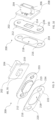
- Figs. 9 and 10 show exploded views of the distance sensor assembly 200
- Figs. 11 and 12 show the distance sensor assembly 200 as assembled
- Fig. 13 shows a front view of the distance sensor assembly 200
- Fig. 14 shows a cross-sectional view of the distance sensor assembly 200 as cut along line B-B in Fig. 13 .
- the distance sensor assembly 200 is configured to be implemented in the light head 12 (shown in Figs.
- the distance sensor assembly 200 includes a printed circuit board assembly (PCBA) 202 that has an electrical interface 204, such as a plug, the distance sensor 68, 70, and associated electronics 206.
- the electrical interface 204 is disposed on a first surface 208 of the PCBA 202 and extends outwardly from the first surface 208.
- the distance sensor 68, 70 is disposed on a second surface 210 of the PCBA 202 that opposes the first surface 208.
- the electrical interface 204 is configured to provide power and communication to the distance sensor 68, 70 from a power source and communication line of the medical device support system 10 (shown in Fig. 1 ).
- the distance sensor 68, 70 may be an infrared distance sensor, but other sensors may be suitable.
- the distance sensor assembly 200 may further include an optical component 212 that is configured for aiming, orienting, and protecting the distance sensor 68, 70.
- the optical component 212 may be configured to be matingly engageable against a corresponding one of the tilted seats 98, 100 and coupled to the printed circuit board assembly 202.
- the optical component 212 may be arranged to cover the distance sensor 68, 70 adjacent the second surface 210 of the PCBA 202 and is also configured to be sealed relative to the light head housing, such as the housing cover.
- a complementary recess 214 may be formed in the optical component 212 to receive and support the distance sensor 68, 70.
- the distance sensor 68, 70 of the distance sensor assembly 200 may be configured to transmit and receive distance sensing signals through the optical component 212.
- the optical component 212 may be configured to enable passage of infrared light and block visible light. In other embodiments, the optical component 212 may enable passage and/or blockage of other electromagnetic or ultrasonic waves.
- the optical component 212 is also advantageous in providing ingress protection for the housing cover 16 by preventing contaminants from entering into the housing cover 16.
- the optical component 212 may be sealed relative to the light head 12, such as relative to the housing cover 16 (shown in Fig. 7 ), by any suitable adhesive layer 216.
- the adhesive layer 216 may be disposed between the optical component 212 and the housing 14, 16.
- the adhesive layer 216 may be disposed between the optical component 212 and a corresponding one of the tilted seats 98, 100.
- the adhesive layer 216 provides an interface between the distance sensor assembly 200 and the housing cover 16.
- the adhesive layer 216 may be formed as a thin tape material and may have a thickness that is less than a thickness of the optical component 212.
- An acrylic adhesive material may be suitable.
- Double-sided foam tapes formed of acrylic adhesive material may be suitable. Still other adhesives may be suitable.
- a protruding portion 219 of the optical component 212 may have a shape that is complimentary to the aperture 102 formed by the corresponding tilted seat 98, 100 (shown in Fig. 6 ) such that the optical component 212 is configured for matingly engaging with a perimeter of the aperture 102.
- the mating engagement between the optical component 212 and the perimeter of the aperture 102 may itself seal the aperture 102 and provide ingress protection, in addition to or as an alternative to the sealing provided by the adhesive layer 216.
- the protruding portion 219 of the optical component 212 may be oval in shape as shown, or other shapes.
- the adhesive layer 216 may have a shape that is complimentary to the shape of the optical component 212.
- Each of the adhesive layer 216 and the optical component 212 may be elongated such that the elongate outer ends of the components engage the housing cover 16 and the portion in between, or inner portion, supports the distance sensor 68, 70.
- the optical component 212 and the adhesive layer 216 may both be oval in shape and have a common outer perimeter.
- Opposite end portions 220, 222 of the adhesive layer 216 are engageable against the housing cover 16 such that the adhesive layer 216 provides the sealing engagement between the housing cover 16 and the distance sensor assembly 200 when the distance sensor assembly 200 is seated in a corresponding tilted seat.
- the adhesive layer 216 may engage against the surface defining the recessed portion 104 of the housing cover 16 (shown in Fig. 6 ).
- another adhesive material 224 may be provided between the PCBA 202 and the optical component 212, such as between a PCBA-facing surface 226 of the optical component 212 and the second surface 210 of the PCBA 202.
- the adhesive material 224 may be a cyanoacrylate material or other acrylate material. Other adhesive materials may be suitable.
- an air gap 227 may be defined between the distance sensor 68, 70 and the optical component 212.
- the air gap 227 enables calibration of the distance sensor 68, 70 according to manufacturer specifications.
- Providing the air gap 227 is also advantageous in providing a clearance for mounting the optical component 212 with the PCBA 202 and over the distance sensor 68, 70 to enclose the distance sensor 68, 70.
- the distance sensor 68, 70 may be positioned behind the housing cover without the optical component.
- the optical component may be integrally formed with the housing cover as a single monolithic component.
- the optical component 212 may be integrally formed with the housing base or the housing cover. Other arrangements of the optical component may also be suitable.
- the optical component may be co-located or located proximate the light-emitting element.
- the distance sensor assembly 200 may be mounted to the housing cover 16 using features formed integrally with the housing cover 16, separate attachment mechanisms, or a combination thereof.
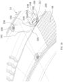
- the bottom wall 109 of the annular shape outer cover 86 may be formed to have a plurality of locating posts 228, 230 that protrude from the housing cover 16 to support the distance sensor assembly 200.
- the locating posts 228, 230 may be formed on the tilted seats 98, 100 and engageable with a corresponding one of the distance sensor assemblies 200.
- the locating posts 228, 230 may be molded or formed integrally with the housing cover 16 as a single monolithic structure that extends from the tilted seat 98, 100 of the housing cover 16.
- Each locating post 228, 230 may extend upwardly from the bottom wall 109 into the interior cavity 46 of the housing cover 16 such that the locating posts 228, 230 are accommodated inside the housing cover 16.
- the interior cavity 46 may be formed by the side wall 112 and the bottom wall 109 of the housing cover 16.
- the direction in which the locating posts 228, 230 extend may be normal or obliquely angled relative to the tilted seat 98, 100.
- the locating post 228, 230 may have any suitable shape such as a tapered and/or cylindrical shape.
- the locating posts 228, 230 may be formed radially outwardly relative to the annular shape lens 38 such that the locating posts 228, 230 do not interfere with a rotational path of the annular shape lens 38.
- Each distance sensor assembly 200 is formed to have a corresponding locating feature for mounting the distance sensor assembly 200 relative to the locating post 228, 230 such that the locating post 228, 230 limits axial movement of the distance sensor assembly 200 relative to the locating post 228, 230.
- the engaging portion may be formed as through-holes through which the locating posts 228, 230 extend. Forming the locating posts 228, 230 to be tapered enables the optical component 212 to slide down the locating post 228, 230 thereby aligning the optical component 212, and thus the distance sensor assembly 200, in the x-y plane.
- the locating posts 228, 230 may protrude from a corresponding one of the tilted seats 98, 100 and have a tapered shape that tapers in a protrusion direction away from the corresponding one of the tilted seats 98, 100.
- the locating posts 228, 230 may be tapered radially inwardly in the protruding direction of the locating posts 228, 230 relative to the tilted seat 100.
- the shape of the locating posts 228, 230 may enable the optical component 212 to have a rocking movement for adjusting the optical component 212 until the optical component 212 is engaged against the tilted seat 98, 100.
- a thicker base portion 232 of the locating post 228 may limit lateral movement of the optical component 212.
- the tilted seat 100 is formed as an alignment surface that captures the distance sensor assembly 200 in the z-direction and orients the distance sensor assembly 200 rotationally.
- each end portion of the optical component 212 is formed with through-holes 233 that are configured to receive a corresponding locating post 228, 230.
- the locating posts 228, 230 may be formed on the tilted seats 98, 100 to be engageable with the optical component 212, for example, by the locating posts 228, 230 extending through the opposite end through-holes 233.
- the number of apertures formed in the optical component 212 may correspond to the number of locating posts 228, 230.
- Two locating posts 228, 230 may be suitable. In other embodiments, one or more than two locating posts 228, 230 may be provided.
- the adhesive layer 216 is formed with through-holes 234 that correspond to the through-holes 233 of the optical component 212 and are configured to receive the corresponding locating post 228, 230.
- Each through-hole 233, 234 may be circular in shape or have a shape that is suitable for receiving the locating post 228, 230.
- the through-holes 234 of the adhesive layer 216 may be formed to have a larger diameter relative to the diameter of the through-holes 233 of the optical component 212 to provide clearance during assembly of the distance sensor assembly 200.
- the adhesive layer 216 and the optical component 212 face or mate with the engaging surface of the tilted seat 100 defined by the bottom wall 109 of the annular shape outer cover 86. As shown in Fig. 16 , both the adhesive layer 216 and the optical component 212 are retained via the through-holes 233, 234 (shown in Figs. 9-14 ) receiving the locating posts 228, 230 therethrough.
- the PCBA 202 is positioned on the optical component 212 between the locating posts 228, 230 and the electrical interface or plug 204 extends upwardly past the locating posts 228, 230.
- the locating posts 228, 230 may be formed in the recessed portion 104 of the housing cover 16 that is adjacent the boss 108.
- the recessed portion 104 may be defined between sidewalls 236, 238 of the outer peripheral surface 105.
- the sidewalls 236, 238 extend normal to the surface that defines the tilted seat 100 (shown in Fig. 15 ).
- a back wall 240 extends axially between the sidewalls 236, 238 and is formed to have a curvature such that the locating posts 228, 230 and the distance sensor assembly 200 are fully accommodated within the recessed portion 104 and do not protrude past a height of the sidewalls 236, 238.
- the height of the sidewalls 236, 238 may be formed to be lower relative to a bottom 242 of the boss 108 that includes the threaded openings 106 for securing the housing cover 16 and the housing base.
- the locating posts 228, 230 may undergo an ultrasonic heat staking process, whereby the locating posts 228, 230 are deformed to form an interference fit with the distance sensor assembly 200.
- the heat staking of the locating posts 228, 230 may be used as an added or alternative means to the adhesive layer 216 for sealing the optical component 212 to the housing cover 16.
- Other securing methods and devices may be used to mount the distance sensor assembly 200 to the housing cover 16.
- the distance sensor assembly 200 may be integrated in the housing cover 16 via ultrasonic welding, a threaded connection, or a press-fit connection.
- Any suitable manufacturing method may be used to form a light head having any of the features aforementioned.
- processes such as injection molding, blow molding, thermoforming, transfer molding, reaction injection molding, compression molding, and extrusion, or any combination thereof may be suitable.
- a first step 302 of the method 300 may include arranging a plurality of light emitting elements 40 in a housing 12 (shown in Fig. 2 ) to direct light at a target region of interest 72 (shown in Fig. 4 ).
- a step 304 of the method 300 may include arranging at least two distance sensors 68, 70 to have field of views 74 that overlap to define a common detection region of interest 75 (shown in Fig. 4 ). The common detection region of interest 75 at least partially overlaps with the target region of interest 72.
- a step 304 of the method 300 includes arranging the at least two distance sensors 68, 70 to be obliquely angled toward a center line of focus F of the surgical light head 12 (shown in Fig. 4 ).
- Step 352 of the method 350 includes molding the housing 12 to have a plurality of tilted seats 98, 100 (shown in Figs. 6-8 ) as a single monolithic component.
- Step 352 may include molding locating posts 228, 230 (shown in Figs. 15 and 16 ) with the housing 12.
- Step 354 may include arranging the plurality of light emitting elements 40 in the housing 12 and step 356 of the method 350 includes spacing the plurality of distance sensors 68, 70 along a periphery of the housing 12.
- Step 358 of the method 350 includes orienting the plurality of distance sensors 68, 70 to be obliquely angled toward the center line of focus F of the surgical light head 12.
- Step 358 may include arranging the plurality of distance sensors 68, 70 against the plurality of tilted seats 98, 100 to position the plurality of distance sensors 68, 70.
- Step 360 of the method 350 includes forming a distance sensor assembly 200 (shown in Figs. 9-14 ).
- Step 360 may include communicatively coupling the housing 12 and one of the plurality of distance sensors 68, 70 with a PCBA 202 and mounting the PCBA 202 to an optical component 212.
- Mounting the PCBA 202 to the optical component 212 may include covering the distance sensor 68, 70 with the optical component 212 such that the distance sensor 68, 70 is configured to transmit and receive distance sensing signals through the optical component 212.
- An air gap 227 may be defined between the distance sensor 68, 70 and the optical component 212.
- the method 350 may further include a step 362 of sealing the optical component 212 relative to the housing 12.
- Step 362 may include engaging the optical component 212 with the locating posts 228, 230 to position the distance sensor assembly 200.
- a heat staking process may be used to secure the optical component 212 and the locating posts 228, 230.
- the surgical light head having any combination of the features described herein is advantageous in that the surgical light head has improved proximity detection.
- Forming the distance sensors to be spaced about the light head and obliquely angled toward the center line of focus ensures accuracy in the detected distance measurements, such that blockage of one sensor will not significantly impede the measurements, such as the voted output measurements, from the other sensors.
- Integrating the sensors into the light head via the tilted seats and/or the optical component ensures proper aiming of the distance sensors and provides ingress protection for the light head without sacrificing accuracy of the distance sensors.
Landscapes
- Health & Medical Sciences (AREA)
- Engineering & Computer Science (AREA)
- Life Sciences & Earth Sciences (AREA)
- Surgery (AREA)
- Animal Behavior & Ethology (AREA)
- Molecular Biology (AREA)
- Veterinary Medicine (AREA)
- Public Health (AREA)
- General Health & Medical Sciences (AREA)
- Nuclear Medicine, Radiotherapy & Molecular Imaging (AREA)
- Oral & Maxillofacial Surgery (AREA)
- Pathology (AREA)
- Medical Informatics (AREA)
- Heart & Thoracic Surgery (AREA)
- Biomedical Technology (AREA)
- Physics & Mathematics (AREA)
- General Engineering & Computer Science (AREA)
- Computer Networks & Wireless Communication (AREA)
- Electromagnetism (AREA)
- Radar, Positioning & Navigation (AREA)
- General Physics & Mathematics (AREA)
- Remote Sensing (AREA)
- Length Measuring Devices By Optical Means (AREA)
- Photometry And Measurement Of Optical Pulse Characteristics (AREA)
Description
- This application relates generally to a surgical light, and more particularly to a system for aiming and controlling a light output and proximity detection of surgical lights.
- Surgical lights are used in operating rooms to provide increased light to a specific area of the room. For example, the surgical light may be positioned in an operating room and configured to provide increased light to a specific area of a surgical patient. The light may include a light housing containing a light source and a distance sensor that measures a distance from the light housing to the object to be illuminated, such that attributes of the light emitted from the light housing may be altered based on the distance detected by the distance sensor. However, conventional sensor systems may be susceptible to blockage that results in inaccurate measurements. For example, a head of a surgeon or other medical professional may block the sensor and consequently cause inaccurate distance measurements.
- Below some background documents will be identified and briefly discussed.
-
US2015/208478 relates to a method for improving the illumination of an illuminated area, especially an operating area, of an illuminating device with at least two light modules. The method includes the emission of an illuminant characteristic of the light module with a preset amplitude from each light module. The reflected amplitudes of all characteristic light types are detected. The detected amplitudes for each light module are compared. The light intensity of at least one light module is varied on the basis of the comparison of the detected amplitudes for each light module. -
US9638406 -
CN102252216 relates to a shadow-less lighting lamp with a brightness compensation mechanism. -
US2018/209623 relates to a handle device for a surgical light. The handle device may include a grip element which is prepared for being arranged on a lamp holding body of the surgical light and which forms a grip surface at an outer area. A sensor module is detachably connected to the grip element, with the sensor module including at least one distance sensor which is designed for detecting a position of an object. The present application further includes a surgical light including such a handle device. -
US2017/0030573 relates to surgical lights and systems and method for maximizing the output of surgical lights by measuring with a distance sensor the distance from a light housing to an object to be illuminated and altering attributes of the emitted light depending on the measured distance. - The invention is defined by the features of the
independent claims 1 and 16. - Embodiments of the invention may include one or more of the following additional features separately or in combination.
- The plurality of distance sensors may be mounted along a periphery of the housing in a spaced relationship relative to each other.
- The plurality of distance sensors may be evenly spaced.
- The plurality of distance sensors may be obliquely angled relative to a center line of focus of the surgical light head.
- The plurality of distance sensors may be obliquely angled relative to the center line of focus by an angle that is between 0.5 and 20 degrees.
- The plurality of distance sensors may include a single inner distance sensor arranged proximate the center line of focus and a plurality of outer distance sensors that are radially spaced relative to the inner distance sensor.
- The surgical light head may further include an annular shape first lens that has a rotation axis, wherein the housing includes a housing cover including a cavity within which the annular shape first lens is rotatable about the rotation axis, wherein the housing cover includes a second lens, and wherein the outer distance sensors are arranged radially outwardly relative to the annular shape first lens and the second lens.
- The field of views may be defined by cones having an opening angle that is between 5 and 40 degrees.
- The plurality of distance sensors may include between five and ten distance sensors that are separate and spaced about the housing.
- The housing may define a plurality of seats configured for supporting the plurality of distance sensors. The seats may be obliquely angled toward a center line of focus of the surgical light head.
- The plurality of seats may be molded with the housing as a single monolithic component.
- The plurality of seats may include a single inner seat formed proximate the center line of focus and a plurality of outer seats that are formed on a periphery of the housing and radially spaced from the inner seat.
- The surgical light head may include a plurality of distance sensor assemblies that each include a corresponding one of the plurality of distance sensors and a printed circuit board assembly including an electrical interface communicatively coupled between the housing and the corresponding one of the plurality of distance sensors.
- Each of the plurality of distance sensor assemblies may include an optical component that covers the corresponding one of the plurality of distance sensors. The optical component may be sealed to the housing and coupled to the printed circuit board assembly. The corresponding one of the plurality of distance sensors may be configured to transmit and receive distance sensing signals through the optical component.
- The surgical light head may include an adhesive layer disposed between the optical component and the housing.
- The printed circuit board assembly and the optical component may be adhered by an acrylate adhesive material.
- The distance sensor and the optical component may define an air gap therebetween.
- The surgical light head may include a plurality of locating posts formed on the housing that are engageable with the optical component.
- The plurality of locating posts may be integrally formed with the housing as a single monolithic component.
- The locating posts may have a tapered shape.
- The plurality of distance sensors may be infrared distance sensors.
- According to another aspect of the disclosure, a surgical light head includes a housing defining a center line of focus of the surgical light head, a plurality of distance sensors, and a plurality of tilted seats formed on the housing and configured for supporting the plurality of distance sensors. The plurality of tilted seats are obliquely angled toward the center line of focus.
- The plurality of tilted seats may be molded with the housing as a single monolithic component.
- The plurality of tilted seats may include a single inner seat formed proximate the center line of focus and a plurality of outer seats that are formed on a periphery of the housing and radially spaced from the inner seat.
- The surgical light head may include an annular shape first lens that has a rotation axis. The housing may include a housing cover including a cavity within which the annular shape first lens is rotatable about the rotation axis, wherein the housing cover includes a second lens, and the outer seats may be arranged radially outwardly relative to the annular shape first lens and the second lens.
- The plurality of tilted seats may be obliquely angled relative to the center line of focus by an angle that is between 0.5 and 20 degrees.
- The surgical light head may include a plurality of distance sensor assemblies that each include a corresponding one of the plurality of distance sensors and a printed circuit board assembly including an electrical interface communicatively coupled between the housing and the corresponding one of the plurality of distance sensors.
- Each of the plurality of distance sensor assemblies may include an optical component that covers the corresponding one of the plurality of distance sensors. The optical component may be matingly engageable against a corresponding one of the tilted seats and coupled to the printed circuit board assembly and the corresponding one of the plurality of distance sensors may be configured to transmit and receive distance sensing signals through the optical component.
- The surgical light head may include an adhesive layer disposed between the optical component and the corresponding one of the tilted seats.
- The printed circuit board assembly and the optical component may be adhered by an acrylate adhesive material.
- The distance sensor and the optical component may define an air gap therebetween.
- The surgical light head may include a plurality of locating posts that are formed on the plurality of tilted seats and engageable with a corresponding one of the plurality of distance sensor assemblies.
- The plurality of locating posts may be integrally formed with the housing as a single monolithic component.
- The locating posts may protrude from a corresponding one of the plurality of tilted seats and have a tapered shape that tapers in a protrusion direction away from the corresponding one of the plurality of tilted seats.
- The plurality of distance sensors may be infrared distance sensors.
- The surgical light head may include a plurality of light emitting elements arranged in the housing and configured to direct light at a target region of interest that defines the center line of focus. The plurality of distance sensors may be obliquely angled toward the center line of focus when seated in the tilted seats, whereby at least two of the distance sensors have field of views that overlap to define a common detection region of interest. The common detection region of interest may at least partially overlap with the target region of interest.
- The plurality of distance sensors may be mounted along a periphery of the housing in a spaced relationship relative to each other.
- The plurality of distance sensors may be evenly spaced.
- The plurality of distance sensors may include a single inner distance sensor and a plurality of outer distance sensors that are radially spaced relative to the inner distance sensor.
- The field of views may be defined by cones having an opening angle that is between 5 and 40 degrees.
- The plurality of distance sensors may include between five and ten distance sensors that are separate and spaced about the housing.
- According to another aspect of the disclosure, a surgical light head includes a housing, and a plurality of distance sensor assemblies integrated into the housing. Each of the plurality of distance sensor assemblies includes a distance sensor, a printed circuit board assembly having an electrical interface communicatively coupled between the housing and the distance sensor, and an optical component that covers the distance sensor, with the optical component being sealed to the housing and coupled to the printed circuit board assembly. The distance sensor is configured to transmit and receive distance sensing signals through the optical component.
- The surgical light head may include an adhesive layer disposed between the optical component and the housing.
- The printed circuit board assembly and the optical component may be adhered by an acrylate adhesive material.
- The distance sensor and the optical component may define an air gap therebetween.
- The housing may define a plurality of tilted seats configured for supporting the plurality of distance sensor assemblies, with the tilted seats being obliquely angled toward a center line of focus of the surgical light head.
- The plurality of tilted seats may be molded with the housing as a single monolithic component.
- The plurality of tilted seats may include a single inner seat formed proximate the center line of focus and a plurality of outer seats that are formed on a periphery of the housing and radially spaced from the inner seat.
- The surgical light head may include a plurality of locating posts formed on the tilted seats that are engageable with the optical component.
- The locating posts may protrude from a corresponding one of the plurality of tilted seats and have a tapered shape that tapers in a protrusion direction away from the corresponding one of the plurality of tilted seats.
- The surgical light head may include a plurality of light emitting elements arranged in the housing and configured to direct light at a target region of interest, with at least two of the distance sensor assemblies having field of views that overlap to define a common detection region of interest. The common detection region of interest may at least partially overlaps with the target region of interest.
- The plurality of distance sensor assemblies may be mounted along a periphery of the housing in a spaced relationship relative to each other.
- The surgical light head may include an annular shape first lens that has a rotation axis, with the housing including a housing cover including a cavity within which the annular shape first lens is rotatable about the rotation axis. The housing cover may include a second lens, and the outer distance sensor assemblies may be arranged radially outwardly relative to the annular shape first lens and the second lens.
- The plurality of distance sensor assemblies may be evenly spaced.
- The plurality of distance sensor assemblies may be obliquely angled relative to a center line of focus of the surgical light head.
- The plurality of distance sensor assemblies may be obliquely angled relative to the center line of focus by an angle that is between 0.5 and 20 degrees.
- The plurality of distance sensor assemblies may include a single distance sensor assembly arranged proximate the center line of focus and a plurality of outer distance sensor assemblies that are radially spaced relative to the inner distance sensor assembly.
- The field of views may be defined by cones having an opening angle that is between 5 and 40 degrees.
- The plurality of distance sensor assemblies may include between five and ten distance sensor assemblies that are separate and spaced about the housing.
- According to another aspect of the disclosure, a method of proximity detecting for a surgical light head includes arranging a plurality of light emitting elements in a housing to direct light at a target region of interest, and arranging at least two distance sensors to have field of views that overlap to define a common detection region of interest. The common detection region of interest at least partially overlaps with the target region of interest.
- Arranging the at least two distance sensors may include angling the at least two distance sensors toward a center line of focus of the surgical light head.
- According to another aspect of the disclosure, a method of forming a surgical light head includes arranging a plurality of light emitting elements in a housing, spacing a plurality of distance sensors along a periphery of the housing, and orienting the plurality of distance sensors to be obliquely angled toward a center line of focus of the surgical light head.
- The method may include molding a housing having a plurality of tilted seats as a single monolithic component, with the plurality of tilted seats being obliquely angled toward the center line of focus, and arranging the plurality of distance sensors against the plurality of tilted seats to position the plurality of distance sensors.
- The method may include communicatively coupling the housing and one of the plurality of distance sensors with a printed circuit board assembly, mounting the printed circuit board assembly to an optical component, covering the distance sensor with the optical component, with the distance sensor being configured to transmit and receive distance sensing signals through the optical component, and sealing the optical component relative to the housing.
- The method may include molding locating posts with the housing as a single monolithic component and engaging the optical component with the locating posts.
- The method may include using a heat staking process to secure the optical component to the housing.
- The method may include defining an air gap between the distance sensor and the optical component.
- The following description and the annexed drawings set forth certain illustrative embodiments of the invention. These embodiments are indicative, however, of but a few of the various ways in which the principles of the invention may be employed. Other objects, advantages and novel features according to aspects of the invention will become apparent from the following detailed description when considered in conjunction with the drawings.
- The annexed drawings, which are not necessarily to scale, show various aspects of the invention.
-
Fig. 1 is a side elevation view of an overall configuration of a medical device support system in accordance with an embodiment of the invention, showing a top of a left positioned light head and a bottom a right positioned light head. -
Fig. 2 is a side cross section view of a light head in accordance with an embodiment of the invention, showing a housing base, a housing cover, and internal components of the light head. -
Fig. 3 is a bottom plan view of the housing base, a plurality of collimators, and a plurality of distance sensors. -
Fig. 4 shows a region of interest of the light head, fields of view of the distance sensors, and a control system for controlling the light head based on measurements of the distance sensors. -
Fig. 5A shows a detection pattern provided by the plurality of distance sensors. -
Fig. 5B shows a detection pattern provided by the plurality of distance sensors when the distance sensors are closer to the target than inFig. 5A . -
Fig. 5C shows a detection pattern provided by the plurality of distance sensors when the distance sensors are farther from the target than inFig. 5A . -
Fig. 6 is a top plan view of a housing cover including tilted seats for supporting the plurality of distance sensors. -
Fig. 7 is a perspective cross section view of the light head as cut along line A-A ofFig. 3 . -
Fig. 8 is a side cross section view of the light head showing the tilted seats and the distance sensors arranged in the tilted seats. -
Fig. 9 is an exploded perspective view of a distance sensor assembly that includes a distance sensor and an optical component. -
Fig. 10 is another exploded perspective view of the distance sensor assembly. -
Fig. 11 is a front perspective view of the assembled distance sensor assembly. -
Fig. 12 is a rear perspective view of the assembled distance sensor assembly. -
Fig. 13 is a front plan view of the assembled distance sensor assembly. -
Fig. 14 is a side cross section view of the assembled distance sensor assembly as cut along line B-B ofFig. 13 . -
Fig. 15 is a side cross section view of a portion of the light head, showing a locating post, the tilted seat, and the distance sensor assembly. -
Fig. 16 is a top perspective cross section view of a portion of the light head, showing locating posts and the distance sensor assembly. -
Fig. 17 is a flowchart showing a method of proximity detection for a surgical light. -
Fig. 18 is a flowchart showing a method of forming a surgical light. - While the present invention can take many different forms, for the purpose of promoting an understanding of the principles of the invention, reference will now be made to the embodiments illustrated in the drawings and specific language will be used to describe the same. It will nevertheless be understood that no limitation of the scope of the invention is thereby intended. Any alterations and further modifications of the described embodiments, and any further applications of the principles of the invention as described herein, are contemplated as would normally occur to one skilled in the art to which the invention relates.
- The present application is directed to a proximity detection system and method that may be suitable for use in various applications. An exemplary application includes surgical lights such as those used in operating rooms to provide increased light to a specific area of the room. For example, the proximity detection system may be implemented in a light head structure of the surgical light. Still other suitable applications include transportation applications, such as in vehicles, or more particularly, in self-driving vehicles, and home automation applications. For example, the proximity detection system described herein may be used for motion sensing in a room of a home.
- The proximity detection system and method according to the present application includes an arrangement of distance sensors, such as infrared distance sensors, to determine blockage of light from a main light source, such that the system can adjust the light being emitted to ensure that a target of illumination is adequately illuminated. In an exemplary application, blockage may be caused by the head of a medical personnel in an operating room or other medical equipment. The arrangement of distance sensors includes at least two distance sensors that have a spaced relationship and are configured to have overlapping field-of-views (FOVs) that define a common detection region of interest. The common detection region of interest at least partially overlaps with a target region of interest that is illuminated by the light source.
- Each of the distance sensors may have a tilted orientation. For example, in a surgical light head, the distance sensor may be tilted relative to a center line of focus of the light head rather than facing in a straight downward direction, i.e. in a direction parallel to the center line of focus, such as in conventional light heads in which the FOVs of the sensors are non-overlapping and thus susceptible to blockage that impedes accurate distance measurements. In an exemplary embodiment, the housing cover may be formed to have an integral tilted seat for supporting the distance sensor in the tilted orientation such that the precise positioning of the distance sensors is accommodated by the shape of the light head itself. In an exemplary embodiment, the distance sensors may also be integrated into the light head using optical components that are sealed relative to the light head.
- Using the proximity detection system and method described herein is advantageous in that the system is configured for aiming each distance sensor at a light focal point to ensure the measured distance represents the distance to the target of illumination. Arranging the distance sensors to be separated and in spaced locations along the light head, such as along the periphery of the light head, ensures that the detected distance to the target is not sensitive to blockage of one or several sensors due to the arrangement of all of the sensors. Integrating the distance sensors into the light head is further advantageous in providing ingress protection for the light head without sacrificing accuracy of the distance sensors.
-
Figs. 1 and2 show an exemplary medicaldevice support system 10 in which the proximity detection system may be implemented. The medicaldevice support system 10 includes twolight heads 12 in accordance with an embodiment of the invention. As shown inFig. 1 , eachlight head 12 of thesystem 10 includes ahousing base 14 and ahousing cover 16 that together define an overall form and structure of thelight head 12. Eachlight head 12 includes an annular shapeouter portion 18, aninner round portion 20, and aradially protruding arm 22 that connects the annular shapeouter portion 18 to theinner round portion 20. Thehousing base 14 and thehousing cover 16 may be formed of metal, thermoplastic, or thermoset materials, or combinations of these materials. Other materials may be suitable. - The
light head 12 may be configured to be repositioned using a load balancing arm and yoke assembly. In an exemplary embodiment, a bushing orother coupling member 24 is provided on eachlight head 12 for rotatably connecting the respectivelight head 12 to adistal arm 26 of ayoke assembly 28. Theyoke assembly 28 is arranged on a distal end of aload balancing arm 30 and is configured to support the respectivelight head 12 for multi-axis movement relative to theload balancing arm 30. The medicaldevice support system 10 may include twoload balancing arms 30, one for eachlight head 12, and eachload balancing arm 30 may be pivotably mounted to a distal end of anextension arm 32. Theextension arm 32 is mounted to a central shaft orsupport column 34 that is suspended from the ceiling, or mounted to a wall or stand. Theextension arm 32 is configured for rotational movement about theshaft 34. Using theload balancing arms 30 and theyoke assemblies 28 is advantageous in enabling positioning of the light heads 12 to a proper orientation relative to, for example, a patient operating table and healthcare professionals in the operating room. - Referring in addition to
Fig. 2 , thehousing cover 16 includes ahousing lens 36 and eachlight head 12 further includes anannular shape lens 38, a plurality oflight emitting elements 40, and amotion transfer member 42. Thehousing lens 36 and theannular shape lens 38 are arranged in a light emitting path LP of the plurality oflight emitting elements 40. Themotion transfer member 42 may include a lever, gear arrangement, or articulating assembly and is configured to movably interact with aboss 44 of theannular shape lens 38 to rotate theannular shape lens 38 about a rotational axis R within aninterior cavity 46 of thehousing cover 16. - As shown in
Fig. 1 , a drivingsource 48, such as a handle of thelight head 12 may be movably coupled with themotion transfer member 42, such that motion from the drivingsource 48 translates into rotation of theannular shape lens 38 about the rotational axis R. For example, theannular shape lens 38 may be rotated to adjust the distribution of light from thelight head 12. As shown inFig. 2 , movement of the drivingsource 48 is transferred to theannular shape lens 38 via alever 50 and amotion transfer assembly 52. The motion occurs within a low overall height structure which is advantageous for maneuverability of thelight head 12 and enabling a structure that has improved laminar flow conditions. - As shown in
Fig. 2 , aninside surface 54 of thehousing base 14 supports the plurality oflight emitting elements 40, which may be for example light emitting diodes (LEDs) or any other suitable light source. In the illustrative embodiment, a plurality ofcollimators 56 are also mounted to theinside surface 54 of thehousing base 14 and in the light emitting paths LP of the respective plurality oflight emitting elements 40. Thecollimators 56 collect and direct, and/or collimate, the light into narrow beams. In one form, thecollimators 56 may comprise total internal reflection (TIR) lenses. Thelight emitting elements 40, thecollimators 56, theannular shape lens 38, and thehousing lens 36 may have an axial arrangement where axial refers to the direction of emission of light from the light heads 12, or downward inFig. 2 . - Referring in addition to
Fig. 3 , thelight emitting elements 40 and thecollimators 56 may be grouped together inmodules modules inside surface 54 of thehousing base 14. Some of themodules 60 may be arc shape and mounted to theinside surface 54 of an annular shapeouter base portion 62 of thehousing base 14 that corresponds to the annular shapeouter portion 18 of thelight head 12. Oneround module 60 may be mounted to theinside surface 54 of an innerround base portion 64 of thehousing base 14 that corresponds to theinner round portion 20 of thelight head 12. - In the illustrative embodiment, five
arc shape modules 58 are mounted to theinside surface 54 of the annular shapeouter base portion 62 and oneround module 60 is mounted to theinside surface 54 of the innerround base portion 64. Each of the fivearc shape modules 58 may have six light emitting elements 40 (shown inFig. 2 ) andcollimators 56, and the roundinner module 60 may have 12light emitting elements 40 andcollimators 56. Thelight emitting elements 40 and thecollimators 56 in the fivearc shape modules 58 may be evenly distributed about the annular shapeouter base portion 62. The roundinner module 60 may include an outer ring of nine light emittingelements 40 andcollimators 56 and a triangle of three within the outer ring. Any suitable fasteners, risers, and bosses may be used to secure themodules inside surface 54 of thehousing base 14. - Further details of an exemplary surgical light system suitable for the present application are described in
U.S. Provisional Application No. 62/968,196 filed January 31, 2020 - Referring in addition to
Fig. 4 , eachlight head 12 is communicatively coupled with acontrol system 66 which includes control elements integrated into the light head housing, handle, or support structure. Thecontrol system 66 may include amain processor 66a including any suitable microprocessor, control processing unit (CPU), control circuitry, or the like. Acontroller 66b may be communicatively coupled between theprocessor 66a and components in thelight head 12 for adjusting the components based on instructions received from theprocessor 66a. For example, thecontroller 66b may be configured to adjust an intensity of thelight emitting elements 40. Further details of an exemplary surgical light with power balancing system suitable for the present application are described inU.S. Provisional Application No. 62/968,208 filed January 31, 2020 - A
memory 66c may also be provided as part of thecontrol system 66. Thememory 66c may contain stored data pertaining to operation of thelight head 12 that is used by theprocessor 66a in providing instructions to thecontroller 66b. For example, thememory 66c may be configured to store data pertaining to a default light intensity for thelight emitting elements 40 or a look-up table having data pertaining to position or light intensity adjustments that correspond to particular blockages. Further details of an exemplary surgical light and system for identification of illumination abnormalities and automatic compensation suitable for the present application are described inU.S. Provisional Application No. 16/393,168 filed April 24, 2019 - The
control system 66 further includes a plurality of proximity or distance sensors ordetectors Figs. 2 and3 ). The plurality ofdistance sensors processor 66a (shown inFig. 4 ) and are configured to provide readings representing the distance between thedistance sensors processor 66a. The plurality ofdistance sensors housing cover 16 of thelight head 12 and are configured to detect the distance to the object, where thedistance sensor distance sensor 68, 70 a target region ofinterest 72 that is a distance D from thedistance sensors control system 66 is configured to control the lighting of thelight head 12 based on at least in part the detected data received from thedistance sensors processor 66a may be configured to determine an average of all of the measurements received from thedistance sensors - The target region of
interest 72 may include a specific target, such as a patient on a surgical table. A target may be defined as an area which the user intends to illuminate by aiming the light 73 produced by the surgical light. The target region ofinterest 72 may be defined as the area that is illuminated by thelight head 12 which is typically at a distance of one meter from thelight head 12. "Target" "region of interest," "target region", and "target region of interest," etc. may be used with reference to the same area. The target region ofinterest 72 is formed by thelight emitting elements 40 that emit light and thelenses light head 12 is defined by a central axis of the target region ofinterest 72 that is formed by the illumination, i.e. an axis extending through the point at which the light beam converges or focuses. The center line of focus F may be the same as or proximate the rotational axis R of the annular shape lens 38 (shown inFig. 2 ) and the center line of focus F may be directly centered in thelight head 12 or slightly offset depending on the geometry of thelight head 12 and the positioning and aiming of thelight emitting elements 40 and the positioning and adjusting capabilities of thelenses - The
distance sensors distance sensors light head 12 to the target. In an exemplary embodiment, the distance D may be approximately one meter. Eachdistance sensor corresponding distance sensor interest 75 for thecorresponding distance sensor FOV 74 may be defined as the area that is seen when looking outwardly from the point along thelight head 12 where thedistance sensor interest 75 for thedistance sensor distance sensor interest 75 is aimed at the focal point of the light emitted from thelight head 12. - While the individual surgical light beams are converging, the
FOV 74 of eachdistance sensor distance sensor FOV 74 is slanted or tilted relative to the center line of focus F. TheFOV 74 of eachdistance sensor corresponding distance sensor light head 12. The frustoconical shape may define a central axis C1, C2 and have an opening angle A that is between 5 and 40 degrees. The opening angle A may be approximately 20 degrees. EachFOV 74 may have the same opening angle or a different opening angle. - The
distance sensors FOVs 74 of at least two of thedistance sensors interest 75 to define a common FOV area and thus a common detection region ofinterest 76. The common detection region ofinterest 76 of thedistance sensors interest 72. Thedistance sensors inner distance sensor 68 that is arranged proximate the center line of focus F and a plurality ofouter distance sensors 70 that are radially spaced relative to theinner distance sensor 68. The plurality ofdistance sensors FOV 74 of theouter distance sensor 70 and the center line of focus F may be between 10 and 20 degrees. In the illustrative embodiment, the angle B1 is approximately 16.5 degrees. The otherouter distance sensors 70 may have the same angle B1 or different angles. The angle B2 between the central axis C2 of theFOV 74 of theinner distance sensor 68 and the center line of focus F may be less than the angle B1, such as between 0.5 degrees and 10 degrees. In the illustrative embodiment, the angle B2 is approximately three degrees. Accordingly, theFOV 74 of theinner distance sensor 68 extends more nearly parallel relative to the center line of focus F as compared with theFOV 74 of theouter distance sensor 70. - As shown in
Fig. 3 , the plurality ofdistance sensors inner distance sensor 68 and a plurality ofouter distance sensors 70 that are spaced radially outwardly relative to thesingle distance sensor 68. Thedistance sensors Fig. 1 ). The plurality ofouter distance sensors 70 are arranged along a periphery, in the illustrative embodiment a circumference, of thehousing cover 16 in a spaced relationship relative to each other such that all of thedistance sensors inner distance sensor 68 may be arranged radially offset relative to the center line of focus F. The plurality ofouter distance sensors 70 may be radially spaced from the center line of focus F by a same distance, and spaced relative to each other by a same distance. Theouter distance sensors 70 may be arranged radially outwardly relative to thelight emitting elements 40 and thecollimators 56 when thehousing cover 16 is engaged with thehousing base 14. Further, theouter distance sensors 70 may be arranged radially outwardly relative to thehousing lens 36 and theannular shape lens 38. - Any number of
distance sensors distance sensors distance sensors housing Fig. 3 , sixdistance sensors outer distance sensors 70 that are evenly spaced by approximately 72 degrees. Using sixdistance sensors processor 66a may use a voting algorithm that ignores the blocked detection measurement and the resulting averaged distance is unaffected. Other arrangements of thedistance sensors distance sensors 70 may have a non-uniform or uneven distribution about thehousing cover 16 of thelight head 12. -
Figs. 5A-5C show adetection region pattern distance sensors Fig. 3 relative to a surgical table 82.Fig. 5A shows the detection region pattern 80a when thedistance sensors distance sensors light head 12 is configured to provide the converging light that defines the target region ofinterest 72 for illumination and eachdistance sensor interest 75, as defined by the FOV 74 (shown inFig. 4 ), that overlaps with the target region ofinterest 72 of illumination. More than two detection regions ofinterest 75 may overlap with each other and the detection region of interest 75 (shown as 75a inFigs. 5A-5C ) of the singleinner distance sensor 68 arranged proximate the center line of focus F may overlap with all of the detection regions ofinterest 75 of theouter distance sensors 70. -
Fig. 5B shows thedetection region pattern 80b when thedistance sensors Fig. 5B , the region ofinterest 75a of the singleinner distance sensor 68 still overlaps with each of the detection regions ofinterest 75 of theouter distance sensors 70 such that the target region ofinterest 72 is overlapped by at least two detection regions ofinterest Fig. 5C shows thedetection region pattern 80c when thedistance sensors Fig. 5C shows the regions ofinterest interest 72. - As shown in
Figs. 5A-5C , the target region ofinterest 72 and the detection regions ofinterest 75 may have different shapes and the shapes may be dependent on the distance D between thelight head 12 and the target. For example, the target region ofinterest 72 for illumination may be circular and the detection regions ofinterest 75 for thedistance sensors Figs. 5A-5C ) for theinner distance sensor 68 may be circular as illustrated or elliptical or oval in shape. Thedistance sensors interest 75 converge at approximately one meter from the light head (for example perpendicularly downward inFig. 4 ), such that all the regions maximally overlap at the region ofinterest 72, for example, at a one meter distance. Other patterns may be provided and the patterns may be altered by altering the orientation and spacing of thedistance sensors distance sensors modules light emitting elements 40 at predetermined locations along the periphery of thehousing cover 16 to further ensure maximum overlap and that readings are received from the target. Thedistance sensors modules distance sensor 70 may be arranged between two sets of three light emittingelements 40. Arranging thedistance sensors modules modules - Referring now to
Fig. 6 , each distance sensor may be integrated into thehousing cover 16 of the light head via support features that are integrally formed in thehousing cover 16. In an exemplary embodiment of thehousing cover 16, thehousing cover 16 may be formed as a single monolithic component and include an annular shapeouter cover 86 and aninner round cover 88 that are connected by anarm cover 90 extending radially therebetween. The radially extendingarm cover 90 may also arrange the annular shapeouter cover 86 and theinner round cover 88 in concentric relation to one another, and/or in concentric relation to the rotational axis R of the annular shape lens 38 (shown inFig. 2 ). Thehousing cover 16 defines theinterior cavity 46 which has three interconnected portions corresponding to the annular shapeouter cover 86, theinner round cover 88, and thearm cover 90 extending radially therebetween. - The
housing cover 16 also includes thehousing lens 36 which includes an annular shapeouter lens 94 and aninner round lens 96. The annular shapeouter lens 94 forms a bottom surface of the annular shapeouter cover 86 and theinner round lens 96 forms a bottom surface of theinner round cover 88. In an alternate form, the bottom wall of the annular shapeouter cover 86 and/or theinner round cover 88 may be formed by a transparent non-lens material, i.e. a non-light bending material, and the annular shapeouter lens 94 and/or theinner round lens 96 may be positioned, for example, above the transparent non-lens bottom walls and secured to surrounding structure of thehousing cover 16. - The annular shape
outer lens 94 and theinner round lens 96 are arranged in the light emitting paths LP of the plurality of light emitting elements 40 (shown inFig. 2 ). The annular shape lens 38 (shown inFig. 2 ) is positioned between the annular shapeouter lens 94 and thelight emitting elements 40 in the light emitting path LP. The collimators 56 (shown inFig. 2 ) are also arranged in the light emitting paths LP of the plurality oflight emitting elements 40 in the annular shape outer portion 18 (shown inFig. 1 ) of thelight head 12 positioned between thelight emitting elements 40 and theannular shape lens 38, and in the inner round portion of thelight head 12 positioned between thelight emitting elements 40 and theinner round lens 96. Theannular shape lens 38 and thehousing lens 36, and thecollimators 56 if provided, can take on any form for spreading and/or bending the light emitted by thelight emitting elements 40. - The
distance sensors light emitting elements 40 andlenses housing cover 16 via tiltedseats housing cover 16. The tilted seats 98, 100 are configured to support thedistance sensors 68, 70 (shown inFigs. 3-5 ) and position thedistance sensors light emitting elements 40 andlenses distance sensors seats distance sensors interest 76. The tilted seats 98, 100 may be formed by a planar surface that defines a through-goingaperture 102, such that acorresponding distance sensor aperture 102 for performing detection. Theapertures 102 of the tiltedseats apertures 102 may be circular, elliptical, or oval in shape. - The tilted seats 98, 100 are formed to be slanted or tilted relative to the center line of focus F of the light head 12 (shown in
Fig. 4 ), which may also be the center of theannular shape lens 38. The outer tiltedseats 100 may be arranged radially outwardly relative to the rotatableannular shape lens 38 and the housing cover annular shapeouter lens 94. The tilted seats 98, 100 are tilted such that when thedistance sensors seats distance sensors Fig. 4 ). Each tiltedseat seats distance sensors inner seat 98 may be arranged proximate the center line of focus F for receiving theinner distance sensor 68 and a plurality of tiltedouter seats 100 may be arranged to receive the plurality ofouter distance sensors 70. The tiltedouter seats 100 may be equally spaced along the periphery of thehousing cover 16, and the tiltedouter seats 100 may be radially spaced from theinner seat 98. In exemplary embodiments, moretilted seats distance sensors distance sensors empty seats light head 12. The tilted seats 98, 100 may be defined within a recessedportion 104 of thehousing cover 16 that is recessed relative to an outerperipheral surface 105 formed in thehousing cover 16. Accordingly, thedistance sensor seat portion 104 without interfering with other components in thehousing cover 16. - The
housing cover 16 may further include threadedopenings 106 that are formed inbosses 108 of thehousing cover 16. Thebosses 108 are circumferentially arranged and spaced and are configured to receive fasteners for connecting thehousing base 14 and the housing cover 16 (shown inFig. 1 ). A plurality of thebosses 108 are formed on the outerperipheral surface 105 in the annular shapeouter cover 86 of thehousing cover 16. Some of thebosses 108 may be formed adjacent the recessedportions 104 and the tiltedseats seats bosses 108 may be molded or formed integrally with thehousing cover 16 as a single monolithic component. -
Figs. 7 and8 show further details of the tiltedseats housing cover 16 with thedistance sensors seats Fig. 7 is a cross-sectional view of thelight head 12 shown inFig. 3 as cut along line A-A. The bottom of the recessedportions 104 that define the tiltedseats housing cover 16. The annular shapeouter lens 94 forms abottom wall 109 of the annular shapeouter cover 86 and theinner round lens 96 forms abottom wall 110 of theinner round cover 88. Thebottom walls seats respective apertures 102. As shown inFig. 7 , the tiltedseats annular shape lens 38 which, in turn, is positioned below thecollimators 56 and thelight emitting elements 40 supported by thehousing base 14. Theannular shape lens 38 is positioned between thecollimators 56 and thebottom wall 109 in which the tiltedseat 100 is formed. As also shown inFig. 7 , theannular shape lens 38 may have a top surface that is formed as a stepped surface that bends individual portions of the light beams. For example, theannular shape lens 38 may have a plurality of Fresnel wedges. - With further reference to
Fig. 8 , the tiltedouter seats 100 are formed at a radially outer portion of thebottom wall 109. Thebottom wall 109 is continuous with aside wall 112 of thehousing cover 16 that extends upright relative to thebottom wall 109 for engagement with thehousing base 14. The tiltedseat 100 is arranged proximate acurved wall 113 connecting thebottom wall 109 and theside wall 112. Thebottom wall 109 and theside wall 112 may each be formed to have a non-uniform contour. For example, as shown inFig. 8 , thebottom wall 109 may be formed to have abottom surface 114 that extends radially outwardly and upwardly toward the tiltedseat 100 to define a radiallyinner edge 116 of the tiltedseat 100. Thecurved wall 113 may curve radially inwardly and upwardly toward the tiltedseat 100 to define a radiallyouter edge 118 of the tiltedseat 100 that is lower relative to the radiallyinner edge 116, but parallel with the radiallyinner edge 116, thus forming the angle of theseat 100 for thedistance sensor 70. The inner andouter edges Fig. 6 and are formed in the recessedportion 104. - The radially inner and
outer edges seat 100 define theaperture 102 that receives thedistance sensor 70 such that thedistance sensor 70 includes an engaging surface that engages the perimeter of theaperture 102. Theaperture 102 may be formed to have a dimension suitable to receive different types of distance sensors. The tiltedseat 100 is formed to define a seating plane S which is defined as a plane within which the detecting face of thedistance sensor 70 extends or the plane along which thedistance sensor 70 contacts the tiltedseat 100. The seating plane S is normal to the central axis C1 of the distance sensor 70 (as also shown inFig. 4 ). - The seating plane S is tilted by an oblique angle E relative to a plane P in which the
light head 12 extends, with the plane P being normal to the center line of focus F of thelight head 12. The angle E may be between 10 and 20 degrees, and in exemplary embodiments, the angle E may be approximately 16.5 degrees. Many different angles are suitable. When thedistance sensor 70 is seated, meaning that the body of thedistance sensor 70 rests against the tiltedseat 100, thedistance sensor 70 is angled radially inwardly to ensure that the detection region of interest of thedistance sensor 70 overlaps with the target region of interest (shown inFig. 4 ). - Each tilted
seat 100 corresponding to theouter distance sensors 70 may have the same shape and may be angled radially inwardly at a same angle relative to the plane P of thelight head 12 and the center line of focus F. In other exemplary embodiments, the tiltedseats 100 may be formed to have different angles such that eachouter distance sensor 70 is oriented differently. The tiltedseat 98 corresponding to theinner distance sensor 68 may be formed to have an angle G relative to the plane P that is smaller than the angle E between the seating plane S of the tiltedseat 100 and the plane P. The angle G of the tiltedseat 98 may be less than 10 degrees such that theinner distance sensor 68 is arranged more nearly parallel with the plane P of thelight head 12 as compared with theouter distance sensor 70. - The
bottom wall 110 of theinner round cover 88 is formed to define a bottom surface of the tiltedseat 98 that receives theinner distance sensor 68. Thebottom wall 110 may have a planarbottom surface 120. The angle of the tiltedseat 98 may be formed by a tilted surface formed in the recessed portion 104 (shown inFig. 6 ) against which thedistance sensor 68 is seated. - The tilted seats 98, 100 may be formed to have many different angles and position the
distance sensors seats housing cover 16 as a monolithic component is advantageous in that the positioning of thedistance sensors housing cover 16 and thelight head 12 is formed to arrange and aim thedistance sensors distance sensors housing cover 16 may be formed without the tiltedseats - Referring now to
Figs. 9-14 , eachdistance sensor distance sensor assembly 200 such that anydistance sensor distance sensor assembly 200. For example, the light head may include sixdistance sensor assemblies 200 in place of thedistance sensors Fig. 3 .Figs. 9 and 10 show exploded views of thedistance sensor assembly 200,Figs. 11 and 12 show thedistance sensor assembly 200 as assembled,Fig. 13 shows a front view of thedistance sensor assembly 200, andFig. 14 shows a cross-sectional view of thedistance sensor assembly 200 as cut along line B-B inFig. 13 . Thedistance sensor assembly 200 is configured to be implemented in the light head 12 (shown inFigs. 7 and8 ) and may be configured to be obliquely angled relative to the center line of focus F and obliquely angled relative to the plane P in which thelight head 12 extends as previously described (shown inFig. 8 ). A plurality ofdistance sensor assemblies 200 may correspond to a same number of tiltedseats distance sensor assembly 200 is arranged in a corresponding tiltedseat - The
distance sensor assembly 200 includes a printed circuit board assembly (PCBA) 202 that has anelectrical interface 204, such as a plug, thedistance sensor electronics 206. Theelectrical interface 204 is disposed on afirst surface 208 of thePCBA 202 and extends outwardly from thefirst surface 208. Thedistance sensor second surface 210 of thePCBA 202 that opposes thefirst surface 208. Theelectrical interface 204 is configured to provide power and communication to thedistance sensor Fig. 1 ). In an exemplary embodiment, thedistance sensor - The
distance sensor assembly 200 may further include anoptical component 212 that is configured for aiming, orienting, and protecting thedistance sensor optical component 212 may be configured to be matingly engageable against a corresponding one of the tiltedseats circuit board assembly 202. Theoptical component 212 may be arranged to cover thedistance sensor second surface 210 of thePCBA 202 and is also configured to be sealed relative to the light head housing, such as the housing cover. As best shown inFig. 10 , acomplementary recess 214 may be formed in theoptical component 212 to receive and support thedistance sensor distance sensor distance sensor assembly 200 may be configured to transmit and receive distance sensing signals through theoptical component 212. Theoptical component 212 may be configured to enable passage of infrared light and block visible light. In other embodiments, theoptical component 212 may enable passage and/or blockage of other electromagnetic or ultrasonic waves. - In addition to filtering out undesired light, such as visible light that may interfere with the detection capabilities of the
distance sensor optical component 212 is also advantageous in providing ingress protection for thehousing cover 16 by preventing contaminants from entering into thehousing cover 16. Theoptical component 212 may be sealed relative to thelight head 12, such as relative to the housing cover 16 (shown inFig. 7 ), by any suitableadhesive layer 216. Theadhesive layer 216 may be disposed between theoptical component 212 and thehousing adhesive layer 216 may be disposed between theoptical component 212 and a corresponding one of the tiltedseats adhesive layer 216 provides an interface between thedistance sensor assembly 200 and thehousing cover 16. Theadhesive layer 216 may be formed as a thin tape material and may have a thickness that is less than a thickness of theoptical component 212. An acrylic adhesive material may be suitable. Double-sided foam tapes formed of acrylic adhesive material may be suitable. Still other adhesives may be suitable. - An
opening 218 is formed in theadhesive layer 216 to enable theoptical component 212 to protrude through theadhesive layer 216. In an exemplary embodiment, a protrudingportion 219 of theoptical component 212 may have a shape that is complimentary to theaperture 102 formed by the corresponding tiltedseat 98, 100 (shown inFig. 6 ) such that theoptical component 212 is configured for matingly engaging with a perimeter of theaperture 102. In some embodiments, the mating engagement between theoptical component 212 and the perimeter of theaperture 102 may itself seal theaperture 102 and provide ingress protection, in addition to or as an alternative to the sealing provided by theadhesive layer 216. The protrudingportion 219 of theoptical component 212 may be oval in shape as shown, or other shapes. - The
adhesive layer 216 may have a shape that is complimentary to the shape of theoptical component 212. Each of theadhesive layer 216 and theoptical component 212 may be elongated such that the elongate outer ends of the components engage thehousing cover 16 and the portion in between, or inner portion, supports thedistance sensor optical component 212 and theadhesive layer 216 may both be oval in shape and have a common outer perimeter. Oppositeend portions adhesive layer 216 are engageable against thehousing cover 16 such that theadhesive layer 216 provides the sealing engagement between thehousing cover 16 and thedistance sensor assembly 200 when thedistance sensor assembly 200 is seated in a corresponding tilted seat. For example, theadhesive layer 216 may engage against the surface defining the recessedportion 104 of the housing cover 16 (shown inFig. 6 ). - Referring to
Figs. 11 and 12 , anotheradhesive material 224 may be provided between thePCBA 202 and theoptical component 212, such as between a PCBA-facingsurface 226 of theoptical component 212 and thesecond surface 210 of thePCBA 202. Theadhesive material 224 may be a cyanoacrylate material or other acrylate material. Other adhesive materials may be suitable. - As shown in
Fig. 14 , when thedistance sensor assembly 200 is assembled, anair gap 227 may be defined between thedistance sensor optical component 212. Theair gap 227 enables calibration of thedistance sensor air gap 227 is also advantageous in providing a clearance for mounting theoptical component 212 with thePCBA 202 and over thedistance sensor distance sensor - In other exemplary embodiments, the
distance sensor optical component 212 may be integrally formed with the housing base or the housing cover. Other arrangements of the optical component may also be suitable. For example, the optical component may be co-located or located proximate the light-emitting element. - Referring in addition to
Figs. 15 and16 , thedistance sensor assembly 200 may be mounted to thehousing cover 16 using features formed integrally with thehousing cover 16, separate attachment mechanisms, or a combination thereof. Thebottom wall 109 of the annular shapeouter cover 86 may be formed to have a plurality of locatingposts housing cover 16 to support thedistance sensor assembly 200. The locating posts 228, 230 may be formed on the tiltedseats distance sensor assemblies 200. The locating posts 228, 230 may be molded or formed integrally with thehousing cover 16 as a single monolithic structure that extends from the tiltedseat housing cover 16. - Each locating
post bottom wall 109 into theinterior cavity 46 of thehousing cover 16 such that the locatingposts housing cover 16. Theinterior cavity 46 may be formed by theside wall 112 and thebottom wall 109 of thehousing cover 16. The direction in which the locating posts 228, 230 extend may be normal or obliquely angled relative to the tiltedseat post annular shape lens 38 such that the locatingposts annular shape lens 38. - Each
distance sensor assembly 200 is formed to have a corresponding locating feature for mounting thedistance sensor assembly 200 relative to the locatingpost post distance sensor assembly 200 relative to the locatingpost posts optical component 212 to slide down the locatingpost optical component 212, and thus thedistance sensor assembly 200, in the x-y plane. - The locating posts 228, 230 may protrude from a corresponding one of the tilted
seats seats posts seat 100. The shape of the locatingposts optical component 212 to have a rocking movement for adjusting theoptical component 212 until theoptical component 212 is engaged against the tiltedseat thicker base portion 232 of the locatingpost 228 may limit lateral movement of theoptical component 212. The tiltedseat 100 is formed as an alignment surface that captures thedistance sensor assembly 200 in the z-direction and orients thedistance sensor assembly 200 rotationally. - As shown in
Figs. 9-14 , each end portion of theoptical component 212 is formed with through-holes 233 that are configured to receive a corresponding locatingpost seats optical component 212, for example, by the locatingposts holes 233. The number of apertures formed in theoptical component 212 may correspond to the number of locatingposts posts posts adhesive layer 216 is formed with through-holes 234 that correspond to the through-holes 233 of theoptical component 212 and are configured to receive the corresponding locatingpost hole post Fig. 14 , the through-holes 234 of theadhesive layer 216 may be formed to have a larger diameter relative to the diameter of the through-holes 233 of theoptical component 212 to provide clearance during assembly of thedistance sensor assembly 200. - When mounted to the
light cover 16, theadhesive layer 216 and theoptical component 212 face or mate with the engaging surface of the tiltedseat 100 defined by thebottom wall 109 of the annular shapeouter cover 86. As shown inFig. 16 , both theadhesive layer 216 and theoptical component 212 are retained via the through-holes 233, 234 (shown inFigs. 9-14 ) receiving the locatingposts PCBA 202 is positioned on theoptical component 212 between the locatingposts posts - As shown in
Fig. 16 , the locatingposts portion 104 of thehousing cover 16 that is adjacent theboss 108. The recessedportion 104 may be defined betweensidewalls peripheral surface 105. Thesidewalls Fig. 15 ). Aback wall 240 extends axially between thesidewalls posts distance sensor assembly 200 are fully accommodated within the recessedportion 104 and do not protrude past a height of thesidewalls sidewalls bottom 242 of theboss 108 that includes the threadedopenings 106 for securing thehousing cover 16 and the housing base. - When the
distance sensor assemblies 200 are posited relative to thehousing cover 16 by the locatingposts posts posts distance sensor assembly 200. In this regard, it will be appreciated that the heat staking of the locatingposts adhesive layer 216 for sealing theoptical component 212 to thehousing cover 16. Other securing methods and devices may be used to mount thedistance sensor assembly 200 to thehousing cover 16. For example, thedistance sensor assembly 200 may be integrated in thehousing cover 16 via ultrasonic welding, a threaded connection, or a press-fit connection. - Any suitable manufacturing method may be used to form a light head having any of the features aforementioned. For example, processes such as injection molding, blow molding, thermoforming, transfer molding, reaction injection molding, compression molding, and extrusion, or any combination thereof may be suitable.
- Referring now to
Fig. 17 , a flowchart for amethod 300 of proximity detecting for a surgical light head is shown. Themethod 300 may be implemented in a surgical light head, such as the surgicallight head 12 ofFig. 1 . Afirst step 302 of themethod 300 may include arranging a plurality oflight emitting elements 40 in a housing 12 (shown inFig. 2 ) to direct light at a target region of interest 72 (shown inFig. 4 ). Astep 304 of themethod 300 may include arranging at least twodistance sensors views 74 that overlap to define a common detection region of interest 75 (shown inFig. 4 ). The common detection region ofinterest 75 at least partially overlaps with the target region ofinterest 72. Astep 304 of themethod 300 includes arranging the at least twodistance sensors Fig. 4 ). - Referring now to
Fig. 18 , a flowchart for amethod 350 of forming a surgical light head, such as the surgicallight head 12, is shown. Step 352 of themethod 350 includes molding thehousing 12 to have a plurality of tiltedseats 98, 100 (shown inFigs. 6-8 ) as a single monolithic component. Step 352 may includemolding locating posts 228, 230 (shown inFigs. 15 and16 ) with thehousing 12. Step 354 may include arranging the plurality oflight emitting elements 40 in thehousing 12 and step 356 of themethod 350 includes spacing the plurality ofdistance sensors housing 12. Step 358 of themethod 350 includes orienting the plurality ofdistance sensors light head 12. Step 358 may include arranging the plurality ofdistance sensors seats distance sensors - Step 360 of the
method 350 includes forming a distance sensor assembly 200 (shown inFigs. 9-14 ). Step 360 may include communicatively coupling thehousing 12 and one of the plurality ofdistance sensors PCBA 202 and mounting thePCBA 202 to anoptical component 212. Mounting thePCBA 202 to theoptical component 212 may include covering thedistance sensor optical component 212 such that thedistance sensor optical component 212. Anair gap 227 may be defined between thedistance sensor optical component 212. - The
method 350 may further include astep 362 of sealing theoptical component 212 relative to thehousing 12. Step 362 may include engaging theoptical component 212 with the locatingposts distance sensor assembly 200. A heat staking process may be used to secure theoptical component 212 and the locatingposts - The surgical light head having any combination of the features described herein is advantageous in that the surgical light head has improved proximity detection. Forming the distance sensors to be spaced about the light head and obliquely angled toward the center line of focus ensures accuracy in the detected distance measurements, such that blockage of one sensor will not significantly impede the measurements, such as the voted output measurements, from the other sensors. Integrating the sensors into the light head via the tilted seats and/or the optical component ensures proper aiming of the distance sensors and provides ingress protection for the light head without sacrificing accuracy of the distance sensors.
- Although the invention has been shown and described with respect to a certain embodiment or embodiments, it is obvious that equivalent alterations and modifications will occur to others skilled in the art upon the reading and understanding of this specification and the annexed drawings. In particular regard to the various functions performed by the above described elements (components, assemblies, devices, compositions, etc.), the terms (including a reference to a "means") used to describe such elements are intended to correspond, unless otherwise indicated, to any element which performs the specified function of the described element (i.e., that is functionally equivalent), even though not structurally equivalent to the disclosed structure which performs the function in the herein illustrated exemplary embodiment or embodiments of the invention. In addition, while a particular feature of the invention may have been described above with respect to only one or more of several illustrated embodiments, such feature may be combined with one or more other features of the other embodiments, as may be desired and advantageous for any given or particular application.
Claims (16)
- A surgical light head (12), comprising:a housing (14, 16);a plurality of light emitting elements (40) arranged in the housing (14, 16) and configured to direct light at a target region of interest (72); anda plurality of sensors (68, 70) arranged in the housing (14, 16) wherein at least two of the sensors (68, 70) have field of views that overlap to define a common detection region of interest (76), wherein the common detection region of interest (76) at least partially overlaps with the target region of interest (72)characterised in thatthe plurality of sensors are a plurality of distance sensors (68, 70), wherein the distance sensors (68, 70) are configured to measure a distance to an object.
- The surgical light head (12) according to claim 1, wherein the plurality of distance sensors (68, 70) are mounted along a periphery of the housing (14, 16) in a spaced relationship relative to each other, and wherein the plurality of distance sensors (68, 70) preferably are evenly spaced.
- The surgical light head (12) according to any preceding claim, wherein the plurality of distance sensors (68, 70) are obliquely angled relative to a center line of focus (F) of the surgical light head, preferably by an angle that is between 0.5 and 20 degrees.
- The surgical light head (12) according to claim 3, wherein the plurality of distance sensors (68, 70) includes a single inner distance sensor (68) arranged proximate the center line of focus (F) and a plurality of outer distance sensors (70) that are radially spaced relative to the inner distance sensor (68).
- The surgical light head (12) according to claim 4, further comprising an annular shape first lens (94) that has a rotation axis, wherein the housing (14, 16) includes a housing cover (16) including a cavity within which the annular shape first lens is rotatable about the rotation axis, wherein the housing cover (16) includes a second lens (96), and wherein the outer distance sensors (70) are arranged radially outwardly relative to the annular shape first lens (94) and the second lens (96).
- The surgical light head (12) according to any preceding claim, wherein the field of views are defined by cones having an opening angle (A) that is between 5 and 40 degrees, and optionally, wherein the plurality of distance sensors (68, 70) includes between five and ten distance sensors that are separate and spaced about the housing.
- A surgical light head (12) according to any of claims 1-6 when not directly or indirectly depending on claim 3, wherein said housing (14, 16) defines a center line of focus (F) of the surgical light head and
comprises a plurality of tilted seats (98, 100) formed on the housing (14, 16) and configured for supporting the plurality of distance sensors (68, 70), wherein the plurality of tilted seats (98, 100) are obliquely angled toward the center line of focus (F) such that when the distance sensors (68, 70) are seated against the seats (98, 100), the distance sensors (68, 70) are obliquely angled toward the center line of focus (F). - A surgical light head (12) according to claim 7, wherein the plurality of tilted seats (98, 100) are molded with the housing as a single monolithic component.
- A surgical light head (12) according to claim 7 or 8, wherein the plurality of tilted seats (98, 100) includes a single inner seat (98) formed proximate the center line of focus and a plurality of outer seats (100) that are formed on a periphery of the housing (14, 16) and radially spaced from the inner seat (98).
- A surgical light head (12) according to claim 9 when not directly or indirectly depending on claim 5, wherein the housing (14, 16) further comprises an annular shape first lens (94) that has a rotation axis, and includes a housing cover (16) including a cavity within which the annular shape first lens (94) is rotatable about the rotation axis, wherein the housing cover (16) includes a second lens (96), and wherein the outer seats (100) are arranged radially outwardly relative to the annular shape first lens (94) and the second lens (96).
- A surgical light head (12) according to any of claims 7-10, wherein the plurality of tilted seats (98, 100) are obliquely angled relative to the center line of focus (F) by an angle that is between 0.5 and 20 degrees.
- A surgical light head (12) according to any of claims 7-11, further comprising a plurality of distance sensor assemblies (200) that each include a corresponding one of the plurality of distance sensors (68, 70) and a printed circuit board assembly (202) including an electrical interface (204) communicatively coupled between the housing (14, 16) and the corresponding one of the plurality of distance sensors (68, 70).
- A surgical light head (12) according to claim 12, wherein each of the plurality of distance sensor assemblies (200) include an optical component (212) that covers the corresponding one of the plurality of distance sensors (68, 70), the optical component (212) being matingly engageable against a corresponding one of the tilted seats (98, 100) and coupled to the printed circuit board assembly (202), wherein the corresponding one of the plurality of distance sensors (68, 70) is configured to transmit and receive distance sensing signals through the optical component (212).
- A surgical light head (12) according to claim 13, further comprising an adhesive layer (216) disposed between the optical component (212) and the corresponding one of the tilted seats (98, 100).
- A surgical light head (12) according to any of claims 12-14, further comprising a plurality of locating posts (228, 230) that are formed on the plurality of tilted seats (98, 100) and engageable with a corresponding one of the plurality of distance sensor assemblies (200), and optionally, wherein the plurality of locating posts (228, 230) are integrally formed with the housing (14, 16) as a single monolithic component, and optionally wherein the locating posts (228, 230) protrude from a corresponding one of the plurality of tilted seats (98, 100) and have a tapered shape that tapers in a protrusion direction away from the corresponding one of the plurality of tilted seats (98, 100).
- A method of forming a surgical light head (12) according to any of the previous claims, comprising:arranging said-a plurality of light emitting elements (40) in the housing (14, 16) such that the plurality of light emitting elements (40) are able to direct light at the-target region of interest (72), andarranging said distance sensors (68,70) to have fields of views that overlap to define a common detection region of interest (76) which at least partially overlaps with the target region of interest (72).
Applications Claiming Priority (2)
| Application Number | Priority Date | Filing Date | Title |
|---|---|---|---|
| US202062968202P | 2020-01-31 | 2020-01-31 | |
| PCT/US2021/014062 WO2021154550A1 (en) | 2020-01-31 | 2021-01-20 | Proximity detection for a surgical light |
Publications (2)
| Publication Number | Publication Date |
|---|---|
| EP4096563A1 EP4096563A1 (en) | 2022-12-07 |
| EP4096563B1 true EP4096563B1 (en) | 2025-04-23 |
Family
ID=74626174
Family Applications (1)
| Application Number | Title | Priority Date | Filing Date |
|---|---|---|---|
| EP21705748.8A Active EP4096563B1 (en) | 2020-01-31 | 2021-01-20 | Proximity detection for a surgical light |
Country Status (4)
| Country | Link |
|---|---|
| US (1) | US11872088B2 (en) |
| EP (1) | EP4096563B1 (en) |
| AU (3) | AU2021212613B2 (en) |
| WO (1) | WO2021154550A1 (en) |
Families Citing this family (3)
| Publication number | Priority date | Publication date | Assignee | Title |
|---|---|---|---|---|
| JP7442101B2 (en) * | 2019-07-29 | 2024-03-04 | 株式会社エルコ | Ceiling-mounted lighting system |
| DE102023123163A1 (en) * | 2022-09-05 | 2024-03-07 | Drägerwerk AG & Co. KGaA | Illumination device and illumination method with distance measurement and display |
| ES3026768T3 (en) * | 2022-11-22 | 2025-06-12 | Contemporary Amperex Technology Hong Kong Ltd | Visual inspection light source and tab inspection device |
Citations (1)
| Publication number | Priority date | Publication date | Assignee | Title |
|---|---|---|---|---|
| US20170030573A1 (en) * | 2015-07-31 | 2017-02-02 | James K. Alexanderson | Method and system for maximizing the output of surgical lights |
Family Cites Families (29)
| Publication number | Priority date | Publication date | Assignee | Title |
|---|---|---|---|---|
| DE3723009A1 (en) | 1987-07-11 | 1989-01-19 | Heraeus Gmbh W C | OPERATION LIGHT |
| US6880957B2 (en) * | 2002-03-28 | 2005-04-19 | Mark Wayne Walters | Lighting apparatus with electronic shadow compensation |
| NO320062B1 (en) | 2003-11-19 | 2005-10-17 | New Interaction Devices And Te | Device for detecting proximity between a first object (template object) and another object (reference object), as well as drawing, writing and / or pointing tools for data presentation etc. |
| EP1741975B1 (en) * | 2005-07-05 | 2011-09-07 | Frowein EZH GmbH | Operating lamp |
| PL2136126T3 (en) * | 2008-06-20 | 2011-02-28 | Trumpf Medizin Systeme Gmbh & Co Kg | Operating light |
| DE202008018046U1 (en) | 2008-06-20 | 2011-05-05 | Trumpf Medizin Systeme Gmbh + Co. Kg | surgical light |
| CN102252216A (en) * | 2010-05-19 | 2011-11-23 | 杰森医疗设备(上海)有限公司 | Shadowless lighting lamp with brightness compensation mechanism |
| EP2495487B1 (en) * | 2011-03-02 | 2014-06-11 | TRUMPF Medizin Systeme GmbH + Co. KG | Operation lamp and method for illuminating an operation point |
| DE102012014716A1 (en) * | 2012-07-25 | 2014-05-15 | Dräger Medical GmbH | Method for improving the illumination of a footprint |
| DE102012014715A1 (en) | 2012-07-25 | 2014-05-15 | Dräger Medical GmbH | Method for the detection of optical signals |
| DE102013012231B4 (en) | 2013-07-23 | 2022-07-14 | Drägerwerk AG & Co. KGaA | Method for improving the illumination of a illumination area of an illumination device |
| US11455884B2 (en) | 2014-09-02 | 2022-09-27 | LIFI Labs, Inc. | Lighting system |
| US10439611B2 (en) * | 2015-02-11 | 2019-10-08 | Stryker Corporation | Sterile handle control mechanism |
| DE102015113338B4 (en) * | 2015-08-13 | 2017-10-05 | Karl Leibinger Medizintechnik Gmbh & Co. Kg | Handle device for a surgical light with voice control and operating light |
| DE102015113336B4 (en) * | 2015-08-13 | 2017-10-05 | Karl Leibinger Medizintechnik Gmbh & Co. Kg | Handle device for a surgical light with sensors and surgical light |
| US9609722B2 (en) | 2015-08-17 | 2017-03-28 | The Coleman Company, Inc. | Multi-mode lighting system with proximity sensor |
| US9638406B1 (en) * | 2016-03-02 | 2017-05-02 | Amtai Medical Equipment, Inc. | Energy-saving device of surgical light |
| US10240751B2 (en) | 2016-03-24 | 2019-03-26 | TurningMode, LLC | Systems and methods of illumination |
| FI127839B (en) * | 2016-04-15 | 2019-03-29 | Merivaara Oy | Illumination luminaire for use in operating rooms and procedures utilizing the lighting luminaire |
| DE102016117067A1 (en) | 2016-09-12 | 2018-03-15 | Karl Leibinger Medizintechnik Gmbh & Co. Kg | Operating light with means for distance measurement |
| US10363114B2 (en) * | 2016-11-01 | 2019-07-30 | American Sterilizer Company | Aiming and status indicator system for surgical lightheads and cameras |
| US10271398B2 (en) * | 2016-11-01 | 2019-04-23 | American Sterilizer Company | Adaptive shadow control system for a surgical lighting system |
| US10338307B2 (en) * | 2017-08-01 | 2019-07-02 | Kenall Manufacturing Company | Luminaire having light pipe assembly and method of assembly |
| US10330279B2 (en) * | 2017-08-01 | 2019-06-25 | Kenall Manufacturing Company | Luminaire with rear-mounted sensing assembly |
| JP1611207S (en) | 2017-09-01 | 2018-08-13 | ||
| US11051270B2 (en) | 2017-11-03 | 2021-06-29 | Regents Of The University Of Minnesota | Single lamp localization system and method |
| US11022290B2 (en) * | 2019-02-01 | 2021-06-01 | Vaxcel International Co., Ltd. | LED security light with surrounding lamp shade |
| US11484382B2 (en) * | 2019-04-24 | 2022-11-01 | American Sterilizer Company | System and method for identification of illumination abnormalities and automatic compensation therefor |
| US10670235B1 (en) * | 2019-07-30 | 2020-06-02 | Eaton Intelligent Power Limited | Systems and methods for obstruction detection on a luminaire optics |
-
2021
- 2021-01-20 US US17/152,823 patent/US11872088B2/en active Active
- 2021-01-20 EP EP21705748.8A patent/EP4096563B1/en active Active
- 2021-01-20 AU AU2021212613A patent/AU2021212613B2/en active Active
- 2021-01-20 WO PCT/US2021/014062 patent/WO2021154550A1/en not_active Ceased
-
2024
- 2024-09-20 AU AU2024219931A patent/AU2024219931B2/en active Active
-
2025
- 2025-01-21 AU AU2025200405A patent/AU2025200405B2/en active Active
Patent Citations (1)
| Publication number | Priority date | Publication date | Assignee | Title |
|---|---|---|---|---|
| US20170030573A1 (en) * | 2015-07-31 | 2017-02-02 | James K. Alexanderson | Method and system for maximizing the output of surgical lights |
Also Published As
| Publication number | Publication date |
|---|---|
| AU2025200405B2 (en) | 2025-03-13 |
| US11872088B2 (en) | 2024-01-16 |
| US20210236231A1 (en) | 2021-08-05 |
| AU2021212613B2 (en) | 2024-06-20 |
| AU2021212613A1 (en) | 2022-08-11 |
| AU2024219931A1 (en) | 2024-10-10 |
| CA3165967A1 (en) | 2021-08-05 |
| EP4096563A1 (en) | 2022-12-07 |
| AU2024219931B2 (en) | 2025-02-13 |
| AU2025200405A1 (en) | 2025-02-06 |
| WO2021154550A1 (en) | 2021-08-05 |
Similar Documents
| Publication | Publication Date | Title |
|---|---|---|
| AU2025200405B2 (en) | Proximity detection for a surgical light | |
| US10304300B2 (en) | Camera arrangement for mounting a dome of the camera arrangement to a camera base | |
| US7884731B2 (en) | Photoelectric smoke sensor and lighting equipment | |
| US7027160B2 (en) | Device and method for measuring transmission and reflection properties of objects and surfaces | |
| US8169624B2 (en) | Transmissive dimension measuring device | |
| US6856935B1 (en) | Camera tracking system for a virtual television or video studio | |
| US7220958B2 (en) | Optical displacement sensor and external force detecting device | |
| CN105742201B (en) | Method and apparatus for sensing substrate in chamber | |
| JP4932045B1 (en) | Light source inspection device | |
| CA3165967C (en) | Proximity detection for a surgical light | |
| WO2018133820A1 (en) | Color acquisition apparatus and remote control capable of color acquisition | |
| US6937812B2 (en) | Multiple viewing angle cover having integral light pipe | |
| JP7583586B2 (en) | Optical Measuring Device | |
| JP5857262B2 (en) | lighting equipment | |
| CN103776582B (en) | Dial gauge, mechanical pressure gauge, and breathing apparatus | |
| CN211740241U (en) | Non-visible light sensor | |
| CN118032378A (en) | Four-wheel alignment calibration device and four-wheel aligner | |
| JP2024112550A (en) | Imaging device | |
| US20240151519A1 (en) | Optical Rotary Sensor | |
| US20240382282A1 (en) | Illumination device for illuminating a surgical wound | |
| JPS5826435Y2 (en) | reflective photoelectric switch | |
| IT202300009342A1 (en) | Operating lamp | |
| AU2023335438A1 (en) | Temperature sensing module and kitchen appliance | |
| CN119984373A (en) | Optical detection lens module and optical detection device | |
| JPH08254461A (en) | Infrared detector |
Legal Events
| Date | Code | Title | Description |
|---|---|---|---|
| STAA | Information on the status of an ep patent application or granted ep patent |
Free format text: STATUS: UNKNOWN |
|
| STAA | Information on the status of an ep patent application or granted ep patent |
Free format text: STATUS: THE INTERNATIONAL PUBLICATION HAS BEEN MADE |
|
| PUAI | Public reference made under article 153(3) epc to a published international application that has entered the european phase |
Free format text: ORIGINAL CODE: 0009012 |
|
| STAA | Information on the status of an ep patent application or granted ep patent |
Free format text: STATUS: REQUEST FOR EXAMINATION WAS MADE |
|
| 17P | Request for examination filed |
Effective date: 20220817 |
|
| AK | Designated contracting states |
Kind code of ref document: A1 Designated state(s): AL AT BE BG CH CY CZ DE DK EE ES FI FR GB GR HR HU IE IS IT LI LT LU LV MC MK MT NL NO PL PT RO RS SE SI SK SM TR |
|
| DAV | Request for validation of the european patent (deleted) | ||
| DAX | Request for extension of the european patent (deleted) | ||
| P01 | Opt-out of the competence of the unified patent court (upc) registered |
Effective date: 20230513 |
|
| STAA | Information on the status of an ep patent application or granted ep patent |
Free format text: STATUS: EXAMINATION IS IN PROGRESS |
|
| 17Q | First examination report despatched |
Effective date: 20240503 |
|
| GRAP | Despatch of communication of intention to grant a patent |
Free format text: ORIGINAL CODE: EPIDOSNIGR1 |
|
| STAA | Information on the status of an ep patent application or granted ep patent |
Free format text: STATUS: GRANT OF PATENT IS INTENDED |
|
| INTG | Intention to grant announced |
Effective date: 20250102 |
|
| GRAS | Grant fee paid |
Free format text: ORIGINAL CODE: EPIDOSNIGR3 |
|
| GRAA | (expected) grant |
Free format text: ORIGINAL CODE: 0009210 |
|
| STAA | Information on the status of an ep patent application or granted ep patent |
Free format text: STATUS: THE PATENT HAS BEEN GRANTED |
|
| AK | Designated contracting states |
Kind code of ref document: B1 Designated state(s): AL AT BE BG CH CY CZ DE DK EE ES FI FR GB GR HR HU IE IS IT LI LT LU LV MC MK MT NL NO PL PT RO RS SE SI SK SM TR |
|
| REG | Reference to a national code |
Ref country code: GB Ref legal event code: FG4D |
|
| REG | Reference to a national code |
Ref country code: CH Ref legal event code: EP |
|
| REG | Reference to a national code |
Ref country code: DE Ref legal event code: R096 Ref document number: 602021029565 Country of ref document: DE |
|
| REG | Reference to a national code |
Ref country code: IE Ref legal event code: FG4D |
|
| REG | Reference to a national code |
Ref country code: NL Ref legal event code: MP Effective date: 20250423 |
|
| PG25 | Lapsed in a contracting state [announced via postgrant information from national office to epo] |
Ref country code: NL Free format text: LAPSE BECAUSE OF FAILURE TO SUBMIT A TRANSLATION OF THE DESCRIPTION OR TO PAY THE FEE WITHIN THE PRESCRIBED TIME-LIMIT Effective date: 20250423 |
|
| REG | Reference to a national code |
Ref country code: AT Ref legal event code: MK05 Ref document number: 1787055 Country of ref document: AT Kind code of ref document: T Effective date: 20250423 |
|
| PG25 | Lapsed in a contracting state [announced via postgrant information from national office to epo] |
Ref country code: PT Free format text: LAPSE BECAUSE OF FAILURE TO SUBMIT A TRANSLATION OF THE DESCRIPTION OR TO PAY THE FEE WITHIN THE PRESCRIBED TIME-LIMIT Effective date: 20250825 Ref country code: ES Free format text: LAPSE BECAUSE OF FAILURE TO SUBMIT A TRANSLATION OF THE DESCRIPTION OR TO PAY THE FEE WITHIN THE PRESCRIBED TIME-LIMIT Effective date: 20250423 Ref country code: FI Free format text: LAPSE BECAUSE OF FAILURE TO SUBMIT A TRANSLATION OF THE DESCRIPTION OR TO PAY THE FEE WITHIN THE PRESCRIBED TIME-LIMIT Effective date: 20250423 |
|
| REG | Reference to a national code |
Ref country code: LT Ref legal event code: MG9D |
|
| PG25 | Lapsed in a contracting state [announced via postgrant information from national office to epo] |
Ref country code: GR Free format text: LAPSE BECAUSE OF FAILURE TO SUBMIT A TRANSLATION OF THE DESCRIPTION OR TO PAY THE FEE WITHIN THE PRESCRIBED TIME-LIMIT Effective date: 20250724 Ref country code: NO Free format text: LAPSE BECAUSE OF FAILURE TO SUBMIT A TRANSLATION OF THE DESCRIPTION OR TO PAY THE FEE WITHIN THE PRESCRIBED TIME-LIMIT Effective date: 20250723 |
|
| PG25 | Lapsed in a contracting state [announced via postgrant information from national office to epo] |
Ref country code: PL Free format text: LAPSE BECAUSE OF FAILURE TO SUBMIT A TRANSLATION OF THE DESCRIPTION OR TO PAY THE FEE WITHIN THE PRESCRIBED TIME-LIMIT Effective date: 20250423 |
|
| PG25 | Lapsed in a contracting state [announced via postgrant information from national office to epo] |
Ref country code: BG Free format text: LAPSE BECAUSE OF FAILURE TO SUBMIT A TRANSLATION OF THE DESCRIPTION OR TO PAY THE FEE WITHIN THE PRESCRIBED TIME-LIMIT Effective date: 20250423 |
|
| PG25 | Lapsed in a contracting state [announced via postgrant information from national office to epo] |
Ref country code: HR Free format text: LAPSE BECAUSE OF FAILURE TO SUBMIT A TRANSLATION OF THE DESCRIPTION OR TO PAY THE FEE WITHIN THE PRESCRIBED TIME-LIMIT Effective date: 20250423 |
|
| PG25 | Lapsed in a contracting state [announced via postgrant information from national office to epo] |
Ref country code: AT Free format text: LAPSE BECAUSE OF FAILURE TO SUBMIT A TRANSLATION OF THE DESCRIPTION OR TO PAY THE FEE WITHIN THE PRESCRIBED TIME-LIMIT Effective date: 20250423 |
|
| PG25 | Lapsed in a contracting state [announced via postgrant information from national office to epo] |
Ref country code: RS Free format text: LAPSE BECAUSE OF FAILURE TO SUBMIT A TRANSLATION OF THE DESCRIPTION OR TO PAY THE FEE WITHIN THE PRESCRIBED TIME-LIMIT Effective date: 20250723 |
|
| PG25 | Lapsed in a contracting state [announced via postgrant information from national office to epo] |
Ref country code: IS Free format text: LAPSE BECAUSE OF FAILURE TO SUBMIT A TRANSLATION OF THE DESCRIPTION OR TO PAY THE FEE WITHIN THE PRESCRIBED TIME-LIMIT Effective date: 20250823 |
|
| PG25 | Lapsed in a contracting state [announced via postgrant information from national office to epo] |
Ref country code: LV Free format text: LAPSE BECAUSE OF FAILURE TO SUBMIT A TRANSLATION OF THE DESCRIPTION OR TO PAY THE FEE WITHIN THE PRESCRIBED TIME-LIMIT Effective date: 20250423 |
|
| PG25 | Lapsed in a contracting state [announced via postgrant information from national office to epo] |
Ref country code: DK Free format text: LAPSE BECAUSE OF FAILURE TO SUBMIT A TRANSLATION OF THE DESCRIPTION OR TO PAY THE FEE WITHIN THE PRESCRIBED TIME-LIMIT Effective date: 20250423 Ref country code: SM Free format text: LAPSE BECAUSE OF FAILURE TO SUBMIT A TRANSLATION OF THE DESCRIPTION OR TO PAY THE FEE WITHIN THE PRESCRIBED TIME-LIMIT Effective date: 20250423 |
|
| PG25 | Lapsed in a contracting state [announced via postgrant information from national office to epo] |
Ref country code: CZ Free format text: LAPSE BECAUSE OF FAILURE TO SUBMIT A TRANSLATION OF THE DESCRIPTION OR TO PAY THE FEE WITHIN THE PRESCRIBED TIME-LIMIT Effective date: 20250423 |
|
| PG25 | Lapsed in a contracting state [announced via postgrant information from national office to epo] |
Ref country code: EE Free format text: LAPSE BECAUSE OF FAILURE TO SUBMIT A TRANSLATION OF THE DESCRIPTION OR TO PAY THE FEE WITHIN THE PRESCRIBED TIME-LIMIT Effective date: 20250423 |
|
| REG | Reference to a national code |
Ref country code: DE Ref legal event code: R097 Ref document number: 602021029565 Country of ref document: DE |
|
| PG25 | Lapsed in a contracting state [announced via postgrant information from national office to epo] |
Ref country code: SK Free format text: LAPSE BECAUSE OF FAILURE TO SUBMIT A TRANSLATION OF THE DESCRIPTION OR TO PAY THE FEE WITHIN THE PRESCRIBED TIME-LIMIT Effective date: 20250423 |
|
| PLBE | No opposition filed within time limit |
Free format text: ORIGINAL CODE: 0009261 |
|
| STAA | Information on the status of an ep patent application or granted ep patent |
Free format text: STATUS: NO OPPOSITION FILED WITHIN TIME LIMIT |
|
| REG | Reference to a national code |
Ref country code: CH Ref legal event code: L10 Free format text: ST27 STATUS EVENT CODE: U-0-0-L10-L00 (AS PROVIDED BY THE NATIONAL OFFICE) Effective date: 20260304 |
|
| 26N | No opposition filed |
Effective date: 20260126 |
|
| PGFP | Annual fee paid to national office [announced via postgrant information from national office to epo] |
Ref country code: GB Payment date: 20260127 Year of fee payment: 6 |
|
| PGFP | Annual fee paid to national office [announced via postgrant information from national office to epo] |
Ref country code: DE Payment date: 20260128 Year of fee payment: 6 |
|
| PGFP | Annual fee paid to national office [announced via postgrant information from national office to epo] |
Ref country code: IT Payment date: 20260121 Year of fee payment: 6 |
|
| PGFP | Annual fee paid to national office [announced via postgrant information from national office to epo] |
Ref country code: FR Payment date: 20260126 Year of fee payment: 6 |