EP4096031A1 - Multiple coaxial connector - Google Patents
Multiple coaxial connector Download PDFInfo
- Publication number
- EP4096031A1 EP4096031A1 EP22166782.7A EP22166782A EP4096031A1 EP 4096031 A1 EP4096031 A1 EP 4096031A1 EP 22166782 A EP22166782 A EP 22166782A EP 4096031 A1 EP4096031 A1 EP 4096031A1
- Authority
- EP
- European Patent Office
- Prior art keywords
- plug
- receptacle
- housing
- shells
- holes
- Prior art date
- Legal status (The legal status is an assumption and is not a legal conclusion. Google has not performed a legal analysis and makes no representation as to the accuracy of the status listed.)
- Granted
Links
Images


Classifications
-
- H—ELECTRICITY
- H01—ELECTRIC ELEMENTS
- H01R—ELECTRICALLY-CONDUCTIVE CONNECTIONS; STRUCTURAL ASSOCIATIONS OF A PLURALITY OF MUTUALLY-INSULATED ELECTRICAL CONNECTING ELEMENTS; COUPLING DEVICES; CURRENT COLLECTORS
- H01R13/00—Details of coupling devices of the kinds covered by groups H01R12/70 or H01R24/00 - H01R33/00
- H01R13/62—Means for facilitating engagement or disengagement of coupling parts or for holding them in engagement
- H01R13/629—Additional means for facilitating engagement or disengagement of coupling parts, e.g. aligning or guiding means, levers, gas pressure electrical locking indicators, manufacturing tolerances
- H01R13/631—Additional means for facilitating engagement or disengagement of coupling parts, e.g. aligning or guiding means, levers, gas pressure electrical locking indicators, manufacturing tolerances for engagement only
-
- H—ELECTRICITY
- H01—ELECTRIC ELEMENTS
- H01R—ELECTRICALLY-CONDUCTIVE CONNECTIONS; STRUCTURAL ASSOCIATIONS OF A PLURALITY OF MUTUALLY-INSULATED ELECTRICAL CONNECTING ELEMENTS; COUPLING DEVICES; CURRENT COLLECTORS
- H01R24/00—Two-part coupling devices, or either of their cooperating parts, characterised by their overall structure
- H01R24/38—Two-part coupling devices, or either of their cooperating parts, characterised by their overall structure having concentrically or coaxially arranged contacts
-
- H—ELECTRICITY
- H01—ELECTRIC ELEMENTS
- H01R—ELECTRICALLY-CONDUCTIVE CONNECTIONS; STRUCTURAL ASSOCIATIONS OF A PLURALITY OF MUTUALLY-INSULATED ELECTRICAL CONNECTING ELEMENTS; COUPLING DEVICES; CURRENT COLLECTORS
- H01R13/00—Details of coupling devices of the kinds covered by groups H01R12/70 or H01R24/00 - H01R33/00
- H01R13/40—Securing contact members in or to a base or case; Insulating of contact members
-
- H—ELECTRICITY
- H01—ELECTRIC ELEMENTS
- H01R—ELECTRICALLY-CONDUCTIVE CONNECTIONS; STRUCTURAL ASSOCIATIONS OF A PLURALITY OF MUTUALLY-INSULATED ELECTRICAL CONNECTING ELEMENTS; COUPLING DEVICES; CURRENT COLLECTORS
- H01R13/00—Details of coupling devices of the kinds covered by groups H01R12/70 or H01R24/00 - H01R33/00
- H01R13/46—Bases; Cases
- H01R13/502—Bases; Cases composed of different pieces
-
- H—ELECTRICITY
- H01—ELECTRIC ELEMENTS
- H01R—ELECTRICALLY-CONDUCTIVE CONNECTIONS; STRUCTURAL ASSOCIATIONS OF A PLURALITY OF MUTUALLY-INSULATED ELECTRICAL CONNECTING ELEMENTS; COUPLING DEVICES; CURRENT COLLECTORS
- H01R13/00—Details of coupling devices of the kinds covered by groups H01R12/70 or H01R24/00 - H01R33/00
- H01R13/64—Means for preventing incorrect coupling
- H01R13/642—Means for preventing incorrect coupling by position or shape of contact members
-
- H—ELECTRICITY
- H01—ELECTRIC ELEMENTS
- H01R—ELECTRICALLY-CONDUCTIVE CONNECTIONS; STRUCTURAL ASSOCIATIONS OF A PLURALITY OF MUTUALLY-INSULATED ELECTRICAL CONNECTING ELEMENTS; COUPLING DEVICES; CURRENT COLLECTORS
- H01R24/00—Two-part coupling devices, or either of their cooperating parts, characterised by their overall structure
- H01R24/38—Two-part coupling devices, or either of their cooperating parts, characterised by their overall structure having concentrically or coaxially arranged contacts
- H01R24/40—Two-part coupling devices, or either of their cooperating parts, characterised by their overall structure having concentrically or coaxially arranged contacts specially adapted for high frequency
-
- H—ELECTRICITY
- H01—ELECTRIC ELEMENTS
- H01R—ELECTRICALLY-CONDUCTIVE CONNECTIONS; STRUCTURAL ASSOCIATIONS OF A PLURALITY OF MUTUALLY-INSULATED ELECTRICAL CONNECTING ELEMENTS; COUPLING DEVICES; CURRENT COLLECTORS
- H01R2103/00—Two poles
-
- H—ELECTRICITY
- H01—ELECTRIC ELEMENTS
- H01R—ELECTRICALLY-CONDUCTIVE CONNECTIONS; STRUCTURAL ASSOCIATIONS OF A PLURALITY OF MUTUALLY-INSULATED ELECTRICAL CONNECTING ELEMENTS; COUPLING DEVICES; CURRENT COLLECTORS
- H01R24/00—Two-part coupling devices, or either of their cooperating parts, characterised by their overall structure
- H01R24/38—Two-part coupling devices, or either of their cooperating parts, characterised by their overall structure having concentrically or coaxially arranged contacts
- H01R24/40—Two-part coupling devices, or either of their cooperating parts, characterised by their overall structure having concentrically or coaxially arranged contacts specially adapted for high frequency
- H01R24/50—Two-part coupling devices, or either of their cooperating parts, characterised by their overall structure having concentrically or coaxially arranged contacts specially adapted for high frequency mounted on a PCB [Printed Circuit Board]
Definitions
- the present invention relates to a multiple coaxial connector.
- Patent Literature 1 Japanese Patent Application Laid Open No. 2021-012847 discloses a connector that can reduce insertion resistance to a mounting hole.
- the connector of Patent Literature 1 includes a connector housing that is inserted into a mounting hole of a case in an insertion direction, a first rubber ring that is provided on an outer peripheral surface of the connector housing to waterproof a space between the outer peripheral surface of the connector housing and an inner peripheral surface of the mounting hole, and a second rubber ring that is provided on the outer peripheral surface of the connector housing.
- the first rubber ring is made of oil-containing rubber that contains oil.
- the second rubber ring is provided on the front side of the insertion direction with respect to the first rubber ring.
- the second rubber ring has a smaller crushing allowance than the first rubber ring.
- Connectors of related art are inferior in their mechanisms to correct tilt and shaft misalignment occurring in fitting between a plug and a receptacle. Therefore, the tilt and shaft misalignment may increase a force imposed on a contact in insertion and cause buckling of the contact.
- An object of the present invention is to provide a multiple coaxial connector that is provided with a mechanism for correcting tilt and shaft misalignment in fitting between a plug and a receptacle and can accordingly prevent buckling of a contact and reduce an insertion force in the fitting.
- a multiple coaxial connector of the present invention includes a plug and a receptacle that is connected with the plug.
- the plug includes a housing, a plurality of plug shells that are accommodated in the housing in a manner to protrude from the housing by a predetermined length A, a plurality of plug bodies that are accommodated in the plug shells respectively, and a plurality of plug contacts that are fixed to the plug bodies respectively.
- the receptacle includes a receptacle shell, a receptacle body, and a receptacle contact.
- the receptacle shell includes: an accommodation portion that entirely accommodates ends of the plurality of plug shells protruding from the housing, and whose insertion-direction length B satisfies B ⁇ A; a plurality of through holes in which the plug shells are inserted respectively; and a guide hole that is positioned between the accommodation portion and the through holes and communicates the accommodation portion and the through holes to each other, and is formed in a manner to taper from the accommodation portion toward the through holes.
- the receptacle body is accommodated in each of the through holes.
- the receptacle contact is fixed to the receptacle body and is to be fitted to the plug contacts.
- the multiple coaxial connector according to the present invention is provided with a mechanism for correcting tilt and shaft misalignment in fitting between a plug and a receptacle and can accordingly prevent buckling of a contact and reduce an insertion force in the fitting.
- the multiple coaxial connector according to the present embodiment includes a plug 1 and a receptacle 2 that is connected with the plug 1.
- the plug 1 includes a housing 11, a plurality of plug shells 12, a plurality of plug bodies 13, and a plurality of plug contacts 14.
- the plug shells 12 are accommodated in the housing 11 in a manner to protrude from the housing 11 by a predetermined length A.
- the plug bodies 13 are accommodated in respective plug shells 12.
- the plug contacts 14 are fixed to respective plug bodies 13.
- the housing 11 and the plug bodies 13 are made of an insulation material.
- the plug shells 12 and the plug contacts 14 are made of a conductor material.
- the receptacle 2 includes a receptacle shell 21, a receptacle body 22, and a receptacle contact 23.
- the receptacle body 22 is made of an insulation material.
- the receptacle shell 21 and the receptacle contact 23 are made of a conductor material.
- the receptacle shell 21 includes an accommodation portion 211, a plurality of through holes 212, and a plurality of guide holes 213.
- the accommodation portion 211 entirely accommodates ends of the plurality of plug shells 12 protruding from the housing 11 in connector insertion, and the insertion-direction length B of the accommodation portion 211 satisfies B ⁇ A (the reason will be described later).
- the accommodation portion 211 accommodates part of the housing 11 without any gaps.
- the plug shells 12 are inserted into respective through holes 212.
- the guide hole 213 is positioned between the accommodation portion 211 and the through hole 212 and communicates the accommodation portion 211 and the through hole 212 to each other.
- the guide hole 213 is formed in a manner to taper from the accommodation portion 211 toward the through hole 212.
- the guide hole 213 is preferably formed in a cone trapezoidal shape.
- the receptacle body 22 is accommodated in each through hole 212.
- the receptacle contact 23 is fixed to the receptacle body 22, and is fitted to the plug contacts 14 in connector fitting.
- the end of the receptacle contact 23 is accommodated in the through holes 212 or the guide holes 213 as illustrated in FIG. 2 . It is preferable to form the multiple coaxial connector so that a relation between an insertion-direction length D from the end of the plug contact 14 to the end of the plug shell 12 and an insertion-direction length E from the end of the receptacle contact 23 to the end of the receptacle body 22 satisfies D-E > 0 (the reason will be described later).
- the multiple coaxial connector is formed to satisfy B ⁇ A. Accordingly, the end of the plug shell 12 reaches the innermost portion of the accommodation portion 211 and is guided by an inclined portion 2131 of the guide hole 213 before the housing 11 is fitted to the accommodation portion 211, as illustrated in FIG. 3 . Other plug shells 12 are also guided in a similar manner by other inclined portions 2131 that are positioned to correspond to respective plug shells 12. Thus, fitting is easily performed even though the connector is a multiple coaxial type. Accordingly, tilt and shaft misalignment correction is performed by the inclined portions 2131 before the fitting between the housing 11 and the accommodation portion 211 starts, being able to prevent a large force from being applied to the housing 11 and the plug shells 12.
- the end of the receptacle contact 23 is accommodated in the through holes 212 or the guide holes 213 and D-E > 0 (that is, D > E) is established. Accordingly, the fitting between the plug shells 12 and the receptacle body 22 starts before the fitting between the plug contacts 14 and the receptacle contact 23 starts.
- the fitting between the plug shells 12 and the receptacle body 22 corrects distortion caused by tilt and shaft misalignment and the contacts are mutually fitted after the correction, being able to prevent buckling of the contacts.
- FIG. 5 is a sectional view illustrating a state in which the fitting between the plug contacts 14 and the receptacle contact 23 is finished.
Landscapes
- Coupling Device And Connection With Printed Circuit (AREA)
- Details Of Connecting Devices For Male And Female Coupling (AREA)
- Connector Housings Or Holding Contact Members (AREA)
Abstract
Description
- The present invention relates to a multiple coaxial connector.
- For example,
Japanese Patent Application Laid Open No. 2021-012847 - The connector of
Patent Literature 1 includes a connector housing that is inserted into a mounting hole of a case in an insertion direction, a first rubber ring that is provided on an outer peripheral surface of the connector housing to waterproof a space between the outer peripheral surface of the connector housing and an inner peripheral surface of the mounting hole, and a second rubber ring that is provided on the outer peripheral surface of the connector housing. The first rubber ring is made of oil-containing rubber that contains oil. The second rubber ring is provided on the front side of the insertion direction with respect to the first rubber ring. The second rubber ring has a smaller crushing allowance than the first rubber ring. - Connectors of related art are inferior in their mechanisms to correct tilt and shaft misalignment occurring in fitting between a plug and a receptacle. Therefore, the tilt and shaft misalignment may increase a force imposed on a contact in insertion and cause buckling of the contact.
- An object of the present invention is to provide a multiple coaxial connector that is provided with a mechanism for correcting tilt and shaft misalignment in fitting between a plug and a receptacle and can accordingly prevent buckling of a contact and reduce an insertion force in the fitting.
- A multiple coaxial connector of the present invention includes a plug and a receptacle that is connected with the plug.
- The plug includes a housing, a plurality of plug shells that are accommodated in the housing in a manner to protrude from the housing by a predetermined length A, a plurality of plug bodies that are accommodated in the plug shells respectively, and a plurality of plug contacts that are fixed to the plug bodies respectively.
- The receptacle includes a receptacle shell, a receptacle body, and a receptacle contact. The receptacle shell includes: an accommodation portion that entirely accommodates ends of the plurality of plug shells protruding from the housing, and whose insertion-direction length B satisfies B < A; a plurality of through holes in which the plug shells are inserted respectively; and a guide hole that is positioned between the accommodation portion and the through holes and communicates the accommodation portion and the through holes to each other, and is formed in a manner to taper from the accommodation portion toward the through holes. The receptacle body is accommodated in each of the through holes. The receptacle contact is fixed to the receptacle body and is to be fitted to the plug contacts.
- The multiple coaxial connector according to the present invention is provided with a mechanism for correcting tilt and shaft misalignment in fitting between a plug and a receptacle and can accordingly prevent buckling of a contact and reduce an insertion force in the fitting.
-
-
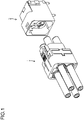
FIG. 1 is a perspective view illustrating a multiple coaxial connector according to a first embodiment. -
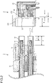
FIG. 2 is a first sectional view illustrating the multiple coaxial connector according to the first embodiment. -
FIG. 3 is a second sectional view illustrating the multiple coaxial connector according to the first embodiment. -
FIG. 4 is a third sectional view illustrating the multiple coaxial connector according to the first embodiment. -
FIG. 5 is a fourth sectional view illustrating the multiple coaxial connector according to the first embodiment. - An embodiment according to the present invention will be described in detail below. Components having the mutually-same functions will be provided with the same reference numerals and the duplicate description thereof will be omitted.
- A structure of a multiple coaxial connector according to a first embodiment will now be described with reference to
FIGs. 1 and2 . As illustrated inFIG. 1 , the multiple coaxial connector according to the present embodiment includes aplug 1 and areceptacle 2 that is connected with theplug 1. - As illustrated in
FIG. 2 , theplug 1 includes ahousing 11, a plurality ofplug shells 12, a plurality ofplug bodies 13, and a plurality ofplug contacts 14. Theplug shells 12 are accommodated in thehousing 11 in a manner to protrude from thehousing 11 by a predetermined length A. Theplug bodies 13 are accommodated inrespective plug shells 12. Theplug contacts 14 are fixed torespective plug bodies 13. Thehousing 11 and theplug bodies 13 are made of an insulation material. Theplug shells 12 and theplug contacts 14 are made of a conductor material. - The
receptacle 2 includes areceptacle shell 21, areceptacle body 22, and areceptacle contact 23. Thereceptacle body 22 is made of an insulation material. Thereceptacle shell 21 and thereceptacle contact 23 are made of a conductor material. - The
receptacle shell 21 includes anaccommodation portion 211, a plurality of throughholes 212, and a plurality ofguide holes 213. Theaccommodation portion 211 entirely accommodates ends of the plurality ofplug shells 12 protruding from thehousing 11 in connector insertion, and the insertion-direction length B of theaccommodation portion 211 satisfies B < A (the reason will be described later). In connector fitting, theaccommodation portion 211 accommodates part of thehousing 11 without any gaps. Theplug shells 12 are inserted into respective throughholes 212. Theguide hole 213 is positioned between theaccommodation portion 211 and the throughhole 212 and communicates theaccommodation portion 211 and the throughhole 212 to each other. Theguide hole 213 is formed in a manner to taper from theaccommodation portion 211 toward the throughhole 212. Theguide hole 213 is preferably formed in a cone trapezoidal shape. - The
receptacle body 22 is accommodated in each throughhole 212. Thereceptacle contact 23 is fixed to thereceptacle body 22, and is fitted to theplug contacts 14 in connector fitting. - When C denotes an insertion-direction length of the
guide hole 213 and T denotes a predetermined threshold value, it is preferable to form thereceptacle shell 21 to satisfy |B+C-A| ≤ T (the reason will be described later). - Further, the end of the
receptacle contact 23 is accommodated in the throughholes 212 or theguide holes 213 as illustrated inFIG. 2 . It is preferable to form the multiple coaxial connector so that a relation between an insertion-direction length D from the end of theplug contact 14 to the end of theplug shell 12 and an insertion-direction length E from the end of thereceptacle contact 23 to the end of thereceptacle body 22 satisfies D-E > 0 (the reason will be described later). - The multiple coaxial connector is formed to satisfy B < A. Accordingly, the end of the
plug shell 12 reaches the innermost portion of theaccommodation portion 211 and is guided by aninclined portion 2131 of theguide hole 213 before thehousing 11 is fitted to theaccommodation portion 211, as illustrated inFIG. 3 .Other plug shells 12 are also guided in a similar manner by otherinclined portions 2131 that are positioned to correspond torespective plug shells 12. Thus, fitting is easily performed even though the connector is a multiple coaxial type. Accordingly, tilt and shaft misalignment correction is performed by theinclined portions 2131 before the fitting between thehousing 11 and theaccommodation portion 211 starts, being able to prevent a large force from being applied to thehousing 11 and theplug shells 12. - |B+C-A|, namely, an absolute value of a value, which is obtained by deducting the protruding length A of the
plug shell 12 from the sum (B+C) of the insertion-direction length B of theaccommodation portion 211 and the insertion-direction length C of theguide hole 213, is set to be equal to the predetermined threshold value T or to be smaller than T. Accordingly, the fitting between thehousing 11 and theaccommodation portion 211 starts at timing when the tilt and shaft misalignment correction by theinclined portions 2131 is almost finished (T > B+C-A > 0), or timing when the correction is just finished (B+C-A = 0), or timing shortly after the correction is finished (-T < B+C-A < 0), being able to prevent a large force from being applied to thehousing 11 and theplug shells 12 as described above. - The end of the
receptacle contact 23 is accommodated in the throughholes 212 or theguide holes 213 and D-E > 0 (that is, D > E) is established. Accordingly, the fitting between theplug shells 12 and thereceptacle body 22 starts before the fitting between theplug contacts 14 and thereceptacle contact 23 starts. The fitting between theplug shells 12 and thereceptacle body 22 corrects distortion caused by tilt and shaft misalignment and the contacts are mutually fitted after the correction, being able to prevent buckling of the contacts. - The
plug contacts 14 and thereceptacle contact 23 are arranged so that the fitting between theplug contacts 14 and thereceptacle contact 23 does not start yet at the start of the fitting between thehousing 11 and theaccommodation portion 211, as illustrated inFIG. 4 . Accordingly, after correction by the guide holes 213 is performed as a first stage and correction by the fitting between thehousing 11 and theaccommodation portion 211 is performed as a second stage, the fitting between theplug contacts 14 and thereceptacle contact 23 starts. Thus, distortion caused by tilt and shaft misalignment is corrected and buckling of the contacts can be prevented.FIG. 5 is a sectional view illustrating a state in which the fitting between theplug contacts 14 and thereceptacle contact 23 is finished. - The foregoing description of the embodiment of the invention has been presented for the purpose of illustration and description. It is not intended to be exhaustive and to limit the invention to the precise form disclosed. Modifications or variations are possible in light of the above teaching. The embodiment was chosen and described to provide the best illustration of the principles of the invention and its practical application, and to enable one of ordinary skill in the art to utilize the invention in various embodiments and with various modifications as are suited to the particular use contemplated. All such modifications and variations are within the scope of the invention as determined by the appended claims when interpreted in accordance with the breadth to which they are fairly, legally, and equitably entitled.
Claims (4)
- A multiple coaxial connector comprising:a plug; anda receptacle that is connected with the plug, whereinthe plug includesa housing,a plurality of plug shells that are accommodated in the housing in a manner to protrude from the housing by a predetermined length A,a plurality of plug bodies that are accommodated in the plug shells respectively, anda plurality of plug contacts that are fixed to the plug bodies respectively, andthe receptacle includes
a receptacle shell that includesan accommodation portion that entirely accommodates ends of the plurality of plug shells, the plug shells protruding from the housing, in connector insertion and whose insertion-direction length B satisfies B < A,a plurality of through holes in which the plug shells are inserted respectively, anda guide hole that is positioned between the accommodation portion and the through holes and communicates the accommodation portion and the through holes to each other, and is formed in a manner to taper from the accommodation portion toward the through holes,a receptacle body that is accommodated in each of the through holes, anda receptacle contact that is fixed to the receptacle body and is to be fitted to the plug contacts. - The multiple coaxial connector according to Claim 1, wherein the receptacle shell is formed so as to satisfy |B+C-A| ≤ T when C denotes an insertion-direction length of the guide hole and T denotes a predetermined threshold value.
- The multiple coaxial connector according to Claim 1 or 2, wherein the guide hole has a cone trapezoidal shape.
- The multiple coaxial connector according to any one of Claims 1 to 3, wherein an end of the receptacle contact is accommodated in the through holes or the guide hole, and a relation between an insertion-direction length D from ends of the plug contacts to the ends of the plug shells and an insertion-direction length E from the end of the receptacle contact to an end of the receptacle body satisfies D-E > 0.
Applications Claiming Priority (1)
| Application Number | Priority Date | Filing Date | Title |
|---|---|---|---|
| JP2021087501A JP7518795B2 (en) | 2021-05-25 | 2021-05-25 | Multi-coaxial connector |
Publications (2)
| Publication Number | Publication Date |
|---|---|
| EP4096031A1 true EP4096031A1 (en) | 2022-11-30 |
| EP4096031B1 EP4096031B1 (en) | 2023-08-23 |
Family
ID=81325520
Family Applications (1)
| Application Number | Title | Priority Date | Filing Date |
|---|---|---|---|
| EP22166782.7A Active EP4096031B1 (en) | 2021-05-25 | 2022-04-05 | Multiple coaxial connector system |
Country Status (4)
| Country | Link |
|---|---|
| US (1) | US12199389B2 (en) |
| EP (1) | EP4096031B1 (en) |
| JP (1) | JP7518795B2 (en) |
| CN (1) | CN115395326A (en) |
Families Citing this family (1)
| Publication number | Priority date | Publication date | Assignee | Title |
|---|---|---|---|---|
| USD1040107S1 (en) * | 2021-09-27 | 2024-08-27 | Smk Corporation | Electrical connector |
Citations (4)
| Publication number | Priority date | Publication date | Assignee | Title |
|---|---|---|---|---|
| US8956169B2 (en) * | 2012-09-12 | 2015-02-17 | Hypertronics Corporation | Self-adjusting coaxial contact |
| US20180366843A1 (en) * | 2017-06-16 | 2018-12-20 | Hirose Electric Co., Ltd. | Coaxial connector assembly |
| CN211208800U (en) * | 2019-09-27 | 2020-08-07 | 嘉兴翼波电子有限公司 | Multi-port fast-plugging drift radio frequency coaxial connector |
| JP2021012847A (en) | 2019-07-09 | 2021-02-04 | 住友電装株式会社 | connector |
Family Cites Families (6)
| Publication number | Priority date | Publication date | Assignee | Title |
|---|---|---|---|---|
| US4697859A (en) * | 1986-08-15 | 1987-10-06 | Amp Incorporated | Floating coaxial connector |
| JP3275141B2 (en) * | 1998-11-04 | 2002-04-15 | 日本航空電子工業株式会社 | Multi-core coaxial connector |
| CN101217223A (en) * | 2007-01-04 | 2008-07-09 | 南京依纳科技有限公司 | Small RF coaxial connector |
| US7481673B1 (en) * | 2008-05-07 | 2009-01-27 | Jinliang Qu | Airtight RF coaxial connector with self-locking by snap-fastening |
| JP5799965B2 (en) * | 2013-01-17 | 2015-10-28 | Smk株式会社 | Floating connector |
| EP3516744A4 (en) * | 2016-09-20 | 2020-05-13 | Commscope Technologies LLC | RIGHT ANGLE COAXIAL CONNECTOR ARRANGEMENT |
-
2021
- 2021-05-25 JP JP2021087501A patent/JP7518795B2/en active Active
-
2022
- 2022-04-05 EP EP22166782.7A patent/EP4096031B1/en active Active
- 2022-05-16 US US17/745,222 patent/US12199389B2/en active Active
- 2022-05-18 CN CN202210544404.1A patent/CN115395326A/en active Pending
Patent Citations (4)
| Publication number | Priority date | Publication date | Assignee | Title |
|---|---|---|---|---|
| US8956169B2 (en) * | 2012-09-12 | 2015-02-17 | Hypertronics Corporation | Self-adjusting coaxial contact |
| US20180366843A1 (en) * | 2017-06-16 | 2018-12-20 | Hirose Electric Co., Ltd. | Coaxial connector assembly |
| JP2021012847A (en) | 2019-07-09 | 2021-02-04 | 住友電装株式会社 | connector |
| CN211208800U (en) * | 2019-09-27 | 2020-08-07 | 嘉兴翼波电子有限公司 | Multi-port fast-plugging drift radio frequency coaxial connector |
Also Published As
| Publication number | Publication date |
|---|---|
| CN115395326A (en) | 2022-11-25 |
| JP7518795B2 (en) | 2024-07-18 |
| US20220385006A1 (en) | 2022-12-01 |
| US12199389B2 (en) | 2025-01-14 |
| EP4096031B1 (en) | 2023-08-23 |
| JP2022180803A (en) | 2022-12-07 |
Similar Documents
| Publication | Publication Date | Title |
|---|---|---|
| US7086898B2 (en) | Coaxial cable Y-splitter assembly with an integral splitter body and method | |
| CA2228693C (en) | Coaxial connector socket | |
| US8727807B2 (en) | Coaxial connector | |
| EP2587591A1 (en) | Coaxial connector | |
| US5791939A (en) | Shielded connector | |
| US10707595B2 (en) | Multi-pin connector block assembly | |
| GB1154181A (en) | Coaxial Cable Connector | |
| EP4096031B1 (en) | Multiple coaxial connector system | |
| KR102627870B1 (en) | Connector assembly | |
| CA2515415A1 (en) | Circuit board and socket assembly | |
| EP3032658B1 (en) | Earphone socket, earphone plug, earphone and electronic device | |
| EP3273546B1 (en) | Plug insert with positioning element | |
| TW201347319A (en) | Coaxial connector | |
| EP3105822B1 (en) | Coaxial cable and connector with dielectric spacer that inhibits unwanted solder flow | |
| US5910347A (en) | Precision molded cylinders | |
| US6894224B2 (en) | Waterproof plug for waterproof connector | |
| EP0006343A1 (en) | Plug and receptacle connectors | |
| CN211404798U (en) | Waterproof integrated connector | |
| US11646524B2 (en) | Cable connector and method for manufacturing cable connector | |
| CN109193280B (en) | Connector with a plurality of connectors | |
| EP4322343A3 (en) | Assembly method for a printed circuit board electrical connector | |
| JP7703088B1 (en) | connector | |
| US20220013959A1 (en) | Manufacturing system for fitted body | |
| US20260135323A1 (en) | Multi-Piece Electrical Connector | |
| US9748714B1 (en) | Reinforced USB socket |
Legal Events
| Date | Code | Title | Description |
|---|---|---|---|
| PUAI | Public reference made under article 153(3) epc to a published international application that has entered the european phase |
Free format text: ORIGINAL CODE: 0009012 |
|
| STAA | Information on the status of an ep patent application or granted ep patent |
Free format text: STATUS: THE APPLICATION HAS BEEN PUBLISHED |
|
| AK | Designated contracting states |
Kind code of ref document: A1 Designated state(s): AL AT BE BG CH CY CZ DE DK EE ES FI FR GB GR HR HU IE IS IT LI LT LU LV MC MK MT NL NO PL PT RO RS SE SI SK SM TR |
|
| STAA | Information on the status of an ep patent application or granted ep patent |
Free format text: STATUS: REQUEST FOR EXAMINATION WAS MADE |
|
| 17P | Request for examination filed |
Effective date: 20221130 |
|
| RBV | Designated contracting states (corrected) |
Designated state(s): AL AT BE BG CH CY CZ DE DK EE ES FI FR GB GR HR HU IE IS IT LI LT LU LV MC MK MT NL NO PL PT RO RS SE SI SK SM TR |
|
| GRAP | Despatch of communication of intention to grant a patent |
Free format text: ORIGINAL CODE: EPIDOSNIGR1 |
|
| STAA | Information on the status of an ep patent application or granted ep patent |
Free format text: STATUS: GRANT OF PATENT IS INTENDED |
|
| RIC1 | Information provided on ipc code assigned before grant |
Ipc: H01R 24/50 20110101ALN20230214BHEP Ipc: H01R 24/40 20110101ALI20230214BHEP Ipc: H01R 13/631 20060101AFI20230214BHEP |
|
| RIN1 | Information on inventor provided before grant (corrected) |
Inventor name: IWAMOTO, YUTA |
|
| RIC1 | Information provided on ipc code assigned before grant |
Ipc: H01R 24/50 20110101ALN20230222BHEP Ipc: H01R 24/40 20110101ALI20230222BHEP Ipc: H01R 13/631 20060101AFI20230222BHEP |
|
| INTG | Intention to grant announced |
Effective date: 20230313 |
|
| GRAS | Grant fee paid |
Free format text: ORIGINAL CODE: EPIDOSNIGR3 |
|
| GRAA | (expected) grant |
Free format text: ORIGINAL CODE: 0009210 |
|
| STAA | Information on the status of an ep patent application or granted ep patent |
Free format text: STATUS: THE PATENT HAS BEEN GRANTED |
|
| AK | Designated contracting states |
Kind code of ref document: B1 Designated state(s): AL AT BE BG CH CY CZ DE DK EE ES FI FR GB GR HR HU IE IS IT LI LT LU LV MC MK MT NL NO PL PT RO RS SE SI SK SM TR |
|
| REG | Reference to a national code |
Ref country code: GB Ref legal event code: FG4D |
|
| REG | Reference to a national code |
Ref country code: CH Ref legal event code: EP |
|
| REG | Reference to a national code |
Ref country code: IE Ref legal event code: FG4D |
|
| REG | Reference to a national code |
Ref country code: DE Ref legal event code: R096 Ref document number: 602022000364 Country of ref document: DE |
|
| REG | Reference to a national code |
Ref country code: LT Ref legal event code: MG9D |
|
| REG | Reference to a national code |
Ref country code: NL Ref legal event code: MP Effective date: 20230823 |
|
| REG | Reference to a national code |
Ref country code: AT Ref legal event code: MK05 Ref document number: 1603690 Country of ref document: AT Kind code of ref document: T Effective date: 20230823 |
|
| PG25 | Lapsed in a contracting state [announced via postgrant information from national office to epo] |
Ref country code: GR Free format text: LAPSE BECAUSE OF FAILURE TO SUBMIT A TRANSLATION OF THE DESCRIPTION OR TO PAY THE FEE WITHIN THE PRESCRIBED TIME-LIMIT Effective date: 20231124 |
|
| PG25 | Lapsed in a contracting state [announced via postgrant information from national office to epo] |
Ref country code: IS Free format text: LAPSE BECAUSE OF FAILURE TO SUBMIT A TRANSLATION OF THE DESCRIPTION OR TO PAY THE FEE WITHIN THE PRESCRIBED TIME-LIMIT Effective date: 20231223 |
|
| PG25 | Lapsed in a contracting state [announced via postgrant information from national office to epo] |
Ref country code: SE Free format text: LAPSE BECAUSE OF FAILURE TO SUBMIT A TRANSLATION OF THE DESCRIPTION OR TO PAY THE FEE WITHIN THE PRESCRIBED TIME-LIMIT Effective date: 20230823 Ref country code: RS Free format text: LAPSE BECAUSE OF FAILURE TO SUBMIT A TRANSLATION OF THE DESCRIPTION OR TO PAY THE FEE WITHIN THE PRESCRIBED TIME-LIMIT Effective date: 20230823 Ref country code: PT Free format text: LAPSE BECAUSE OF FAILURE TO SUBMIT A TRANSLATION OF THE DESCRIPTION OR TO PAY THE FEE WITHIN THE PRESCRIBED TIME-LIMIT Effective date: 20231226 Ref country code: NO Free format text: LAPSE BECAUSE OF FAILURE TO SUBMIT A TRANSLATION OF THE DESCRIPTION OR TO PAY THE FEE WITHIN THE PRESCRIBED TIME-LIMIT Effective date: 20231123 Ref country code: NL Free format text: LAPSE BECAUSE OF FAILURE TO SUBMIT A TRANSLATION OF THE DESCRIPTION OR TO PAY THE FEE WITHIN THE PRESCRIBED TIME-LIMIT Effective date: 20230823 Ref country code: LV Free format text: LAPSE BECAUSE OF FAILURE TO SUBMIT A TRANSLATION OF THE DESCRIPTION OR TO PAY THE FEE WITHIN THE PRESCRIBED TIME-LIMIT Effective date: 20230823 Ref country code: LT Free format text: LAPSE BECAUSE OF FAILURE TO SUBMIT A TRANSLATION OF THE DESCRIPTION OR TO PAY THE FEE WITHIN THE PRESCRIBED TIME-LIMIT Effective date: 20230823 Ref country code: IS Free format text: LAPSE BECAUSE OF FAILURE TO SUBMIT A TRANSLATION OF THE DESCRIPTION OR TO PAY THE FEE WITHIN THE PRESCRIBED TIME-LIMIT Effective date: 20231223 Ref country code: HR Free format text: LAPSE BECAUSE OF FAILURE TO SUBMIT A TRANSLATION OF THE DESCRIPTION OR TO PAY THE FEE WITHIN THE PRESCRIBED TIME-LIMIT Effective date: 20230823 Ref country code: GR Free format text: LAPSE BECAUSE OF FAILURE TO SUBMIT A TRANSLATION OF THE DESCRIPTION OR TO PAY THE FEE WITHIN THE PRESCRIBED TIME-LIMIT Effective date: 20231124 Ref country code: FI Free format text: LAPSE BECAUSE OF FAILURE TO SUBMIT A TRANSLATION OF THE DESCRIPTION OR TO PAY THE FEE WITHIN THE PRESCRIBED TIME-LIMIT Effective date: 20230823 Ref country code: AT Free format text: LAPSE BECAUSE OF FAILURE TO SUBMIT A TRANSLATION OF THE DESCRIPTION OR TO PAY THE FEE WITHIN THE PRESCRIBED TIME-LIMIT Effective date: 20230823 |
|
| PG25 | Lapsed in a contracting state [announced via postgrant information from national office to epo] |
Ref country code: PL Free format text: LAPSE BECAUSE OF FAILURE TO SUBMIT A TRANSLATION OF THE DESCRIPTION OR TO PAY THE FEE WITHIN THE PRESCRIBED TIME-LIMIT Effective date: 20230823 |
|
| PG25 | Lapsed in a contracting state [announced via postgrant information from national office to epo] |
Ref country code: ES Free format text: LAPSE BECAUSE OF FAILURE TO SUBMIT A TRANSLATION OF THE DESCRIPTION OR TO PAY THE FEE WITHIN THE PRESCRIBED TIME-LIMIT Effective date: 20230823 |
|
| PG25 | Lapsed in a contracting state [announced via postgrant information from national office to epo] |
Ref country code: SM Free format text: LAPSE BECAUSE OF FAILURE TO SUBMIT A TRANSLATION OF THE DESCRIPTION OR TO PAY THE FEE WITHIN THE PRESCRIBED TIME-LIMIT Effective date: 20230823 Ref country code: RO Free format text: LAPSE BECAUSE OF FAILURE TO SUBMIT A TRANSLATION OF THE DESCRIPTION OR TO PAY THE FEE WITHIN THE PRESCRIBED TIME-LIMIT Effective date: 20230823 Ref country code: ES Free format text: LAPSE BECAUSE OF FAILURE TO SUBMIT A TRANSLATION OF THE DESCRIPTION OR TO PAY THE FEE WITHIN THE PRESCRIBED TIME-LIMIT Effective date: 20230823 Ref country code: EE Free format text: LAPSE BECAUSE OF FAILURE TO SUBMIT A TRANSLATION OF THE DESCRIPTION OR TO PAY THE FEE WITHIN THE PRESCRIBED TIME-LIMIT Effective date: 20230823 Ref country code: DK Free format text: LAPSE BECAUSE OF FAILURE TO SUBMIT A TRANSLATION OF THE DESCRIPTION OR TO PAY THE FEE WITHIN THE PRESCRIBED TIME-LIMIT Effective date: 20230823 Ref country code: CZ Free format text: LAPSE BECAUSE OF FAILURE TO SUBMIT A TRANSLATION OF THE DESCRIPTION OR TO PAY THE FEE WITHIN THE PRESCRIBED TIME-LIMIT Effective date: 20230823 Ref country code: SK Free format text: LAPSE BECAUSE OF FAILURE TO SUBMIT A TRANSLATION OF THE DESCRIPTION OR TO PAY THE FEE WITHIN THE PRESCRIBED TIME-LIMIT Effective date: 20230823 |
|
| REG | Reference to a national code |
Ref country code: DE Ref legal event code: R097 Ref document number: 602022000364 Country of ref document: DE |
|
| PG25 | Lapsed in a contracting state [announced via postgrant information from national office to epo] |
Ref country code: IT Free format text: LAPSE BECAUSE OF FAILURE TO SUBMIT A TRANSLATION OF THE DESCRIPTION OR TO PAY THE FEE WITHIN THE PRESCRIBED TIME-LIMIT Effective date: 20230823 |
|
| PLBE | No opposition filed within time limit |
Free format text: ORIGINAL CODE: 0009261 |
|
| STAA | Information on the status of an ep patent application or granted ep patent |
Free format text: STATUS: NO OPPOSITION FILED WITHIN TIME LIMIT |
|
| 26N | No opposition filed |
Effective date: 20240524 |
|
| PG25 | Lapsed in a contracting state [announced via postgrant information from national office to epo] |
Ref country code: SI Free format text: LAPSE BECAUSE OF FAILURE TO SUBMIT A TRANSLATION OF THE DESCRIPTION OR TO PAY THE FEE WITHIN THE PRESCRIBED TIME-LIMIT Effective date: 20230823 |
|
| PG25 | Lapsed in a contracting state [announced via postgrant information from national office to epo] |
Ref country code: BG Free format text: LAPSE BECAUSE OF FAILURE TO SUBMIT A TRANSLATION OF THE DESCRIPTION OR TO PAY THE FEE WITHIN THE PRESCRIBED TIME-LIMIT Effective date: 20230823 |
|
| PG25 | Lapsed in a contracting state [announced via postgrant information from national office to epo] |
Ref country code: MC Free format text: LAPSE BECAUSE OF FAILURE TO SUBMIT A TRANSLATION OF THE DESCRIPTION OR TO PAY THE FEE WITHIN THE PRESCRIBED TIME-LIMIT Effective date: 20230823 |
|
| PG25 | Lapsed in a contracting state [announced via postgrant information from national office to epo] |
Ref country code: MC Free format text: LAPSE BECAUSE OF FAILURE TO SUBMIT A TRANSLATION OF THE DESCRIPTION OR TO PAY THE FEE WITHIN THE PRESCRIBED TIME-LIMIT Effective date: 20230823 Ref country code: BG Free format text: LAPSE BECAUSE OF FAILURE TO SUBMIT A TRANSLATION OF THE DESCRIPTION OR TO PAY THE FEE WITHIN THE PRESCRIBED TIME-LIMIT Effective date: 20230823 |
|
| PG25 | Lapsed in a contracting state [announced via postgrant information from national office to epo] |
Ref country code: LU Free format text: LAPSE BECAUSE OF NON-PAYMENT OF DUE FEES Effective date: 20240405 |
|
| REG | Reference to a national code |
Ref country code: BE Ref legal event code: MM Effective date: 20240430 |
|
| PG25 | Lapsed in a contracting state [announced via postgrant information from national office to epo] |
Ref country code: LU Free format text: LAPSE BECAUSE OF NON-PAYMENT OF DUE FEES Effective date: 20240405 |
|
| PG25 | Lapsed in a contracting state [announced via postgrant information from national office to epo] |
Ref country code: BE Free format text: LAPSE BECAUSE OF NON-PAYMENT OF DUE FEES Effective date: 20240430 |
|
| PG25 | Lapsed in a contracting state [announced via postgrant information from national office to epo] |
Ref country code: BE Free format text: LAPSE BECAUSE OF NON-PAYMENT OF DUE FEES Effective date: 20240430 |
|
| PG25 | Lapsed in a contracting state [announced via postgrant information from national office to epo] |
Ref country code: IE Free format text: LAPSE BECAUSE OF NON-PAYMENT OF DUE FEES Effective date: 20240405 |
|
| PGFP | Annual fee paid to national office [announced via postgrant information from national office to epo] |
Ref country code: DE Payment date: 20250430 Year of fee payment: 4 |
|
| PGFP | Annual fee paid to national office [announced via postgrant information from national office to epo] |
Ref country code: FR Payment date: 20250422 Year of fee payment: 4 |
|
| PG25 | Lapsed in a contracting state [announced via postgrant information from national office to epo] |
Ref country code: CY Free format text: LAPSE BECAUSE OF FAILURE TO SUBMIT A TRANSLATION OF THE DESCRIPTION OR TO PAY THE FEE WITHIN THE PRESCRIBED TIME-LIMIT; INVALID AB INITIO Effective date: 20220405 |
|
| REG | Reference to a national code |
Ref country code: CH Ref legal event code: H13 Free format text: ST27 STATUS EVENT CODE: U-0-0-H10-H13 (AS PROVIDED BY THE NATIONAL OFFICE) Effective date: 20251125 |
|
| PG25 | Lapsed in a contracting state [announced via postgrant information from national office to epo] |
Ref country code: TR Free format text: LAPSE BECAUSE OF FAILURE TO SUBMIT A TRANSLATION OF THE DESCRIPTION OR TO PAY THE FEE WITHIN THE PRESCRIBED TIME-LIMIT Effective date: 20230823 |
|
| PG25 | Lapsed in a contracting state [announced via postgrant information from national office to epo] |
Ref country code: CH Free format text: LAPSE BECAUSE OF NON-PAYMENT OF DUE FEES Effective date: 20250430 |