EP4096028A1 - Connector structure including magnet - Google Patents
Connector structure including magnet Download PDFInfo
- Publication number
- EP4096028A1 EP4096028A1 EP21846176.2A EP21846176A EP4096028A1 EP 4096028 A1 EP4096028 A1 EP 4096028A1 EP 21846176 A EP21846176 A EP 21846176A EP 4096028 A1 EP4096028 A1 EP 4096028A1
- Authority
- EP
- European Patent Office
- Prior art keywords
- magnet
- connector
- pole
- connector structure
- mode
- Prior art date
- Legal status (The legal status is an assumption and is not a legal conclusion. Google has not performed a legal analysis and makes no representation as to the accuracy of the status listed.)
- Granted
Links
Images






Classifications
-
- H—ELECTRICITY
- H01—ELECTRIC ELEMENTS
- H01R—ELECTRICALLY-CONDUCTIVE CONNECTIONS; STRUCTURAL ASSOCIATIONS OF A PLURALITY OF MUTUALLY-INSULATED ELECTRICAL CONNECTING ELEMENTS; COUPLING DEVICES; CURRENT COLLECTORS
- H01R13/00—Details of coupling devices of the kinds covered by groups H01R12/70 or H01R24/00 - H01R33/00
- H01R13/62—Means for facilitating engagement or disengagement of coupling parts or for holding them in engagement
- H01R13/6205—Two-part coupling devices held in engagement by a magnet
-
- H—ELECTRICITY
- H01—ELECTRIC ELEMENTS
- H01F—MAGNETS; INDUCTANCES; TRANSFORMERS; SELECTION OF MATERIALS FOR THEIR MAGNETIC PROPERTIES
- H01F7/00—Magnets
- H01F7/02—Permanent magnets [PM]
- H01F7/0231—Magnetic circuits with PM for power or force generation
- H01F7/0252—PM holding devices
-
- H—ELECTRICITY
- H01—ELECTRIC ELEMENTS
- H01F—MAGNETS; INDUCTANCES; TRANSFORMERS; SELECTION OF MATERIALS FOR THEIR MAGNETIC PROPERTIES
- H01F7/00—Magnets
- H01F7/02—Permanent magnets [PM]
- H01F7/04—Means for releasing the attractive force
-
- H—ELECTRICITY
- H01—ELECTRIC ELEMENTS
- H01R—ELECTRICALLY-CONDUCTIVE CONNECTIONS; STRUCTURAL ASSOCIATIONS OF A PLURALITY OF MUTUALLY-INSULATED ELECTRICAL CONNECTING ELEMENTS; COUPLING DEVICES; CURRENT COLLECTORS
- H01R13/00—Details of coupling devices of the kinds covered by groups H01R12/70 or H01R24/00 - H01R33/00
- H01R13/62—Means for facilitating engagement or disengagement of coupling parts or for holding them in engagement
- H01R13/629—Additional means for facilitating engagement or disengagement of coupling parts, e.g. aligning or guiding means, levers, gas pressure electrical locking indicators, manufacturing tolerances
- H01R13/633—Additional means for facilitating engagement or disengagement of coupling parts, e.g. aligning or guiding means, levers, gas pressure electrical locking indicators, manufacturing tolerances for disengagement only
Definitions
- the present invention relates to a connector structure, and more particularly, to a connector structure including a magnet.
- the battery pack may use a connector so as to be separated from an external device according to situation.
- strong force is required to couple or separate the battery pack to/from the external device, and thus, the connector is easily damaged by the strong force.
- the present invention is invented to solve the above-described technical problems, and an object of the present invention is to provide a connector structure in which a male connector and a female connector are easily coupled to each other by using a magnet.
- the connector structure may include a coupling part, a housing, and a first removing tool.
- the coupling part may be coupled to the female connector in a coupling mode and separated from the female connector in a separating mode.
- the housing may include a first magnet on a first surface among surfaces surrounding the coupling part and be configured to attract the female connector by using magnetic force of the first magnet.
- the first removing tool may be configured to rotate a second magnet in the separating mode so as to weaken the magnetic force.
- a connector structure may include a coupling part, a housing, and a removing tool.
- the coupling part may be coupled to the female connector in a coupling mode and separated from the female connector in a separating mode.
- the housing may include a first magnet on a first surface among surfaces surrounding the coupling part and be configured to attract the female connector by using magnetic force of the first magnet.
- the removing tool may be moved closer to the housing in the separating mode and configured to weaken the magnetic force by using the second magnet. In the separating mode, a portion of the second magnet, which faces a portion of the first magnet, may have a polarity different from that of the portion of the first magnet.
- the connector structure (e.g., the male connector) coupled to the female connector may include the magnet.
- the connector structure In the coupling mode, the connector structure may be more easily coupled to the female connector by using the magnetic force of the internal magnet.
- the connector structure In the separating mode, the connector structure may use the magnet of the removing tool to offset the magnetic force. Therefore, the female connector may be separated from the connector structure without being affected by the magnetic force acting in the coupling mode.
- first, second, firstly, or secondly used in various embodiments may modify various elements regardless of their order and/or importance and may not limit the corresponding elements.
- first component may be referred to as the second element, and similarly, the second component may be referred to as the first component without departing from the scope of the present invention.
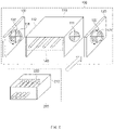
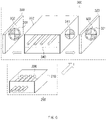
- FIG. 1 is a conceptual view for explaining a method for coupling a connector to a connector structure according to an embodiment of the present invention.
- FIG. 2 is a conceptual view for explaining a method for separating the connector from the connector structure according to an embodiment of the present invention. In order to facilitate understanding of the present invention, FIGS. 1 and 2 will be described together.
- a connector structure 100 may include a housing 110, removing tools 120, 130, and a coupling part 140.
- a connector 200 may include a housing 210 and a coupling part 220.
- the connector structure 100 may be a male connector, and the connector 200 may be a female connector.
- the connector structure 100 may be coupled to or separated from the connector 200 according to an operation mode of the connector structure 100.
- the connector structure 100 may be connected to a battery pack.
- the connector 200 may be connected to internal circuits of various devices such as a vehicle, a portable camera, and a mobile phone.
- the present invention is not limited thereto, and the connector structure 100 may be connected to the internal circuits of the various devices, and the connector 200 may be connected to the battery pack.
- the connector structure 100 or devices connected to the connector 200 may receive power from the connector 200 or the battery pack connected to the connector structure 100.
- the "coupling mode” means an operation mode of the connector structure 100 while the connector 200 is coupled to the connector structure 100.
- the “separating mode” means an operating mode of the connector structure 100 while the connector 200 is separated from the connector structure 100.
- the coupling part 140 may include a plurality of terminals.
- FIG. 1 a structure in which four terminals are provided in the coupling part 140 is illustrated, but the present invention is not limited thereto.
- the coupling part 220 may include a plurality of terminals.
- the number of terminals included in the coupling part 220 may be the same as the number of terminals included in the coupling part 140.
- FIG. 1 a structure in which four terminals are provided in the coupling part 220 is illustrated, but the present invention is not limited thereto.
- the plurality of terminals of the coupling part 140 may be inserted into the plurality of terminals of the coupling part 220.
- current may flow through the plurality of terminals of the coupling part 140 and the coupling part 220.
- the housing 110 may be a structure surrounding the coupling part 140.
- the housing 110 may include the coupling part 140 therein.
- the housing 210 may be a structure surrounding the coupling part 220.
- the housing 210 may include the coupling part 220 therein.
- the housing 210 may be inserted into the housing 110.
- Each of the housings 110 and 210 may be made of an insulating material.
- the housing 110 includes four surfaces.
- a surface facing the removing tool 120 is referred to as a first surface.
- a surface facing the removing tool 130 is referred to as a second surface.
- a surface that is in contact with the bottom is referred to as a third surface.
- the remaining surface is referred to as a fourth side
- the housing 110 may include circular magnets 111 and 112. In FIG. 1 , it is assumed that the housing 110 includes a first circular magnet 111 and a second circular magnet 112 on the first and second surfaces, respectively, but the present invention is not limited thereto.
- the housing 110 may include only one circular magnet or may include two or more circular magnets. Also, when the housing 110 includes one circular magnet, the circular magnet may be disposed on any surface of the four surfaces of the housing 110.
- the circular magnet 112 has substantially the same structure as the circular magnet 111, the circular magnet 111 is mainly described in the following descriptions.
- the circular magnet 111 may include a first pole and a second pole.
- the first pole is an N pole
- the second pole is an S pole
- the first pole is an S pole
- the second pole is an N pole.
- the circular magnet 111 may have a cylindrical shape.
- a height of the cylinder may be less than or equal to a thickness of the first surface of the housing 110.
- the circular magnet 111 may be divided into four quadrants.
- that the circular magnet is divided into specific shapes means that the circular magnet is divided into pillars, each of which has a specific shape.
- the pillar having the specific shape means that a top surface of the pillar has the specific shape. That is, that the circular magnet 111 is divided into the four quadrants means that the circular magnet 111 is divided into four quadrant pillars.
- Each of the quadrants may be a first pole or a second pole. Two quadrants of the quadrants may be the first poles, and the other two quadrants may be the second poles.
- the quadrants adjacent to each other may have different polarities. In the drawings of this specification, portions filled with different patterns indicate different polarities.
- a portion filled with a slash pattern may represent a first pole, and a portion filled with a dot pattern may represent a second pole.
- the present invention is not limited thereto, and the circular magnet 111 may be divided into 2n-divided circles or various shapes.
- 'n' may be a positive number.
- Various embodiments of the circular magnet 111 will be described with reference to FIGS. 4A to 4C .
- Boundary lines dividing the circular magnet 111 may not be parallel to a plane on which the connector structure 100 is placed (or a direction in which the connector 200 approaches the connector structure 100). Since the boundary lines are not disposed parallel to the plane on which the connector structure 100 is placed, greater magnetic force may be applied to the connector 200. However, the present invention is not limited thereto, and the boundary lines dividing the circular magnet 111 may be parallel to the plane on which the connector structure 100 is placed.
- the removing tool 130 has substantially the same structure as the removing tool 120, the removing tool 120 will be mainly described in the following descriptions.
- the removing tool 120 may include a circular magnet 121 and a bearing wheel 122.
- the circular magnet 121 may have substantially the same structure as the circular magnet 111.
- the circular magnet 121 may be disposed to face the circular magnet 111.
- the removing tool 120 may rotate the circular magnet 121 using the bearing wheel 122.
- the removing tool 120 may rotate the circular magnet 121 so that any portion of the circular magnet 121 has the same polarity as a portion of the circular magnet 111 facing the any portion.
- the removing tool 120 may rotate the circular magnet 121 so that any portion of the circular magnet 121 has a polarity different from that of a portion of the circular magnet 111 facing the any portion.
- that have polarities different from each other means that if one side is the first pole, the other side is the second pole.
- the present invention is not limited thereto, and a rectangular magnet having a rectangular parallelepiped shape may be used instead of the circular magnet 121 having the cylindrical shape.
- the circular magnet 121 is replaced with the rectangular magnet
- the remaining circular magnets 111, 112, and 131 may also be replaced with rectangular magnets.
- the rectangular magnet may be a magnet 311b or a magnet 311c of FIGS. 9A and 9B .
- a boundary line dividing the rectangular magnet into the first pole and the second pole may be perpendicular to the plane on which the connector structure 100 is placed.
- the rectangular magnet is fixed to the bearing wheel 122 and may be rotated as the bearing wheel 122 is rotated. This structure will be described with reference to FIG. 5 .
- the removing tool 130 may rotate the circular magnet 131 using the bearing wheel 132.
- the removing tool 130 may rotate the circular magnet 131 so that any portion of the circular magnet 131 has the same polarity as a portion of the circular magnet 112 facing the any portion.
- the removing tool 130 may rotate the circular magnet 131 so that any portion of the circular magnet 131 has a polarity different from that of a portion of the circular magnet 112 facing the any portion.
- magnetic force (specifically, attractive force) generated by the circular magnets 111, 112, 121, and 131 may act on the coupling part 220.
- the coupling part 220 may be a paramagnetic material or a ferromagnetic material.
- the magnetic force may attract the coupling part 220 to the connector structure 100, specifically, the circular magnets 111, 112, 121, and 131. Due to the magnetic force, the device or the user may couple the connector 200 to the connector structure 100 with only weaker force.
- the circular magnets 121 and 131 may weaken and/or offset the magnetic force generated by the circular magnets 111 and 112, respectively.
- the magnetic force due to the circular magnets 111 and 112 may not act on the coupling part 220.
- the device or the user may separate the connector 200 from the connector structure 100 without applying force greater than that in a normal case.
- damage of the connector structure 100 and the connector 200 due to the coupling and separation operations may be minimized.
- FIG. 1 illustrates an operation of the connector structure 100 in the coupling mode.
- a polarity of a portion of the circular magnet 111 and a polarity of a portion facing the portion of the circular magnet 121 are the same.
- the polarity of the circular magnet 112 is not indicated in FIG. 1
- the polarity of the portion of the circular magnet 112 and the polarity of the portion facing the portion of the circular magnet 131 are also the same.
- FIG. 2 illustrates an operation of the connector structure 100 in the separating mode. Referring to FIG. 2 , in the separating mode, a polarity of a portion of the circular magnet 111 is different from that of a portion facing the portion of the circular magnet 121.
- the polarity of the circular magnet 112 is not indicated in FIG. 2
- the polarity of the portion of the circular magnet 112 and the polarity of the portion facing the portion of the circular magnet 131 are also different from each other.
- the connector structure 100 has been described as rotating the circular magnets 121 and 131 in the coupling mode and the separating mode, but the present invention is not limited thereto.
- the connector structure 100 may rotate the circular magnets 111 and 112 instead of the circular magnets 121 and 131 in the coupling mode and the separating mode to adjust the magnetic force acting on the connector 200 as described above.
- both the circular magnets 121 and 131 and the circular magnets 111 and 112 may be rotated.
- the connector structure 100 may include a bearing wheel surrounding each of the circular magnets 111 and 112.
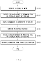
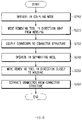
- FIG. 3 is a flowchart for explaining an operation of the connector structure 100 of FIG. 1 .
- the connector structure 100 and the connector 200 of FIG. 1 may operate in a coupling mode.
- the connector structure 100 may rotate the circular magnets 121, 131 of the removing tools 120, 130 and/or the circular magnets 111, 112 of the housing 110. As described with reference to FIG. 1 , the connector structure 100 may rotate the circular magnet 121 and/or the circular magnet 111 so that any portion of the circular magnet 121 has the same polarity as a portion of the circular magnet 111 facing the any portion. The connector structure 100 may rotate the circular magnet 131 and/or the circular magnet 113 so that so that any portion of the circular magnet 131 has the same polarity as a portion of the circular magnet 112 facing the any portion. Thus, the connector 200 may receive attractive force to the connector structure 100 by the magnetic force generated by the circular magnets 111, 112, 121, and 131.
- the connector 200 may be more easily coupled to the connector structure 100 by manpower.
- the connector structure 100 and the connector 200 may operate in a separating mode.
- the connector structure 100 may rotate the circular magnets 121, 131 of the removing tools 120, 130 and/or the circular magnets 111, 112 of the housing 110. As described with reference to FIG. 1 , the connector structure 100 may rotate the circular magnet 121 and/or the circular magnet 111 so that a polarity of any portion of the circular magnet 121 and a polarity of a portion of the circular magnet 111 facing the any portion are different from each other. The connector structure 100 may rotate the circular magnet 131 and/or the circular magnet 113 so that so that a polarity of any portion of the circular magnet 131 and a polarity of a portion of the circular magnet 112 facing the any portion are different from each other. Thus, the magnetic force acting on the connector 200 in the coupling mode may be removed.
- the connector 200 may be removed from the connector structure 100 without larger force.
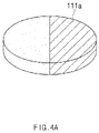
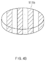
- FIGS. 4A to 4C are conceptual views illustrating various embodiments of the circular magnet 111 of FIG. 1 .
- the circular magnet 111 of FIG. 1 may be replaced with one of the circular magnets 111a, 111b, 111c of FIGS. 4C to 4C and may also be replaced with a circular magnet having the features of the present invention, which are disclosed in this specification. Correspondingly, not only the circular magnet 111 but also the other circular magnets 112, 121, and 131 may be replaced.
- the circular magnet 111a may be divided into two semicircles.
- a boundary line between the semicircles may be a line, which is perpendicular to a horizontal line, or an inclined line.
- the horizontal line means a line parallel to the plane on which the connector structure 100 of FIG. 1 is placed.
- One of the two semicircles may be a first pole, and the other may be a second pole.
- the circular magnet 111b may be divided into 2m sections by 2m-1 lines.
- 'm' is a positive number.
- 'm' may be 4.
- the 2m-1 lines may be lines inclined at the same angle with respect to the horizontal line.
- the 2m sections may be the first pole or the second pole. Specifically, the sections adjacent to each other among the 2m sections may have different polarities.
- the circular magnet 111c may be divided into 2n-divided circles by n lines.
- 'n' is a positive number, and referring to FIG. 4C , 'n' may be 3.
- the n lines may be lines passing through an origin point.
- Each of the 2n-divided circles may be the first pole or the second pole.
- 2n 2n-divided circles adjacent to each other among the 2n-divided circles may have different polarities.
- FIG. 5 is a conceptual view of a removing tool including a rectangular magnet according to an embodiment of the present invention.
- the removing tool 120 of FIG. 1 may include a rectangular magnet 121' having a rectangular parallelepiped shape instead of the circular magnet 121 having the cylindrical shape.
- the rectangular magnet 121' is fixed to the bearing wheel 122 and may be rotated as the bearing wheel 122 is rotated. That is, the present invention may adjust magnetic force acting on the connector 200 of FIG. 1 in the coupling mode and the separating mode by rotating the rectangular magnet 121'.
- FIG. 6 is a conceptual view for explaining a method for coupling a connector to a connector structure according to another embodiment of the present invention.
- FIG. 7 is a conceptual view for explaining a method for separating the connector from the connector structure according to another embodiment of the present invention. In order to facilitate understanding of the present invention, FIGS. 6 and 7 will be described together.
- Configurations 310, 320, 330, and 340 of the connector structure 300 illustrated in FIGS. 6 and 7 may provide operations similar to those of the configurations 110, 120, 130, and 140 of the connector structure 100 illustrated in FIGS. 1 and 2 , respectively.
- the duplicated descriptions will be omitted, and the difference between the connector structure 300 and the connector structure 100 will be mainly described.
- a connector structure 300 may include a housing 310, removing tools 320 and 330, and a coupling part 340.
- the connector structure 300 may be coupled to or separated from the connector 200 according to an operation mode.
- the connector structure 300 may be a male connector
- the connector 200 may be a female connector.
- the connector structure 300 may move the removing tools 320 and 330 without rotating the magnets 311, 312, 321, and 331 to adjust magnetic force acting on the connector 200.
- the magnets 321 and 331 may be disposed on the removing tools 320 and 330 so that any portions of the magnets 321 and 331 have the same polarity as portions of the magnets 311 and 312 facing the any portions, respectively.
- the magnets 311, 312, 321, and 331 may be various types of magnets.
- Each of the magnets 311, 312, 321, and 331 may be a rectangular magnet having a rectangular parallelepiped shape, and various embodiments of the rectangular magnet will be described with reference to FIGS. 9B and 9C .
- the present invention is not limited thereto, and the connector structure 300 may rotate the magnets 311, 312, 321, and 331 and move the removing tools 320 and 330 to adjust the magnetic force acting on the connector 200.
- the magnets 321 and 331 are disposed on the removing tools 320 and 330 so that any portions of the magnets 321 and 331 have the same polarity as portions of the magnets 311 and 312 facing the any portions, respectively.
- the connector structure 300 may move removing tools 320 and 330 in a direction that is away from housing 310.
- the magnetic force generated by the magnets 311 and 312 may be stronger than the magnetic force generated by the magnets 321 and 331 on the connector 200.
- the connector 200 may receive attractive force to the connector structure 300 by the magnetic force generated by the magnets 311 and 312. Due to the magnetic force, the device or the user may couple the connector 200 to the connector structure 300 with only weaker force.
- the connector structure 300 may move the removing tools 320 and 330 in a direction that is closer to the housing 310.
- the magnetic force of the magnets 321 and 331 acting on the connector 200 may be weakened and/or offset by the magnets 311 and 312.
- the device or the user may separate the connector 200 from the connector structure 300 without applying force greater than that in a normal case.
- damage of the connector structure 300 and the connector 200 due to the coupling and separation operations may be minimized.
- FIG. 6 illustrates an operation of the connector structure 300 in the coupling mode.
- FIG. 7 illustrates an operation of the connector structure 300 in the separating mode. Comparing FIGS. 6 and 7 , it is confirmed that the removing tools 320 and 330 are disposed closer to the housing 310 in the separating mode rather than in the coupling mode.
- FIG. 8 is a flowchart for explaining an operation of the connector structure 300 of FIG. 6 .
- the connector structure 300 and the connector 200 of FIG. 6 may operate in a coupling mode.
- the connector structure 300 may move removing tools 320 and 330 in a direction that is away from housing 310.
- the connector 200 may receive attractive force to the connector structure 300 by the magnetic force generated by the magnets 112 and 121.
- the connector 200 may be more easily coupled to the connector structure 300 by manpower.
- the connector structure 300 and the connector 200 may operate in a separating mode.
- the connector structure 300 may move the removing tools 320 and 330 in a direction that is closer to the housing 310.
- the magnetic force of the magnets 112 and 121 may be offset by the magnets 321 and 331 to remove the attractive force acting on the connector 200.
- the connector 200 may be removed from the connector structure 300 without larger force.
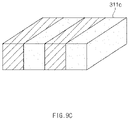
- FIGS. 9A to 9C are conceptual views illustrating various embodiments of a magnet 311 of FIG. 6 .
- the magnet 511 of FIG. 6 may be replaced with one of magnets 311a, 311b, 311c of FIGS. 9A to 9C and may also be replaced with a magnet having the features of the present invention, which are disclosed in this specification.
- the magnet 511 may be replaced with one of the magnet 111 of FIG. 1 and the magnets 111a, 111b, and 111c of FIG. 4 .
- the magnet 311 as well as the other magnets 312, 321, and 331 may be replaced.
- the magnet 311a may be a circular magnet.
- the magnet 311a may be divided into a single circle and a ring surrounding the circle.
- the magnet 321 may also be divided into a single circle and a ring surrounding the circle.
- the circle portion and the ring portion of the magnet 311a when the circle portion and the ring portion of the magnet 311a are the first pole and the second pole, respectively, the circle portion and the ring portion of the magnet 321 may be the second pole and the first pole, respectively.
- the circle portion and the ring portion of the magnet 311a are the second pole and the first pole, respectively, the circle portion and the ring portion of the magnet 321 may be the first pole and the second pole, respectively.
- Each of the magnet 311b and the magnet 311c may be a rectangular magnet.
- the rectangular magnet may be divided into 2k rectangles by 2k-1 lines.
- 'k' is a positive number.
- 'k' may be 1, and referring to FIG. 9C , 'k' may be 2.
- the 2k-1 lines may be lines perpendicular to a plane on which the connector structure 300 is placed.
- Each of the 2k rectangles may be the first pole or the second pole. Specifically, the rectangles among the 2k rectangles may have different polarities.
Landscapes
- Physics & Mathematics (AREA)
- Electromagnetism (AREA)
- Engineering & Computer Science (AREA)
- Power Engineering (AREA)
- Details Of Connecting Devices For Male And Female Coupling (AREA)
Abstract
Description
- This application claims the priority of
Korean Patent Application No. 10-2020-0091281, filed on July 22, 2020 - The present invention relates to a connector structure, and more particularly, to a connector structure including a magnet.
- Recently, as demands for portable electronic products such as laptops, video cameras, and mobile phones have rapidly increased, and development of electric vehicles, energy storage batteries, robots, satellites, etc. is regularized, studies on high-performance secondary batteries that are repeatedly chargeable and dischargeable are being actively conducted.
- Currently commercialized secondary batteries include nickel cadmium batteries, nickel hydride batteries, nickel zinc batteries, and lithium secondary batteries. Among them, when compared to nickel-based secondary batteries, the lithium secondary batteries are attracting attention because of their advantages such as freedom of charging and discharging, very low self-discharge rate, and high energy density due to almost no memory effect. Since various kinds of combustible materials are embedded in the secondary batteries, there is a risk of heat generation and explosion due to overcharging, overcurrent, and other physical external impacts. Accordingly, the battery pack may use a connector so as to be separated from an external device according to situation. However, there is a problem in that strong force is required to couple or separate the battery pack to/from the external device, and thus, the connector is easily damaged by the strong force.
- The present invention is invented to solve the above-described technical problems, and an object of the present invention is to provide a connector structure in which a male connector and a female connector are easily coupled to each other by using a magnet.
- The connector structure according to an embodiment of the present invention may include a coupling part, a housing, and a first removing tool. The coupling part may be coupled to the female connector in a coupling mode and separated from the female connector in a separating mode. The housing may include a first magnet on a first surface among surfaces surrounding the coupling part and be configured to attract the female connector by using magnetic force of the first magnet. The first removing tool may be configured to rotate a second magnet in the separating mode so as to weaken the magnetic force.
- A connector structure according to another embodiment of the present invention may include a coupling part, a housing, and a removing tool. The coupling part may be coupled to the female connector in a coupling mode and separated from the female connector in a separating mode. The housing may include a first magnet on a first surface among surfaces surrounding the coupling part and be configured to attract the female connector by using magnetic force of the first magnet. The removing tool may be moved closer to the housing in the separating mode and configured to weaken the magnetic force by using the second magnet. In the separating mode, a portion of the second magnet, which faces a portion of the first magnet, may have a polarity different from that of the portion of the first magnet.
- According to the embodiment of the present invention, the connector structure (e.g., the male connector) coupled to the female connector may include the magnet. In the coupling mode, the connector structure may be more easily coupled to the female connector by using the magnetic force of the internal magnet. In the separating mode, the connector structure may use the magnet of the removing tool to offset the magnetic force. Therefore, the female connector may be separated from the connector structure without being affected by the magnetic force acting in the coupling mode.
-
-
FIG. 1 is a conceptual view for explaining a method for coupling a connector to a connector structure according to an embodiment of the present invention. -
FIG. 2 is a conceptual view for explaining a method for separating the connector from the connector structure according to an embodiment of the present invention. -
FIG. 3 is a flowchart for explaining an operation of theconnector structure 100 ofFIG. 1 . -
FIGS. 4A to 4C are conceptual views illustrating various embodiments of acircular magnet 111 ofFIG. 1 . -
FIG. 5 is a conceptual view of a removing tool including a rectangular magnet according to an embodiment of the present invention. -
FIG. 6 is a conceptual view for explaining a method for coupling a connector to a connector structure according to another embodiment of the present invention. -
FIG. 7 is a conceptual view for explaining a method for separating the connector from the connector structure according to another embodiment of the present invention. -
FIG. 8 is a flowchart for explaining an operation of theconnector structure 300 ofFIG. 6 . -
FIGS. 9A to 9C are conceptual views illustrating various embodiments of amagnet 311 ofFIG. 6 . - Hereinafter, various embodiments will be described in detail with reference to the accompanying drawings. In this document, same reference numerals are used for the same components in the drawings, and duplicated descriptions of the same components will be omitted.
- For the various embodiments of the present invention disclosed in this document, specific structural or functional descriptions have been exemplified for the purpose of describing the embodiments of the present invention only, and various embodiments of the present invention may be implemented in various forms and should not be construed as being limited to the embodiments described in this document.
- Expressions such as "first", "second", "firstly", or "secondly" used in various embodiments may modify various elements regardless of their order and/or importance and may not limit the corresponding elements. For example, the first component may be referred to as the second element, and similarly, the second component may be referred to as the first component without departing from the scope of the present invention.
- Terms used in this document are only used to describe a specific embodiment and may not be intended to limit the scope of other embodiments. The terms of a singular form may include plural forms unless referred to the contrary.
- All terms used herein, which include technical or scientific terms, may have the same meaning as commonly understood by one of ordinary skill in the art of the present invention. Terms defined in general used in the dictionary may be interpreted as having the same or similar meaning as the meaning in the context of the related art, and unless explicitly defined in this document, it is not interpreted in an ideal or excessively formal meaning. In some cases, even terms defined in this document may not be construed to exclude embodiments of the present invention.
-
FIG. 1 is a conceptual view for explaining a method for coupling a connector to a connector structure according to an embodiment of the present invention.FIG. 2 is a conceptual view for explaining a method for separating the connector from the connector structure according to an embodiment of the present invention. In order to facilitate understanding of the present invention,FIGS. 1 and2 will be described together. - A
connector structure 100 may include ahousing 110, removingtools coupling part 140. Aconnector 200 may include ahousing 210 and acoupling part 220. For example, theconnector structure 100 may be a male connector, and theconnector 200 may be a female connector. Theconnector structure 100 may be coupled to or separated from theconnector 200 according to an operation mode of theconnector structure 100. - The
connector structure 100 may be connected to a battery pack. In this case, theconnector 200 may be connected to internal circuits of various devices such as a vehicle, a portable camera, and a mobile phone. However, the present invention is not limited thereto, and theconnector structure 100 may be connected to the internal circuits of the various devices, and theconnector 200 may be connected to the battery pack. When theconnector structure 100 and theconnector 200 are coupled to each other, theconnector structure 100 or devices connected to theconnector 200 may receive power from theconnector 200 or the battery pack connected to theconnector structure 100. In the following descriptions, the "coupling mode" means an operation mode of theconnector structure 100 while theconnector 200 is coupled to theconnector structure 100. The "separating mode" means an operating mode of theconnector structure 100 while theconnector 200 is separated from theconnector structure 100. - The
coupling part 140 may include a plurality of terminals. InFIG. 1 , a structure in which four terminals are provided in thecoupling part 140 is illustrated, but the present invention is not limited thereto. - The
coupling part 220 may include a plurality of terminals. The number of terminals included in thecoupling part 220 may be the same as the number of terminals included in thecoupling part 140. InFIG. 1 , a structure in which four terminals are provided in thecoupling part 220 is illustrated, but the present invention is not limited thereto. - When the
connector structure 100 is coupled to theconnector 200, the plurality of terminals of thecoupling part 140 may be inserted into the plurality of terminals of thecoupling part 220. When theconnector structure 100 is coupled to theconnector 200, current may flow through the plurality of terminals of thecoupling part 140 and thecoupling part 220. - The
housing 110 may be a structure surrounding thecoupling part 140. Thehousing 110 may include thecoupling part 140 therein. Thehousing 210 may be a structure surrounding thecoupling part 220. Thehousing 210 may include thecoupling part 220 therein. When theconnector structure 100 is coupled to theconnector 200, thehousing 210 may be inserted into thehousing 110. Each of thehousings - In this specification, it is assumed that the
housing 110 includes four surfaces. Among the four surfaces, a surface facing the removingtool 120 is referred to as a first surface. Among the remaining three surfaces, a surface facing the removingtool 130 is referred to as a second surface. Among the remaining two surfaces, a surface that is in contact with the bottom is referred to as a third surface. The remaining surface is referred to as a fourth side - The
housing 110 may includecircular magnets FIG. 1 , it is assumed that thehousing 110 includes a firstcircular magnet 111 and a secondcircular magnet 112 on the first and second surfaces, respectively, but the present invention is not limited thereto. Thehousing 110 may include only one circular magnet or may include two or more circular magnets. Also, when thehousing 110 includes one circular magnet, the circular magnet may be disposed on any surface of the four surfaces of thehousing 110. - Since the
circular magnet 112 has substantially the same structure as thecircular magnet 111, thecircular magnet 111 is mainly described in the following descriptions. - The
circular magnet 111 may include a first pole and a second pole. When the first pole is an N pole, the second pole is an S pole, and when the first pole is an S pole, the second pole is an N pole. - The
circular magnet 111 may have a cylindrical shape. A height of the cylinder may be less than or equal to a thickness of the first surface of thehousing 110. - The
circular magnet 111 may be divided into four quadrants. In the following descriptions, that the circular magnet is divided into specific shapes means that the circular magnet is divided into pillars, each of which has a specific shape. The pillar having the specific shape means that a top surface of the pillar has the specific shape. That is, that thecircular magnet 111 is divided into the four quadrants means that thecircular magnet 111 is divided into four quadrant pillars. Each of the quadrants may be a first pole or a second pole. Two quadrants of the quadrants may be the first poles, and the other two quadrants may be the second poles. The quadrants adjacent to each other may have different polarities. In the drawings of this specification, portions filled with different patterns indicate different polarities. For example, in thecircular magnet 111, a portion filled with a slash pattern may represent a first pole, and a portion filled with a dot pattern may represent a second pole. However, the present invention is not limited thereto, and thecircular magnet 111 may be divided into 2n-divided circles or various shapes. Here, 'n' may be a positive number. Various embodiments of thecircular magnet 111 will be described with reference toFIGS. 4A to 4C . - Boundary lines dividing the
circular magnet 111 may not be parallel to a plane on which theconnector structure 100 is placed (or a direction in which theconnector 200 approaches the connector structure 100). Since the boundary lines are not disposed parallel to the plane on which theconnector structure 100 is placed, greater magnetic force may be applied to theconnector 200. However, the present invention is not limited thereto, and the boundary lines dividing thecircular magnet 111 may be parallel to the plane on which theconnector structure 100 is placed. - Since the removing
tool 130 has substantially the same structure as the removingtool 120, the removingtool 120 will be mainly described in the following descriptions. - The removing
tool 120 may include acircular magnet 121 and abearing wheel 122. Thecircular magnet 121 may have substantially the same structure as thecircular magnet 111. Thecircular magnet 121 may be disposed to face thecircular magnet 111. - The removing
tool 120 may rotate thecircular magnet 121 using thebearing wheel 122. In the coupling mode, the removingtool 120 may rotate thecircular magnet 121 so that any portion of thecircular magnet 121 has the same polarity as a portion of thecircular magnet 111 facing the any portion. In the separating mode, the removingtool 120 may rotate thecircular magnet 121 so that any portion of thecircular magnet 121 has a polarity different from that of a portion of thecircular magnet 111 facing the any portion. In the following descriptions, that have polarities different from each other means that if one side is the first pole, the other side is the second pole. However, the present invention is not limited thereto, and a rectangular magnet having a rectangular parallelepiped shape may be used instead of thecircular magnet 121 having the cylindrical shape. When thecircular magnet 121 is replaced with the rectangular magnet, the remainingcircular magnets magnet 311b or amagnet 311c ofFIGS. 9A and9B . A boundary line dividing the rectangular magnet into the first pole and the second pole may be perpendicular to the plane on which theconnector structure 100 is placed. In addition, the rectangular magnet is fixed to thebearing wheel 122 and may be rotated as thebearing wheel 122 is rotated. This structure will be described with reference toFIG. 5 . - The removing
tool 130 may rotate thecircular magnet 131 using thebearing wheel 132. In the coupling mode, the removingtool 130 may rotate thecircular magnet 131 so that any portion of thecircular magnet 131 has the same polarity as a portion of thecircular magnet 112 facing the any portion. In the separating mode, the removingtool 130 may rotate thecircular magnet 131 so that any portion of thecircular magnet 131 has a polarity different from that of a portion of thecircular magnet 112 facing the any portion. - In this case, in the coupling mode, magnetic force (specifically, attractive force) generated by the
circular magnets coupling part 220. Thecoupling part 220 may be a paramagnetic material or a ferromagnetic material. Thus, the magnetic force may attract thecoupling part 220 to theconnector structure 100, specifically, thecircular magnets connector 200 to theconnector structure 100 with only weaker force. - In the separating mode, the
circular magnets circular magnets circular magnets coupling part 220. Thus, the device or the user may separate theconnector 200 from theconnector structure 100 without applying force greater than that in a normal case. Thus, damage of theconnector structure 100 and theconnector 200 due to the coupling and separation operations may be minimized. -
FIG. 1 illustrates an operation of theconnector structure 100 in the coupling mode. Referring toFIG. 1 , in the coupling mode, a polarity of a portion of thecircular magnet 111 and a polarity of a portion facing the portion of thecircular magnet 121 are the same. Although the polarity of thecircular magnet 112 is not indicated inFIG. 1 , the polarity of the portion of thecircular magnet 112 and the polarity of the portion facing the portion of thecircular magnet 131 are also the same.FIG. 2 illustrates an operation of theconnector structure 100 in the separating mode. Referring toFIG. 2 , in the separating mode, a polarity of a portion of thecircular magnet 111 is different from that of a portion facing the portion of thecircular magnet 121. Although the polarity of thecircular magnet 112 is not indicated inFIG. 2 , the polarity of the portion of thecircular magnet 112 and the polarity of the portion facing the portion of thecircular magnet 131 are also different from each other. - In the above, the
connector structure 100 has been described as rotating thecircular magnets connector structure 100 may rotate thecircular magnets circular magnets connector 200 as described above. Here, both thecircular magnets circular magnets circular magnets connector structure 100 may include a bearing wheel surrounding each of thecircular magnets -
FIG. 3 is a flowchart for explaining an operation of theconnector structure 100 ofFIG. 1 . - In operation S110, the
connector structure 100 and theconnector 200 ofFIG. 1 may operate in a coupling mode. - In operation S120, the
connector structure 100 may rotate thecircular magnets tools circular magnets housing 110. As described with reference toFIG. 1 , theconnector structure 100 may rotate thecircular magnet 121 and/or thecircular magnet 111 so that any portion of thecircular magnet 121 has the same polarity as a portion of thecircular magnet 111 facing the any portion. Theconnector structure 100 may rotate thecircular magnet 131 and/or the circular magnet 113 so that so that any portion of thecircular magnet 131 has the same polarity as a portion of thecircular magnet 112 facing the any portion. Thus, theconnector 200 may receive attractive force to theconnector structure 100 by the magnetic force generated by thecircular magnets - In operation S130, the
connector 200 may be more easily coupled to theconnector structure 100 by manpower. - In operation S140, the
connector structure 100 and theconnector 200 may operate in a separating mode. - In operation S150, the
connector structure 100 may rotate thecircular magnets tools circular magnets housing 110. As described with reference toFIG. 1 , theconnector structure 100 may rotate thecircular magnet 121 and/or thecircular magnet 111 so that a polarity of any portion of thecircular magnet 121 and a polarity of a portion of thecircular magnet 111 facing the any portion are different from each other. Theconnector structure 100 may rotate thecircular magnet 131 and/or the circular magnet 113 so that so that a polarity of any portion of thecircular magnet 131 and a polarity of a portion of thecircular magnet 112 facing the any portion are different from each other. Thus, the magnetic force acting on theconnector 200 in the coupling mode may be removed. - In operation S160, the
connector 200 may be removed from theconnector structure 100 without larger force. -
FIGS. 4A to 4C are conceptual views illustrating various embodiments of thecircular magnet 111 ofFIG. 1 . - The
circular magnet 111 ofFIG. 1 may be replaced with one of thecircular magnets FIGS. 4C to 4C and may also be replaced with a circular magnet having the features of the present invention, which are disclosed in this specification. Correspondingly, not only thecircular magnet 111 but also the othercircular magnets - The
circular magnet 111a may be divided into two semicircles. A boundary line between the semicircles may be a line, which is perpendicular to a horizontal line, or an inclined line. In the following descriptions, the horizontal line means a line parallel to the plane on which theconnector structure 100 ofFIG. 1 is placed. One of the two semicircles may be a first pole, and the other may be a second pole. - The
circular magnet 111b may be divided into 2m sections by 2m-1 lines. Here, 'm' is a positive number. Referring toFIG. 4B , 'm' may be 4. The 2m-1 lines may be lines inclined at the same angle with respect to the horizontal line. The 2m sections may be the first pole or the second pole. Specifically, the sections adjacent to each other among the 2m sections may have different polarities. - As described with reference to
FIG. 1 , thecircular magnet 111c may be divided into 2n-divided circles by n lines. Here, 'n' is a positive number, and referring toFIG. 4C , 'n' may be 3. The n lines may be lines passing through an origin point. Each of the 2n-divided circles may be the first pole or the second pole. Specifically, 2n 2n-divided circles adjacent to each other among the 2n-divided circles may have different polarities. -
FIG. 5 is a conceptual view of a removing tool including a rectangular magnet according to an embodiment of the present invention. - As described with reference to
FIG. 1 , the removingtool 120 ofFIG. 1 may include a rectangular magnet 121' having a rectangular parallelepiped shape instead of thecircular magnet 121 having the cylindrical shape. As illustrated inFIG. 1 , the rectangular magnet 121' is fixed to thebearing wheel 122 and may be rotated as thebearing wheel 122 is rotated. That is, the present invention may adjust magnetic force acting on theconnector 200 ofFIG. 1 in the coupling mode and the separating mode by rotating the rectangular magnet 121'. -
FIG. 6 is a conceptual view for explaining a method for coupling a connector to a connector structure according to another embodiment of the present invention.FIG. 7 is a conceptual view for explaining a method for separating the connector from the connector structure according to another embodiment of the present invention. In order to facilitate understanding of the present invention,FIGS. 6 and7 will be described together. -
Configurations connector structure 300 illustrated inFIGS. 6 and7 may provide operations similar to those of theconfigurations connector structure 100 illustrated inFIGS. 1 and2 , respectively. Thus, with reference toFIGS. 6 and7 , the duplicated descriptions will be omitted, and the difference between theconnector structure 300 and theconnector structure 100 will be mainly described. - A
connector structure 300 may include a housing 310, removingtools coupling part 340. Theconnector structure 300 may be coupled to or separated from theconnector 200 according to an operation mode. For example, theconnector structure 300 may be a male connector, and theconnector 200 may be a female connector. - The
connector structure 300 may move the removingtools magnets connector 200. In this case, themagnets tools magnets magnets magnets magnets FIGS. 9B and9C . - However, the present invention is not limited thereto, and the
connector structure 300 may rotate themagnets tools connector 200. In this case, it is unnecessary that themagnets tools magnets magnets - In coupling mode, the
connector structure 300 may move removingtools magnets magnets connector 200. Theconnector 200 may receive attractive force to theconnector structure 300 by the magnetic force generated by themagnets connector 200 to theconnector structure 300 with only weaker force. - In the disconnect mode, the
connector structure 300 may move the removingtools magnets connector 200 may be weakened and/or offset by themagnets connector 200 from theconnector structure 300 without applying force greater than that in a normal case. Thus, damage of theconnector structure 300 and theconnector 200 due to the coupling and separation operations may be minimized. -
FIG. 6 illustrates an operation of theconnector structure 300 in the coupling mode.FIG. 7 illustrates an operation of theconnector structure 300 in the separating mode. ComparingFIGS. 6 and7 , it is confirmed that the removingtools -
FIG. 8 is a flowchart for explaining an operation of theconnector structure 300 ofFIG. 6 . - In operation S210, the
connector structure 300 and theconnector 200 ofFIG. 6 may operate in a coupling mode. - In operation S220, the
connector structure 300 may move removingtools connector 200 may receive attractive force to theconnector structure 300 by the magnetic force generated by themagnets - In operation S230, the
connector 200 may be more easily coupled to theconnector structure 300 by manpower. - In operation S240, the
connector structure 300 and theconnector 200 may operate in a separating mode. - In operation S250, the
connector structure 300 may move the removingtools magnets magnets connector 200. - In operation S260, the
connector 200 may be removed from theconnector structure 300 without larger force. -
FIGS. 9A to 9C are conceptual views illustrating various embodiments of amagnet 311 ofFIG. 6 . - The magnet 511 of
FIG. 6 may be replaced with one ofmagnets FIGS. 9A to 9C and may also be replaced with a magnet having the features of the present invention, which are disclosed in this specification. For example, the magnet 511 may be replaced with one of themagnet 111 ofFIG. 1 and themagnets FIG. 4 . Themagnet 311 as well as theother magnets - The
magnet 311a may be a circular magnet. Themagnet 311a may be divided into a single circle and a ring surrounding the circle. Correspondingly, themagnet 321 may also be divided into a single circle and a ring surrounding the circle. In this case, when the circle portion and the ring portion of themagnet 311a are the first pole and the second pole, respectively, the circle portion and the ring portion of themagnet 321 may be the second pole and the first pole, respectively. Also, when the circle portion and the ring portion of themagnet 311a are the second pole and the first pole, respectively, the circle portion and the ring portion of themagnet 321 may be the first pole and the second pole, respectively. - Each of the
magnet 311b and themagnet 311c may be a rectangular magnet. The rectangular magnet may be divided into 2k rectangles by 2k-1 lines. Here, 'k' is a positive number. Referring toFIG. 9B , 'k' may be 1, and referring toFIG. 9C , 'k' may be 2. The 2k-1 lines may be lines perpendicular to a plane on which theconnector structure 300 is placed. Each of the 2k rectangles may be the first pole or the second pole. Specifically, the rectangles among the 2k rectangles may have different polarities. - The above-described contents are specific embodiments for carrying out the present invention. The present invention will include not only the above-described embodiments, but also simple design changes or easily changeable embodiments. In addition, the present invention will include techniques that can be easily modified and implemented using the embodiments. Therefore, the scope of the present invention is defined not by the detailed description of the inventive concept but by the appended claims, and all differences within the scope will be construed as being included in the present invention.
Claims (12)
- A connector structure comprising:a coupling part coupled to a female connector in a coupling mode and separated from the female connector in a separating mode;a housing comprising a first magnet on a first surface among surfaces surrounding the coupling part, the housing being configured to attract the female connector by using magnetic force of the first magnet; anda first removing tool configured to rotate a second magnet in the separating mode to weaken the magnetic force.
- The connector structure of claim 1, wherein each of the first magnet and the second magnet comprises a magnet having a cylindrical shape.
- The connector structure of claim 1, wherein the first surface is a surface facing the first removing tool,each of the first magnet and the second magnet comprises a first pole and a second pole, andthe first removing tool is configured to rotate the second magnet so that, in the coupling mode, the first pole and the second pole of the second magnet face the first pole and the second pole of the first magnet, respectively, and, in the separating mode, the first pole and the second pole of the second magnet face the second pole and the first pole of the first magnet, respectively.
- The connector structure of claim 3, wherein a semicircular portion of the first magnet is a first pole, and a remaining semicircular portion is a second pole, and
a semicircular portion of the second magnet is the first pole, and a remaining semicircular portion is the second pole. - The connector structure of claim 3, wherein each of a first quadrant and a second quadrant of four quadrants of the first magnet is a first pole, and each of a third quadrant and a fourth quadrant, which are adjacent to the first quadrant, is a second pole, and
each of a fifth quadrant and a sixth quadrant of four quadrants of the second magnet is a first pole, and each of a seventh quadrant and an eighth quadrant, which are adjacent to the fifth quadrant, is a second pole. - The connector structure of claim 3, wherein the first removing tool is moved closer to the housing in the separating mode and moved away from the housing in the coupling mode.
- The connector structure of claim 3, wherein the housing comprises a third magnet on a second surface facing the first surface of the surfaces and is configured to attract the female connector by using the magnetic force of the first magnet and magnetic force of the third magnet,the connector structure further comprises a second removing tool comprising a fourth magnet for weakening the magnet force of the third magnet in the separating mode, andthe second surface faces the second removing tool.
- The connector structure of claim 7, wherein, in the coupling mode, the first removing connector and the second removing connector are moved away from the housing, and
in the separating mode, the first removing connector and the second removing connector are moved closer to the housing. - The connector structure of claim 1, wherein the first magnet is divided into sections by one or more boundary lines,sections, which are adjacent to each other, among the sections have different polarities, andthe one or more boundary lines are not parallel to a plane on which the connector structure is placed.
- A connector structure comprising:a coupling part coupled to a female connector in a coupling mode and separated from the female connector in a separating mode;a housing comprising a first magnet on a first surface among surfaces surrounding the coupling part, the housing being configured to attract the female connector by using magnetic force of the first magnet; anda removing tool moved closer to the housing in the separating mode and configured to weaken the magnetic force by using the second magnet,wherein, in the separating mode, a portion of the second magnet, which faces a portion of the first magnet, has a polarity different from that of the portion of the first magnet.
- The connector structure of claim 10, wherein the removing tool is moved away from the housing in the coupling mode.
- The connector structure of claim 10, wherein, in the coupling mode, the first magnet or the second magnet is rotated so that the portion of the first magnet and the portion of the second magnet have the same polarity, and
in the separating mode, the first magnet or the second magnet is rotated so that the portion of the first magnet and the portion of the second magnet have different polarities.
Applications Claiming Priority (2)
| Application Number | Priority Date | Filing Date | Title |
|---|---|---|---|
| KR1020200091281A KR102768404B1 (en) | 2020-07-22 | 2020-07-22 | Connector structure including magnet |
| PCT/KR2021/009476 WO2022019672A1 (en) | 2020-07-22 | 2021-07-22 | Connector structure including magnet |
Publications (3)
| Publication Number | Publication Date |
|---|---|
| EP4096028A1 true EP4096028A1 (en) | 2022-11-30 |
| EP4096028A4 EP4096028A4 (en) | 2023-12-13 |
| EP4096028B1 EP4096028B1 (en) | 2026-01-28 |
Family
ID=79729620
Family Applications (1)
| Application Number | Title | Priority Date | Filing Date |
|---|---|---|---|
| EP21846176.2A Active EP4096028B1 (en) | 2020-07-22 | 2021-07-22 | Connector structure including magnet |
Country Status (7)
| Country | Link |
|---|---|
| US (1) | US12308564B2 (en) |
| EP (1) | EP4096028B1 (en) |
| JP (1) | JP7444350B2 (en) |
| KR (1) | KR102768404B1 (en) |
| CN (1) | CN115152100B (en) |
| ES (1) | ES3066186T3 (en) |
| WO (1) | WO2022019672A1 (en) |
Families Citing this family (2)
| Publication number | Priority date | Publication date | Assignee | Title |
|---|---|---|---|---|
| KR102790199B1 (en) * | 2021-01-05 | 2025-04-03 | 주식회사 엘지에너지솔루션 | Connection structure |
| CN121394971B (en) * | 2025-12-25 | 2026-03-31 | 宁波西创尼克电子科技股份有限公司 | A permanent magnet locking structure for a waterproof connector and the waterproof connector thereof. |
Family Cites Families (32)
| Publication number | Priority date | Publication date | Assignee | Title |
|---|---|---|---|---|
| JPS509990B1 (en) * | 1970-06-01 | 1975-04-17 | ||
| JPH0173774U (en) * | 1987-11-06 | 1989-05-18 | ||
| JPH10112354A (en) | 1996-08-09 | 1998-04-28 | Sumitomo Wiring Syst Ltd | Charging connector for electric vehicles |
| JP3817815B2 (en) * | 1997-03-11 | 2006-09-06 | 住友電気工業株式会社 | Electromagnetic connector |
| JP3401740B2 (en) | 1997-04-17 | 2003-04-28 | 矢崎総業株式会社 | Half mating prevention connector |
| DE10242645A1 (en) * | 2002-09-13 | 2004-03-25 | Magcode Ag | Method of creating electrical connection to modules e.g. in motor vehicle, by using magnetic bodies in current providing unit and current receiving unit to form contact automatically |
| US7252512B2 (en) * | 2004-04-21 | 2007-08-07 | Japan Aviation Electronics Industry, Limited | Self-alignment magnetic connector reduced in size |
| KR100895338B1 (en) | 2007-04-10 | 2009-05-07 | 주식회사 코리아카플링 | Magnetic coupling |
| JP2009205912A (en) | 2008-02-27 | 2009-09-10 | Tokyo Seimitsu Co Ltd | Connector |
| US8035260B2 (en) * | 2008-04-04 | 2011-10-11 | Cedar Ridge Research Llc | Stepping motor with a coded pole pattern |
| JP5171365B2 (en) * | 2008-04-11 | 2013-03-27 | 中国電力株式会社 | Plug connector |
| US8458863B2 (en) * | 2011-11-03 | 2013-06-11 | Sparkling Sky International Limited | Magnetic connector apparatus and related systems and methods |
| KR20140013773A (en) | 2012-07-27 | 2014-02-05 | 해성마그네트 주식회사 | Permanent magnetic connector |
| US9147965B2 (en) * | 2012-09-26 | 2015-09-29 | Kc Magcon, Inc. | Magnetic-enabled connector device |
| KR20140067356A (en) * | 2012-11-26 | 2014-06-05 | 삼성전자주식회사 | Cable connector |
| KR101506540B1 (en) * | 2013-11-05 | 2015-03-30 | 대우조선해양 주식회사 | Magnetic Connector |
| US10050658B2 (en) * | 2014-02-24 | 2018-08-14 | National Products, Inc. | Docking sleeve with electrical adapter |
| KR200479419Y1 (en) | 2014-06-19 | 2016-01-27 | 삼성중공업 주식회사 | Connector |
| KR20160024299A (en) | 2014-08-25 | 2016-03-04 | 현대자동차주식회사 | Connetor locked by magnetic force |
| JP2017537431A (en) | 2014-10-20 | 2017-12-14 | ナノポート テクノロジー インコーポレイテッド | Connector having movable magnetic components and method of connecting equipment |
| KR20160059270A (en) | 2014-11-18 | 2016-05-26 | 삼성전자주식회사 | Electrical connector |
| FR3038460B1 (en) | 2015-07-01 | 2019-09-13 | Gulplug | ELECTRICAL SOCKET ASSEMBLY |
| KR102063936B1 (en) | 2015-10-20 | 2020-01-08 | 주식회사 엘지화학 | Energy Storage System Comprising Battery Modules Connected by Magnetic Connecting Structure |
| KR101745579B1 (en) | 2015-12-29 | 2017-06-09 | 창신대학교 산학협력단 | Connector Assembly |
| KR20170104313A (en) * | 2016-03-07 | 2017-09-15 | 주식회사 럭스로보 | Module assembly and connector and electronic device |
| KR101805446B1 (en) | 2016-09-22 | 2017-12-07 | 에스케이테크엑스 주식회사 | Connector attached by magnetic force and control method thereof |
| JP2018055959A (en) | 2016-09-29 | 2018-04-05 | 株式会社サンメディカル技術研究所 | Connector system and plug connector |
| US10303213B2 (en) * | 2017-07-10 | 2019-05-28 | Dell Products, L.P. | Systems and methods for auto-aligning protruding connectors in docking interfaces |
| CN107959176A (en) * | 2017-11-09 | 2018-04-24 | 上海与德科技有限公司 | Bindiny mechanism |
| JP2020024826A (en) | 2018-08-06 | 2020-02-13 | 第一精工株式会社 | Electric connector and electric connector device |
| KR20200023738A (en) | 2018-08-27 | 2020-03-06 | (주)주파집 | A Charging Connector Having a Structure of Magnet Coupling |
| CN112018559A (en) * | 2019-05-29 | 2020-12-01 | 何嘉能 | Electric connection assembly, electronic equipment and use method of electric connection assembly |
-
2020
- 2020-07-22 KR KR1020200091281A patent/KR102768404B1/en active Active
-
2021
- 2021-07-22 CN CN202180015822.5A patent/CN115152100B/en active Active
- 2021-07-22 US US17/801,072 patent/US12308564B2/en active Active
- 2021-07-22 JP JP2022548600A patent/JP7444350B2/en active Active
- 2021-07-22 ES ES21846176T patent/ES3066186T3/en active Active
- 2021-07-22 WO PCT/KR2021/009476 patent/WO2022019672A1/en not_active Ceased
- 2021-07-22 EP EP21846176.2A patent/EP4096028B1/en active Active
Also Published As
| Publication number | Publication date |
|---|---|
| KR102768404B1 (en) | 2025-02-17 |
| EP4096028B1 (en) | 2026-01-28 |
| JP7444350B2 (en) | 2024-03-06 |
| EP4096028A4 (en) | 2023-12-13 |
| US20230084832A1 (en) | 2023-03-16 |
| US12308564B2 (en) | 2025-05-20 |
| WO2022019672A1 (en) | 2022-01-27 |
| CN115152100A (en) | 2022-10-04 |
| KR20220012133A (en) | 2022-02-03 |
| CN115152100B (en) | 2025-12-05 |
| JP2023515363A (en) | 2023-04-13 |
| ES3066186T3 (en) | 2026-05-11 |
Similar Documents
| Publication | Publication Date | Title |
|---|---|---|
| CN204720485U (en) | Battery pack and vehicle | |
| EP3076456B1 (en) | Battery module and battery pack comprising same | |
| CN105934839B (en) | Battery pack | |
| US9799862B2 (en) | Battery pack | |
| CN116154416B (en) | Pole piece, electrode assembly, battery cell, battery and electrical equipment | |
| EP3154108B1 (en) | Battery module and battery pack including same | |
| CN109844996A (en) | Battery module, battery pack including the same, and vehicle | |
| CN106030849B (en) | Battery | |
| EP4096028B1 (en) | Connector structure including magnet | |
| EP4109662A1 (en) | Battery module, battery pack comprising same, and vehicle | |
| EP4517946A1 (en) | Battery cell, battery, and electric device | |
| EP4485640A1 (en) | Battery cell end cover, end cover assembly, battery cell, battery, and electrical apparatus | |
| CN116711122A (en) | Winding electrode assembly, battery cell, battery and electrical equipment | |
| CN213782214U (en) | A mount, battery and electrical equipment | |
| US20230387559A1 (en) | Battery, power consuming device, and method and apparatus for manufacturing battery | |
| EP3671941A1 (en) | Secondary battery and battery pack comprising same | |
| EP3671942B1 (en) | Terminal case having the improved function of estimating state of secondary battery | |
| EP4216354B1 (en) | Battery module, battery pack, and vehicle including the same | |
| CN216903240U (en) | Connecting part, battery monomer, battery and power utilization device | |
| EP4362182B1 (en) | Secondary battery module | |
| CN217062408U (en) | Battery and electronic equipment | |
| JP2023512952A (en) | BATTERY CELL, BATTERY, BATTERY CELL MANUFACTURING METHOD AND APPARATUS | |
| CN222826448U (en) | Electrode assembly, battery cell, power device | |
| KR102765688B1 (en) | Connector that generates an alarm sound | |
| WO2019138418A1 (en) | Self-rechargeable battery |
Legal Events
| Date | Code | Title | Description |
|---|---|---|---|
| STAA | Information on the status of an ep patent application or granted ep patent |
Free format text: STATUS: THE INTERNATIONAL PUBLICATION HAS BEEN MADE |
|
| PUAI | Public reference made under article 153(3) epc to a published international application that has entered the european phase |
Free format text: ORIGINAL CODE: 0009012 |
|
| STAA | Information on the status of an ep patent application or granted ep patent |
Free format text: STATUS: REQUEST FOR EXAMINATION WAS MADE |
|
| 17P | Request for examination filed |
Effective date: 20220826 |
|
| AK | Designated contracting states |
Kind code of ref document: A1 Designated state(s): AL AT BE BG CH CY CZ DE DK EE ES FI FR GB GR HR HU IE IS IT LI LT LU LV MC MK MT NL NO PL PT RO RS SE SI SK SM TR |
|
| DAV | Request for validation of the european patent (deleted) | ||
| DAX | Request for extension of the european patent (deleted) | ||
| A4 | Supplementary search report drawn up and despatched |
Effective date: 20231109 |
|
| RIC1 | Information provided on ipc code assigned before grant |
Ipc: H01R 13/633 20060101ALI20231103BHEP Ipc: H01F 7/04 20060101ALI20231103BHEP Ipc: H01F 7/02 20060101ALI20231103BHEP Ipc: H01R 13/62 20060101AFI20231103BHEP |
|
| GRAP | Despatch of communication of intention to grant a patent |
Free format text: ORIGINAL CODE: EPIDOSNIGR1 |
|
| STAA | Information on the status of an ep patent application or granted ep patent |
Free format text: STATUS: GRANT OF PATENT IS INTENDED |
|
| INTG | Intention to grant announced |
Effective date: 20250905 |
|
| P01 | Opt-out of the competence of the unified patent court (upc) registered |
Free format text: CASE NUMBER: UPC_APP_8723_4096028/2025 Effective date: 20251002 |
|
| GRAS | Grant fee paid |
Free format text: ORIGINAL CODE: EPIDOSNIGR3 |
|
| GRAA | (expected) grant |
Free format text: ORIGINAL CODE: 0009210 |
|
| STAA | Information on the status of an ep patent application or granted ep patent |
Free format text: STATUS: THE PATENT HAS BEEN GRANTED |
|
| AK | Designated contracting states |
Kind code of ref document: B1 Designated state(s): AL AT BE BG CH CY CZ DE DK EE ES FI FR GB GR HR HU IE IS IT LI LT LU LV MC MK MT NL NO PL PT RO RS SE SI SK SM TR |
|
| REG | Reference to a national code |
Ref country code: CH Ref legal event code: F10 Free format text: ST27 STATUS EVENT CODE: U-0-0-F10-F00 (AS PROVIDED BY THE NATIONAL OFFICE) Effective date: 20260128 Ref country code: GB Ref legal event code: FG4D |
|
| REG | Reference to a national code |
Ref country code: DE Ref legal event code: R096 Ref document number: 602021047199 Country of ref document: DE |
|
| REG | Reference to a national code |
Ref country code: IE Ref legal event code: FG4D |
|
| REG | Reference to a national code |
Ref country code: ES Ref legal event code: FG2A Ref document number: 3066186 Country of ref document: ES Kind code of ref document: T3 Effective date: 20260511 |