EP4096024A1 - Low insertion force contact terminal - Google Patents
Low insertion force contact terminal Download PDFInfo
- Publication number
- EP4096024A1 EP4096024A1 EP22175952.5A EP22175952A EP4096024A1 EP 4096024 A1 EP4096024 A1 EP 4096024A1 EP 22175952 A EP22175952 A EP 22175952A EP 4096024 A1 EP4096024 A1 EP 4096024A1
- Authority
- EP
- European Patent Office
- Prior art keywords
- contact terminal
- curved
- insertion force
- low insertion
- recited
- Prior art date
- Legal status (The legal status is an assumption and is not a legal conclusion. Google has not performed a legal analysis and makes no representation as to the accuracy of the status listed.)
- Granted
Links
Images




Classifications
-
- H—ELECTRICITY
- H01—ELECTRIC ELEMENTS
- H01R—ELECTRICALLY-CONDUCTIVE CONNECTIONS; STRUCTURAL ASSOCIATIONS OF A PLURALITY OF MUTUALLY-INSULATED ELECTRICAL CONNECTING ELEMENTS; COUPLING DEVICES; CURRENT COLLECTORS
- H01R12/00—Structural associations of a plurality of mutually-insulated electrical connecting elements, specially adapted for printed circuits, e.g. printed circuit boards [PCB], flat or ribbon cables, or like generally planar structures, e.g. terminal strips, terminal blocks; Coupling devices specially adapted for printed circuits, flat or ribbon cables, or like generally planar structures; Terminals specially adapted for contact with, or insertion into, printed circuits, flat or ribbon cables, or like generally planar structures
- H01R12/50—Fixed connections
- H01R12/51—Fixed connections for rigid printed circuits or like structures
- H01R12/55—Fixed connections for rigid printed circuits or like structures characterised by the terminals
- H01R12/58—Fixed connections for rigid printed circuits or like structures characterised by the terminals terminals for insertion into holes
- H01R12/585—Terminals having a press fit or a compliant portion and a shank passing through a hole in the printed circuit board
-
- H—ELECTRICITY
- H01—ELECTRIC ELEMENTS
- H01R—ELECTRICALLY-CONDUCTIVE CONNECTIONS; STRUCTURAL ASSOCIATIONS OF A PLURALITY OF MUTUALLY-INSULATED ELECTRICAL CONNECTING ELEMENTS; COUPLING DEVICES; CURRENT COLLECTORS
- H01R13/00—Details of coupling devices of the kinds covered by groups H01R12/70 or H01R24/00 - H01R33/00
- H01R13/40—Securing contact members in or to a base or case; Insulating of contact members
- H01R13/42—Securing in a demountable manner
- H01R13/428—Securing in a demountable manner by resilient locking means on the contact members; by locking means on resilient contact members
-
- H—ELECTRICITY
- H01—ELECTRIC ELEMENTS
- H01R—ELECTRICALLY-CONDUCTIVE CONNECTIONS; STRUCTURAL ASSOCIATIONS OF A PLURALITY OF MUTUALLY-INSULATED ELECTRICAL CONNECTING ELEMENTS; COUPLING DEVICES; CURRENT COLLECTORS
- H01R12/00—Structural associations of a plurality of mutually-insulated electrical connecting elements, specially adapted for printed circuits, e.g. printed circuit boards [PCB], flat or ribbon cables, or like generally planar structures, e.g. terminal strips, terminal blocks; Coupling devices specially adapted for printed circuits, flat or ribbon cables, or like generally planar structures; Terminals specially adapted for contact with, or insertion into, printed circuits, flat or ribbon cables, or like generally planar structures
- H01R12/50—Fixed connections
- H01R12/51—Fixed connections for rigid printed circuits or like structures
- H01R12/53—Fixed connections for rigid printed circuits or like structures connecting to cables except for flat or ribbon cables
-
- H—ELECTRICITY
- H01—ELECTRIC ELEMENTS
- H01R—ELECTRICALLY-CONDUCTIVE CONNECTIONS; STRUCTURAL ASSOCIATIONS OF A PLURALITY OF MUTUALLY-INSULATED ELECTRICAL CONNECTING ELEMENTS; COUPLING DEVICES; CURRENT COLLECTORS
- H01R12/00—Structural associations of a plurality of mutually-insulated electrical connecting elements, specially adapted for printed circuits, e.g. printed circuit boards [PCB], flat or ribbon cables, or like generally planar structures, e.g. terminal strips, terminal blocks; Coupling devices specially adapted for printed circuits, flat or ribbon cables, or like generally planar structures; Terminals specially adapted for contact with, or insertion into, printed circuits, flat or ribbon cables, or like generally planar structures
- H01R12/50—Fixed connections
- H01R12/51—Fixed connections for rigid printed circuits or like structures
- H01R12/55—Fixed connections for rigid printed circuits or like structures characterised by the terminals
- H01R12/58—Fixed connections for rigid printed circuits or like structures characterised by the terminals terminals for insertion into holes
-
- H—ELECTRICITY
- H01—ELECTRIC ELEMENTS
- H01R—ELECTRICALLY-CONDUCTIVE CONNECTIONS; STRUCTURAL ASSOCIATIONS OF A PLURALITY OF MUTUALLY-INSULATED ELECTRICAL CONNECTING ELEMENTS; COUPLING DEVICES; CURRENT COLLECTORS
- H01R13/00—Details of coupling devices of the kinds covered by groups H01R12/70 or H01R24/00 - H01R33/00
- H01R13/02—Contact members
- H01R13/10—Sockets for co-operation with pins or blades
- H01R13/11—Resilient sockets
-
- H—ELECTRICITY
- H01—ELECTRIC ELEMENTS
- H01R—ELECTRICALLY-CONDUCTIVE CONNECTIONS; STRUCTURAL ASSOCIATIONS OF A PLURALITY OF MUTUALLY-INSULATED ELECTRICAL CONNECTING ELEMENTS; COUPLING DEVICES; CURRENT COLLECTORS
- H01R13/00—Details of coupling devices of the kinds covered by groups H01R12/70 or H01R24/00 - H01R33/00
- H01R13/62—Means for facilitating engagement or disengagement of coupling parts or for holding them in engagement
- H01R13/627—Snap or like fastening
- H01R13/6275—Latching arms not integral with the housing
-
- H—ELECTRICITY
- H01—ELECTRIC ELEMENTS
- H01R—ELECTRICALLY-CONDUCTIVE CONNECTIONS; STRUCTURAL ASSOCIATIONS OF A PLURALITY OF MUTUALLY-INSULATED ELECTRICAL CONNECTING ELEMENTS; COUPLING DEVICES; CURRENT COLLECTORS
- H01R13/00—Details of coupling devices of the kinds covered by groups H01R12/70 or H01R24/00 - H01R33/00
- H01R13/62—Means for facilitating engagement or disengagement of coupling parts or for holding them in engagement
- H01R13/629—Additional means for facilitating engagement or disengagement of coupling parts, e.g. aligning or guiding means, levers, gas pressure electrical locking indicators, manufacturing tolerances
-
- H—ELECTRICITY
- H01—ELECTRIC ELEMENTS
- H01R—ELECTRICALLY-CONDUCTIVE CONNECTIONS; STRUCTURAL ASSOCIATIONS OF A PLURALITY OF MUTUALLY-INSULATED ELECTRICAL CONNECTING ELEMENTS; COUPLING DEVICES; CURRENT COLLECTORS
- H01R13/00—Details of coupling devices of the kinds covered by groups H01R12/70 or H01R24/00 - H01R33/00
- H01R13/62—Means for facilitating engagement or disengagement of coupling parts or for holding them in engagement
- H01R13/639—Additional means for holding or locking coupling parts together, after engagement, e.g. separate keylock, retainer strap
-
- H—ELECTRICITY
- H01—ELECTRIC ELEMENTS
- H01R—ELECTRICALLY-CONDUCTIVE CONNECTIONS; STRUCTURAL ASSOCIATIONS OF A PLURALITY OF MUTUALLY-INSULATED ELECTRICAL CONNECTING ELEMENTS; COUPLING DEVICES; CURRENT COLLECTORS
- H01R12/00—Structural associations of a plurality of mutually-insulated electrical connecting elements, specially adapted for printed circuits, e.g. printed circuit boards [PCB], flat or ribbon cables, or like generally planar structures, e.g. terminal strips, terminal blocks; Coupling devices specially adapted for printed circuits, flat or ribbon cables, or like generally planar structures; Terminals specially adapted for contact with, or insertion into, printed circuits, flat or ribbon cables, or like generally planar structures
- H01R12/70—Coupling devices
- H01R12/7005—Guiding, mounting, polarizing or locking means; Extractors
- H01R12/7011—Locking or fixing a connector to a PCB
- H01R12/7017—Snap means
- H01R12/7023—Snap means integral with the coupling device
-
- H—ELECTRICITY
- H01—ELECTRIC ELEMENTS
- H01R—ELECTRICALLY-CONDUCTIVE CONNECTIONS; STRUCTURAL ASSOCIATIONS OF A PLURALITY OF MUTUALLY-INSULATED ELECTRICAL CONNECTING ELEMENTS; COUPLING DEVICES; CURRENT COLLECTORS
- H01R13/00—Details of coupling devices of the kinds covered by groups H01R12/70 or H01R24/00 - H01R33/00
- H01R13/40—Securing contact members in or to a base or case; Insulating of contact members
- H01R13/42—Securing in a demountable manner
- H01R13/428—Securing in a demountable manner by resilient locking means on the contact members; by locking means on resilient contact members
- H01R13/432—Securing in a demountable manner by resilient locking means on the contact members; by locking means on resilient contact members by stamped-out resilient tongue snapping behind shoulder in base or case
-
- H—ELECTRICITY
- H01—ELECTRIC ELEMENTS
- H01R—ELECTRICALLY-CONDUCTIVE CONNECTIONS; STRUCTURAL ASSOCIATIONS OF A PLURALITY OF MUTUALLY-INSULATED ELECTRICAL CONNECTING ELEMENTS; COUPLING DEVICES; CURRENT COLLECTORS
- H01R4/00—Electrically-conductive connections between two or more conductive members in direct contact, i.e. touching one another; Means for effecting or maintaining such contact; Electrically-conductive connections having two or more spaced connecting locations for conductors and using contact members penetrating insulation
- H01R4/10—Electrically-conductive connections between two or more conductive members in direct contact, i.e. touching one another; Means for effecting or maintaining such contact; Electrically-conductive connections having two or more spaced connecting locations for conductors and using contact members penetrating insulation effected solely by twisting, wrapping, bending, crimping, or other permanent deformation
- H01R4/18—Electrically-conductive connections between two or more conductive members in direct contact, i.e. touching one another; Means for effecting or maintaining such contact; Electrically-conductive connections having two or more spaced connecting locations for conductors and using contact members penetrating insulation effected solely by twisting, wrapping, bending, crimping, or other permanent deformation by crimping
- H01R4/183—Electrically-conductive connections between two or more conductive members in direct contact, i.e. touching one another; Means for effecting or maintaining such contact; Electrically-conductive connections having two or more spaced connecting locations for conductors and using contact members penetrating insulation effected solely by twisting, wrapping, bending, crimping, or other permanent deformation by crimping for cylindrical elongated bodies, e.g. cables having circular cross-section
- H01R4/184—Electrically-conductive connections between two or more conductive members in direct contact, i.e. touching one another; Means for effecting or maintaining such contact; Electrically-conductive connections having two or more spaced connecting locations for conductors and using contact members penetrating insulation effected solely by twisting, wrapping, bending, crimping, or other permanent deformation by crimping for cylindrical elongated bodies, e.g. cables having circular cross-section comprising a U-shaped wire-receiving portion
- H01R4/185—Electrically-conductive connections between two or more conductive members in direct contact, i.e. touching one another; Means for effecting or maintaining such contact; Electrically-conductive connections having two or more spaced connecting locations for conductors and using contact members penetrating insulation effected solely by twisting, wrapping, bending, crimping, or other permanent deformation by crimping for cylindrical elongated bodies, e.g. cables having circular cross-section comprising a U-shaped wire-receiving portion combined with a U-shaped insulation-receiving portion
Definitions
- the invention is directed to a contact terminal for making an electrical connection to a plated through hole of a substrate.
- the contact terminal is a low insertion force contact terminal with a compliant portion which can be used over many cycles.
- Contact terminals are often mated with through holes on substrates, to provide an electrical connection between the of terminals to the substrate, etc.
- the proper termination of the contact terminals to the substrate often requires the use of a header and one or more tools, as the insertion force and the normal force of the contact terminals is significant.
- the use of such contact terminals causes deformation to both the contact terminals and the through holes, preventing the contact terminals from being used over many cycles.
- contact terminals which overcomes the issues associated with known contact terminals.
- contact terminals which can be used over many cycles and which do not require tooling for insertion.
- An embodiment is directed to a low insertion force contact terminal which has a conductor mating portion, a securing portion and a substrate mating portion.
- the conductor mating portion is configured to terminate a conductor therein, using known methods of termination, such as, but not limited to, crimping, insulation displacement orwelding .
- the securing portion is configured to secure the terminal in a terminal receiving cavity of a housing.
- the substrate mating portion extends from the securing portion.
- the substrate mating portion has at least two sections which have curved portions thereon. The at least two sections move independently, which allows the curved portions to exert a low normal force on walls of through holes of a substrate to which the contact terminal is mated.
- the low normal force is sufficient to provide a stable electrical connection while allowing for a low insertion force.
- the normal force may be, for example, 5 Newtons or less.
- a first section of the at least two sections of the substrate mating portion is a first planar piece of conductive material and a second section of the at least two sections is a second planar piece of conductive material which is folded over at an edge to place second planar pieces of conductive material on top of the first planar pieces of conductive material.
- the securing portion is formed by folding planar conductive material into a box shaped member with a top wall, an oppositely facing bottom wall, a first side wall and a second side wall.
- a first section of the at least two sections of the substrate mating portion is a first resilient arm which extends from the first side wall and a second section of the at least two sections of the substrate mating portion is a second resilient arm which extends from the second side wall.
- a first section of the at least two sections of the substrate mating portion is a first arm which extends from the top wall and a second section of the at least two sections of the substrate mating portion is a second arm which extends from the bottom wall.
- the first arm has a fork like configuration with a first resilient arm and a second resilient arm, the first resilient arm has a first curved portion of the curved portion provided proximate a free end of the first resilient arm and the second resilient arm has a second curved portion provided proximate a free end of the second resilient arm.
- the first resilient arm has a first planar portions, a first u-shaped portion and a first curved portion.
- the first curved portion extends from the first u-shaped portion back toward the securing portion
- the second resilient arm has a second planar portion, a second u-shaped portion and a second curved portion.
- the second curved portion extends from the second u-shaped portion back toward the securing portion.
- a first illustrative embodiment of a connector 10 has a housing 12 with a wire receiving end 14 and a substrate mating end 16.
- Latching arms 18 extend from proximate the wire receiving end 14 to beyond the substrate mating end 16.
- the latch arms 18 have lead-in surfaces 20 proximate free ends thereof.
- Latching shoulders 22 are provided proximate the lead-in surfaces 20.
- three latching arms 18 are provided, with two extending from one side of the housing 12 and the third extending from the opposite side of the housing 12.
- the latching arms may be provided on an additional part which is mated with the housing.
- the housing 12 has terminal receiving cavities 24 extending from the wire receiving end 14 to the substrate mating end 16. As shown in FIG. 4 , locking projections 26 are provided in the terminal receiving cavities 24. The locking projections 26 are spaced from both the wire receiving end 14 and the substrate mating end 16. The locking projections 26 have lead-in surfaces 28 which face toward the wire receiving end 14 and locking shoulders 30 which face toward the substrate mating end 16.
- Contact terminals 32 are positioned in the terminal receiving cavities 24. As shown in FIGS. 5 through 7 , the contact terminals 32 have conductor mating portions 34, securing portions 36 and substrate mating portions 38. The conductor mating portions 34 are configured to terminate conductors 40 therein. The conductors 40 may be terminated by crimping, insulation displacement, soldering or using other known methods of termination.
- the securing portions 36 have resilient locking arms 42.
- the resilient locking arms 42 extend from securing portions 36 whereby locking surfaces 44 are provided at free ends of the locking arms 42.
- the locking arms 42 and the locking surfaces 44 cooperate with the locking projections 26 and the locking shoulders 30 to retain the terminals 32 in position in the terminal receiving cavities 24, as shown in FIG. 4 .
- the securing portions 36 and the substrate mating portions 38 are formed by first planar sections or pieces of conductive material 46 which are folded over at edges 48 to place folded over or second planar sections or piece/pieces of conductive material 50 on top of the first planar piece/pieces of conductive material 46. This effectively doubles the thickness of the conductive material at the substrate mating portions 38.
- the first planar pieces of conductive material 46 extend from the securing portions 36 to free ends 52. Curved portions 54 are provided proximate the free ends 52.
- the second planar pieces of conductive material 50 extend from the securing portions 36 to free ends 56. Curved portions 58 are provided proximate the free ends 56. With the exceptions of the curved portions 54, 58, the first planar pieces 46 and the second planar pieces 50 are provided in line, with the second planar pieces 50 being positioned on top of the first planar pieces 46 in the illustrative orientation shown in FIGS. 5 through 7 .
- the curved portions 54 are curved such that edges 60 of the curved portions 54 extend away from the longitudinal axes 62 of the substrate mating portions 38.
- the curved portions 58 are curved such that edges 64 of the curved portions 58 extend away from the longitudinal axes 62 of the substrate mating portions 38.
- the curved portions 58 extend in a direction from the longitudinal axes 62 in the opposite direction as the curved portions 54.
- the connector 10 is moved into engagement with a substrate 70, such as, but not limited to a panel or a printed circuit board, as shown in FIG. 1 .
- a substrate 70 such as, but not limited to a panel or a printed circuit board, as shown in FIG. 1 .
- the ends of the latching arms 18 are positioned in latch receiving openings 72 in the substrate 70.
- the latching shoulders 22 are engage, and are biased against, a surface 74 of the substrate 70 to removably retain the connector 10 in position on the substrate 70.
- the latch arms 18 may have an interference fit with the latch receiving openings 72 or an additional component may be provided to ensure that the connector 10 is positively positioned and prevented from movement relative to the substrate 70.
- the substrate mating portions 38 are moved into plated through holes 76 in the substrate 70.
- the curved portions 54, 58 engage the walls of the through holes 76, causing the curved portions 54, 58 and the first and the second planar pieces 46, 50 to be resiliently deformed inward, toward each other, while retaining elastic energy.
- the movement of the curved portions 54 is independent of the movement of the curved portions 58.
- the edges 60, 64 of the curved portions 54, 58 engage the walls of the through holes 76 and exert normal forces on the walls of the through holes 76, as the first and the second planar pieces 46, 50 attempt to move back toward their unstressed position.
- the normal force is sufficient to provide a stable electrical connection while allowing for a low insertion force.
- the normal force may be, for example, 5 Newtons or less. However, other normal forces may be obtained by alterations of the configuration of the first and the second planar pieces 46, 50.
- the use of terminals 32 with low normal forces allows the terminals 32, connector 10 and the through holes 76 to be used over many cycles.
- the first planar piece 46 and the second planar piece 50 may be locked together, thereby adjusting the normal force exerted by the terminals 32 on the walls of the through holes 70. This also can help prevent deflection stress or strain transition from being transferred to the securing portions 36.
- a second illustrative embodiment of a connector 110 has a housing 112 with a wire receiving end 114 and a substrate mating end 116.
- Latching arms 118 extend from proximate the wire receiving end 114 to beyond the substrate mating end 116.
- the latch arms 118 have lead-in surfaces 120 proximate free ends thereof.
- Latching shoulders 122 are provided proximate the lead-in surfaces 120.
- the housing 112 has terminal receiving cavities 124 extend from the wire receiving end 114 to the substrate mating end 116. As shown in FIG. 8 , locking projections 126 are provided in the terminal receiving cavities 124. The locking projections 126 are spaced from both the wire receiving end 114 and the substrate mating end 116. The locking projections 126 have lead-in surfaces 128 which face toward the wire receiving end 114 and locking shoulders 130 which face toward the substrate mating end 116.
- Contact terminals 132 are positioned in the terminal receiving cavities 124. As shown in FIGS. 10 through 12 , the contact terminals 132 have conductor mating portions 134, securing portions 136 and substrate mating portions 138. The conductor mating portions 134 are configured to terminate conductors 140 therein. The conductors 140 may be terminated by crimping, insulation displacement, soldering or using other known methods of termination.
- the securing portions 136 have locking walls 143.
- the locking walls 143 have locking surfaces 144.
- the locking walls 143 and the locking surfaces 144 cooperate with the locking projections 126 and the locking shoulders 130 to retain the terminals 132 in position in the terminal receiving cavities 124, as shown in FIG. 8 .
- the securing portions 136 are formed by folding planar conductive material into box shaped members with top walls 142, oppositely facing bottom walls 141, first side or locking walls 143 and second side walls 145.
- the substrate mating portions 138 have first resilient sections or arms 146 which extend from the first side walls 143 and second resilient sections or arms 150 which extend from the second side walls 145.
- the first resilient arms 146 extend from the securing portions 136 to free ends 152.
- the first resilient arms 146 are formed to have curved portions 154 provided proximate the free ends 152.
- the second resilient arms 150 extend from the securing portions 136 to free ends 156.
- the second resilient arms 150 are formed to have curved portions 158 provided proximate the free ends 156.
- the curved portions 154 are curved such that faces 160 of the curved portions 154 extend away from the longitudinal axes 162 of the substrate mating portions 138.
- the curved portions 158 are curved such that faces 164 of the curved portions 158 extend away from the longitudinal axes 162 of the substrate mating portions 138.
- the curved portions 158 extend in a direction from the longitudinal axes 162 in the opposite direction as the curved portions 154. Projections or dimples 163 are provide on the faces 160, 164 of the curved portions 154, 158.
- the connector 110 is moved into engagement with a substrate 170, such as, but not limited to a panel or a printed circuit board.
- a substrate 170 such as, but not limited to a panel or a printed circuit board.
- the ends of the latching arms 118 are positioned in latch receiving openings (not shown) in the substrate 70.
- the latching shoulders 122 are positioned below or engage a surface 174 of the substrate 170 to removably retain the connector 110 in position on the substrate 170.
- the latch arms 118 may have an interference fit with the latch receiving openings 172 or an additional component may be provided to ensure that the connector 110 is positively positioned and prevented from movement relative to the substrate 170.
- the substrate mating portions 138 are moved into plated through holes 176 in the substrate 170.
- the curved portions 154, 158 engage the walls of the through holes 176, causing the curved portions 154, 158 and the first and second resilient arms 146, 150 to be resiliently deformed inward, toward each other, while retaining elastic energy.
- the movement of the curved portions 154 is independent of the movement of the curved portions 158.
- the projections 163 of the curved portions 154, 158 engage the walls of the through holes 176 and exert normal forces on the walls of the through holes 176, as the first and the second resilient arms 146, 150 attempt to move back toward their unstressed position.
- the normal force is sufficient to provide a stable electrical connection while allowing for a low insertion force.
- the normal force may be, for example, 5 Newtons or less. However, other normal forces may be obtained by alterations of the configuration of the first and the second resilient arms 146, 150.
- the use of terminals 132 with low normal forces allows the terminals 132, connector 110 and the through holes 176 to be used over many cycles.
- FIG. 13 illustrates contact terminals which is similar to contact terminals 132.
- the contact securing portions 136 have resilient locking arms 137.
- the resilient locking arms 137 extend from securing portions 136 whereby locking surfaces 139 are provided at free ends of the locking arms 137.
- the locking arms 137 and the locking surfaces 139 cooperate with the locking projections 126 and the locking shoulders 130 to retain the terminals 132 in position in the terminal receiving cavities 124.
- FIGS. 14 through 16 A third illustrative embodiment of contact terminals 232 is shown in FIGS. 14 through 16 .
- the contact terminals 232 have conductor mating portions 234, securing portions 236 and substrate mating portions 238.
- the conductor mating portions 234 are configured to terminate conductors 240 therein.
- the conductors 240 may be terminated by crimping, insulation displacement, soldering or using other known methods of termination.
- the securing portions 236 have locking walls 243.
- the locking walls 243 have locking surfaces 244.
- the securing portions 236 are formed by folding planar conductive material into box shaped members with top walls 242, oppositely facing bottom walls 241, first side or locking walls 243 and second side walls 245.
- the substrate mating portions 238 have first arms 246 which extend from the top walls 242 and second arms 250 which extend from the bottom walls 241.
- the first arms 246 extend from the securing portions 236 to free ends 252.
- the first arms 246 have a fork like configuration with first resilient arms 247 and second resilient arms 249.
- the first resilient arms 247 are formed to have curved portions 254 provided proximate the free ends 252.
- the second resilient arms 249 are formed to have curved portions 258 provided proximate the free ends 252.
- the second arms 250 extend from the securing portions 236 to free ends 256.
- the first arms 250 have a fork like configuration with first resilient arms 251 and second resilient arms 253.
- the first resilient arms 251 are formed to have curved portions 255 provided proximate the free ends 256.
- the second resilient arms 253 are formed to have curved portions 259 provided proximate the free ends 256.
- the first arms 246 and the second arms 250 are provided in line, with the first arms 246 being positioned on top of the second arms 250 in the illustrative orientation shown in FIGS. 13 through 15 .
- the curved portions 254, 255 are curved such that edges 260 of the curved portions 254, 255 extend away from the longitudinal axes 262 of the substrate mating portions 238.
- the curved portions 258, 259 are curved such that edges 264 of the curved portions 258, 259 extend away from the longitudinal axes 262 of the substrate mating portions 238.
- the curved portions 258, 259 extend in a direction from the longitudinal axes 262 in the opposite direction as the curved portions 254, 255.
- the curved portions 254, 255, 258, 259 engage the walls of the through holes, causing the curved portions 254, 255, 258, 259 and the resilient arms 247, 249, 251, 253 to be resiliently deformed inward, toward each other, while retaining elastic energy.
- the curved portions 254, 255, 258, 259 are positioned on different resilient arms 247, 249, 251, 253, the movement of the curved portions 254, 255, 258, 259 is independent of the other curved portions.
- the edges 260, 264 of the curved portions 254, 255, 258, 259 engage the walls of the through holes and exert normal forces on the walls of the through holes, as the resilient arms 247, 249, 251, 253 attempt to move back toward their unstressed position.
- the normal force is sufficient to provide a stable electrical connection while allowing for a low insertion force.
- the normal force may be, for example, 5 Newtons or less.
- other normal forces may be obtained by alterations of the configuration of the resilient arms 247, 249, 251, 253.
- the use of terminals 232 with low normal forces allows the terminals 232 to be used over many cycles.
- FIG. 17 illustrates contact terminals which is similar to contact terminals 232.
- the contact securing portions 236 have resilient locking arms 237.
- the resilient locking arms 237 extend from securing portions 236 whereby locking surfaces 239 are provided at free ends of the locking arms 237.
- the locking arms 237 and the locking surfaces 239 cooperate with the locking projections and the locking shoulders to retain the terminals 232 in position in the terminal receiving cavities.
- FIGS. 18 through 20 A fourth illustrative embodiment of contact terminals 332 is shown in FIGS. 18 through 20 .
- the contact terminals 332 have conductor mating portions 334, securing portions 336 and substrate mating portions 338.
- the conductor mating portions 334 are configured to terminate conductors 340 therein.
- the conductors 340 may be terminated by crimping, insulation displacement, soldering or using other known methods of termination.
- the securing portions 336 have locking walls 343.
- the locking walls 343 have locking surfaces 344.
- the securing portions 336 are formed by folding planar conductive material into box shaped members with top walls 342, oppositely facing bottom walls 341, first side or locking walls 343 and second side walls 345.
- the substrate mating portions 338 have first resilient arms 346 which extend from the first side walls 343 and second resilient arms 350 which extend from the second side walls 345.
- the first resilient arms 346 have first planar portions 353, u-shaped portions 352 and curved portions 354.
- the curved portions 354 extend from the u-shaped portions 352 back toward the securing portions 336.
- the second resilient arms 350 have second planar portions 357, u-shaped portions 356 and curved portions 358.
- the curved portions 358 extend from the u-shaped portions 356 back toward the securing portions 336.
- the curved portions 354 are curved such that faces 360 of the curved portions 354 extend away from the longitudinal axes 362 of the substrate mating portions 338.
- the curved portions 358 are curved such that faces 364 of the curved portions 358 extend away from the longitudinal axes 362 of the substrate mating portions 338.
- the curved portions 358 extend in a direction from the longitudinal axes 362 in the opposite direction as the curved portions 354. Projections or dimples 363 are provide on the faces 360, 364 of the curved portions 354, 358.
- the curved portions 354, 358 engage the walls of the through holes, causing the curved portions 354, 358 to be resiliently deformed inward, toward each other, while retaining elastic energy.
- the curved portions 354, 358 are positioned on different resilient arms 346, 350, the movement of the curved portions 354 is independent of the curved portions 358. This allows the movement of the curved portions 354, 358 to occur with little force, thereby allowing the terminals 332 to be inserted onto the substrate with low insertion force.
- the low insertion force allows the terminals 332 to be inserted onto the substrate by a user or operator without the need for additional tooling.
- the projections 363 of the curved portions 354, 358 engage the walls of the through holes and exert normal forces on the walls of the through holes, as the curved portions 354, 358 attempt to move back toward their unstressed position.
- the normal force is sufficient to provide a stable electrical connection while allowing for a low insertion force.
- the normal force may be, for example, 5 Newtons or less. However, other normal forces may be obtained by alterations of the configuration of the curved portions 354, 358.
- the use of terminals 332 with low normal forces allows the terminals 332 to be used over many cycles.
- FIG. 21 illustrates contact terminals which are similar to contact terminals 332.
- the contact securing portions 336 have resilient locking arms 337.
- the resilient locking arms 337 extend from securing portions 336 whereby locking surfaces 339 are provided at free ends of the locking arms 337.
- the locking arms 337 and the locking surfaces 339 cooperate with the locking projections and the locking shoulders to retain the terminals 332 in position in the terminal receiving cavities.
Landscapes
- Coupling Device And Connection With Printed Circuit (AREA)
Abstract
Description
- The invention is directed to a contact terminal for making an electrical connection to a plated through hole of a substrate. In particular, the contact terminal is a low insertion force contact terminal with a compliant portion which can be used over many cycles.
- Contact terminals are often mated with through holes on substrates, to provide an electrical connection between the of terminals to the substrate, etc. However, the proper termination of the contact terminals to the substrate often requires the use of a header and one or more tools, as the insertion force and the normal force of the contact terminals is significant. In addition, the use of such contact terminals causes deformation to both the contact terminals and the through holes, preventing the contact terminals from being used over many cycles.
- It would, therefore, be beneficial to provide contact terminals which overcomes the issues associated with known contact terminals. In particular, it would be beneficial to provide contact terminals which can be used over many cycles and which do not require tooling for insertion. It would also be beneficial to provide the low insertion force contact terminals in a connector housing which can be mated to the substrate without the need of a header.
- The following provides a summary of certain illustrative embodiments of the present invention. This summary is not an extensive overview and is not intended to identify key or critical aspects or elements of the present invention or to delineate its scope.
- An embodiment is directed to a low insertion force contact terminal which has a conductor mating portion, a securing portion and a substrate mating portion. The conductor mating portion is configured to terminate a conductor therein, using known methods of termination, such as, but not limited to, crimping, insulation displacement orwelding . The securing portion is configured to secure the terminal in a terminal receiving cavity of a housing. The substrate mating portion extends from the securing portion. The substrate mating portion has at least two sections which have curved portions thereon. The at least two sections move independently, which allows the curved portions to exert a low normal force on walls of through holes of a substrate to which the contact terminal is mated. The low normal force is sufficient to provide a stable electrical connection while allowing for a low insertion force. The normal force may be, for example, 5 Newtons or less.
- In an illustrative embodiment, a first section of the at least two sections of the substrate mating portion is a first planar piece of conductive material and a second section of the at least two sections is a second planar piece of conductive material which is folded over at an edge to place second planar pieces of conductive material on top of the first planar pieces of conductive material.
- In an illustrative embodiment, the securing portion is formed by folding planar conductive material into a box shaped member with a top wall, an oppositely facing bottom wall, a first side wall and a second side wall. A first section of the at least two sections of the substrate mating portion is a first resilient arm which extends from the first side wall and a second section of the at least two sections of the substrate mating portion is a second resilient arm which extends from the second side wall.
- In an illustrative embodiment, a first section of the at least two sections of the substrate mating portion is a first arm which extends from the top wall and a second section of the at least two sections of the substrate mating portion is a second arm which extends from the bottom wall. The first arm has a fork like configuration with a first resilient arm and a second resilient arm, the first resilient arm has a first curved portion of the curved portion provided proximate a free end of the first resilient arm and the second resilient arm has a second curved portion provided proximate a free end of the second resilient arm.
- In an illustrative embodiment, the first resilient arm has a first planar portions, a first u-shaped portion and a first curved portion. The first curved portion extends from the first u-shaped portion back toward the securing portion, the second resilient arm has a second planar portion, a second u-shaped portion and a second curved portion. The second curved portion extends from the second u-shaped portion back toward the securing portion.
- Additional features and aspects of the present invention will become apparent to those of ordinary skill in the art upon reading and understanding the following detailed description of the illustrative embodiments. As will be appreciated by the skilled artisan, further embodiments of the invention are possible without departing from the scope of the invention. Accordingly, the drawings and associated descriptions are to be regarded as illustrative and not restrictive in nature.
- The accompanying drawings, which are incorporated into and form a part of the specification, schematically illustrate one or more illustrative embodiments of the invention and, together with the general description given above and detailed description given below, serve to explain the principles of the invention, and wherein:
-
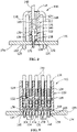
FIG. 1 is a perspective view of an illustrative connector housing with contact terminals of the present invention mated to a substrate. -
FIG. 2 is a perspective view of the connector housing with contact terminals ofFIG. 1 removed from the substrate. -
FIG. 3 is a cross-sectional view taken along line 3-3 ofFIG. 1 , showing the contact terminals in a fully mated position. -
FIG. 4 is a cross-sectional view taken along line 4-4 ofFIG. 1 , showing a respective contact terminal in a fully mated position. -
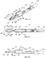
FIG. 5 is a perspective view of a contact terminal shown inFIG. 1 . -
FIG. 6 is a top view of the contact terminal ofFIG. 5 . -
FIG. 7 is a side view of the contact terminal ofFIG. 5 . -
FIG. 8 is a cross-sectional view of a second illustrative connector housing with second illustrative contact terminals, the second contact terminals are shown in a fully mated position. -
FIG. 9 is another cross-sectional view of the second illustrative connector housing with second illustrative contact terminals, the second contact terminals are shown in a fully mated position. -
FIG. 10 is a perspective view of the contact terminal shown inFIG. 8 . -
FIG. 11 is a top view of the contact terminal ofFIG. 10 . -
FIG. 12 is a side view of the contact terminal ofFIG. 10 . -
FIG. 13 is a perspective view of a contact terminal which is similar to that shown inFIG. 10 , with a resilient locking arm provided thereon. -
FIG. 14 is a perspective view of another illustrative contact terminal. -
FIG. 15 is a top view of the contact terminal ofFIG. 14 . -
FIG. 16 is a side view of the contact terminal ofFIG. 14 . -
FIG. 17 is a perspective view of a contact terminal which is similar to that shown inFIG. 14 , with a resilient locking arm provided thereon. -
FIG. 18 is a perspective view of a fourth illustrative contact terminal. -
FIG. 19 is a top view of the contact terminal ofFIG. 18 . -
FIG. 20 is a side view of the contact terminal ofFIG. 18 . -
FIG. 21 is a perspective view of a contact terminal which is similar to that shown inFIG. 18 , with a resilient locking arm provided thereon. - The description of illustrative embodiments according to principles of the present invention is intended to be read in connection with the accompanying drawings, which are to be considered part of the entire written description. In the description of embodiments of the invention disclosed herein, any reference to direction or orientation is merely intended for convenience of description and is not intended in any way to limit the scope of the present invention. Relative terms such as "lower," "upper," "horizontal," "vertical," "above," "below," "up," "down," "top" and "bottom" as well as derivative thereof (e.g., "horizontally," "downwardly," "upwardly," etc.) should be construed to refer to the orientation as then described or as shown in the drawing under discussion. These relative terms are for convenience of description only and do not require that the apparatus be constructed or operated in a particular orientation unless explicitly indicated as such. Terms such as "attached," "affixed," "connected," "coupled," "interconnected," and similar refer to a relationship wherein structures are secured or attached to one another either directly or indirectly through intervening structures, as well as both movable or rigid attachments or relationships, unless expressly described otherwise. Moreover, the features and benefits of the invention are illustrated by reference to the preferred embodiments. Accordingly, the invention expressly should not be limited to such preferred embodiments illustrating some possible non-limiting combination of features that may exist alone or in other combinations of features, the scope of the invention being defined by the claims appended hereto.
- Illustrative embodiments of the present invention are now described with reference to the Figures. Reference numerals are used throughout the detailed description to refer to the various elements and structures. Although the following detailed description contains many specifics for the purposes of illustration, a person of ordinary skill in the art will appreciate that many variations and alterations to the following details are within the scope of the invention. Accordingly, the following embodiments of the invention are set forth without any loss of generality to, and without imposing limitations upon, the claimed invention.
- As shown in
FIGS. 1 through 4 , a first illustrative embodiment of aconnector 10 has ahousing 12 with awire receiving end 14 and asubstrate mating end 16. Latchingarms 18 extend from proximate thewire receiving end 14 to beyond thesubstrate mating end 16. Thelatch arms 18 have lead-insurfaces 20 proximate free ends thereof. Latchingshoulders 22 are provided proximate the lead-insurfaces 20. In the illustrative embodiment, three latchingarms 18 are provided, with two extending from one side of thehousing 12 and the third extending from the opposite side of thehousing 12. However, other numbers and configurations of latchingarms 18 may be used. In addition, the latching arms may be provided on an additional part which is mated with the housing. - The
housing 12 hasterminal receiving cavities 24 extending from thewire receiving end 14 to thesubstrate mating end 16. As shown inFIG. 4 , lockingprojections 26 are provided in the terminal receivingcavities 24. The lockingprojections 26 are spaced from both thewire receiving end 14 and thesubstrate mating end 16. The lockingprojections 26 have lead-insurfaces 28 which face toward thewire receiving end 14 and lockingshoulders 30 which face toward thesubstrate mating end 16. -
Contact terminals 32 are positioned in the terminal receivingcavities 24. As shown inFIGS. 5 through 7 , thecontact terminals 32 haveconductor mating portions 34, securingportions 36 andsubstrate mating portions 38. Theconductor mating portions 34 are configured to terminateconductors 40 therein. Theconductors 40 may be terminated by crimping, insulation displacement, soldering or using other known methods of termination. - The securing
portions 36 have resilient lockingarms 42. Theresilient locking arms 42 extend from securingportions 36 whereby locking surfaces 44 are provided at free ends of the lockingarms 42. The lockingarms 42 and the locking surfaces 44 cooperate with the lockingprojections 26 and the locking shoulders 30 to retain theterminals 32 in position in the terminal receivingcavities 24, as shown inFIG. 4 . - The securing
portions 36 and thesubstrate mating portions 38 are formed by first planar sections or pieces ofconductive material 46 which are folded over atedges 48 to place folded over or second planar sections or piece/pieces ofconductive material 50 on top of the first planar piece/pieces ofconductive material 46. This effectively doubles the thickness of the conductive material at thesubstrate mating portions 38. - The first planar pieces of
conductive material 46 extend from the securingportions 36 to free ends 52.Curved portions 54 are provided proximate the free ends 52. The second planar pieces ofconductive material 50 extend from the securingportions 36 to free ends 56.Curved portions 58 are provided proximate the free ends 56. With the exceptions of thecurved portions planar pieces 46 and the secondplanar pieces 50 are provided in line, with the secondplanar pieces 50 being positioned on top of the firstplanar pieces 46 in the illustrative orientation shown inFIGS. 5 through 7 . - The
curved portions 54 are curved such that edges 60 of thecurved portions 54 extend away from thelongitudinal axes 62 of thesubstrate mating portions 38. Thecurved portions 58 are curved such that edges 64 of thecurved portions 58 extend away from thelongitudinal axes 62 of thesubstrate mating portions 38. Thecurved portions 58 extend in a direction from thelongitudinal axes 62 in the opposite direction as thecurved portions 54. - In use, the
connector 10 is moved into engagement with asubstrate 70, such as, but not limited to a panel or a printed circuit board, as shown inFIG. 1 . In the fully inserted position, the ends of the latchingarms 18 are positioned inlatch receiving openings 72 in thesubstrate 70. When fully inserted, the latchingshoulders 22 are engage, and are biased against, asurface 74 of thesubstrate 70 to removably retain theconnector 10 in position on thesubstrate 70. Alternatively, thelatch arms 18 may have an interference fit with thelatch receiving openings 72 or an additional component may be provided to ensure that theconnector 10 is positively positioned and prevented from movement relative to thesubstrate 70. - As the
connector 10 is moved from the position shown inFIG. 2 to the position shown inFIG. 1 , thesubstrate mating portions 38 are moved into plated throughholes 76 in thesubstrate 70. As insertion continues, thecurved portions holes 76, causing thecurved portions planar pieces curved portions 54 are on the firstplanar pieces 46 and thecurved portions 58 are on the secondplanar pieces 50, the movement of thecurved portions 54 is independent of the movement of thecurved portions 58. This allows the movement of thecurved portions terminals 32 and theconnector 10 to be inserted onto thesubstrate 70 with low insertion force. The low insertion force allows theconnector 10 to be inserted onto the substrate by a user or operator without the need for additional tooling. - Once inserted and positioned in the through
holes 70, as shown inFIG. 1 , theedges curved portions holes 76 and exert normal forces on the walls of the throughholes 76, as the first and the secondplanar pieces planar pieces terminals 32 with low normal forces allows theterminals 32,connector 10 and the throughholes 76 to be used over many cycles. For example, by adding a detent to the firstplanar piece 46 and/or the secondplanar piece 50, the firstplanar piece 46 and the secondplanar piece 50 may be locked together, thereby adjusting the normal force exerted by theterminals 32 on the walls of the through holes 70. This also can help prevent deflection stress or strain transition from being transferred to the securingportions 36. - As shown in
FIGS. 8 and 9 , a second illustrative embodiment of aconnector 110 has ahousing 112 with awire receiving end 114 and asubstrate mating end 116. Latchingarms 118 extend from proximate thewire receiving end 114 to beyond thesubstrate mating end 116. Thelatch arms 118 have lead-insurfaces 120 proximate free ends thereof. Latchingshoulders 122 are provided proximate the lead-insurfaces 120. - The
housing 112 has terminal receivingcavities 124 extend from thewire receiving end 114 to thesubstrate mating end 116. As shown inFIG. 8 , lockingprojections 126 are provided in the terminal receivingcavities 124. The lockingprojections 126 are spaced from both thewire receiving end 114 and thesubstrate mating end 116. The lockingprojections 126 have lead-insurfaces 128 which face toward thewire receiving end 114 and lockingshoulders 130 which face toward thesubstrate mating end 116. -
Contact terminals 132 are positioned in the terminal receivingcavities 124. As shown inFIGS. 10 through 12 , thecontact terminals 132 haveconductor mating portions 134, securingportions 136 andsubstrate mating portions 138. Theconductor mating portions 134 are configured to terminateconductors 140 therein. Theconductors 140 may be terminated by crimping, insulation displacement, soldering or using other known methods of termination. - The securing
portions 136 have lockingwalls 143. The lockingwalls 143 have locking surfaces 144. The lockingwalls 143 and the locking surfaces 144 cooperate with the lockingprojections 126 and the lockingshoulders 130 to retain theterminals 132 in position in the terminal receivingcavities 124, as shown inFIG. 8 . The securingportions 136 are formed by folding planar conductive material into box shaped members withtop walls 142, oppositely facingbottom walls 141, first side or lockingwalls 143 andsecond side walls 145. - The
substrate mating portions 138 have first resilient sections orarms 146 which extend from thefirst side walls 143 and second resilient sections orarms 150 which extend from thesecond side walls 145. - The first
resilient arms 146 extend from the securingportions 136 to free ends 152. The firstresilient arms 146 are formed to havecurved portions 154 provided proximate the free ends 152. The secondresilient arms 150 extend from the securingportions 136 to free ends 156. The secondresilient arms 150 are formed to havecurved portions 158 provided proximate the free ends 156. - The
curved portions 154 are curved such that faces 160 of thecurved portions 154 extend away from thelongitudinal axes 162 of thesubstrate mating portions 138. Thecurved portions 158 are curved such that faces 164 of thecurved portions 158 extend away from thelongitudinal axes 162 of thesubstrate mating portions 138. Thecurved portions 158 extend in a direction from thelongitudinal axes 162 in the opposite direction as thecurved portions 154. Projections ordimples 163 are provide on thefaces curved portions - In use, the
connector 110 is moved into engagement with asubstrate 170, such as, but not limited to a panel or a printed circuit board. In the fully inserted position, the ends of the latchingarms 118 are positioned in latch receiving openings (not shown) in thesubstrate 70. When fully inserted, the latchingshoulders 122 are positioned below or engage asurface 174 of thesubstrate 170 to removably retain theconnector 110 in position on thesubstrate 170. Alternatively, thelatch arms 118 may have an interference fit with the latch receiving openings 172 or an additional component may be provided to ensure that theconnector 110 is positively positioned and prevented from movement relative to thesubstrate 170. - As the
connector 110 is inserted onto thesubstrate 170, thesubstrate mating portions 138 are moved into plated throughholes 176 in thesubstrate 170. As insertion continues, thecurved portions holes 176, causing thecurved portions resilient arms curved portions 154 are on firstresilient arms 146 and thecurved portions 158 are on the secondresilient arms 150, the movement of thecurved portions 154 is independent of the movement of thecurved portions 158. This allows the movement of thecurved portions terminals 132 and theconnector 110 to be inserted onto thesubstrate 170 with low insertion force. The low insertion force allows theconnector 110 to be inserted onto the substrate by a user or operator without the need for additional tooling. - Once inserted and position in the through
holes 170, as shown inFIG. 9 , theprojections 163 of thecurved portions holes 176 and exert normal forces on the walls of the throughholes 176, as the first and the secondresilient arms resilient arms terminals 132 with low normal forces allows theterminals 132,connector 110 and the throughholes 176 to be used over many cycles. -
FIG. 13 illustrates contact terminals which is similar to contactterminals 132. However, in this embodiment thecontact securing portions 136 have resilient lockingarms 137. The resilient lockingarms 137 extend from securingportions 136 whereby lockingsurfaces 139 are provided at free ends of the lockingarms 137. The lockingarms 137 and the locking surfaces 139 cooperate with the lockingprojections 126 and the lockingshoulders 130 to retain theterminals 132 in position in the terminal receivingcavities 124. - A third illustrative embodiment of
contact terminals 232 is shown inFIGS. 14 through 16 . Thecontact terminals 232 haveconductor mating portions 234, securingportions 236 andsubstrate mating portions 238. Theconductor mating portions 234 are configured to terminate conductors 240 therein. The conductors 240 may be terminated by crimping, insulation displacement, soldering or using other known methods of termination. - The securing
portions 236 have lockingwalls 243. The lockingwalls 243 have locking surfaces 244. The securingportions 236 are formed by folding planar conductive material into box shaped members withtop walls 242, oppositely facingbottom walls 241, first side or lockingwalls 243 andsecond side walls 245. - The
substrate mating portions 238 havefirst arms 246 which extend from thetop walls 242 andsecond arms 250 which extend from thebottom walls 241. Thefirst arms 246 extend from the securingportions 236 to free ends 252.Thefirst arms 246 have a fork like configuration with firstresilient arms 247 and secondresilient arms 249. The firstresilient arms 247 are formed to havecurved portions 254 provided proximate the free ends 252. The secondresilient arms 249 are formed to havecurved portions 258 provided proximate the free ends 252. - The
second arms 250 extend from the securingportions 236 to free ends 256.Thefirst arms 250 have a fork like configuration with firstresilient arms 251 and secondresilient arms 253. The firstresilient arms 251 are formed to havecurved portions 255 provided proximate the free ends 256. The secondresilient arms 253 are formed to havecurved portions 259 provided proximate the free ends 256. Thefirst arms 246 and thesecond arms 250 are provided in line, with thefirst arms 246 being positioned on top of thesecond arms 250 in the illustrative orientation shown inFIGS. 13 through 15 . - The
curved portions curved portions longitudinal axes 262 of thesubstrate mating portions 238. Thecurved portions curved portions longitudinal axes 262 of thesubstrate mating portions 238. Thecurved portions longitudinal axes 262 in the opposite direction as thecurved portions - In use, as the
terminals 232 are moved into through holes of a substrate (not shown) thecurved portions curved portions resilient arms curved portions resilient arms curved portions curved portions terminals 232 to be inserted onto the substrate with low insertion force. The low insertion force allows theterminals 232 to be inserted onto the substrate by a user or operator without the need for additional tooling. - Once inserted and positioned in the through holes of the substrate, the
edges curved portions resilient arms resilient arms terminals 232 with low normal forces allows theterminals 232 to be used over many cycles. -
FIG. 17 illustrates contact terminals which is similar to contactterminals 232. However, in this embodiment thecontact securing portions 236 have resilient lockingarms 237. The resilient lockingarms 237 extend from securingportions 236 whereby lockingsurfaces 239 are provided at free ends of the lockingarms 237. The lockingarms 237 and the locking surfaces 239 cooperate with the locking projections and the locking shoulders to retain theterminals 232 in position in the terminal receiving cavities. - A fourth illustrative embodiment of
contact terminals 332 is shown inFIGS. 18 through 20 . Thecontact terminals 332 haveconductor mating portions 334, securingportions 336 andsubstrate mating portions 338. Theconductor mating portions 334 are configured to terminateconductors 340 therein. Theconductors 340 may be terminated by crimping, insulation displacement, soldering or using other known methods of termination. - The securing
portions 336 have lockingwalls 343. The lockingwalls 343 have locking surfaces 344. The lockingwalls 343 and the locking surfaces 344. The securingportions 336 are formed by folding planar conductive material into box shaped members withtop walls 342, oppositely facingbottom walls 341, first side or lockingwalls 343 andsecond side walls 345. - The
substrate mating portions 338 have firstresilient arms 346 which extend from thefirst side walls 343 and secondresilient arms 350 which extend from thesecond side walls 345. The firstresilient arms 346 have firstplanar portions 353,u-shaped portions 352 andcurved portions 354. Thecurved portions 354 extend from theu-shaped portions 352 back toward the securingportions 336. The secondresilient arms 350 have secondplanar portions 357,u-shaped portions 356 andcurved portions 358. Thecurved portions 358 extend from theu-shaped portions 356 back toward the securingportions 336. - The
curved portions 354 are curved such that faces 360 of thecurved portions 354 extend away from thelongitudinal axes 362 of thesubstrate mating portions 338. Thecurved portions 358 are curved such that faces 364 of thecurved portions 358 extend away from thelongitudinal axes 362 of thesubstrate mating portions 338. Thecurved portions 358 extend in a direction from thelongitudinal axes 362 in the opposite direction as thecurved portions 354. Projections ordimples 363 are provide on thefaces curved portions - In use, as the
terminals 332 are moved into through holes of a substrate (not shown) thecurved portions curved portions curved portions resilient arms curved portions 354 is independent of thecurved portions 358. This allows the movement of thecurved portions terminals 332 to be inserted onto the substrate with low insertion force. The low insertion force allows theterminals 332 to be inserted onto the substrate by a user or operator without the need for additional tooling. - Once inserted and position in the through holes of the substrate, the
projections 363 of thecurved portions curved portions curved portions terminals 332 with low normal forces allows theterminals 332 to be used over many cycles. -
FIG. 21 illustrates contact terminals which are similar to contactterminals 332. However, in this embodiment thecontact securing portions 336 have resilient lockingarms 337. The resilient lockingarms 337 extend from securingportions 336 whereby lockingsurfaces 339 are provided at free ends of the lockingarms 337. The lockingarms 337 and the locking surfaces 339 cooperate with the locking projections and the locking shoulders to retain theterminals 332 in position in the terminal receiving cavities. - While the invention has been described with reference to a preferred embodiment, it will be understood by those skilled in the art that various changes may be made and equivalents may be substituted for elements thereof without departing from the scope of the invention as defined in the accompanying claims. One skilled in the art will appreciate that the invention may be used with many modifications of structure, arrangement, proportions, sizes, materials and components and otherwise used in the practice of the invention, which are particularly adapted to specific environments and operative requirements without departing from the principles of the present invention. The presently disclosed embodiments are therefore to be considered in all respects as illustrative and not restrictive, the scope of the invention being defined by the appended claims, and not limited to the foregoing description or embodiments.
Claims (22)
- A low insertion force contact terminal (32) comprising:a conductor mating portion (34) for terminating a conductor (40) therein;a securing portion (36) for securing the terminal (32) in a terminal receiving cavity (24) of a housing (12);a substrate mating portion (38) extending from the securing portion (36), the substrate mating portion (38) having at least two sections which have curved portions (54, 58) thereon;wherein the at least two sections move independently, causing the curved portions (54, 58) to exert a normal force on walls of through holes (76) of a substrate (70) to which the contact terminal (32) is mated which is sufficient to provide a stable electrical connection while allowing for a low insertion force.
- The low insertion force contact terminal (32) as recited in claim 1, wherein a first section of the at least two sections of the substrate mating portion (38) is a first planar piece (46) of conductive material and a second section of the at least two sections is a second planar piece (50) of conductive material which is folded over at an edge (48) to place second planar pieces (50) of conductive material on top of the first planar pieces (46) of conductive material.
- The low insertion force contact terminal (32) as recited in claim 2, wherein with the exception of the curved portions (54, 58), the first planar pieces (46) and the second planar pieces (50) are provided in line, with the second planar pieces (50) being positioned on top of the first planar pieces (46).
- The low insertion force contact terminal (32) as recited in any preceding claim, wherein the curved portions (54, 58) are curved such that edges (60, 64) of the curved portions (54, 58) extend away from a longitudinal axis (62) of the substrate mating portion (38).
- The low insertion force contact terminal (32) as recited in claim 4, wherein a first curved portion (54) of the curved portions extends away from the longitudinal axis (62) and a second curved portion (58) of the curved portions extends away from the longitudinal axis (62) in an opposite direction to the first curved portion (54).
- The low insertion force contact terminal (32) as recited in any preceding claim, wherein the securing portion (36) has a resilient locking arm (42) with a locking surface (44) provided at a free end of the locking arm (42).
- The low insertion force contact terminal (32) as recited in claim 2 or any claim depending thereon, wherein a detent is provided on the first planar piece (46) or the second planar piece (50), wherein the first planar piece (46) and the second planar piece (50) are locked together to create a larger normal force and prevent deflection stress or stain transition from being transferred from the substrate mating portion (38) to the securing portion (36).
- The low insertion force contact terminal (132) as recited in claim 1 or any claim depending thereon, wherein the securing portion (136) is formed by folding planar conductive material into a box shaped member with a top wall (142), an oppositely facing bottom wall (141), a first side wall (143) and a second side wall (145), a first section of the at least two sections of the substrate mating portion (138) is a first resilient arm (146) which extends from the first side wall (143) and a second section of the at least two sections of the substrate mating portion (138) is a second resilient arm (150) which extends from the second side wall (145).
- The low insertion force contact terminal (132) as recited in claim 8, wherein the first resilient arm (146) has a first curved portion (154) of the curved portions with a first face (160) which extends away from a longitudinal axis (162) of the substrate mating portion (138).
- The low insertion force contact terminal (132) as recited in claim 9, wherein the second resilient arm (150) has a second curved portion (158) of the curved portions with a second face (164) which extends away from the longitudinal axis (162) of the substrate mating portion (138) in an opposite direction to the first curved portion (154).
- The low insertion force contact terminal (132) as recited in claim 10, wherein the first curved portion (154) and the second curved portion (158) have projections (163) provided on the faces (160, 164) thereof.
- The low insertion force contact terminal (132) as recited in any of claims 8, 9 and 10, wherein the securing portion (136) has a resilient locking arm (137) with a locking surface (139) provided at a free end of the locking arm (137).
- The low insertion force contact terminal (232) as recited in claim 8 or any claim depending thereon, wherein a first section of the at least two sections of the substrate mating portion (238) is a first arm (246) which extends from the top wall (242) and a second section of the at least two sections of the substrate mating portion (238) is a second arm (250) which extends from the bottom wall (241).
- The low insertion force contact terminal (232) as recited in claim 13, wherein the first arm (246) has a fork like configuration with a first resilient arm (247) and a second resilient arm (249), the first resilient arm (247) has a first curved portion (254) of the curved portion provided proximate a free end of the first resilient arm (247) and the second resilient arm (249) has a second curved portion (258) provided proximate a free end (252) of the second resilient arm (249).
- The low insertion force contact terminal (232) as recited in claim 14, wherein the second arm (250) has a fork like configuration with a third resilient arm (251) and a fourth resilient arm (253), the third resilient arm (251) has a third curved portion (255) of the curved portion provided proximate a free end of the third resilient arm (251) and the fourth resilient arm (253) has a fourth curved portion (259) provided proximate a free end (256) of the fourth resilient arm (253).
- The low insertion force contact terminal (232) as recited in any of claims 13, 14 and 15, wherein the first arm (246) and the second arm (250) are provided in line, with the first arm (246) being positioned on top of the second arm (250).
- The low insertion force contact terminal (232) as recited in any of claims 13 to 16, wherein the curved portions (254, 255, 258, 259) are curved such that edges of the curved portions extend away from a longitudinal axis (262) of the substrate mating portions (238).
- The low insertion force contact terminal (232) as recited in claims 14, 15 and 17, wherein the first curved portion (254) and the third curve portion (255) extend away from the longitudinal axis (262) and the second curved portion (258) and the fourth curve portion (259) extend in a direction from the longitudinal axis (262) in the opposite direction to the first curved portion (254) and the third curve portion (255).
- The low insertion force contact terminal (332) as recited in claim 8, wherein the first resilient arm (346) has a first planar portion (353), a first u-shaped portion (352) and a first curved portion (354), the first curved portion (354) extends from the first u-shaped portion (352) back towards the securing portion (336), the second resilient arm (350) has a second planar portion (357), a second u-shaped portion (356) and a second curved portion (358), the second curved portion (358) extends from the second u-shaped portion (356) back towards the securing portion (336).
- The low insertion force contact terminal (332) as recited in claim 19, wherein a face (360) of the first curved portion (354) extends away from a longitudinal axis (362) of the substrate mating portion (338) and a face (364) of the second curved portion (358) extends away from the longitudinal axis (362) in the opposite direction to the first curved portions (354).
- The low insertion force contact terminal (32) as recited in any preceding claim, wherein the insertion or normal force is equal to or less than 5 Newtons.
- The low insertion force contact terminal (32) as recited in any preceding claim, wherein the contact terminal (32) is positioned in a housing (12) of a connector, the connector (10) having one or more connector latching arms (18) which cooperate with openings (72) in a substrate (70) to properly position and lock the connector (10) to the substrate (70).
Applications Claiming Priority (1)
| Application Number | Priority Date | Filing Date | Title |
|---|---|---|---|
| IN202111023638 | 2021-05-27 |
Publications (2)
| Publication Number | Publication Date |
|---|---|
| EP4096024A1 true EP4096024A1 (en) | 2022-11-30 |
| EP4096024B1 EP4096024B1 (en) | 2025-03-26 |
Family
ID=81851345
Family Applications (1)
| Application Number | Title | Priority Date | Filing Date |
|---|---|---|---|
| EP22175952.5A Active EP4096024B1 (en) | 2021-05-27 | 2022-05-27 | Low insertion force contact terminal |
Country Status (2)
| Country | Link |
|---|---|
| US (2) | US11715902B2 (en) |
| EP (1) | EP4096024B1 (en) |
Cited By (2)
| Publication number | Priority date | Publication date | Assignee | Title |
|---|---|---|---|---|
| CN119108837A (en) * | 2024-11-05 | 2024-12-10 | 浙江珠城科技股份有限公司 | Multi-support fatigue-resistant terminal connector |
| EP4586410A1 (en) * | 2024-01-12 | 2025-07-16 | Honeywell International Inc. | Electrical terminal for an electronic device |
Families Citing this family (2)
| Publication number | Priority date | Publication date | Assignee | Title |
|---|---|---|---|---|
| US11804667B2 (en) * | 2021-07-22 | 2023-10-31 | Te Connectivity Solutions Gmbh | Board-to-board connector assembly for add-in cards |
| TWI867996B (en) * | 2024-04-12 | 2024-12-21 | 禾昌興業股份有限公司 | Mid mount easy-lock connector |
Citations (4)
| Publication number | Priority date | Publication date | Assignee | Title |
|---|---|---|---|---|
| US3963316A (en) * | 1972-10-19 | 1976-06-15 | Amp Incorporated | Electrical connector for a printed circuit board |
| US5209680A (en) * | 1992-01-10 | 1993-05-11 | Molex Incorporated | Male electrical terminal with anti-overstress means |
| US9368886B2 (en) * | 2009-09-21 | 2016-06-14 | Würth Elektronik Ics Gmbh & Co. Kg | Multi-fork press-in pin |
| CA3107090A1 (en) * | 2019-07-10 | 2021-01-14 | Wurth Elektronik Eisos Gmbh & Co. Kg | Direct plug-in connector |
Family Cites Families (19)
| Publication number | Priority date | Publication date | Assignee | Title |
|---|---|---|---|---|
| US3654592A (en) * | 1970-09-21 | 1972-04-04 | Berg Electronics Inc | Electrical connector and block |
| GB8908411D0 (en) * | 1989-04-13 | 1989-06-01 | Amp Holland | Surface mount electrical connector |
| US5374204A (en) * | 1993-11-30 | 1994-12-20 | The Whitake Corporation | Electrical terminal with compliant pin section |
| US6036545A (en) * | 1996-11-27 | 2000-03-14 | The Whitaker Corporation | Decoupled BNC connector |
| US5876241A (en) * | 1997-04-15 | 1999-03-02 | The Whitaker Corporation | Horizontal battery connector |
| US6250944B1 (en) * | 2000-06-26 | 2001-06-26 | Hon Hai Precision Ind. Co., Ltd. | Latch device for releasably locking mating electrical connectors together |
| US6319021B1 (en) * | 2000-12-19 | 2001-11-20 | Hon Hai Precision Ind. Co., Ltd. | Power connector providing improved performance |
| US6821135B1 (en) * | 2003-08-06 | 2004-11-23 | Tyco Electronics Corporation | Alignment plate for aligning connector terminals |
| US7377823B2 (en) * | 2005-05-23 | 2008-05-27 | J.S.T. Corporation | Press-fit pin |
| PL2899812T3 (en) * | 2008-12-03 | 2023-01-30 | Würth Elektronik Ics Gmbh & Co. Kg | Connection arrangement on circuit boards |
| JP5053338B2 (en) * | 2009-07-23 | 2012-10-17 | 京セラコネクタプロダクツ株式会社 | Contacts and connectors |
| US20120116860A1 (en) * | 2010-11-04 | 2012-05-10 | Microsoft Corporation | Payment determination in auctions |
| DE102011005073A1 (en) * | 2011-03-03 | 2012-09-06 | Würth Elektronik Ics Gmbh & Co. Kg | Tandem Multi Fork press-in pin |
| JP2013037791A (en) * | 2011-08-04 | 2013-02-21 | Sumitomo Wiring Syst Ltd | Connection structure of circuit board and terminal fitting |
| US9525852B2 (en) * | 2013-08-02 | 2016-12-20 | General Electric Company | Systems and methods for embedded imaging clocking |
| DE102013218441A1 (en) * | 2013-09-13 | 2015-04-02 | Würth Elektronik Ics Gmbh & Co. Kg | Direct plug-in device with Vorjustiereinrichtung and relative to this sliding locking device |
| JP5839099B1 (en) * | 2014-12-03 | 2016-01-06 | 第一精工株式会社 | Connector terminal for press-fit |
| US10153597B1 (en) * | 2017-09-18 | 2018-12-11 | David Polinski | PC board mounted jack connector assembly |
| JP7482021B2 (en) * | 2020-12-25 | 2024-05-13 | 日本航空電子工業株式会社 | Electrical component |
-
2021
- 2021-07-22 US US17/382,842 patent/US11715902B2/en active Active
-
2022
- 2022-05-27 EP EP22175952.5A patent/EP4096024B1/en active Active
-
2023
- 2023-06-16 US US18/336,091 patent/US12476407B2/en active Active
Patent Citations (4)
| Publication number | Priority date | Publication date | Assignee | Title |
|---|---|---|---|---|
| US3963316A (en) * | 1972-10-19 | 1976-06-15 | Amp Incorporated | Electrical connector for a printed circuit board |
| US5209680A (en) * | 1992-01-10 | 1993-05-11 | Molex Incorporated | Male electrical terminal with anti-overstress means |
| US9368886B2 (en) * | 2009-09-21 | 2016-06-14 | Würth Elektronik Ics Gmbh & Co. Kg | Multi-fork press-in pin |
| CA3107090A1 (en) * | 2019-07-10 | 2021-01-14 | Wurth Elektronik Eisos Gmbh & Co. Kg | Direct plug-in connector |
Cited By (2)
| Publication number | Priority date | Publication date | Assignee | Title |
|---|---|---|---|---|
| EP4586410A1 (en) * | 2024-01-12 | 2025-07-16 | Honeywell International Inc. | Electrical terminal for an electronic device |
| CN119108837A (en) * | 2024-11-05 | 2024-12-10 | 浙江珠城科技股份有限公司 | Multi-support fatigue-resistant terminal connector |
Also Published As
| Publication number | Publication date |
|---|---|
| US12476407B2 (en) | 2025-11-18 |
| EP4096024B1 (en) | 2025-03-26 |
| US20220384980A1 (en) | 2022-12-01 |
| US11715902B2 (en) | 2023-08-01 |
| US20230327359A1 (en) | 2023-10-12 |
Similar Documents
| Publication | Publication Date | Title |
|---|---|---|
| US11715902B2 (en) | Low insertion force contact terminal | |
| KR101013825B1 (en) | Stacking connector | |
| US5201663A (en) | Connector with flexible mounting features | |
| US7255584B2 (en) | Electrical connector for a flat-type cable | |
| KR20020048873A (en) | Electric connector | |
| US12021330B2 (en) | Connector with a mating assistance assembly | |
| JP5392929B2 (en) | connector | |
| JP2002530822A (en) | Mating electrical connector assembly having guide member and removal recess | |
| KR20100031471A (en) | Blade and receptacle power connector | |
| US12489251B2 (en) | Plug, connector, and receptacle | |
| CN112997362B (en) | Electrical connector and harness assembly with compression contacts | |
| CN110534969A (en) | Electrical connector and connector combination with the electrical connector | |
| CN212323275U (en) | floating connector | |
| JP5168393B2 (en) | Board terminal and board connector | |
| JP7283971B2 (en) | BOARD CONNECTOR AND BOARD CONNECTOR STRUCTURE | |
| JP3620833B2 (en) | Module connector | |
| US8011958B1 (en) | E-easy series connector assembly with shielding function | |
| CN115117664B (en) | Connector terminal element with double locks and double clamps, connector and connecting method thereof | |
| CN110858686A (en) | contact assembly | |
| CN117134141A (en) | Low insertion force contact terminal | |
| US20230411879A1 (en) | Printed circuit board connector having hermaphroditic contact elements | |
| JP5737446B1 (en) | Electrical connector mating structure | |
| JP4602050B2 (en) | Multi-connection type header connector and vertical socket connector and horizontal socket connector connected to this | |
| CN100502152C (en) | Connector | |
| US20260024930A1 (en) | Plug connector and set having a plug connector and a solder anchor |
Legal Events
| Date | Code | Title | Description |
|---|---|---|---|
| PUAI | Public reference made under article 153(3) epc to a published international application that has entered the european phase |
Free format text: ORIGINAL CODE: 0009012 |
|
| STAA | Information on the status of an ep patent application or granted ep patent |
Free format text: STATUS: THE APPLICATION HAS BEEN PUBLISHED |
|
| AK | Designated contracting states |
Kind code of ref document: A1 Designated state(s): AL AT BE BG CH CY CZ DE DK EE ES FI FR GB GR HR HU IE IS IT LI LT LU LV MC MK MT NL NO PL PT RO RS SE SI SK SM TR |
|
| STAA | Information on the status of an ep patent application or granted ep patent |
Free format text: STATUS: REQUEST FOR EXAMINATION WAS MADE |
|
| 17P | Request for examination filed |
Effective date: 20230517 |
|
| RBV | Designated contracting states (corrected) |
Designated state(s): AL AT BE BG CH CY CZ DE DK EE ES FI FR GB GR HR HU IE IS IT LI LT LU LV MC MK MT NL NO PL PT RO RS SE SI SK SM TR |
|
| GRAP | Despatch of communication of intention to grant a patent |
Free format text: ORIGINAL CODE: EPIDOSNIGR1 |
|
| STAA | Information on the status of an ep patent application or granted ep patent |
Free format text: STATUS: GRANT OF PATENT IS INTENDED |
|
| INTG | Intention to grant announced |
Effective date: 20241022 |
|
| GRAS | Grant fee paid |
Free format text: ORIGINAL CODE: EPIDOSNIGR3 |
|
| GRAA | (expected) grant |
Free format text: ORIGINAL CODE: 0009210 |
|
| STAA | Information on the status of an ep patent application or granted ep patent |
Free format text: STATUS: THE PATENT HAS BEEN GRANTED |
|
| AK | Designated contracting states |
Kind code of ref document: B1 Designated state(s): AL AT BE BG CH CY CZ DE DK EE ES FI FR GB GR HR HU IE IS IT LI LT LU LV MC MK MT NL NO PL PT RO RS SE SI SK SM TR |
|
| REG | Reference to a national code |
Ref country code: GB Ref legal event code: FG4D |
|
| REG | Reference to a national code |
Ref country code: CH Ref legal event code: EP |
|
| REG | Reference to a national code |
Ref country code: IE Ref legal event code: FG4D |
|
| REG | Reference to a national code |
Ref country code: DE Ref legal event code: R096 Ref document number: 602022012141 Country of ref document: DE |
|
| PG25 | Lapsed in a contracting state [announced via postgrant information from national office to epo] |
Ref country code: RS Free format text: LAPSE BECAUSE OF FAILURE TO SUBMIT A TRANSLATION OF THE DESCRIPTION OR TO PAY THE FEE WITHIN THE PRESCRIBED TIME-LIMIT Effective date: 20250626 |
|
| PG25 | Lapsed in a contracting state [announced via postgrant information from national office to epo] |
Ref country code: FI Free format text: LAPSE BECAUSE OF FAILURE TO SUBMIT A TRANSLATION OF THE DESCRIPTION OR TO PAY THE FEE WITHIN THE PRESCRIBED TIME-LIMIT Effective date: 20250326 |
|
| REG | Reference to a national code |
Ref country code: LT Ref legal event code: MG9D |
|
| PG25 | Lapsed in a contracting state [announced via postgrant information from national office to epo] |
Ref country code: NO Free format text: LAPSE BECAUSE OF FAILURE TO SUBMIT A TRANSLATION OF THE DESCRIPTION OR TO PAY THE FEE WITHIN THE PRESCRIBED TIME-LIMIT Effective date: 20250626 |
|
| PG25 | Lapsed in a contracting state [announced via postgrant information from national office to epo] |
Ref country code: HR Free format text: LAPSE BECAUSE OF FAILURE TO SUBMIT A TRANSLATION OF THE DESCRIPTION OR TO PAY THE FEE WITHIN THE PRESCRIBED TIME-LIMIT Effective date: 20250326 |
|
| PG25 | Lapsed in a contracting state [announced via postgrant information from national office to epo] |
Ref country code: LV Free format text: LAPSE BECAUSE OF FAILURE TO SUBMIT A TRANSLATION OF THE DESCRIPTION OR TO PAY THE FEE WITHIN THE PRESCRIBED TIME-LIMIT Effective date: 20250326 |
|
| PG25 | Lapsed in a contracting state [announced via postgrant information from national office to epo] |
Ref country code: GR Free format text: LAPSE BECAUSE OF FAILURE TO SUBMIT A TRANSLATION OF THE DESCRIPTION OR TO PAY THE FEE WITHIN THE PRESCRIBED TIME-LIMIT Effective date: 20250627 Ref country code: BG Free format text: LAPSE BECAUSE OF FAILURE TO SUBMIT A TRANSLATION OF THE DESCRIPTION OR TO PAY THE FEE WITHIN THE PRESCRIBED TIME-LIMIT Effective date: 20250326 |
|
| PGFP | Annual fee paid to national office [announced via postgrant information from national office to epo] |
Ref country code: AT Payment date: 20250721 Year of fee payment: 4 |
|
| REG | Reference to a national code |
Ref country code: NL Ref legal event code: MP Effective date: 20250326 |
|
| PG25 | Lapsed in a contracting state [announced via postgrant information from national office to epo] |
Ref country code: NL Free format text: LAPSE BECAUSE OF FAILURE TO SUBMIT A TRANSLATION OF THE DESCRIPTION OR TO PAY THE FEE WITHIN THE PRESCRIBED TIME-LIMIT Effective date: 20250326 |
|
| PG25 | Lapsed in a contracting state [announced via postgrant information from national office to epo] |
Ref country code: SE Free format text: LAPSE BECAUSE OF FAILURE TO SUBMIT A TRANSLATION OF THE DESCRIPTION OR TO PAY THE FEE WITHIN THE PRESCRIBED TIME-LIMIT Effective date: 20250326 |
|
| REG | Reference to a national code |
Ref country code: AT Ref legal event code: MK05 Ref document number: 1779907 Country of ref document: AT Kind code of ref document: T Effective date: 20250326 |
|
| PG25 | Lapsed in a contracting state [announced via postgrant information from national office to epo] |
Ref country code: SM Free format text: LAPSE BECAUSE OF FAILURE TO SUBMIT A TRANSLATION OF THE DESCRIPTION OR TO PAY THE FEE WITHIN THE PRESCRIBED TIME-LIMIT Effective date: 20250326 |
|
| PG25 | Lapsed in a contracting state [announced via postgrant information from national office to epo] |
Ref country code: ES Free format text: LAPSE BECAUSE OF FAILURE TO SUBMIT A TRANSLATION OF THE DESCRIPTION OR TO PAY THE FEE WITHIN THE PRESCRIBED TIME-LIMIT Effective date: 20250326 Ref country code: PT Free format text: LAPSE BECAUSE OF FAILURE TO SUBMIT A TRANSLATION OF THE DESCRIPTION OR TO PAY THE FEE WITHIN THE PRESCRIBED TIME-LIMIT Effective date: 20250728 |
|
| PG25 | Lapsed in a contracting state [announced via postgrant information from national office to epo] |
Ref country code: PL Free format text: LAPSE BECAUSE OF FAILURE TO SUBMIT A TRANSLATION OF THE DESCRIPTION OR TO PAY THE FEE WITHIN THE PRESCRIBED TIME-LIMIT Effective date: 20250326 Ref country code: IT Free format text: LAPSE BECAUSE OF FAILURE TO SUBMIT A TRANSLATION OF THE DESCRIPTION OR TO PAY THE FEE WITHIN THE PRESCRIBED TIME-LIMIT Effective date: 20250326 |
|
| PG25 | Lapsed in a contracting state [announced via postgrant information from national office to epo] |
Ref country code: AT Free format text: LAPSE BECAUSE OF FAILURE TO SUBMIT A TRANSLATION OF THE DESCRIPTION OR TO PAY THE FEE WITHIN THE PRESCRIBED TIME-LIMIT Effective date: 20250326 |
|
| PG25 | Lapsed in a contracting state [announced via postgrant information from national office to epo] |
Ref country code: EE Free format text: LAPSE BECAUSE OF FAILURE TO SUBMIT A TRANSLATION OF THE DESCRIPTION OR TO PAY THE FEE WITHIN THE PRESCRIBED TIME-LIMIT Effective date: 20250326 |
|
| PG25 | Lapsed in a contracting state [announced via postgrant information from national office to epo] |
Ref country code: RO Free format text: LAPSE BECAUSE OF FAILURE TO SUBMIT A TRANSLATION OF THE DESCRIPTION OR TO PAY THE FEE WITHIN THE PRESCRIBED TIME-LIMIT Effective date: 20250326 |
|
| PG25 | Lapsed in a contracting state [announced via postgrant information from national office to epo] |
Ref country code: SK Free format text: LAPSE BECAUSE OF FAILURE TO SUBMIT A TRANSLATION OF THE DESCRIPTION OR TO PAY THE FEE WITHIN THE PRESCRIBED TIME-LIMIT Effective date: 20250326 |
|
| PG25 | Lapsed in a contracting state [announced via postgrant information from national office to epo] |
Ref country code: IS Free format text: LAPSE BECAUSE OF FAILURE TO SUBMIT A TRANSLATION OF THE DESCRIPTION OR TO PAY THE FEE WITHIN THE PRESCRIBED TIME-LIMIT Effective date: 20250726 |
|
| REG | Reference to a national code |
Ref country code: CH Ref legal event code: H13 Free format text: ST27 STATUS EVENT CODE: U-0-0-H10-H13 (AS PROVIDED BY THE NATIONAL OFFICE) Effective date: 20251223 |
|
| REG | Reference to a national code |
Ref country code: DE Ref legal event code: R097 Ref document number: 602022012141 Country of ref document: DE |
|
| PG25 | Lapsed in a contracting state [announced via postgrant information from national office to epo] |
Ref country code: DK Free format text: LAPSE BECAUSE OF FAILURE TO SUBMIT A TRANSLATION OF THE DESCRIPTION OR TO PAY THE FEE WITHIN THE PRESCRIBED TIME-LIMIT Effective date: 20250326 |
|
| PG25 | Lapsed in a contracting state [announced via postgrant information from national office to epo] |
Ref country code: LU Free format text: LAPSE BECAUSE OF NON-PAYMENT OF DUE FEES Effective date: 20250527 |
|
| PG25 | Lapsed in a contracting state [announced via postgrant information from national office to epo] |
Ref country code: CH Free format text: LAPSE BECAUSE OF NON-PAYMENT OF DUE FEES Effective date: 20250531 |
|
| PG25 | Lapsed in a contracting state [announced via postgrant information from national office to epo] |
Ref country code: CZ Free format text: LAPSE BECAUSE OF FAILURE TO SUBMIT A TRANSLATION OF THE DESCRIPTION OR TO PAY THE FEE WITHIN THE PRESCRIBED TIME-LIMIT Effective date: 20250326 |
|
| REG | Reference to a national code |
Ref country code: BE Ref legal event code: MM Effective date: 20250531 |
|
| PG25 | Lapsed in a contracting state [announced via postgrant information from national office to epo] |
Ref country code: MC Free format text: LAPSE BECAUSE OF FAILURE TO SUBMIT A TRANSLATION OF THE DESCRIPTION OR TO PAY THE FEE WITHIN THE PRESCRIBED TIME-LIMIT Effective date: 20250326 |
|
| PLBE | No opposition filed within time limit |
Free format text: ORIGINAL CODE: 0009261 |
|
| STAA | Information on the status of an ep patent application or granted ep patent |
Free format text: STATUS: NO OPPOSITION FILED WITHIN TIME LIMIT |
|
| REG | Reference to a national code |
Ref country code: CH Ref legal event code: L10 Free format text: ST27 STATUS EVENT CODE: U-0-0-L10-L00 (AS PROVIDED BY THE NATIONAL OFFICE) Effective date: 20260211 |
|
| 26N | No opposition filed |
Effective date: 20260105 |
|
| PG25 | Lapsed in a contracting state [announced via postgrant information from national office to epo] |
Ref country code: IE Free format text: LAPSE BECAUSE OF NON-PAYMENT OF DUE FEES Effective date: 20250527 |
|
| PG25 | Lapsed in a contracting state [announced via postgrant information from national office to epo] |
Ref country code: BE Free format text: LAPSE BECAUSE OF NON-PAYMENT OF DUE FEES Effective date: 20250531 |
|
| PG25 | Lapsed in a contracting state [announced via postgrant information from national office to epo] |
Ref country code: LT Free format text: LAPSE BECAUSE OF FAILURE TO SUBMIT A TRANSLATION OF THE DESCRIPTION OR TO PAY THE FEE WITHIN THE PRESCRIBED TIME-LIMIT Effective date: 20250326 |
|
| PGFP | Annual fee paid to national office [announced via postgrant information from national office to epo] |
Ref country code: DE Payment date: 20260331 Year of fee payment: 5 |
|
| PGFP | Annual fee paid to national office [announced via postgrant information from national office to epo] |
Ref country code: FR Payment date: 20260401 Year of fee payment: 5 |
|
| PG25 | Lapsed in a contracting state [announced via postgrant information from national office to epo] |
Ref country code: CY Free format text: LAPSE BECAUSE OF FAILURE TO SUBMIT A TRANSLATION OF THE DESCRIPTION OR TO PAY THE FEE WITHIN THE PRESCRIBED TIME-LIMIT Effective date: 20250326 |