EP4095880A2 - Two-piece fuse endbell with pre-cast/pre-molded alignment slots and optional interface crush ribs - Google Patents
Two-piece fuse endbell with pre-cast/pre-molded alignment slots and optional interface crush ribs Download PDFInfo
- Publication number
- EP4095880A2 EP4095880A2 EP22170569.2A EP22170569A EP4095880A2 EP 4095880 A2 EP4095880 A2 EP 4095880A2 EP 22170569 A EP22170569 A EP 22170569A EP 4095880 A2 EP4095880 A2 EP 4095880A2
- Authority
- EP
- European Patent Office
- Prior art keywords
- endbell
- fuse
- assembly
- terminal assembly
- terminal
- Prior art date
- Legal status (The legal status is an assumption and is not a legal conclusion. Google has not performed a legal analysis and makes no representation as to the accuracy of the status listed.)
- Granted
Links
Images








Classifications
-
- H—ELECTRICITY
- H01—ELECTRIC ELEMENTS
- H01H—ELECTRIC SWITCHES; RELAYS; SELECTORS; EMERGENCY PROTECTIVE DEVICES
- H01H85/00—Protective devices in which the current flows through a part of fusible material and this current is interrupted by displacement of the fusible material when this current becomes excessive
- H01H85/02—Details
- H01H85/22—Intermediate or auxiliary parts for carrying, holding, or retaining fuse, co-operating with base or fixed holder, and removable therefrom for renewing the fuse
-
- H—ELECTRICITY
- H01—ELECTRIC ELEMENTS
- H01H—ELECTRIC SWITCHES; RELAYS; SELECTORS; EMERGENCY PROTECTIVE DEVICES
- H01H85/00—Protective devices in which the current flows through a part of fusible material and this current is interrupted by displacement of the fusible material when this current becomes excessive
- H01H85/02—Details
- H01H85/04—Fuses, i.e. expendable parts of the protective device, e.g. cartridges
- H01H85/05—Component parts thereof
- H01H85/143—Electrical contacts; Fastening fusible members to such contacts
-
- H—ELECTRICITY
- H01—ELECTRIC ELEMENTS
- H01H—ELECTRIC SWITCHES; RELAYS; SELECTORS; EMERGENCY PROTECTIVE DEVICES
- H01H69/00—Apparatus or processes for the manufacture of emergency protective devices
- H01H69/02—Manufacture of fuses
-
- H—ELECTRICITY
- H01—ELECTRIC ELEMENTS
- H01H—ELECTRIC SWITCHES; RELAYS; SELECTORS; EMERGENCY PROTECTIVE DEVICES
- H01H85/00—Protective devices in which the current flows through a part of fusible material and this current is interrupted by displacement of the fusible material when this current becomes excessive
- H01H85/0013—Means for preventing damage, e.g. by ambient influences to the fuse
- H01H85/0021—Means for preventing damage, e.g. by ambient influences to the fuse water or dustproof devices
- H01H85/003—Means for preventing damage, e.g. by ambient influences to the fuse water or dustproof devices casings for the fusible element
-
- H—ELECTRICITY
- H01—ELECTRIC ELEMENTS
- H01H—ELECTRIC SWITCHES; RELAYS; SELECTORS; EMERGENCY PROTECTIVE DEVICES
- H01H85/00—Protective devices in which the current flows through a part of fusible material and this current is interrupted by displacement of the fusible material when this current becomes excessive
- H01H85/0078—Security-related arrangements
-
- H—ELECTRICITY
- H01—ELECTRIC ELEMENTS
- H01H—ELECTRIC SWITCHES; RELAYS; SELECTORS; EMERGENCY PROTECTIVE DEVICES
- H01H85/00—Protective devices in which the current flows through a part of fusible material and this current is interrupted by displacement of the fusible material when this current becomes excessive
- H01H85/02—Details
- H01H85/04—Fuses, i.e. expendable parts of the protective device, e.g. cartridges
- H01H85/05—Component parts thereof
- H01H85/165—Casings
-
- H—ELECTRICITY
- H01—ELECTRIC ELEMENTS
- H01H—ELECTRIC SWITCHES; RELAYS; SELECTORS; EMERGENCY PROTECTIVE DEVICES
- H01H85/00—Protective devices in which the current flows through a part of fusible material and this current is interrupted by displacement of the fusible material when this current becomes excessive
- H01H85/02—Details
- H01H85/04—Fuses, i.e. expendable parts of the protective device, e.g. cartridges
- H01H85/05—Component parts thereof
- H01H85/143—Electrical contacts; Fastening fusible members to such contacts
- H01H85/153—Knife-blade-end contacts
Definitions
- Each endbell portion 610 includes a feature surface 720, including a raised portion 718, a semi-circular surface 722 at a circumferential edge of the endbell portion, and two flat side surfaces 724a and 724b (collectively, "side surfaces 724").
- Side surface 724a shows an endbell aperture 732, which is a transverse cylindrical void visible on either side of the endbell portion 610.
- the endbell aperture 732 is used to fill the fuse assembly 500 with sand or other material once the two endbells are connected to the fuse body, after which the aperture is sealed with plugs on both sides ( FIGs. 5 and 6B ).
- the projection 916 of the endbell portion 910a will fit into the recess 912a, with the recess (not shown) of the endbell portion 912b fitting into the recess 912b.
Landscapes
- Engineering & Computer Science (AREA)
- Manufacturing & Machinery (AREA)
- Computer Security & Cryptography (AREA)
- Fuses (AREA)
- Injection Moulding Of Plastics Or The Like (AREA)
Abstract
Description
- Embodiments of the present disclosure relate to fuse assemblies, and, more particularly, to fuse assemblies having two-piece endbells.
- Used in electrical systems to protect against excessive current, fuses are sacrificial devices which break when an overcurrent condition occurs. Fuses include a fuse element, such as a metal wire or strip, that links two metal contact terminals together, and which melts/breaks if too much current flows. The breakage causes an open circuit, thus protecting devices to which the fuse is connected. Fuses come in a variety of shapes and sizes and have many applications, from small circuit electronics to large-scale industrial applications. In addition to being a component protection device, fuses are also safety devices, such as when used in vehicles, as they protect against fires in response to vehicle accidents.
- Some fuses may include endbells at either side of the fuse body, with a fuse element disposed in the fuse body. The endbells are designed to support and protect the fuse element from external forces and environmental stresses. The existing fuse technology utilizes two fully circular endbells, each of which is engaged such as by first press-fitting or brazing into its respective separate terminal before the fuse element is attached. This assembly method thus involves a secondary process, such as soldering or welding, to attach the fuse element between the two terminals, increasing the complexity of manufacture and risking quality deviation. Further, the sliding interface between conductive terminal and endbell during assembly is not designed to produce a sealed envelope between fuse contents and the environment.
- The endbells are secured to the fuse body using insertion pins. Drilling holes in the endbells, which are typically made of a softer metal than the metal used for the fuse terminal, can be messy, resulting in contaminants being left inside the fuse body. Tight sealing of the endbells to the fuse body ensures that the fuse assembly operates as designed. Thus, the endbells may be sealed to the fuse body using adhesive materials, which can also be messy.
- It is with respect to these and other considerations that the present improvements may be useful.
- This Summary is provided to introduce a selection of concepts in a simplified form that are further described below in the Detailed Description. This Summary is not intended to identify key or essential features of the claimed subject matter, nor is it intended as an aid in determining the scope of the claimed subject matter.
- An exemplary embodiment of a fuse assembly in accordance with the present disclosure may include a fuse body to house a fuse element, a terminal assembly, and an endbell. The terminal assembly has first and second opposing surfaces and features a fuse element extending between a first terminal and a second terminal. The endbell includes first and second endbell portions, each having a crush rib. When the two endbell portions are fastened to one another with the terminal assembly sandwiched between them, the first crush rib engages the first surface of the terminal assembly and the second crush rib engages the second surface of the terminal assembly such that the first crush rib and the second crush rib form a seal around the terminal assembly.
- An exemplary embodiment of an endbell in accordance with the present disclosure, along with a second endbell, is adapted to secure a terminal assembly inside a fuse housing and may include a first endbell portion and a second endbell portion. The first endbell portion has a first protrusion, a first receptacle, and a first crush rib. The first crush rib is adapted to engage with a first surface of a terminal assembly, which includes the fuse element. The second endbell portion has a second protrusion, a second receptacle, and a second crush rib. The second crush is adapted to engage with a second surface of the terminal assembly opposite a first surface. In response to the first endbell portion being fastened to the second endbell portion, the first protrusion engages the second receptacle and the second protrusion engages the first receptacle, forming a seal around the terminal assembly.
- Another exemplary embodiment of a fuse assembly in accordance with the present disclosure may include a fuse body, first and second endbell portions, and first and second insertion pins. The fuse body is molded with first and second holes. The first endbell portion is molded with a first slot formed radially into its circumferential edge, forming a radial cavity through the first endbell. The second endbell portion is molded with a second slot formed radially into its circumferential edge, forming a radial cavity through the second endbell. The first insertion pin extends through the first hole and the first slot and the second insertion pin extends through the second hole and the second slot, and the first and second insertion pins secure the first and second endbell portions to the fuse body.
-
-
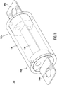
FIG. 1 is a diagram illustrating a fuse assembly, in accordance with exemplary embodiments; -
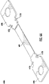
FIGs. 2A-2C are diagrams illustrating a terminal assembly for the fuse assembly ofFIG. 1 , in accordance with exemplary embodiments; -
FIGs. 3A and 3B are diagrams illustrating endbell portions for the fuse assembly ofFIG. 1 , in accordance with exemplary embodiments; -
FIGs. 4A and 4B are diagrams illustrating endbell portion coupling for the fuse assembly ofFIG. 1 , in accordance with exemplary embodiments; -
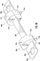
FIG. 5 is a diagram illustrating a fuse assembly, in accordance with exemplary embodiments; -
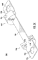
FIGs. 6A-6C are diagrams illustrating a terminal assembly for the fuse assembly ofFIG. 5 , in accordance with exemplary embodiments; -
FIGs. 7A and 7B are diagrams illustrating endbell portion and endbell portion coupling of the fuse assembly ofFIG. 5 , in accordance with exemplary embodiments; -
FIGs. 8A and 8B are diagrams illustrating endbell portions for the fuse assembly ofFIG. 5 , in accordance with exemplary embodiments; -
FIGs. 9A and 9B are diagrams illustrating endbell portions for the fuse assembly ofFIG. 5 , in accordance with exemplary embodiments. -
FIG. 10 is a diagram illustrating fuse assembly drilling, in accordance with the prior art; -
FIG. 11A is a diagram illustrating an endbell portion with cylindrical holes, in accordance with exemplary embodiments; -
FIG. 11B is a diagram illustrating an endbell portion with slots, in accordance with exemplary embodiments; and -
FIG. 12 is a diagram illustrating a fuse assembly, in accordance with exemplary embodiments. - Novel fuse assembly designs are disclosed herein. Two-piece endbell designs enable the terminals and fuse element of the fuse assembly to be formed as a single piece, eliminating the manufacturing variability caused by having to separately attach the fuse element between the two terminals. The two-piece endbells as well as the terminal assembly feature elements that enable engagement of the endbell portions to the terminal assembly without use of adhesives. The elements also provide positioning guidance for ease of assembly. The endbell portions feature slots rather than cylindrical holes for receipt of insertion pins used to secure the endbells to the fuse body, thus avoiding costly rework of molding tools.
- For the sake of convenience and clarity, terms such as "top", "bottom", "upper", "lower", "vertical", "horizontal", "lateral", "transverse", "radial", "inner", "outer", "left", and "right" may be used herein to describe the relative placement and orientation of the features and components of the fuse assemblies, each with respect to the geometry and orientation of the assemblies as they appear in the perspective, exploded perspective, and cross-sectional views provided herein. Said terminology is not intended to be limiting and includes the words specifically mentioned, derivatives therein, and words of similar import.
-
FIG. 1 is a representative perspective view of anovel fuse assembly 100, according to exemplary embodiments. Thefuse assembly 100 features afuse body 106, which is transparent for ease of viewing other elements of the fuse assembly. Disposed at either end of thefuse body 106 are two endbells, afirst endbell 102a and a second endbell 102b (collectively, "endbells 102"). Afuse element 108 is disposed between afirst terminal 104a and asecond terminal 104b (collectively, "terminals 104"). Thefuse element 108 may assume shapes and configurations other than is shown inFIG. 1 . As will be shown herein, the components of thefuse assembly 100 include features that facilitate secure affixation of the components as well as positioning guidance of the components during assembly, thus ensuring ease of manufacture. -
FIGs. 2A-2C are representative perspective views of a terminal assembly along with endbells and endbell portions, which are part of thefuse assembly 100 ofFIG. 1 , according to exemplary embodiments.FIG. 2A features aterminal assembly 200A consisting of a fuse element disposed between two fuse terminals;FIG. 2B features the fuse assembly 200B having two attached endbells; andFIG. 2C features thefuse assembly 200C with an attached bottom first endbell portion and top second endbell portion (collectively, "terminal assembly 200"). - The
terminal assembly 200A (FIG. 2A ) consists of afuse element 208 disposed between afirst terminal 204a and asecond terminal 204b (collectively, "terminals 204"). Known as the sacrificial portion of thefuse assembly 100 because it breaks in response to a fault condition, thefuse element 208 is shown as a simple, rectangular element having no bends or curves. In various alternative embodiments, thefuse element 208 may assume a variety of other shapes and sizes, may have twists or turns, may be thinner than or the same thickness as theterminals 204, and may consist of multiple pieces which are not shown in the figures. The present disclosure is not limited in this regard - The
fuse terminal 204 optionally includesterminal apertures fuse terminal 204 may be attached to a busbar by inserting electrically conductive bolts through the terminal apertures 206, thus forming an electrical connection between the fuse and the busbar. - In an exemplary embodiment, the
terminals 204 and the fuse element are formed as a unitary metallic, conductive material, such as zinc, copper, silver, aluminum, or alloys or combinations thereof, though theterminal assembly 200 shown and described herein is not limited to such a configuration. In other embodiments, theterminal assembly 200 of thefuse assembly 100 is formed by connecting theterminals 204 to either side of thefuse element 208, such as by soldering, welding, or other means. - In an exemplary embodiment, the
terminal assembly 200 features protruding lips formed proximate to each terminal. Afirst lip 212a and asecond lip 212b are located on opposing sides of theterminal assembly 200 close to thefirst terminal 204a; similarly, athird lip 212c and afourth lip 212d are located on opposing sides of theterminal assembly 200, close to thesecond terminal 204b (collectively, "lips 212"). As illustrated inFIG. 2C , the lips 212 are mating features which facilitate connection of the endbells to theterminal assembly 200, in exemplary embodiments. The lips 212 are described in more detail in conjunction with the description ofFIGs. 4A and 4B , below. -
Endbells 202a and 202b are shown inFIG. 2B (collectively, "endbells 202"). In exemplary embodiments, each endbell 202 consists of two parts or halves. The first endbell 202a consists of afirst endbell portion 210a (bottom) and asecond endbell portion 210b (top); thesecond endbell 202b consists of afirst endbell portion 210c (bottom) and asecond endbell portion 210d (top) (collectively, "endbell portions 210"). Theendbell portions 210 are designed to be engaged with, such as by press-fitting, into theterminal assembly 200 at the location of the lips 212. In an exemplary embodiment, theendbell portions 210 are manufactured using a zinc alloy. - In legacy fuse designs, the endbells are a single-piece design having a rectangular slot in each endbell. The fuse element is slid through the slots of each endbell, followed by the attachment of the terminals to each end of the fuse element, such as by soldering, welding, and the like. In exemplary embodiments, the two-piece endbell design of the
fuse assembly 100 enables the terminals and fuse element to be formed as a single piece, eliminating the manufacturing variability caused by having to separately attach the fuse element between the two terminals. -
FIG. 2C shows theendbell portion 210a of the first endbell 202a and theendbell portion 210d of thesecond endbell 202b. In an exemplary embodiment, theendbell portions endbell portions 210 are disposed next to the terminal 204 at the location of the lips 212. Described in more detail in conjunction with the descriptions ofFIGs. 3A-3B and 4A-4B, below, theendbell portions 210 include features that enable first and second endbell portions (e.g., 210a and 210b of endbell 202a or 210c and 210d ofendbell 202b) to mate with one another. Further, the lips 212 facilitate both placement of theendbell portions 210 and coupling of the endbell portions to theterminal assembly 200 of thefuse assembly 100. - In exemplary embodiments, the endbells 202 further include insertion pins (
FIGs. 2B and2C ). The first endbell 202a includesinsertion pins second endbell 202b includes insertion pins 214c and 214d (collectively, "insertion pins 214"). In one embodiment, the insertion pins 214 are made of a metal or metal alloy, such as stainless steel. The number of insertion pins may vary. In one embodiment, eachendbell portion 210 includes oneinsertion pin 214. In an exemplary embodiment, the insertion pins 214 enable connection between the endbells 202 and the fuse body 106 (see alsoFIG. 1 ). The insertion pins 214 are described in more detail in in conjunction with the description ofFIG. 12 , below. -
FIGs. 3A and 3B are representative drawings of theendbell portions 210, according to exemplary embodiments. The perspective views of theendbell portions 210 are given from different angles, making visible some additional details. Because eachendbell portion 210 is substantially similar to each other endbell, whether disposed on top, on bottom, on the left side, or on the right side, of theterminal assembly 200, the various features of the endbell portions are also substantially similar, in some embodiments. - Each
endbell portion 210 includes a firstdiagonal surface 316, a seconddiagonal surface 318, a center (horizontal)surface 320, asemi-circular surface 322, and twoflat side surfaces semi-circular surface 322, the other surfaces are substantially flat. Thecenter surface 320 is formed on either side of the first and seconddiagonal surfaces - Each surface of the
endbell portion 210 includes a feature. The side surfaces 324 show anendbell aperture 332, which is a transverse cylindrical void visible on either side of theendbell portion 210. Theendbell aperture 332 is used to fill thefuse assembly 100 with sand or other material once the two endbells are connected to the fuse body, after which the aperture is sealed withplugs 338 on both sides (FIG. 3B ). Thesemi-circular surface 322 shows aninsertion pin 214 extending radially from its surface. - Further, in exemplary embodiments, the first
diagonal surface 316 features areceptacle 330 and the seconddiagonal surface 318 features aprotrusion 328. Thereceptacle 330 of oneendbell portion 210 is designed to mate with theprotrusion 328 of a second endbell portion. In exemplary embodiments, when the mating occurs, thediagonal surface 316 of oneendbell portion 210 will be flush against thediagonal surface 318 of the other endbell portion. - The
receptacle 330 includes a flat surface, known herein as alip seat 334, that extends from thecenter portion 320, and ablock receiver 340 orthogonal to the lip seat. Likewise, theprotrusion 328 has a flat surface, alip seat 336, that extends from the center portion, and ablock 342 orthogonal to the lip seat. In exemplary embodiments, two lips of theterminal assembly 200 mate with theendbell portion 210 so that one lip is disposed on thelip seat 334 of thereceptacle 330, while the second lip is disposed on thelip seat 336 of the protrusion 328 (seeFIG. 2C ). This enables theterminal assembly 200 to be seated between two engaged endbellportions 210 that form the endbell 202, such that a seal is formed between the endbell portions and the terminal assembly. Further, theblock 342 of oneendbell portion 210 engages theblock receiver 340 of the other endbell portion. Designers of ordinary skill in the art will recognize that thelip seat 334 andblock receiver 340 ofreceptacle 330 and thelip seat 336 and block 342 ofprotrusion 328 may vary in shape and size, while still providing the desired mating properties to theendbell portions 210. Further, where thereceptacle 330 andprotrusion 320 are modified, the lips 212 of theterminal assembly 200 may be varied as well to facilitate mating of the components. - In exemplary embodiments, the
center surface 320 features acrush rib 326 extending between (intermediate) the firstdiagonal surface 316 and the seconddiagonal surface 318. In one embodiment, thecrush rib 326 is disposed, not in the center of thecenter surface 320, but to one side, closer to theside surface 324b than to theside surface 324a. Thecrush rib 326 is also placed so as to avoid the lip seats 334, 336, though the placement of thecrush rib 326 may vary from what is illustrated. In an exemplary embodiment, when twoendbell portions 210 are engaged with each other, thecrush rib 326 of the upper endbell portion (e.g.,endbell portion 210b,FIG. 2B ) is disposed directly over the crush rib of the lower endbell portion (e.g.,endbell portion 210a), with theterminal assembly 200 disposed between the two endbell portions. In exemplary embodiments, thecrush ribs 326, along with the lips 212, facilitate placement of theterminal assembly 200 between the twoendbell portions 210. In one embodiment, theterminal assembly 200 includes depressions or other receiving structures for mating with thecrush ribs 326. -
FIGs. 4A and 4B are representative drawings ofendbell portion coupling 400 for thefuse assembly 100 ofFIG. 1 , according to exemplary embodiments.FIG. 4A is an exploded perspective view andFIG. 4B is a cross-sectional view of theendbell portion coupling 400. Thefirst endbell portion 210a and thesecond endbell portion 210b are disposed on either side of thefuse terminal 204. Once the twoendbell portions 210 are engaged with each other, such as by press-fitting together, with the lips 212 of theterminal assembly 200 disposed therebetween, the endbell portions are radially secured to one another, and a seal is formed between the endbell portions and the terminal assembly. - In exemplary embodiments, when the two
endbell portions 210 are engaged with and radially secured to one another, thecrush ribs 326 mate with theterminal assembly 200 and deform. Afirst crush rib 326a forendbell portion 210a and asecond crush rib 326b forendbell portion 210b is shown. Theterminal assembly 200, which may be made from copper or copper alloy, is pressed firmly against the zinc or zinc alloy material of theendbell portions 210, such that some compression and possibly deformation of the two materials occurs. In an exemplary embodiment, the pressure of connecting thecrush ribs 326 against theterminal assembly 200 produces a sealed envelope between the contents of thefuse assembly 100 and the external environment. - Although a single crush rib 326 (per endbell portion 210) is shown, there may be
multiple crush ribs 326 on each endbell portion. Further, these features may be presented in different locations on therespective endbell portions 210 without limitation. - In an exemplary embodiment, the
endbell portions 210 are pressed around theterminal assembly 200 during manufacture, resulting in a concentric circular endbell on each end of the fuse (FIGs. 1 and2B ). The features of each endbell portion 210 (theprotrusions 328, thereceptacles 330, and the crush ribs 326) can be used to both locate to mating features (the lips 212) on theterminal assembly 200 as well as align the two endbell portions. - In exemplary embodiments, once mated, the two
endbell portions 210 become fixably attached without using an adhesive or sealant. This eliminates the need for endbell/terminal surface regularity. Thecrush ribs 326 in theendbell portions 210 bite into theterminal assembly 200, deforming material in both the endbell portions and the terminal assembly. Thus, if the surface of either theendbell portion 210 or theterminal assembly 200 is not perfectly flat, the deformed-fit interface can still make a firm seal between the two materials. In an exemplary embodiment, the intentional interference of thecrush ribs 326 withterminal assembly 200 provides mechanical support and a fixed connection betweenendbell portions 210 and theterminal assembly 200. Further, in an exemplary embodiment, the pressure of connecting thecrush ribs 326 with theterminal assembly 200 produces a sealed envelope between the fuse contents and the external environment. The mating elements of thenovel fuse assembly 100 thus provide both secure affixation of the endbells to the fuse body and provide positioning guidance during assembly for ease of manufacturing the fuse assembly. -
FIG. 5 is a representative perspective view of anovel fuse assembly 500, according to exemplary embodiments. Thefuse assembly 500 features afuse body 506, which is transparent for ease of viewing other elements of the fuse assembly. Disposed at either end of thefuse body 506 are two endbells, afirst endbell 502a and asecond endbell 502b (collectively, "endbells 502"). Afuse element 508 is disposed between afirst terminal 504a and asecond terminal 504b (collectively, "terminals 504"). Thefuse element 508 may assume shapes and configurations other than is shown inFIG. 5 . As will be shown herein, both the endbells 502 and terminal assembly of thefuse assembly 500 include mating elements that provide secure affixation between the endbells and the fuse body, as well as providing positioning guidance for component assembly, thus facilitating ease of manufacture. -
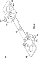
FIGs. 6A-6C are representative perspective views of a terminal assembly along with endbells and endbell portions, which are part of thefuse assembly 500 ofFIG. 5 , according to exemplary embodiments.FIG. 6A features aterminal assembly 600A consisting of a fuse element disposed between two fuse terminals;FIG. 6B features theterminal assembly 600B having two attached endbells; andFIG. 6C features theterminal assembly 600C with an attached bottom first endbell portion and top second endbell portion (collectively, "terminal assembly 600"). - The
terminal assembly 600A (FIG. 6A ) consists of afuse element 608 disposed between afirst terminal 604a and asecond terminal 604b (collectively, "terminals 604"). Thefuse element 608 is shown as a simple, rectangular element having no bends or curves but may assume a variety of shapes and sizes, as the particular shape or size of thefuse element 608 is not meant to be limiting. In an exemplary embodiment, the terminals 604 and the fuse element are formed as a unitary metallic, conductive material, such as zinc, copper, silver, aluminum, or alloys or combinations thereof. The present disclosure is not limited in this regard. - In an exemplary embodiment, the
terminal assembly 600 features recesses disposed proximate to each terminal. Arecess 612a and arecess 612b are located on opposing sides of theterminal assembly 600 close to thefirst terminal 604a; similarly, arecess 612c and arecess 612d are located on opposing sides of theterminal assembly 600, close to thesecond terminal 604b (collectively, "recesses 612"). As illustrated inFIG. 6C , theendbell portion 610a includes aprojection 616 that mates with therecess 612b. The recesses 612 andprojections 616 facilitate connection of the endbells to theterminal assembly 600, in exemplary embodiments. Theprojections 616 are described in more detail in conjunction with the description ofFIG. 7A , below. -
Endbells FIG. 6B (collectively, "endbells 602"). In exemplary embodiments, each endbell 602 consists of two parts or halves. The first endbell 602a consists of afirst endbell portion 610a and asecond endbell portion 610b; thesecond endbell 602b consists of afirst endbell portion 610c and asecond endbell portion 610d (collectively, "endbell portions 610"). Theendbell portions 610 are designed to be engaged with respective surfaces of theterminal assembly 600 at the location of the lips 612 and theprojections 616. In an exemplary embodiment, theendbell portions 610 are formed of a zinc alloy. -
FIG. 6C shows thefirst endbell portion 610a of the first endbell 602a and thesecond endbell portion 610d of thesecond endbell 602b. In an exemplary embodiment, theendbell portions endbell portions 610 are disposed next to the terminal 604 at the location of the recesses 612. Described in more detail in conjunction with the descriptions ofFIGs. 7A-7B andFIGs. 8A-8B , below, theendbell portions 610 include features that enable first and second endbell portions (e.g., 610a and 610b of endbell 602a or 610c and 610d ofendbell 602b) to mate with one another. Further, the recesses 612 facilitate both placement of theendbell portions 610 and coupling of the endbell portions to theterminal assembly 600 of thefuse assembly 500. - Although
FIGs. 6B and6C showendbell portions 610, in an alternative embodiment, theterminal assembly 600 and thefuse assembly 500 may alternatively be fitted withendbell portions 810, as illustrated and described inFIGs. 8A and 8B , below. - In exemplary embodiments, the endbells 602 further include insertion pins (
FIGs. 6B and6C ). The first endbell 602a includesinsertion pins second endbell 602b includes insertion pins 614d, 614e, and 614f (collectively, "insertion pins 614"). In exemplary embodiments, each endbell 602 further includes a fourth insertion pin (not shown). In one embodiment, the insertion pins 614 are made of a metal or metal alloy, such as zinc alloy. The number of insertion pins may vary. In one embodiment, eachendbell portion 610 includes two insertion pins 614. In an exemplary embodiment, the insertion pins 614 enable connection between the endbells 602 and the fuse body 106 (see alsoFIG. 5 ). The insertion pins 614 are described in more detail in in conjunction with the description ofFIG. 12 , below. -
FIGs. 7A and 7B are representative drawings ofendbell portion 610 andendbell portion coupling 700, respectively, according to exemplary embodiments.FIG. 7A shows anendbell portion 610;FIG. 7B shows a cross-sectional view of theendbell portion coupling 400 for thefuse assembly 500 ofFIG. 5 . Because eachendbell portion 610 is substantially similar to each other endbell portion, whether disposed on top, on bottom, on the left side, or on the right side, of theterminal assembly 600, the various features of the endbell portions are also substantially similar. - Each
endbell portion 610 includes afeature surface 720, including a raisedportion 718, asemi-circular surface 722 at a circumferential edge of the endbell portion, and twoflat side surfaces Side surface 724a shows anendbell aperture 732, which is a transverse cylindrical void visible on either side of theendbell portion 610. Theendbell aperture 732 is used to fill thefuse assembly 500 with sand or other material once the two endbells are connected to the fuse body, after which the aperture is sealed with plugs on both sides (FIGs. 5 and6B ). - In exemplary embodiments, the
feature surface 720 includes aprotrusion 728 while the raisedportion 718 of thefeature surface 720 includes areceptacle 730. Thereceptacle 730 of oneendbell portion 610 is designed to receive theprotrusion 728 of a second endbell portion, thereby mating the two endbell portions. In exemplary embodiments, when the mating occurs, the raisedportion 718 is raised up, relative to thefeature surface 720, thus allowing room for theterminal assembly 600 to be disposed between the twoendbell portions 610. - First introduced in
FIG. 6C , theprojection 616 of the raisedportion 718 extends into thefeature surface 720. In exemplary embodiments, the recesses 612 of theterminal assembly 600 mate withrespective projections 616 of theendbell portion 610 so that the endbell portions can successfully mate with theterminal assembly 600. The recesses 612 andprojections 616 thus provide a guide for positioning of theendbell portions 610 upon the upper and lower surfaces of theterminal assembly 600. Designers of ordinary skill in the art will recognize that the recesses 612 andprojections 616 may vary in shape and size, while still providing the desired mating properties to theendbell portions 610. - In exemplary embodiments, the
feature surface 720 further features twocrush ribs endbell portions 610 are engaged with one another, thecrush rib 726a of the first endbell portion (e.g.,endbell portion 610b,FIG. 6B ) is disposed directly over the crush rib of the second endbell portion (e.g.,endbell portion 610a), with theterminal assembly 600 disposed between the two endbell portions, thus forming a seal between the endbell portions and the terminal assembly. Similarly, thecrush rib 726b of the one endbell portion is disposed directly over a second crush rib of another endbell portion. In exemplary embodiments, theprojection 616 facilitates placement of the eachendbell portion 610 upon theterminal assembly 600. - In exemplary embodiments, the
protrusion 728 of theendbell portion 610 further includes one or more ribs.Ribs FIG. 7A (collectively, "ribs 736"), though there may be more or fewer ribs than are shown. The ribs 736 on theprotrusion 728 are another engagement feature which deform in thereceptacle 730 during assembly to retain the relative positions of the twoendbell portions 610. Thus, when theendbells 610 are engaged with one another, the ribs 736, like the crush ribs 726, facilitate melding of the respective components together, resulting in an air-tight coupling and formation of a seal between the endbells 602 without use of adhesive. The recesses 612 andprojections 616 similarly help seal theendbell portions 610 against theterminal assembly 600. - In exemplary embodiments, as illustrated in the cross-sectional view of
FIG. 7B , when the twoendbell portions 610 are engaged with and radially secured to one another, the crush ribs 726 mate with theterminal assembly 600 and deform. First andsecond crush ribs endbell portion 610b and third and fourth crush ribs 726c and 726d forendbell portion 610a are shown. Theterminal assembly 600, which may be made from copper or copper alloy, is pressed firmly against the zinc or zinc alloy material of theendbell portions 610, such that some compression and/or deformation of the two materials occurs. The optional ribs 736 also facilitate the fixed coupling of the twoendbell portions 610. In an exemplary embodiment, the pressure of connecting the crush ribs 726 with theterminal assembly 600 produces a sealed envelope between the contents of thefuse assembly 500 and the external environment. - In an exemplary embodiment, the
endbell portions 610 are pressed around theterminal assembly 600 during manufacture, resulting in a concentric circular endbell on each end of the fuse (FIGs. 5 and6B ). The features of each endbell portion 610 (theprotrusions 728 and the receptacles 730) can be used to align the two endbell portions while theprojection 616 of each endbell portion is used to "locate" respective recesses 612 on theterminal assembly 600. - In exemplary embodiments, once mated, the two
endbell portions 610 become fixably attached without using an adhesive or sealant. This eliminates the need for endbell/terminal surface regularity. The crush ribs 726 in theendbell portions 610 bite into theterminal assembly 600, deforming material in both the endbell portions and the terminal assembly. Thus, if the surface of either theendbell portion 610 or theterminal assembly 600 is not perfectly flat, the engagement interface can still make a firm seal between the two materials. In an exemplary embodiment, the intentional interference of the crush ribs 726 with the surfaces of theterminal assembly 600 provides mechanical support and a fixed connection betweenendbell portions 610 and the terminal assembly. Further, in an exemplary embodiment, the pressure of connecting the crush ribs 726 the terminal assembly surfaces produces a sealed envelope between the fuse contents and the external environment. -
FIGs. 8A and 8B are representative drawings ofendbell portion 810, according to exemplary embodiments.FIG. 8A is a perspective view andFIG. 8B is a cross-sectional view of theendbell portion 810. Theendbell portion 810 may be part of thefuse assembly 500 ofFIG. 5 . Theendbell portion 810 features afeature surface 820 with a raisedportion 818, where thefeature surface 820 includes aprotrusion 828 and the raised portion includes areceptacle 830. Theprotrusion 828 andreceptacle 830 facilitate connection of theendbells 610 to theterminal assembly 600, in exemplary embodiments. Theendbell portion 810 also features aprojection 816. Theprojection 816 is designed to mate with the recess 612 of the terminal assembly 600 (FIG. 6C ). The recesses 612 andprojections 816 facilitate positioning guidance when connecting the endbell portions to theterminal assembly 600, in exemplary embodiments. - As with the endbell 610 (
FIGs. 7A and 7B ), theendbell 810 also features twocrush ribs endbell portions 810 are engaged with one another, such as by press-fitting, thecrush rib 826a of the upper endbell portion is disposed directly over the crush rib of the lower endbell portion, with theterminal assembly 600 disposed between the two endbell portions. Similarly, thecrush rib 826b of the upper endbell portion is disposed directly over a second crush rib of the lower endbell portion. In exemplary embodiments, the two crush ribs 826, along with theprojection 816, facilitate placement of the eachendbell portion 810 upon theterminal assembly 600. - Further, in exemplary embodiments, the
endbell 810 features troughs which are adjacent to the crush ribs 826.Trough 844a is adjacent to crushrib 826a whiletrough 844b is adjacent to crushrib 826b (collectively, "troughs 844"). In the cross-sectional view ofFIG. 8B , the crush ribs 826 are shown as projections while the troughs 844 are shown as depressions. When theendbell portions 810 are engaged together, sometimes the crush ribs 826 are substantially compressed and/or deformed, such that the excess material of the compression/deformation is able to fit into the troughs 844. Where the compression/deformation causes a smaller interference, there may be less excess material, rendering the troughs 844 unused. Theendbell portion 810 thus offers additional flexibility for the assembly of thefuse assembly 500. The mating elements of thenovel fuse assembly 500, different from those of thefuse assembly 100, also provide both secure affixation of the endbells to the fuse body and provide positioning guidance during assembly for ease of manufacturing the fuse assembly. -
FIGs. 9A and 9B are representative drawings ofendbell portion coupling 900, according to exemplary embodiments.FIG. 9A is a perspective view andFIG. 9B is a cross-sectional view of theendbell portion coupling 900. Aterminal assembly 902 is shown disposed between afirst endbell portion 910a and asecond endbell portion 910b (collectively, "endbell portions 910"). The elements shown inFIGs. 9A and 9B may be part of the fuse assembly 500 (FIG. 5 ). Thesecond endbell portion 910b, though showing fewer features, is substantially similar to thefirst endbell portion 910a, in exemplary embodiments. Theterminal assembly 902 shares some similarities to theaforementioned terminal assemblies aforementioned endbell portions - The endbell portions 910 feature both a
protrusion 928 and areceptacle 930. Theprotrusion 928 of one endbell portion 910 is designed to fit into the receptacle of a second endbell portion. Theterminal assembly 902 features arecess 912a and arecess 912b (collectively, "recesses 912"), which are disposed on opposing edges of the terminal assembly. Thebottom endbell portion 910a shows aprojection 916, and theendbell portion 910b, which is substantially similar toendbell portion 910a, also includes a projection. Theseprojections 916 are designed to mate with respective recesses 912 of theterminal assembly 902, in exemplary embodiments. When the two endbell portions 910 are engaged with one another, theprojection 916 of theendbell portion 910a will fit into therecess 912a, with the recess (not shown) of theendbell portion 912b fitting into therecess 912b. - In exemplary embodiments, the
endbell portion 910a further includes a pair ofcrush ribs crush rib 926a is disposed on either side oftrough crush rib 926b is disposed on either side oftrough - In exemplary embodiments, the
terminal assembly 902 includes mating grooves for coupling with the crush ribs 926 of the endbell portions 910. On a first surface of theterminal assembly 902, afirst mating groove 942a is in one side of the recesses 912 and asecond mating groove 942b is in another side of the recesses; on a second surface of the terminal assembly, athird mating groove 942c is in one side of the recesses and asecond mating groove 942d is in another side of the recesses (collectively, "mating grooves 942"). In exemplary embodiments, the mating grooves 942 are spaced a distance, d, apart and the crush ribs 926 are also spaced a distance, d, apart. The mating grooves 942 of theterminal assembly 902 are thus receiving structures for mating with the crush ribs 926 of the endbell portions 910. - The
terminal assembly 902, which may be made from copper or copper alloy, is pressed firmly against the zinc or zinc alloy material of the endbell portions 910, such that some compression and possibly deformation of the two materials occurs. In an exemplary embodiment, the pressure of connecting the crush ribs 926 against respective mating grooves 942 of the terminal assembly 910 produces a sealed envelope between the contents of the fuse assembly and the external environment. The crush ribs 926 and the mating grooves 942 facilitate melding of the respective components together, resulting in an air-tight coupling into the endbells without use of adhesive. The recesses 912 andprojections 916 similarly help seal the endbell portions 910 against theterminal assembly 902. - In exemplary embodiments, the
projection 916 of the endbell portions 910 and the recesses 912 of theterminal assembly 902 provide positioning guidance during manufacture of thefuse assembly 500. With the addition of mating grooves 942 in theterminal assembly 902, this positioning guidance is enhanced, in exemplary embodiments, as the crush ribs 926 of the endbell portions 910 are able to "find" the mating grooves of theterminal assembly 902 for ease of manufacturing the fuse assembly. - The fuse assemblies described above feature insertion pins, which are used to secure the endbells to the fuse body. In legacy fuse assemblies, cylindrical holes are drilled into both the endbells and the fuse body. The holes retain the endbells axially within the cylindrical tube of the fuse body.
-
FIG. 10 is an illustration of a legacy drilling process of a fuse assembly according to the prior art. The drilling operation can be quite messy and may cause contamination inside the fuse assembly, which can negatively impact operation of the fuse element. For example, conductive materials from the drilling operation, if left inside the fuse assembly, may cause current to flow between the two terminals, even though the fuse element has been broken due to a fault condition. The material from the drilling operation may thus cause the fuse to not function as designed. - To retain the endbells at opposing ends of the fuse, holes are to be drilled radially to a specified depth through the fuse body and into the endbells. Metal pins are then inserted into the holes, rigidly retaining the endbells in place. Drilling into most fuse body materials is fast, efficient, and does not easily dull the drill bit. Drilling a blind hole into the endbell portion is risky because there is uncertainty about whether the drill hole is in the correct location. Further, drilling a blind hole into zinc is difficult, slow, and dulls the drill bit quickly and damages the drill bit with high regularity, which poses a problem for mass production. Because they are made from zinc or zinc alloy, drilling holes in the
endbell portions - As an alternative to drilling, the endbell portions may be made using molding operations, such as injection molding. The core and cavity are the shaped sections in either half of the mold tool that give the endbell portion its final shape. The cylindrical holes used for the insertion pins can be molded in this way.
- There may be drawbacks with using molding operations for the cylindrical holes, however.
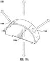
FIG. 11A is a representative drawing of an endbell portion with cylindrical holes, in accordance with exemplary embodiments.Endbell portion 1100 may be similar toendbell portions 210 offuse assembly 100 orendbell portions 610 or 910 offuse assembly 500. Twocylindrical holes endbell portion 1100, forming radial cavities (collectively, "holes 1104"). - The upward vertical arrow indicates tool cavity pull while the downward vertical arrow indicates tool core pull of the molding operation. The diagonal arrows indicate tooling slide for the holes 1104. Unfortunately, during the tooling of the holes 1104, an interrupted surface profile, given by parting
lines - Adding diecast/molded holes (as opposed to slots) require additional slides to be added to the tool, which in turn create an inconsistent surface due to the additional parting-lines. As this is the mating surface between the endbell exterior and the body interior, a consistent surface for the endbell is preferred.
FIG. 11A thus shows an inefficient tooling layout. The diagonal lines indicate tooling "slides" that are not aligned with the tool pulling direction, which adds both cost and additional parting lines to the final part. - As an alternative, in exemplary embodiments, the endbells are formed in a molding operation with slots, rather than cylindrical holes. The slots are designed specifically to eliminate the need to add side actions in the molding tool and maintain a smooth uninterrupted endbell surface.
-
FIG. 11B is a representative drawing of an endbellportion having slots 1150, in accordance with exemplary embodiments. Using a molding operation rather than drilling, twoslots FIG. 1 ) and fuse body 506 (FIG. 5 ), are also made using a molding process with the holes being part of the core and cavity of the fuse body, thus eliminating the need to drill holes in the fuse body. - Parting
lines slot 1112a andparting lines slot 1112b (collectively, "parting lines 1114"). In contrast to the parting lines 1106 inFIG. 11A , the parting lines 1114 ofendbell 1110 do not affect the surface of the endbell, but only the slots themselves, which will receive insertion pins during assembly. The alternative molding operation ofFIG. 11B thus ensures a consistent minimally interrupted surface profile for improved assembly to the fuse body, in some embodiments.FIG. 11B thus shows the improved tooling layout, relative to that ofFIG. 11A , in exemplary embodiments. By using slots rather than cylindrical holes, the slots are produced by tooling with the same pull direction as the rest of the tool. -
FIG. 12 is a representative exploded perspective drawing of afuse assembly 1200 featuring endbells with pre-molded alignment slots, according to exemplary embodiments. Afuse body 1206 and a cross-section of asingle endbell 1202 are shown. Theendbell 1202 may be a two-part endbell, such as the endbells 102 and 502 of thefuse assemblies Fuse terminals fuse body 1206. - The
fuse body 1206 includesfuse body holes endbell 1202, as well asfuse body hole 1216e, shown on the opposing side of the fuse body, for securing a second endbell (not shown) (collectively "fuse body holes 1216"). - In exemplary embodiments, diecast/molded slots of predetermined size and orientation are located on each
endbell 1202, removing the need to drill.Alignment slots endbell 1202, such as is shown inFIG. 11B (collectively, "alignment slots 1212" or "slots 1212"). The cross-sectional view shows that the slots 1212 are somewhat trapezoid-shaped, with the top of the slots near the circumferential surface of theendbell 1202 being wider than at the bottom, in some embodiments. Visible in thealignment slot 1212b, aslot bottom 1218 is circular, in some embodiments, though shown as a semi-circle in the cross-sectional view. - Also featured in the
fuse assembly 1200 areinsertion pins endbell 1202 as well asinsertion pins fuse body hole 1216c andslot 1212c for the endbell 1202 and for the not visible endbell. In one embodiment, the insertion pins 1214 are made of a metal or metal alloy material, such as stainless steel. In an exemplary embodiment, four insertion pins 1214 are used to secure each endbell, though the number of insertion pins may vary. - Together, the fuse body holes 1216 and the slots 1212 receive the insertion pins 1214 to secure the
endbell 1202 and not visible endbell to thefuse body 1206. The pre-cast/pre-molded alignment slots 1212 significantly simplify the fuse manufacturing process by removing the need to drill into the fuse endbells without adding tooling complexity. Using slots 1212 in the endbells 1202 (rather than cylindrical holes) allow the endbell tooling to remain basic with simple core/cavity blocks, avoiding costly side-action features in the tooling. The use of slots thus minimally impacts tooling cost and piece part cycle time, in some embodiments. Further, having pre-cast/pre-molded endbell slots allow for the fuse body to be independently drilled prior to assembly. - Further, in exemplary embodiments, the presence of the pre-cast/pre-molded alignment slots 1212 eliminates the risk of metal particulate entering the functional region of the fuse due to endbell drilling. The endbell slot design of
FIG. 12 both guides pin insertion alignment and permits the action of drilling holes into the fuse body to be performed at any time separately from the rest of the assembly, in exemplary embodiments. - As used herein, an element or step recited in the singular and proceeded with the word "a" or "an" should be understood as not excluding plural elements or steps, unless such exclusion is explicitly recited. Furthermore, references to "one embodiment" of the present disclosure are not intended to be interpreted as excluding the existence of additional embodiments that also incorporate the recited features.
- While the present disclosure makes reference to certain embodiments, numerous modifications, alterations, and changes to the described embodiments are possible without departing from the sphere and scope of the present disclosure, as defined in the appended claims. Accordingly, it is intended that the present disclosure not be limited to the described embodiments, but that it has the full scope defined by the language of the following claims, and equivalents thereof.
Claims (15)
- A fuse assembly comprising:a fuse body;a terminal assembly disposed within the fuse body and having first and second opposing surfaces, the terminal assembly comprising a fuse element extending between a first terminal and a second terminal;an endbell to be coupled to the fuse body, the endbell comprising:a first endbell portion having a first crush rib engaging the first surface of the terminal assembly; anda second endbell portion having a second crush rib engaging the second surface of the terminal assembly, the first endbell portion and the second endbell portion being fastened to one another with the terminal assembly sandwiched therebetween, the first crush rib and the second crush rib forming a seal around the terminal assembly.
- The fuse assembly of claim 1, wherein the first endbell portion further comprisesa first receptacle formed therein anda first protrusion extending therefrom, and the second endbell comprises a second receptacle formed therein and a second protrusion extending therefrom, wherein the first protrusion matingly engages the second receptacle and the second protrusion matingly engages the first receptacle, preferably wherein the first crush rib is disposed on a surface of the first endbell portion intermediate the first receptacle and the first protrusion.
- The fuse assembly of claim 1 or 2, further comprising:a first slot formed in a circumferential edge of the first endbell portion;a second slot formed in a circumferential edge of the second endbell portion;a first hole formed in the fuse body;a second hole formed in the fuse body;a first insertion pin extending through the first hole and the first slot; anda second insertion pin extending through the second hole and the second slot;wherein the first and second insertion pins secure the endbell to the fuse body.
- The fuse assembly of any of the preceding claims with one or more of the following:wherein the first endbell portion is identical to the second endbell portion;wherein the endbell is formed of a zinc alloy material;wherein the first crush rib is deformed into the first surface and the second crush rib is deformed into the second surface to form an air-tight seal between the first endbell portion, the terminal assembly, and the second endbell portion.
- The fuse assembly of any of the preceding claims, further comprising:first and second mating grooves in the first surface of the terminal assembly;third and fourth mating grooves in the second surface of the terminal assembly;a third crush rib on the first endbell portion; anda fourth crush rib on the second endbell portion;wherein the first crush rib mates with the first mating groove, the second crush rib mates with the second mating groove, the third crush rib mates with the third mating groove and the fourth crush rib mates with the fourth mating groove.
- The fuse assembly of any of the preceding claims, the first endbell portion further comprising:
a first feature surface comprising a first raised portion and a first protrusion, the first raised portion defining a first receptacle. - The fuse assembly of claim 6, the second endbell portion further comprising a second feature surface comprising a second raised portion and a second protrusion, the second raised portion defining a second receptacle, wherein the second protrusion engages the first receptacle and the first protrusion engages the second receptacle in response to the first endbell portion being fastened to the second endbell portion.
- The fuse assembly of any of the preceding claims, further comprising a plurality of troughs disposed adjacent to respective crush ribs for allowing excess material from each crush rib to flow into a respective trough in when the first endbell portion is fastened to the second endbell portion.
- The fuse assembly of any of the preceding claims, further comprising:a first slot formed in a circumferential edge of the first endbell portion;a second slot formed in a circumferential edge of the second endbell portion;a first hole formed in the fuse body;a second hole formed in the fuse body;a first insertion pin extending through the first hole and the first slot; anda second insertion pin extending through the second hole and the second slot;wherein the first and second insertion pins secure the endbell to the fuse body.
- An endbell adapted to secure a terminal assembly within a fuse body, the endbell comprising:a first endbell portion comprising a first protrusion, a first receptacle, and a first crush rib, wherein the first crush rib is adapted to engage a first surface of the terminal assembly ; anda second endbell portion comprising a second protrusion, a second receptacle, and a second crush rib, wherein the second crush rib is adapted to engage a second surface of the terminal assembly opposite the first surface;wherein the first protrusion engages the second receptacle and the second protrusion engages the first receptacle to form a seal around the terminal assembly.
- The endbell of claim 10, further comprising:a first lip seat formed on the first protrusion; anda second lip seat formed on the second protrusion;wherein a first lip of the terminal assembly is formed on the first lip seat and a second lip of the terminal assembly is formed on the second lip seat.
- The endbell of claim 11, the first protrusion further comprising a first lip seat and the second protrusion further comprising a second lip seat, wherein a first lip of the terminal assembly mates with the first lip seat and a second lip of the terminal assembly mates with the second lip seat in response to the first endbell portion being fastened to the second endbell portion.
- The endbell of any of the claims 10-12, the first endbell portion further comprising:a feature surface having a raised portion; anda third crush rib, wherein the first crush rib is formed on an edge of the feature surface and the third crush rib is formed on a second edge of the feature surface;wherein the first protrusion is disposed on the feature surface and the first receptacle is disposed on the raised portion, preferably wherein a projection extends from the raised portion, the projection to mate with a recess of the terminal assembly.
- The endbell of any of the claims 10-13, further comprising:a first slot formed in a circumferential edge of the first endbell portion;a second slot formed in a second circumferential edge of the second endbell portion;wherein a first insertion pin is inserted into a first cylindrical hole of a fuse body and the first slot and a second insertion pin is inserted into a second cylindrical hole of the fuse body and the second slot to secure the endbell to the fuse body.
- A fuse assembly comprising:a fuse body comprising a first hole and a second hole, wherein the fuse body is molded with the first and second holes;a first endbell portion molded with a first slot, wherein the first slot is formed radially into a circumferential edge of the first endbell portion forming a radial cavity therethrough;a second endbell portion molded with a second slot, wherein the second slot is formed radially into a circumferential edge of the second endbell portion forming a radial cavity therethrough; anda first insertion pin extending through the first hole and the first slot; anda second insertion pin extending through the second hole and the second slot;wherein the first and second insertion pins secure the first and second endbell portions to the fuse body,preferably further comprising a terminal assembly disposed within the fuse body, the terminal assembly comprising a fuse element extending between a first terminal and a second terminal, wherein the first endbell portion and the second endbell portion are fastened to one another with the terminal assembly sandwiched therebetween, the first endbell and the second endbell forming a seal around the terminal assembly.
Applications Claiming Priority (1)
| Application Number | Priority Date | Filing Date | Title |
|---|---|---|---|
| US17/314,277 US11289297B1 (en) | 2021-05-07 | 2021-05-07 | Two-piece fuse endbell with pre-cast/pre-molded alignment slots and optional interface crush ribs |
Publications (3)
| Publication Number | Publication Date |
|---|---|
| EP4095880A2 true EP4095880A2 (en) | 2022-11-30 |
| EP4095880A3 EP4095880A3 (en) | 2023-02-08 |
| EP4095880B1 EP4095880B1 (en) | 2024-12-11 |
Family
ID=80855481
Family Applications (1)
| Application Number | Title | Priority Date | Filing Date |
|---|---|---|---|
| EP22170569.2A Active EP4095880B1 (en) | 2021-05-07 | 2022-04-28 | Two-piece fuse endbell with interface crush ribs |
Country Status (4)
| Country | Link |
|---|---|
| US (2) | US11289297B1 (en) |
| EP (1) | EP4095880B1 (en) |
| JP (1) | JP7753625B2 (en) |
| CN (1) | CN115312362A (en) |
Families Citing this family (1)
| Publication number | Priority date | Publication date | Assignee | Title |
|---|---|---|---|---|
| WO2023032829A1 (en) * | 2021-09-03 | 2023-03-09 | デクセリアルズ株式会社 | Protective element |
Family Cites Families (24)
| Publication number | Priority date | Publication date | Assignee | Title |
|---|---|---|---|---|
| GB2124043B (en) * | 1982-07-17 | 1985-03-13 | Brush Fusegear Ltd | Electrical fuselink |
| US4949062A (en) * | 1989-04-24 | 1990-08-14 | Cooper Industries, Inc. | Fuse having a non-electrically conductive end bell |
| US4972170A (en) * | 1989-04-24 | 1990-11-20 | Cooper Industries, Inc. | High speed fuse |
| US4949063A (en) * | 1989-04-24 | 1990-08-14 | Cooper Industries, Inc. | End closure system for high speed fuse |
| JPH06103879A (en) * | 1992-09-18 | 1994-04-15 | Nec Kansai Ltd | Lead cutter device |
| US5296832A (en) * | 1993-04-23 | 1994-03-22 | Gould Inc. | Current limiting fuse |
| US5357234A (en) * | 1993-04-23 | 1994-10-18 | Gould Electronics Inc. | Current limiting fuse |
| US6486766B1 (en) * | 2000-03-14 | 2002-11-26 | Littlefuse, Inc. | Housing for double-ended fuse |
| JP2005026188A (en) * | 2003-07-03 | 2005-01-27 | Koa Corp | Current fuse and manufacturing method of current fuse |
| EP1797576A4 (en) * | 2004-09-15 | 2008-12-10 | Littelfuse Inc | High voltage/high current fuse |
| KR101165328B1 (en) * | 2011-07-29 | 2012-07-18 | 한국단자공업 주식회사 | High voltage fuse |
| JP5675859B2 (en) * | 2013-01-28 | 2015-02-25 | 太平洋精工株式会社 | fuse |
| CN106663575B (en) * | 2014-05-16 | 2018-11-13 | 釜屋电机株式会社 | Chip fuse and its manufacturing method |
| US11075047B2 (en) | 2014-05-28 | 2021-07-27 | Eaton Intelligent Power Limited | Compact high voltage power fuse and methods of manufacture |
| US11075048B2 (en) * | 2014-05-28 | 2021-07-27 | Eaton Intelligent Power Limited | Compact high voltage power fuse and methods of manufacture |
| US10224166B2 (en) | 2014-11-14 | 2019-03-05 | Littelfuse, Inc. | High-current fuse with endbell assembly |
| US9761402B2 (en) * | 2014-11-14 | 2017-09-12 | Littelfuse, Inc. | High-current fuse with endbell assembly |
| DE202015101840U1 (en) * | 2015-04-15 | 2015-04-30 | Inter Control Hermann Köhler Elektrik GmbH & Co. KG | Fuse component |
| JP6426056B2 (en) * | 2015-06-08 | 2018-11-21 | 豊田鉄工株式会社 | fuse |
| JP2017117565A (en) * | 2015-12-22 | 2017-06-29 | 太平洋精工株式会社 | Manufacturing method for fuse, and fuse |
| US10978267B2 (en) * | 2016-06-20 | 2021-04-13 | Eaton Intelligent Power Limited | High voltage power fuse including fatigue resistant fuse element and methods of making the same |
| US10290458B2 (en) * | 2016-08-24 | 2019-05-14 | Littelfuse, Inc. | Fuse and method of forming a fuse |
| JP6494833B2 (en) | 2018-04-16 | 2019-04-03 | 太平洋精工株式会社 | Fuse manufacturing method and fuse |
| US11101093B2 (en) * | 2019-01-21 | 2021-08-24 | Littelfuse, Inc. | Fuses and methods of forming fuses |
-
2021
- 2021-05-07 US US17/314,277 patent/US11289297B1/en active Active
- 2021-11-18 US US17/530,038 patent/US11651923B2/en active Active
-
2022
- 2022-04-18 JP JP2022068045A patent/JP7753625B2/en active Active
- 2022-04-28 EP EP22170569.2A patent/EP4095880B1/en active Active
- 2022-05-07 CN CN202210492519.0A patent/CN115312362A/en active Pending
Also Published As
| Publication number | Publication date |
|---|---|
| US11651923B2 (en) | 2023-05-16 |
| JP7753625B2 (en) | 2025-10-15 |
| US20220359144A1 (en) | 2022-11-10 |
| EP4095880A3 (en) | 2023-02-08 |
| EP4095880B1 (en) | 2024-12-11 |
| JP2022173087A (en) | 2022-11-17 |
| US11289297B1 (en) | 2022-03-29 |
| CN115312362A (en) | 2022-11-08 |
Similar Documents
| Publication | Publication Date | Title |
|---|---|---|
| EP0970545B1 (en) | Electrical connector with insert molded housing | |
| US8840436B2 (en) | Electrically conducting terminal | |
| EP2362493B1 (en) | Female terminal and production method of female terminal | |
| US9343825B2 (en) | Connector | |
| EP3326245A1 (en) | Terminal fitting | |
| EP4095880B1 (en) | Two-piece fuse endbell with interface crush ribs | |
| EP2451016B1 (en) | Female terminal | |
| US20180090900A1 (en) | Method for manufacturing female terminal and female terminal | |
| CN101128960B (en) | Surface mount header assembly having a planar alignment surface | |
| CN111817105B (en) | Method for manufacturing male power terminal and male power terminal | |
| US7140927B2 (en) | Electrical contact terminal comprising an elastic contact blade | |
| US9780502B2 (en) | Electrical plug connector for a safety restraint system | |
| US20130137315A1 (en) | Crimp terminal | |
| EP2916395B1 (en) | Moulding tool | |
| US11152733B2 (en) | Flat electrical connector for supplemental restraint system | |
| CN110313110B (en) | Electrical Terminals and Connector Assemblies | |
| EP2672572B1 (en) | Electrical connection system that includes an integrally formed retaining means to secure a sealing member disposed therein | |
| JP6082547B2 (en) | Busbar insert resin molded product manufacturing method | |
| US9647378B1 (en) | Electrical connector | |
| US20070037457A1 (en) | Female electrical contact element and method for making a female electrical contact element | |
| EP1689033B1 (en) | A male terminal fitting, a plate material therefor and a method of forming it | |
| US9923327B2 (en) | Exchangeable crimping die insert for a crimping die | |
| DE102015007536B4 (en) | Socket terminal, spring assembly for contacting a contact plate with a mating contact and method of forming a socket terminal | |
| EP3609025B1 (en) | Method for securing a terminal within a connector housing of a connector assembly | |
| US11721511B2 (en) | Fuse terminal design |
Legal Events
| Date | Code | Title | Description |
|---|---|---|---|
| PUAI | Public reference made under article 153(3) epc to a published international application that has entered the european phase |
Free format text: ORIGINAL CODE: 0009012 |
|
| STAA | Information on the status of an ep patent application or granted ep patent |
Free format text: STATUS: THE APPLICATION HAS BEEN PUBLISHED |
|
| AK | Designated contracting states |
Kind code of ref document: A2 Designated state(s): AL AT BE BG CH CY CZ DE DK EE ES FI FR GB GR HR HU IE IS IT LI LT LU LV MC MK MT NL NO PL PT RO RS SE SI SK SM TR |
|
| PUAL | Search report despatched |
Free format text: ORIGINAL CODE: 0009013 |
|
| AK | Designated contracting states |
Kind code of ref document: A3 Designated state(s): AL AT BE BG CH CY CZ DE DK EE ES FI FR GB GR HR HU IE IS IT LI LT LU LV MC MK MT NL NO PL PT RO RS SE SI SK SM TR |
|
| RIC1 | Information provided on ipc code assigned before grant |
Ipc: H01H 85/153 19900101ALN20230105BHEP Ipc: H01H 85/165 19900101ALI20230105BHEP Ipc: H01H 69/02 19680901AFI20230105BHEP |
|
| STAA | Information on the status of an ep patent application or granted ep patent |
Free format text: STATUS: REQUEST FOR EXAMINATION WAS MADE |
|
| 17P | Request for examination filed |
Effective date: 20230804 |
|
| RBV | Designated contracting states (corrected) |
Designated state(s): AL AT BE BG CH CY CZ DE DK EE ES FI FR GB GR HR HU IE IS IT LI LT LU LV MC MK MT NL NO PL PT RO RS SE SI SK SM TR |
|
| GRAP | Despatch of communication of intention to grant a patent |
Free format text: ORIGINAL CODE: EPIDOSNIGR1 |
|
| STAA | Information on the status of an ep patent application or granted ep patent |
Free format text: STATUS: GRANT OF PATENT IS INTENDED |
|
| RIC1 | Information provided on ipc code assigned before grant |
Ipc: H01H 85/153 20060101ALN20240704BHEP Ipc: H01H 85/165 20060101ALI20240704BHEP Ipc: H01H 69/02 20060101AFI20240704BHEP |
|
| INTG | Intention to grant announced |
Effective date: 20240719 |
|
| P01 | Opt-out of the competence of the unified patent court (upc) registered |
Free format text: CASE NUMBER: APP_46588/2024 Effective date: 20240812 |
|
| GRAS | Grant fee paid |
Free format text: ORIGINAL CODE: EPIDOSNIGR3 |
|
| GRAA | (expected) grant |
Free format text: ORIGINAL CODE: 0009210 |
|
| STAA | Information on the status of an ep patent application or granted ep patent |
Free format text: STATUS: THE PATENT HAS BEEN GRANTED |
|
| AK | Designated contracting states |
Kind code of ref document: B1 Designated state(s): AL AT BE BG CH CY CZ DE DK EE ES FI FR GB GR HR HU IE IS IT LI LT LU LV MC MK MT NL NO PL PT RO RS SE SI SK SM TR |
|
| REG | Reference to a national code |
Ref country code: GB Ref legal event code: FG4D |
|
| REG | Reference to a national code |
Ref country code: CH Ref legal event code: EP |
|
| REG | Reference to a national code |
Ref country code: IE Ref legal event code: FG4D |
|
| REG | Reference to a national code |
Ref country code: DE Ref legal event code: R096 Ref document number: 602022008534 Country of ref document: DE |
|
| REG | Reference to a national code |
Ref country code: LT Ref legal event code: MG9D |
|
| PG25 | Lapsed in a contracting state [announced via postgrant information from national office to epo] |
Ref country code: HR Free format text: LAPSE BECAUSE OF FAILURE TO SUBMIT A TRANSLATION OF THE DESCRIPTION OR TO PAY THE FEE WITHIN THE PRESCRIBED TIME-LIMIT Effective date: 20241211 |
|
| PG25 | Lapsed in a contracting state [announced via postgrant information from national office to epo] |
Ref country code: FI Free format text: LAPSE BECAUSE OF FAILURE TO SUBMIT A TRANSLATION OF THE DESCRIPTION OR TO PAY THE FEE WITHIN THE PRESCRIBED TIME-LIMIT Effective date: 20241211 |
|
| PG25 | Lapsed in a contracting state [announced via postgrant information from national office to epo] |
Ref country code: BG Free format text: LAPSE BECAUSE OF FAILURE TO SUBMIT A TRANSLATION OF THE DESCRIPTION OR TO PAY THE FEE WITHIN THE PRESCRIBED TIME-LIMIT Effective date: 20241211 |
|
| REG | Reference to a national code |
Ref country code: NL Ref legal event code: MP Effective date: 20241211 |
|
| PG25 | Lapsed in a contracting state [announced via postgrant information from national office to epo] |
Ref country code: ES Free format text: LAPSE BECAUSE OF FAILURE TO SUBMIT A TRANSLATION OF THE DESCRIPTION OR TO PAY THE FEE WITHIN THE PRESCRIBED TIME-LIMIT Effective date: 20241211 |
|
| PG25 | Lapsed in a contracting state [announced via postgrant information from national office to epo] |
Ref country code: NO Free format text: LAPSE BECAUSE OF FAILURE TO SUBMIT A TRANSLATION OF THE DESCRIPTION OR TO PAY THE FEE WITHIN THE PRESCRIBED TIME-LIMIT Effective date: 20250311 |
|
| PG25 | Lapsed in a contracting state [announced via postgrant information from national office to epo] |
Ref country code: LV Free format text: LAPSE BECAUSE OF FAILURE TO SUBMIT A TRANSLATION OF THE DESCRIPTION OR TO PAY THE FEE WITHIN THE PRESCRIBED TIME-LIMIT Effective date: 20241211 Ref country code: GR Free format text: LAPSE BECAUSE OF FAILURE TO SUBMIT A TRANSLATION OF THE DESCRIPTION OR TO PAY THE FEE WITHIN THE PRESCRIBED TIME-LIMIT Effective date: 20250312 |
|
| PG25 | Lapsed in a contracting state [announced via postgrant information from national office to epo] |
Ref country code: RS Free format text: LAPSE BECAUSE OF FAILURE TO SUBMIT A TRANSLATION OF THE DESCRIPTION OR TO PAY THE FEE WITHIN THE PRESCRIBED TIME-LIMIT Effective date: 20250311 |
|
| PG25 | Lapsed in a contracting state [announced via postgrant information from national office to epo] |
Ref country code: NL Free format text: LAPSE BECAUSE OF FAILURE TO SUBMIT A TRANSLATION OF THE DESCRIPTION OR TO PAY THE FEE WITHIN THE PRESCRIBED TIME-LIMIT Effective date: 20241211 |
|
| REG | Reference to a national code |
Ref country code: AT Ref legal event code: MK05 Ref document number: 1751073 Country of ref document: AT Kind code of ref document: T Effective date: 20241211 |
|
| PG25 | Lapsed in a contracting state [announced via postgrant information from national office to epo] |
Ref country code: SM Free format text: LAPSE BECAUSE OF FAILURE TO SUBMIT A TRANSLATION OF THE DESCRIPTION OR TO PAY THE FEE WITHIN THE PRESCRIBED TIME-LIMIT Effective date: 20241211 |
|
| PG25 | Lapsed in a contracting state [announced via postgrant information from national office to epo] |
Ref country code: PL Free format text: LAPSE BECAUSE OF FAILURE TO SUBMIT A TRANSLATION OF THE DESCRIPTION OR TO PAY THE FEE WITHIN THE PRESCRIBED TIME-LIMIT Effective date: 20241211 |
|
| PGFP | Annual fee paid to national office [announced via postgrant information from national office to epo] |
Ref country code: DE Payment date: 20250305 Year of fee payment: 4 |
|
| PG25 | Lapsed in a contracting state [announced via postgrant information from national office to epo] |
Ref country code: IS Free format text: LAPSE BECAUSE OF FAILURE TO SUBMIT A TRANSLATION OF THE DESCRIPTION OR TO PAY THE FEE WITHIN THE PRESCRIBED TIME-LIMIT Effective date: 20250411 |
|
| PG25 | Lapsed in a contracting state [announced via postgrant information from national office to epo] |
Ref country code: PT Free format text: LAPSE BECAUSE OF FAILURE TO SUBMIT A TRANSLATION OF THE DESCRIPTION OR TO PAY THE FEE WITHIN THE PRESCRIBED TIME-LIMIT Effective date: 20250411 |
|
| PG25 | Lapsed in a contracting state [announced via postgrant information from national office to epo] |
Ref country code: EE Free format text: LAPSE BECAUSE OF FAILURE TO SUBMIT A TRANSLATION OF THE DESCRIPTION OR TO PAY THE FEE WITHIN THE PRESCRIBED TIME-LIMIT Effective date: 20241211 |
|
| PG25 | Lapsed in a contracting state [announced via postgrant information from national office to epo] |
Ref country code: RO Free format text: LAPSE BECAUSE OF FAILURE TO SUBMIT A TRANSLATION OF THE DESCRIPTION OR TO PAY THE FEE WITHIN THE PRESCRIBED TIME-LIMIT Effective date: 20241211 Ref country code: AT Free format text: LAPSE BECAUSE OF FAILURE TO SUBMIT A TRANSLATION OF THE DESCRIPTION OR TO PAY THE FEE WITHIN THE PRESCRIBED TIME-LIMIT Effective date: 20241211 |
|
| PG25 | Lapsed in a contracting state [announced via postgrant information from national office to epo] |
Ref country code: SK Free format text: LAPSE BECAUSE OF FAILURE TO SUBMIT A TRANSLATION OF THE DESCRIPTION OR TO PAY THE FEE WITHIN THE PRESCRIBED TIME-LIMIT Effective date: 20241211 |
|
| PG25 | Lapsed in a contracting state [announced via postgrant information from national office to epo] |
Ref country code: CZ Free format text: LAPSE BECAUSE OF FAILURE TO SUBMIT A TRANSLATION OF THE DESCRIPTION OR TO PAY THE FEE WITHIN THE PRESCRIBED TIME-LIMIT Effective date: 20241211 |
|
| PG25 | Lapsed in a contracting state [announced via postgrant information from national office to epo] |
Ref country code: SE Free format text: LAPSE BECAUSE OF FAILURE TO SUBMIT A TRANSLATION OF THE DESCRIPTION OR TO PAY THE FEE WITHIN THE PRESCRIBED TIME-LIMIT Effective date: 20241211 |
|
| REG | Reference to a national code |
Ref country code: DE Ref legal event code: R097 Ref document number: 602022008534 Country of ref document: DE |
|
| PG25 | Lapsed in a contracting state [announced via postgrant information from national office to epo] |
Ref country code: DK Free format text: LAPSE BECAUSE OF FAILURE TO SUBMIT A TRANSLATION OF THE DESCRIPTION OR TO PAY THE FEE WITHIN THE PRESCRIBED TIME-LIMIT Effective date: 20241211 |
|
| PLBE | No opposition filed within time limit |
Free format text: ORIGINAL CODE: 0009261 |
|
| STAA | Information on the status of an ep patent application or granted ep patent |
Free format text: STATUS: NO OPPOSITION FILED WITHIN TIME LIMIT |
|
| REG | Reference to a national code |
Ref country code: CH Ref legal event code: L10 Free format text: ST27 STATUS EVENT CODE: U-0-0-L10-L00 (AS PROVIDED BY THE NATIONAL OFFICE) Effective date: 20251022 |
|
| 26N | No opposition filed |
Effective date: 20250912 |
|
| REG | Reference to a national code |
Ref country code: CH Ref legal event code: H13 Free format text: ST27 STATUS EVENT CODE: U-0-0-H10-H13 (AS PROVIDED BY THE NATIONAL OFFICE) Effective date: 20251125 |
|
| PG25 | Lapsed in a contracting state [announced via postgrant information from national office to epo] |
Ref country code: LU Free format text: LAPSE BECAUSE OF NON-PAYMENT OF DUE FEES Effective date: 20250428 |
|
| PG25 | Lapsed in a contracting state [announced via postgrant information from national office to epo] |
Ref country code: MC Free format text: LAPSE BECAUSE OF FAILURE TO SUBMIT A TRANSLATION OF THE DESCRIPTION OR TO PAY THE FEE WITHIN THE PRESCRIBED TIME-LIMIT Effective date: 20241211 |
|
| REG | Reference to a national code |
Ref country code: BE Ref legal event code: MM Effective date: 20250430 |
|
| PG25 | Lapsed in a contracting state [announced via postgrant information from national office to epo] |
Ref country code: BE Free format text: LAPSE BECAUSE OF NON-PAYMENT OF DUE FEES Effective date: 20250430 |
|
| PG25 | Lapsed in a contracting state [announced via postgrant information from national office to epo] |
Ref country code: CH Free format text: LAPSE BECAUSE OF NON-PAYMENT OF DUE FEES Effective date: 20250430 |
|
| PG25 | Lapsed in a contracting state [announced via postgrant information from national office to epo] |
Ref country code: IE Free format text: LAPSE BECAUSE OF NON-PAYMENT OF DUE FEES Effective date: 20250428 |
|
| PGFP | Annual fee paid to national office [announced via postgrant information from national office to epo] |
Ref country code: IT Payment date: 20260320 Year of fee payment: 5 |
|
| PGFP | Annual fee paid to national office [announced via postgrant information from national office to epo] |
Ref country code: FR Payment date: 20260309 Year of fee payment: 5 |