EP4095803A1 - Image processing method and apparatus - Google Patents
Image processing method and apparatus Download PDFInfo
- Publication number
- EP4095803A1 EP4095803A1 EP21744269.8A EP21744269A EP4095803A1 EP 4095803 A1 EP4095803 A1 EP 4095803A1 EP 21744269 A EP21744269 A EP 21744269A EP 4095803 A1 EP4095803 A1 EP 4095803A1
- Authority
- EP
- European Patent Office
- Prior art keywords
- calibration image
- code
- calibration
- position mark
- decoding
- Prior art date
- Legal status (The legal status is an assumption and is not a legal conclusion. Google has not performed a legal analysis and makes no representation as to the accuracy of the status listed.)
- Pending
Links
Images





Classifications
-
- G—PHYSICS
- G06—COMPUTING OR CALCULATING; COUNTING
- G06T—IMAGE DATA PROCESSING OR GENERATION, IN GENERAL
- G06T7/00—Image analysis
- G06T7/80—Analysis of captured images to determine intrinsic or extrinsic camera parameters, i.e. camera calibration
-
- G—PHYSICS
- G06—COMPUTING OR CALCULATING; COUNTING
- G06T—IMAGE DATA PROCESSING OR GENERATION, IN GENERAL
- G06T7/00—Image analysis
- G06T7/60—Analysis of geometric attributes
-
- G—PHYSICS
- G06—COMPUTING OR CALCULATING; COUNTING
- G06T—IMAGE DATA PROCESSING OR GENERATION, IN GENERAL
- G06T9/00—Image coding
-
- G—PHYSICS
- G06—COMPUTING OR CALCULATING; COUNTING
- G06V—IMAGE OR VIDEO RECOGNITION OR UNDERSTANDING
- G06V10/00—Arrangements for image or video recognition or understanding
- G06V10/20—Image preprocessing
- G06V10/22—Image preprocessing by selection of a specific region containing or referencing a pattern; Locating or processing of specific regions to guide the detection or recognition
- G06V10/225—Image preprocessing by selection of a specific region containing or referencing a pattern; Locating or processing of specific regions to guide the detection or recognition based on a marking or identifier characterising the area
-
- G—PHYSICS
- G06—COMPUTING OR CALCULATING; COUNTING
- G06V—IMAGE OR VIDEO RECOGNITION OR UNDERSTANDING
- G06V10/00—Arrangements for image or video recognition or understanding
- G06V10/20—Image preprocessing
- G06V10/28—Quantising the image, e.g. histogram thresholding for discrimination between background and foreground patterns
-
- G—PHYSICS
- G06—COMPUTING OR CALCULATING; COUNTING
- G06V—IMAGE OR VIDEO RECOGNITION OR UNDERSTANDING
- G06V10/00—Arrangements for image or video recognition or understanding
- G06V10/40—Extraction of image or video features
- G06V10/46—Descriptors for shape, contour or point-related descriptors, e.g. scale invariant feature transform [SIFT] or bags of words [BoW]; Salient regional features
-
- H—ELECTRICITY
- H04—ELECTRIC COMMUNICATION TECHNIQUE
- H04N—PICTORIAL COMMUNICATION, e.g. TELEVISION
- H04N19/00—Methods or arrangements for coding, decoding, compressing or decompressing digital video signals
- H04N19/44—Decoders specially adapted therefor, e.g. video decoders which are asymmetric with respect to the encoder
-
- G—PHYSICS
- G06—COMPUTING OR CALCULATING; COUNTING
- G06T—IMAGE DATA PROCESSING OR GENERATION, IN GENERAL
- G06T2207/00—Indexing scheme for image analysis or image enhancement
- G06T2207/10—Image acquisition modality
- G06T2207/10024—Color image
-
- G—PHYSICS
- G06—COMPUTING OR CALCULATING; COUNTING
- G06T—IMAGE DATA PROCESSING OR GENERATION, IN GENERAL
- G06T2207/00—Indexing scheme for image analysis or image enhancement
- G06T2207/30—Subject of image; Context of image processing
- G06T2207/30204—Marker
-
- G—PHYSICS
- G06—COMPUTING OR CALCULATING; COUNTING
- G06T—IMAGE DATA PROCESSING OR GENERATION, IN GENERAL
- G06T2207/00—Indexing scheme for image analysis or image enhancement
- G06T2207/30—Subject of image; Context of image processing
- G06T2207/30248—Vehicle exterior or interior
- G06T2207/30252—Vehicle exterior; Vicinity of vehicle
Definitions
- This application relates to the field of image technologies, and in particular, to an image processing method and apparatus.
- Camera calibration is a basis of machine vision, and quality of a calibration result directly determines system precision of machine vision.
- a self-driving vehicle is used as an example.
- the self-driving vehicle relies on a plurality of sensors to sense an ambient environment.
- a video camera on the self-driving vehicle plays an important role.
- the video camera can provide necessary information for safe driving of the vehicle by analyzing an image.
- Intrinsic parameters of the video camera are determined in a manufacture process. The intrinsic parameters are accurate, and there is little individual difference. Extrinsic parameters of the video camera are greatly affected by installation. Therefore, the extrinsic parameters are calibrated usually after the video camera is installed on the vehicle.
- This application provides an image processing method and apparatus, to simply, quickly, and accurately determine a position of a positioning point of a calibration image. In this way, a decoding rate can be improved.
- an image processing method may include: collecting a calibration image, where the calibration image includes a position mark that indicates a positioning point of the calibration image; and decoding the calibration image based on the calibration image and the position mark.
- the calibration image carries position information, so that a decoder side determines the positioning point of the calibration image.
- the position mark is carried in the calibration image, that is, the decoder side is notified of the position mark that is of the positioning point and that is carried in the calibration image.
- the decoder side can simply, quickly, and accurately determine a position of the positioning point based on the calibration image.
- the position of the positioning point of the calibration image is determined based on the position mark, so that the decoder side can quickly identify the position of the positioning point.
- a decoding rate is increased, and decoding duration is reduced.
- the position mark is marked by using different colors.
- the position of the positioning point of the calibration image is marked by using different colors. In this way, the position of the positioning point can be identified conveniently and quickly.
- the position mark is marked by a corner point of a black-and-white checkerboard.
- the position mark may be formed by the black-and-white checkerboard, and the corner point of the checkerboard may be used to represent the position of the positioning point of the calibration image.
- the decoding the calibration image based on the calibration image and the position mark includes: determining the positioning point of the calibration image based on the position mark; and decoding the calibration image based on the positioning point of the calibration image and the calibration image.
- the decoding the calibration image based on the calibration image and the position mark includes: obtaining, based on the calibration image and the position mark, a positioning point through rough extraction; and performing sub-pixelization processing on the positioning point obtained through rough extraction, to determine the positioning point of the calibration image.
- the positioning point of the calibration image may be determined. That is, an approximate positioning point may be extracted first, and then the positioning point is precisely searched for. In this way, positioning precision can be improved. For example, the positioning precision can reach a sub-pixel level.
- the decoding the calibration image based on the calibration image and the position mark includes: obtaining, based on the calibration image and the position mark, a binary code corresponding to the calibration image; and determining a code direction of the calibration image based on a position of a preset sequence in the binary code.
- the code direction of the calibration image may be determined according to a preset rule, for example, a relationship between the position of the preset sequence and the code direction.
- a start position of a calibration image code may be determined according to the preset rule.
- the preset sequence is located on a most significant bit or a least significant bit of the code.
- the preset sequence is located on the most significant bit or the least significant bit of the code.
- the decoder side may determine that the position of the preset sequence is the most significant bit or the least significant bit of the code.
- a code string may include only one preset sequence.
- the code string may include a unique preset sequence.
- a code direction can be quickly determined based on a correspondence between the unique preset sequence and the position (for example, a least significant bit of the code or a most significant bit of the code).
- the decoding the calibration image based on the calibration image and the position mark includes: decoding the calibration image based on the calibration image and the position mark under M threshold conditions, to obtain M decoding results, where M is an integer greater than or equal to 2; and determining a decoding result that appears most frequently in the M decoding results as a decoding result of the calibration image.
- a plurality of constraint conditions that is, threshold conditions
- a stricter constraint condition indicates higher decoding reliability.
- a plurality of scales are used for binarization processing, and identification results obtained at different scales may be clustered based on an accurate position mark. An accurate decoding result and a pixel position may be obtained through voting. In this way, a probability of incorrect detection can be reduced, and a detection probability can be improved.
- a contour of the calibration image is circular.
- code points may be arranged on an inner ring and an outer ring. In such an arrangement manner, space can be effectively used, and a distance between adjacent code points can be maximized.
- an image processing method may include: collecting a calibration image; obtaining a binary code corresponding to the calibration image; determining a code direction of the calibration image based on a position of a preset sequence in the binary code; and decoding the calibration image based on the code direction of the calibration image.
- the code direction of the calibration image may be determined according to a preset rule, for example, a relationship between the position of the preset sequence and the code direction.
- a start position of a calibration image code may be determined according to the preset rule.
- the preset sequence is located on a most significant bit or a least significant bit of the code.
- the preset sequence is located on the most significant bit or the least significant bit of the code.
- a decoder side may determine that the position of the preset sequence is the most significant bit or the least significant bit of the code.
- a code string may include only one preset sequence.
- the code string may include a unique preset sequence.
- a code direction can be quickly determined based on a correspondence between the unique preset sequence and the position (for example, a least significant bit of a code or a most significant bit of the code).
- an image processing method may include: obtaining a code value; and generating a calibration image based on the code value, where the calibration image includes a position mark that is used to indicate a position of a positioning point of the calibration image.
- the position mark when the calibration image or a code pattern is generated, the position mark may be carried in the calibration image, that is, a decoder side is notified of position information that is of the positioning point and that is carried in the calibration image.
- the decoder side can simply, quickly, and accurately determine the position of the positioning point based on the calibration image. In this way, an accurate decoding result can be obtained, and decoding duration can be reduced.
- the position mark is marked by using different colors.
- the position mark is marked by a positioning point of a black-and-white checkerboard.
- the generating a calibration image based on the code value includes: generating the calibration image based on a binary code corresponding to the code value, where a position of a preset sequence in the binary code is used to determine a code direction of the calibration image.
- the preset sequence is located on a most significant bit or a least significant bit of a code.
- a contour of the calibration image is circular.
- the calibration image includes N code points, where N is an integer greater than or equal to 1; and the generating a calibration image includes: arranging the N code points on an inner ring and an outer ring, to generate the calibration image.
- an image processing method may include: obtaining a code value; and generating a calibration image based on a binary code corresponding to the code value, where a position of a preset sequence in the binary code is used to determine a code direction of the calibration image.
- the code direction of the calibration image may be determined according to a preset rule, for example, a relationship between the position of the preset sequence and the code direction.
- a start position of a calibration image code may be determined according to the preset rule.
- the preset sequence is located on a most significant bit or a least significant bit of the code.
- an image processing apparatus configured to implement the methods provided in the first aspect to the fourth aspect.
- the apparatus may include a module configured to implement the methods according to the first aspect to the fourth aspect.
- an image processing apparatus includes a memory and a processor.
- the memory is configured to store instructions
- the processor is configured to execute the instructions stored in the memory, so that the apparatus is enabled to implement the methods provided in the first aspect to the fourth aspect.
- a chip includes a processing module and a communications interface.
- the processing module is configured to control the communications interface to perform external communication, and the processing module is further configured to implement the methods provided in the first aspect to the fourth aspect.
- a computer-readable storage medium stores a computer program; and when the computer program is executed by an apparatus, the apparatus is enabled to implement the methods provided in the first aspect to the fourth aspect, and any one of the possible implementations of the first aspect to the fourth aspect.
- a computer program product including instructions is provided.
- an apparatus is enabled to implement the methods provided in the first aspect to the fourth aspect.
- the computer program product may run a computer program on an in-vehicle computing platform for self-driving.
- a calibration image carrying a position mark is provided.
- a decoder side is notified of position information that is of a positioning point and that is carried in the calibration image.
- the decoder side can simply, quickly, and accurately determine a position of the positioning point based on the calibration image. In this way, an accurate decoding result can be obtained, and decoding duration can be reduced.
- the technical solutions in embodiments of this application can be applied to various communications systems, for example, communication in an Interne of Vehicles system, device to device (device to device, D2D) communication, machine to machine (machine to machine, M2M) communication, machine type communication (machine type communication, MTC), a 5th generation (5th generation, 5G) system, or new radio (new radio, NR).
- Communication modes in the Internet of vehicles system are collectively referred to as V2X (where X represents everything).
- V2X communication includes vehicle-to-vehicle (vehicle to vehicle, V2V) communication, vehicle-to-infrastructure (vehicle to infrastructure, V2I) communication, vehicle-to-pedestrian (vehicle to pedestrian, V2P) communication, or vehicle-to-network (vehicle to network, V2N) communication.
- V2V vehicle to vehicle
- V2I vehicle to infrastructure
- V2P vehicle-to-pedestrian
- V2N vehicle-to-network
- Each type of load cell has a three-dimensional rectangular coordinate system.
- coordinate origins and directions of three coordinate axes of the cells may be inconsistent.
- Extrinsic parameter calibration mainly includes determining three translation parameters and three rotation angle parameters between spatial rectangular coordinate systems.
- Intrinsic camera parameters include a parameter related to a camera feature.
- An intrinsic camera parameter may be determined by installation positions of an optical lens and a photoelectric sensor in a module.
- the intrinsic camera parameter may include but is not limited to a focal length, a pixel size, an optical distortion, a white balance parameter, resolution and contrast, a flare, a dark angle, and the like.
- Extrinsic camera parameter Each type of load cell has a three-dimensional rectangular coordinate system.
- a main purpose of extrinsic camera parameter calibration is to obtain a pose relationship between a coordinate system of a camera and a coordinate system of a vehicle body, which is usually composed of three rotation angles and three translation components, or may be represented by a rotation matrix.
- PnP algorithm A PnP (perspective-n-point, PnP) problem is calculating a camera pose or an object pose when pairs of n spatial 3D points and corresponding 2D points in an image are given. The camera pose and object pose are corresponding. Generally, the least square solution exists when n is greater than 3. In actual calibration, a plurality of points are used to determine an optimal solution by using an iteration method.
- Embodiments of this application are applied to a scenario of extrinsic parameter calibration of a self-driving vehicle.
- FIG. 1 is a schematic diagram of an application scenario to which an embodiment of this application is applied.
- FIG. 1 is a schematic diagram of a calibration workshop of a self-driving vehicle.
- a wheel positioning apparatus can determine a spatial position of the vehicle.
- Processing such as image collection and extrinsic parameter result calculation can be implemented with an in-vehicle computing platform.
- FIG. 2 is a schematic diagram of another application scenario to which an embodiment of this application is applied.
- a plurality of video cameras are provided for a self-driving vehicle.
- Automatic, fast, and accurate extrinsic camera parameter calibration is an important part of intelligent vehicle manufacture.
- a solution applied by many vehicle manufacturers is that a station is added at an end of a production line and a calibration image is placed at a specified position for calibration, which is shown in Figure 2 .
- a four-wheel positioning apparatus can determine a spatial position of the vehicle.
- a world coordinate system may be constructed by using a total station, and the four-wheel positioning apparatus may determine a matrix of the vehicle relative to the world coordinate system based on a wheel position, so as to determine the spatial position of the vehicle.
- An in-vehicle computing platform can drive a to-be-calibrated camera to collect and decode a calibration image on a calibration board, and calculate extrinsic parameters of all cameras.
- An identification speed and identification precision of the calibration image have great impact on calibration efficiency and calibration accuracy of a calibration result.
- This application provides a manner in which a calibration pattern carries information indicating a position of an image corner point, for example, a position mark, so that the calibration image can be quickly and accurately identified.
- Embodiments of this application may be further applied to joint calibration of a camera and another sensor such as a radar or a millimeter-wave radar.
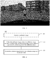
- FIG. 3 is a schematic diagram of another application scenario to which an embodiment of this application is applied.
- FIG. 3 shows a result of projecting a laser point cloud into an image after calibration.
- FIG. 1 to FIG. 3 are merely examples for description, and this application is not limited thereto.
- embodiments of this application can be further applied to any scenario in which image content needs to be identified.
- FIG. 4 is a schematic block diagram of an image processing method 400 according to an embodiment of this application.
- the method 400 may include the following steps.
- 410 Collect a calibration image, where the calibration image includes a position mark, and the position mark is used to indicate a position of a positioning point of the calibration image.
- the calibration image is merely a name, and does not limit the protection scope of embodiments of this application.
- the calibration image is used in the following description. It should be understood that all calibration images in the following description may be replaced with images, or all calibration images in the following description may be replaced with code images, or all calibration images in the following description may be replaced with calibration patterns, or all calibration images in the following description may be replaced with code patterns.
- Step 410 collecting the calibration image may be understood as collecting, by a decoder side, a calibration image collected by a video camera or camera.
- the method 400 may further include Step 401.
- an encoder side may generate the calibration image, and the calibration image generated by the encoder side includes a position mark indicating a positioning point of the calibration image.
- the positioning point for example, may also be referred to as a corner point or a position. This is not limited herein. In the following description, the positioning point is used for description.
- a calibration image carrying a position mark is provided.
- the decoder side is notified of position information that is of the positioning point and that is carried in the calibration image.
- the decoder side can simply, quickly, and accurately determine a position of the positioning point based on the calibration image. In this way, an accurate decoding result can be obtained, and decoding duration can be reduced.
- the following first describes the position information of the positioning point.
- the position information is used to indicate information about the position of the positioning point in the calibration image. Because the position information is carried in the calibration image, the decoder side can quickly determine the position of the positioning point of the calibration image based on the position information carried in the calibration image.
- the position information may be indicated by the position mark in the calibration image.
- the position of the positioning point of the calibration image is determined based on the position mark, so that the decoder side can quickly identify the position of the positioning point. As a result, a decoding rate is increased, and decoding duration is reduced. It should be understood that using a position mark is merely a possible implementation, and any manner in which position information of a positioning point can be calibrated in a calibration image falls within the protection scope of this embodiment of this application.
- the position mark may be implemented in a plurality of forms, and a position mark of any form that can mark the position of the positioning point of the calibration image can be applied to this embodiment of this application.
- a specific form of the position mark is not limited in this embodiment of this application. Any method that can be applied to mark the position of the positioning point of the calibration image falls within the protection scope of this embodiment of this application.
- Example 1 The position mark may be marked by using different colors.
- the position mark is marked by a corner point of a black-and-white checkerboard.
- the position mark may be formed by a black-and-white checkerboard, and a corner point of the checkerboard represents the position of the positioning point of the calibration image.
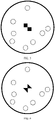
- FIG. 5 and FIG. 6 show two possible forms of the calibration image as examples.
- the position mark may be determined based on a contact point of two black squares in the center of the calibration image.
- the two black squares in the center may be used to represent the positioning point of the calibration image, and the contact point of the two black squares represents the positioning point of the calibration image. It can be learned that a layout of the two black squares and a surrounding white background is similar to a black-and-white checkerboard.
- the corner point of the black-and-white checkerboard that is, the contact point of the two black squares in FIG. 5 , may be used to represent the positioning point of the calibration image.
- a dot may represent a code point.
- code points may be arranged on an inner ring and an outer ring. In such an arrangement manner, space can be effectively used, and a distance between adjacent code points can be maximized.
- the code points may be arranged on the inner ring and the outer ring, or the code points may be evenly arranged on one ring. This is not limited.
- positions of dots (namely, the code points) in FIG. 5 do not constitute any limitation on the protection scope of this embodiment of this application. In practice, a position of a code point may be determined based on an actual situation.
- a contour of the calibration image may be a circle.
- the contact point of the two black squares in the center may overlap with a center of a contour circle.
- the calibration image is composed of the code points and the position mark.
- FIG. 5 is merely an example for description, and does not constitute any limitation on the protection scope of this embodiment of this application.
- the contour or the code points of the calibration image may alternatively be in another shape.
- contour of the calibration image is a circle and the code points are dots is used in the following description.
- the position mark may be determined based on a contact point of two black triangles in the center of the calibration image.
- the two black triangles in the center may be used to represent the positioning point of the calibration image, and the contact point of the two black triangles represents the positioning point of the calibration image. It can be learned that a layout of the two black triangles and a surrounding white background is similar to a black-and-white checkerboard. A corner point of the black-and-white checkerboard, that is, the contact point of the two black triangles in FIG. 6 , may be used to represent the positioning point of the calibration image.
- a dot may represent a code point.
- code points may be arranged on an inner ring and an outer ring.
- positions of dots (namely, the code points) in FIG. 6 do not constitute any limitation on the protection scope of this embodiment of this application. In practice, a position of a code point may be determined based on an actual situation.
- the contour of the calibration image may be a circle.
- the contact point of the two black triangles in the center may overlap with a center of a contour circle.
- the calibration image is composed of the code points and the position mark.
- FIG. 6 is merely an example for description, and does not constitute any limitation on the protection scope of this embodiment of this application.
- the contour or the code points of the calibration image may alternatively be in another shape.
- the position of the positioning point of the calibration image is marked by using different colors. In this way, the position of the positioning point can be identified conveniently and quickly.
- the position mark may be marked by a cross point.
- the position mark is marked by a cross point in the center of the calibration image.
- FIG 7 shows a possible form as an example.
- the position mark may be determined based on the cross point in the center of the calibration image.
- a dot may represent a code point.
- code points may be arranged on an inner ring and an outer ring.
- positions of dots (namely, the code points) in FIG. 7 do not constitute any limitation on the protection scope of this embodiment of this application. In practice, a position of a code point may be determined based on an actual situation.
- a contour of the calibration image may be a circle.
- the cross point in the center may overlap with a center of a contour circle.
- the calibration image is composed of the code points and the position mark.
- FIG. 7 is merely an example for description, and does not constitute any limitation on the protection scope of this embodiment of this application.
- the contour or the code points of the calibration image may alternatively be in another shape.
- Example 2 may be used in combination with Example 1.
- the position of the positioning point of the calibration image is marked by the cross point. This is simple for the encoder side to achieve. In addition, for the decoder side, the position of the positioning point of the calibration image can be conveniently and quickly identified.
- Example 1 and Example 2 are merely two examples for description, and a specific shape of the position mark is not limited. Any manner in which information that indicates a position of a positioning point is carried in a calibration image falls within the protection scope of embodiments of this application.
- the following describes a manner of determining the positioning point of the calibration image based on the position mark.
- the positioning point of the calibration image may be determined through rough positioning point extraction and precise positioning point extraction.
- two steps namely, rough extraction and precise extraction may be performed. That is, an approximate positioning point may be extracted first, and then the positioning point is precisely searched for. In this way, positioning precision can be improved. For example, the positioning precision can reach a sub-pixel level.
- sub-pixelization processing may be performed on a positioning point obtained through rough extraction, to determine a positioning point obtained through precise extraction.
- a final precise corner point may be calculated by using a sub-pixel contact point extraction algorithm. In this way, final positioning precision can reach a sub-pixel level.
- an accurate sub-pixel corner point is obtained based on a characteristic that a pixel gradient of an edge point is perpendicular to a vector of a sub-pixel corner point connected to the edge point.
- a sub-pixel corner point result obtained through precise positioning processing is shown as precise positioning in FIG. 10 .
- the decoder side may first perform rough positioning, for example, rough positioning shown in FIG. 10 .
- the decoder side may first transform the original image into a standard circle.
- a specific transformation manner is not limited in this embodiment of this application.
- Rough positioning point extraction that is, rough positioning
- the positioning point is a contact point of two black squares.
- the contact point is designed to overlap with the center of the contour circle of the calibration image. It should be understood that the positioning point may not overlap with a center of the standard circle, which is determined by transformation from the original image to the standard circle. However, the positioning point usually does not significantly deviate from the center of the standard circle.
- a result obtained through rough positioning is shown as rough positioning in FIG. 10 .
- An initial point that is, a contact point of two black squares in the rough positioning in FIG. 10
- vertexes of a search window that is, vertexes marked by four crosses in the rough positioning in FIG. 10
- precise positioning may be performed on a positioning point obtained through rough positioning, for example, precise positioning shown in FIG. 10 may be performed.
- the vertexes of the search window and the rough positioning point may be transformed into coordinates in the original image through inverse affine transformation.
- a final precise corner point can be calculated by using a sub-pixel contact point extraction algorithm. For example, by using an iterative method, an accurate sub-pixel corner point is obtained based on a characteristic that a pixel gradient of an edge point is perpendicular to a vector of a sub-pixel corner point connected to the edge point.
- a sub-pixel corner point result obtained through precise positioning processing is shown as the precise positioning in FIG. 10 .
- the foregoing example describes a position mark of a positioning point of a calibration image and a possible manner of determining the positioning point of the calibration image.
- the following describes a code direction of a calibration image.
- a code direction of a calibration image may be determined according to a preset rule.
- a start position of a calibration image code may be determined according to the preset rule.
- a least significant bit of a code may be denoted as a start bit, and a most significant bit of the code may be denoted as an end bit.
- a start bit corresponds to a least significant bit of a code
- an end bit corresponds to a most significant bit of the code.
- a code direction may be determined based on a position of a preset sequence.
- the code direction may be determined according to an arrangement rule of numbers.
- a position of the preset sequence may be specified in advance. Then a decoder side may determine the code direction based on the position of the preset sequence.
- the preset sequence is located on the most significant bit or the least significant bit of the code. In this way, the decoder side may determine that the position of the preset sequence is the most significant bit or the least significant bit of the code.
- the preset sequence represents a pre-specified sequence.
- a specific quantity of bits included in the preset sequence is not limited.
- the preset sequence may be 0001, 1000, 1100, 11010, 11000, 10100, 11100,011, 100, 110, or the like.
- the preset sequence may also be referred to as, for example, a particular subsequence.
- a name of the preset sequence does not constitute any limitation on the protection scope of this embodiment of this application.
- a code string may include only one preset sequence.
- the code string may include a unique preset sequence.
- a code direction can be quickly determined based on a correspondence between the unique preset sequence and the position (for example, a least significant bit of a code or a most significant bit of the code).
- Table 1 lists quantities of all positive integers that are less than or equal to 2 16 and that meet a condition that a corresponding preset sequence is included.
- Table 1 Preset sequence Quantity 0001, 1000, 1100 2031 0010, 1001,0100 1652 11010, 11000, 10100, 11100 1606 1010 1440 10001 1409 10010 1264 011, 100, 110 986
- the encoder side may complete encoding according to a preset sequence.
- a start bit corresponds to a least significant bit of a code
- an end bit corresponds to a most significant bit of the code
- a code corresponding to 4827 is 0001001011011011. Drawing starts from the start bit, and the least significant bit of the code is determined. If a number of the least significant bit is 1, a code point, for example, a code dot, may be drawn in a corresponding position. If the number of the least significant bit is 0, no code point is drawn. Code points on other bits are drawn in turn according to this rule.
- a result of encoding 4827 may be shown in FIG. 8 .
- dashed lines in FIG. 8 are marked for description, and may exist or may not exist in practice. This is not limited herein.
- FIG. 8 is merely an example pattern, and does not constitute any limitation on the protection scope of this embodiment of this application.
- the code direction may be determined based on the preset sequence.
- the preset sequence is located on the most significant bit of the code.
- the code direction is determined based on the preset sequence "0001". It is assumed that a preset rule is that the preset sequence is located on most significant bits, it may be determined that "0001" is located on the most significant four bits. Then circular shift of digit may be performed until "0001" is located on the most significant four bits, to obtain a decoding result.
- FIG. 9 shows this process.
- a 16-bit binary code may be obtained. For example, a result 1001011011011000 of the decimal number 4827 (the binary number 0001001011011011) may be obtained. In this case, circular shift of digit may be performed. For example, least significant three bits "000” are moved to a start position, that is, most significant bits. In this way, "0001" is located on most significant four bits.
- a sufficient encoding capacity can be provided on the premise of ensuring uniqueness.
- a code can be identified through simple calculation in a decoding process, and a decoding speed is high.
- decoding the calibration image based on the calibration image and the position information under M threshold conditions is performed, to obtain M decoding results, where M is an integer greater than or equal to 2.
- a code value and position information can be obtained under each threshold condition, for example, denoted as (ID, pos).
- ID represents a code result obtained through decoding under a threshold condition
- pos represents a position of a corresponding positioning point under the threshold condition.
- different scales may be used for binarization in image preprocessing, to adapt to different environment luminance and noise backgrounds.
- Most processes of decoding are processing a pattern obtained through binarization. Binarization is easily affected by luminance and background noise. Therefore, a finer scale can be used to prevent missing detection or incorrect detection of patterns in some excessively bright or dim scenarios.
- a plurality of data pairs in a form of (ID, pos) may be output through preprocessing at different scales. After rough extraction and precise extraction are performed on the position information (that is, pos), reliability of a result is high. Therefore, it is appropriate to classify data with close positions into a same group.
- a most reliable result is output through voting in a code group. For example, when voting is performed, some mechanisms may be selected to improve reliability, for example, a mechanism of outputting a result having a majority vote, to avoid false detection.
- a plurality of constraint conditions that is, threshold conditions
- a stricter constraint condition indicates higher decoding reliability.
- the plurality of scales are used for binarization processing, and identification results obtained at different scales may be clustered based on accurate position information. An accurate decoding result and a pixel position may be obtained through voting. In this way, a probability of incorrect detection can be reduced, and a detection probability can be improved.
- FIG. 11 is merely an example for description, and this embodiment of this application is not limited thereto.
- Image preprocessing may include but is not limited to grayscale conversion, filtering, binarization processing based on a plurality of scale thresholds, and contour extraction.
- a contour circle of the calibration image may be obtained through filtering according to the preset condition, so that an accurate result is obtained.
- one or more of the following aspects may be taken into account.
- a contour with an excessively small area may be screened out or filtered out. If a contour area is excessively small, a quantity of pixels contained in the contour area is small. This may increase a probability of incorrect detection.
- L represents a circumference
- Area represents an area
- eliipse represents roundness
- a more circular contour indicates smaller roundness; a less circular contour indicates larger roundness.
- Roundness of a standard circle is the smallest, which is 1.
- a contour whose roundness is within a specific range may be selected.
- a contour whose roundness is beyond the range is considered seriously deformed by default. To ensure that an identification result is accurate, the contour whose roundness is beyond the range can be removed.
- normal roundness when a projection angle is less than 70 degrees (70°), normal roundness may range from 1.0 to 1.5, and therefore the range may be set, for example, to [1.0, 1.5].
- Aspect 3 Contour concaveness and a quantity of edges for polygonal approximation of a contour
- Projection transformation does not change concaveness of an image, that is, a contour obtained through projection retains concaveness of an original image.
- a contour obtained through projection retains concaveness of an original image.
- an elliptical contour whose quantity of edges for polygonal approximation is usually greater than 10 may be selected.
- a contour of an outer circle has a plurality of child contours of a same level, and the child contours have no descendant contour.
- the contour may be checked whether a next contour exists. If a next contour exists, determining is performed on the next contour.
- ellipse fitting is performed on the selected contour, and the selected contour is transformed into a standard circle through affine transformation.
- contour includes n points, where n is an integer greater than or equal to 6.
- Least square fitting is performed on the points, and an objective function may be represented as the following Formula 3.
- Ellipse parameters A, B, C, D, and E may be obtained by substituting coordinates of the contour into formula 5. Therefore, a major axis a, a minor axis b, central coordinates, and a tilt angle of an ellipse may be obtained.
- a bounding rectangle of the ellipse may be converted into a square through affine transformation, and correspondingly, the ellipse is converted into a standard circle.
- the standard circle is a standard circle shown in (2) in FIG. 12 .
- u and v are coordinates before transformation
- x andy are coordinates after transformation
- at least three pairs of points are provided.
- u and v are vertex coordinates of the bounding rectangle of the ellipse and are solved for in the foregoing steps.
- the coordinates x andy are vertex coordinates of a bounding rectangle of the standard circle and can be solved for after a diameter d of the standard circle is specified, and the coordinates are (0,0), (d,0), (d,d), (0,d) when arranged clockwise.
- a center point of the contour circle and an edge length of a checkerboard may be determined in the standard circle, and coordinates in an original image may be obtained through inverse affine transformation.
- a positioning point is a contact point of two black squares.
- the contact point is designed to overlap with the center of the circle obtained based on the calibration image.
- Rough positioning point extraction is implemented in a standard circle image.
- the positioning point may not overlap with a center of the standard circle, which is due to an error of contour fitting and the nature of projection transformation. However, the positioning point usually does not significantly deviate from the center of the standard circle.
- a size ratio of the black square to the contour circle is fixed. Therefore, a size of the black square in the standard circle image can be obtained.
- the size ratio of the black square to the contour circle is denoted as ration.
- coordinates of four vertexes of a search window may be: x c ⁇ 2 L , y c ⁇ 2 L
- a result of rough positioning is shown in (3) in FIG. 12 , and an initial point and vertexes of the search window are depicted in the figure.
- a center point is used as a start point
- an oblique edge of the checkerboard is used as a window length to precisely search for checkerboard corner points.
- the search window and a rough positioning point may be transformed into coordinates in the original image through inverse affine transformation.
- a final precise corner point can be calculated by using a sub-pixel contact point extraction algorithm. For example, by using an iterative method, an accurate sub-pixel corner point is obtained based on a characteristic that a pixel gradient of an edge point is perpendicular to a vector of a sub-pixel corner point connected to the edge point.
- a sub-pixel corner point result obtained through precise positioning processing is shown in (4) in FIG. 12 .
- an accurate positioning point can be determined, in other words, positioning precision may reach a sub-pixel level.
- decoding of the calibration pattern may be performed based on a determined positioning point.
- a position of the positioning point is calculated in the foregoing steps, and then code content may be decoded. Detailed description is provided with reference to FIG. 13 .
- a standard circle image may be obtained, and the center of the standard circle is the positioning point.
- the calibration image is decoded in the standard circle image.
- a size of the contour circle and a size of the position mark in the contour circle are given.
- the two irrelevant areas may be first removed to prevent interference.
- all contours in a valid area may be extracted, and a qualified code point contour is obtained through filtering according to a preset condition.
- a contour area is taken into account in the preset condition. Because a code point diameter is designed to be in a fixed proportion to a contour circle diameter, a theoretical contour area of the code point can be obtained in the standard circle image. If an actual contour area is within a specific range, a contour with the actual contour area is used as a valid contour. For example, if the actual contour area is within a range of 0.5 to 1.5 times a theoretical area, a contour with the actual contour area may be used as a valid contour.
- included angles between centers of valid code contours and the center of the standard circle relative to a horizontal line are calculated, and may be ranked in order.
- the included angles may be ranked in ascending order.
- the included angles may be ranked in descending order. This is not limited. It should be understood that a specific ranking manner is not limited.
- the included angles may be ranked randomly.
- s represents a minimum resolution.
- ⁇ min represents a minimum angle in a rank.
- a 16-bit binary code can be obtained.
- a result of a decimal number 4827 (binary number 0001001011011011) may be 1001011011011000.
- Step 7 is performed.
- a final result is obtained by voting on code results and positions at all scales.
- a plurality of thresholds are used to perform binarization in the decoding process, and a code result and position information can be obtained under each threshold condition, which is denoted as, for example, (ID, pos).
- a code result and position information can be obtained under each threshold condition, which is denoted as, for example, (ID, pos).
- an error may occur in the decoding result under some threshold conditions, but a position obtained through rough extraction and precise extraction is accurate.
- voting is performed on identified content, and a final identification result is determined according to a principle of outputting a result having a majority vote. This process is shown in Table 2, and the final decoding result output according to the principle of outputting a result having a majority vote is 8183.
- embodiments of this application may be applied to extrinsic parameter calibration of a camera of a self-driving vehicle.
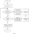
- a possible calibration process is shown in FIG. 14 .
- This embodiment of this application may be applied in Step 1410 of the calibration process.
- a spatial point and a pixel that are in a one-to-one correspondence can be obtained by using the encoding and decoding method provided in this embodiment of this application.
- the calibration process may include the following steps.
- Decode a collected calibration image and obtain, based on a calibration scenario parameter, pixel coordinates and world coordinates that are in a one-to-one correspondence.
- Step 1420 Calculate an extrinsic camera parameter of each camera based on a result of Step 1410.
- Step 1410 is described.
- the calibration scenario parameter is loaded first.
- the parameter may include but is not limited to: spatial positions of all code points determined by using a detection apparatus, a position of a wheel positioning apparatus, and the like.
- code content of the calibration image and two-dimensional pixel coordinates (that is, a positioning point) in the image may be determined.
- Step 2 is performed again to collect the calibration image and the wheel image.
- matching may be performed on the code points, and the pixel coordinates and the spatial coordinates that are in a one-to-one correspondence are obtained.
- Step 1420 The following describes Step 1420.
- a rotation matrix of the camera relative to the constructed world coordinate system may be calculated by using a PnP algorithm
- a four-wheel positioning apparatus may determine a rotation matrix of the vehicle relative to the world coordinate system, for example, denoted as W veh2world , based on a wheel position.
- a purpose of extrinsic parameter calibration is to calculate a transition matrix of a camera coordinate system relative to a vehicle body coordinate system.
- the transition matrix can perform transformation by using world coordinates constructed by a total station.
- Step 6 and Step 7 can be performed in any sequence.
- whether the pose of the camera relative to the world coordinate system is first calculated or the pose of the vehicle body relative to the world coordinate system is first calculated is not limited.
- FIG. 3 is used as an example.
- a result of joint calibration includes determining a rotation matrix of a laser coordinate system relative to a camera coordinate system. Therefore, a plurality of three-dimensional coordinates in the laser coordinate system and pixel coordinates matching the three-dimensional coordinates in an image are required.
- a calibration image carrying position information (for example, a position mark) provided in this embodiment of this application is used. It is assumed that a contour of the calibration image is a circle, and this feature is easy to be identified in a laser point cloud. For each frame of data, coordinates of a center of a circle of the image can be calculated. When there are a plurality of frames, joint calibration can be completed.
- FIG. 3 shows a result of projecting the laser point cloud into the image after calibration.
- a position mark is carried in a calibration image to indicate a position of a positioning point in the calibration image, which does not constitute any limitation on this application. Any manner in which position information of a positioning point is indicated in a calibration image falls within the protection scope of embodiments of this application.
- Embodiments described in this specification may be independent solutions, or may be combined based on internal logic. All these solutions fall within the protection scope of this application.
- a solution of determining a code direction based on a location of a preset sequence and a solution of carrying location information (for example, a location mark) in a calibration image may be used separately or may be used in combination.
- a calibration image carrying position information (for example, a position mark) is provided.
- a decoder side is notified of position information that is of a positioning point and that is carried in the calibration image.
- the decoder side can simply, quickly, and accurately determine a position of the positioning point based on the calibration image. In this way, an accurate decoding result can be obtained, and decoding duration can be reduced.
- precise extraction is performed on the positioning point, so that positioning precision can be improved.
- the positioning precision can reach a sub-pixel level.
- a code direction of a calibration image may be determined according to a preset rule.
- a start position of a calibration image code may be determined according to the preset rule.
- a plurality of constraint conditions (that is, threshold conditions) are set.
- a stricter constraint condition indicates higher decoding reliability.
- a plurality of scales are used for binarization processing, and identification results obtained at different scales may be clustered based on accurate position information. An accurate decoding result and a pixel position may be obtained through voting. In this way, a probability of incorrect detection can be reduced, and a detection probability can be improved.
- the methods and the operations implemented by the encoder side may alternatively be implemented by a component (for example, a chip or a circuit) used in an encoder side device
- the methods and the operations implemented by the decoder side may alternatively be implemented by a component (for example, a chip or a circuit) used in a decoder side device.
- each network element such as an encoder side device or a decoder side device, includes a corresponding hardware structure and/or software module for implementing each function.
- each network element such as an encoder side device or a decoder side device, includes a corresponding hardware structure and/or software module for implementing each function.
- a person skilled in the art may be aware that, in combination with units and algorithm steps of the examples described in embodiments disclosed in this specification, this application may be implemented by hardware or a combination of hardware and computer software. Whether a function is performed by hardware or hardware driven by computer software depends on particular applications and design constraints of the technical solutions. A person skilled in the art may use different methods to implement the described functions for each particular application, but it should not be considered that the implementation goes beyond the scope of this application.
- functional module division may be performed on the encoder side device or the decoder side device based on the foregoing method examples.
- various functional modules may be divided based on corresponding functions, or two or more functions may be integrated into one processing module.
- the integrated module may be implemented in a form of hardware, or may be implemented in a form of a software functional module.
- module division is an example, and is merely logical function division. In actual implementation, another division manner may be used.
- An example in which functional modules are divided based on corresponding functions is used below for description.
- FIG. 15 is a schematic block diagram of an image processing apparatus 1500 according to an embodiment of this application.
- the apparatus 1500 may include a transceiver module 1510 and a processing module 1520.
- the transceiver module 1510 may be configured to collect an image
- the processing module 1520 is configured to perform image processing.
- the apparatus 1500 may be a chip or a chip system.
- the transceiver module may be an input/output interface, an interface circuit, an output circuit, an input circuit, a pin, a related circuit, or the like on the chip or the chip system.
- the processing module may also be implemented as a processing circuit or a logic circuit.
- the apparatus 1500 may perform a step or a procedure performed by the decoder side device in the foregoing method embodiments, for example, may be the decoder side device, or a chip, a chip system, or a circuit disposed in the device.
- the transceiver module 1510 is configured to perform a collection-related operation of the decoder side device in the foregoing method embodiments
- the processing module 1520 is configured to perform a processing-related operation of the decoder side device in the foregoing method embodiments.
- the transceiver module 1510 is configured to collect a calibration image, where the calibration image includes a position mark that is used to indicate a position of a positioning point of the calibration image; and the processing module 1520 is configured to decode the calibration image based on the calibration image and the position mark.
- the position mark is marked by using different colors.
- the position mark is marked by a positioning point of a black-and-white checkerboard.
- the processing module 1520 is specifically configured to: determine the positioning point of the calibration image based on the position mark; and decode the calibration image based on the positioning point of the calibration image and the calibration image.
- the processing module 1520 is specifically configured to: obtain, based on the calibration image and the position mark, a positioning point obtained through rough extraction; and perform sub-pixelization processing on the positioning point obtained through rough extraction, to determine the positioning point of the calibration image.
- the processing module 1520 is specifically configured to: obtain, based on the calibration image and the position mark, a binary code corresponding to the calibration image; and determine a code direction of the calibration image based on a position of a preset sequence in the binary code.
- the preset sequence is located on a most significant bit or a least significant bit of a code.
- the processing module 1520 is specifically configured to: decode the calibration image based on the calibration image and the position mark under M threshold conditions, to obtain M decoding results, where M is an integer greater than or equal to 2; and determine a decoding result that appears most frequently in the M decoding results as a decoding result of the calibration image.
- a contour of the calibration image is circular.
- the transceiver module 1510 is configured to collect a calibration image; the processing module 1520 is configured to obtain a binary code corresponding to the calibration image, and determine a code direction of the calibration image based on a position of a preset sequence in the binary code; and the processing module 1520 is configured to decode the calibration image based on the code direction of the calibration image.
- the preset sequence is located on a most significant bit or a least significant bit of a code.
- the apparatus 1500 may perform steps or procedures performed by the decoder side device in the method 400 according to embodiments of this application.
- the apparatus 1500 may include units or modules configured to perform the methods performed by the decoder side device in FIG. 4 to FIG. 14 .
- the modules in the apparatus 1500 and the foregoing other operations and/or functions are used to perform corresponding procedures in FIG. 4 to FIG. 14 .
- the transceiver module 1510 may be configured to perform Step 410 in the method 400
- the processing module 1520 may be configured to perform Step 420 in the method 400.
- the apparatus 1500 may perform a step or a procedure performed by the encoder side device in the foregoing method embodiments, for example, may be the encoder side device, or a chip, a chip system, or a circuit disposed in the device.
- the transceiver module 1510 is configured to perform a collection-related operation of the encoder side device in the foregoing method embodiments
- the processing module 1520 is configured to perform a processing-related operation of the encoder side device in the foregoing method embodiments.
- the transceiver module 1510 is configured to obtain a code value; and the processing module 1520 is configured to generate a calibration image based on the code value, where the calibration image includes a position mark that is used to indicate a position of a positioning point of the calibration image.
- the position mark is marked by using different colors.
- the position mark is marked by a positioning point of a black-and-white checkerboard.
- the processing module 1520 is specifically configured to generate the calibration image based on a binary code corresponding to the code value, where a position of a preset sequence in the binary code is used to determine a code direction of the calibration image.
- the preset sequence is located on a most significant bit or a least significant bit of a code.
- a contour of the calibration image is circular.
- the calibration image includes N code points, where N is an integer greater than or equal to 1.
- the processing module 1520 is specifically configured to: arrange the N code points on an inner ring and an outer ring, to generate the calibration image.
- the transceiver module 1510 is configured to obtain a code value.
- the processing module 1520 is configured to generate the calibration image based on a binary code corresponding to the code value, where a position of a preset sequence in the binary code is used to determine a code direction of the calibration image.
- the preset sequence is located on a most significant bit or a least significant bit of a code.
- the apparatus 1500 may perform steps or procedures performed by the encoder side device in the method 400 according to embodiments of this application.
- the apparatus 1500 may include units or modules configured to perform the methods performed by the encoder side device in FIG. 4 to FIG. 14 .
- the modules in the apparatus 1500 and the foregoing other operations and/or functions are used to perform corresponding procedures in FIG. 4 to FIG. 14 .
- the processing module 1520 may be configured to perform Step 401 in the method 400.
- FIG. 16 is a schematic block diagram of another image processing apparatus 1600 according to an embodiment of this application.
- the apparatus 1600 may be a system configured to perform calibration, for example, a sensor calibration system, or may be a chip or a computer program product.
- the apparatus 1600 may be a computer program run on an in-vehicle computing platform for self-driving.
- FIG. 16 is a schematic diagram of a sensor calibration system.
- the apparatus 1600 may include a code point codec module 1610 and a calibration solution calculation module 1620.
- the code point codec module 1610 may be configured to perform corresponding processes in FIG. 4 to FIG. 14 , for example, perform processing such as decoding on a collected image.
- the code point codec module 1610 may store a program, and execute the program stored in the code point codec module 1610, so that the code point codec module 1610 is configured to perform a related processing step in the foregoing method embodiments, for example, a processing process such as decoding an image.
- the calibration solution calculation module 1620 may store a program, and execute the program stored in the calibration solution calculation module 1620, so that the calibration solution calculation module 1620 is configured to perform a related calculation step in the foregoing method embodiments, for example, a process of calculating an extrinsic camera parameter.
- the apparatus 1600 may further include a storage module, and the storage module stores a program.
- the code point codec module 1610 is configured to perform a related processing step in the foregoing method embodiments, for example, a processing process such as decoding an image.
- the calibration solution calculation module 1620 is configured to perform a related calculation step in the foregoing method embodiments, for example, a process of calculating an extrinsic camera parameter.
- original data such as an image (for example, an image including a code point) or a laser point cloud is input to the code point codec module 1610.
- the code point codec module 1610 may be configured to obtain pixel coordinates and world coordinates that are in a one-to-one correspondence based on a calibration scenario parameter.
- the calibration solution calculation module 1620 may calculate an extrinsic camera parameter of a camera based on a result of the code point codec module 1610.
- the calibration solution calculation module 1620 may further input a calibration result.
- An embodiment of this application further provides a processing apparatus, including a processor and an interface.
- the processor may be configured to perform the method in the foregoing method embodiments.
- the processing apparatus may be a chip.
- the processing apparatus may be a field programmable gate array (field programmable gate array, FPGA), an application-specific integrated circuit (application specific integrated circuit, ASIC), a system on chip (system on chip, SoC), a central processing unit (central processor unit, CPU), a network processor (network processor, NP), a digital signal processing circuit (digital signal processor, DSP), a micro controller (micro controller unit, MCU), a programmable controller (programmable logic device, PLD), or another integrated chip.
- steps in the foregoing methods may be performed by using a hardware integrated logical circuit in the processor or by using instructions in a form of software.
- the steps in the methods disclosed with reference to embodiments of this application may be directly performed by a hardware processor, or may be performed by a combination of hardware in the processor and a software module.
- the software module may be located in a mature storage medium in the art, such as a random access memory, a flash memory, a read-only memory, a programmable read-only memory, an electrically erasable programmable memory, or a register.
- the storage medium is located in a memory, and the processor reads information in the memory and completes the steps in the foregoing methods in combination with hardware of the processor. To avoid repetition, details are not described herein again.
- the processor in this embodiment of this application may be an integrated circuit chip, and has a signal processing capability.
- steps in the foregoing method embodiments can be performed by using a hardware integrated logical circuit in the processor, or by using instructions in a form of software.
- the foregoing processor may be a general-purpose processor, a digital signal processor (DSP), an application-specific integrated circuit (ASIC), a field programmable gate array (FPGA) or another programmable logic device, a discrete gate or transistor logic device, or a discrete hardware component.
- DSP digital signal processor
- ASIC application-specific integrated circuit
- FPGA field programmable gate array
- the processor may implement or perform the methods, the steps, and the logical block diagrams that are disclosed in embodiments of this application.
- the general-purpose processor may be a microprocessor, or the processor may be any conventional processor or the like.
- the steps of the methods disclosed with reference to embodiments of this application may be directly performed and completed by a hardware decoding processor, or performed and completed by a combination of hardware and software modules in a decoding processor.
- the software module may be located in a mature storage medium in the art, such as a random access memory, a flash memory, a read-only memory, a programmable read-only memory, an electrically erasable programmable memory, or a register.
- the storage medium is located in a memory, and the processor reads information in the memory and completes the steps in the foregoing methods in combination with hardware of the processor.
- the memory may be a volatile memory or a non-volatile memory, or may include a volatile memory and a non-volatile memory.
- the non-volatile memory may be a read-only memory (read-only memory, ROM), a programmable read-only memory (programmable ROM, PROM), an erasable programmable read-only memory (erasable PROM, EPROM), an electrically erasable programmable read-only memory (electrically EPROM, EEPROM), or a flash memory.
- the volatile memory may be a random access memory (random access memory, RAM) and is used as an external cache.
- RAMs in a plurality of forms may be used, for example, a static random access memory (static RAM, SRAM), a dynamic random access memory (dynamic RAM, DRAM), a synchronous dynamic random access memory (synchronous DRAM, SDRAM), a double data rate synchronous dynamic random access memory (double data rate SDRAM, DDR SDRAM), an enhanced synchronous dynamic random access memory (enhanced SDRAM, ESDRAM), a synchlink dynamic random access memory (synchlink DRAM, SLDRAM), and a direct rambus dynamic random access memory (direct rambus RAM, DR RAM).
- static random access memory static random access memory
- DRAM dynamic random access memory
- DRAM dynamic random access memory
- SDRAM synchronous dynamic random access memory
- double data rate SDRAM double data rate SDRAM
- DDR SDRAM double data rate SDRAM
- ESDRAM enhanced synchronous dynamic random access memory
- synchlink dynamic random access memory synchlink dynamic random access memory
- direct rambus RAM direct rambus RAM
- this application further provides a computer program product.
- the computer program product includes computer program code.
- the computer program code When the computer program code is run on a computer, the computer is enabled to perform the method in any one of the embodiments shown in FIG. 4 to FIG. 14 .
- this application further provides a computer-readable storage medium.
- the computer-readable storage medium stores program code.
- the program code When the program code is run on a computer, the computer is enabled to perform the method in any one of the embodiments shown in FIG. 4 to FIG. 14 .
- this application further provides a system including one or more of the following: the foregoing one or more encoding modules, the foregoing one or more decoding modules, and the foregoing one or more solution calculation modules.
- All or some of the foregoing embodiments may be implemented by using software, hardware, firmware, or any combination thereof.
- software is used to implement the embodiments, all or some of the embodiments may be implemented in a form of a computer program product.
- the computer program product includes one or more computer instructions. When the computer instructions are loaded and executed on a computer, the procedures or functions according to embodiments of this application are completely or partially generated.
- the computer may be a general-purpose computer, a dedicated computer, a computer network, or another programmable apparatus.
- the computer instructions may be stored in a computer-readable storage medium, or may be transmitted from a computer-readable storage medium to another computer-readable storage medium.
- the computer instructions may be transmitted from a website, computer, server, or data center to another website, computer, server, or data center in a wired (for example, a coaxial cable, an optical fiber, or a digital subscriber line (digital subscriber line, DSL)) or wireless (for example, infrared, radio, or microwave) manner.
- the computer-readable storage medium may be any usable medium accessible by a computer, or a data storage device, such as a server or a data center, integrating one or more usable media.
- the usable medium may be a magnetic medium (for example, a floppy disk, a hard disk drive, or a magnetic tape), an optical medium (for example, a high-density digital video disc (digital video disc, DVD)), a semiconductor medium (for example, a solid state disc (solid state disc, SSD)), or the like.
- a magnetic medium for example, a floppy disk, a hard disk drive, or a magnetic tape
- an optical medium for example, a high-density digital video disc (digital video disc, DVD)
- a semiconductor medium for example, a solid state disc (solid state disc, SSD)
- the network device and the terminal device in the foregoing apparatus embodiments correspond to the network device and the terminal device in the method embodiments.
- a corresponding module or unit performs a corresponding step.
- a communications unit (a transceiver) performs a receiving step or a sending step in the method embodiments, and a step other than the sending step and the receiving step may be performed by a processing unit (a processor).
- a processing unit (a processor)
- a processor For a function of a specific unit, refer to a corresponding method embodiment. There may be one or more processors.
- a component may be, but is not limited to, a process that runs on a processor, a processor, an object, an executable file, an execution thread, a program, and/or a computer.
- a computing device and an application that runs on the computing device may be components.
- One or more components may reside within a process and/or a thread of execution, and a component may be located on one computer and/or distributed between two or more computers.
- these components may be executed from various computer-readable media that store various data structures.
- the components may communicate by using a local and/or remote process and based on, for example, a signal having one or more data packets (for example, data from two components interacting with another component in a local system, a distributed system, and/or across a network such as an internet interacting with another system by using a signal).
- a signal having one or more data packets (for example, data from two components interacting with another component in a local system, a distributed system, and/or across a network such as an internet interacting with another system by using a signal).
- the disclosed system, apparatus, and method may be implemented in other manners.
- the described apparatus embodiments are merely examples.
- the unit division is merely logical function division and may be other division in actual implementation.
- a plurality of units or components may be combined or integrated into another system, or some features may be ignored or not performed.
- the displayed or discussed mutual couplings or direct couplings or communication connections may be implemented through some interfaces.
- the indirect couplings or communication connections between the apparatuses or units may be implemented in electronic, mechanical, or other forms.
- the units described as separate parts may or may not be physically separate, and parts displayed as units may or may not be physical units, may be located in one position, or may be distributed on a plurality of network units. Some or all of the units may be selected based on an actual requirement to achieve the objectives of the solutions of the embodiments.
- the functions When the functions are implemented in a form of a software functional unit and sold or used as an independent product, the functions may be stored in a computer-readable storage medium. Based on such an understanding, the technical solutions of this application essentially, or the part contributing to the conventional art, or some of the technical solutions may be implemented in a form of a software product.
- the computer software product is stored in a storage medium, and includes several instructions for indicating a computer device (which may be a personal computer, a server, or a network device) to perform all or some of steps of the methods described in embodiments of this application.
- the foregoing storage medium includes any medium that can store program code, such as a USB flash drive, a removable hard disk, a ROM, a RAM, a magnetic disk, or an optical disc.
Landscapes
- Engineering & Computer Science (AREA)
- Physics & Mathematics (AREA)
- General Physics & Mathematics (AREA)
- Theoretical Computer Science (AREA)
- Multimedia (AREA)
- Computer Vision & Pattern Recognition (AREA)
- Signal Processing (AREA)
- Geometry (AREA)
- Image Processing (AREA)
- Length Measuring Devices By Optical Means (AREA)
Abstract
Description
- This application claims priority to
Chinese Patent Application No. 202010076152.5, filed with the China National Intellectual Property Administration on January 23, 2020 - This application relates to the field of image technologies, and in particular, to an image processing method and apparatus.
- Camera calibration is a basis of machine vision, and quality of a calibration result directly determines system precision of machine vision.
- A self-driving vehicle is used as an example. The self-driving vehicle relies on a plurality of sensors to sense an ambient environment. A video camera on the self-driving vehicle plays an important role. The video camera can provide necessary information for safe driving of the vehicle by analyzing an image. Intrinsic parameters of the video camera are determined in a manufacture process. The intrinsic parameters are accurate, and there is little individual difference. Extrinsic parameters of the video camera are greatly affected by installation. Therefore, the extrinsic parameters are calibrated usually after the video camera is installed on the vehicle.
- Speed reliability in extrinsic video camera parameter calibration affects production efficiency of vehicles to some extent. Therefore, it is very important to quickly and accurately calibrate the extrinsic parameters of the video camera.
- This application provides an image processing method and apparatus, to simply, quickly, and accurately determine a position of a positioning point of a calibration image. In this way, a decoding rate can be improved.
- According to a first aspect, an image processing method is provided. The method may include: collecting a calibration image, where the calibration image includes a position mark that indicates a positioning point of the calibration image; and decoding the calibration image based on the calibration image and the position mark.
- For example, the calibration image carries position information, so that a decoder side determines the positioning point of the calibration image.
- Based on the foregoing technical solution, the position mark is carried in the calibration image, that is, the decoder side is notified of the position mark that is of the positioning point and that is carried in the calibration image. In this way, the decoder side can simply, quickly, and accurately determine a position of the positioning point based on the calibration image. The position of the positioning point of the calibration image is determined based on the position mark, so that the decoder side can quickly identify the position of the positioning point. As a result, a decoding rate is increased, and decoding duration is reduced.
- With reference to the first aspect, in some implementations of the first aspect, the position mark is marked by using different colors.
- According to the foregoing technical solution, the position of the positioning point of the calibration image is marked by using different colors. In this way, the position of the positioning point can be identified conveniently and quickly.
- With reference to the first aspect, in some implementations of the first aspect, the position mark is marked by a corner point of a black-and-white checkerboard.
- In other words, the position mark may be formed by the black-and-white checkerboard, and the corner point of the checkerboard may be used to represent the position of the positioning point of the calibration image.
- With reference to the first aspect, in some implementations of the first aspect, the decoding the calibration image based on the calibration image and the position mark includes: determining the positioning point of the calibration image based on the position mark; and decoding the calibration image based on the positioning point of the calibration image and the calibration image.
- With reference to the first aspect, in some implementations of the first aspect, the decoding the calibration image based on the calibration image and the position mark includes: obtaining, based on the calibration image and the position mark, a positioning point through rough extraction; and performing sub-pixelization processing on the positioning point obtained through rough extraction, to determine the positioning point of the calibration image.
- According to the foregoing technical solution, to determine the positioning point of the calibration image, rough extraction and precise extraction may be performed. That is, an approximate positioning point may be extracted first, and then the positioning point is precisely searched for. In this way, positioning precision can be improved. For example, the positioning precision can reach a sub-pixel level.
- With reference to the first aspect, in some implementations of the first aspect, the decoding the calibration image based on the calibration image and the position mark includes: obtaining, based on the calibration image and the position mark, a binary code corresponding to the calibration image; and determining a code direction of the calibration image based on a position of a preset sequence in the binary code.
- According to the foregoing technical solution, the code direction of the calibration image may be determined according to a preset rule, for example, a relationship between the position of the preset sequence and the code direction. In other words, a start position of a calibration image code may be determined according to the preset rule. In this way, a dedicated direction mark is not required to mark the start position, and when decoding is performed, there is no need to find the direction mark before decoding. As a result, algorithm complexity and decoding duration can be reduced.
- With reference to the first aspect, in some implementations of the first aspect, the preset sequence is located on a most significant bit or a least significant bit of the code.
- According to the foregoing technical solution, the preset sequence is located on the most significant bit or the least significant bit of the code. In this way, the decoder side may determine that the position of the preset sequence is the most significant bit or the least significant bit of the code.
- For example, a code string may include only one preset sequence. In other words, the code string may include a unique preset sequence. In this way, a code direction can be quickly determined based on a correspondence between the unique preset sequence and the position (for example, a least significant bit of the code or a most significant bit of the code).
- With reference to the first aspect, in some implementations of the first aspect, the decoding the calibration image based on the calibration image and the position mark includes: decoding the calibration image based on the calibration image and the position mark under M threshold conditions, to obtain M decoding results, where M is an integer greater than or equal to 2; and determining a decoding result that appears most frequently in the M decoding results as a decoding result of the calibration image.
- According to the foregoing technical solutions, to identify codes as much as possible in various background environments, a plurality of constraint conditions (that is, threshold conditions) are set. A stricter constraint condition indicates higher decoding reliability. For example, a plurality of scales are used for binarization processing, and identification results obtained at different scales may be clustered based on an accurate position mark. An accurate decoding result and a pixel position may be obtained through voting. In this way, a probability of incorrect detection can be reduced, and a detection probability can be improved.
- With reference to the first aspect, in some implementations of the first aspect, a contour of the calibration image is circular.
- For example, code points may be arranged on an inner ring and an outer ring. In such an arrangement manner, space can be effectively used, and a distance between adjacent code points can be maximized.
- According to a second aspect, an image processing method is provided. The method may include: collecting a calibration image; obtaining a binary code corresponding to the calibration image; determining a code direction of the calibration image based on a position of a preset sequence in the binary code; and decoding the calibration image based on the code direction of the calibration image.
- According to the foregoing technical solution, the code direction of the calibration image may be determined according to a preset rule, for example, a relationship between the position of the preset sequence and the code direction. In other words, a start position of a calibration image code may be determined according to the preset rule. In this way, a dedicated direction mark is not required to mark the start position, and when decoding is processed, there is no need to find the direction mark before decoding. As a result, algorithm complexity and decoding duration can be reduced.
- With reference to the second aspect, in some implementations of the second aspect, the preset sequence is located on a most significant bit or a least significant bit of the code.
- According to the foregoing technical solution, the preset sequence is located on the most significant bit or the least significant bit of the code. In this way, a decoder side may determine that the position of the preset sequence is the most significant bit or the least significant bit of the code.
- For example, a code string may include only one preset sequence. In other words, the code string may include a unique preset sequence. In this way, a code direction can be quickly determined based on a correspondence between the unique preset sequence and the position (for example, a least significant bit of a code or a most significant bit of the code).
- According to a third aspect, an image processing method is provided. The method may include: obtaining a code value; and generating a calibration image based on the code value, where the calibration image includes a position mark that is used to indicate a position of a positioning point of the calibration image.
- According to the foregoing technical solution, when the calibration image or a code pattern is generated, the position mark may be carried in the calibration image, that is, a decoder side is notified of position information that is of the positioning point and that is carried in the calibration image. In this way, the decoder side can simply, quickly, and accurately determine the position of the positioning point based on the calibration image. In this way, an accurate decoding result can be obtained, and decoding duration can be reduced.
- With reference to the third aspect, in some implementations of the third aspect, the position mark is marked by using different colors.
- With reference to the third aspect, in some implementations of the third aspect, the position mark is marked by a positioning point of a black-and-white checkerboard.
- With reference to the third aspect, in some implementations of the third aspect, the generating a calibration image based on the code value includes: generating the calibration image based on a binary code corresponding to the code value, where a position of a preset sequence in the binary code is used to determine a code direction of the calibration image.
- With reference to the third aspect, in some implementations of the third aspect, the preset sequence is located on a most significant bit or a least significant bit of a code.
- With reference to the third aspect, in some implementations of the third aspect, a contour of the calibration image is circular.
- With reference to the third aspect, in some implementations of the third aspect, the calibration image includes N code points, where N is an integer greater than or equal to 1; and the generating a calibration image includes: arranging the N code points on an inner ring and an outer ring, to generate the calibration image.
- According to a fourth aspect, an image processing method is provided. The method may include: obtaining a code value; and generating a calibration image based on a binary code corresponding to the code value, where a position of a preset sequence in the binary code is used to determine a code direction of the calibration image.
- According to the foregoing technical solution, the code direction of the calibration image may be determined according to a preset rule, for example, a relationship between the position of the preset sequence and the code direction. In other words, a start position of a calibration image code may be determined according to the preset rule. In this way, a dedicated direction mark is not required to mark the start position, and when decoding is performed, there is no need to find the direction mark before decoding. As a result, algorithm complexity and decoding duration can be reduced.
- With reference to the fourth aspect, in some implementations of the fourth aspect, the preset sequence is located on a most significant bit or a least significant bit of the code.
- According to a fifth aspect, an image processing apparatus is provided, where the apparatus is configured to implement the methods provided in the first aspect to the fourth aspect. Specifically, the apparatus may include a module configured to implement the methods according to the first aspect to the fourth aspect.
- According to a sixth aspect, an image processing apparatus is provided. The apparatus includes a memory and a processor. The memory is configured to store instructions, and the processor is configured to execute the instructions stored in the memory, so that the apparatus is enabled to implement the methods provided in the first aspect to the fourth aspect.
- According to a seventh aspect, a chip is provided. The chip includes a processing module and a communications interface. The processing module is configured to control the communications interface to perform external communication, and the processing module is further configured to implement the methods provided in the first aspect to the fourth aspect.
- According to an eighth aspect, a computer-readable storage medium is provided. The computer-readable storage medium stores a computer program; and when the computer program is executed by an apparatus, the apparatus is enabled to implement the methods provided in the first aspect to the fourth aspect, and any one of the possible implementations of the first aspect to the fourth aspect.
- According to a ninth aspect, a computer program product including instructions is provided. When the instructions are executed by a computer, an apparatus is enabled to implement the methods provided in the first aspect to the fourth aspect.
- For example, the computer program product may run a computer program on an in-vehicle computing platform for self-driving.
- Based on this application, a calibration image carrying a position mark is provided. To be specific, a decoder side is notified of position information that is of a positioning point and that is carried in the calibration image. In this way, the decoder side can simply, quickly, and accurately determine a position of the positioning point based on the calibration image. In this way, an accurate decoding result can be obtained, and decoding duration can be reduced.
-
-
FIG. 1 is a schematic diagram of an application scenario to which an embodiment of this application is applied; -
FIG. 2 is a schematic diagram of another application scenario to which an embodiment of this application is applied; -
FIG. 3 is a schematic diagram of still another application scenario to which an embodiment of this application is applied; -
FIG. 4 is a schematic block diagram of an image processing method according to an embodiment of this application; -
FIG. 5 to FIG. 7 are schematic diagrams of position marks to which an embodiment of this application is applied; -
FIG. 8 is a schematic diagram of a code pattern to which an embodiment of this application is applied; -
FIG. 9 is a schematic diagram of circular shift to which an embodiment of this application is applied; -
FIG. 10 is a schematic diagram of a decoding process to which an embodiment of this application is applied; -
FIG. 11 is a schematic flowchart of a decoding process to which an embodiment of this application is applied; -
FIG. 12 is a schematic diagram of another decoding process to which an embodiment of this application is applied; -
FIG. 13 is a schematic flowchart of still another decoding process to which an embodiment of this application is applied; -
FIG. 14 is a schematic flowchart of extrinsic camera parameter calibration to which an embodiment of this application is applied; -
FIG. 15 is a schematic block diagram of an image processing apparatus according to an embodiment of this application; and -
FIG. 16 is a schematic block diagram of another image processing apparatus according to an embodiment of this application. - The following describes technical solutions in this application with reference to the accompanying drawings.
- The technical solutions in embodiments of this application can be applied to various communications systems, for example, communication in an Interne of Vehicles system, device to device (device to device, D2D) communication, machine to machine (machine to machine, M2M) communication, machine type communication (machine type communication, MTC), a 5th generation (5th generation, 5G) system, or new radio (new radio, NR). Communication modes in the Internet of vehicles system are collectively referred to as V2X (where X represents everything). For example, V2X communication includes vehicle-to-vehicle (vehicle to vehicle, V2V) communication, vehicle-to-infrastructure (vehicle to infrastructure, V2I) communication, vehicle-to-pedestrian (vehicle to pedestrian, V2P) communication, or vehicle-to-network (vehicle to network, V2N) communication.
- For ease of understanding of embodiments of this application, the following first briefly describes several terms in this application.
- 1. Sensor calibration: Each type of load cell has a three-dimensional rectangular coordinate system. When load cells are installed in a self-driving vehicle, coordinate origins and directions of three coordinate axes of the cells may be inconsistent. Extrinsic parameter calibration mainly includes determining three translation parameters and three rotation angle parameters between spatial rectangular coordinate systems.
- 2. Intrinsic camera parameter: Intrinsic camera parameters include a parameter related to a camera feature. An intrinsic camera parameter may be determined by installation positions of an optical lens and a photoelectric sensor in a module. The intrinsic camera parameter may include but is not limited to a focal length, a pixel size, an optical distortion, a white balance parameter, resolution and contrast, a flare, a dark angle, and the like.
- 3. Extrinsic camera parameter: Each type of load cell has a three-dimensional rectangular coordinate system. A main purpose of extrinsic camera parameter calibration is to obtain a pose relationship between a coordinate system of a camera and a coordinate system of a vehicle body, which is usually composed of three rotation angles and three translation components, or may be represented by a rotation matrix.
- It should be understood that, in the following, a video camera and a camera are often alternately used, and have a same meaning.
- It should be further understood that any device that can collect an image may be used in embodiments of this application.
- 4. PnP algorithm: A PnP (perspective-n-point, PnP) problem is calculating a camera pose or an object pose when pairs of n spatial 3D points and corresponding 2D points in an image are given. The camera pose and object pose are corresponding. Generally, the least square solution exists when n is greater than 3. In actual calibration, a plurality of points are used to determine an optimal solution by using an iteration method.
- To facilitate understanding of embodiments of this application, the following describes in detail, with reference to
FIG. 1 to FIG. 3 , application scenarios applicable to embodiments of this application. - Embodiments of this application are applied to a scenario of extrinsic parameter calibration of a self-driving vehicle.
-
FIG. 1 is a schematic diagram of an application scenario to which an embodiment of this application is applied. -
FIG. 1 is a schematic diagram of a calibration workshop of a self-driving vehicle. A wheel positioning apparatus can determine a spatial position of the vehicle. Processing such as image collection and extrinsic parameter result calculation can be implemented with an in-vehicle computing platform. -
FIG. 2 is a schematic diagram of another application scenario to which an embodiment of this application is applied. - As shown in
FIG. 2 , usually, a plurality of video cameras are provided for a self-driving vehicle. Automatic, fast, and accurate extrinsic camera parameter calibration is an important part of intelligent vehicle manufacture. Currently, a solution applied by many vehicle manufacturers is that a station is added at an end of a production line and a calibration image is placed at a specified position for calibration, which is shown inFigure 2 . - It can be learned from
FIG. 2 that a four-wheel positioning apparatus can determine a spatial position of the vehicle. For example, a world coordinate system may be constructed by using a total station, and the four-wheel positioning apparatus may determine a matrix of the vehicle relative to the world coordinate system based on a wheel position, so as to determine the spatial position of the vehicle. An in-vehicle computing platform can drive a to-be-calibrated camera to collect and decode a calibration image on a calibration board, and calculate extrinsic parameters of all cameras. - Because it needs to be ensured that spatial points and pixels in images are in one-to-one correspondences based on unique content, these images are unique. In other words, when extrinsic parameter calibration is performed, positions of the calibration images are usually fixed and different from each other. In addition, the calibration images are rotationally invariant, so that the calibration image can be accurately identified when the camera is in various postures.
- An identification speed and identification precision of the calibration image have great impact on calibration efficiency and calibration accuracy of a calibration result.
- This application provides a manner in which a calibration pattern carries information indicating a position of an image corner point, for example, a position mark, so that the calibration image can be quickly and accurately identified.
- It should be understood that in the following, a "calibration pattern", a "calibration image", a "code pattern", and a "code image" are often used alternately. A person skilled in the art should understand meanings of the "calibration pattern", the "calibration image", the "code pattern", and the "code image", which are all used to represent an image used for calibration.
- Embodiments of this application may be further applied to joint calibration of a camera and another sensor such as a radar or a millimeter-wave radar.
-
FIG. 3 is a schematic diagram of another application scenario to which an embodiment of this application is applied. - The following uses a joint calibration process of a radar and a camera as an example for description. By using a vision sensor and a laser sensor, a type of an obstacle around a self-driving vehicle and a distance from the vehicle may be determined.
FIG. 3 shows a result of projecting a laser point cloud into an image after calibration. - It should be understood that
FIG. 1 to FIG. 3 are merely examples for description, and this application is not limited thereto. For example, embodiments of this application can be further applied to any scenario in which image content needs to be identified. - The following describes in detail embodiments provided in this application with reference to accompanying drawings.
-
FIG. 4 is a schematic block diagram of animage processing method 400 according to an embodiment of this application. Themethod 400 may include the following steps. - 410. Collect a calibration image, where the calibration image includes a position mark, and the position mark is used to indicate a position of a positioning point of the calibration image.
- 420. Decode the calibration image based on the calibration image and the position mark.
- It should be understood that the calibration image is merely a name, and does not limit the protection scope of embodiments of this application. For consistency, the calibration image is used in the following description. It should be understood that all calibration images in the following description may be replaced with images, or all calibration images in the following description may be replaced with code images, or all calibration images in the following description may be replaced with calibration patterns, or all calibration images in the following description may be replaced with code patterns.
- For example, in
Step 410, collecting the calibration image may be understood as collecting, by a decoder side, a calibration image collected by a video camera or camera. - The following describes in detail possible implementations of decoding the calibration image.
- Optionally, the
method 400 may further includeStep 401. - 401. Generate a calibration image.
- In other words, an encoder side may generate the calibration image, and the calibration image generated by the encoder side includes a position mark indicating a positioning point of the calibration image. The positioning point, for example, may also be referred to as a corner point or a position. This is not limited herein. In the following description, the positioning point is used for description.
- Based on this embodiment of this application, a calibration image carrying a position mark is provided. To be specific, the decoder side is notified of position information that is of the positioning point and that is carried in the calibration image. In this way, the decoder side can simply, quickly, and accurately determine a position of the positioning point based on the calibration image. In this way, an accurate decoding result can be obtained, and decoding duration can be reduced.
- The following first describes the position information of the positioning point.
- In this embodiment of this application, the position information is used to indicate information about the position of the positioning point in the calibration image. Because the position information is carried in the calibration image, the decoder side can quickly determine the position of the positioning point of the calibration image based on the position information carried in the calibration image.
- Optionally, the position information may be indicated by the position mark in the calibration image. The position of the positioning point of the calibration image is determined based on the position mark, so that the decoder side can quickly identify the position of the positioning point. As a result, a decoding rate is increased, and decoding duration is reduced. It should be understood that using a position mark is merely a possible implementation, and any manner in which position information of a positioning point can be calibrated in a calibration image falls within the protection scope of this embodiment of this application.
- It should be understood that the position mark may be implemented in a plurality of forms, and a position mark of any form that can mark the position of the positioning point of the calibration image can be applied to this embodiment of this application. A specific form of the position mark is not limited in this embodiment of this application. Any method that can be applied to mark the position of the positioning point of the calibration image falls within the protection scope of this embodiment of this application.
- The following describes two possible methods by using examples.
- Example 1: The position mark may be marked by using different colors.
- For example, the position mark is marked by a corner point of a black-and-white checkerboard.
- In other words, the position mark may be formed by a black-and-white checkerboard, and a corner point of the checkerboard represents the position of the positioning point of the calibration image.
-
FIG. 5 and FIG. 6 show two possible forms of the calibration image as examples. - As shown in
FIG. 5 , the position mark may be determined based on a contact point of two black squares in the center of the calibration image. - In
FIG. 5 , the two black squares in the center may be used to represent the positioning point of the calibration image, and the contact point of the two black squares represents the positioning point of the calibration image. It can be learned that a layout of the two black squares and a surrounding white background is similar to a black-and-white checkerboard. The corner point of the black-and-white checkerboard, that is, the contact point of the two black squares inFIG. 5 , may be used to represent the positioning point of the calibration image. - In
FIG. 5 , a dot may represent a code point. For example, code points may be arranged on an inner ring and an outer ring. In such an arrangement manner, space can be effectively used, and a distance between adjacent code points can be maximized. Take a 16-bit binary code as an example. Code points are arranged on an inner ring and an outer ring, and the code points may appear at eight positions of the inner ring and the outer ring. Therefore, an angular resolution may reach 360/16=18.75 degrees. - It should be understood that, in this embodiment of this application, the code points may be arranged on the inner ring and the outer ring, or the code points may be evenly arranged on one ring. This is not limited.
- It should be further understood that positions of dots (namely, the code points) in
FIG. 5 do not constitute any limitation on the protection scope of this embodiment of this application. In practice, a position of a code point may be determined based on an actual situation. - In
FIG. 5 , a contour of the calibration image may be a circle. For example, the contact point of the two black squares in the center may overlap with a center of a contour circle. - It can be learned that the calibration image is composed of the code points and the position mark.
- It should be understood that
FIG. 5 is merely an example for description, and does not constitute any limitation on the protection scope of this embodiment of this application. For example, the contour or the code points of the calibration image may alternatively be in another shape. - For ease of description, an example in which the contour of the calibration image is a circle and the code points are dots is used in the following description.
- For another example, as shown in
FIG. 6 , the position mark may be determined based on a contact point of two black triangles in the center of the calibration image. - In
FIG. 6 , the two black triangles in the center may be used to represent the positioning point of the calibration image, and the contact point of the two black triangles represents the positioning point of the calibration image. It can be learned that a layout of the two black triangles and a surrounding white background is similar to a black-and-white checkerboard. A corner point of the black-and-white checkerboard, that is, the contact point of the two black triangles inFIG. 6 , may be used to represent the positioning point of the calibration image. - In
FIG. 6 , a dot may represent a code point. For example, code points may be arranged on an inner ring and an outer ring. It should be understood that positions of dots (namely, the code points) inFIG. 6 do not constitute any limitation on the protection scope of this embodiment of this application. In practice, a position of a code point may be determined based on an actual situation. - In
FIG. 6 , the contour of the calibration image may be a circle. For example, the contact point of the two black triangles in the center may overlap with a center of a contour circle. - It can be learned that the calibration image is composed of the code points and the position mark.
- It should be understood that
FIG. 6 is merely an example for description, and does not constitute any limitation on the protection scope of this embodiment of this application. For example, the contour or the code points of the calibration image may alternatively be in another shape. - The foregoing describes two possible forms of the calibration image as examples with reference to
FIG. 5 and FIG. 6 . It should be understood that the two forms are merely examples for description, and do not constitute any limitation on the protection scope of embodiments of this application. Any manner in which a position of a positioning point of a calibration image is marked by using different colors falls within the protection scope of this embodiment of this application. - In the foregoing Example 1, the position of the positioning point of the calibration image is marked by using different colors. In this way, the position of the positioning point can be identified conveniently and quickly.
- Example 2: The position mark may be marked by a cross point.
- For example, the position mark is marked by a cross point in the center of the calibration image.
-
FIG 7 shows a possible form as an example. - As shown in
FIG. 7 , the position mark may be determined based on the cross point in the center of the calibration image. - In
FIG. 7 , a dot may represent a code point. For example, code points may be arranged on an inner ring and an outer ring. It should be understood that positions of dots (namely, the code points) inFIG. 7 do not constitute any limitation on the protection scope of this embodiment of this application. In practice, a position of a code point may be determined based on an actual situation. - In
FIG. 7 , a contour of the calibration image may be a circle. For example, the cross point in the center may overlap with a center of a contour circle. - It can be learned that the calibration image is composed of the code points and the position mark.
- It should be understood that
FIG. 7 is merely an example for description, and does not constitute any limitation on the protection scope of this embodiment of this application. For example, the contour or the code points of the calibration image may alternatively be in another shape. For another example, Example 2 may be used in combination with Example 1. - In the foregoing Example 2, the position of the positioning point of the calibration image is marked by the cross point. This is simple for the encoder side to achieve. In addition, for the decoder side, the position of the positioning point of the calibration image can be conveniently and quickly identified.
- It should be understood that Example 1 and Example 2 are merely two examples for description, and a specific shape of the position mark is not limited. Any manner in which information that indicates a position of a positioning point is carried in a calibration image falls within the protection scope of embodiments of this application.
- The following describes a manner of determining the positioning point of the calibration image based on the position mark.
- Optionally, the positioning point of the calibration image may be determined through rough positioning point extraction and precise positioning point extraction.
- To determine the positioning point of the calibration image, two steps, namely, rough extraction and precise extraction may be performed. That is, an approximate positioning point may be extracted first, and then the positioning point is precisely searched for. In this way, positioning precision can be improved. For example, the positioning precision can reach a sub-pixel level.
- For example, sub-pixelization processing may be performed on a positioning point obtained through rough extraction, to determine a positioning point obtained through precise extraction.
- In a possible implementation, a final precise corner point may be calculated by using a sub-pixel contact point extraction algorithm. In this way, final positioning precision can reach a sub-pixel level.
- For example, by using an iterative method, an accurate sub-pixel corner point is obtained based on a characteristic that a pixel gradient of an edge point is perpendicular to a vector of a sub-pixel corner point connected to the edge point. A sub-pixel corner point result obtained through precise positioning processing is shown as precise positioning in
FIG. 10 . - The following describes rough positioning and precise positioning in detail with reference to the calibration image described in
FIG. 5 . - First, after collecting the calibration image, the decoder side may first perform rough positioning, for example, rough positioning shown in
FIG. 10 . - For example, after collecting the calibration image (for example, an original image shown in
FIG. 10 ), the decoder side may first transform the original image into a standard circle. A specific transformation manner is not limited in this embodiment of this application. - Rough positioning point extraction, that is, rough positioning, can be implemented in the standard circle image. The positioning point is a contact point of two black squares. The contact point is designed to overlap with the center of the contour circle of the calibration image. It should be understood that the positioning point may not overlap with a center of the standard circle, which is determined by transformation from the original image to the standard circle. However, the positioning point usually does not significantly deviate from the center of the standard circle. A result obtained through rough positioning is shown as rough positioning in
FIG. 10 . An initial point (that is, a contact point of two black squares in the rough positioning inFIG. 10 ) and vertexes of a search window (that is, vertexes marked by four crosses in the rough positioning inFIG. 10 ) are all marked in the figure. - Then precise positioning may be performed on a positioning point obtained through rough positioning, for example, precise positioning shown in
FIG. 10 may be performed. - For example, the vertexes of the search window and the rough positioning point may be transformed into coordinates in the original image through inverse affine transformation. When the initial point and a search range of the original image is given, a final precise corner point can be calculated by using a sub-pixel contact point extraction algorithm. For example, by using an iterative method, an accurate sub-pixel corner point is obtained based on a characteristic that a pixel gradient of an edge point is perpendicular to a vector of a sub-pixel corner point connected to the edge point. A sub-pixel corner point result obtained through precise positioning processing is shown as the precise positioning in
FIG. 10 . - The foregoing example describes a manner of performing rough positioning and precise positioning. It should be understood that this embodiment of this application is not limited thereto. For example, precise positioning processing may be performed by using another algorithm
- A specific manner of performing rough positioning and precise positioning is described below with reference to a complete decoding process.
- The foregoing example describes a position mark of a positioning point of a calibration image and a possible manner of determining the positioning point of the calibration image. The following describes a code direction of a calibration image.
- It should be understood that the solution of determining the code direction of the calibration image described in embodiments of this application may be used independently, or may be used in combination with the foregoing solution of carrying position information (for example, the position mark) in the calibration image. This is not limited herein.
- In this embodiment of this application, a code direction of a calibration image may be determined according to a preset rule. In other words, a start position of a calibration image code may be determined according to the preset rule. In this way, a dedicated direction mark is not required to mark the start position, and when decoding is performed, there is no need to find the direction mark before decoding. As a result, algorithm complexity and decoding duration can be reduced.
- For example, a least significant bit of a code may be denoted as a start bit, and a most significant bit of the code may be denoted as an end bit. For example, when a pattern is generated, a start bit corresponds to a least significant bit of a code, and an end bit corresponds to a most significant bit of the code.
- Optionally, a code direction may be determined based on a position of a preset sequence.
- That is, the code direction may be determined according to an arrangement rule of numbers. To be specific, a position of the preset sequence may be specified in advance. Then a decoder side may determine the code direction based on the position of the preset sequence.
- In a possible implementation, the preset sequence is located on the most significant bit or the least significant bit of the code. In this way, the decoder side may determine that the position of the preset sequence is the most significant bit or the least significant bit of the code.
- The preset sequence represents a pre-specified sequence. A specific quantity of bits included in the preset sequence is not limited. For example, the preset sequence may be 0001, 1000, 1100, 11010, 11000, 10100, 11100,011, 100, 110, or the like.
- The preset sequence may also be referred to as, for example, a particular subsequence. A name of the preset sequence does not constitute any limitation on the protection scope of this embodiment of this application.
- For example, a code string may include only one preset sequence. In other words, the code string may include a unique preset sequence. In this way, a code direction can be quickly determined based on a correspondence between the unique preset sequence and the position (for example, a least significant bit of a code or a most significant bit of the code).
- Description is provided by using an example in which encoding is performed by using a 16-bit binary code. Any positive integer can be converted into a 16-bit binary code. For example, a binary code corresponding to 4827 is 0001001011011011. It may be learned that "0001" appears only on most significant four bits of the code string. Therefore, the preset sequence may be specified as "0001". In other words, "0001" may be referred to as a preset sequence. In addition, this rule applies to 2,031 types of 16-bit binary numbers.
- Table 1 lists quantities of all positive integers that are less than or equal to 216 and that meet a condition that a corresponding preset sequence is included.
Table 1 Preset sequence Quantity 0001, 1000, 1100 2031 0010, 1001,0100 1652 11010, 11000, 10100, 11100 1606 1010 1440 10001 1409 10010 1264 011, 100, 110 986 - It can be learned from Table 1 that in this manner of determining a code direction based on a position of a preset sequence, in other words, determining the code direction according to an arrangement rule of numbers, on a premise of ensuring uniqueness (that is, the preset sequence appears only once in a code string), the decoder side can perform decoding quickly, algorithm complexity can be reduced, and a sufficient encoding capacity can be ensured, for example, a capacity of 16-bit encoding can reach 2031.
- The following provides descriptions from perspectives of an encoder side and a decoder side.
- The encoder side may complete encoding according to a preset sequence.
- For example, when a pattern is generated, a start bit corresponds to a least significant bit of a code, and an end bit corresponds to a most significant bit of the code.
- For example, a code corresponding to 4827 is 0001001011011011. Drawing starts from the start bit, and the least significant bit of the code is determined. If a number of the least significant bit is 1, a code point, for example, a code dot, may be drawn in a corresponding position. If the number of the least significant bit is 0, no code point is drawn. Code points on other bits are drawn in turn according to this rule. A result of encoding 4827 may be shown in
FIG. 8 . - It should be understood that dashed lines in
FIG. 8 are marked for description, and may exist or may not exist in practice. This is not limited herein. - It should be further understood that "0" to "15" in
FIG. 8 are marked to facilitate understanding, and may not be marked in practice. For example, "0" indicates the start bit "1" of the code corresponding to 4827, and "15" indicates the end bit "0" of the code corresponding to 4827. - It should be further understood that
FIG. 8 is merely an example pattern, and does not constitute any limitation on the protection scope of this embodiment of this application. - For the decoder side, the code direction may be determined based on the preset sequence. For example, the preset sequence is located on the most significant bit of the code.
- The example in which the encoder side performs encoding based on 4827 is still used.
- The code direction is determined based on the preset sequence "0001". It is assumed that a preset rule is that the preset sequence is located on most significant bits, it may be determined that "0001" is located on the most significant four bits. Then circular shift of digit may be performed until "0001" is located on the most significant four bits, to obtain a decoding result.
FIG. 9 shows this process. - As shown in
FIG. 9 , after processing by the decoder side, a 16-bit binary code may be obtained. For example, a result 1001011011011000 of the decimal number 4827 (the binary number 0001001011011011) may be obtained. In this case, circular shift of digit may be performed. For example, least significant three bits "000" are moved to a start position, that is, most significant bits. In this way, "0001" is located on most significant four bits. - It should be understood that a specific processing manner of circular shift is not limited in this embodiment of this application, and any manner in which a code direction can be determined according to a preset rule falls within the protection scope of this embodiment of this application.
- Based on the foregoing manner in which the code direction is determined according to the preset rule, a sufficient encoding capacity can be provided on the premise of ensuring uniqueness. In addition, a code can be identified through simple calculation in a decoding process, and a decoding speed is high.
- The foregoing examples describe the position of the positioning point of the calibration image and determining of the code direction of the calibration image. The following describes a decoding process on the decoder side.
- Optionally, decoding the calibration image based on the calibration image and the position information under M threshold conditions is performed, to obtain M decoding results, where M is an integer greater than or equal to 2.
- In this embodiment of this application, to identify codes as much as possible in various background environments, binarization is performed based on a plurality of thresholds in a decoding process. Therefore, a code value and position information can be obtained under each threshold condition, for example, denoted as (ID, pos). ID represents a code result obtained through decoding under a threshold condition, and pos represents a position of a corresponding positioning point under the threshold condition.
- For example, different scales may be used for binarization in image preprocessing, to adapt to different environment luminance and noise backgrounds. Most processes of decoding are processing a pattern obtained through binarization. Binarization is easily affected by luminance and background noise. Therefore, a finer scale can be used to prevent missing detection or incorrect detection of patterns in some excessively bright or dim scenarios.
- A plurality of data pairs in a form of (ID, pos) may be output through preprocessing at different scales. After rough extraction and precise extraction are performed on the position information (that is, pos), reliability of a result is high. Therefore, it is appropriate to classify data with close positions into a same group. A most reliable result is output through voting in a code group. For example, when voting is performed, some mechanisms may be selected to improve reliability, for example, a mechanism of outputting a result having a majority vote, to avoid false detection.
- In the decoding method provided in this embodiment of this application, a plurality of constraint conditions (that is, threshold conditions) are set. A stricter constraint condition indicates higher decoding reliability. The plurality of scales are used for binarization processing, and identification results obtained at different scales may be clustered based on accurate position information. An accurate decoding result and a pixel position may be obtained through voting. In this way, a probability of incorrect detection can be reduced, and a detection probability can be improved.
- To facilitate understanding, the following describes a possible complete process of decoding on the decoder side with reference to
FIG. 11 . - It should be understood that
FIG. 11 is merely an example for description, and this embodiment of this application is not limited thereto. - It is assumed that the image shown in
FIG. 8 is used as a calibration image. - 1. After the calibration image is collected, perform image preprocessing first.
- Image preprocessing, for example, may include but is not limited to grayscale conversion, filtering, binarization processing based on a plurality of scale thresholds, and contour extraction.
- It should be understood that the plurality of scales are used herein, to adapt to various luminance conditions and improve a detection probability.
- 2. Perform contour filtering according to a preset condition.
- To be specific, a contour circle of the calibration image may be obtained through filtering according to the preset condition, so that an accurate result is obtained.
- For example, in the preset condition, one or more of the following aspects may be taken into account.
- For example, a contour with an excessively small area may be screened out or filtered out. If a contour area is excessively small, a quantity of pixels contained in the contour area is small. This may increase a probability of incorrect detection.
- For example, the roundness may be represented by the following
formula 1.
- L represents a circumference, Area represents an area, and eliipse represents roundness.
- Generally, a more circular contour indicates smaller roundness; a less circular contour indicates larger roundness. Roundness of a standard circle is the smallest, which is 1. For example, a contour whose roundness is within a specific range may be selected. A contour whose roundness is beyond the range is considered seriously deformed by default. To ensure that an identification result is accurate, the contour whose roundness is beyond the range can be removed.
- For example, when a projection angle is less than 70 degrees (70°), normal roundness may range from 1.0 to 1.5, and therefore the range may be set, for example, to [1.0, 1.5].
- Projection transformation does not change concaveness of an image, that is, a contour obtained through projection retains concaveness of an original image. For example, an elliptical contour whose quantity of edges for polygonal approximation is usually greater than 10 may be selected.
- There is a clear contour hierarchy in the calibration image. For example, a contour of an outer circle has a plurality of child contours of a same level, and the child contours have no descendant contour.
- It should be understood that, with reference to
Aspect 1 toAspect 4, the foregoing describes, as examples, several factors that may be considered when filtering is performed to obtain the contour circle of the calibration image. This embodiment of this application is not limited thereto. - It should be further understood that, as shown in
FIG. 11 , if the contour does not meet a preset condition, it may be checked whether a next contour exists. If a next contour exists, determining is performed on the next contour. - 3. Perform ellipse fitting and affine transformation to transform a contour obtained through filtering into a standard circle.
- In other words, ellipse fitting is performed on the selected contour, and the selected contour is transformed into a standard circle through affine transformation.
- An ellipse equation may be presented as the following
formula 2.
- It is assumed that the contour includes n points, where n is an integer greater than or equal to 6. Least square fitting is performed on the points, and an objective function may be represented as the following
Formula 3.
- According to the extreme value theorem, if F takes a minimum value, the following
formula 4 is obtained.
- Then the following
formula 5 is obtained.
- Ellipse parameters A, B, C, D, and E may be obtained by substituting coordinates of the contour into
formula 5. Therefore, a major axis a, a minor axis b, central coordinates, and a tilt angle of an ellipse may be obtained. - A bounding rectangle of the ellipse may be converted into a square through affine transformation, and correspondingly, the ellipse is converted into a standard circle. The standard circle is a standard circle shown in (2) in
FIG. 12 . An affine transformation formula may be, for example,formula 6.
- In
formula 6, u and v are coordinates before transformation, x andy are coordinates after transformation, and at least three pairs of points are provided. In this case, six transformation unknowns can be solved for by using six equations, and the six unknowns form an affine transformation matrix M, that is:
- For this example, u and v are vertex coordinates of the bounding rectangle of the ellipse and are solved for in the foregoing steps. The coordinates x andy are vertex coordinates of a bounding rectangle of the standard circle and can be solved for after a diameter d of the standard circle is specified, and the coordinates are (0,0), (d,0), (d,d), (0,d) when arranged clockwise.
- It should be understood that the foregoing process is merely an example for ease of understanding, and any manner in which an elliptical contour is converted into a standard circle falls within the protection scope of this embodiment of this application.
- 4. Perform rough positioning point extraction.
- For example, a center point of the contour circle and an edge length of a checkerboard may be determined in the standard circle, and coordinates in an original image may be obtained through inverse affine transformation.
- A positioning point is a contact point of two black squares. The contact point is designed to overlap with the center of the circle obtained based on the calibration image. Rough positioning point extraction is implemented in a standard circle image.
- The positioning point may not overlap with a center of the standard circle, which is due to an error of contour fitting and the nature of projection transformation. However, the positioning point usually does not significantly deviate from the center of the standard circle.
- It is assumed that a center point (xc , yc ) of the circle is used as an initial value of the positioning point.
- In design of the calibration image, a size ratio of the black square to the contour circle is fixed. Therefore, a size of the black square in the standard circle image can be obtained. The size ratio of the black square to the contour circle is denoted as ration. The size of the black square in the standard circle image may be calculated according to the following
formula 7.
- Then coordinates of four vertexes of a search window may be:

- A result of rough positioning is shown in (3) in
FIG. 12 , and an initial point and vertexes of the search window are depicted in the figure. - It should be understood that the foregoing manner of rough positioning point extraction is merely an example for description. This embodiment of this application is not limited thereto.
- 5. Perform precise positioning point extraction.
- For example, in the original image, a center point is used as a start point, and an oblique edge of the checkerboard is used as a window length to precisely search for checkerboard corner points.
- Calculation of sub-pixel corner point needs to be performed in the original image. Therefore, the search window and a rough positioning point may be transformed into coordinates in the original image through inverse affine transformation.
- When the initial point and a search range of the original image is given, a final precise corner point can be calculated by using a sub-pixel contact point extraction algorithm. For example, by using an iterative method, an accurate sub-pixel corner point is obtained based on a characteristic that a pixel gradient of an edge point is perpendicular to a vector of a sub-pixel corner point connected to the edge point. A sub-pixel corner point result obtained through precise positioning processing is shown in (4) in
FIG. 12 . - It should be understood that the foregoing manner of precise positioning point extraction is merely an example for description. This embodiment of this application is not limited thereto.
- According to the foregoing Steps 1 to 5, an accurate positioning point can be determined, in other words, positioning precision may reach a sub-pixel level. In the following description, decoding of the calibration pattern may be performed based on a determined positioning point.
- 6. Decode the calibration image and output a code result and a position at a current scale.
- A position of the positioning point is calculated in the foregoing steps, and then code content may be decoded. Detailed description is provided with reference to
FIG. 13 . - (1) Standard circle image
- By performing the foregoing steps, a standard circle image may be obtained, and the center of the standard circle is the positioning point. The calibration image is decoded in the standard circle image.
- (2) Remove an irrelevant area and reserve code points.
- For example, a size of the contour circle and a size of the position mark in the contour circle are given. Before decoding, the two irrelevant areas may be first removed to prevent interference.
- (3) Extract a valid code contour.
- For example, all contours in a valid area may be extracted, and a qualified code point contour is obtained through filtering according to a preset condition.
- An example in which a contour area is taken into account in the preset condition is used. Because a code point diameter is designed to be in a fixed proportion to a contour circle diameter, a theoretical contour area of the code point can be obtained in the standard circle image. If an actual contour area is within a specific range, a contour with the actual contour area is used as a valid contour. For example, if the actual contour area is within a range of 0.5 to 1.5 times a theoretical area, a contour with the actual contour area may be used as a valid contour.
- In addition, if there is an obviously abnormal contour, for example, a contour area is excessively large, this type of code may not be decoded.
- The preset condition is described above, and details are not described herein again.
- (4) Calculate an included angle between a center of each valid code contour and the center of the standard circle, and perform ranking.
- To be specific, included angles between centers of valid code contours and the center of the standard circle relative to a horizontal line are calculated, and may be ranked in order.
- For example, the included angles may be ranked in ascending order. For another example, the included angles may be ranked in descending order. This is not limited. It should be understood that a specific ranking manner is not limited. For example, the included angles may be ranked randomly.
- (5) According to a designed angular resolution, determine whether a code point exists on each code bit.
- For example, all angles may be traversed. If a current angle θ meets the following
formula 8, an mth bit of a code 0000 0000 0000 0000 may be set to 1, where m is an integer greater than or equal to 1 and less than or equal to 16.
- In
formula 8, s represents a minimum resolution. For example, s is 18.75° , that is, 360° / 16 = 18.75°. θ min represents a minimum angle in a rank. - A result obtained after all the angles are processed is shown in (5) in
FIG. 12 . - (6) Generate a binary code and output a decoding result.
- After all the angles are processed, a 16-bit binary code can be obtained. For example, a result of a decimal number 4827 (binary number 0001001011011011) may be 1001011011011000.
- According to a preset sequence "0001", circular shift of digit is performed until "0001" is located on most significant four bits, to obtain a decoding result. This process is shown in
FIG. 9 . For a specific processing process, refer to the foregoing description. - The foregoing describes the process of decoding the calibration image with reference to
FIG. 13 . It should be understood that the process is merely an example for description, and does not constitute any limitation on the protection scope of this embodiment of this application. Any solution in which a decoding result is obtained by decoding a calibration image, which is provided in this embodiment of this application, falls within the protection scope of the embodiment of this application. - It should be understood that, as shown in
FIG. 11 , after a code result and a position are determined, whether a next contour exists may be further determined. If a next contour exists, determining is performed on the next contour. If the next contour does not exist,Step 7 is performed. - 7. A final result is obtained by voting on code results and positions at all scales.
- To identify codes as much as possible in various background environments, a plurality of thresholds are used to perform binarization in the decoding process, and a code result and position information can be obtained under each threshold condition, which is denoted as, for example, (ID, pos). In this process, an error may occur in the decoding result under some threshold conditions, but a position obtained through rough extraction and precise extraction is accurate. After clustering according to the position information, voting is performed on identified content, and a final identification result is determined according to a principle of outputting a result having a majority vote. This process is shown in Table 2, and the final decoding result output according to the principle of outputting a result having a majority vote is 8183.
Table 2 ID: 8183 pos: [660.883,291.253] √ ID: 6398 pos: [661.661,292.367] × ID: 6398 pos: [661.661,292.36] × ID: 4600 pos: [661.601,292.772] × ID: 8183 pos: [661.601,292.773] × ID: 8183 pos: [660.995,291.376] √ ID: 8183 pos: [660.99,291.359] √ ID: 8183 pos: [661.194,290.92] √ ID: 8183 pos: [661.192,290.913] √ ID: 8183 pos: [660.979,290.822] √ ID: 8183 pos: [660.799,291.267] √ ID: 8183 pos: [660.641,291.312] √ ID: 8183 pos: [660.486,291.029] √ ID: 8183 pos: [660.195,290.603] √ ID: 8183 pos: [660.348,290.35] √ ID: 8183 pos: [660.546,290.51] √ ID: 7415 pos: [660.545,290.508] √ - It should be understood that the foregoing describes a possible decoding process on the decoder side as an example with reference to
FIG. 11 to FIG. 13 . This embodiment of this application is not limited thereto. Any solution of performing calibration based on a calibration image, that is, carrying position information (for example, a position mark) in the calibration image, which is provided in this application, falls within the protection scope of embodiments of this application; or any solution of determining a code direction based on a position of a preset sequence, which is provided in this application, falls within the protection scope of embodiments of this application. - The following describes a specific scenario to which embodiments of this application are applied as an example.
- Optionally, embodiments of this application may be applied to extrinsic parameter calibration of a camera of a self-driving vehicle. A possible calibration process is shown in
FIG. 14 . - This embodiment of this application may be applied in
Step 1410 of the calibration process. - In other words, in an extrinsic camera parameter calibration scenario of the self-driving vehicle, a spatial point and a pixel that are in a one-to-one correspondence can be obtained by using the encoding and decoding method provided in this embodiment of this application.
- The following describes a possible calibration process of extrinsic camera parameter calibration of a self-driving vehicle.
- The calibration process may include the following steps.
- 1410. Decode a collected calibration image, and obtain, based on a calibration scenario parameter, pixel coordinates and world coordinates that are in a one-to-one correspondence.
- 1420. Calculate an extrinsic camera parameter of each camera based on a result of
Step 1410. - First,
Step 1410 is described. - 1. Load the calibration scenario parameter.
- After camera calibration starts, the calibration scenario parameter is loaded first. For example, the parameter may include but is not limited to: spatial positions of all code points determined by using a detection apparatus, a position of a wheel positioning apparatus, and the like.
- 2. Collect a calibration image and a wheel image.
- 3. Decode positions and IDs of all code points in the image.
- By performing image processing on the calibration image collected by the camera, code content of the calibration image and two-dimensional pixel coordinates (that is, a positioning point) in the image may be determined.
- For specific description of determining the positions of the code points and the ID information, refer to the foregoing description. Details are not described herein again.
- 4. Determine whether a plurality of valid code points are identified.
- If a plurality of valid code points are identified, matching is performed on the code points, and pixel coordinates and spatial coordinates that are in a one-to-one correspondence are obtained.
- If the plurality of valid code points are not identified,
Step 2 is performed again to collect the calibration image and the wheel image. - After the plurality of valid code points are identified, matching may be performed on the code points, and the pixel coordinates and the spatial coordinates that are in a one-to-one correspondence are obtained.
- 5. Perform matching on the code points, and obtain the pixel coordinates and the spatial coordinates that are in a one-to-one correspondence.
- Because content of the code points is determined and unique, three-dimensional coordinates in a corresponding world coordinate system may be found in the calibration scenario parameter. All data used for calculating the extrinsic camera parameter may be obtained by performing
Step 1410. - The following describes
Step 1420. - 6. Calculate a pose of the camera relative to the world coordinate system.
- In a possible implementation, a rotation matrix of the camera relative to the constructed world coordinate system, for example, denoted as Wworld2cam, may be calculated by using a PnP algorithm
- 7. Calculate a pose of a vehicle body relative to the world coordinate system.
- In a possible implementation, a four-wheel positioning apparatus may determine a rotation matrix of the vehicle relative to the world coordinate system, for example, denoted as Wveh2world, based on a wheel position.
- 8. Determine the extrinsic camera parameter based on the pose of the camera relative to the world coordinate system and the pose of the vehicle body relative to the world coordinate system.
- A purpose of extrinsic parameter calibration is to calculate a transition matrix of a camera coordinate system relative to a vehicle body coordinate system. The transition matrix can perform transformation by using world coordinates constructed by a total station.
- In a possible implementation, a rotation matrix Wcam2veh of the camera relative to the vehicle body may be represented as:

- Camera calibration ends.
- It should be understood that
Step 6 andStep 7 can be performed in any sequence. In this embodiment of this application, whether the pose of the camera relative to the world coordinate system is first calculated or the pose of the vehicle body relative to the world coordinate system is first calculated is not limited. - It should be further understood that a specific process of camera calibration is not limited in this embodiment of this application, and any solution of determining code content in the image processing manner provided in this embodiment of this application falls within the protection scope of this embodiment of this application.
- It should be further understood that the foregoing extrinsic camera parameter calibration scenario of the self-driving vehicle is merely an example for description. This embodiment of this application is not limited thereto. As shown in
FIG. 3 , this embodiment of this application may be further applied to joint calibration of a camera and another sensor. This embodiment of this application may be applied to another detection scenario. -
FIG. 3 is used as an example. A result of joint calibration includes determining a rotation matrix of a laser coordinate system relative to a camera coordinate system. Therefore, a plurality of three-dimensional coordinates in the laser coordinate system and pixel coordinates matching the three-dimensional coordinates in an image are required. A calibration image carrying position information (for example, a position mark) provided in this embodiment of this application is used. It is assumed that a contour of the calibration image is a circle, and this feature is easy to be identified in a laser point cloud. For each frame of data, coordinates of a center of a circle of the image can be calculated. When there are a plurality of frames, joint calibration can be completed.FIG. 3 shows a result of projecting the laser point cloud into the image after calibration. - It should be understood that in some of the foregoing embodiments, the description is provided by using an example in which a 16-bit binary code is used for encoding. However, this should not constitute any limitation on this application. Any encoding manner falls within the protection scope of embodiments of this application.
- It should be further understood that, in some of the foregoing embodiments, a position mark is carried in a calibration image to indicate a position of a positioning point in the calibration image, which does not constitute any limitation on this application. Any manner in which position information of a positioning point is indicated in a calibration image falls within the protection scope of embodiments of this application.
- Embodiments described in this specification may be independent solutions, or may be combined based on internal logic. All these solutions fall within the protection scope of this application. For example, a solution of determining a code direction based on a location of a preset sequence and a solution of carrying location information (for example, a location mark) in a calibration image may be used separately or may be used in combination.
- According to the foregoing technical solution, a calibration image carrying position information (for example, a position mark) is provided. To be specific, a decoder side is notified of position information that is of a positioning point and that is carried in the calibration image. In this way, the decoder side can simply, quickly, and accurately determine a position of the positioning point based on the calibration image. In this way, an accurate decoding result can be obtained, and decoding duration can be reduced.
- In addition, in some embodiments, precise extraction is performed on the positioning point, so that positioning precision can be improved. For example, the positioning precision can reach a sub-pixel level.
- In some embodiments, a code direction of a calibration image may be determined according to a preset rule. In other words, a start position of a calibration image code may be determined according to the preset rule. In this way, a dedicated direction mark is not required to mark the start position, and when decoding is performed, there is no need to find the direction mark before decoding. As a result, algorithm complexity and decoding duration can be reduced.
- In addition, in some embodiments, a plurality of constraint conditions (that is, threshold conditions) are set. A stricter constraint condition indicates higher decoding reliability. A plurality of scales are used for binarization processing, and identification results obtained at different scales may be clustered based on accurate position information. An accurate decoding result and a pixel position may be obtained through voting. In this way, a probability of incorrect detection can be reduced, and a detection probability can be improved.
- It may be understood that, in the foregoing method embodiments, the methods and the operations implemented by the encoder side may alternatively be implemented by a component (for example, a chip or a circuit) used in an encoder side device, and the methods and the operations implemented by the decoder side may alternatively be implemented by a component (for example, a chip or a circuit) used in a decoder side device.
- The methods provided in embodiments of this application are described above in detail with reference to
FIG. 4 to FIG. 14 . Image processing apparatuses provided in embodiments of this application are described below in detail with reference toFIG. 15 to FIG. 16 . It should be understood that description of the apparatus embodiments corresponds to the description of the method embodiments. Therefore, for content that is not described in detail, refer to the foregoing method embodiments. For brevity, details are not described herein again. - The foregoing mainly describes the solutions provided in embodiments of this application from a perspective of interaction between network elements. It may be understood that, to implement the foregoing functions, each network element, such as an encoder side device or a decoder side device, includes a corresponding hardware structure and/or software module for implementing each function. A person skilled in the art may be aware that, in combination with units and algorithm steps of the examples described in embodiments disclosed in this specification, this application may be implemented by hardware or a combination of hardware and computer software. Whether a function is performed by hardware or hardware driven by computer software depends on particular applications and design constraints of the technical solutions. A person skilled in the art may use different methods to implement the described functions for each particular application, but it should not be considered that the implementation goes beyond the scope of this application.
- In embodiments of this application, functional module division may be performed on the encoder side device or the decoder side device based on the foregoing method examples. For example, various functional modules may be divided based on corresponding functions, or two or more functions may be integrated into one processing module. The integrated module may be implemented in a form of hardware, or may be implemented in a form of a software functional module. It should be noted that, in embodiments of this application, module division is an example, and is merely logical function division. In actual implementation, another division manner may be used. An example in which functional modules are divided based on corresponding functions is used below for description.
-
FIG. 15 is a schematic block diagram of animage processing apparatus 1500 according to an embodiment of this application. As shown in the figure, theapparatus 1500 may include atransceiver module 1510 and aprocessing module 1520. Thetransceiver module 1510 may be configured to collect an image, and theprocessing module 1520 is configured to perform image processing. Optionally, theapparatus 1500 may be a chip or a chip system. When theapparatus 1500 is a chip or a chip system, the transceiver module may be an input/output interface, an interface circuit, an output circuit, an input circuit, a pin, a related circuit, or the like on the chip or the chip system. The processing module may also be implemented as a processing circuit or a logic circuit. - In a possible design, the
apparatus 1500 may perform a step or a procedure performed by the decoder side device in the foregoing method embodiments, for example, may be the decoder side device, or a chip, a chip system, or a circuit disposed in the device. Thetransceiver module 1510 is configured to perform a collection-related operation of the decoder side device in the foregoing method embodiments, and theprocessing module 1520 is configured to perform a processing-related operation of the decoder side device in the foregoing method embodiments. - In a possible implementation, the
transceiver module 1510 is configured to collect a calibration image, where the calibration image includes a position mark that is used to indicate a position of a positioning point of the calibration image; and theprocessing module 1520 is configured to decode the calibration image based on the calibration image and the position mark. - Optionally, the position mark is marked by using different colors. For example, the position mark is marked by a positioning point of a black-and-white checkerboard.
- Optionally, the
processing module 1520 is specifically configured to: determine the positioning point of the calibration image based on the position mark; and decode the calibration image based on the positioning point of the calibration image and the calibration image. - Optionally, the
processing module 1520 is specifically configured to: obtain, based on the calibration image and the position mark, a positioning point obtained through rough extraction; and perform sub-pixelization processing on the positioning point obtained through rough extraction, to determine the positioning point of the calibration image. - Optionally, the
processing module 1520 is specifically configured to: obtain, based on the calibration image and the position mark, a binary code corresponding to the calibration image; and determine a code direction of the calibration image based on a position of a preset sequence in the binary code. - Optionally, the preset sequence is located on a most significant bit or a least significant bit of a code.
- Optionally, the
processing module 1520 is specifically configured to: decode the calibration image based on the calibration image and the position mark under M threshold conditions, to obtain M decoding results, where M is an integer greater than or equal to 2; and determine a decoding result that appears most frequently in the M decoding results as a decoding result of the calibration image. - Optionally, a contour of the calibration image is circular.
- In still another possible implementation, the
transceiver module 1510 is configured to collect a calibration image; theprocessing module 1520 is configured to obtain a binary code corresponding to the calibration image, and determine a code direction of the calibration image based on a position of a preset sequence in the binary code; and theprocessing module 1520 is configured to decode the calibration image based on the code direction of the calibration image. - Optionally, the preset sequence is located on a most significant bit or a least significant bit of a code.
- The
apparatus 1500 may perform steps or procedures performed by the decoder side device in themethod 400 according to embodiments of this application. Theapparatus 1500 may include units or modules configured to perform the methods performed by the decoder side device inFIG. 4 to FIG. 14 . In addition, the modules in theapparatus 1500 and the foregoing other operations and/or functions are used to perform corresponding procedures inFIG. 4 to FIG. 14 . - When the
apparatus 1500 is configured to implement themethod 400 inFIG. 4 , thetransceiver module 1510 may be configured to performStep 410 in themethod 400, and theprocessing module 1520 may be configured to performStep 420 in themethod 400. - It should be understood that, a specific process of performing a corresponding step by each module is described in detail in the foregoing method embodiments. For brevity, details are not described herein again.
- In another possible design, the
apparatus 1500 may perform a step or a procedure performed by the encoder side device in the foregoing method embodiments, for example, may be the encoder side device, or a chip, a chip system, or a circuit disposed in the device. Thetransceiver module 1510 is configured to perform a collection-related operation of the encoder side device in the foregoing method embodiments, and theprocessing module 1520 is configured to perform a processing-related operation of the encoder side device in the foregoing method embodiments. - In a possible implementation, the
transceiver module 1510 is configured to obtain a code value; and theprocessing module 1520 is configured to generate a calibration image based on the code value, where the calibration image includes a position mark that is used to indicate a position of a positioning point of the calibration image. - Optionally, the position mark is marked by using different colors. For example, the position mark is marked by a positioning point of a black-and-white checkerboard.
- Optionally, the
processing module 1520 is specifically configured to generate the calibration image based on a binary code corresponding to the code value, where a position of a preset sequence in the binary code is used to determine a code direction of the calibration image. - Optionally, the preset sequence is located on a most significant bit or a least significant bit of a code.
- Optionally, a contour of the calibration image is circular.
- Optionally, the calibration image includes N code points, where N is an integer greater than or equal to 1. The
processing module 1520 is specifically configured to: arrange the N code points on an inner ring and an outer ring, to generate the calibration image. - In still another possible implementation, the
transceiver module 1510 is configured to obtain a code value. Theprocessing module 1520 is configured to generate the calibration image based on a binary code corresponding to the code value, where a position of a preset sequence in the binary code is used to determine a code direction of the calibration image. - Optionally, the preset sequence is located on a most significant bit or a least significant bit of a code.
- The
apparatus 1500 may perform steps or procedures performed by the encoder side device in themethod 400 according to embodiments of this application. Theapparatus 1500 may include units or modules configured to perform the methods performed by the encoder side device inFIG. 4 to FIG. 14 . In addition, the modules in theapparatus 1500 and the foregoing other operations and/or functions are used to perform corresponding procedures inFIG. 4 to FIG. 14 . - When the
apparatus 1500 is configured to perform themethod 400 inFIG. 4 , theprocessing module 1520 may be configured to performStep 401 in themethod 400. - It should be understood that, a specific process of performing a corresponding step by each module is described in detail in the foregoing method embodiments. For brevity, details are not described herein again.
-
FIG. 16 is a schematic block diagram of anotherimage processing apparatus 1600 according to an embodiment of this application. Theapparatus 1600 may be a system configured to perform calibration, for example, a sensor calibration system, or may be a chip or a computer program product. For example, when theapparatus 1600 is the computer program product, theapparatus 1600 may be a computer program run on an in-vehicle computing platform for self-driving. -
FIG. 16 is a schematic diagram of a sensor calibration system. As shown inFIG. 16 , theapparatus 1600 may include a codepoint codec module 1610 and a calibrationsolution calculation module 1620. The codepoint codec module 1610 may be configured to perform corresponding processes inFIG. 4 to FIG. 14 , for example, perform processing such as decoding on a collected image. - For example, the code
point codec module 1610 may store a program, and execute the program stored in the codepoint codec module 1610, so that the codepoint codec module 1610 is configured to perform a related processing step in the foregoing method embodiments, for example, a processing process such as decoding an image. The calibrationsolution calculation module 1620 may store a program, and execute the program stored in the calibrationsolution calculation module 1620, so that the calibrationsolution calculation module 1620 is configured to perform a related calculation step in the foregoing method embodiments, for example, a process of calculating an extrinsic camera parameter. - For example, the
apparatus 1600 may further include a storage module, and the storage module stores a program. When the program stored in the storage module is executed, the codepoint codec module 1610 is configured to perform a related processing step in the foregoing method embodiments, for example, a processing process such as decoding an image. When the program stored in the storage module is executed, the calibrationsolution calculation module 1620 is configured to perform a related calculation step in the foregoing method embodiments, for example, a process of calculating an extrinsic camera parameter. - It should be understood that the foregoing description is merely an example, and this embodiment of this application is not limited thereto.
- In a possible implementation, original data such as an image (for example, an image including a code point) or a laser point cloud is input to the code
point codec module 1610. In other words, after the codepoint codec module 1610 collects a to-be-calibrated image, the codepoint codec module 1610 may be configured to obtain pixel coordinates and world coordinates that are in a one-to-one correspondence based on a calibration scenario parameter. The calibrationsolution calculation module 1620 may calculate an extrinsic camera parameter of a camera based on a result of the codepoint codec module 1610. - Optionally, the calibration
solution calculation module 1620 may further input a calibration result. - An embodiment of this application further provides a processing apparatus, including a processor and an interface. The processor may be configured to perform the method in the foregoing method embodiments.
- It should be understood that the processing apparatus may be a chip. For example, the processing apparatus may be a field programmable gate array (field programmable gate array, FPGA), an application-specific integrated circuit (application specific integrated circuit, ASIC), a system on chip (system on chip, SoC), a central processing unit (central processor unit, CPU), a network processor (network processor, NP), a digital signal processing circuit (digital signal processor, DSP), a micro controller (micro controller unit, MCU), a programmable controller (programmable logic device, PLD), or another integrated chip.
- In an implementation process, steps in the foregoing methods may be performed by using a hardware integrated logical circuit in the processor or by using instructions in a form of software. The steps in the methods disclosed with reference to embodiments of this application may be directly performed by a hardware processor, or may be performed by a combination of hardware in the processor and a software module. The software module may be located in a mature storage medium in the art, such as a random access memory, a flash memory, a read-only memory, a programmable read-only memory, an electrically erasable programmable memory, or a register. The storage medium is located in a memory, and the processor reads information in the memory and completes the steps in the foregoing methods in combination with hardware of the processor. To avoid repetition, details are not described herein again.
- It should be noted that the processor in this embodiment of this application may be an integrated circuit chip, and has a signal processing capability. In an implementation process, steps in the foregoing method embodiments can be performed by using a hardware integrated logical circuit in the processor, or by using instructions in a form of software. The foregoing processor may be a general-purpose processor, a digital signal processor (DSP), an application-specific integrated circuit (ASIC), a field programmable gate array (FPGA) or another programmable logic device, a discrete gate or transistor logic device, or a discrete hardware component. The processor may implement or perform the methods, the steps, and the logical block diagrams that are disclosed in embodiments of this application. The general-purpose processor may be a microprocessor, or the processor may be any conventional processor or the like. The steps of the methods disclosed with reference to embodiments of this application may be directly performed and completed by a hardware decoding processor, or performed and completed by a combination of hardware and software modules in a decoding processor. The software module may be located in a mature storage medium in the art, such as a random access memory, a flash memory, a read-only memory, a programmable read-only memory, an electrically erasable programmable memory, or a register. The storage medium is located in a memory, and the processor reads information in the memory and completes the steps in the foregoing methods in combination with hardware of the processor.
- It may be understood that, in embodiments of this application, the memory may be a volatile memory or a non-volatile memory, or may include a volatile memory and a non-volatile memory. The non-volatile memory may be a read-only memory (read-only memory, ROM), a programmable read-only memory (programmable ROM, PROM), an erasable programmable read-only memory (erasable PROM, EPROM), an electrically erasable programmable read-only memory (electrically EPROM, EEPROM), or a flash memory. The volatile memory may be a random access memory (random access memory, RAM) and is used as an external cache. Through example but not limitative description, RAMs in a plurality of forms may be used, for example, a static random access memory (static RAM, SRAM), a dynamic random access memory (dynamic RAM, DRAM), a synchronous dynamic random access memory (synchronous DRAM, SDRAM), a double data rate synchronous dynamic random access memory (double data rate SDRAM, DDR SDRAM), an enhanced synchronous dynamic random access memory (enhanced SDRAM, ESDRAM), a synchlink dynamic random access memory (synchlink DRAM, SLDRAM), and a direct rambus dynamic random access memory (direct rambus RAM, DR RAM). It should be noted that the memories in the system and methods described in this specification include but are not limited to these memories and any memory of another appropriate type.
- According to the methods provided in embodiments of this application, this application further provides a computer program product. The computer program product includes computer program code. When the computer program code is run on a computer, the computer is enabled to perform the method in any one of the embodiments shown in
FIG. 4 to FIG. 14 . - According to the methods provided in embodiments of this application, this application further provides a computer-readable storage medium. The computer-readable storage medium stores program code. When the program code is run on a computer, the computer is enabled to perform the method in any one of the embodiments shown in
FIG. 4 to FIG. 14 . - According to the methods provided in embodiments of this application, this application further provides a system including one or more of the following: the foregoing one or more encoding modules, the foregoing one or more decoding modules, and the foregoing one or more solution calculation modules.
- All or some of the foregoing embodiments may be implemented by using software, hardware, firmware, or any combination thereof. When software is used to implement the embodiments, all or some of the embodiments may be implemented in a form of a computer program product. The computer program product includes one or more computer instructions. When the computer instructions are loaded and executed on a computer, the procedures or functions according to embodiments of this application are completely or partially generated. The computer may be a general-purpose computer, a dedicated computer, a computer network, or another programmable apparatus. The computer instructions may be stored in a computer-readable storage medium, or may be transmitted from a computer-readable storage medium to another computer-readable storage medium. For example, the computer instructions may be transmitted from a website, computer, server, or data center to another website, computer, server, or data center in a wired (for example, a coaxial cable, an optical fiber, or a digital subscriber line (digital subscriber line, DSL)) or wireless (for example, infrared, radio, or microwave) manner. The computer-readable storage medium may be any usable medium accessible by a computer, or a data storage device, such as a server or a data center, integrating one or more usable media. The usable medium may be a magnetic medium (for example, a floppy disk, a hard disk drive, or a magnetic tape), an optical medium (for example, a high-density digital video disc (digital video disc, DVD)), a semiconductor medium (for example, a solid state disc (solid state disc, SSD)), or the like.
- The network device and the terminal device in the foregoing apparatus embodiments correspond to the network device and the terminal device in the method embodiments. A corresponding module or unit performs a corresponding step. For example, a communications unit (a transceiver) performs a receiving step or a sending step in the method embodiments, and a step other than the sending step and the receiving step may be performed by a processing unit (a processor). For a function of a specific unit, refer to a corresponding method embodiment. There may be one or more processors.
- Terms such as "component", "module", and "system" used in this specification are used to indicate computer-related entities, hardware, firmware, combinations of hardware and software, software, or software being executed. For example, a component may be, but is not limited to, a process that runs on a processor, a processor, an object, an executable file, an execution thread, a program, and/or a computer. As shown in the figures, both a computing device and an application that runs on the computing device may be components. One or more components may reside within a process and/or a thread of execution, and a component may be located on one computer and/or distributed between two or more computers. In addition, these components may be executed from various computer-readable media that store various data structures. The components may communicate by using a local and/or remote process and based on, for example, a signal having one or more data packets (for example, data from two components interacting with another component in a local system, a distributed system, and/or across a network such as an internet interacting with another system by using a signal).
- A person of ordinary skill in the art may be aware that, the units and algorithm steps described with reference to the examples in embodiments disclosed in this specification may be implemented by electronic hardware or a combination of computer software and electronic hardware. Whether the functions are implemented by hardware or software depends on particular applications and design constraints of the technical solutions. A person skilled in the art may use different methods to implement the described functions for each particular application, but it should not be considered that the implementation goes beyond the scope of this application.
- A person skilled in the art may clearly understand that, for the purpose of convenient and brief description, for detailed working processes of the foregoing system, apparatus, and unit, refer to corresponding processes in the foregoing method embodiments. Details are not described herein again.
- In several embodiments provided in this application, it should be understood that the disclosed system, apparatus, and method may be implemented in other manners. For example, the described apparatus embodiments are merely examples. For example, the unit division is merely logical function division and may be other division in actual implementation. For example, a plurality of units or components may be combined or integrated into another system, or some features may be ignored or not performed. In addition, the displayed or discussed mutual couplings or direct couplings or communication connections may be implemented through some interfaces. The indirect couplings or communication connections between the apparatuses or units may be implemented in electronic, mechanical, or other forms.
- The units described as separate parts may or may not be physically separate, and parts displayed as units may or may not be physical units, may be located in one position, or may be distributed on a plurality of network units. Some or all of the units may be selected based on an actual requirement to achieve the objectives of the solutions of the embodiments.
- In addition, functional units in embodiments of this application may be integrated into one processing unit, or each of the units may exist alone physically, or two or more units may be integrated into one unit.
- When the functions are implemented in a form of a software functional unit and sold or used as an independent product, the functions may be stored in a computer-readable storage medium. Based on such an understanding, the technical solutions of this application essentially, or the part contributing to the conventional art, or some of the technical solutions may be implemented in a form of a software product. The computer software product is stored in a storage medium, and includes several instructions for indicating a computer device (which may be a personal computer, a server, or a network device) to perform all or some of steps of the methods described in embodiments of this application. The foregoing storage medium includes any medium that can store program code, such as a USB flash drive, a removable hard disk, a ROM, a RAM, a magnetic disk, or an optical disc.
- The foregoing description is merely specific implementations of this application, but the protection scope of this application is not limited thereto. Any variation or replacement readily figured out by a person skilled in the art within the technical scope disclosed in this application shall fall within the protection scope of this application.
Claims (35)
- An image processing method, comprising:collecting a calibration image, wherein the calibration image comprises a position mark that is used to indicate a position of a positioning point of the calibration image; anddecoding the calibration image based on the calibration image and the position mark.
- The method according to claim 1, wherein the decoding the calibration image based on the calibration image and the position mark comprises:determining the positioning point of the calibration image based on the position mark; anddecoding the calibration image based on the positioning point of the calibration image and the calibration image.
- The method according to claim 1 or 2, wherein the decoding the calibration image based on the calibration image and the position mark comprises:obtaining, based on the calibration image and the position mark, a positioning point through rough extraction; andperforming sub-pixelization processing on the positioning point obtained through rough extraction, to determine the positioning point of the calibration image.
- The method according to any one of claims 1 to 3, wherein the decoding the calibration image based on the calibration image and the position mark comprises:obtaining, based on the calibration image and the position mark, a binary code corresponding to the calibration image; anddetermining a code direction of the calibration image based on a position of a preset sequence in the binary code.
- The method according to claim 4, wherein
the preset sequence is located on a most significant bit or a least significant bit of a code. - The method according to any one of claims 1 to 5, wherein
the decoding the calibration image based on the calibration image and the position mark comprises:decoding the calibration image based on the calibration image and the position mark under M threshold conditions, to obtain M decoding results, wherein M is an integer greater than or equal to 2; anddetermining a decoding result that appears most frequently in the M decoding results as a decoding result of the calibration image. - The method according to any one of claims 1 to 6, wherein
the position mark is marked by using different colors. - The method according to any one of claims 1 to 7, wherein a contour of the calibration image is circular.
- An image processing method, comprising:obtaining a code value; andgenerating a calibration image based on the code value, wherein the calibration image comprises a position mark that is used to indicate a position of a positioning point of the calibration image.
- The method according to claim 9, wherein the generating a calibration image based on the code value comprises:generating the calibration image based on a binary code corresponding to the code value, whereina position of a preset sequence in the binary code is used to determine a code direction of the calibration image.
- The method according to claim 10, wherein
the preset sequence is located on a most significant bit or a least significant bit of a code. - The method according to any one of claims 9 to 11, wherein the calibration image comprises N code points, and N is an integer greater than or equal to 1; and
the generating a calibration image comprises:
arranging the N code points on an inner ring and an outer ring to generate the calibration image. - The method according to any one of claims 9 to 12, wherein
the position mark is marked by using different colors. - The method according to any one of claims 9 to 13, wherein a contour of the calibration image is circular.
- An image processing apparatus, comprising:a transceiver module, configured to collect a calibration image, wherein the calibration image comprises a position mark that is used to indicate a position of a positioning point of the calibration image; anda processing module, configured to decode the calibration image based on the calibration image and the position mark.
- The apparatus according to claim 15, wherein the processing module is specifically configured to:determine the positioning point of the calibration image based on the position mark; anddecode the calibration image based on the positioning point of the calibration image and the calibration image.
- The apparatus according to claim 15 or 16, wherein the processing module is specifically configured to:obtain, based on the calibration image and the position mark, a positioning point through rough extraction; andperform sub-pixelization processing on the positioning point obtained through rough extraction, to determine the positioning point of the calibration image.
- The apparatus according to any one of claims 15 to 17, wherein the processing module is specifically configured to:obtain, based on the calibration image and the position mark, a binary code corresponding to the calibration image; anddetermine a code direction of the calibration image based on a position of a preset sequence in the binary code.
- The apparatus according to claim 18, wherein
the preset sequence is located on a most significant bit or a least significant bit of a code. - The apparatus according to any one of claims 15 to 19, wherein the processing module is specifically configured to:decode the calibration image based on the calibration image and the position mark under M threshold conditions, to obtain M decoding results, wherein M is an integer greater than or equal to 2; anddetermine a decoding result that appears most frequently in the M decoding results as a decoding result of the calibration image.
- The apparatus according to any one of claims 15 to 20, wherein
the position mark is marked by using different colors. - The apparatus according to any one of claims 15 to 21, wherein a contour of the calibration image is circular.
- An image processing apparatus, comprising:a transceiver module, configured to obtain a code value; anda processing module, configured to generate a calibration image based on the code value, wherein the calibration image comprises a position mark that is used to indicate a position of a positioning point of the calibration image.
- The apparatus according to claim 23, wherein the processing module is specifically configured to:generate the calibration image based on a binary code corresponding to the code value, whereina position of a preset sequence in the binary code is used to determine a code direction of the calibration image.
- The apparatus according to claim 24, wherein
the preset sequence is located on a most significant bit or a least significant bit of a code. - The apparatus according to any one of claims 23 to 25, wherein the calibration image comprises N code points, and N is an integer greater than or equal to 1; and
the processing module is specifically configured to:
arrange the N code points on an inner ring and an outer ring to generate the calibration image. - The apparatus according to any one of claims 23 to 26, wherein
the position mark is marked by using different colors. - The apparatus according to any one of claims 23 to 27, wherein a contour of the calibration image is circular.
- An image processing apparatus, comprising at least one processor, wherein the at least one processor is configured to perform the method according to any one of claims 1 to 14.
- An image processing apparatus, comprising at least one processor, wherein the at least one processor is configured to execute a computer program stored in a memory, to enable the apparatus to implement the method according to any one of claims 1 to 14.
- An image processing apparatus, comprising:a communications interface, configured to input and/or output information; anda processor, configured to execute a computer program, to enable the apparatus to implement the method according to any one of claims 1 to 14.
- An image processing apparatus, comprising:a memory, configured to store computer instructions; anda processor, configured to execute computer instructions stored in a memory, to enable the apparatus to implement the method according to any one of claims 1 to 14.
- A chip, comprising a processor and an interface, and configured to invoke, from a memory, a computer program stored in the memory, and run the computer program, to implement the method according to any one of claims 1 to 14.
- A computer-readable storage medium, wherein the computer-readable storage medium stores a computer program; and when the computer program is executed by an apparatus, the apparatus is enabled to perform the method according to any one of claims 1 to 14.
- A computer program product, wherein the computer program product comprises instructions, and when the instructions are executed by a computer, an apparatus is enabled to perform the method according to any one of claims 1 to 14.
Applications Claiming Priority (2)
| Application Number | Priority Date | Filing Date | Title |
|---|---|---|---|
| CN202010076152.5A CN113240744B (en) | 2020-01-23 | 2020-01-23 | Image processing method and device |
| PCT/CN2021/070399 WO2021147670A1 (en) | 2020-01-23 | 2021-01-06 | Image processing method and apparatus |
Publications (2)
| Publication Number | Publication Date |
|---|---|
| EP4095803A1 true EP4095803A1 (en) | 2022-11-30 |
| EP4095803A4 EP4095803A4 (en) | 2023-06-28 |
Family
ID=76992052
Family Applications (1)
| Application Number | Title | Priority Date | Filing Date |
|---|---|---|---|
| EP21744269.8A Pending EP4095803A4 (en) | 2020-01-23 | 2021-01-06 | Image processing method and apparatus |
Country Status (3)
| Country | Link |
|---|---|
| EP (1) | EP4095803A4 (en) |
| CN (1) | CN113240744B (en) |
| WO (1) | WO2021147670A1 (en) |
Families Citing this family (8)
| Publication number | Priority date | Publication date | Assignee | Title |
|---|---|---|---|---|
| US12236567B2 (en) * | 2021-08-26 | 2025-02-25 | Samsung Electronics Co., Ltd. | Image evaluation method that can quantify images distorted by artifacts, computer program performing the method, and computing device |
| CN114786041A (en) * | 2022-03-04 | 2022-07-22 | 杭州未名信科科技有限公司 | Visual signal processing method and device based on integrated chip and electronic equipment |
| CN114693803B (en) * | 2022-03-17 | 2025-10-24 | 广州小鹏自动驾驶科技有限公司 | Parameter calibration method, device, vehicle and storage medium |
| CN114926551B (en) * | 2022-06-15 | 2025-10-21 | 广州小鹏自动驾驶科技有限公司 | Parameter calibration method, device, vehicle and storage medium |
| CN115383517B (en) * | 2022-10-27 | 2022-12-20 | 深圳市睿达科技有限公司 | Method and device for carrying out overall positioning by locally identifying N point position |
| CN115979130A (en) * | 2022-12-23 | 2023-04-18 | 中国核动力研究设计院 | Underwater Image Measurement Target and Target Components for Nuclear Fuel Assembly Inspection |
| CN116689328B (en) * | 2023-08-09 | 2023-10-31 | 成都新西旺自动化科技有限公司 | Clamping control material distributing device and clamping control material distributing method for mobile phone rear cover product |
| CN120672906A (en) * | 2025-06-05 | 2025-09-19 | 北京八月瓜科技有限公司 | Trademark image generation method, device, equipment and medium based on large model |
Family Cites Families (8)
| Publication number | Priority date | Publication date | Assignee | Title |
|---|---|---|---|---|
| US20030076980A1 (en) * | 2001-10-04 | 2003-04-24 | Siemens Corporate Research, Inc.. | Coded visual markers for tracking and camera calibration in mobile computing systems |
| CN101673399A (en) * | 2009-09-29 | 2010-03-17 | 浙江工业大学 | Calibration method of coded structured light three-dimensional vision system |
| US20140097250A1 (en) * | 2012-10-04 | 2014-04-10 | Thomas Charles Antognini | Variable formatting of digital data into a pattern |
| CN104299249B (en) * | 2014-08-20 | 2016-02-24 | 深圳大学 | Highly robust landmark decoding method and system |
| CN113884080A (en) * | 2016-11-01 | 2022-01-04 | 北京墨土科技有限公司 | Method and equipment for determining three-dimensional coordinates of positioning point and photoelectric measuring instrument |
| CN106767502A (en) * | 2016-12-06 | 2017-05-31 | 合肥工业大学 | A kind of circle codification index point with start information |
| CN108717709B (en) * | 2018-05-24 | 2022-01-28 | 东北大学 | Image processing system and image processing method |
| CN110009692B (en) * | 2019-03-28 | 2023-05-02 | 渤海大学 | Large-scale Control Field Artificial Markers and Encoding Method for Camera Calibration |
-
2020
- 2020-01-23 CN CN202010076152.5A patent/CN113240744B/en active Active
-
2021
- 2021-01-06 WO PCT/CN2021/070399 patent/WO2021147670A1/en not_active Ceased
- 2021-01-06 EP EP21744269.8A patent/EP4095803A4/en active Pending
Also Published As
| Publication number | Publication date |
|---|---|
| CN113240744A (en) | 2021-08-10 |
| WO2021147670A1 (en) | 2021-07-29 |
| EP4095803A4 (en) | 2023-06-28 |
| CN113240744B (en) | 2024-10-11 |
Similar Documents
| Publication | Publication Date | Title |
|---|---|---|
| CN113240744B (en) | Image processing method and device | |
| CN111311689B (en) | Method and system for calibrating relative external parameters of laser radar and camera | |
| CN110962844B (en) | Vehicle course angle correction method and system, storage medium and terminal | |
| CN111260731A (en) | Checkerboard sub-pixel level corner point self-adaptive detection method | |
| US12380602B2 (en) | Optical axis calibration method and apparatus of optical axis detection system, terminal, system, and medium | |
| CN111123242B (en) | Combined calibration method based on laser radar and camera and computer readable storage medium | |
| CN112489140B (en) | Attitude measurement method | |
| CN107356213B (en) | Optical filter concentricity measuring method and terminal equipment | |
| EP4336449A1 (en) | Mark hole positioning method and apparatus, assembly device, and storage medium | |
| CN115327524B (en) | Road side end target detection method and device based on millimeter wave radar and vision fusion | |
| CN115205361B (en) | Depth image completion methods, apparatus, devices and storage media | |
| CN103617625A (en) | Image matching method and image matching device | |
| CN113256729A (en) | External parameter calibration method, device, equipment and storage medium for laser radar and camera | |
| CN114972531B (en) | Corner detection method, equipment and readable storage medium | |
| CN112529827A (en) | Training method and device for remote sensing image fusion model | |
| CN115018735A (en) | Fracture width identification method and system for correcting two-dimensional code image based on Hough transform | |
| CN118169661A (en) | Laser radar and camera joint calibration method, device, equipment and storage medium | |
| CN111709999A (en) | Calibration board, camera calibration method, device, electronic equipment and camera system | |
| CN116245948A (en) | A Monocular Vision Cooperative Target and Pose Estimation Method | |
| CN117392211B (en) | BGA element rapid identification positioning method and system and storage medium | |
| CN110969612B (en) | Two-dimensional code printing defect detection method | |
| WO2025227804A1 (en) | Object detection method and apparatus, device, computer-readable storage medium, and computer program product | |
| CN117388865A (en) | External parameter setting method and device for laser radar | |
| CN116484899A (en) | Visual identification code for indoor positioning of mobile robot and positioning method | |
| CN109470290B (en) | Automatic calibration method and device for instrument pointer |
Legal Events
| Date | Code | Title | Description |
|---|---|---|---|
| STAA | Information on the status of an ep patent application or granted ep patent |
Free format text: STATUS: THE INTERNATIONAL PUBLICATION HAS BEEN MADE |
|
| PUAI | Public reference made under article 153(3) epc to a published international application that has entered the european phase |
Free format text: ORIGINAL CODE: 0009012 |
|
| STAA | Information on the status of an ep patent application or granted ep patent |
Free format text: STATUS: REQUEST FOR EXAMINATION WAS MADE |
|
| 17P | Request for examination filed |
Effective date: 20220823 |
|
| AK | Designated contracting states |
Kind code of ref document: A1 Designated state(s): AL AT BE BG CH CY CZ DE DK EE ES FI FR GB GR HR HU IE IS IT LI LT LU LV MC MK MT NL NO PL PT RO RS SE SI SK SM TR |
|
| DAV | Request for validation of the european patent (deleted) | ||
| DAX | Request for extension of the european patent (deleted) | ||
| A4 | Supplementary search report drawn up and despatched |
Effective date: 20230601 |
|
| RIC1 | Information provided on ipc code assigned before grant |
Ipc: G06V 10/46 20220101ALI20230525BHEP Ipc: G06V 10/28 20220101ALI20230525BHEP Ipc: G06V 10/22 20220101ALI20230525BHEP Ipc: H04N 19/44 20140101ALI20230525BHEP Ipc: G06T 9/00 20060101ALI20230525BHEP Ipc: G06T 7/60 20170101ALI20230525BHEP Ipc: G06T 7/80 20170101AFI20230525BHEP |
|
| RAP1 | Party data changed (applicant data changed or rights of an application transferred) |
Owner name: SHENZHEN YINWANG INTELLIGENTTECHNOLOGIES CO., LTD. |
|
| STAA | Information on the status of an ep patent application or granted ep patent |
Free format text: STATUS: EXAMINATION IS IN PROGRESS |
|
| 17Q | First examination report despatched |
Effective date: 20250319 |