EP4095793B1 - Method and apparatus for generating low bit width hdr image, storage medium, and terminal - Google Patents
Method and apparatus for generating low bit width hdr image, storage medium, and terminal Download PDFInfo
- Publication number
- EP4095793B1 EP4095793B1 EP21744134.4A EP21744134A EP4095793B1 EP 4095793 B1 EP4095793 B1 EP 4095793B1 EP 21744134 A EP21744134 A EP 21744134A EP 4095793 B1 EP4095793 B1 EP 4095793B1
- Authority
- EP
- European Patent Office
- Prior art keywords
- image
- split
- gain
- total
- bit width
- Prior art date
- Legal status (The legal status is an assumption and is not a legal conclusion. Google has not performed a legal analysis and makes no representation as to the accuracy of the status listed.)
- Active
Links
Images




Classifications
-
- H—ELECTRICITY
- H04—ELECTRIC COMMUNICATION TECHNIQUE
- H04N—PICTORIAL COMMUNICATION, e.g. TELEVISION
- H04N23/00—Cameras or camera modules comprising electronic image sensors; Control thereof
- H04N23/70—Circuitry for compensating brightness variation in the scene
- H04N23/741—Circuitry for compensating brightness variation in the scene by increasing the dynamic range of the image compared to the dynamic range of the electronic image sensors
-
- H—ELECTRICITY
- H04—ELECTRIC COMMUNICATION TECHNIQUE
- H04N—PICTORIAL COMMUNICATION, e.g. TELEVISION
- H04N19/00—Methods or arrangements for coding, decoding, compressing or decompressing digital video signals
- H04N19/10—Methods or arrangements for coding, decoding, compressing or decompressing digital video signals using adaptive coding
- H04N19/102—Methods or arrangements for coding, decoding, compressing or decompressing digital video signals using adaptive coding characterised by the element, parameter or selection affected or controlled by the adaptive coding
-
- G—PHYSICS
- G06—COMPUTING OR CALCULATING; COUNTING
- G06T—IMAGE DATA PROCESSING OR GENERATION, IN GENERAL
- G06T5/00—Image enhancement or restoration
- G06T5/40—Image enhancement or restoration using histogram techniques
-
- G—PHYSICS
- G06—COMPUTING OR CALCULATING; COUNTING
- G06T—IMAGE DATA PROCESSING OR GENERATION, IN GENERAL
- G06T5/00—Image enhancement or restoration
- G06T5/50—Image enhancement or restoration using two or more images, e.g. averaging or subtraction
-
- G—PHYSICS
- G06—COMPUTING OR CALCULATING; COUNTING
- G06T—IMAGE DATA PROCESSING OR GENERATION, IN GENERAL
- G06T5/00—Image enhancement or restoration
- G06T5/90—Dynamic range modification of images or parts thereof
- G06T5/92—Dynamic range modification of images or parts thereof based on global image properties
-
- G—PHYSICS
- G06—COMPUTING OR CALCULATING; COUNTING
- G06T—IMAGE DATA PROCESSING OR GENERATION, IN GENERAL
- G06T7/00—Image analysis
- G06T7/10—Segmentation; Edge detection
- G06T7/11—Region-based segmentation
-
- H—ELECTRICITY
- H04—ELECTRIC COMMUNICATION TECHNIQUE
- H04N—PICTORIAL COMMUNICATION, e.g. TELEVISION
- H04N19/00—Methods or arrangements for coding, decoding, compressing or decompressing digital video signals
- H04N19/10—Methods or arrangements for coding, decoding, compressing or decompressing digital video signals using adaptive coding
- H04N19/134—Methods or arrangements for coding, decoding, compressing or decompressing digital video signals using adaptive coding characterised by the element, parameter or criterion affecting or controlling the adaptive coding
- H04N19/136—Incoming video signal characteristics or properties
-
- H—ELECTRICITY
- H04—ELECTRIC COMMUNICATION TECHNIQUE
- H04N—PICTORIAL COMMUNICATION, e.g. TELEVISION
- H04N19/00—Methods or arrangements for coding, decoding, compressing or decompressing digital video signals
- H04N19/10—Methods or arrangements for coding, decoding, compressing or decompressing digital video signals using adaptive coding
- H04N19/169—Methods or arrangements for coding, decoding, compressing or decompressing digital video signals using adaptive coding characterised by the coding unit, i.e. the structural portion or semantic portion of the video signal being the object or the subject of the adaptive coding
- H04N19/184—Methods or arrangements for coding, decoding, compressing or decompressing digital video signals using adaptive coding characterised by the coding unit, i.e. the structural portion or semantic portion of the video signal being the object or the subject of the adaptive coding the unit being bits, e.g. of the compressed video stream
-
- H—ELECTRICITY
- H04—ELECTRIC COMMUNICATION TECHNIQUE
- H04N—PICTORIAL COMMUNICATION, e.g. TELEVISION
- H04N23/00—Cameras or camera modules comprising electronic image sensors; Control thereof
- H04N23/60—Control of cameras or camera modules
- H04N23/667—Camera operation mode switching, e.g. between still and video, sport and normal or high- and low-resolution modes
-
- H—ELECTRICITY
- H04—ELECTRIC COMMUNICATION TECHNIQUE
- H04N—PICTORIAL COMMUNICATION, e.g. TELEVISION
- H04N23/00—Cameras or camera modules comprising electronic image sensors; Control thereof
- H04N23/80—Camera processing pipelines; Components thereof
-
- H—ELECTRICITY
- H04—ELECTRIC COMMUNICATION TECHNIQUE
- H04N—PICTORIAL COMMUNICATION, e.g. TELEVISION
- H04N23/00—Cameras or camera modules comprising electronic image sensors; Control thereof
- H04N23/80—Camera processing pipelines; Components thereof
- H04N23/81—Camera processing pipelines; Components thereof for suppressing or minimising disturbance in the image signal generation
-
- H—ELECTRICITY
- H04—ELECTRIC COMMUNICATION TECHNIQUE
- H04N—PICTORIAL COMMUNICATION, e.g. TELEVISION
- H04N23/00—Cameras or camera modules comprising electronic image sensors; Control thereof
- H04N23/80—Camera processing pipelines; Components thereof
- H04N23/84—Camera processing pipelines; Components thereof for processing colour signals
-
- G—PHYSICS
- G06—COMPUTING OR CALCULATING; COUNTING
- G06T—IMAGE DATA PROCESSING OR GENERATION, IN GENERAL
- G06T2207/00—Indexing scheme for image analysis or image enhancement
- G06T2207/20—Special algorithmic details
- G06T2207/20172—Image enhancement details
- G06T2207/20208—High dynamic range [HDR] image processing
-
- G—PHYSICS
- G06—COMPUTING OR CALCULATING; COUNTING
- G06T—IMAGE DATA PROCESSING OR GENERATION, IN GENERAL
- G06T2207/00—Indexing scheme for image analysis or image enhancement
- G06T2207/20—Special algorithmic details
- G06T2207/20212—Image combination
- G06T2207/20221—Image fusion; Image merging
-
- H—ELECTRICITY
- H04—ELECTRIC COMMUNICATION TECHNIQUE
- H04N—PICTORIAL COMMUNICATION, e.g. TELEVISION
- H04N19/00—Methods or arrangements for coding, decoding, compressing or decompressing digital video signals
- H04N19/90—Methods or arrangements for coding, decoding, compressing or decompressing digital video signals using coding techniques not provided for in groups H04N19/10-H04N19/85, e.g. fractals
- H04N19/98—Adaptive-dynamic-range coding [ADRC]
Definitions
- the present disclosure generally relates to communication technology field, and more particularly, to a method and apparatus for generating a High Dynamic Range (HDR) image with low bit width, a storage medium, and a terminal.
- HDR High Dynamic Range
- An image signal processing apparatus receives raw data from an image sensor, processes the raw data, and outputs an image that is displayable on a screen.
- High dynamic range (HDR) images usually have higher bit width and contain more brightness and detail information.
- An HDR image may be acquired by synthesizing multiple frames of different exposure images into one frame of HDR image, or synthesizing multiple frames of equal exposure images into one frame of HDR image, or outputting from an image sensor with an HDR function. To preserve complete information of HDR data, a signal processing apparatus capable of receiving and processing high-bit-width images is required.
- a maximum bit width of images that can be processed by existing image processing systems and apparatuses is usually lower than that of HDR images.
- HDR technology With the development of HDR technology, there are more and more applications of HDR image processing.
- an image processing system that supports high bit width input is usually required.
- high-bit-width image processing system processes HDR images with high bit width
- high-bit-width image data needs to be reduced in bit width in advance. Shifting or truncating high-bit-width data to reduce the bit width may cause a loss in a dynamic range of the image and thus affect image quality.
- CN 105744157 A discloses an image pixel sampling value conversion method and device as well as a sampling value processing method and device, which are used for converting a high-bit depth pixel sampling value into a low-bit depth sampling value.
- the image pixel sampling value conversion method comprises the steps of dividing a value range of the high-bit depth pixel sampling value into one or more segments and determining metadata of segment endpoints, wherein the metadata comprise high-bit depth pixel sampling values of the segment endpoints and corresponding low-bit depth sampling values; determining segments which the high-bit depth pixel sampling values in an image belongs to according to the metadata; and calculating the low-bit depth sampling values corresponding to the high-bit depth pixel sampling values based on the metadata of the segment endpoints.
- CN 106851138 B discloses an image processing method based on an HDR.
- the method comprises the steps of obtaining high-bit-wide image data collected by image collection equipment; conducting bit interception operation on each frame of high-bit-wide image of the image data according to a set sequence to generate at least three low-bit-wide images with a set amount of bit data and different brightness; obtaining image quality parameters of each image, and calculating corresponding fusion weight factors; performing downsampling processing on pixel values and the fusion weight factors of the pixel values, and conducting weight fusion on images in the same downsampling dimension; performing downsampling reverse operation on a weight fusion result to generate a frame of low-bit-wide high dynamic range image.
- CN 105827971 A discloses an image processing method and a mobile terminal.
- the image processing method comprises the following steps: obtaining multiple frames of an original image, continuously acquired by a pick-up head; performing synthesis processing on the multiple frames of the original image through a preset algorithm to obtain a first intermediate image; performing image processing on the first intermediate image to obtain a second intermediate image; and performing image compression processing on the second intermediate image to obtain a final image, wherein the multiple frames of the original image and the first intermediate image are 10-bit-wide images in a Raw format, the second intermediate image is an 8-bit-wide image in a YUV format, and the final image is an 8-bit-wide image in a JPEG format.
- a method and apparatus for generating an HDR image with low bit width, a storage medium, and a terminal are provided, which may effectively reduce a precision loss of graphics and achieve better image processing effect while reducing bit width of data.
- a method for generating an HDR image with low bit width including: determining a to-be-processed HDR image with high bit width; splitting the to-be-processed HDR image with high bit width to obtain N frames of split images which include a first frame to an Nth frame; performing bit width reduction processing on the N frames of split images respectively, to obtain N frames of low-bit-width images; and synthesizing the N frames of low-bit-width images to obtain the HDR image with low bit width.
- Said splitting the to-be-processed HDR image with high bit width includes: determining a total split gain; determining a number N of split frames based on a preset single frame gain and the total split gain; determining the first frame to an (N-1)th frame of split images based on the preset single frame gain and the to-be-processed HDR image with high bit width; and determining the Nth frame of split image based on at least the total split gain.
- said determining a total split gain includes: converting the to-be-processed HDR image with high bit width to a grayscale image; obtaining a statistical cumulative histogram based on the grayscale image; determining a grayscale statistical cumulative value of a first preset pixel probability based on the statistical cumulative histogram; and dividing a first preset standard value by the grayscale statistical cumulative value of the first preset pixel probability to obtain a first quotient value as the total split gain.
- the first preset pixel probability is a lower limit value of a first preset pixel probability range.
- said determining a total split gain includes: converting the to-be-processed HDR image with high bit width to a grayscale image; obtaining a statistical cumulative histogram based on the grayscale image; determining a grayscale statistical cumulative value of a second preset pixel probability based on the statistical cumulative histogram; and dividing a second preset standard value by the grayscale statistical cumulative value of the second preset pixel probability to obtain a second quotient value as the total split gain.
- the second preset pixel probability is an upper limit value of a second preset pixel probability range.
- said determining a total split gain includes: converting the to-be-processed HDR image with high bit width to a grayscale image; obtaining a statistical cumulative histogram based on the grayscale image; determining an average value of grayscale statistical cumulative values within a third preset pixel probability range based on the statistical cumulative histogram; and dividing a preset average standard value by the average value of the grayscale statistical cumulative values to obtain a third quotient value as the total split gain.
- said determining the first frame to an (N-1)th frame of split images based on the preset single frame gain and the to-be-processed HDR image with high bit width includes: multiplying the to-be-processed HDR image with high bit width by (N-2) G_deltas to obtain the (N-1)th frame of split image, where G_delta is the preset single frame gain, and N ⁇ 2.
- said determining the Nth frame of split image based on at least the total split gain includes: determining that the Nth frame of split image is a product of the (N-1)th frame of split image and an N frame gain, where the N frame gain is G_total/(G_delta ⁇ (N-2)), G_total is the total split gain, and G_delta is the preset single frame gain.
- said determining the Nth frame of split image based on at least the total split gain includes: determining that the Nth frame of split image is a product of the to-be-processed HDR image with high bit width and the total split gain.
- said synthesizing the N frames of low-bit-width images to obtain the HDR image with low bit width includes: inputting the N frames of low-bit-width images into an Image Signal Processor (ISP) to output processed N frames of low-bit-width images; and performing fusion processing on the processed N frames of low-bit-width images to obtain the HDR image with low bit width.
- ISP Image Signal Processor
- an apparatus for generating an HDR image with low bit width including: a high-bit-width HDR image determining circuitry configured to determine a to-be-processed HDR image with high bit width; a splitting circuitry configured to split the to-be-processed HDR image with high bit width to obtain N frames of split images which include a first frame to an Nth frame; a bit width reducing circuitry configured to perform bit width reduction processing on the N frames of split images respectively, to obtain N frames of low-bit-width images; and a synthesizing circuitry configured to synthesize the N frames of low-bit-width images to obtain the HDR image with low bit width.
- a storage medium having computer instructions stored therein is provided, wherein when the computer instructions are executed, the above method for generating an HDR image with low bit width is performed.
- a terminal including a memory and a processor is provided, wherein the memory has computer instructions stored therein, and when the processor executes the computer instructions, the above method for generating an HDR image with low bit width is performed.
- Embodiments of the present disclosure may provide following advantages.
- the to-be-processed HDR image with high bit width is split to obtain N frames of split images, and bit width reduction processing is performed on the N frames of split images respectively, to obtain N frames of low-bit-width images.
- bit width reduction processing is performed on the N frames of split images respectively, to obtain N frames of low-bit-width images.
- each frame of the low-bit-width image contains at least part of information of a numerical range of the to-be-processed HDR image with high bit width, which enables N frames of low-bit-width images to cover all information of the to-be-processed HDR image with high bit width. Therefore, when the bit width of data is reduced, a precision loss of graphics may be effectively reduced, and better image processing effect may be achieved.
- the number of frames N is determined, and the first (N-1) frames of split images and the Nth frame of split image can be determined in different ways.
- the (N-1) frames of split images respectively contain at least a portion of information of the to-be-processed HDR image with high bit width, and information amount of the (N-1) frames of split images may be different to form a transition.
- the first preset pixel probability as the lower limit value of the first preset pixel probability range, a smaller total split gain may be obtained, so that the obtained HDR image with low bit width has a relatively small gain to prevent the image from being adjusted too bright, which is more suitable for bright scenes, such as daytime scenes.
- the second preset pixel probability as the upper limit value of the second preset pixel probability range, a larger total split gain may be obtained, so that the obtained HDR image with low bit width has a relatively large gain to avoid the image being adjusted too dim, which is more suitable for dim scenes, such as night scenes.
- a signal processing apparatus capable of receiving and processing high-bit-width images.
- a maximum bit width of images that can be processed by existing image processing systems and apparatuses is usually lower than that of HDR images.
- HDR technology there are more and more applications of HDR image processing.
- an image processing system that supports high bit width input is usually required.
- FIG. 1 is a structural diagram of an image processing unit in existing techniques.
- An image processing unit 12 is configured to receive an original image from an original image input unit 11, and output the processed original image to a storage unit 13.
- the image processing unit 12 may include an original image processing sub-unit, a color image processing sub-unit, and an image post-processing sub-unit, and may also include other appropriate modules, which are not described in detail here.
- an image processing process for photographing by a general mobile phone camera is shown in FIG. 1 .
- an image sensor is used to output an image in a Bayer raw format to the image processing unit 12. The image is then subjected to a series of processing, output and saved as an image that is displayable on a display device.
- HDR raw data Input data, processing of these HDR raw data always requires a specially designed high-bit-width image processing apparatus, and the HDR raw data is then converted into a low-bit image that is displayable on a display device after dynamic range compression, which limits application of the existing low-bit-width image processing system.
- the existing image signal processing system receives 10-bit raw data, and performs bit-width reduction processing on data with a 12-bit or higher bit width, which easily results in a loss in precision of multiple bits and poor image processing effect.
- a to-be-processed HDR image with high bit width is determined and split to obtain N frames of split images which include a first frame to an Nth frame, bit width reduction processing is performed on the N frames of split images respectively to obtain N frames of low-bit-width images, and the N frames of low-bit-width images are synthesized to obtain the HDR image with low bit width.
- the to-be-processed HDR image with high bit width is split to obtain N frames of split images, and bit width reduction processing is performed on the N frames of split images respectively, to obtain N frames of low-bit-width images.
- each frame of the low-bit-width image contains at least part of information of a numerical range of the to-be-processed HDR image with high bit width, which enables N frames of low-bit-width images to cover all information of the to-be-processed HDR image with high bit width. Therefore, when the bit width of data is reduced, a precision loss of graphics may be effectively reduced, and better image processing effect may be achieved.
- FIG. 2 is a flow chart of a method for generating an HDR image with low bit width. Referring to FIG. 2 , the method includes S21 to S24.
- the to-be-processed HDR image with high bit width is split to obtain N frames of split images which include a first frame to an Nth frame.
- bit width reduction processing is performed on the N frames of split images respectively, to obtain N frames of low-bit-width images.
- the N frames of low-bit-width images are synthesized to obtain the HDR image with low bit width.
- the method is implemented in a form of a software program which runs in a processor integrated inside a chip or a chip module.
- an HDR RAW image with high bit width may be input, where the bit width is higher than that processed by an existing ISP system. That is, when data bit width processed by the existing ISP system is 10 bits, the data bit width of the input image may be 12, 14, 16, 20, 24 bits, etc.
- the to-be-processed HDR image with high bit width is split to obtain N frames of split images.
- FIG. 3 is a flow chart of S22 as shown in FIG. 2 according to an embodiment.
- Said splitting the to-be-processed HDR image with high bit width may include S31 to S34 which are described below.
- a brightness gain that needs to be improved in the low-brightness part of the image may be estimated according to a pixel value distribution of the originally input image.
- the total split gain may be determined based on a lower limit value of the first preset pixel probability range.
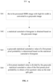
- FIG. 4 is a flow chart of S31 as shown in FIG. 3 according to an embodiment. Said determining the total split gain may include S41 to S44 which are described below.
- the to-be-processed HDR image with high bit width is converted to a grayscale image.
- a conventional grayscale image conversion technology may be used to convert the HDR image with high bit width into a grayscale image, and in the embodiments of the present disclosure, there is no limitation on a specific grayscale image conversion technology.
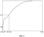
- FIG. 5 is a diagram of a cumulative histogram according to an embodiment.
- the input image may be converted into a grayscale image and the cumulative histogram may be counted, where a pixel probability distribution range [p0, p1] is preset as a to-be-counted area which is usually a low-brightness area and is subjected to highlight processing with a calculated gain subsequently.
- the cumulative histogram may be regarded as a function of gray level and used to represent the number of pixels with a certain gray level in the image, which reflects the frequency of certain gray levels in the image.
- FIG. 5 illustrates a maximum value bin_p1 and a minimum value bin_p0.
- a grayscale statistical cumulative value of a first preset pixel probability is determined based on the statistical cumulative histogram.
- the first preset pixel probability is a lower limit value of a first preset pixel probability range.
- the first preset pixel probability range may be the to-be-counted area [p0, p1], or other appropriate areas. Each area may be represented by a minimum probability (i.e., the lower limit value of the preset pixel probability range) and a maximum probability (i.e., the upper limit value of the preset pixel probability range).
- a first preset standard value is divided by the grayscale statistical cumulative value of the first preset pixel probability to obtain a first quotient value as the total split gain.
- the first preset pixel probability as the lower limit value of the first preset pixel probability range, a smaller total split gain may be obtained, so that the obtained HDR image with low bit width has a relatively small gain to prevent the image from being adjusted too bright, which is more suitable for bright scenes, such as daytime scenes.
- the total split gain may be determined based on an upper limit value of the first preset pixel probability range.
- FIG. 6 is a flow chart of S31 as shown in FIG. 3 according to an embodiment.
- Said determining the total split gain may include S61 to S64 which are described below.
- the to-be-processed HDR image with high bit width is converted to a grayscale image.
- the cumulative histogram may be referred to the cumulative histogram as shown in FIG. 5 .
- the input image may be converted into a grayscale image and the cumulative histogram may be counted, where a pixel probability distribution range [p0, p1] is preset as a to-be-counted area which is usually a low-brightness area and is subjected to highlight processing with a calculated gain subsequently.
- the cumulative histogram may be regarded as a function of gray level and used to represent the number of pixels with a certain gray level in the image, which reflects the frequency of certain gray levels in the image.
- FIG. 5 illustrates a maximum value bin_p1 and a minimum value bin_p0.
- a grayscale statistical cumulative value of a second preset pixel probability is determined based on the statistical cumulative histogram.
- the second preset pixel probability is an upper limit value of a second preset pixel probability range.
- the second preset pixel probability range may be the to-be-counted area [p0, p1], or other appropriate areas. Each area may be represented by a minimum probability (i.e., the lower limit value of the preset pixel probability range) and a maximum probability (i.e., the upper limit value of the preset pixel probability range).
- a second preset standard value is divided by the grayscale statistical cumulative value of the second preset pixel probability to obtain a second quotient value as the total split gain.
- the second preset pixel probability as the upper limit value of the second preset pixel probability range, a larger total split gain may be obtained, so that the obtained HDR image with low bit width has a relatively large gain to avoid the image being adjusted too dim, which is more suitable for dim scenes, such as night scenes.
- the total split gain may be determined based on an average value of a third preset pixel probability range.
- FIG. 7 is a flow chart of S31 as shown in FIG. 3 according to an embodiment.
- Said determining the total split gain may include S71 to S74 which are described below.
- the to-be-processed HDR image with high bit width is converted to a grayscale image.
- the cumulative histogram may be referred to the cumulative histogram as shown in FIG. 5 .
- the input image may be converted into a grayscale image and the cumulative histogram may be counted, where a pixel probability distribution range [p0, p1] is preset as a to-be-counted area which is usually a low-brightness area and is subjected to highlight processing with a calculated gain subsequently.
- the cumulative histogram may be regarded as a function of gray level and used to represent the number of pixels with a certain gray level in the image, which reflects the frequency of certain gray levels in the image.
- an average value bin_avg may be calculated based on the number of pixels between a maximum value bin_p1 and a minimum value bin_p0.
- an average value of grayscale statistical cumulative values within a third preset pixel probability range is determined based on the statistical cumulative histogram.
- the third preset pixel probability range may be the to-be-counted area [p0, p1], or other appropriate areas. Each area may be represented by a minimum probability (i.e., the lower limit value of the preset pixel probability range) and a maximum probability (i.e., the upper limit value of the preset pixel probability range), and an average value may be calculated based on the number of pixels between a maximum value and a minimum value.
- a preset average standard value is divided by the average value of the grayscale statistical cumulative values to obtain a third quotient value as the total split gain.
- a modest total split gain may be obtained, so that the obtained HDR image with low bit width has a modest gain to avoid the image being adjusted too bright or too dim, which is more suitable for routine scenes.
- a number N of split frames is determined based on a preset single frame gain and the total split gain.
- the first frame to an (N-1)th frame of split images are determined based on the preset single frame gain and the to-be-processed HDR image with high bit width.
- said determining the first frame to an (N-1)th frame of split images based on the preset single frame gain and the to-be-processed HDR image with high bit width includes: multiplying the to-be-processed HDR image with high bit width by (N-2) G_deltas to obtain the (N-1)th frame of split image, where G_delta is the preset single frame gain, and N ⁇ 2.
- following split images may be acquired.
- the first frame is the original frame, which is the HDR image with high bit width;
- the Nth frame of split image is determined based on at least the total split gain.
- said determining the Nth frame of split image based on at least the total split gain includes: determining that the Nth frame of split image is a product of the (N-1)th frame of split image and an N frame gain.
- the Nth frame is the (N-1)th frame ⁇ (G_total/(G_delta ⁇ (N-2))), where the N frame gain is G_total/(G_delta ⁇ (N-2)), G_total is the total split gain, and G_delta is the preset single frame gain.
- said determining the Nth frame of split image based on at least the total split gain includes: determining that the Nth frame of split image is a product of the to-be-processed HDR image with high bit width and the total split gain.
- the Nth frame is the original frame ⁇ G_total, where G_total is the total split gain.
- the number of frames N is determined, and the first (N-1) frames of split images and the Nth frame of split image can be determined in different ways.
- the (N-1) frames of split images respectively contain at least a portion of information of the to-be-processed HDR image with high bit width, and information amount of the (N-1) frames of split images may be different to form a transition.
- bit width reduction processing is performed on the first frame to the Nth frame of split images respectively, to obtain N frames of low-bit-width images.
- a conventional bit width reduction processing technique may be used, which is not limited in the embodiments of the present disclosure.
- said synthesizing the N frames of low-bit-width images to obtain the HDR image with low bit width includes: inputting the N frames of low-bit-width images into an ISP to output processed N frames of low-bit-width images; and performing fusion processing on the processed N frames of low-bit-width images to obtain the HDR image with low bit width.
- each split image is input into the ISP, and usually the image processed by and output from the ISP is a low-bit-width image that is displayable on a display device. Then the image signal processing unit outputs N frames of low-bit-width images with different brightness which are fused into one frame of HDR image with low bit width. More specifically, a multi-exposure image HDR synthesis method may be selected for fusion, which is not limited in the embodiments of the present disclosure.
- the to-be-processed HDR image with high bit width is split to obtain N frames of split images, and bit width reduction processing is performed on the N frames of split images respectively, to obtain N frames of low-bit-width images.
- bit width reduction processing is performed on the N frames of split images respectively, to obtain N frames of low-bit-width images.
- each frame of the low-bit-width image contains at least part of information of a numerical range of the to-be-processed HDR image with high bit width, which enables N frames of low-bit-width images to cover all information of the to-be-processed HDR image with high bit width. Therefore, when the bit width of data is reduced, a precision loss of graphics may be effectively reduced, and better image processing effect may be achieved.
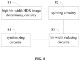
- FIG. 8 is a structural diagram of an apparatus for generating an HDR image with low bit width according to an embodiment.
- the apparatus includes a high-bit-width HDR image determining circuitry 81, a splitting circuitry 82, a bit width reducing circuitry 83 and a synthesizing circuitry 84.
- the high-bit-width HDR image determining circuitry 81 is configured to determine a to-be-processed HDR image with high bit width.
- the splitting circuitry 82 is configured to split the to-be-processed HDR image with high bit width to obtain N frames of split images which include a first frame to an Nth frame.
- the bit width reducing circuitry 83 is configured to perform bit width reduction processing on the N frames of split images respectively, to obtain N frames of low-bit-width images.
- the synthesizing circuitry 84 is configured to synthesize the N frames of low-bit-width images to obtain the HDR image with low bit width.
- the above apparatus may correspond to a chip with a data processing function in a UE, such as a baseband chip, or correspond to a chip module having a chip with a data processing function in a UE, or correspond to a UE.
- a storage medium having computer instructions stored therein wherein when the computer instructions are executed, the above method for generating an HDR image with low bit width is performed.
- the storage medium may be a computer readable storage medium, and may include a non-volatile or a non-transitory memory, or include an optical disk, a hard disk drive or a solid state disk.
- a terminal including a memory and a processor
- the memory has computer instructions stored therein, and when the processor executes the computer instructions, the above method for generating an HDR image with low bit width is performed.
- the terminal includes but is not limited to a mobile phone, a computer or a tablet computer.
- Modules/units included in each apparatus and product described in the above embodiments may be software modules/units, hardware modules/units, or a combination of software modules/units and hardware modules/units.
- each module/unit included therein may be implemented by hardware such as circuits; or, at least some modules/units may be implemented by a software program running on a processor integrated inside the chip, and the remaining (if any) part of the modules/units may be implemented by hardware such as circuits.
- each module/unit included therein may be implemented by hardware such as circuits.
- Different modules/units may be disposed in a same component (such as a chip or a circuit module) or in different components of the chip module. Or at least some modules/units may be implemented by a software program running on a processor integrated inside the chip module, and the remaining (if any) part of the modules/units may be implemented by hardware such as circuits. For each apparatus or product applied to or integrated in a terminal, each module/unit included therein may be implemented by hardware such as circuits. Different modules/units may be disposed in a same component (such as a chip or a circuit module) or in different components of the terminal. Or at least some modules/units may be implemented by a software program running on a processor integrated inside the terminal, and the remaining (if any) part of the modules/units may be implemented by hardware such as circuits.
Landscapes
- Engineering & Computer Science (AREA)
- Multimedia (AREA)
- Signal Processing (AREA)
- Physics & Mathematics (AREA)
- General Physics & Mathematics (AREA)
- Theoretical Computer Science (AREA)
- Computer Vision & Pattern Recognition (AREA)
- Image Processing (AREA)
- Studio Devices (AREA)
Description
- The present disclosure generally relates to communication technology field, and more particularly, to a method and apparatus for generating a High Dynamic Range (HDR) image with low bit width, a storage medium, and a terminal.
- An image signal processing apparatus receives raw data from an image sensor, processes the raw data, and outputs an image that is displayable on a screen. High dynamic range (HDR) images usually have higher bit width and contain more brightness and detail information. An HDR image may be acquired by synthesizing multiple frames of different exposure images into one frame of HDR image, or synthesizing multiple frames of equal exposure images into one frame of HDR image, or outputting from an image sensor with an HDR function. To preserve complete information of HDR data, a signal processing apparatus capable of receiving and processing high-bit-width images is required.
- A maximum bit width of images that can be processed by existing image processing systems and apparatuses is usually lower than that of HDR images. With the development of HDR technology, there are more and more applications of HDR image processing. To guarantee image accuracy, an image processing system that supports high bit width input is usually required. When a low-bit-width image processing system processes HDR images with high bit width, high-bit-width image data needs to be reduced in bit width in advance. Shifting or truncating high-bit-width data to reduce the bit width may cause a loss in a dynamic range of the image and thus affect image quality. If high-bit and low-bit information of the high-bit-width data are retained in low-bit-width data by nonlinear compression and input to the image processing system, a linear proportional relationship of original image data may also be destroyed. During processing of RAW image data, anomaly may be caused to image details and colors.
-
CN 105744157 A discloses an image pixel sampling value conversion method and device as well as a sampling value processing method and device, which are used for converting a high-bit depth pixel sampling value into a low-bit depth sampling value. The image pixel sampling value conversion method comprises the steps of dividing a value range of the high-bit depth pixel sampling value into one or more segments and determining metadata of segment endpoints, wherein the metadata comprise high-bit depth pixel sampling values of the segment endpoints and corresponding low-bit depth sampling values; determining segments which the high-bit depth pixel sampling values in an image belongs to according to the metadata; and calculating the low-bit depth sampling values corresponding to the high-bit depth pixel sampling values based on the metadata of the segment endpoints. -
CN 106851138 B discloses an image processing method based on an HDR. The method comprises the steps of obtaining high-bit-wide image data collected by image collection equipment; conducting bit interception operation on each frame of high-bit-wide image of the image data according to a set sequence to generate at least three low-bit-wide images with a set amount of bit data and different brightness; obtaining image quality parameters of each image, and calculating corresponding fusion weight factors; performing downsampling processing on pixel values and the fusion weight factors of the pixel values, and conducting weight fusion on images in the same downsampling dimension; performing downsampling reverse operation on a weight fusion result to generate a frame of low-bit-wide high dynamic range image. -
CN 105827971 A discloses an image processing method and a mobile terminal. The image processing method comprises the following steps: obtaining multiple frames of an original image, continuously acquired by a pick-up head; performing synthesis processing on the multiple frames of the original image through a preset algorithm to obtain a first intermediate image; performing image processing on the first intermediate image to obtain a second intermediate image; and performing image compression processing on the second intermediate image to obtain a final image, wherein the multiple frames of the original image and the first intermediate image are 10-bit-wide images in a Raw format, the second intermediate image is an 8-bit-wide image in a YUV format, and the final image is an 8-bit-wide image in a JPEG format. - In conclusion, there is an urgent need for a method for generating an HDR image with low bit width, which may effectively reduce a precision loss of graphics and achieve better image processing effect while reducing bit width of data.
- The invention is set out in the appended set of claims.
- A method and apparatus for generating an HDR image with low bit width, a storage medium, and a terminal are provided, which may effectively reduce a precision loss of graphics and achieve better image processing effect while reducing bit width of data.
- A method for generating an HDR image with low bit width is provided, including: determining a to-be-processed HDR image with high bit width; splitting the to-be-processed HDR image with high bit width to obtain N frames of split images which include a first frame to an Nth frame; performing bit width reduction processing on the N frames of split images respectively, to obtain N frames of low-bit-width images; and synthesizing the N frames of low-bit-width images to obtain the HDR image with low bit width.
- Said splitting the to-be-processed HDR image with high bit width includes: determining a total split gain; determining a number N of split frames based on a preset single frame gain and the total split gain; determining the first frame to an (N-1)th frame of split images based on the preset single frame gain and the to-be-processed HDR image with high bit width; and determining the Nth frame of split image based on at least the total split gain.
- Optionally, said determining a total split gain includes: converting the to-be-processed HDR image with high bit width to a grayscale image; obtaining a statistical cumulative histogram based on the grayscale image; determining a grayscale statistical cumulative value of a first preset pixel probability based on the statistical cumulative histogram; and dividing a first preset standard value by the grayscale statistical cumulative value of the first preset pixel probability to obtain a first quotient value as the total split gain.
- Optionally, the first preset pixel probability is a lower limit value of a first preset pixel probability range.
- Optionally, said determining a total split gain includes: converting the to-be-processed HDR image with high bit width to a grayscale image; obtaining a statistical cumulative histogram based on the grayscale image; determining a grayscale statistical cumulative value of a second preset pixel probability based on the statistical cumulative histogram; and dividing a second preset standard value by the grayscale statistical cumulative value of the second preset pixel probability to obtain a second quotient value as the total split gain.
- Optionally, the second preset pixel probability is an upper limit value of a second preset pixel probability range.
- Optionally, said determining a total split gain includes: converting the to-be-processed HDR image with high bit width to a grayscale image; obtaining a statistical cumulative histogram based on the grayscale image; determining an average value of grayscale statistical cumulative values within a third preset pixel probability range based on the statistical cumulative histogram; and dividing a preset average standard value by the average value of the grayscale statistical cumulative values to obtain a third quotient value as the total split gain.
- Optionally, the number N of split frames is determined based on the preset single frame gain and the total split gain by using a following formula:

- Optionally, said determining the first frame to an (N-1)th frame of split images based on the preset single frame gain and the to-be-processed HDR image with high bit width includes: multiplying the to-be-processed HDR image with high bit width by (N-2) G_deltas to obtain the (N-1)th frame of split image, where G_delta is the preset single frame gain, and N≥2.
- Optionally, said determining the Nth frame of split image based on at least the total split gain includes: determining that the Nth frame of split image is a product of the (N-1)th frame of split image and an N frame gain, where the N frame gain is G_total/(G_delta^(N-2)), G_total is the total split gain, and G_delta is the preset single frame gain.
- Optionally, said determining the Nth frame of split image based on at least the total split gain includes: determining that the Nth frame of split image is a product of the to-be-processed HDR image with high bit width and the total split gain.
- Optionally, said synthesizing the N frames of low-bit-width images to obtain the HDR image with low bit width includes: inputting the N frames of low-bit-width images into an Image Signal Processor (ISP) to output processed N frames of low-bit-width images; and performing fusion processing on the processed N frames of low-bit-width images to obtain the HDR image with low bit width.
- In an embodiment of the present disclosure, an apparatus for generating an HDR image with low bit width is provided, including: a high-bit-width HDR image determining circuitry configured to determine a to-be-processed HDR image with high bit width; a splitting circuitry configured to split the to-be-processed HDR image with high bit width to obtain N frames of split images which include a first frame to an Nth frame; a bit width reducing circuitry configured to perform bit width reduction processing on the N frames of split images respectively, to obtain N frames of low-bit-width images; and a synthesizing circuitry configured to synthesize the N frames of low-bit-width images to obtain the HDR image with low bit width.
- A storage medium having computer instructions stored therein is provided, wherein when the computer instructions are executed, the above method for generating an HDR image with low bit width is performed.
- A terminal including a memory and a processor is provided, wherein the memory has computer instructions stored therein, and when the processor executes the computer instructions, the above method for generating an HDR image with low bit width is performed.
- Embodiments of the present disclosure may provide following advantages.
- In embodiments of the present disclosure, the to-be-processed HDR image with high bit width is split to obtain N frames of split images, and bit width reduction processing is performed on the N frames of split images respectively, to obtain N frames of low-bit-width images. Compared with the exiting techniques where image anomaly is caused by retaining high-bit and low-bit information of a high-bit-width HDR image in low-bit-width data by nonlinear compression, in embodiments of the present disclosure, after the to-be-processed HDR image with high bit width is split into N frames of split images, each frame of the low-bit-width image contains at least part of information of a numerical range of the to-be-processed HDR image with high bit width, which enables N frames of low-bit-width images to cover all information of the to-be-processed HDR image with high bit width. Therefore, when the bit width of data is reduced, a precision loss of graphics may be effectively reduced, and better image processing effect may be achieved.
- Further, in embodiments of the present disclosure, by determining the total split gain and pre-setting the single frame gain, the number of frames N is determined, and the first (N-1) frames of split images and the Nth frame of split image can be determined in different ways. In this manner, the (N-1) frames of split images respectively contain at least a portion of information of the to-be-processed HDR image with high bit width, and information amount of the (N-1) frames of split images may be different to form a transition. Further, there is an opportunity to set the Nth frame of split image to avoid the image to be affected merely by the single frame gain, thereby further improving image processing effect by setting multiple parameters.
- Further, in embodiments of the present disclosure, by setting the first preset pixel probability as the lower limit value of the first preset pixel probability range, a smaller total split gain may be obtained, so that the obtained HDR image with low bit width has a relatively small gain to prevent the image from being adjusted too bright, which is more suitable for bright scenes, such as daytime scenes.
- Further, in embodiments of the present disclosure, by setting the second preset pixel probability as the upper limit value of the second preset pixel probability range, a larger total split gain may be obtained, so that the obtained HDR image with low bit width has a relatively large gain to avoid the image being adjusted too dim, which is more suitable for dim scenes, such as night scenes.
-
-
FIG. 1 is a structural diagram of an image processing unit in existing techniques; -
FIG. 2 is a flow chart of a method for generating an HDR image with low bit width according to an embodiment; -
FIG. 3 is a flow chart of S21 as shown inFIG. 2 according to an embodiment; -
FIG. 4 is a flow chart of S31 as shown inFIG. 3 according to an embodiment; -
FIG. 5 is a diagram of a cumulative histogram according to an embodiment; -
FIG. 6 is a flow chart of S31 as shown inFIG. 3 according to an embodiment; -
FIG. 7 is a flow chart of S31 as shown inFIG. 3 according to an embodiment; and -
FIG. 8 is a structural diagram of an apparatus for generating an HDR image with low bit width according to an embodiment. - As described in the background, to preserve complete information of HDR data, a signal processing apparatus capable of receiving and processing high-bit-width images is required. A maximum bit width of images that can be processed by existing image processing systems and apparatuses is usually lower than that of HDR images. With the development of HDR technology, there are more and more applications of HDR image processing. To guarantee image accuracy, an image processing system that supports high bit width input is usually required.
- Referring to
FIG. 1, FIG. 1 is a structural diagram of an image processing unit in existing techniques. Animage processing unit 12 is configured to receive an original image from an originalimage input unit 11, and output the processed original image to astorage unit 13. - Specifically, the
image processing unit 12 may include an original image processing sub-unit, a color image processing sub-unit, and an image post-processing sub-unit, and may also include other appropriate modules, which are not described in detail here. - In specific implementation, an image processing process for photographing by a general mobile phone camera is shown in
FIG. 1 . For example, an image sensor is used to output an image in a Bayer raw format to theimage processing unit 12. The image is then subjected to a series of processing, output and saved as an image that is displayable on a display device. - Inventors found based on researches that in existing techniques, multiple frames of low-bit-width images with different exposures are shot for a same scene, and are processed by and then output from the
image processing unit 12. The output multiple frames of images are synthesized through multiple exposures to directly generate an HDR image with low bit width. When shooting dynamic scenes, camera displacement and object motion inevitably cause image blur and ghosting of moving objects. It is necessary to perform alignment and ghost removal operations during fusion to ensure better image quality, thereby increasing complexity of the fusion. When the number of frames is great, it is difficult to meet requirements of real-time HDR photography. - The inventors found based on further researches that some current HDR technologies can complete alignment and ghost removal operations at the same time as HDR image generation, which makes alignment and ghost removal easier. Some image sensors with an HDR function can also output ghost-free HDR raw data. However, processing of these HDR raw data always requires a specially designed high-bit-width image processing apparatus, and the HDR raw data is then converted into a low-bit image that is displayable on a display device after dynamic range compression, which limits application of the existing low-bit-width image processing system.
- In a specific example, the existing image signal processing system receives 10-bit raw data, and performs bit-width reduction processing on data with a 12-bit or higher bit width, which easily results in a loss in precision of multiple bits and poor image processing effect.
- A to-be-processed HDR image with high bit width is determined and split to obtain N frames of split images which include a first frame to an Nth frame, bit width reduction processing is performed on the N frames of split images respectively to obtain N frames of low-bit-width images, and the N frames of low-bit-width images are synthesized to obtain the HDR image with low bit width. The to-be-processed HDR image with high bit width is split to obtain N frames of split images, and bit width reduction processing is performed on the N frames of split images respectively, to obtain N frames of low-bit-width images. Compared with the existing techniques where image anomaly is caused by retaining high-bit and low-bit information of a high-bit-width HDR image in low-bit-width data by nonlinear compression after the to-be-processed HDR image with high bit width is split into N frames of split images, each frame of the low-bit-width image contains at least part of information of a numerical range of the to-be-processed HDR image with high bit width, which enables N frames of low-bit-width images to cover all information of the to-be-processed HDR image with high bit width. Therefore, when the bit width of data is reduced, a precision loss of graphics may be effectively reduced, and better image processing effect may be achieved.
- In order to clarify the objects, characteristics and advantages of the disclosure, embodiments of present disclosure will be described in detail in conjunction with accompanying drawings.
-
FIG. 2 is a flow chart of a method for generating an HDR image with low bit width. Referring toFIG. 2 , the method includes S21 to S24. - In S21, a to-be-processed HDR image with high bit width is determined.
- In S22, the to-be-processed HDR image with high bit width is split to obtain N frames of split images which include a first frame to an Nth frame.
- In S23, bit width reduction processing is performed on the N frames of split images respectively, to obtain N frames of low-bit-width images.
- In S24, the N frames of low-bit-width images are synthesized to obtain the HDR image with low bit width.
- The method is implemented in a form of a software program which runs in a processor integrated inside a chip or a chip module.
- In some embodiments, in S21, an HDR RAW image with high bit width may be input, where the bit width is higher than that processed by an existing ISP system. That is, when data bit width processed by the existing ISP system is 10 bits, the data bit width of the input image may be 12, 14, 16, 20, 24 bits, etc.
- In S22, the to-be-processed HDR image with high bit width is split to obtain N frames of split images.
-
FIG. 3 is a flow chart of S22 as shown inFIG. 2 according to an embodiment. Said splitting the to-be-processed HDR image with high bit width may include S31 to S34 which are described below. - In S31, a total split gain is determined.
- In some embodiments, to better retain both high-brightness details and low-brightness details of the original image in the split images, a brightness gain that needs to be improved in the low-brightness part of the image may be estimated according to a pixel value distribution of the originally input image.
- In some embodiments, the total split gain may be determined based on a lower limit value of the first preset pixel probability range.
-
FIG. 4 is a flow chart of S31 as shown inFIG. 3 according to an embodiment. Said determining the total split gain may include S41 to S44 which are described below. - In S41, the to-be-processed HDR image with high bit width is converted to a grayscale image.
- Specifically, a conventional grayscale image conversion technology may be used to convert the HDR image with high bit width into a grayscale image, and in the embodiments of the present disclosure, there is no limitation on a specific grayscale image conversion technology.
- In S42, a statistical cumulative histogram is obtained based on the grayscale image.
- Referring to
FIG. 5, FIG. 5 is a diagram of a cumulative histogram according to an embodiment. - Specifically, the input image may be converted into a grayscale image and the cumulative histogram may be counted, where a pixel probability distribution range [p0, p1] is preset as a to-be-counted area which is usually a low-brightness area and is subjected to highlight processing with a calculated gain subsequently.
- The cumulative histogram may be regarded as a function of gray level and used to represent the number of pixels with a certain gray level in the image, which reflects the frequency of certain gray levels in the image.
FIG. 5 illustrates a maximum value bin_p1 and a minimum value bin_p0. - It should be noted that a conventional statistical technique may be used to count the cumulative histogram of the grayscale image, which is not limited in the embodiments of the present disclosure.
- In S43, a grayscale statistical cumulative value of a first preset pixel probability is determined based on the statistical cumulative histogram.
- Further, the first preset pixel probability is a lower limit value of a first preset pixel probability range.
- The first preset pixel probability range may be the to-be-counted area [p0, p1], or other appropriate areas. Each area may be represented by a minimum probability (i.e., the lower limit value of the preset pixel probability range) and a maximum probability (i.e., the upper limit value of the preset pixel probability range).
- In S44, a first preset standard value is divided by the grayscale statistical cumulative value of the first preset pixel probability to obtain a first quotient value as the total split gain.
- Specifically, the first preset standard value may be divided by the lower limit value of the first preset pixel probability range to obtain a first quotient value as the total split gain:

- In the embodiments, by setting the first preset standard value, it is beneficial to adjust the total split gain in time by adjusting the first standard value according to actual situations.
- In embodiments of the present disclosure, by setting the first preset pixel probability as the lower limit value of the first preset pixel probability range, a smaller total split gain may be obtained, so that the obtained HDR image with low bit width has a relatively small gain to prevent the image from being adjusted too bright, which is more suitable for bright scenes, such as daytime scenes.
- Referring to
FIG. 3 , in some embodiments, in S31, the total split gain may be determined based on an upper limit value of the first preset pixel probability range. -
FIG. 6 is a flow chart of S31 as shown inFIG. 3 according to an embodiment. Said determining the total split gain may include S61 to S64 which are described below. - In S61, the to-be-processed HDR image with high bit width is converted to a grayscale image.
- In S62, a statistical cumulative histogram is obtained based on the grayscale image.
- Specifically, the cumulative histogram may be referred to the cumulative histogram as shown in
FIG. 5 . - Specifically, the input image may be converted into a grayscale image and the cumulative histogram may be counted, where a pixel probability distribution range [p0, p1] is preset as a to-be-counted area which is usually a low-brightness area and is subjected to highlight processing with a calculated gain subsequently.
- The cumulative histogram may be regarded as a function of gray level and used to represent the number of pixels with a certain gray level in the image, which reflects the frequency of certain gray levels in the image.
FIG. 5 illustrates a maximum value bin_p1 and a minimum value bin_p0. - In S63, a grayscale statistical cumulative value of a second preset pixel probability is determined based on the statistical cumulative histogram.
- Further, the second preset pixel probability is an upper limit value of a second preset pixel probability range.
- The second preset pixel probability range may be the to-be-counted area [p0, p1], or other appropriate areas. Each area may be represented by a minimum probability (i.e., the lower limit value of the preset pixel probability range) and a maximum probability (i.e., the upper limit value of the preset pixel probability range).
- In S64, a second preset standard value is divided by the grayscale statistical cumulative value of the second preset pixel probability to obtain a second quotient value as the total split gain.
- Specifically, the second preset standard value may be divided by the upper limit value of the second preset pixel probability range to obtain a second quotient value as the total split gain:

bin_p 1 is the upper limit value of the second preset pixel probability range. - In the embodiments, by setting the second preset standard value, it is beneficial to adjust the total split gain in time by adjusting the second standard value according to actual situations.
- In embodiments of the present disclosure, by setting the second preset pixel probability as the upper limit value of the second preset pixel probability range, a larger total split gain may be obtained, so that the obtained HDR image with low bit width has a relatively large gain to avoid the image being adjusted too dim, which is more suitable for dim scenes, such as night scenes.
- Referring to
FIG. 3 , in some embodiments, in S31, the total split gain may be determined based on an average value of a third preset pixel probability range. -
FIG. 7 is a flow chart of S31 as shown inFIG. 3 according to an embodiment. Said determining the total split gain may include S71 to S74 which are described below. - In S71, the to-be-processed HDR image with high bit width is converted to a grayscale image.
- In S72, a statistical cumulative histogram is obtained based on the grayscale image.
- Specifically, the cumulative histogram may be referred to the cumulative histogram as shown in
FIG. 5 . - Specifically, the input image may be converted into a grayscale image and the cumulative histogram may be counted, where a pixel probability distribution range [p0, p1] is preset as a to-be-counted area which is usually a low-brightness area and is subjected to highlight processing with a calculated gain subsequently.
- The cumulative histogram may be regarded as a function of gray level and used to represent the number of pixels with a certain gray level in the image, which reflects the frequency of certain gray levels in the image. For example, in
FIG. 5 , an average value bin_avg may be calculated based on the number of pixels between a maximum value bin_p1 and a minimum value bin_p0. - In S73, an average value of grayscale statistical cumulative values within a third preset pixel probability range is determined based on the statistical cumulative histogram.
- The third preset pixel probability range may be the to-be-counted area [p0, p1], or other appropriate areas. Each area may be represented by a minimum probability (i.e., the lower limit value of the preset pixel probability range) and a maximum probability (i.e., the upper limit value of the preset pixel probability range), and an average value may be calculated based on the number of pixels between a maximum value and a minimum value.
- In S74, a preset average standard value is divided by the average value of the grayscale statistical cumulative values to obtain a third quotient value as the total split gain.
- Specifically, the preset average standard value is divided by the average value of the grayscale statistical cumulative values to obtain a third quotient value as the total split gain:

- In the embodiments, by setting the preset average standard value, it is beneficial to adjust the total split gain in time by adjusting the average standard value according to actual situations.
- In embodiments of the present disclosure, by setting the average value of grayscale statistical cumulative values within the third preset pixel probability range, a modest total split gain may be obtained, so that the obtained HDR image with low bit width has a modest gain to avoid the image being adjusted too bright or too dim, which is more suitable for routine scenes.
- Referring to
FIG. 3 , in S32, a number N of split frames is determined based on a preset single frame gain and the total split gain. - Specifically, the number N of split frames is determined based on the preset single frame gain and the total split gain by using a following formula:

- In S33, the first frame to an (N-1)th frame of split images are determined based on the preset single frame gain and the to-be-processed HDR image with high bit width.
- In some embodiments, said determining the first frame to an (N-1)th frame of split images based on the preset single frame gain and the to-be-processed HDR image with high bit width includes: multiplying the to-be-processed HDR image with high bit width by (N-2) G_deltas to obtain the (N-1)th frame of split image, where G_delta is the preset single frame gain, and N≥2.
- In some embodiments, following split images may be acquired.
- The first frame is the original frame, which is the HDR image with high bit width;
- the second frame is the first frame × G delta;
- the third frame is the second frame × G delta;
... and - the (N-1)th frame is the (N-2)th frame × G_delta.
- In S34, the Nth frame of split image is determined based on at least the total split gain.
- In some embodiments, said determining the Nth frame of split image based on at least the total split gain includes: determining that the Nth frame of split image is a product of the (N-1)th frame of split image and an N frame gain.
- That is, the Nth frame is the (N-1)th frame × (G_total/(G_delta^(N-2))), where the N frame gain is G_total/(G_delta^(N-2)), G_total is the total split gain, and G_delta is the preset single frame gain.
- In some embodiments, said determining the Nth frame of split image based on at least the total split gain includes: determining that the Nth frame of split image is a product of the to-be-processed HDR image with high bit width and the total split gain.
- That is, the Nth frame is the original frame × G_total, where G_total is the total split gain.
- In the embodiments of the present disclosure, by determining the total split gain and pre-setting the single frame gain, the number of frames N is determined, and the first (N-1) frames of split images and the Nth frame of split image can be determined in different ways. In this manner, the (N-1) frames of split images respectively contain at least a portion of information of the to-be-processed HDR image with high bit width, and information amount of the (N-1) frames of split images may be different to form a transition. Further, there is an opportunity to set the Nth frame of split image to avoid the image to be affected merely by the single frame gain, thereby further improving image processing effect by setting multiple parameters.
- Referring to
FIG. 2 , in some embodiments, in S23, bit width reduction processing is performed on the first frame to the Nth frame of split images respectively, to obtain N frames of low-bit-width images. - In some embodiments, a conventional bit width reduction processing technique may be used, which is not limited in the embodiments of the present disclosure.
- In some embodiments, in S24, said synthesizing the N frames of low-bit-width images to obtain the HDR image with low bit width includes: inputting the N frames of low-bit-width images into an ISP to output processed N frames of low-bit-width images; and performing fusion processing on the processed N frames of low-bit-width images to obtain the HDR image with low bit width.
- Specifically, each split image is input into the ISP, and usually the image processed by and output from the ISP is a low-bit-width image that is displayable on a display device. Then the image signal processing unit outputs N frames of low-bit-width images with different brightness which are fused into one frame of HDR image with low bit width. More specifically, a multi-exposure image HDR synthesis method may be selected for fusion, which is not limited in the embodiments of the present disclosure.
- In embodiments of the present disclosure, the to-be-processed HDR image with high bit width is split to obtain N frames of split images, and bit width reduction processing is performed on the N frames of split images respectively, to obtain N frames of low-bit-width images. Compared with the exiting techniques where image anomaly is caused by retaining high-bit and low-bit information of a high-bit-width HDR image in low-bit-width data by nonlinear compression, in embodiments of the present disclosure, after the to-be-processed HDR image with high bit width is split into N frames of split images, each frame of the low-bit-width image contains at least part of information of a numerical range of the to-be-processed HDR image with high bit width, which enables N frames of low-bit-width images to cover all information of the to-be-processed HDR image with high bit width. Therefore, when the bit width of data is reduced, a precision loss of graphics may be effectively reduced, and better image processing effect may be achieved.
- Referring to
FIG. 8, FIG. 8 is a structural diagram of an apparatus for generating an HDR image with low bit width according to an embodiment. The apparatus includes a high-bit-width HDRimage determining circuitry 81, a splittingcircuitry 82, a bitwidth reducing circuitry 83 and a synthesizingcircuitry 84. - The high-bit-width HDR
image determining circuitry 81 is configured to determine a to-be-processed HDR image with high bit width. - The splitting
circuitry 82 is configured to split the to-be-processed HDR image with high bit width to obtain N frames of split images which include a first frame to an Nth frame. - The bit
width reducing circuitry 83 is configured to perform bit width reduction processing on the N frames of split images respectively, to obtain N frames of low-bit-width images. - The synthesizing
circuitry 84 is configured to synthesize the N frames of low-bit-width images to obtain the HDR image with low bit width. - In some embodiments, the above apparatus may correspond to a chip with a data processing function in a UE, such as a baseband chip, or correspond to a chip module having a chip with a data processing function in a UE, or correspond to a UE.
- More details on principles, implementations and advantages of the apparatus may be referred to relevant descriptions of the method as mentioned above and illustrated in
FIGS. 2 to 7 , which are not repeated here. - In an embodiment of the present disclosure, a storage medium having computer instructions stored therein is provided, wherein when the computer instructions are executed, the above method for generating an HDR image with low bit width is performed. In some embodiments, the storage medium may be a computer readable storage medium, and may include a non-volatile or a non-transitory memory, or include an optical disk, a hard disk drive or a solid state disk.
- In an embodiment of the present disclosure, a terminal including a memory and a processor is provided, wherein the memory has computer instructions stored therein, and when the processor executes the computer instructions, the above method for generating an HDR image with low bit width is performed. The terminal includes but is not limited to a mobile phone, a computer or a tablet computer.
- Modules/units included in each apparatus and product described in the above embodiments may be software modules/units, hardware modules/units, or a combination of software modules/units and hardware modules/units. For example, for each apparatus or product applied to or integrated in a chip, each module/unit included therein may be implemented by hardware such as circuits; or, at least some modules/units may be implemented by a software program running on a processor integrated inside the chip, and the remaining (if any) part of the modules/units may be implemented by hardware such as circuits. For each apparatus or product applied to or integrated in a chip module, each module/unit included therein may be implemented by hardware such as circuits. Different modules/units may be disposed in a same component (such as a chip or a circuit module) or in different components of the chip module. Or at least some modules/units may be implemented by a software program running on a processor integrated inside the chip module, and the remaining (if any) part of the modules/units may be implemented by hardware such as circuits. For each apparatus or product applied to or integrated in a terminal, each module/unit included therein may be implemented by hardware such as circuits. Different modules/units may be disposed in a same component (such as a chip or a circuit module) or in different components of the terminal. Or at least some modules/units may be implemented by a software program running on a processor integrated inside the terminal, and the remaining (if any) part of the modules/units may be implemented by hardware such as circuits.
- Although the present disclosure has been disclosed above with reference to preferred embodiments thereof, it should be understood that the disclosure is presented by way of example only, and not limitation. Those skilled in the art can modify and vary the embodiments of the present disclosure
Claims (13)
- A method for generating a High Dynamic Range (HDR) image with low bit width, comprising:determining (S21) a to-be-processed HDR image with high bit width;characterized in that the method further comprises:splitting (S22) the to-be-processed HDR image with high bit width to obtain N frames of split images which comprise a first frame to an Nth frame, wherein said splitting (S22) the to-be-processed HDR image with high bit width comprises: determining (S31) a total split gain, wherein the total split gain is a total gain of the N frames of split images; determining (S32) a number N of split frames based on a preset single frame gain and the total split gain, wherein the preset single frame gain is a preset gain of each of the N frames of split images; determining (S33) the first frame to an (N-1)th frame of split images based on the preset single frame gain and the to-be-processed HDR image with high bit width; and determining (S34) the Nth frame of split image based on at least the total split gain;performing (S23) bit width reduction processing on the N frames of split images respectively, to obtain N frames of low-bit-width images; andsynthesizing (S24) the N frames of low-bit-width images to obtain the HDR image with low bit width.
- The method according to claim 1, wherein said determining a total split gain comprises:converting (S41) the to-be-processed HDR image with high bit width to a grayscale image;obtaining (S42) a statistical cumulative histogram based on the grayscale image;determining (S43) a grayscale statistical cumulative value of a first preset pixel probability based on the statistical cumulative histogram; anddividing (S44) a first preset standard value by the grayscale statistical cumulative value of the first preset pixel probability to obtain a first quotient value as the total split gain.
- The method according to claim 2, wherein the first preset pixel probability is a lower limit value of a first preset pixel probability range.
- The method according to claim 1, wherein said determining a total split gain comprises:converting (S61) the to-be-processed HDR image with high bit width to a grayscale image;obtaining (S62) a statistical cumulative histogram based on the grayscale image;determining (S63) a grayscale statistical cumulative value of a second preset pixel probability based on the statistical cumulative histogram; anddividing (S64) a second preset standard value by the grayscale statistical cumulative value of the second preset pixel probability to obtain a second quotient value as the total split gain.
- The method according to claim 4, wherein the second preset pixel probability is an upper limit value of a second preset pixel probability range.
- The method according to claim 1, wherein said determining a total split gain comprises:converting (S71) the to-be-processed HDR image with high bit width to a grayscale image;obtaining (S72) a statistical cumulative histogram based on the grayscale image;determining (S73) an average value of grayscale statistical cumulative values within a third preset pixel probability range based on the statistical cumulative histogram; anddividing (S74) a preset average standard value by the average value of the grayscale statistical cumulative values to obtain a third quotient value as the total split gain.
- The method according to claim 1, wherein the number N of split frames is determined based on the preset single frame gain and the total split gain by using a following formula:

- The method according to claim 1, wherein said determining the first frame to an (N-1)th frame of split images based on the preset single frame gain and the to-be-processed HDR image with high bit width comprises:multiplying the to-be-processed HDR image with high bit width by (N-2) G_deltas to obtain the (N-1)th frame of split image,where G_delta is the preset single frame gain, and N≥2.
- The method according to claim 1, wherein said determining the Nth frame of split image based on at least the total split gain comprises:determining that the Nth frame of split image is a product of the (N-1)th frame of split image and an N frame gain,where the N frame gain is G_total/(G_delta^(N-2)), G_total is the total split gain, and G_delta is the preset single frame gain.
- The method according to claim 1, wherein said determining the Nth frame of split image based on at least the total split gain comprises:determining that the Nth frame of split image is a product of the to-be-processed HDR image with high bit width and the total split gain.
- The method according to claim 1, wherein said synthesizing the N frames of low-bit-width images to obtain the HDR image with low bit width comprises:inputting the N frames of low-bit-width images into an Image Signal Processor (ISP) to output processed N frames of low-bit-width images; andperforming fusion processing on the processed N frames of low-bit-width images to obtain the HDR image with low bit width.
- A storage medium having computer instructions stored therein, characterized in that when the computer instructions are executed, the method of any one of claims 1 to 11 is performed.
- A terminal comprising a memory and a processor, characterized in that the memory has computer instructions stored therein, and when the processor executes the computer instructions, the method of any one of claims 1 to 11 is performed.
Applications Claiming Priority (2)
| Application Number | Priority Date | Filing Date | Title |
|---|---|---|---|
| CN202010071654.9A CN111292282B (en) | 2020-01-21 | 2020-01-21 | Method and device for generating low-bit-width HDR images, storage medium, and terminal |
| PCT/CN2021/081721 WO2021148057A1 (en) | 2020-01-21 | 2021-03-19 | Method and apparatus for generating low bit width hdr image, storage medium, and terminal |
Publications (3)
| Publication Number | Publication Date |
|---|---|
| EP4095793A1 EP4095793A1 (en) | 2022-11-30 |
| EP4095793A4 EP4095793A4 (en) | 2023-10-25 |
| EP4095793B1 true EP4095793B1 (en) | 2024-12-11 |
Family
ID=71026680
Family Applications (1)
| Application Number | Title | Priority Date | Filing Date |
|---|---|---|---|
| EP21744134.4A Active EP4095793B1 (en) | 2020-01-21 | 2021-03-19 | Method and apparatus for generating low bit width hdr image, storage medium, and terminal |
Country Status (4)
| Country | Link |
|---|---|
| US (1) | US12231779B2 (en) |
| EP (1) | EP4095793B1 (en) |
| CN (1) | CN111292282B (en) |
| WO (1) | WO2021148057A1 (en) |
Families Citing this family (9)
| Publication number | Priority date | Publication date | Assignee | Title |
|---|---|---|---|---|
| CN111292282B (en) | 2020-01-21 | 2023-02-17 | 展讯通信(上海)有限公司 | Method and device for generating low-bit-width HDR images, storage medium, and terminal |
| CN111885312B (en) * | 2020-07-27 | 2021-07-09 | 展讯通信(上海)有限公司 | HDR image imaging method, system, electronic device and storage medium |
| US11736804B2 (en) * | 2020-09-07 | 2023-08-22 | Mediatek Inc. | Method and apparatus for generating high dynamic range frame through white balance compensation that uses white balance gain table generated from combining multiple sets of white balance gain settings |
| CN113409219B (en) * | 2021-06-28 | 2022-11-25 | 展讯通信(上海)有限公司 | Method and device for improving HDR image quality |
| WO2023015422A1 (en) * | 2021-08-09 | 2023-02-16 | 北京小米移动软件有限公司 | Image processing method and apparatus |
| US11587213B1 (en) * | 2021-11-05 | 2023-02-21 | GM Cruise Holdings LLC. | Preserving dynamic range in images |
| CN116416168A (en) * | 2021-12-28 | 2023-07-11 | 北京小米移动软件有限公司 | Image processing method, device, electronic device and storage medium |
| KR102938291B1 (en) * | 2022-07-06 | 2026-03-12 | 주식회사 엘엑스세미콘 | Logo detection module, timing controller including the same and method for driving the same |
| CN118714333B (en) * | 2024-08-27 | 2024-11-19 | 四川赛狄信息技术股份公司 | Image bit width conversion method and device based on histogram statistics |
Family Cites Families (12)
| Publication number | Priority date | Publication date | Assignee | Title |
|---|---|---|---|---|
| CN102186020A (en) | 2010-01-13 | 2011-09-14 | 株式会社尼康 | Image processing apparatus and image processing method |
| CN103325098A (en) * | 2013-07-02 | 2013-09-25 | 南京理工大学 | High dynamic infrared image enhancement method based on multi-scale processing |
| CN104639845B (en) * | 2015-03-17 | 2017-12-26 | 上海兆芯集成电路有限公司 | High dynamic range images production method and the device using this method |
| CN105513029B (en) | 2015-11-26 | 2018-06-08 | 天津津航技术物理研究所 | A kind of two-part thermal infrared imager auto gain control method |
| CN105744157A (en) * | 2016-02-02 | 2016-07-06 | 西安电子科技大学 | Image pixel sampling value conversion method and device as well as sampling value processing method and device |
| CN105827971B (en) * | 2016-03-31 | 2019-01-11 | 维沃移动通信有限公司 | A kind of image processing method and mobile terminal |
| CN106851138B (en) * | 2017-04-11 | 2019-07-16 | 成都聚像光学技术有限公司 | A kind of image processing method based on HDR |
| US20190313005A1 (en) * | 2018-04-05 | 2019-10-10 | Qualcomm Incorporated | Tone mapping for high-dynamic-range images |
| CN110049332A (en) | 2019-04-11 | 2019-07-23 | 深圳市朗驰欣创科技股份有限公司 | A kind of image compression method, image compression device and electronic equipment |
| CN111292282B (en) * | 2020-01-21 | 2023-02-17 | 展讯通信(上海)有限公司 | Method and device for generating low-bit-width HDR images, storage medium, and terminal |
| CN111479072B (en) * | 2020-04-14 | 2021-12-17 | 深圳市道通智能航空技术股份有限公司 | High dynamic range image synthesis method and device, image processing chip and aerial camera |
| US11736804B2 (en) * | 2020-09-07 | 2023-08-22 | Mediatek Inc. | Method and apparatus for generating high dynamic range frame through white balance compensation that uses white balance gain table generated from combining multiple sets of white balance gain settings |
-
2020
- 2020-01-21 CN CN202010071654.9A patent/CN111292282B/en active Active
-
2021
- 2021-03-19 US US17/794,409 patent/US12231779B2/en active Active
- 2021-03-19 EP EP21744134.4A patent/EP4095793B1/en active Active
- 2021-03-19 WO PCT/CN2021/081721 patent/WO2021148057A1/en not_active Ceased
Also Published As
| Publication number | Publication date |
|---|---|
| EP4095793A1 (en) | 2022-11-30 |
| WO2021148057A1 (en) | 2021-07-29 |
| US20230069014A1 (en) | 2023-03-02 |
| CN111292282B (en) | 2023-02-17 |
| EP4095793A4 (en) | 2023-10-25 |
| CN111292282A (en) | 2020-06-16 |
| US12231779B2 (en) | 2025-02-18 |
Similar Documents
| Publication | Publication Date | Title |
|---|---|---|
| EP4095793A1 (en) | Method and apparatus for generating low bit width hdr image, storage medium, and terminal | |
| CN102045506B (en) | Image processing apparatus and image processing method | |
| US8248494B2 (en) | Image dynamic range compression method, apparatus, and digital camera | |
| KR101113483B1 (en) | Apparatus for enhancing visibility of color image | |
| KR101643613B1 (en) | Digital image process apparatus, method for image processing and storage medium thereof | |
| CN109413335B (en) | Method and device for synthesizing HDR image by double exposure | |
| JP5672796B2 (en) | Image processing apparatus and image processing method | |
| EP3214600B1 (en) | Method for processing high dynamic range (hdr) data from a nonlinear camera | |
| CN105635575A (en) | Imaging method, imaging device and terminal | |
| JP2020177297A (en) | Image processing equipment, imaging equipment, image processing methods, and programs | |
| US11887286B2 (en) | Image processing device and image processing method to generate image for object recognition | |
| CN113538265B (en) | Image denoising method and device, computer readable medium, and electronic device | |
| US11861814B2 (en) | Apparatus and method for sensing image based on event | |
| JP2017229025A (en) | Image processing apparatus, image processing method, and program | |
| US20130287299A1 (en) | Image processing apparatus | |
| CN113905185A (en) | Image processing method and device | |
| JP4879363B1 (en) | Image processing system | |
| US10922796B2 (en) | Method of presenting wide dynamic range images and a system employing same | |
| CN116320776B (en) | Image processing method, device, chip, electronic equipment and storage medium | |
| US20230169761A1 (en) | Image processing apparatus, control method thereof, and non-transitory computer-readable storage medium | |
| CN102186020A (en) | Image processing apparatus and image processing method | |
| US7760938B1 (en) | Algorithm to enhance the contrast of a monochrome image | |
| KR100512926B1 (en) | Apparatus for amend image using histogram | |
| WO2012172728A1 (en) | Image processing system | |
| JP6554009B2 (en) | IMAGE PROCESSING APPARATUS, CONTROL METHOD THEREOF, PROGRAM, AND RECORDING MEDIUM |
Legal Events
| Date | Code | Title | Description |
|---|---|---|---|
| STAA | Information on the status of an ep patent application or granted ep patent |
Free format text: STATUS: THE INTERNATIONAL PUBLICATION HAS BEEN MADE |
|
| PUAI | Public reference made under article 153(3) epc to a published international application that has entered the european phase |
Free format text: ORIGINAL CODE: 0009012 |
|
| STAA | Information on the status of an ep patent application or granted ep patent |
Free format text: STATUS: REQUEST FOR EXAMINATION WAS MADE |
|
| 17P | Request for examination filed |
Effective date: 20220819 |
|
| AK | Designated contracting states |
Kind code of ref document: A1 Designated state(s): AL AT BE BG CH CY CZ DE DK EE ES FI FR GB GR HR HU IE IS IT LI LT LU LV MC MK MT NL NO PL PT RO RS SE SI SK SM TR |
|
| XX | Miscellaneous (additional remarks) |
Free format text: THE FILING DATE OF THE INTERNATIONAL APPLICATION IS WITHIN TWO MONTHS FROM THE DATE OF EXPIRATION OF THE PRIORITY PERIOD (R. 26BIS.3 PCT). |
|
| DAV | Request for validation of the european patent (deleted) | ||
| DAX | Request for extension of the european patent (deleted) | ||
| REG | Reference to a national code |
Ref country code: DE Ref legal event code: R079 Free format text: PREVIOUS MAIN CLASS: G06T0005500000 Ipc: G06T0005000000 Ref country code: DE Ref legal event code: R079 Ref document number: 602021023288 Country of ref document: DE Free format text: PREVIOUS MAIN CLASS: G06T0005500000 Ipc: G06T0005000000 |
|
| A4 | Supplementary search report drawn up and despatched |
Effective date: 20230927 |
|
| RIC1 | Information provided on ipc code assigned before grant |
Ipc: G06T 5/40 20060101ALN20230921BHEP Ipc: H04N 23/68 20230101ALI20230921BHEP Ipc: H04N 19/184 20140101ALI20230921BHEP Ipc: H04N 19/136 20140101ALI20230921BHEP Ipc: H04N 23/81 20230101ALI20230921BHEP Ipc: H04N 19/102 20140101ALI20230921BHEP Ipc: H04N 23/741 20230101ALI20230921BHEP Ipc: G06T 5/50 20060101ALI20230921BHEP Ipc: G06T 5/00 20060101AFI20230921BHEP |
|
| RIC1 | Information provided on ipc code assigned before grant |
Ipc: G06T 5/40 20060101ALN20240521BHEP Ipc: H04N 23/667 20230101ALI20240521BHEP Ipc: H04N 23/80 20230101ALI20240521BHEP Ipc: G06T 5/92 20240101ALI20240521BHEP Ipc: H04N 23/68 20230101ALI20240521BHEP Ipc: H04N 19/184 20140101ALI20240521BHEP Ipc: H04N 19/136 20140101ALI20240521BHEP Ipc: H04N 23/81 20230101ALI20240521BHEP Ipc: H04N 19/102 20140101ALI20240521BHEP Ipc: H04N 23/741 20230101ALI20240521BHEP Ipc: G06T 5/50 20060101ALI20240521BHEP Ipc: G06T 5/00 20060101AFI20240521BHEP |
|
| GRAP | Despatch of communication of intention to grant a patent |
Free format text: ORIGINAL CODE: EPIDOSNIGR1 |
|
| STAA | Information on the status of an ep patent application or granted ep patent |
Free format text: STATUS: GRANT OF PATENT IS INTENDED |
|
| INTG | Intention to grant announced |
Effective date: 20240701 |
|
| GRAS | Grant fee paid |
Free format text: ORIGINAL CODE: EPIDOSNIGR3 |
|
| GRAA | (expected) grant |
Free format text: ORIGINAL CODE: 0009210 |
|
| STAA | Information on the status of an ep patent application or granted ep patent |
Free format text: STATUS: THE PATENT HAS BEEN GRANTED |
|
| AK | Designated contracting states |
Kind code of ref document: B1 Designated state(s): AL AT BE BG CH CY CZ DE DK EE ES FI FR GB GR HR HU IE IS IT LI LT LU LV MC MK MT NL NO PL PT RO RS SE SI SK SM TR |
|
| REG | Reference to a national code |
Ref country code: GB Ref legal event code: FG4D |
|
| XX | Miscellaneous (additional remarks) |
Free format text: THE FILING DATE OF THE INTERNATIONAL APPLICATION IS WITHIN TWO MONTHS FROM THE DATE OF EXPIRATION OF THE PRIORITY PERIOD (R. 26BIS.3 PCT) |
|
| REG | Reference to a national code |
Ref country code: CH Ref legal event code: EP |
|
| REG | Reference to a national code |
Ref country code: DE Ref legal event code: R096 Ref document number: 602021023288 Country of ref document: DE |
|
| REG | Reference to a national code |
Ref country code: IE Ref legal event code: FG4D |
|
| REG | Reference to a national code |
Ref country code: LT Ref legal event code: MG9D |
|
| PG25 | Lapsed in a contracting state [announced via postgrant information from national office to epo] |
Ref country code: HR Free format text: LAPSE BECAUSE OF FAILURE TO SUBMIT A TRANSLATION OF THE DESCRIPTION OR TO PAY THE FEE WITHIN THE PRESCRIBED TIME-LIMIT Effective date: 20241211 |
|
| PG25 | Lapsed in a contracting state [announced via postgrant information from national office to epo] |
Ref country code: FI Free format text: LAPSE BECAUSE OF FAILURE TO SUBMIT A TRANSLATION OF THE DESCRIPTION OR TO PAY THE FEE WITHIN THE PRESCRIBED TIME-LIMIT Effective date: 20241211 |
|
| PG25 | Lapsed in a contracting state [announced via postgrant information from national office to epo] |
Ref country code: BG Free format text: LAPSE BECAUSE OF FAILURE TO SUBMIT A TRANSLATION OF THE DESCRIPTION OR TO PAY THE FEE WITHIN THE PRESCRIBED TIME-LIMIT Effective date: 20241211 |
|
| REG | Reference to a national code |
Ref country code: NL Ref legal event code: MP Effective date: 20241211 |
|
| PG25 | Lapsed in a contracting state [announced via postgrant information from national office to epo] |
Ref country code: ES Free format text: LAPSE BECAUSE OF FAILURE TO SUBMIT A TRANSLATION OF THE DESCRIPTION OR TO PAY THE FEE WITHIN THE PRESCRIBED TIME-LIMIT Effective date: 20241211 |
|
| PG25 | Lapsed in a contracting state [announced via postgrant information from national office to epo] |
Ref country code: NO Free format text: LAPSE BECAUSE OF FAILURE TO SUBMIT A TRANSLATION OF THE DESCRIPTION OR TO PAY THE FEE WITHIN THE PRESCRIBED TIME-LIMIT Effective date: 20250311 |
|
| PG25 | Lapsed in a contracting state [announced via postgrant information from national office to epo] |
Ref country code: GR Free format text: LAPSE BECAUSE OF FAILURE TO SUBMIT A TRANSLATION OF THE DESCRIPTION OR TO PAY THE FEE WITHIN THE PRESCRIBED TIME-LIMIT Effective date: 20250312 Ref country code: LV Free format text: LAPSE BECAUSE OF FAILURE TO SUBMIT A TRANSLATION OF THE DESCRIPTION OR TO PAY THE FEE WITHIN THE PRESCRIBED TIME-LIMIT Effective date: 20241211 |
|
| PG25 | Lapsed in a contracting state [announced via postgrant information from national office to epo] |
Ref country code: RS Free format text: LAPSE BECAUSE OF FAILURE TO SUBMIT A TRANSLATION OF THE DESCRIPTION OR TO PAY THE FEE WITHIN THE PRESCRIBED TIME-LIMIT Effective date: 20250311 |
|
| PG25 | Lapsed in a contracting state [announced via postgrant information from national office to epo] |
Ref country code: NL Free format text: LAPSE BECAUSE OF FAILURE TO SUBMIT A TRANSLATION OF THE DESCRIPTION OR TO PAY THE FEE WITHIN THE PRESCRIBED TIME-LIMIT Effective date: 20241211 |
|
| REG | Reference to a national code |
Ref country code: AT Ref legal event code: MK05 Ref document number: 1750994 Country of ref document: AT Kind code of ref document: T Effective date: 20241211 |
|
| PG25 | Lapsed in a contracting state [announced via postgrant information from national office to epo] |
Ref country code: SM Free format text: LAPSE BECAUSE OF FAILURE TO SUBMIT A TRANSLATION OF THE DESCRIPTION OR TO PAY THE FEE WITHIN THE PRESCRIBED TIME-LIMIT Effective date: 20241211 |
|
| PG25 | Lapsed in a contracting state [announced via postgrant information from national office to epo] |
Ref country code: PL Free format text: LAPSE BECAUSE OF FAILURE TO SUBMIT A TRANSLATION OF THE DESCRIPTION OR TO PAY THE FEE WITHIN THE PRESCRIBED TIME-LIMIT Effective date: 20241211 |
|
| PG25 | Lapsed in a contracting state [announced via postgrant information from national office to epo] |
Ref country code: IS Free format text: LAPSE BECAUSE OF FAILURE TO SUBMIT A TRANSLATION OF THE DESCRIPTION OR TO PAY THE FEE WITHIN THE PRESCRIBED TIME-LIMIT Effective date: 20250411 |
|
| PG25 | Lapsed in a contracting state [announced via postgrant information from national office to epo] |
Ref country code: PT Free format text: LAPSE BECAUSE OF FAILURE TO SUBMIT A TRANSLATION OF THE DESCRIPTION OR TO PAY THE FEE WITHIN THE PRESCRIBED TIME-LIMIT Effective date: 20250411 |
|
| PG25 | Lapsed in a contracting state [announced via postgrant information from national office to epo] |
Ref country code: EE Free format text: LAPSE BECAUSE OF FAILURE TO SUBMIT A TRANSLATION OF THE DESCRIPTION OR TO PAY THE FEE WITHIN THE PRESCRIBED TIME-LIMIT Effective date: 20241211 |
|
| PG25 | Lapsed in a contracting state [announced via postgrant information from national office to epo] |
Ref country code: RO Free format text: LAPSE BECAUSE OF FAILURE TO SUBMIT A TRANSLATION OF THE DESCRIPTION OR TO PAY THE FEE WITHIN THE PRESCRIBED TIME-LIMIT Effective date: 20241211 Ref country code: AT Free format text: LAPSE BECAUSE OF FAILURE TO SUBMIT A TRANSLATION OF THE DESCRIPTION OR TO PAY THE FEE WITHIN THE PRESCRIBED TIME-LIMIT Effective date: 20241211 |
|
| PG25 | Lapsed in a contracting state [announced via postgrant information from national office to epo] |
Ref country code: SK Free format text: LAPSE BECAUSE OF FAILURE TO SUBMIT A TRANSLATION OF THE DESCRIPTION OR TO PAY THE FEE WITHIN THE PRESCRIBED TIME-LIMIT Effective date: 20241211 |
|
| PG25 | Lapsed in a contracting state [announced via postgrant information from national office to epo] |
Ref country code: CZ Free format text: LAPSE BECAUSE OF FAILURE TO SUBMIT A TRANSLATION OF THE DESCRIPTION OR TO PAY THE FEE WITHIN THE PRESCRIBED TIME-LIMIT Effective date: 20241211 |
|
| PG25 | Lapsed in a contracting state [announced via postgrant information from national office to epo] |
Ref country code: IT Free format text: LAPSE BECAUSE OF FAILURE TO SUBMIT A TRANSLATION OF THE DESCRIPTION OR TO PAY THE FEE WITHIN THE PRESCRIBED TIME-LIMIT Effective date: 20241211 |
|
| PG25 | Lapsed in a contracting state [announced via postgrant information from national office to epo] |
Ref country code: SE Free format text: LAPSE BECAUSE OF FAILURE TO SUBMIT A TRANSLATION OF THE DESCRIPTION OR TO PAY THE FEE WITHIN THE PRESCRIBED TIME-LIMIT Effective date: 20241211 |
|
| REG | Reference to a national code |
Ref country code: DE Ref legal event code: R097 Ref document number: 602021023288 Country of ref document: DE |
|
| PG25 | Lapsed in a contracting state [announced via postgrant information from national office to epo] |
Ref country code: DK Free format text: LAPSE BECAUSE OF FAILURE TO SUBMIT A TRANSLATION OF THE DESCRIPTION OR TO PAY THE FEE WITHIN THE PRESCRIBED TIME-LIMIT Effective date: 20241211 |
|
| PG25 | Lapsed in a contracting state [announced via postgrant information from national office to epo] |
Ref country code: MC Free format text: LAPSE BECAUSE OF FAILURE TO SUBMIT A TRANSLATION OF THE DESCRIPTION OR TO PAY THE FEE WITHIN THE PRESCRIBED TIME-LIMIT Effective date: 20241211 |
|
| PLBE | No opposition filed within time limit |
Free format text: ORIGINAL CODE: 0009261 |
|
| STAA | Information on the status of an ep patent application or granted ep patent |
Free format text: STATUS: NO OPPOSITION FILED WITHIN TIME LIMIT |
|
| REG | Reference to a national code |
Ref country code: CH Ref legal event code: L10 Free format text: ST27 STATUS EVENT CODE: U-0-0-L10-L00 (AS PROVIDED BY THE NATIONAL OFFICE) Effective date: 20251022 |
|
| REG | Reference to a national code |
Ref country code: CH Ref legal event code: H13 Free format text: ST27 STATUS EVENT CODE: U-0-0-H10-H13 (AS PROVIDED BY THE NATIONAL OFFICE) Effective date: 20251024 |
|
| PG25 | Lapsed in a contracting state [announced via postgrant information from national office to epo] |
Ref country code: LU Free format text: LAPSE BECAUSE OF NON-PAYMENT OF DUE FEES Effective date: 20250319 |
|
| 26N | No opposition filed |
Effective date: 20250912 |
|
| GBPC | Gb: european patent ceased through non-payment of renewal fee |
Effective date: 20250319 |
|
| REG | Reference to a national code |
Ref country code: BE Ref legal event code: MM Effective date: 20250331 |
|
| PG25 | Lapsed in a contracting state [announced via postgrant information from national office to epo] |
Ref country code: GB Free format text: LAPSE BECAUSE OF NON-PAYMENT OF DUE FEES Effective date: 20250319 |
|
| PG25 | Lapsed in a contracting state [announced via postgrant information from national office to epo] |
Ref country code: FR Free format text: LAPSE BECAUSE OF NON-PAYMENT OF DUE FEES Effective date: 20250331 |
|
| PG25 | Lapsed in a contracting state [announced via postgrant information from national office to epo] |
Ref country code: BE Free format text: LAPSE BECAUSE OF NON-PAYMENT OF DUE FEES Effective date: 20250331 |
|
| PG25 | Lapsed in a contracting state [announced via postgrant information from national office to epo] |
Ref country code: CH Free format text: LAPSE BECAUSE OF NON-PAYMENT OF DUE FEES Effective date: 20250331 |
|
| PG25 | Lapsed in a contracting state [announced via postgrant information from national office to epo] |
Ref country code: IE Free format text: LAPSE BECAUSE OF NON-PAYMENT OF DUE FEES Effective date: 20250319 |
|
| PGFP | Annual fee paid to national office [announced via postgrant information from national office to epo] |
Ref country code: DE Payment date: 20260320 Year of fee payment: 6 |