EP4095765A1 - Quantum gate optimization method and apparatus, and device and storage medium - Google Patents
Quantum gate optimization method and apparatus, and device and storage medium Download PDFInfo
- Publication number
- EP4095765A1 EP4095765A1 EP21835572.5A EP21835572A EP4095765A1 EP 4095765 A1 EP4095765 A1 EP 4095765A1 EP 21835572 A EP21835572 A EP 21835572A EP 4095765 A1 EP4095765 A1 EP 4095765A1
- Authority
- EP
- European Patent Office
- Prior art keywords
- quantum
- external field
- quantum gate
- control external
- gate
- Prior art date
- Legal status (The legal status is an assumption and is not a legal conclusion. Google has not performed a legal analysis and makes no representation as to the accuracy of the status listed.)
- Granted
Links
Images


Classifications
-
- G—PHYSICS
- G06—COMPUTING OR CALCULATING; COUNTING
- G06N—COMPUTING ARRANGEMENTS BASED ON SPECIFIC COMPUTATIONAL MODELS
- G06N10/00—Quantum computing, i.e. information processing based on quantum-mechanical phenomena
- G06N10/20—Models of quantum computing, e.g. quantum circuits or universal quantum computers
-
- G—PHYSICS
- G06—COMPUTING OR CALCULATING; COUNTING
- G06F—ELECTRIC DIGITAL DATA PROCESSING
- G06F30/00—Computer-aided design [CAD]
- G06F30/30—Circuit design
- G06F30/32—Circuit design at the digital level
- G06F30/337—Design optimisation
-
- G—PHYSICS
- G06—COMPUTING OR CALCULATING; COUNTING
- G06F—ELECTRIC DIGITAL DATA PROCESSING
- G06F30/00—Computer-aided design [CAD]
- G06F30/30—Circuit design
- G06F30/39—Circuit design at the physical level
- G06F30/398—Design verification or optimisation, e.g. using design rule check [DRC], layout versus schematics [LVS] or finite element methods [FEM]
-
- G—PHYSICS
- G06—COMPUTING OR CALCULATING; COUNTING
- G06N—COMPUTING ARRANGEMENTS BASED ON SPECIFIC COMPUTATIONAL MODELS
- G06N10/00—Quantum computing, i.e. information processing based on quantum-mechanical phenomena
-
- G—PHYSICS
- G06—COMPUTING OR CALCULATING; COUNTING
- G06N—COMPUTING ARRANGEMENTS BASED ON SPECIFIC COMPUTATIONAL MODELS
- G06N10/00—Quantum computing, i.e. information processing based on quantum-mechanical phenomena
- G06N10/40—Physical realisations or architectures of quantum processors or components for manipulating qubits, e.g. qubit coupling or qubit control
-
- G—PHYSICS
- G06—COMPUTING OR CALCULATING; COUNTING
- G06N—COMPUTING ARRANGEMENTS BASED ON SPECIFIC COMPUTATIONAL MODELS
- G06N10/00—Quantum computing, i.e. information processing based on quantum-mechanical phenomena
- G06N10/60—Quantum algorithms, e.g. based on quantum optimisation, quantum Fourier or Hadamard transforms
-
- G—PHYSICS
- G06—COMPUTING OR CALCULATING; COUNTING
- G06N—COMPUTING ARRANGEMENTS BASED ON SPECIFIC COMPUTATIONAL MODELS
- G06N10/00—Quantum computing, i.e. information processing based on quantum-mechanical phenomena
- G06N10/70—Quantum error correction, detection or prevention, e.g. surface codes or magic state distillation
-
- B—PERFORMING OPERATIONS; TRANSPORTING
- B82—NANOTECHNOLOGY
- B82Y—SPECIFIC USES OR APPLICATIONS OF NANOSTRUCTURES; MEASUREMENT OR ANALYSIS OF NANOSTRUCTURES; MANUFACTURE OR TREATMENT OF NANOSTRUCTURES
- B82Y10/00—Nanotechnology for information processing, storage or transmission, e.g. quantum computing or single electron logic
-
- G—PHYSICS
- G06—COMPUTING OR CALCULATING; COUNTING
- G06F—ELECTRIC DIGITAL DATA PROCESSING
- G06F11/00—Error detection; Error correction; Monitoring
- G06F11/30—Monitoring
- G06F11/3003—Monitoring arrangements specially adapted to the computing system or computing system component being monitored
-
- G—PHYSICS
- G06—COMPUTING OR CALCULATING; COUNTING
- G06F—ELECTRIC DIGITAL DATA PROCESSING
- G06F2111/00—Details relating to CAD techniques
- G06F2111/04—Constraint-based CAD
Definitions
- Embodiments of the present disclosure relate to the technical field of quantum, and in particular to a method and an apparatus for optimizing a quantum gate, a device, and a storage medium.
- a quantum gate is a basic component of a quantum circuit. Multiple quantum gates are combined to construct a complex quantum circuit, so as to implement quantum computing and quantum simulation. Therefore, the implementation of high-precision quantum gates is essential for the quantum computing and quantum simulation.
- a method and an apparatus for optimizing a quantum gate, a device, and a storage medium are provided, to provide a quantum gate optimization solution that improves both the precision and efficiency.
- the technical solutions are as follows.
- a method for optimizing a quantum gate is provided.
- the method is performed by a computer device, and the method includes:
- an apparatus for optimizing a quantum gate includes: an external field obtaining module, a data acquisition module, a gradient calculation module and an external field update module.
- the external field obtaining module is configured to obtain an initialized control external field corresponding to a quantum gate.
- the data acquisition module is configured to apply the control external field to a quantum bit of the quantum gate, and acquire actual measurement data of the quantum gate.
- the actual measurement data is configured to reflect an actual characteristic of the quantum gate.
- the gradient calculation module is configured to calculate a gradient of the control external field based on the actual measurement data and ideal data.
- the external field update module is configured to update the control external field according to the gradient to obtain an updated control external field.
- the updated control external field is applied to the quantum bit of the quantum gate to optimize precision of the quantum gate.
- a computer device including a processor and a memory.
- the memory stores at least one instruction, at least one program, a code set, or an instruction set.
- the at least one instruction, the at least one program, the code set, or the instruction set is loaded and executed by the processor to implement the foregoing method for optimizing a quantum gate.
- a computer-readable storage medium stores at least one instruction, at least one program, a code set, or an instruction set, and the at least one instruction, the at least one program, the code set, or the instruction set is loaded and executed by the processor to implement the foregoing method for optimizing a quantum gate.
- a computer program product or a computer program including computer instructions.
- the computer instructions are stored in a computer-readable storage medium.
- a processor of a computer device reads the computer instructions from the computer-readable storage medium, and executes the computer instructions, to cause the computer device to perform the foregoing method for optimizing a quantum gate.
- the quantum gate optimization solution provided in the present disclosure is a closed-loop optimization solution driven and implemented by data feedback.
- an optimization algorithm based on gradient constraint is combined with actual measurement data.
- the control external field is optimized based on gradient constraint, an optimization time can be shortened and optimization costs can be reduced as compared with some optimization solution without gradient constraints.
- the actual measurement data of the quantum gate is acquired during the optimization process, and optimization is performed by using the actual measurement data as feedback, thereby ensuring the effect and precision of optimization.
- a quantum gate optimization solution that improves both the precision and efficiency is provided according to the present disclosure.
- FIG. 1 is a schematic structural diagram of an experimental platform for a superconducting quantum computer according to an exemplary embodiment of the present disclosure.
- a dilution refrigerator 11 is located on the rightmost side of FIG. 1 , and is configured to provide a working environment for a quantum chip 15 (such as a superconducting quantum chip).
- the quantum chip 15 works at a temperature of 10 mk.
- the quantum chip 15 is controlled by analog waveforms, and therefore, implements control and measurement through a measurement and control system 12 mainly including a field programmable gate array (FPGA) and an analog-to-digital converter (ADC)/digital-to-analog converter (DAC).
- FPGA field programmable gate array
- ADC analog-to-digital converter
- DAC digital-to-analog converter
- the measurement and control system 12 is controlled by measurement and control software of a host computer 13, and the measurement and control software determines an experiment to be carried out currently, and performs experimental configurations on the measurement and control system 12, and the like.
- the host computer 13 may be a classic computer such as a personal computer (PC).
- An ideal gate operator may be equivalent to a time evolution operator that completely depends on a control external field. Therefore, optimization of a quantum gate may be equivalent to optimization of the control external field corresponding to the quantum gate.
- the quantum gate optimization solution provided in the present disclosure is a closed-loop optimization solution driven and implemented by data feedback.
- an optimization algorithm based on gradient constraint is combined with actual measurement data.
- the control external field is optimized based on gradient constraint, an optimization time can be shortened and optimization costs can be reduced as compared with some optimization solution without gradient constraints.
- the actual measurement data of the quantum gate is acquired during the optimization process, and optimization is performed by using the actual measurement data as feedback, thereby ensuring the effect and precision of optimization.
- a quantum gate optimization solution that improves both the precision and efficiency is provided according to the present disclosure.
- a method for optimizing a quantum gate provided in the embodiments of the present disclosure may be performed and implemented by a classic computer (such as a PC).
- a classic computer such as a PC
- the method may be implemented by a classic computer executing a corresponding computer program.
- the method may be implemented in a hybrid device environment including a classic computer and a quantum computer.
- the method is implemented by a classic computer and a quantum computer cooperating with each other.
- the description is provided by assuming that steps are performed by a computer device.
- the computer device may be a classic computer, or may be a hybrid execution environment including a classic computer and a quantum computer.
- a type of the computer device is not limited in the embodiments of the present disclosure.
- a controlled Z (CZ) quantum gate (CZ gate for short) is mainly used as an example to illustrate the technical solutions of the present disclosure.
- the technical solutions provided in the present disclosure adapt to not only optimization of the CZ gate, but also optimization of some other quantum gates, for example, some common single-bit quantum gates (such as Rx, Ry, and Rz quantum gates) and some other complex quantum gates.
- FIG. 2 is a flowchart of a method for optimizing a quantum gate according to an exemplary embodiment of the present disclosure. All steps of the method may be performed by a computer device. The method may include the following steps (210 to 240).
- step 210 an initialized control external field corresponding to a quantum gate is obtained.
- a control external field refers to a microwave drive applied to a quantum bit of a quantum gate, and the control external field may be a pulse waveform.
- the initialized control external field may be selected based on experience or experiments.
- multiple iterative updates are performed on the control external field to optimize the control external field, and the optimized control external field is applied to the quantum bit of the quantum gate, thereby optimizing precision of the quantum gate.
- the core of quantum gate optimization is to improve the precision.
- Precision also referred to as fidelity, refers to the comparison between a measurement result and an ideal value.
- the precision of a quantum gate is generally measured by methods such as the QPT and randomized benchmarking measurement.
- step 220 the control external field is applied to the quantum bit of the quantum gate, and actual measurement data of the quantum gate is acquired.
- the actual measurement data is configured to reflect an actual characteristic of the quantum gate.
- control external field is applied to the quantum bit of the quantum gate in the following manner: dividing the control external field by time to obtain a pulse waveform sequence, the pulse waveform sequence including pulse waveforms corresponding to multiple time instants; and applying the pulse waveforms corresponding to the multiple time instants to the quantum bit of the quantum gate.
- control external field ⁇ A ( t ) 0 ⁇ t ⁇ T
- the control external field may be applied to the single bit of the quantum gate.
- the corresponding control external field may be applied to only one or some of multiple bits of the quantum gate. For example, for a two-bit CZ gate, the control external field may be applied to only one of the bits.
- the quantum gate optimization solution provided in the embodiments of the present disclosure is a closed-loop optimization solution driven and implemented by data feedback. Therefore, after the control external field is applied to the quantum bit of the quantum gate, and the actual measurement data of the quantum gate is acquired through experiments.
- the actual measurement data is configured to reflect the actual characteristic of the quantum gate, so that the closed-loop optimization of the quantum gate (the control external field) is realized by utilizing the actual measurement data.
- the actual measurement data includes an actual gate operator corresponding to the quantum gate.
- QPT is performed on the quantum gate to obtain a process matrix corresponding to the quantum gate; and based on the process matrix corresponding to the quantum gate, the actual gate operator of the quantum gate is determined.
- the process matrix corresponding to the quantum gate is generally obtained through the QPT.
- the QPT is a technique for describing performance of a specific quantum gate, and can provide a visual image related to the process matrix.
- a non-ideal system with noise has to be described by using a density matrix.
- d represents a dimension of the system
- ⁇ ⁇ m , ⁇ n ⁇ represents a set of complete basis vectors and may consist of Pauli matrices
- ⁇ mn is a process matrix that describes all information of a specific quantum gate.
- a process matrix ⁇ can be determined from a specific quantity of the input quantum states and the corresponding output quantum states based on the mapping relationship.
- a value of i in the formula (2) is an integer and ranges from 1 to d 2 . inclusive.
- the process matrix obtained through the QPT measurement is estimated by using the Powell algorithm to find the actual gate operator of the quantum gate.
- the Powell algorithm is an accelerated algorithm based on a conjugate direction, and has a good optimization effect for a parameter dimension less than 20.
- a parameter vector in an N -dimensional space is X .
- U exp can be estimated relatively quickly by choosing the Powell algorithm.
- a parameter vector X in the N -dimensional space can be defined according to all of N independent elements ⁇ U i ⁇ , that is, X ⁇ X ( ⁇ U i ⁇ ) .
- the parameter vector X corresponding to the quantum gate U is optimized by the Powell algorithm to minimize the objective function, so as to find U exp which is closest to the process matrix ⁇ exp measured in an experiment.
- the actual measurement data includes an actual output density matrix corresponding to the quantum gate.
- at least one selected input quantum state is obtained; the input quantum state is processed through the quantum gate to obtain an output quantum state; and QST is performed on the output quantum state to obtain the actual output density matrix corresponding to the quantum gate.
- the quantum state can be determined by using a method of the QST.
- a basic principle of the QST is to project the quantum state to different directions through a series of revolving gates selected in advance. Based on probabilities measured in different projection directions and maximum likelihood estimation, a density matrix corresponding to the quantum state can be fitted. Therefore, by performing the QST on the output quantum state of the quantum gate, the actual output density matrix corresponding to the quantum gate can be obtained.
- step 230 a gradient of the control external field is calculated based on the actual measurement data and ideal data.
- the gradient of the control external field is calculated based on the actual measurement data and ideal data, and then the control external field is updated according to the gradient.
- the ideal data is used for reflecting an ideal characteristic of the foregoing quantum gate.
- the ideal data includes an ideal gate operator of the quantum gate.
- the ideal data includes an ideal output density matrix of the quantum gate.
- the foregoing ideal data (such as the ideal gate operator, and the ideal output density matrix) may be set in advance according to a design of the quantum gate.
- the optimization algorithm based on gradient constraint has a faster optimization speed than an optimization algorithm without gradient constraints, thereby saving optimization costs.
- the step includes the following substeps 1 and 2.
- a gradient calculation formula is derived according to an objective function and a waveform function corresponding to the control external field.
- the objective function is configured to characterize a difference between the actual measurement data and the ideal data, and the objective function is optimized to minimize a value of the objective function.
- substep 2 by using the gradient calculation formula, the gradient of the control external field is calculated based on the actual measurement data and the ideal data.
- the objective function is related to precision of the quantum gate, and the objective function is constructed based on a manner of measuring the precision of the quantum gate.
- two solutions are provided in the present disclosure.
- One solution is an optimization solution based on a gate operator, and the other solution is an optimization solution based on a density matrix. Therefore, the corresponding objective functions and the corresponding gradient calculation formulas are different.
- U c represents a total time evolution operator corresponding to the quantum gate
- U d represents a time evolution operator corresponding to the quantum gate without interbit coupling
- U CZ represents an ideal gate operator corresponding to the quantum gate.
- U d ⁇ U c is replaced by U exp .
- ⁇ A;m represents the m-th pulse waveform in a pulse waveform sequence obtained by dividing a control external field ⁇ A by time.
- Q c;m represents a calculated value of a coupling term corresponding to the m-th pulse waveform.
- Q d;m represents a calculated value of a decoupling term corresponding to the m-th pulse waveform.
- Im represents an imaginary component of a complex number.
- ⁇ ⁇ 2 represents a square of an Euler norm
- ⁇ R ⁇ 2 Tr ⁇ R ⁇ R ⁇ .
- Tr ⁇ A ⁇ represents a trace of a matrix A, that is, a sum of diagonal elements.
- the actual measurement data includes the actual output density matrix corresponding to the quantum gate
- ⁇ f represents an output density matrix corresponding to the quantum gate.
- ⁇ ideal represents an ideal output density matrix corresponding to the quantum gate.
- ⁇ (0) represents an input density matrix corresponding to the quantum gate.
- U c represents a time evolution super operator of a coupling term.
- U d represents a time evolution super operator of a decoupling term.
- U d ⁇ 1 U c ⁇ 0 is replaced by ⁇ f ;exp .
- ⁇ A;m represents the m-th pulse waveform in a pulse waveform sequence obtained by dividing the control external field ⁇ A by time.
- Q c ; m represents a calculated value of a coupling term corresponding to the m-th pulse waveform.
- Q d ; m represents a calculated value of a decoupling term corresponding to the m-th pulse waveform.
- i represents an imaginary unit.
- control external field is updated according to the gradient to obtain an updated control external field.
- the updated control external field is applied to the quantum bit of the quantum gate to optimize the precision of the quantum gate.
- an updated value is calculated according to the gradient and a learning rate; and an updated control external field is calculated according to a current control external field and the updated value.
- the updated value is obtained by multiplying the gradient and the learning rate, and then the updated value is added to the current control external field to obtain the updated control external field.
- the learning rate is an empirical constant.
- a quantum gate (a control external field) is optimized by using the GRAPE algorithm.
- step 220 is performed again by using the updated control external field as the current control external field; and the optimization process is ended in a case that the quantum gate meets the optimization end condition.
- the optimization end condition includes at least one of the following: the actual characteristic of the quantum gate reflected by the actual measurement data reaches a set index, and a change of the control external field before and after the update is less than a set value.
- the quantum gate optimization solution provided in the present disclosure is a closed-loop optimization solution driven and implemented by data feedback.
- an optimization algorithm based on gradient constraint is combined with actual measurement data.
- the control external field is optimized based on gradient constraint, an optimization time can be shortened and optimization costs can be reduced as compared with some optimization solution without gradient constraints.
- the actual measurement data of the quantum gate is acquired during the optimization process, and optimization is performed by using the actual measurement data as feedback, thereby ensuring the effect and precision of optimization.
- H 0 H A ⁇ I B + I A ⁇ H B + H int
- H int represents interaction between two bits.
- the CZ gate is implemented by a second excited state of one of the bits.
- ⁇ i and ⁇ i respectively represent a resonant frequency and anharmonicity of the bit.
- g represents coupling strength between the two bits.
- a probability exchange between the two bits is basically negligible in a case that there is no control external field.
- a control external field in a z direction is applied, a resonance environment can be created for the two bits.
- the two-bit system resonates between
- j A j B ′ ⁇ is abbreviated as
- the two-bit system can be reduced to a 5-level status for processing.
- H c (t) 0
- H c (t) 0
- ⁇ A ( ⁇ A + ⁇ A;r ) T
- ⁇ B ⁇ B T
- i an imaginary unit.
- the gradient in the formula (27) is expanded.
- ⁇ H c;m / ⁇ A;m and H c;m are not commutative.
- an acceptable approximation is adopted in the present disclosure: ⁇ H c ; m n ⁇ ⁇ A ; m ⁇ n ⁇ H c ; m ⁇ ⁇ A ; m H c ; m n ⁇ 1
- a partial derivative of U d can be obtained using the same method as follows: ⁇ U d ⁇ ⁇ A ; m ⁇ ⁇ i ⁇ U c Q d ; m
- Q d;m represents a calculated value of a decoupling term corresponding to the m-th pulse waveform
- Im represents an imaginary component of a complex number
- i represents an imaginary unit
- a GRAPE method based on iterative updating is adopted in the present disclosure, and a process thereof is shown in FIG. 3 .
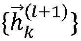
- k U l k U , 1 l ⁇ k U , M l
- a learning rate ⁇ U is an empirical constant updated through a series of iterations: ⁇ ⁇ ⁇ l ⁇ k l ⁇ ⁇ l + 1 ⁇ ⁇ , so that finally the gradient k U l ⁇ 0 , which means that the waveform is close to an optimal value ⁇ opt , and basically does not change any more ⁇ A l + 1 ⁇ ⁇ A l .
- the formula (36) is just the simplest model, and other more complex models may be chosen; second, for high-dimensional optimization problems, it is also important to choose an initial value; third, although the optimized waveform can be obtained purely through numerical calculations, such a waveform does not necessarily lead to a high-precision CZ gate in an actual experiment since there are often some uncontrollable errors in the experiment.
- a data-driven method is adopted in the present disclosure to partially avoid the foregoing third problem.
- the term “partially avoid” here means that some parameters in the experiment, such as a coupling strength calibration error and a waveform generation error, can be reduced through optimization as much as possible.
- inherent defects of a bit such as an excessively short decoherence time, cannot be prevented.
- a feasible manner is provided, a process matrix measured through QPT is estimated by using he Powell algorithm, so as to find the actual gate operator U exp .
- the formula (35) may be changed to: k U ; m l ⁇ 2 ⁇ ImTr Q c ; m l U exp l ⁇ U CZ + 2 ⁇ ImTr Q d ; m l U exp l U CZ
- the gradient is combined with feedback of experimental measurement data, the quantum gate is updated by using the experimental results, thereby converging more effectively, and thus improving the final precision of the quantum gate.
- ⁇ t ⁇ i H t , ⁇ t + ⁇ s L s ⁇ t L s ⁇ ⁇ 1 2 ⁇ t , L s ⁇ L s
- H ( t ) represents a total system Hamiltonian
- ⁇ L s ⁇ represents a set of Lindblad operators indicating dissipation.
- i represents an imaginary unit.
- L ⁇ i , j , k , l L i , j : k , l
- ⁇ i , j , k i , k ⁇ j , l H i , k ⁇ j , l ⁇ H l , j ⁇ i , k ⁇ k , l
- L sys ⁇ i , j , k , l H i , k ⁇ j , l ⁇ H l , j ⁇ i , k
- L s ⁇ i , j , k , l L s ; i , k L s ; l , j ⁇ ⁇ 1 2 L s ⁇ L s l , j ⁇ i , k ⁇ 1 2 L s ⁇ L s i , k ⁇ l , j
- L relax ⁇ i , j , k , l 1 T 1 kl ⁇ i + 1 , k ⁇ j + 1 , l ⁇ 1 2 i + l ⁇ i , k ⁇ j , l
- L deph ⁇ i , j , k , l ⁇ 1 T ⁇ i ⁇ l 2 ⁇ i , k ⁇ j , l
- U T represents a super operator that a density matrix in the Liouville space evolves with time
- i represents an imaginary unit.
- U c represents the time evolution super operator of a coupling term
- U d represents the time evolution super operator of a decoupling term:
- Q c;m represents a calculated value of a coupling term corresponding to the m-th pulse waveform
- Q d;m a calculated value of a decoupling term corresponding to the m-th pulse waveform
- i an imaginary unit:
- a learning rate ⁇ ⁇ is an empirical constant.
- an initial control external field may be selected by the following methods.
- a control pulse of the CZ gate may be designed as a function with different waveforms. It is usually necessary to select a relatively smooth waveform to reduce a filtering effect existing in a circuit. For a waveform with a short rise time (such as a square wave), the filtering effect in the circuit is equivalent to performing a Fourier transform on a square wave on a spectrum. Because a high-order harmonic spectrum of the square wave is wide, a large range of the spectrum is affected. However, for a relatively smooth waveform, an affected spectrum is relatively narrow. Therefore, a smooth waveform is less affected by filtering.
- ⁇ t ⁇ 2 erf 4 ln 2 ⁇ t ⁇ t 0 + ⁇ ⁇ erf 4 ln 2 ⁇ t ⁇ t 0 + T ⁇ ⁇
- ⁇ and T respectively represent an amplitude and a time length of a pulse of an initialized control external field
- ⁇ is related to curvature of an edge of the pulse
- ⁇ -492.5/2 ⁇ MHz
- T 52 ns
- ⁇ 3 ns.
- a more complex model is established.
- the actual error effects (such as the filtering effect) are taken into consideration in the Hamiltonian of the system, thereby calculating a more precise gradient.
- the obtained gradient is corrected with reference to some boundary conditions given in an actual system, or applying some gradient correction algorithms (such as the gradient correction in the Adam algorithm commonly used in deep learning) to an iteration based on the GRAPE.
- some gradient correction algorithms such as the gradient correction in the Adam algorithm commonly used in deep learning
- the GRAPE algorithm is combined with other algorithms.
- an optimized control external field functions as the initial control external field and is introduced into other algorithms, and some new parameters may be selected for optimization.
- a CZ gate can be optimized experimentally.
- a specific implementation is as follows. As shown in FIG. 3 , through the operations of ⁇ I , X , ⁇ Y /2 , ⁇ X /2 ⁇ , two bits are each prepared to 6 different initial states, and there is a total of 36 initial states. In the l th iteration step, a particular pulse ⁇ A l t is applied to a target bit.
- a final state after passing through the CZ gate is measured through QST.
- the gate operator U exp l in an experiment needs to be used in an iteration process.
- the process matrix ⁇ ( l ) is obtained through the QPT measurement. Therefore, it is necessary to find the corresponding U exp l .
- U exp l can be well estimated.
- trivial dynamic phases of two bits, ⁇ A and ⁇ B can be calibrated by using the Ramsey method and compensates for a quantum gate operation after ⁇ A l t . Therefore, U exp l obtained by analyzing the QPT result automatically includes an auxiliary operator U d l ⁇ without coupling interaction. Because a real system includes a lot of extra noise, the CZ gate is not completely unitary.
- a waveform ⁇ A l + 1 of a next step is calculated according to the formula (36).
- the discretized waveform may be changed into a continuous waveform by re-interpolation and the continuous waveform is sent to the AWG for a next iteration.
- an initial state is selected.
- the selection of the initial state may be diverse.
- two initial states, ⁇ (0) (
- 1 ⁇ )/2 and ⁇ ' (0) (
- 1 ⁇ )/2 can be considered, which can be obtained by applying revolving gates of ⁇ Y/2, - Y/2 ⁇ and ⁇ - Y/2, Y/2 ⁇ to a base state respectively.
- the two initial states are selected to partially offset impact caused by experimental preparation and measurement errors. Similarly, it is started from the initial waveform ⁇ A 0 t of the first solution.
- an external field with a waveform ⁇ A l t is applied, and output quantum states of the two selected initial states after passing through the external field are measured through the QST.
- An exemplary value of the learning rate is ⁇ ⁇ ⁇ 0.06 GHz 2 .
- the waveform ⁇ A l + 1 is similarly changed into a continuous waveform by interpolation and the continuous waveform is sent to the AWG.
- Two different data-driven GRAPE optimization solutions for CZ gate optimization are provided according to the present disclosure.
- the two solutions are respectively based on a gate operator and a particular output density matrix, and an optimal control external field is obtained by minimizing two different objective functions.
- the key point of each solution is to calculate a gradient vector by utilizing mixed information of an input control external field and an experimental measurement value (an actual gate operator or an actual output density matrix).
- an actual gate operator or an actual output density matrix Based on the theory, a two-bit CZ gate is optimized by utilizing the SC quantum bit system according to the present disclosure.
- the GRAPE algorithm is relatively efficient in terms of an optimization speed, especially for a case that a parameter space is large.
- FIG. 5 shows a block diagram of an apparatus for optimizing a quantum gate according to an embodiment of the present disclosure.
- the apparatus has functions of implementing the foregoing method embodiments. The functions may be implemented by hardware, or may be implemented by hardware executing corresponding software.
- the apparatus may be the computer device described above, or may be arranged in the computer device.
- an apparatus 500 may include: an external field obtaining module 510, a data acquisition module 520, a gradient calculation module 530, and an external field update module 540.
- the external field obtaining module 510 is configured to obtain an initialized control external field corresponding to a quantum gate.
- the data acquisition module 520 is configured to apply the control external field to a quantum bit of the quantum gate and acquire actual measurement data of the quantum gate.
- the actual measurement data is configured to reflect an actual characteristic of the quantum gate.
- the gradient calculation module 530 is configured to calculate a gradient of the control external field based on the actual measurement data and ideal data.
- the external field update module 540 is configured to update the control external field according to the gradient to obtain an updated control external field.
- the updated control external field is applied to the quantum bit of the quantum gate to optimize precision of the quantum gate.
- the gradient calculation module 530 is configured to:
- the actual measurement data includes an actual gate operator of the quantum gate.
- the data acquisition module 520 is configured to perform QPT on the quantum gate to obtain a process matrix corresponding to the quantum gate; and determine the actual gate operator corresponding to the quantum gate based on the process matrix corresponding to the quantum gate.
- the actual measurement data includes an actual output density matrix corresponding to the quantum gate.
- the data acquisition module 520 is configured to obtain at least one selected input quantum state; process the input quantum state through the quantum gate to obtain an output quantum state; and perform QST on the output quantum state to obtain an actual output density matrix corresponding to the quantum gate.
- the external field update module 540 is configured to calculate an updated value according to the gradient and a learning rate; and calculate the updated control external field according to a current control external field and the updated value.
- the data acquisition module 520 is configured to divide the control external field by time to obtain a pulse waveform sequence, the pulse waveform sequence including pulse waveforms corresponding to multiple time instants; and apply the pulse waveforms corresponding to the multiple time instants to the quantum bit of the quantum gate.
- the apparatus 500 further includes a condition determining module (which is not shown in FIG. 5 ).
- the condition determining module is configured to:
- the optimization end condition includes at least one of the following: the actual characteristic of the quantum gate reflected by the actual measurement data reaches a set index, and a change of the control external field before and after the update is less than a set value.
- the quantum gate optimization solution provided in the present disclosure is a closed-loop optimization solution driven and implemented by data feedback.
- an optimization algorithm based on gradient constraint is combined with actual measurement data.
- the control external field is optimized based on gradient constraint, an optimization time can be shortened and optimization costs can be reduced as compared with some optimization solution without gradient constraints.
- the actual measurement data of the quantum gate is acquired during the optimization process, and optimization is performed by using the actual measurement data as feedback, thereby ensuring the effect and precision of optimization.
- the apparatus provided in the above embodiment is described based on functional modules for implementing specific functions, and the apparatus is not limited to be implemented as above.
- the functions may be assigned to and completed by different functional modules according to the requirements, that is, the device is divided into different functional modules, to implement all or some of the functions described above.
- the apparatus provided in the foregoing embodiments and method embodiments belong to the same concept. For the specific implementation process, one may refer to description of the method embodiments, and details are not described herein again.
- FIG. 6 is a structural block diagram of a computer device according to an embodiment of the present disclosure.
- the computer device may be configured to implement the method for optimizing a quantum gate provided in the foregoing embodiments.
- the computer device is a classic computer.
- a computer device 600 includes a processing unit (for example, a central processing unit (CPU), a graphics processing unit (GPU) and a field programmable gate array (FPGA), etc.) 601, a system memory 604 including a random-access memory (RAM) 602 and a read-only memory (ROM) 603, and a system bus 605 connecting the system memory 604 and the central processing unit 601.
- the computer device 600 further includes a basic input/output (I/O) system 606 assisting in transmitting information between components in a server, and a mass storage device 607 configured to store an operating system 613, an application program 614, and another program module 615.
- I/O basic input/output
- the basic I/O system 606 includes a display 608 configured to display information and an input device 609, such as a mouse or a keyboard, for a user to input information.
- the display 608 and the input device 609 are both connected to the CPU 601 by using an input/output controller 610 connected to the system bus 605.
- the basic I/O system 606 may further include the I/O controller 610 to receive and process inputs from multiple other devices such as a keyboard, a mouse, or an electronic stylus.
- the I/O controller 610 further provides an output to a display screen, a printer or another type of an output device.
- the mass storage device 607 is connected to the CPU 601 by using a mass storage controller (which is not shown) connected to the system bus 605.
- the mass storage device 607 and an associated computer-readable medium provide non-volatile storage for the computer device 600. That is, the mass storage device 607 may include a computer-readable medium (which is not shown) such as a hard disk or a compact disc read-only memory (CD-ROM) drive.
- a computer-readable medium which is not shown
- CD-ROM compact disc read-only memory
- the computer-readable medium may include a computer storage medium and a communication medium.
- the computer storage medium includes volatile and non-volatile media, and removable and non-removable media implemented by using any method or technology used for storing information such as computer-readable instructions, data structures, program modules, or other data.
- the computer storage medium includes an RAM, a ROM, an erasable programmable read-only memory (EPROM), an electrically erasable programmable read-only memory (EEPROM), a flash memory or another solid-state memory technology, a CD-ROM, a digital video disc (DVD) or another optical memory, a tape cartridge, a magnetic cassette, a magnetic disk memory, or another magnetic storage device.
- EPROM erasable programmable read-only memory
- EEPROM electrically erasable programmable read-only memory
- flash memory or another solid-state memory technology
- CD-ROM compact disc
- DVD digital video disc
- types of the computer storage medium are not limited to the foregoing types.
- the computer device 600 may be further connected, through a network such as the Internet, to a remote computer on the network and run. That is, the computer device 600 may be connected to a network 612 by using a network interface unit 611 connected to the system bus 605, or may be connected to another type of network or a remote computer system (which is not shown) by using a network interface unit 611.
- the memory further includes at least one instruction, at least one program, a code set, or an instruction set.
- the at least one instruction, the at least one program, the code set, or the instruction set is stored in the memory and is configured to be executed by one or more processors to implement the foregoing method for optimizing a quantum gate.
- a computer-readable storage medium is further provided, storing at least one instruction, at least one program, a code set, or an instruction set.
- the at least one instruction, the at least one program, the code set, or the instruction set when executed by a processor, implements the method for optimizing a quantum gate.
- the computer-readable storage medium may include a read-only memory (ROM), a random-access memory (RAM), a solid state drive (SSD), an optical disc, or the like.
- the RAM may include a resistive random access memory (ReRAM) and a dynamic random access memory (DRAM).
- a computer program product or a computer program includes computer instructions, and the computer instructions are stored in a computer-readable storage medium.
- the processor of the computer device reads the computer instructions from the computer-readable storage medium, and executes the computer instructions, to cause the computer device to perform the foregoing method for optimizing a quantum gate.
- the term of "plurality of” or “multiple” mentioned herein means two or more.
- the term of "and/or” describes an association relationship between associated objects and represents that three relationships may exist.
- a and/or B may represent the following three cases: only A exists, both A and B exist, and only B exists.
- the character "/" herein generally indicates an "or” relationship between the associated objects.
- the step numbers described herein merely exemplarily show a possible execution sequence of the steps. In some other embodiments, the steps may not be performed according to the number sequence. For example, two steps with different numbers may be performed simultaneously, or two steps with different numbers may be performed according to a sequence contrary to the sequence shown in the figure. This is not limited in the embodiments of the present disclosure.
Landscapes
- Engineering & Computer Science (AREA)
- Theoretical Computer Science (AREA)
- Physics & Mathematics (AREA)
- General Physics & Mathematics (AREA)
- Evolutionary Computation (AREA)
- General Engineering & Computer Science (AREA)
- Condensed Matter Physics & Semiconductors (AREA)
- Data Mining & Analysis (AREA)
- Mathematical Analysis (AREA)
- Mathematical Optimization (AREA)
- Pure & Applied Mathematics (AREA)
- Computing Systems (AREA)
- Computational Mathematics (AREA)
- Mathematical Physics (AREA)
- Software Systems (AREA)
- Artificial Intelligence (AREA)
- Computer Hardware Design (AREA)
- Geometry (AREA)
- Superconductor Devices And Manufacturing Methods Thereof (AREA)
Abstract
Description
- This application claims priority to
Chinese Patent Application No. 202110410057.9, titled "METHOD AND APPARATUS FOR OPTIMIZING QUANTUM GATE, DEVICE, AND STORAGE MEDIUM" filed on April 15, 2021 - Embodiments of the present disclosure relate to the technical field of quantum, and in particular to a method and an apparatus for optimizing a quantum gate, a device, and a storage medium.
- A quantum gate is a basic component of a quantum circuit. Multiple quantum gates are combined to construct a complex quantum circuit, so as to implement quantum computing and quantum simulation. Therefore, the implementation of high-precision quantum gates is essential for the quantum computing and quantum simulation.
- Currently, none of the quantum gate optimization solutions can improve both the precision and efficiency.
- According to embodiments of the present disclosure, a method and an apparatus for optimizing a quantum gate, a device, and a storage medium are provided, to provide a quantum gate optimization solution that improves both the precision and efficiency. The technical solutions are as follows.
- According to an aspect of the embodiments of the present disclosure, a method for optimizing a quantum gate is provided. The method is performed by a computer device, and the method includes:
- obtaining an initialized control external field corresponding to a quantum gate;
- applying the control external field to a quantum bit of the quantum gate, and acquiring actual measurement data of the quantum gate, where the actual measurement data is configured to reflect an actual characteristic of the quantum gate;
- calculating a gradient of the control external field based on the actual measurement data and ideal data; updating the control external field according to the gradient to obtain an updated control external field; and
- applying the updated control external field to the quantum bit of the quantum gate to optimize precision of the quantum gate.
- According to an aspect of the embodiments of the present disclosure, an apparatus for optimizing a quantum gate is provided. The apparatus includes: an external field obtaining module, a data acquisition module, a gradient calculation module and an external field update module.
- The external field obtaining module is configured to obtain an initialized control external field corresponding to a quantum gate.
- The data acquisition module is configured to apply the control external field to a quantum bit of the quantum gate, and acquire actual measurement data of the quantum gate. The actual measurement data is configured to reflect an actual characteristic of the quantum gate.
- The gradient calculation module is configured to calculate a gradient of the control external field based on the actual measurement data and ideal data.
- The external field update module is configured to update the control external field according to the gradient to obtain an updated control external field. The updated control external field is applied to the quantum bit of the quantum gate to optimize precision of the quantum gate.
- According to an aspect of the embodiments of the present disclosure, a computer device is provided, including a processor and a memory. The memory stores at least one instruction, at least one program, a code set, or an instruction set. The at least one instruction, the at least one program, the code set, or the instruction set is loaded and executed by the processor to implement the foregoing method for optimizing a quantum gate.
- According to an aspect of the embodiments of the present disclosure, a computer-readable storage medium is provided. The computer-readable storage medium stores at least one instruction, at least one program, a code set, or an instruction set, and the at least one instruction, the at least one program, the code set, or the instruction set is loaded and executed by the processor to implement the foregoing method for optimizing a quantum gate.
- According to an aspect of the embodiments of the present disclosure, a computer program product or a computer program is provided, including computer instructions. The computer instructions are stored in a computer-readable storage medium. A processor of a computer device reads the computer instructions from the computer-readable storage medium, and executes the computer instructions, to cause the computer device to perform the foregoing method for optimizing a quantum gate.
- The technical solutions provided in the embodiments of the present disclosure can achieve at least the following beneficial effects.
- The quantum gate optimization solution provided in the present disclosure is a closed-loop optimization solution driven and implemented by data feedback. In the present disclosure, an optimization algorithm based on gradient constraint is combined with actual measurement data. On one hand, the control external field is optimized based on gradient constraint, an optimization time can be shortened and optimization costs can be reduced as compared with some optimization solution without gradient constraints. On the other hand, the actual measurement data of the quantum gate is acquired during the optimization process, and optimization is performed by using the actual measurement data as feedback, thereby ensuring the effect and precision of optimization. With reference to the foregoing two aspects, a quantum gate optimization solution that improves both the precision and efficiency is provided according to the present disclosure.
- To describe the technical solutions of the embodiments of the present disclosure clearer, the accompanying drawings required for describing the embodiments are briefly introduced hereinafter. Apparently, the accompanying drawings in the following description show only some embodiments of the present disclosure, and a person of ordinary skill in the art may derive other drawings from these accompanying drawings without creative efforts.
-
FIG. 1 is a schematic structural diagram of an experimental platform for a superconducting quantum computer according to the present disclosure. -
FIG. 2 is a flowchart of a method for optimizing a quantum gate according to the present disclosure. -
FIG. 3 is a schematic diagram of an optimization solution based on a gate operator according to the present disclosure. -
FIG. 4 is a schematic diagram of an optimization solution based on an output density matrix according to the present disclosure. -
FIG. 5 is a block diagram of an apparatus for optimizing a quantum gate according to the present disclosure. -
FIG. 6 is a structural block diagram of a computer device according to the present disclosure. - To make the objectives, technical solutions, and advantages of the present disclosure clearer, implementations of the present disclosure are described in detail with reference to the accompanying drawings hereinafter.
- Before embodiments of the present disclosure are described, some terms involved in the present disclosure are explained first.
- 1. Quantum computing (QC): a novel computing method in which calculation is performed by running algorithms according to principles of superposition and entanglement of quantum states in quantum mechanics.
- 2. Quantum bit (Qubit): a two-level quantum system, which is a basic unit of quantum computing and may be implemented on different physical carriers.
- 3. Superconducting quantum bit (SC Qubit): a quantum bit based on a superconducting quantum circuit designed and fabricated by using a micro-nano processing technology. Through classical microwave pulse signals, control and quantum state measurement of the SC qubit can be implemented.
- 4. Quantum circuit and quantum gate: Quantum circuit is a quantum computing model in which a quantum computing process is decomposed into a series of quantum gate operations performed on multiple quantum bits.
- 5. Lindblad equation: an equation used for describing evolution of a density matrix of an open quantum system that satisfies Markov approximation with time under a weak coupling interaction.
- 6. Quantum state tomography (QST): a commonly used method for calibrating quantum states in which projection measurement is performed on the quantum states in different directions to construct a corresponding density matrix.
- 7. Quantum process tomography (QPT): a commonly used method for calibrating a quantum gate, in which different initial states are selected to pass through a specific quantum gate, and corresponding final states are obtained through the QST to construct a process matrix including all information of the quantum gate.
- 8. Randomized benchmarking measurement: n random Clifford gates are selected, and, a base state probability of a gate circuit is obtained through an inverse operation by collecting a large number of statistics, and multiple measurements are performed by changing a value of n, so that an attenuation rate of a waveform sequence can be extracted.
- 9. Interleaved randomized benchmarking measurement: n random Clifford gates are selected, and a target quantum gate that needs to be calibrated is inserted at the end, and, a base state probability of a gate circuit is obtained through an inverse operation by collecting a large number of statistics, and multiple measurements are performed by changing the value of n, so that an attenuation rate of a waveform sequence can be extracted. With reference to results of the randomized benchmarking measurement, the precision of the target quantum gate is further calibrated.
- 10. GRAPE algorithm: a gradient ascent pulse engineering algorithm, in which a gradient of a discretized waveform is calculated based on a defined objective function, and multiple iterations are performed, so that a waveform converges to near an optimal value.
- 11. Powell algorithm: an accelerated algorithm in which a one-dimensional search is performed sequentially on a multi-dimensional objective function based on a conjugate direction to find a minimum value.
- 12. Nelder-Mead algorithm: a gradient-free algorithm for finding a minimum value of a multivariate function, of which the core is to update an initially selected simplex according to specific rules until the simplex is small enough, so as to find an optimized parameter at this time.
- 13. Control external field: with regard to the SC qubit, a control external field generally refers to a microwave drive applied to a qubit. A microwave applied to a diagonal element part of a bit Hamiltonian is referred to as a control external field in a z direction. A microwave applied to a non-diagonal element part of the bit Hamiltonian is referred to as a control external field in an xy direction.
- 14. Two-bit probability exchange: after a bit is prepared to an excited state and if another bit is coupled to the bit, the probability of the excited state is exchanged between the two bits. The exchange capability is decreased as the coupling strength is decreased.
- 15. Trivial dynamic phase: without considering an inter-bit coupling effect, due to the external field in the z direction, a cumulative phase introduced in the diagonal element of the bit is generally referred to as a trivial dynamic phase.
-
FIG. 1 is a schematic structural diagram of an experimental platform for a superconducting quantum computer according to an exemplary embodiment of the present disclosure. Adilution refrigerator 11 is located on the rightmost side ofFIG. 1 , and is configured to provide a working environment for a quantum chip 15 (such as a superconducting quantum chip). Thequantum chip 15 works at a temperature of 10 mk. Thequantum chip 15 is controlled by analog waveforms, and therefore, implements control and measurement through a measurement andcontrol system 12 mainly including a field programmable gate array (FPGA) and an analog-to-digital converter (ADC)/digital-to-analog converter (DAC). The measurement andcontrol system 12 is controlled by measurement and control software of ahost computer 13, and the measurement and control software determines an experiment to be carried out currently, and performs experimental configurations on the measurement andcontrol system 12, and the like. Thehost computer 13 may be a classic computer such as a personal computer (PC). - An ideal gate operator may be equivalent to a time evolution operator that completely depends on a control external field. Therefore, optimization of a quantum gate may be equivalent to optimization of the control external field corresponding to the quantum gate. The quantum gate optimization solution provided in the present disclosure is a closed-loop optimization solution driven and implemented by data feedback. In the present disclosure, an optimization algorithm based on gradient constraint is combined with actual measurement data. On one hand, the control external field is optimized based on gradient constraint, an optimization time can be shortened and optimization costs can be reduced as compared with some optimization solution without gradient constraints. On the other hand, the actual measurement data of the quantum gate is acquired during the optimization process, and optimization is performed by using the actual measurement data as feedback, thereby ensuring the effect and precision of optimization. With reference to the foregoing two aspects, a quantum gate optimization solution that improves both the precision and efficiency is provided according to the present disclosure.
- Before method embodiments of the present disclosure are described, an operating environment of the method is described first. A method for optimizing a quantum gate provided in the embodiments of the present disclosure may be performed and implemented by a classic computer (such as a PC). For example, the method may be implemented by a classic computer executing a corresponding computer program. Alternatively, the method may be implemented in a hybrid device environment including a classic computer and a quantum computer. For example, the method is implemented by a classic computer and a quantum computer cooperating with each other.
- In the following method embodiments, for convenience of description, the description is provided by assuming that steps are performed by a computer device. It is to be understood that the computer device may be a classic computer, or may be a hybrid execution environment including a classic computer and a quantum computer. A type of the computer device is not limited in the embodiments of the present disclosure.
- In addition, in the embodiments of the present disclosure, a controlled Z (CZ) quantum gate (CZ gate for short) is mainly used as an example to illustrate the technical solutions of the present disclosure. The technical solutions provided in the present disclosure adapt to not only optimization of the CZ gate, but also optimization of some other quantum gates, for example, some common single-bit quantum gates (such as Rx, Ry, and Rz quantum gates) and some other complex quantum gates.
-
FIG. 2 is a flowchart of a method for optimizing a quantum gate according to an exemplary embodiment of the present disclosure. All steps of the method may be performed by a computer device. The method may include the following steps (210 to 240). - In
step 210, an initialized control external field corresponding to a quantum gate is obtained. - In the embodiments of the present disclosure, a control external field refers to a microwave drive applied to a quantum bit of a quantum gate, and the control external field may be a pulse waveform. The initialized control external field may be selected based on experience or experiments.
- In the embodiments of the present disclosure, multiple iterative updates are performed on the control external field to optimize the control external field, and the optimized control external field is applied to the quantum bit of the quantum gate, thereby optimizing precision of the quantum gate.
- The core of quantum gate optimization is to improve the precision. Precision, also referred to as fidelity, refers to the comparison between a measurement result and an ideal value. Experimentally, the precision of a quantum gate is generally measured by methods such as the QPT and randomized benchmarking measurement.
- In
step 220, the control external field is applied to the quantum bit of the quantum gate, and actual measurement data of the quantum gate is acquired. The actual measurement data is configured to reflect an actual characteristic of the quantum gate. - In an embodiment, the control external field is applied to the quantum bit of the quantum gate in the following manner: dividing the control external field by time to obtain a pulse waveform sequence, the pulse waveform sequence including pulse waveforms corresponding to multiple time instants; and applying the pulse waveforms corresponding to the multiple time instants to the quantum bit of the quantum gate. For example, in a case that the control external field is denoted as µA (t), 0 < t < T, and the time T is divided into M parts (τ = T/M), then the control external field µA (t) is discretized as:

- In a case that the quantum gate is a single-bit quantum gate, the control external field may be applied to the single bit of the quantum gate. In a case that the quantum gate is a multi-bit quantum gate, the corresponding control external field may be applied to only one or some of multiple bits of the quantum gate. For example, for a two-bit CZ gate, the control external field may be applied to only one of the bits.
- The quantum gate optimization solution provided in the embodiments of the present disclosure is a closed-loop optimization solution driven and implemented by data feedback. Therefore, after the control external field is applied to the quantum bit of the quantum gate, and the actual measurement data of the quantum gate is acquired through experiments. The actual measurement data is configured to reflect the actual characteristic of the quantum gate, so that the closed-loop optimization of the quantum gate (the control external field) is realized by utilizing the actual measurement data.
- In an exemplary embodiment, the actual measurement data includes an actual gate operator corresponding to the quantum gate. In an embodiment, QPT is performed on the quantum gate to obtain a process matrix corresponding to the quantum gate; and based on the process matrix corresponding to the quantum gate, the actual gate operator of the quantum gate is determined.
- The process matrix corresponding to the quantum gate is generally obtained through the QPT. The QPT is a technique for describing performance of a specific quantum gate, and can provide a visual image related to the process matrix. An ideal unitary evolution can be described directly by the mapping ψf = Uidealψ(0) of quantum states. However, a non-ideal system with noise has to be described by using a density matrix. There is a process matrix-dependent mapping relationship between an input quantum state ρ(0)and an output quantum state ρf , which is expanded into a superposition of a set of linear operators{Bi }:

- In which, d represents a dimension of the system, {Ẽm, Ẽn } represents a set of complete basis vectors and may consist of Pauli matrices, and χmn is a process matrix that describes all information of a specific quantum gate. A process matrix χ can be determined from a specific quantity of the input quantum states and the corresponding output quantum states based on the mapping relationship. A value of i in the formula (2) is an integer and ranges from 1 to d 2. inclusive.
- In an embodiment, the process matrix obtained through the QPT measurement is estimated by using the Powell algorithm to find the actual gate operator of the quantum gate. The Powell algorithm is an accelerated algorithm based on a conjugate direction, and has a good optimization effect for a parameter dimension less than 20. For an objective function, a parameter vector in an N-dimensional space is
X . Starting from an initial guess value


- Experimentally, a behavior of a quantum gate is completely described by the process matrix χ, which can be obtained through the QPT. Due to quantum dissipation and some other error sources, χ exp that is experimentally determined always deviates from an ideal value. Therefore, it is almost impossible to accurately calculate a time evolution operator U corresponding to the quantum gate. However, a fitting method can be adopted to find a best estimate U exp (which is referred to as "the actual gate operator of the quantum gate"). The estimate functions as experimental measurement feedback in an optimization solution based on a gate operator. By constructing a constant matrix M (whose dimension is N2 × N2) with a Pauli matrix as a basis vector, a relationship between a super operatorof a quantum gate and a process matrix χ̃ of the quantum gate presented as a vector is established, that is


X in the N-dimensional space can be defined according to all of N independent elements {Ui }, that is,X ≡X ({Ui }). The objective function is defined as a square difference between a process matrix of a quantum gate U and an experimental measurement value, that is, F=∥χ(U)-χ exp∥2=∥χ(X)-χ exp∥2. The parameter vectorX corresponding to the quantum gate U is optimized by the Powell algorithm to minimize the objective function, so as to find U exp which is closest to the process matrix χ exp measured in an experiment. - In another exemplary embodiment, the actual measurement data includes an actual output density matrix corresponding to the quantum gate. In an embodiment, at least one selected input quantum state is obtained; the input quantum state is processed through the quantum gate to obtain an output quantum state; and QST is performed on the output quantum state to obtain the actual output density matrix corresponding to the quantum gate.
- The quantum state can be determined by using a method of the QST. A basic principle of the QST is to project the quantum state to different directions through a series of revolving gates selected in advance. Based on probabilities measured in different projection directions and maximum likelihood estimation, a density matrix corresponding to the quantum state can be fitted. Therefore, by performing the QST on the output quantum state of the quantum gate, the actual output density matrix corresponding to the quantum gate can be obtained.
- In
step 230, a gradient of the control external field is calculated based on the actual measurement data and ideal data. - In the embodiments of the present disclosure, the gradient of the control external field is calculated based on the actual measurement data and ideal data, and then the control external field is updated according to the gradient. The ideal data is used for reflecting an ideal characteristic of the foregoing quantum gate. For example, in a case that the actual measurement data includes the actual gate operator of the quantum gate, the ideal data includes an ideal gate operator of the quantum gate. In another example, in a case that the actual measurement data includes the actual output density matrix of the quantum gate, the ideal data includes an ideal output density matrix of the quantum gate. The foregoing ideal data (such as the ideal gate operator, and the ideal output density matrix) may be set in advance according to a design of the quantum gate. The optimization algorithm based on gradient constraint has a faster optimization speed than an optimization algorithm without gradient constraints, thereby saving optimization costs.
- In an embodiment, the step includes the following
substeps - In
substep 1, a gradient calculation formula is derived according to an objective function and a waveform function corresponding to the control external field. The objective function is configured to characterize a difference between the actual measurement data and the ideal data, and the objective function is optimized to minimize a value of the objective function. - In
substep 2, by using the gradient calculation formula, the gradient of the control external field is calculated based on the actual measurement data and the ideal data. - The objective function is related to precision of the quantum gate, and the objective function is constructed based on a manner of measuring the precision of the quantum gate. In addition, two solutions are provided in the present disclosure. One solution is an optimization solution based on a gate operator, and the other solution is an optimization solution based on a density matrix. Therefore, the corresponding objective functions and the corresponding gradient calculation formulas are different.
- For the optimization solution based on the gate operator, the actual measurement data includes the actual gate operator of the quantum gate, and the objective function is:

- The corresponding gradient calculation formula is:

- In which, Uc represents a total time evolution operator corresponding to the quantum gate, Ud represents a time evolution operator corresponding to the quantum gate without interbit coupling, U CZ represents an ideal gate operator corresponding to the quantum gate.

- For the optimization solution based on the density matrix, the actual measurement data includes the actual output density matrix corresponding to the quantum gate, and the objective function is:

- The corresponding gradient calculation formula is:

- In which, ρ f represents an output density matrix corresponding to the quantum gate. ρ ideal represents an ideal output density matrix corresponding to the quantum gate. ρ(0) represents an input density matrix corresponding to the quantum gate.


- In
step 240, the control external field is updated according to the gradient to obtain an updated control external field. The updated control external field is applied to the quantum bit of the quantum gate to optimize the precision of the quantum gate. - In an embodiment, an updated value is calculated according to the gradient and a learning rate; and an updated control external field is calculated according to a current control external field and the updated value. For example, the updated value is obtained by multiplying the gradient and the learning rate, and then the updated value is added to the current control external field to obtain the updated control external field. The learning rate is an empirical constant.
- In addition, in the embodiments of the present disclosure, a quantum gate (a control external field) is optimized by using the GRAPE algorithm. In a case that the quantum gate does not meet an optimization end condition,
step 220 is performed again by using the updated control external field as the current control external field; and the optimization process is ended in a case that the quantum gate meets the optimization end condition. In an embodiment, the optimization end condition includes at least one of the following: the actual characteristic of the quantum gate reflected by the actual measurement data reaches a set index, and a change of the control external field before and after the update is less than a set value. - In summary, the quantum gate optimization solution provided in the present disclosure is a closed-loop optimization solution driven and implemented by data feedback. In the present disclosure, an optimization algorithm based on gradient constraint is combined with actual measurement data. On the one hand, the control external field is optimized based on gradient constraint, an optimization time can be shortened and optimization costs can be reduced as compared with some optimization solution without gradient constraints. On the other hand, the actual measurement data of the quantum gate is acquired during the optimization process, and optimization is performed by using the actual measurement data as feedback, thereby ensuring the effect and precision of optimization. With reference to the foregoing two aspects, a quantum gate optimization solution that improves both the precision and efficiency is provided according to the present disclosure.
- By using a CZ gate as an example, a process of optimizing the CZ gate by using the technical solution in the present disclosure is described below.
- In a case that there is no control external field, a Hamiltonian of a two-bit system (A, B)can be expressed as:

- In which, H i=A,B represents a Hamiltonian of a single bit, I i=A,B represents a unit operator, and Hint represents interaction between two bits. The CZ gate is implemented by a second excited state of one of the bits. A three-level single-bit Hamiltonian (ℏ = 1, where h represents a reduced Planck constant, which is set to be 1 in a natural unit for convenience) is expressed as:

- For each bit (i = A, B), ωi and Δ i respectively represent a resonant frequency and anharmonicity of the bit. A parameter example of an experimental bit sample is provided herein, that is, ωA /2π = 5.176 GHz, ωB /2π = 4.438 GHz, and Δ A /2π = -245.2 MHz, Δ B /2π = -255.5 MHz.
- In addition, an interaction Hamiltonian of the two-bit system (A, B) is:

- In which,


- Due to a weak coupling condition (g << |ωA - ωB|) between the two bits, a probability exchange between the two bits is basically negligible in a case that there is no control external field. However, in a case that a control external field in a z direction is applied, a resonance environment can be created for the two bits. The control external field can be expressed as:

- In which,


- Under such a control external field, the two-bit system can be reduced to a 5-level status for processing. In a simplified 5-level Hilbert space {|00〉, |10〉,|01〉,|11〉,|20〉}, the Hamiltonian of the two-bit quantum system Hc(t) can be expressed as:

- The coupling between |10〉 and |01〉 is neglected here.
- Under a resonance condition µA (t) = µA;r = ωB - ωA - Δ A, the foregoing Hamiltonian Hc(t) can be simplified ito:

- In addition, an auxiliary Hamiltonian Hd (t) without interqubit coupling (g = 0) can be given by the following formula:

- Next, time evolution operators, Uc = exp(-iHcT) and Ud = exp(-iHdT), are constructed, where i represents an imaginary unit. Coupling effect of the Hamiltonian Hc given by the formula (12) only exists in |11〉 and |20〉. In a two-dimensional subspace formed by |11〉 and |20〉, two operators are introduced, I 2 = |11〉〈11| + |20〉〈20| and X 2 = |11〉〈20| + |20〉〈11|. Therefore, the Hamiltonian in the 2×2 subspace can be expressed as:

- In a time period T, a corresponding time evolution operator can be expressed as:

- In which, φA = (ωA + µA;r )T, φB = ωBT, and i represents an imaginary unit. The second term on the right side of the formula (15) represents a rotation operator, which can be expanded into:

- In a case that the evolution time is a half period, that is,


- Therefore, the total time evolution operator is:

- In addition, a time evolution operator without coupling is:

- A time evolution operator with a trivial dynamic phase removed is:

- In a case that an initial state is selected only from a subspace {|00〉,|10〉,|01〉,|11〉}, the last term on the right side of the formula (20) is negligible, and the time evolution operator becomes an ideal CZ gate.
- Due to inevitable errors in an evolution process, a simple square pulse (µA (0 < t < T) = µA;r ) as a control external field cannot generate a high-fidelity CZ gate. Therefore, a form of a control external field µA (t) needs to be modified. In this case, two Hamiltonians, Hc (t) and Hd (t) are time-dependent, and corresponding time evolution operators need to be modified as


- The Hamiltonian Hc(t) can be discretized into:

- The decoupling Hamiltonian Hd(t) can be discretized into:


- In which, Uc;m = exp(-iHc;mτ), Ud;m = exp(-iHd;mτ), i represents an imaginary unit, and the time evolution operator

- In the optimization solution based on the gate operator, an objective function is defined as:

- Due to discretization of the control external field µA (t),


- An optimization condition is


- To calculate ∂Uc;m /∂µA;m, the time evolution operator needs to be expanded as:

- In addition, the result is applied to obtain:

- Under a normal circumstance, ∂Hc;m /∂µA;m and Hc;m are not commutative. For numerical calculations, an acceptable approximation is adopted in the present disclosure:

- By using the above result, the formula (28) can be simplified into:

- Two variables, PA = ∂Hc;m /∂µA;m = nA ⊗ IB and Rc;m = Uc;mU c;m-1 ··· U c;1 , are introduced, so that the formula (32) can be changed into:

- In which, Qc;m represents a calculated value of a coupling term corresponding to the m-th pulse waveform,


- In which, Qd;m represents a calculated value of a decoupling term corresponding to the m-th pulse waveform,


- In which, Im represents an imaginary component of a complex number, and i represents an imaginary unit.
- Because it is difficult to solve

FIG. 3 . The solution starts from an initial guess waveform (for example, a flattop waveform or another suitable waveform may be selected experimentally),


- In which, a learning rate αU is an empirical constant updated through a series of iterations:


- Therefore, a data-driven method is adopted in the present disclosure to partially avoid the foregoing third problem. The term "partially avoid" here means that some parameters in the experiment, such as a coupling strength calibration error and a waveform generation error, can be reduced through optimization as much as possible. However, inherent defects of a bit, such as an excessively short decoherence time, cannot be prevented. Experimentally, a feasible manner is provided, a process matrix measured through QPT is estimated by using he Powell algorithm, so as to find the actual gate operator U exp. Therefore, in the l th iteration step, the formula (35) may be changed to:

- This is, the gradient is combined with feedback of experimental measurement data, the quantum gate is updated by using the experimental results, thereby converging more effectively, and thus improving the final precision of the quantum gate.
- In view of dissipation, the time evolution of a density matrix is represented by a Lindblad master equation:

- In which, H(t) represents a total system Hamiltonian, and {Ls } represents a set of Lindblad operators indicating dissipation. For two arbitrary operators, A and B in a Hilbert space, [A, B] = AB - BA, and {A, B} = AB + BA, which are respectively expressed as a commutation relationship and an anti-commutation relationship. In which, i represents an imaginary unit.
- To facilitate derivation and numerical calculations, concepts of the Liouville space and the Liouville super operator are introduced. In the Hilbert space with {|i〉} as a basis vector group, the density matrix is expanded into:

- In the Liouville space, the foregoing matrix is converted into a vector form:

- The foregoing formula is defined based on a new basis vector group {|i,j〉〉}, and there is a one-to-one correspondence |i,j〉〉 ⇔ |i〉〈j|. A complex conjugate term |i,j〉〉† = 〈〈i,j| ⇔ |j〉〈i| thereof is introduced, and an inner product thereof is:

- An outer product thereof is: |i,j〉〉〈〈k,l|. A unit operator (matrix) in the Liouville space is expanded into:

- Then, an arbitrary Liouville super operator L is constructed, and a matrix form of which is as follows:

- In which,

- For a general N-dimensional Hilbert space, the system Hamiltonian may be expanded into H = Σi,j Hi,j |i〉〈j|. In the Hilbert space, the commutator is expressed as:

- The formula (40) and formula (41) are applied, and the foregoing formula in the Liouville space can be changed into:

- Therefore, a matrix form of the commutation relationship of the system Hamiltonian is as follows:

- A dissipation term of the Lindblad equation in the formula (38) can be expanded into:

- The corresponding Liouville super operator is expressed as:

- For an energy relaxation part of a single quantum bit (N(≥ 2)), the Lindblad operator is expressed as:

- The corresponding Liouville super operator is expressed as:

- For a phase relaxation part of a single quantum bit, the Lindblad operator is expressed as:

- The corresponding Liouville super operator is expressed as:

- In summary, the Liouville super operator corresponding to a total dissipation term of a single quantum bit is:

- A specific expression of the Liouville super operator is substituted into the Lindblad equation, to obtain a matrix equation that the density matrix evolves with time as follows:

- The total Liouville super operator


- In which,

- Another optimization solution provided in the present disclosure is implemented based on the formula (54) and the formula (55). For a two-quantum bits system in an experiment, either a 5-dimensional Hilbert space with {|00〉,|10〉,|01〉,|11〉,|20〉} as a basis vector or a more comprehensive 9-dimensional Hilbert space with {|iA (= 0,1,2)iB (= 0,1,2)〉} as a basis vector may be considered. Similar to a processing method of the
solution 1, two Hamiltonians, Hc (t) = H0 (g) + Hext (µA (t)) and Hd (t) = H0 (g = 0) + Hext (µA (t)) are introduced in this solution, and correspondingly two Liouville super operators




- The two time evolution super operators are expressed as follows:


- In the foregoing formula,


- Each short period of time is τ = T/M, and i represents an imaginary unit.
- In the optimization solution based on a density matrix, a particular initial state may be selected, for example, ϕ(0) = (|0〉 + |1〉)⊗(|0〉 - |1〉)/2 and p(0) = ϕ(0)ϕ †(0), and whether a final state

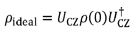


- Similarly, minimization of


- The following approximation is used:


- In addition, the condition


- In the foregoing formula, Qc;m represents a calculated value of a coupling term corresponding to the m-th pulse waveform, Qd;m represents a calculated value of a decoupling term corresponding to the m-th pulse waveform, and i represents an imaginary unit:


- It should be noted that, two items in brackets on the right side of the equation in the formula (67) are pure imaginary numbers, thereby ensuring that a gradient kρ;m is a real number.
- Similarly, an optimization condition

FIG. 4 . The same concept as the first solution is used, that is, starting from an initial guess waveform

- In which, a learning rate αρ is an empirical constant.
- In a case that a waveform converges to near an optimal value,


- In addition, an initial control external field may be selected by the following methods. A control pulse of the CZ gate may be designed as a function with different waveforms. It is usually necessary to select a relatively smooth waveform to reduce a filtering effect existing in a circuit. For a waveform with a short rise time (such as a square wave), the filtering effect in the circuit is equivalent to performing a Fourier transform on a square wave on a spectrum. Because a high-order harmonic spectrum of the square wave is wide, a large range of the spectrum is affected. However, for a relatively smooth waveform, an affected spectrum is relatively narrow. Therefore, a smooth waveform is less affected by filtering. An example of a flattop waveform is provided, and a function of the flattop waveform is:

- In which, erf(x) represents a Gaussian error function, defined as

- In addition, in some other embodiments, in consideration of some determined errors existing in a real quantum system, a more complex model is established. In the complex model, the actual error effects (such as the filtering effect) are taken into consideration in the Hamiltonian of the system, thereby calculating a more precise gradient.
- In some other embodiments, the obtained gradient is corrected with reference to some boundary conditions given in an actual system, or applying some gradient correction algorithms (such as the gradient correction in the Adam algorithm commonly used in deep learning) to an iteration based on the GRAPE.
- In some other embodiments, the GRAPE algorithm is combined with other algorithms. When the gradient cannot guide an effective update of the control external field, an optimized control external field functions as the initial control external field and is introduced into other algorithms, and some new parameters may be selected for optimization.
- Next, experimental implementation of two optimization solutions in an SC qubit system is described.
- By using the foregoing optimization solution based on a gate operator, a CZ gate can be optimized experimentally. A specific implementation is as follows. As shown in
FIG. 3 , through the operations of {I, X, ±Y/2, ±X/2}, two bits are each prepared to 6 different initial states, and there is a total of 36 initial states. In the l th iteration step, a particular pulse


- For such an optimization solution based on a gate operator, the gate operator


- For an optimization solution based on a density matrix, in a theoretical solution, for the sake of simplicity, only an initial state is selected. In fact, the selection of the initial state may be diverse. For example, two initial states, ϕ(0) = (|0〉 + |1〉)⊗(|0〉 - |1〉)/2 and ϕ'(0) = (|0〉 - |1〉)⊗(|0〉 + |1〉)/2 can be considered, which can be obtained by applying revolving gates of {Y/2, - Y/2} and {- Y/2, Y/2} to a base state respectively. The two initial states are selected to partially offset impact caused by experimental preparation and measurement errors. Similarly, it is started from the initial waveform


- Two different data-driven GRAPE optimization solutions for CZ gate optimization are provided according to the present disclosure. The two solutions are respectively based on a gate operator and a particular output density matrix, and an optimal control external field is obtained by minimizing two different objective functions. According to a feedback control mechanism, the key point of each solution is to calculate a gradient vector by utilizing mixed information of an input control external field and an experimental measurement value (an actual gate operator or an actual output density matrix). Based on the theory, a two-bit CZ gate is optimized by utilizing the SC quantum bit system according to the present disclosure. Compared with the related art, the GRAPE algorithm is relatively efficient in terms of an optimization speed, especially for a case that a parameter space is large.
- Apparatus embodiments of the present disclosure are described hereinafter. An apparatus is used for performing the method of the present disclosure. For details not disclosed in the apparatus embodiments of the present disclosure, one may refer to the description of the method embodiments of the present disclosure.
-
FIG. 5 shows a block diagram of an apparatus for optimizing a quantum gate according to an embodiment of the present disclosure. The apparatus has functions of implementing the foregoing method embodiments. The functions may be implemented by hardware, or may be implemented by hardware executing corresponding software. The apparatus may be the computer device described above, or may be arranged in the computer device. As shown inFIG. 5 , anapparatus 500 may include: an externalfield obtaining module 510, adata acquisition module 520, agradient calculation module 530, and an externalfield update module 540. - The external
field obtaining module 510 is configured to obtain an initialized control external field corresponding to a quantum gate. - The
data acquisition module 520 is configured to apply the control external field to a quantum bit of the quantum gate and acquire actual measurement data of the quantum gate. The actual measurement data is configured to reflect an actual characteristic of the quantum gate. - The
gradient calculation module 530 is configured to calculate a gradient of the control external field based on the actual measurement data and ideal data. - The external
field update module 540 is configured to update the control external field according to the gradient to obtain an updated control external field. The updated control external field is applied to the quantum bit of the quantum gate to optimize precision of the quantum gate. - In an exemplary embodiment, the
gradient calculation module 530 is configured to: - derive a gradient calculation formula according to an objective function and a waveform function corresponding to the control external field, where the objective function is configured to characterize a difference between the actual measurement data and the ideal data, and the objective function is optimized to minimize a value of the objective function; and
- calculate, by using the gradient calculation formula, the gradient of the control external field based on the actual measurement data and the ideal data.
- In an exemplary embodiment, the actual measurement data includes an actual gate operator of the quantum gate. The
data acquisition module 520 is configured to perform QPT on the quantum gate to obtain a process matrix corresponding to the quantum gate; and determine the actual gate operator corresponding to the quantum gate based on the process matrix corresponding to the quantum gate. - In an exemplary embodiment, the actual measurement data includes an actual output density matrix corresponding to the quantum gate. The
data acquisition module 520 is configured to obtain at least one selected input quantum state; process the input quantum state through the quantum gate to obtain an output quantum state; and perform QST on the output quantum state to obtain an actual output density matrix corresponding to the quantum gate. - In an exemplary embodiment, the external
field update module 540 is configured to calculate an updated value according to the gradient and a learning rate; and calculate the updated control external field according to a current control external field and the updated value. - In an exemplary embodiment, the
data acquisition module 520 is configured to divide the control external field by time to obtain a pulse waveform sequence, the pulse waveform sequence including pulse waveforms corresponding to multiple time instants; and apply the pulse waveforms corresponding to the multiple time instants to the quantum bit of the quantum gate. - In an exemplary embodiment, the
apparatus 500 further includes a condition determining module (which is not shown inFIG. 5 ). The condition determining module is configured to: - in a case that the quantum gate does not meet an optimization end condition, apply the control external field to the quantum bit of the quantum gate again by using the updated control external field as the current control external field, to update the control external field; and
- end the optimization process in a case that the quantum gate meets the optimization end condition.
- The optimization end condition includes at least one of the following: the actual characteristic of the quantum gate reflected by the actual measurement data reaches a set index, and a change of the control external field before and after the update is less than a set value.
- In view of the above, the quantum gate optimization solution provided in the present disclosure is a closed-loop optimization solution driven and implemented by data feedback. In the present disclosure, an optimization algorithm based on gradient constraint is combined with actual measurement data. On the one hand, the control external field is optimized based on gradient constraint, an optimization time can be shortened and optimization costs can be reduced as compared with some optimization solution without gradient constraints. On the other hand, the actual measurement data of the quantum gate is acquired during the optimization process, and optimization is performed by using the actual measurement data as feedback, thereby ensuring the effect and precision of optimization. With reference to the foregoing two aspects, a quantum gate optimization solution that improves both the precision and efficiency is provided according to the present disclosure.
- It should be noted that, the apparatus provided in the above embodiment is described based on functional modules for implementing specific functions, and the apparatus is not limited to be implemented as above. In the practical application, the functions may be assigned to and completed by different functional modules according to the requirements, that is, the device is divided into different functional modules, to implement all or some of the functions described above. In addition, the apparatus provided in the foregoing embodiments and method embodiments belong to the same concept. For the specific implementation process, one may refer to description of the method embodiments, and details are not described herein again.
-
FIG. 6 is a structural block diagram of a computer device according to an embodiment of the present disclosure. The computer device may be configured to implement the method for optimizing a quantum gate provided in the foregoing embodiments. For example, the computer device is a classic computer. - A
computer device 600 includes a processing unit (for example, a central processing unit (CPU), a graphics processing unit (GPU) and a field programmable gate array (FPGA), etc.) 601, asystem memory 604 including a random-access memory (RAM) 602 and a read-only memory (ROM) 603, and asystem bus 605 connecting thesystem memory 604 and thecentral processing unit 601. Thecomputer device 600 further includes a basic input/output (I/O)system 606 assisting in transmitting information between components in a server, and amass storage device 607 configured to store anoperating system 613, anapplication program 614, and anotherprogram module 615. - The basic I/
O system 606 includes adisplay 608 configured to display information and aninput device 609, such as a mouse or a keyboard, for a user to input information. Thedisplay 608 and theinput device 609 are both connected to theCPU 601 by using an input/output controller 610 connected to thesystem bus 605. The basic I/O system 606 may further include the I/O controller 610 to receive and process inputs from multiple other devices such as a keyboard, a mouse, or an electronic stylus. Similarly, the I/O controller 610 further provides an output to a display screen, a printer or another type of an output device. - The
mass storage device 607 is connected to theCPU 601 by using a mass storage controller (which is not shown) connected to thesystem bus 605. Themass storage device 607 and an associated computer-readable medium provide non-volatile storage for thecomputer device 600. That is, themass storage device 607 may include a computer-readable medium (which is not shown) such as a hard disk or a compact disc read-only memory (CD-ROM) drive. - Without loss of generality, the computer-readable medium may include a computer storage medium and a communication medium. The computer storage medium includes volatile and non-volatile media, and removable and non-removable media implemented by using any method or technology used for storing information such as computer-readable instructions, data structures, program modules, or other data. The computer storage medium includes an RAM, a ROM, an erasable programmable read-only memory (EPROM), an electrically erasable programmable read-only memory (EEPROM), a flash memory or another solid-state memory technology, a CD-ROM, a digital video disc (DVD) or another optical memory, a tape cartridge, a magnetic cassette, a magnetic disk memory, or another magnetic storage device. Certainly, a person skilled in the art may learn that types of the computer storage medium are not limited to the foregoing types. The
system memory 604 and themass storage device 607 may be collectively referred to as a memory. - According to the embodiments of the present disclosure, the
computer device 600 may be further connected, through a network such as the Internet, to a remote computer on the network and run. That is, thecomputer device 600 may be connected to anetwork 612 by using anetwork interface unit 611 connected to thesystem bus 605, or may be connected to another type of network or a remote computer system (which is not shown) by using anetwork interface unit 611. - The memory further includes at least one instruction, at least one program, a code set, or an instruction set. The at least one instruction, the at least one program, the code set, or the instruction set is stored in the memory and is configured to be executed by one or more processors to implement the foregoing method for optimizing a quantum gate.
- In an exemplary embodiment, a computer-readable storage medium is further provided, storing at least one instruction, at least one program, a code set, or an instruction set. The at least one instruction, the at least one program, the code set, or the instruction set, when executed by a processor, implements the method for optimizing a quantum gate.
- In an embodiment, the computer-readable storage medium may include a read-only memory (ROM), a random-access memory (RAM), a solid state drive (SSD), an optical disc, or the like. The RAM may include a resistive random access memory (ReRAM) and a dynamic random access memory (DRAM).
- In an exemplary embodiment, a computer program product or a computer program is provided. The computer program product or the computer program includes computer instructions, and the computer instructions are stored in a computer-readable storage medium. The processor of the computer device reads the computer instructions from the computer-readable storage medium, and executes the computer instructions, to cause the computer device to perform the foregoing method for optimizing a quantum gate.
- The term of "plurality of" or "multiple" mentioned herein means two or more. The term of "and/or" describes an association relationship between associated objects and represents that three relationships may exist. For example, A and/or B may represent the following three cases: only A exists, both A and B exist, and only B exists. The character "/" herein generally indicates an "or" relationship between the associated objects. In addition, the step numbers described herein merely exemplarily show a possible execution sequence of the steps. In some other embodiments, the steps may not be performed according to the number sequence. For example, two steps with different numbers may be performed simultaneously, or two steps with different numbers may be performed according to a sequence contrary to the sequence shown in the figure. This is not limited in the embodiments of the present disclosure.
- The foregoing descriptions are merely exemplary embodiments of the present disclosure, and are not intended to limit the present disclosure. Any modification, equivalent replacement, or improvement made within the spirit and principle of the present disclosure shall fall within the protection scope of the present disclosure.
Claims (23)
- A method for optimizing a quantum gate, performed by a computer device, the method comprising:obtaining an initialized control external field corresponding to a quantum gate;applying the control external field to a quantum bit of the quantum gate, and acquiring actual measurement data of the quantum gate, wherein the actual measurement data is configured to reflect an actual characteristic of the quantum gate;calculating a gradient of the control external field based on the actual measurement data and ideal data;updating the control external field according to the gradient to obtain an updated control external field; andapplying the updated control external field to the quantum bit of the quantum gate to optimize precision of the quantum gate.
- The method according to claim 1, wherein the calculating a gradient of the control external field based on the actual measurement data and ideal data comprises:deriving a gradient calculation formula according to an objective function and a waveform function corresponding to the control external field, wherein the objective function is configured to characterize a difference between the actual measurement data and the ideal data, and the objective function is optimized to minimize a value of the objective function; andcalculating, by using the gradient calculation formula, the gradient of the control external field based on the actual measurement data and the ideal data.
- The method according to claim 2, wherein the actual measurement data comprises an actual gate operator of the quantum gate, and the objective function is:


- The method according to claim 2, wherein the actual measurement data comprises an actual output density matrix corresponding to the quantum gate, and the objective function is:


- The method according to claim 1, wherein the actual measurement data comprises an actual gate operator of the quantum gate;
and wherein the acquiring actual measurement data of the quantum gate comprises:performing quantum process tomography on the quantum gate to obtain a process matrix corresponding to the quantum gate; anddetermining the actual gate operator corresponding to the quantum gate based on the process matrix corresponding to the quantum gate. - The method according to claim 1, wherein the actual measurement data comprises an actual output density matrix corresponding to the quantum gate;
and wherein the acquiring actual measurement data of the quantum gate comprises:obtaining at least one selected input quantum state;processing the input quantum state through the quantum gate to obtain an output quantum state; andperforming quantum state tomography QST on the output quantum state to obtain the actual output density matrix corresponding to the quantum gate. - The method according to claim 1, wherein the updating the control external field according to the gradient to obtain an updated control external field comprises:calculating an updated value according to the gradient and a learning rate; andcalculating the updated control external field according to a current control external field and the updated value.
- The method according to claim 1, wherein the applying the control external field to a quantum bit of the quantum gate comprises:dividing the control external field by time to obtain a pulse waveform sequence, wherein the pulse waveform sequence comprises pulse waveforms corresponding to a plurality of time instants; andapplying the pulse waveforms corresponding to the plurality of time instants to the quantum bit of the quantum gate.
- The method according to claim 1, wherein after the updating the control external field according to the gradient to obtain an updated control external field, the method further comprises:in a case that the quantum gate does not meet an optimization end condition, applying the control external field to a quantum bit of the quantum gate again by taking the updated control external field as the current control external field, to update the control external field; andending the optimization process in a case that the quantum gate meets the optimization end condition,wherein the optimization end condition comprises at least one of: the actual characteristic of the quantum gate reflected by the actual measurement data reaches a set index, and a change of the control external field before and after the update is less than a set value.
- The method according to any one of claims 1 to 9, wherein a waveform function corresponding to the initialized control external field is:


- An apparatus for optimizing a quantum gate, comprising:an external field obtaining module, configured to obtain an initialized control external field corresponding to a quantum gate;a data acquisition module, configured to apply the control external field to a quantum bit of the quantum gate, and acquire actual measurement data of the quantum gate, wherein the actual measurement data is configured to reflect an actual characteristic of the quantum gate;a gradient calculation module, configured to calculate a gradient of the control external field based on the actual measurement data and ideal data; andan external field update module, configured to update the control external field according to the gradient to obtain an updated control external field, and apply the updated control external field to the quantum bit of the quantum gate to optimize precision of the quantum gate.
- The apparatus according to claim 11, wherein the gradient calculation module is configured to:derive a gradient calculation formula according to an objective function and a waveform function corresponding to the control external field, wherein the objective function is configured to characterize a difference between the actual measurement data and the ideal data, and the objective function is optimized to minimize a value of the objective function; andcalculate, by using the gradient calculation formula, the gradient of the control external field based on the actual measurement data and the ideal data.
- The apparatus according to claim 12, wherein the actual measurement data comprises an actual gate operator of the quantum gate, and the objective function is:


- The apparatus according to claim 12, wherein the actual measurement data comprises an actual output density matrix corresponding to the quantum gate, and the objective function is:


- The apparatus according to claim 11, wherein the actual measurement data comprises an actual gate operator corresponding to the quantum gate;
and wherein the data acquisition module is configured to:perform quantum process tomography on the quantum gate to obtain a process matrix corresponding to the quantum gate; anddetermine the actual gate operator corresponding to the quantum gate based on the process matrix corresponding to the quantum gate. - The apparatus according to claim 11, wherein the actual measurement data comprises an actual output density matrix corresponding to the quantum gate;
and wherein the data acquisition module is configured to:obtain at least one selected input quantum state;process the input quantum state through the quantum gate to obtain an output quantum state; andperform quantum state tomography on the output quantum state to obtain the actual output density matrix corresponding to the quantum gate. - The apparatus according to claim 11, wherein the external field update module is configured to:calculate an updated value according to the gradient and a learning rate; andcalculate the updated control external field according to a current control external field and the updated value.
- The apparatus according to claim 11, wherein the data acquisition module is configured to:divide the control external field by time to obtain a pulse waveform sequence, wherein the pulse waveform sequence comprises pulse waveforms corresponding to a plurality of time instants; andapply the pulse waveforms corresponding to the plurality of time instants to the quantum bit of the quantum gate.
- The apparatus according to claim 11, further comprising a condition determining module, configured to:in a case that the quantum gate does not meet an optimization end condition, apply the control external field to a quantum bit of the quantum gate again by taking the updated control external field as the current control external field, to update the control external field; andend the optimization process in a case that the quantum gate meets the optimization end condition,wherein the optimization end condition comprising at least one of: the actual characteristic of the quantum gate reflected by the actual measurement data reaches a set index, and a change of the control external field before and after the update is less than a set value.
- The apparatus according to any one of claims 11 to 19, wherein a waveform function corresponding to the initialized control external field is:


- A computer device, comprising a processor and a memory, wherein the memory stores at least one instruction, at least one program, a code set, or an instruction set, the at least one instruction, the at least one program, the code set, or the instruction set is loaded and executed by the processor to implement the method for optimizing a quantum gate according to any one of claims 1 to 10.
- A computer-readable storage medium, storing at least one instruction, at least one program, a code set, or an instruction set, wherein the at least one instruction, the at least one program, the code set, or the instruction set is loaded and executed by a processor to implement the method for optimizing a quantum gate according to any one of claims 1 to 10.
- A computer program product or a computer program, wherein the computer program product or the computer program comprises computer instructions, the computer instructions are stored in a computer-readable storage medium, a processor reads the computer instructions from the computer-readable storage medium and executes the computer instructions to implement the method for optimizing a quantum gate according to any one of claims 1 to 10.
Applications Claiming Priority (2)
| Application Number | Priority Date | Filing Date | Title |
|---|---|---|---|
| CN202110410057.9A CN113158615B (en) | 2021-04-15 | 2021-04-15 | Optimization method, device, equipment and storage medium of quantum gate |
| PCT/CN2021/121487 WO2022217854A1 (en) | 2021-04-15 | 2021-09-28 | Quantum gate optimization method and apparatus, and device and storage medium |
Publications (3)
| Publication Number | Publication Date |
|---|---|
| EP4095765A4 EP4095765A4 (en) | 2022-11-30 |
| EP4095765A1 true EP4095765A1 (en) | 2022-11-30 |
| EP4095765B1 EP4095765B1 (en) | 2025-04-23 |
Family
ID=76868144
Family Applications (1)
| Application Number | Title | Priority Date | Filing Date |
|---|---|---|---|
| EP21835572.5A Active EP4095765B1 (en) | 2021-04-15 | 2021-09-28 | Quantum gate optimization method and apparatus, and device and storage medium |
Country Status (6)
| Country | Link |
|---|---|
| US (1) | US12124923B2 (en) |
| EP (1) | EP4095765B1 (en) |
| JP (1) | JP7371234B2 (en) |
| KR (1) | KR102872130B1 (en) |
| CN (1) | CN113158615B (en) |
| WO (1) | WO2022217854A1 (en) |
Families Citing this family (30)
| Publication number | Priority date | Publication date | Assignee | Title |
|---|---|---|---|---|
| EP4218007A1 (en) | 2020-10-20 | 2023-08-02 | Google LLC | Fast emit low-latency streaming asr with sequence-level emission regularization |
| CN113158615B (en) * | 2021-04-15 | 2023-04-14 | 深圳市腾讯计算机系统有限公司 | Optimization method, device, equipment and storage medium of quantum gate |
| CN113516246A (en) * | 2021-05-11 | 2021-10-19 | 阿里巴巴新加坡控股有限公司 | Parameter optimization method, quantum chip control method and device |
| CN113516247A (en) * | 2021-05-20 | 2021-10-19 | 阿里巴巴新加坡控股有限公司 | Parameter calibration method, quantum chip control method, device and system |
| CN115700613B (en) * | 2021-07-28 | 2024-04-05 | 本源量子计算科技(合肥)股份有限公司 | Quantum bit control signal optimization method and device and quantum computer |
| CN113487035B (en) * | 2021-08-03 | 2022-05-27 | 北京百度网讯科技有限公司 | Control pulse determining method and device for quantum gate and electronic equipment |
| CN113688997B (en) * | 2021-08-24 | 2023-06-02 | 山东浪潮科学研究院有限公司 | A single-bit multi-quantum gate fusion optimization method, device and equipment |
| CN113962397B (en) * | 2021-09-17 | 2024-08-30 | 浪潮集团有限公司 | A method for optimizing the fusion of single-bit multi-quantum gates |
| CN113919501B (en) * | 2021-10-11 | 2022-04-08 | 北京量子信息科学研究院 | Calibration method, device, computer equipment and storage medium for CZ door operation |
| CN113849187B (en) * | 2021-10-12 | 2022-05-10 | 中国人民解放军战略支援部队信息工程大学 | Quantum line noise-oriented compiling optimization method and device |
| CN116400189B (en) * | 2021-12-28 | 2024-07-16 | 本源量子计算科技(合肥)股份有限公司 | Quantum chip performance testing method, device and quantum computer system |
| CN116400204A (en) * | 2021-12-28 | 2023-07-07 | 本源量子计算科技(合肥)股份有限公司 | Fidelity measuring method and device for two-bit quantum gate and quantum computer system |
| CN116523058B (en) * | 2022-01-24 | 2024-07-16 | 本源量子计算科技(合肥)股份有限公司 | Method and device for obtaining quantum gate operation information, and quantum computer |
| CN114492817B (en) * | 2022-01-29 | 2024-07-09 | 中国科学技术大学 | Methods for calibrating and optimizing quantum gates in experiments |
| CN114548414B (en) * | 2022-02-22 | 2023-10-10 | 合肥本源量子计算科技有限责任公司 | A method, device, storage medium and compilation system for compiling quantum circuits |
| CN114462613B (en) * | 2022-03-14 | 2023-07-07 | 北京百度网讯科技有限公司 | Quantum computer performance characterization method and device, electronic equipment and medium |
| CN116957085B (en) * | 2022-04-18 | 2025-10-10 | 本源量子计算科技(合肥)股份有限公司 | Error measurement method and device for two-bit quantum logic gate and quantum computer |
| CN115719097B (en) * | 2022-07-25 | 2025-04-04 | 深圳量旋科技有限公司 | Radio frequency field inhomogeneity analysis method and related equipment for quantum computing |
| CN115048901B (en) * | 2022-08-16 | 2022-11-15 | 阿里巴巴达摩院(杭州)科技有限公司 | Quantum layout optimization method and device and computer readable storage medium |
| CN116629369A (en) * | 2023-04-12 | 2023-08-22 | 苏州浪潮智能科技有限公司 | Waveform optimization method, system and computer equipment |
| CN116451797B (en) * | 2023-04-24 | 2024-06-28 | 西安电子科技大学 | Quantum circuit segmentation method based on quantum process tomography |
| CN119067229B (en) * | 2023-05-31 | 2025-11-18 | 本源量子计算科技(合肥)股份有限公司 | Methods, devices, and quantum computers for obtaining unitary operators of two-qubit logic gates |
| CN119227822B (en) * | 2023-06-30 | 2025-12-16 | 本源量子计算科技(合肥)股份有限公司 | Method and system for optimizing quantum bit CZ gate and quantum computer |
| CN117540813B (en) * | 2023-10-28 | 2026-05-22 | 中国长城科技集团股份有限公司 | Quantum control signal optimization method, device, terminal equipment and storage medium |
| CN119962699A (en) * | 2023-11-09 | 2025-05-09 | 腾讯科技(深圳)有限公司 | Quantum circuit parameter optimization method, device, equipment and storage medium |
| CN117829302B (en) * | 2023-11-24 | 2025-05-13 | 北京百度网讯科技有限公司 | Pulse parameter processing method, device, equipment and storage medium |
| CN117669756A (en) * | 2023-12-08 | 2024-03-08 | 山东海量信息技术研究院 | Quantum computer performance testing methods, devices, electronic equipment and storage media |
| CN118940850B (en) * | 2024-10-14 | 2025-02-25 | 量子科技长三角产业创新中心 | Method and device for determining the fidelity of a single quantum gate |
| CN119808970B (en) * | 2024-12-11 | 2025-11-21 | 华东计算技术研究所(中国电子科技集团公司第三十二研究所) | Quantum gate simulation and control parameter optimization method based on numerical calculation |
| CN121031812A (en) * | 2025-08-19 | 2025-11-28 | 沈阳飞机工业(集团)有限公司 | A robust quantum manipulation tomography method with iterative optimization |
Family Cites Families (14)
| Publication number | Priority date | Publication date | Assignee | Title |
|---|---|---|---|---|
| US9425804B2 (en) * | 2014-06-06 | 2016-08-23 | Wisconsin Alumni Research Foundation | System and method for controlling superconducting quantum circuits using single flux quantum logic circuits |
| US10275717B2 (en) * | 2016-06-02 | 2019-04-30 | Google Llc | Training quantum evolutions using sublogical controls |
| US9979400B1 (en) * | 2016-10-27 | 2018-05-22 | Rigetti & Co., Inc. | Analyzing control signals for quantum logic operations in superconducting quantum circuits |
| CN117689034A (en) * | 2017-06-26 | 2024-03-12 | 谷歌有限责任公司 | Methods, systems and devices for nonlinear calibration of quantum computing equipment |
| US11928586B2 (en) * | 2018-01-31 | 2024-03-12 | Google Llc | Quantum computation through reinforcement learning |
| CN112313677B (en) * | 2018-01-31 | 2024-06-07 | 谷歌有限责任公司 | Universal control for implementing quantum gates |
| CN109217939B (en) * | 2018-06-20 | 2020-12-18 | 浙江大学 | Scalable, low-latency feedback control device for qubits |
| US11507872B2 (en) * | 2018-08-17 | 2022-11-22 | Zapata Computing, Inc. | Hybrid quantum-classical computer system and method for performing function inversion |
| US11488049B2 (en) * | 2019-04-09 | 2022-11-01 | Zapata Computing, Inc. | Hybrid quantum-classical computer system and method for optimization |
| US11474867B2 (en) * | 2019-07-11 | 2022-10-18 | Microsoft Technology Licensing, Llc | Measurement sequence determination for quantum computing device |
| CN110738321B (en) * | 2019-10-15 | 2022-04-29 | 北京百度网讯科技有限公司 | A kind of quantum signal processing method and device |
| CN111369004B (en) * | 2020-04-17 | 2024-02-23 | 合肥本源量子计算科技有限责任公司 | Quantum logic gate optimization method, storage medium and computer device |
| CN112488317B (en) * | 2020-11-27 | 2021-09-21 | 北京百度网讯科技有限公司 | Simulation method and device in quantum control, classical computer and storage medium |
| CN113158615B (en) * | 2021-04-15 | 2023-04-14 | 深圳市腾讯计算机系统有限公司 | Optimization method, device, equipment and storage medium of quantum gate |
-
2021
- 2021-04-15 CN CN202110410057.9A patent/CN113158615B/en active Active
- 2021-09-28 KR KR1020227005256A patent/KR102872130B1/en active Active
- 2021-09-28 WO PCT/CN2021/121487 patent/WO2022217854A1/en not_active Ceased
- 2021-09-28 JP JP2022514596A patent/JP7371234B2/en active Active
- 2021-09-28 EP EP21835572.5A patent/EP4095765B1/en active Active
-
2022
- 2022-04-14 US US17/721,227 patent/US12124923B2/en active Active
Also Published As
| Publication number | Publication date |
|---|---|
| CN113158615A (en) | 2021-07-23 |
| CN113158615B (en) | 2023-04-14 |
| EP4095765A4 (en) | 2022-11-30 |
| KR20220143630A (en) | 2022-10-25 |
| EP4095765B1 (en) | 2025-04-23 |
| US20220351064A1 (en) | 2022-11-03 |
| WO2022217854A1 (en) | 2022-10-20 |
| JP2023524188A (en) | 2023-06-09 |
| KR102872130B1 (en) | 2025-10-16 |
| US12124923B2 (en) | 2024-10-22 |
| JP7371234B2 (en) | 2023-10-30 |
Similar Documents
| Publication | Publication Date | Title |
|---|---|---|
| EP4095765B1 (en) | Quantum gate optimization method and apparatus, and device and storage medium | |
| US20230054868A1 (en) | Method and system for estimating ground state energy of quantum system | |
| EP4280124A1 (en) | Thermalization state preparation method in quantum system, device, and storage medium | |
| US20230306293A1 (en) | Quantum circuit generation device, quantum circuit generation method, and quantum circuit generation program | |
| Tran-Dinh et al. | A primal-dual algorithmic framework for constrained convex minimization | |
| Sousa et al. | Optimal inflationary potentials | |
| Larocca et al. | Krylov-subspace approach for the efficient control of quantum many-body dynamics | |
| CN116894778A (en) | Diffusion model sampling method and device for image generation | |
| JP7802394B2 (en) | Method and system for encoding an objective matrix in a quantum circuit | |
| Rahman et al. | Feedback-based quantum algorithm for excited states calculation | |
| Srikanth et al. | Discrete state diffusion models: A sample complexity perspective | |
| Ikhtiarudin et al. | Shot-Efficient ADAPT-VQE via Reused Pauli Measurements and Variance-Based Shot Allocation | |
| Lee et al. | Incremental sparse bayesian method for online dialog strategy learning | |
| Sau et al. | A Review of Neural Network Solvers for Second-order Boundary Value Problems | |
| Krause et al. | The Mixed-Sparse-Smooth-Model Toolbox (MSSM): Efficient Estimation and Selection of Large Multi-Level Statistical Models | |
| CN115829040A (en) | Method, device and equipment for determining processing parameters and storage medium | |
| US12488267B2 (en) | Shift rule for gradient determination in parameterised quantum evolutions | |
| HK40047956B (en) | Optimization method, device, equipment and storage medium of quantum gate | |
| HK40047956A (en) | Optimization method, device, equipment and storage medium of quantum gate | |
| Anderson | Bayesian sequential optimal experimental design for inverse problems using deep reinforcement learning | |
| US20260057278A1 (en) | Recording medium, information processing method, and information processing device | |
| EP4654096A1 (en) | Learning program, learning method, and information processing apparatus | |
| US20250335802A1 (en) | Computer-readable recording medium storing information processing program, information processing method, and information processing device | |
| Azzolini et al. | Exploring the likelihood surface in multivariate Gaussian mixtures using Hamiltonian Monte Carlo | |
| Tecot et al. | Randomized Benchmarking of Local Zeroth-Order Optimizers for Variational Quantum Systems |
Legal Events
| Date | Code | Title | Description |
|---|---|---|---|
| STAA | Information on the status of an ep patent application or granted ep patent |
Free format text: STATUS: UNKNOWN |
|
| STAA | Information on the status of an ep patent application or granted ep patent |
Free format text: STATUS: THE INTERNATIONAL PUBLICATION HAS BEEN MADE |
|
| PUAI | Public reference made under article 153(3) epc to a published international application that has entered the european phase |
Free format text: ORIGINAL CODE: 0009012 |
|
| STAA | Information on the status of an ep patent application or granted ep patent |
Free format text: STATUS: REQUEST FOR EXAMINATION WAS MADE |
|
| 17P | Request for examination filed |
Effective date: 20220112 |
|
| A4 | Supplementary search report drawn up and despatched |
Effective date: 20221011 |
|
| AK | Designated contracting states |
Kind code of ref document: A1 Designated state(s): AL AT BE BG CH CY CZ DE DK EE ES FI FR GB GR HR HU IE IS IT LI LT LU LV MC MK MT NL NO PL PT RO RS SE SI SK SM TR |
|
| STAA | Information on the status of an ep patent application or granted ep patent |
Free format text: STATUS: EXAMINATION IS IN PROGRESS |
|
| 17Q | First examination report despatched |
Effective date: 20231019 |
|
| DAV | Request for validation of the european patent (deleted) | ||
| DAX | Request for extension of the european patent (deleted) | ||
| GRAP | Despatch of communication of intention to grant a patent |
Free format text: ORIGINAL CODE: EPIDOSNIGR1 |
|
| STAA | Information on the status of an ep patent application or granted ep patent |
Free format text: STATUS: GRANT OF PATENT IS INTENDED |
|
| INTG | Intention to grant announced |
Effective date: 20241129 |
|
| RAP3 | Party data changed (applicant data changed or rights of an application transferred) |
Owner name: ZHEJIANG UNIVERSITY Owner name: SHENZHEN TENCENT COMPUTER SYSTEMS COMPANY LIMITED |
|
| GRAS | Grant fee paid |
Free format text: ORIGINAL CODE: EPIDOSNIGR3 |
|
| GRAA | (expected) grant |
Free format text: ORIGINAL CODE: 0009210 |
|
| STAA | Information on the status of an ep patent application or granted ep patent |
Free format text: STATUS: THE PATENT HAS BEEN GRANTED |
|
| AK | Designated contracting states |
Kind code of ref document: B1 Designated state(s): AL AT BE BG CH CY CZ DE DK EE ES FI FR GB GR HR HU IE IS IT LI LT LU LV MC MK MT NL NO PL PT RO RS SE SI SK SM TR |
|
| REG | Reference to a national code |
Ref country code: GB Ref legal event code: FG4D |
|
| REG | Reference to a national code |
Ref country code: CH Ref legal event code: EP |
|
| REG | Reference to a national code |
Ref country code: DE Ref legal event code: R096 Ref document number: 602021029750 Country of ref document: DE |
|
| REG | Reference to a national code |
Ref country code: IE Ref legal event code: FG4D |
|
| REG | Reference to a national code |
Ref country code: NL Ref legal event code: MP Effective date: 20250423 |
|
| PG25 | Lapsed in a contracting state [announced via postgrant information from national office to epo] |
Ref country code: NL Free format text: LAPSE BECAUSE OF FAILURE TO SUBMIT A TRANSLATION OF THE DESCRIPTION OR TO PAY THE FEE WITHIN THE PRESCRIBED TIME-LIMIT Effective date: 20250423 |
|
| REG | Reference to a national code |
Ref country code: AT Ref legal event code: MK05 Ref document number: 1788497 Country of ref document: AT Kind code of ref document: T Effective date: 20250423 |
|
| PG25 | Lapsed in a contracting state [announced via postgrant information from national office to epo] |
Ref country code: FI Free format text: LAPSE BECAUSE OF FAILURE TO SUBMIT A TRANSLATION OF THE DESCRIPTION OR TO PAY THE FEE WITHIN THE PRESCRIBED TIME-LIMIT Effective date: 20250423 Ref country code: PT Free format text: LAPSE BECAUSE OF FAILURE TO SUBMIT A TRANSLATION OF THE DESCRIPTION OR TO PAY THE FEE WITHIN THE PRESCRIBED TIME-LIMIT Effective date: 20250825 Ref country code: ES Free format text: LAPSE BECAUSE OF FAILURE TO SUBMIT A TRANSLATION OF THE DESCRIPTION OR TO PAY THE FEE WITHIN THE PRESCRIBED TIME-LIMIT Effective date: 20250423 |
|
| PGFP | Annual fee paid to national office [announced via postgrant information from national office to epo] |
Ref country code: DE Payment date: 20250919 Year of fee payment: 5 |
|
| REG | Reference to a national code |
Ref country code: LT Ref legal event code: MG9D |
|
| PG25 | Lapsed in a contracting state [announced via postgrant information from national office to epo] |
Ref country code: NO Free format text: LAPSE BECAUSE OF FAILURE TO SUBMIT A TRANSLATION OF THE DESCRIPTION OR TO PAY THE FEE WITHIN THE PRESCRIBED TIME-LIMIT Effective date: 20250723 Ref country code: GR Free format text: LAPSE BECAUSE OF FAILURE TO SUBMIT A TRANSLATION OF THE DESCRIPTION OR TO PAY THE FEE WITHIN THE PRESCRIBED TIME-LIMIT Effective date: 20250724 |
|
| PG25 | Lapsed in a contracting state [announced via postgrant information from national office to epo] |
Ref country code: PL Free format text: LAPSE BECAUSE OF FAILURE TO SUBMIT A TRANSLATION OF THE DESCRIPTION OR TO PAY THE FEE WITHIN THE PRESCRIBED TIME-LIMIT Effective date: 20250423 |
|
| PG25 | Lapsed in a contracting state [announced via postgrant information from national office to epo] |
Ref country code: BG Free format text: LAPSE BECAUSE OF FAILURE TO SUBMIT A TRANSLATION OF THE DESCRIPTION OR TO PAY THE FEE WITHIN THE PRESCRIBED TIME-LIMIT Effective date: 20250423 |
|
| PGFP | Annual fee paid to national office [announced via postgrant information from national office to epo] |
Ref country code: GB Payment date: 20250923 Year of fee payment: 5 |
|
| PG25 | Lapsed in a contracting state [announced via postgrant information from national office to epo] |
Ref country code: HR Free format text: LAPSE BECAUSE OF FAILURE TO SUBMIT A TRANSLATION OF THE DESCRIPTION OR TO PAY THE FEE WITHIN THE PRESCRIBED TIME-LIMIT Effective date: 20250423 |
|
| PG25 | Lapsed in a contracting state [announced via postgrant information from national office to epo] |
Ref country code: AT Free format text: LAPSE BECAUSE OF FAILURE TO SUBMIT A TRANSLATION OF THE DESCRIPTION OR TO PAY THE FEE WITHIN THE PRESCRIBED TIME-LIMIT Effective date: 20250423 |
|
| PGFP | Annual fee paid to national office [announced via postgrant information from national office to epo] |
Ref country code: FR Payment date: 20250923 Year of fee payment: 5 |
|
| PG25 | Lapsed in a contracting state [announced via postgrant information from national office to epo] |
Ref country code: RS Free format text: LAPSE BECAUSE OF FAILURE TO SUBMIT A TRANSLATION OF THE DESCRIPTION OR TO PAY THE FEE WITHIN THE PRESCRIBED TIME-LIMIT Effective date: 20250723 |
|
| PG25 | Lapsed in a contracting state [announced via postgrant information from national office to epo] |
Ref country code: IS Free format text: LAPSE BECAUSE OF FAILURE TO SUBMIT A TRANSLATION OF THE DESCRIPTION OR TO PAY THE FEE WITHIN THE PRESCRIBED TIME-LIMIT Effective date: 20250823 |
|
| PG25 | Lapsed in a contracting state [announced via postgrant information from national office to epo] |
Ref country code: LV Free format text: LAPSE BECAUSE OF FAILURE TO SUBMIT A TRANSLATION OF THE DESCRIPTION OR TO PAY THE FEE WITHIN THE PRESCRIBED TIME-LIMIT Effective date: 20250423 |
|
| PG25 | Lapsed in a contracting state [announced via postgrant information from national office to epo] |
Ref country code: SM Free format text: LAPSE BECAUSE OF FAILURE TO SUBMIT A TRANSLATION OF THE DESCRIPTION OR TO PAY THE FEE WITHIN THE PRESCRIBED TIME-LIMIT Effective date: 20250423 Ref country code: DK Free format text: LAPSE BECAUSE OF FAILURE TO SUBMIT A TRANSLATION OF THE DESCRIPTION OR TO PAY THE FEE WITHIN THE PRESCRIBED TIME-LIMIT Effective date: 20250423 |
|
| PG25 | Lapsed in a contracting state [announced via postgrant information from national office to epo] |
Ref country code: CZ Free format text: LAPSE BECAUSE OF FAILURE TO SUBMIT A TRANSLATION OF THE DESCRIPTION OR TO PAY THE FEE WITHIN THE PRESCRIBED TIME-LIMIT Effective date: 20250423 |
|
| PG25 | Lapsed in a contracting state [announced via postgrant information from national office to epo] |
Ref country code: EE Free format text: LAPSE BECAUSE OF FAILURE TO SUBMIT A TRANSLATION OF THE DESCRIPTION OR TO PAY THE FEE WITHIN THE PRESCRIBED TIME-LIMIT Effective date: 20250423 |
|
| REG | Reference to a national code |
Ref country code: DE Ref legal event code: R097 Ref document number: 602021029750 Country of ref document: DE |
|
| PG25 | Lapsed in a contracting state [announced via postgrant information from national office to epo] |
Ref country code: SK Free format text: LAPSE BECAUSE OF FAILURE TO SUBMIT A TRANSLATION OF THE DESCRIPTION OR TO PAY THE FEE WITHIN THE PRESCRIBED TIME-LIMIT Effective date: 20250423 |
|
| PG25 | Lapsed in a contracting state [announced via postgrant information from national office to epo] |
Ref country code: IT Free format text: LAPSE BECAUSE OF FAILURE TO SUBMIT A TRANSLATION OF THE DESCRIPTION OR TO PAY THE FEE WITHIN THE PRESCRIBED TIME-LIMIT Effective date: 20250423 |
|
| PG25 | Lapsed in a contracting state [announced via postgrant information from national office to epo] |
Ref country code: RO Free format text: LAPSE BECAUSE OF FAILURE TO SUBMIT A TRANSLATION OF THE DESCRIPTION OR TO PAY THE FEE WITHIN THE PRESCRIBED TIME-LIMIT Effective date: 20250423 |
|
| PLBE | No opposition filed within time limit |
Free format text: ORIGINAL CODE: 0009261 |
|
| STAA | Information on the status of an ep patent application or granted ep patent |
Free format text: STATUS: NO OPPOSITION FILED WITHIN TIME LIMIT |
|
| REG | Reference to a national code |
Ref country code: CH Ref legal event code: L10 Free format text: ST27 STATUS EVENT CODE: U-0-0-L10-L00 (AS PROVIDED BY THE NATIONAL OFFICE) Effective date: 20260304 |
|
| 26N | No opposition filed |
Effective date: 20260126 |
|
| REG | Reference to a national code |
Ref country code: CH Ref legal event code: H13 Free format text: ST27 STATUS EVENT CODE: U-0-0-H10-H13 (AS PROVIDED BY THE NATIONAL OFFICE) Effective date: 20260504 |
|
| PG25 | Lapsed in a contracting state [announced via postgrant information from national office to epo] |
Ref country code: LU Free format text: LAPSE BECAUSE OF NON-PAYMENT OF DUE FEES Effective date: 20250928 |
|
| REG | Reference to a national code |
Ref country code: BE Ref legal event code: MM Effective date: 20250930 |
|
| PG25 | Lapsed in a contracting state [announced via postgrant information from national office to epo] |
Ref country code: LT Free format text: LAPSE BECAUSE OF FAILURE TO SUBMIT A TRANSLATION OF THE DESCRIPTION OR TO PAY THE FEE WITHIN THE PRESCRIBED TIME-LIMIT Effective date: 20250423 |
|
| PG25 | Lapsed in a contracting state [announced via postgrant information from national office to epo] |
Ref country code: MC Free format text: LAPSE BECAUSE OF FAILURE TO SUBMIT A TRANSLATION OF THE DESCRIPTION OR TO PAY THE FEE WITHIN THE PRESCRIBED TIME-LIMIT Effective date: 20250423 |
|
| PG25 | Lapsed in a contracting state [announced via postgrant information from national office to epo] |
Ref country code: BE Free format text: LAPSE BECAUSE OF NON-PAYMENT OF DUE FEES Effective date: 20250930 Ref country code: CH Free format text: LAPSE BECAUSE OF NON-PAYMENT OF DUE FEES Effective date: 20250930 Ref country code: IE Free format text: LAPSE BECAUSE OF NON-PAYMENT OF DUE FEES Effective date: 20250928 |
|
| PG25 | Lapsed in a contracting state [announced via postgrant information from national office to epo] |
Ref country code: SE Free format text: LAPSE BECAUSE OF FAILURE TO SUBMIT A TRANSLATION OF THE DESCRIPTION OR TO PAY THE FEE WITHIN THE PRESCRIBED TIME-LIMIT Effective date: 20250423 |