EP4095693A1 - Data packet synchronization method and apparatus, device, and storage medium - Google Patents
Data packet synchronization method and apparatus, device, and storage medium Download PDFInfo
- Publication number
- EP4095693A1 EP4095693A1 EP21851414.9A EP21851414A EP4095693A1 EP 4095693 A1 EP4095693 A1 EP 4095693A1 EP 21851414 A EP21851414 A EP 21851414A EP 4095693 A1 EP4095693 A1 EP 4095693A1
- Authority
- EP
- European Patent Office
- Prior art keywords
- data packet
- client
- message queue
- logical
- frame identifier
- Prior art date
- Legal status (The legal status is an assumption and is not a legal conclusion. Google has not performed a legal analysis and makes no representation as to the accuracy of the status listed.)
- Granted
Links
Images





Classifications
-
- G—PHYSICS
- G06—COMPUTING OR CALCULATING; COUNTING
- G06F—ELECTRIC DIGITAL DATA PROCESSING
- G06F9/00—Arrangements for program control, e.g. control units
- G06F9/06—Arrangements for program control, e.g. control units using stored programs, i.e. using an internal store of processing equipment to receive or retain programs
- G06F9/46—Multiprogramming arrangements
- G06F9/50—Allocation of resources, e.g. of the central processing unit [CPU]
- G06F9/5005—Allocation of resources, e.g. of the central processing unit [CPU] to service a request
- G06F9/5027—Allocation of resources, e.g. of the central processing unit [CPU] to service a request the resource being a machine, e.g. CPUs, Servers, Terminals
-
- A—HUMAN NECESSITIES
- A63—SPORTS; GAMES; AMUSEMENTS
- A63F—CARD, BOARD, OR ROULETTE GAMES; INDOOR GAMES USING SMALL MOVING PLAYING BODIES; VIDEO GAMES; GAMES NOT OTHERWISE PROVIDED FOR
- A63F13/00—Video games, i.e. games using an electronically generated display having two or more dimensions
- A63F13/30—Interconnection arrangements between game servers and game devices; Interconnection arrangements between game devices; Interconnection arrangements between game servers
- A63F13/31—Communication aspects specific to video games, e.g. between several handheld game devices at close range
-
- A—HUMAN NECESSITIES
- A63—SPORTS; GAMES; AMUSEMENTS
- A63F—CARD, BOARD, OR ROULETTE GAMES; INDOOR GAMES USING SMALL MOVING PLAYING BODIES; VIDEO GAMES; GAMES NOT OTHERWISE PROVIDED FOR
- A63F13/00—Video games, i.e. games using an electronically generated display having two or more dimensions
- A63F13/30—Interconnection arrangements between game servers and game devices; Interconnection arrangements between game devices; Interconnection arrangements between game servers
- A63F13/35—Details of game servers
-
- G—PHYSICS
- G06—COMPUTING OR CALCULATING; COUNTING
- G06F—ELECTRIC DIGITAL DATA PROCESSING
- G06F15/00—Digital computers in general; Data processing equipment in general
- G06F15/16—Combinations of two or more digital computers each having at least an arithmetic unit, a program unit and a register, e.g. for a simultaneous processing of several programs
- G06F15/163—Interprocessor communication
- G06F15/173—Interprocessor communication using an interconnection network, e.g. matrix, shuffle, pyramid, star, snowflake
- G06F15/17306—Intercommunication techniques
- G06F15/17325—Synchronisation; Hardware support therefor
-
- G—PHYSICS
- G06—COMPUTING OR CALCULATING; COUNTING
- G06F—ELECTRIC DIGITAL DATA PROCESSING
- G06F9/00—Arrangements for program control, e.g. control units
- G06F9/06—Arrangements for program control, e.g. control units using stored programs, i.e. using an internal store of processing equipment to receive or retain programs
- G06F9/46—Multiprogramming arrangements
- G06F9/54—Interprogram communication
- G06F9/546—Message passing systems or structures, e.g. queues
-
- A—HUMAN NECESSITIES
- A63—SPORTS; GAMES; AMUSEMENTS
- A63F—CARD, BOARD, OR ROULETTE GAMES; INDOOR GAMES USING SMALL MOVING PLAYING BODIES; VIDEO GAMES; GAMES NOT OTHERWISE PROVIDED FOR
- A63F2300/00—Features of games using an electronically generated display having two or more dimensions, e.g. on a television screen, showing representations related to the game
- A63F2300/50—Features of games using an electronically generated display having two or more dimensions, e.g. on a television screen, showing representations related to the game characterized by details of game servers
- A63F2300/53—Features of games using an electronically generated display having two or more dimensions, e.g. on a television screen, showing representations related to the game characterized by details of game servers details of basic data processing
-
- G—PHYSICS
- G06—COMPUTING OR CALCULATING; COUNTING
- G06F—ELECTRIC DIGITAL DATA PROCESSING
- G06F2209/00—Indexing scheme relating to G06F9/00
- G06F2209/50—Indexing scheme relating to G06F9/50
- G06F2209/5018—Thread allocation
Definitions
- the present disclosure relates to the field of data communication, and in particular, to data packet synchronization.
- the game client When a user plays a game on a game client, the game client generates a data packet according to an operation of the user and transmits the data packet to a server.
- the server performs a game logical operation according to the data packet and synchronizes the data packet obtained after the game logical operation to all game clients participating in the game.
- multiple game clients transmit data packets to the server simultaneously, and the server needs to transmit the calculated game logic to the game clients according to the order of the received data packets.
- a message queue is assigned to each game client participating in the game. The data packet generated by each game client is written into the message queue corresponding to the game client according to the order, so that the server reads the data packets of the game clients in a correct order.
- a data packet synchronization method and apparatus, a device, and a storage medium according to embodiments of the present disclosure.
- a corresponding message queue is assigned to each logical thread, thereby reducing internal memory occupied by message queues in a server.
- a data packet synchronization method is provided, the method being applied to a server provided with k logical threads and k message queues, k being a positive integer, the logical threads having a one-to-one correspondence with the message queues, the logical threads being determined according to logical operation types, the method including:
- the data packet carrying a thread identifier and a frame identifier, the thread identifier being added by the client according to a logical operation type required by the data packet, the frame identifier being used for identifying a picture frame triggering the data packet;
- a data packet synchronization apparatus including:
- a computer device includes a processor and a memory.
- the memory stores at least one instruction, at least one program, a code set or an instruction set.
- the at least one instruction, the at least one program, the code set, or the instruction set is loaded or executed by the processor to implement the data packet synchronization method in the foregoing aspects.
- a computer-readable storage medium stores a computer program.
- the computer program is used for performing the data packet synchronization method in the foregoing aspects.
- a computer program product or a computer program includes computer instructions.
- the computer instructions are stored in a computer-readable storage medium.
- the processor of the computer device reads the computer instructions from the computer-readable storage medium, and the processor executes the computer instructions, to cause the computer device to perform the data packet synchronization method in the foregoing aspects.
- Corresponding message queues are assigned to logical threads determined according to logical operation types, to allow a server to write a data packet obtained after a logical thread operation into a message queue corresponding to each logical thread, to avoid a case that a write conflict of data packets occurs when multiple threads share one message queue.
- a quantity of message queues is reduced to reduce internal memory of the server occupied by message queues, thereby reducing the cost of message management.
- MQ Message Queue
- An MQ is a communication mode between applications and is used for storing messages (or data).
- a message queue follows a first in, first out principle. For example, a message 1 is written into the message queue before a message 2. During message reading, the message 1 is read before the message 2.
- a message generator (message publisher) publishes a message into a message queue.
- a message consumer (an active message acquirer) acquires the message from the message queue. The generator and the consumer do not interfere with each other.
- Cyclic barrier Under a multi-thread condition, multiple threads cooperate with each other to complete a task, and a cyclic barrier is required to perform coordination between the multiple threads, to avoid the problem of temporal confusion in the multiple threads.
- a frame identifier of one environment picture frame is used as a cyclic barrier. When message queues all read the same frame identifier (cyclic barrier), it indicates that reading of data packets corresponding to the picture frame is completed, and the message queues may read data packets corresponding to a next picture frame.
- a dirty flag is used for identifying whether current data is consistent with original data. If the current data is inconsistent with the original data, the current data is recalculated and the dirty flag is changed from 0 to 1.
- a dirty flag (the dirty flag is 0) is set again for a result obtained after the calculation. If the current data is consistent with the original data, the dirty flag is kept as 1 to continue to use the original data (current data). The dirty flag being 0 represents that data remains unchanged. The dirty flag being 1 represents that data has changed.
- the embodiments of the present disclosure are described by using an example in which a dirty flag is set for an attribute parameter of a virtual object.
- the attribute parameter is data of a second type data packet (for example, an attribute data packet).
- a dirty flag is set for health points of a virtual object. When the health points of the virtual object have changed (restored or reduced), the dirty flag is changed from 0 to 1. When the health points of the virtual object remain unchanged, the dirty flag remains 0.
- Cloud computing refers to a delivery and use mode of IT infrastructure, where required resources are obtained through a network in an on-demand, easily expandable manner.
- General cloud computing refers to a delivery and use mode of services, where required services are obtained through a network in an on-demand, easily expandable manner.
- Such services may be IT services related to software and Internet or may be other services.
- Cloud computing is a product of developing and integrating conventional computer and network technologies such as grid computing, distributed computing, parallel computing, utility computing, network storage technologies, virtualization, and load balance.
- the data packet synchronization method according to the embodiments of the present disclosure is applicable to a cloud server.
- a corresponding message queue is assigned to each logical thread. Therefore, when the cloud server reads data packets, an order of the data packets is not disrupted, so that the data packets are transmitted to clients in a correct order, thereby reducing the cost of message management.
- FIG. 1 is a structural block diagram of a computer system according to an exemplary embodiment of the present disclosure.
- the computer system 100 includes a first terminal 120, a server 140, and a second terminal 160.
- An application supporting a virtual environment is installed and run on the first terminal 120.
- the application may be any one of a virtual reality application, a three-dimensional map application, a military simulation application, an FPS game, a MOBA game, a Massive Multiplayer Online Role-Playing Game (MMORPG), a multiplayer shooting survival game, a battle royale shooting game, a virtual reality (VR) application, and an augmented reality (AR) application.
- the first terminal 120 is used by a first user, and the first user uses the first terminal 120 to control a first virtual object in the virtual environment to perform a movement.
- the movement includes, but is not limited to, at least one of body posture adjustment, walking, running, jumping, cycling, aiming, picking-up, casting a skill, changing a skin, or attacking another virtual object.
- the first virtual object is a first virtual character, for example, a simulated character object or a cartoon character object.
- the first terminal 120 is connected to the server 140 by using a wireless network or a wired network.
- the server 140 may be an independent physical server, or may be a server cluster or a distributed system formed by multiple physical servers, or may be a cloud server providing basic cloud computing services, such as a cloud service, a cloud database, cloud computing, a cloud function, cloud storage, a network service, cloud communication, a middleware service, a domain name service, a security service, a content delivery network (CDN), and a big data and artificial intelligence platform.
- the server 140 includes a processor 144 and a memory 142.
- the memory 142 includes a receiving module 1421, a control module 1422, and a transmission module 1423.
- the receiving module 1421 is configured to receive a data packet transmitted by a client, for example, a data packet generated from an i th virtual environment picture frame.
- the control module 1422 is configured to read a data packet from a message queue.
- the transmission module 1423 is configured to transmit data packets to clients.
- the server 140 is further configured to provide a backend service, for example, an information storage service, to an application supporting a three-dimensional virtual environment.
- the server 140 takes on primary computing work, and the first terminal 120 and the second terminal 160 take on secondary computing work.
- the server 140 takes on secondary computing work, and the first terminal 120 and the second terminal 160 take on primary computing work.
- collaborative computing is performed by using a distributed computing architecture among the server 140, the first terminal 120, and the second terminal 160.
- the server 140 may use a synchronization technology to implement consistent picture representation of multiple clients.
- the synchronization technology used by the server 140 includes a status synchronization technology or a frame synchronization technology.
- the data packet synchronization method according to the embodiments of the present disclosure may be implemented based on the status synchronization technology.
- the server 140 uses the status synchronization technology to synchronize with multiple clients.
- a combat logic is run on the server 140.
- the server 140 transmits a status synchronization result to all clients, for example, clients 1 to 10.
- the client 1 transmits a request to the server 140 for requesting a virtual object 1 to attack a virtual object 2.
- the server 140 determines whether the virtual object 1 is capable of attacking the virtual object 2 and determines the remaining health points of the virtual object 2 when the virtual object 1 performs an operation of attacking the virtual object 2.
- the server 140 transmits the remaining health points of the virtual object 2 to all the clients. All the clients update local data and interface representation according to the remaining health points of the virtual object 2.
- An application supporting a virtual environment is installed and run on the second terminal 160.
- the application program may be any one of a virtual reality application, a three-dimensional map application, a military simulation application, an FPS game, a MOBA game, an MMORPG game, a multiplayer shooting survival game, a battle royale shooting game, a VR application, and an AR application.
- the second terminal 160 is used by a second user, and the second user uses the second terminal 160 to control a second virtual object in the virtual environment to perform a movement.
- the movement includes, but is not limited to, at least one of body posture adjustment, walking, running, jumping, cycling, aiming, casting a skill, changing a skin, picking-up, or attacking another virtual object.
- the second virtual object is a second virtual character, for example, a simulated character object or a cartoon character object.
- first virtual character object and the second virtual character object are located in the same virtual environment.
- first virtual character object and the second virtual character object may belong to the same team, the same organization or the same side, have a friend relationship, or have a temporary communication permission.
- first virtual person and the second virtual object may belong to different sides, different teams or different organizations or may be enemies of each other.
- the applications installed on the first terminal 120 and the second terminal 160 are the same, or the applications installed on the two terminals are the same type of applications on different operating system platforms (Android or iOS).
- the first terminal 120 may be generally one of multiple terminals, and the second terminal 160 may be generally one of multiple terminals. In this embodiment, only the first terminal 120 and the second terminal 160 are used as an example for description.
- the first terminal 120 and the second terminal 160 are of the same or different device types.
- the device type includes at least one of a smartphone, a tablet computer, an e-book reader, a Moving Picture Experts Group Audio Layer III (MP3) player, a Moving Picture Experts Group Audio Layer IV (MP4) player, a laptop, and a desktop computer.
- MP3 Moving Picture Experts Group Audio Layer III
- MP4 Moving Picture Experts Group Audio Layer IV
- a person skilled in the art may learn that there may be more or fewer terminals. For example, there may be only one terminal, or there may be dozens of or hundreds of terminals or more.
- the quantity and the device type of the terminals are not limited in the embodiments of the present disclosure.
- FIG. 3 is a flowchart of a data packet synchronization method according to an exemplary embodiment of the present disclosure. This embodiment is described by using an example in which the method is applied to the server 140 in the computer system 100 shown in FIG. 1 , the server 140 is provided with k logical threads and k message queues, k being a positive integer.
- the logical threads have a one-to-one correspondence with the message queues.
- the logical threads are determined according to logical operation types.
- the method includes the following steps 301 to 303.
- step 301 a data packet transmitted by a client is received, the data packet carrying a thread identifier and a frame identifier, the thread identifier being added by the client according to a logical operation type required by the data packet, the frame identifier being used for identifying a picture frame triggering the data packet.
- Various clients are run on a terminal.
- the clients transmit data packets to a server.
- the clients are game clients.
- the game client When a user performs some operations on a game client, the game client generates a data packet according to the operations of the user and transmits the data packet to the server.
- the server is connected to multiple game clients. The multiple game clients may all transmit data packets to the server.
- a data packet includes at least one of control data generated from an operation of a user, data corresponding to a change in an attribute of a virtual object, data corresponding to an object on which the operation acts (for example, an object being aimed at or attacked), data of an animation special effect, or data of a change in a virtual environment picture.
- the client adds a thread identifier to a data packet according to a type of a logical operation that needs to be performed on data in the data packet.
- the type of the logical operation includes at least one of a skill logical operation, an attribute logical operation, a position logical operation, an operation logical operation, or an animation effect logical operation.
- the data packet generated by the client includes various data. Different types of data require different types of logical threads for logical operations. In the embodiments of the present disclosure, a case where data in one data packet is of the same type, that is, requires the same type of logical operation is described as an example.
- the thread identifier is a serial number of a thread. For example, thread identifiers are a thread 1, a thread 2, ..., and a thread k, k being a positive integer.
- the client generates a data packet according to each picture frame.
- the data packet carries a frame identifier of the picture frame.
- the frame identifier is used for distinguishing different picture frames.
- the frame identifier is an identifier that the picture frame has in an arrangement in a time order.
- the frame identifier is a sequence number of a frame.
- frame identifiers are a frame 1 (the first frame), a frame 2 (the second frame), ..., a frame j (a j th frame), j being a positive integer.
- step 302 the data packet is transmitted to a logical thread corresponding to the thread identifier for a logical operation, and a data packet obtained after the operation is written into a message queue corresponding to the logical thread.
- the server On reception of a data packet, the server needs to perform a logical operation according to data in the data packet.
- the data in the data packet relates to a user controlling a virtual object (a virtual object controlled by the user in a game) to cast a skill.
- the server needs to perform a skill type logical operation on the data packet, that is, perform a skill type logical operation on the data packet by using a skill type logical thread. Therefore, the data packet carries a thread identifier about the skill type logical thread.
- the logical thread Because a corresponding message queue is assigned to each logical thread, the logical thread directly writes a data packet obtained after the logical operation into the message queue corresponding to the logical thread.
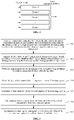
- FIG. 4 shows 7 logical threads and seven message queues. Multiple arrows on the left side represent multiple logical threads (the arrows are only schematic and do not represent an actual quantity of logical threads). Data packets in the seven logical threads are respectively written into the 7 message queues.
- the server further includes a message queue for receiving a data packet.
- the message queue is used for receiving a data packet transmitted by a client.
- Each logical thread reads a corresponding data packet from the message queue according to a thread identifier carried in the data packet.
- one client may transmit one or more data packets.
- logical operation types required by the multiple data packets may be the same or different.
- Data packets transmitted by one client may be assigned to different logical threads. Each logical thread may have data packets transmitted by different clients.
- step 303 the data packet obtained after the operation is read from the message queue according to the frame identifier, and the data packet obtained after the operation is synchronized to a client associated with the client.
- the data packet obtained after the operation is read from the message queue according to a timestamp sequence corresponding to the frame identifier, and the data packet obtained after the operation is synchronized to at least one associated client.
- the server reads data packets from the message queues, to prevent the order of picture frames corresponding to data packets received by a client from getting disrupted, the server reads data packets from the message queues frame by frame.
- the data packets are generated according to a timestamp sequence corresponding to the pictures, that is, a chronological order. Therefore, frame identifiers carried in the data packets are also arranged in the timestamp sequence.
- the server reads data packets from the message queues frame by frame, that is, completes the reading of data packets corresponding to the first picture frame before reading data packets corresponding to the second picture frame.
- the second picture frame is generated later than the first picture frame.
- the server performs logical operations on data packets corresponding to each picture frame, and transmits data packets obtained after the operations to an associated client.
- the associated client processes the data packets obtained after the operations to obtain the corresponding picture frame.
- data packets corresponding to one picture frame may be distributed in the message queues.
- the server needs to finish reading all data packets corresponding to the picture frame in each message queue. After the reading of the data packets corresponding to the picture frame in all the message queues is completed, the reading of the data packets corresponding to the picture frame is completed.
- the server synchronously transmits the read data packets to at least one associated client.
- the server further includes a packet transmission thread.
- the packet transmission thread is a single thread, to ensure that data of an application programming interface (API) for invoking and transmitting data packets is secure.
- API application programming interface
- An associated client is a client that has an association relationship with a client that transmits a data packet. Schematically, the client that transmits a data packet and the associated client participate in the same round of game.
- a user account into which the client that transmits a data packet has logged and a user account into which the associated client has logged have a friend relationship.
- the user account into which the client that transmits a data packet has logged and the user account into which the associated client has logged are in the same temporary chat message or in the same group chat.
- message queues are respectively assigned to corresponding logical threads determined according to logical operation types, to allow a server to write a data packet obtained after a logical thread operation into a message queue corresponding to each logical thread, to avoid a case that a write conflict of data packets occurs when multiple logical threads share one message queue.
- a quantity of message queues is reduced to reduce internal memory of the server occupied by message queues, thereby reducing the cost of message management.
- FIG. 5 is a flowchart of a data packet synchronization method according to another exemplary embodiment of the present disclosure. This embodiment is described by using an example in which the method is applied to the server 140 in the computer system 100 shown in FIG. 1 , where the server 140 is provided with k logical threads and k message queues, k being a positive integer.
- the logical threads have a one-to-one correspondence with the message queues.
- the logical threads are determined according to logical operation types.
- the method includes the following steps 501 to 507.
- step 501 a data packet transmitted by a client is received, the data packet carrying a thread identifier and a frame identifier, the thread identifier being added by the client according to a logical operation type required by the data packet, the frame identifier being used for identifying a picture frame triggering the data packet.
- step 502 the data packet is transmitted to an i th logical thread among the k logical threads according to the thread identifier, the i th logical thread corresponding to an i th message queue among the k message queues, i being a positive integer, i ⁇ k.
- the server assigns a data packet to a corresponding logical thread according to the thread identifier in the data packet. For example, a data packet carries a thread identifier of the i th logical thread, the server assigns the data packet to the i th logical thread. It may be understood that one client may transmit one or more data packets. When the client transmits multiple data packets, logical operation types required by the multiple data packets may be the same or different. Data packets transmitted by one client may be assigned to different logical threads. Each logical thread may have data packets transmitted by multiple clients.
- the server further includes a message queue for receiving a data packet.
- the message queue is used for receiving a data packet transmitted by a client.
- Each logical thread reads, according to a thread identifier, a corresponding data packet from the message queue.
- step 503 a logical operation is performed on the data packet by using the i th logical thread to obtain a data packet obtained after the operation.
- a game client is used as an example.
- a data packet transmitted by the game client to the server includes operation data.
- the operation data is used for recording an operation of a user in the game client.
- the operation data relates to a user controlling a virtual object to cast a skill.
- the data packet is assigned to the i th logical thread.
- the i th logical thread performs a logical operation according to data in the data packet.
- a logical operation performed by the i th logical thread relates to an action range and an action result after a virtual object casts a skill (whether the health points of a virtual object under the action of the skill are reduced and how many health points are reduced).
- the logical thread generates a data packet obtained after the operation by using data corresponding to the action range and the action result after the skill is cast.
- step 504 the data packet obtained after the operation is written into the i th message queue.
- one message queue may include one or more data packets transmitted by a target client.
- One message queue may include one or more data packets corresponding to one picture frame.
- step 505 a frame identifier of current consumption of the k message queues is determined.
- a consumption rule of the message queues is set on the server.
- the consumption rule specifies the i th message queue as a reference.
- a frame identifier that a data packet of current consumption of the i th message queue has is a frame identifier that data packets of current consumption of all message queues need to have, i being a positive integer, and i ⁇ k.
- the server includes eight message queues, that is, a first message queue, a second message queue, ..., and an eighth message queue.
- the consumption rule specifies the first message queue as a reference.
- a frame identifier that a data packet of current consumption of the first message queue is the frame identifier that data packets of current consumption of all message queues need to have.
- the frame identifier that the data packet of the current consumption of the first message is a frame identifier (the frame 1) corresponding to the first picture frame.
- the frame identifier of the current consumption is the frame 1.
- the remaining message queues also need to consume data packets with the frame identifier being the frame 1.
- step 506 a data packet corresponding to the frame identifier of the current consumption is read from the k message queues.
- the server reads the data packets with the frame identifier being the frame 1 from the k message queues.
- step 507 the data packet corresponding to the frame identifier of the current consumption is synchronized to the client associated with the client.
- the server further includes a packet transmission thread (shown by an arrow on the right side).
- the packet transmission thread is a single thread.
- the server transmits the data packet corresponding to the frame identifier of the current consumption to the packet transmission thread.
- the data packet corresponding to the frame identifier of the current consumption is synchronized to the at least one associated client by using the packet transmission thread.
- the packet transmission thread actively reads the data packet from the message queue, and synchronizes the read data packet to associated clients.
- a data packet A1 and a data packet C3 are written into a message queue 1.
- a data packet B2 is written into a message queue 2.
- a write sequence is: the data packet A1 ⁇ the data packet B2 ⁇ the data packet C3.
- Schematically, the data packet A1, the data packet C3, and the data packet B2 respectively belong to different picture frames.
- a packet transmission sequence of the packet transmission thread is: the data packet A1 ⁇ the data packet B2 ⁇ the data packet C3.
- message queues are respectively assigned according to corresponding logical threads for processing data packets, and when the data packets are written into the message queues corresponding to respective logical thread, a case that a write conflict occurs when multiple logical threads share one message queue is avoided.
- a quantity of message queues is reduced to reduce internal memory of the server occupied by message queues, thereby reducing the cost of message management.
- the thread identifier carried in the data packet is used to determine the logical thread for processing the data packet, thereby ensuring that a timing sequence disruption does not occur when the data packets obtained after the operation are subsequently written into the message queues.
- the frame identifier of current consumption of message queues are determined, so that all the message queues generally read data packets corresponding to picture frames having the same frame identifier, thereby ensuring that even if data packets of the same frame are not in the same message queue, the phenomenon of transmitting data packets across frames does not occur, to avoid a timing sequence disruption when the client receives the data packets.
- the method for reading data packets from message queues includes the following two manners.
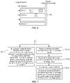
- step 506 may be replaced with the following step 5061a, as shown in FIG. 7 .
- step 5061a in response to that the frame identifier of the current consumption is the target frame identifier, data packets having the target frame identifier are sequentially read from the k message queues, until reading of all data packets having the target frame identifier in the k message queues is complete.
- the server inserts a cyclic barrier in each of the k message queues.
- the frame identifier corresponding to the picture frame is used as the cyclic barrier.
- a target frame identifier of a j th picture frame is inserted in the k message queues.
- the target frame identifier is used as the cyclic barrier, j being a positive integer.
- the target frame identifier is a frame identifier (a frame 3) of the third picture frame.
- the server reads the data packets with the frame identifier being the frame 3 from the first message queue.
- a cyclic barrier 11 and a cyclic barrier 12 are inserted in the message queues.
- the cyclic barrier 11 is used for reading data packets corresponding to the first picture frame from the message queues.
- the cyclic barrier 12 is used for reading data packets corresponding to the second picture frame from the message queues. After the reading of the data packets corresponding to the first picture frame in all the message queues is completed, data packets corresponding to the second picture frame in the message queues are read.
- the positions of the cyclic barriers shown in FIG. 8 are only schematic. In multiple message queues, the positions of the cyclic barriers corresponding to the same picture frame in the message queues may be the same or different. The position depends on a quantity of data packets belonging to the same picture frame in the message queue.
- the sequential reading from the k message queues may be: when reading of the data packets corresponding to the third picture frame in the first message queue is completed, data packets corresponding to the third picture frame are read from the second message queue; when reading of the data packets corresponding to the third picture frame in the second message queue is completed, data packets corresponding to the third picture frame are read from the third message queue; and this process is repeated until reading of data packets corresponding to the third picture frame in all the message queues is completed.
- Some data packets corresponding to the same picture frame are read from one message queue. When reading of these data packets is completed, some data packets corresponding to the picture frame are read from a next message queue. This process is repeated until reading of data packets corresponding to the picture frame in all the message queues is completed.
- the foregoing step 506 may be: reading the data packets corresponding to the frame identifier of the current consumption sequentially from the k message queues according to the duration thresholds respectively corresponding to the k message queues.
- the reading includes: replacing the foregoing step 506 with the following steps 5061b to 5063b, as shown in FIG. 7 :
- step 5061b a duration threshold corresponding to the n th message queue is acquired.
- the server separately inserts cyclic barriers in the k message queues.
- a frame identifier corresponding to the picture frame is used as a cyclic barrier.
- a target frame identifier of a j th picture frame is inserted in the k message queues.
- the target frame identifier is used as a cyclic barrier, j being a positive integer.
- the server when the server reads data packets from one message queue, the other message queues remain in a waiting state, especially the last message queue. Data packets in a message queue are read after the reading of the data packets in all message queues before the message queue is completed, but the server keeps writing data packets in the logical threads into the message queue, which tends to cause a congestion in the message queue. Therefore, the server sets a duration threshold for the message queue, and the k message queues have respective duration thresholds. The duration thresholds corresponding to the message queues may be equal or not equal.
- the duration threshold is obtained based on a consumption duration corresponding to the message queue.
- the consumption duration is an estimated duration of reading data packets corresponding to one picture frame from the message queue.
- the server estimates, according to a quantity of data packets with the same frame identifier in a message queue, a duration required for the message queue to consume the data packets of the frame, to obtain a consumption duration, so that the server determines the consumption duration to obtain a duration threshold.
- consumption durations corresponding to the same message queue may be equal or not equal.
- Multiple duration thresholds corresponding to the same message queue may be equal or not equal.
- Consumption durations corresponding to different message queues may be equal or not equal.
- Duration thresholds corresponding to different message queues may be equal or not equal.
- the duration threshold of each message queue is represented by a time slice 13 (the dash line in FIG. 9 ) obtained after division. That is, division is performed based on a consumption duration of the message queue consuming data packets corresponding to the same picture frame.
- the time slice is also referred to as a "quantum” or a "processor slice", which is a microscopic central processing unit (CPU) time period allocated by a time-division operating system to each running thread.
- the time slices 13 obtained after division may be equally divided or unequally divided.
- the positions of the time slices 13 in FIG. 9 are only schematic.
- the duration threshold corresponding to the n th message queue is 100 seconds.
- step 5062b a data packet having the target frame identifier is read from the n th message queue.
- the server reads data packets having the target frame identifier from the n th message queue within the duration threshold. For example, a duration threshold corresponding to the third message queue is 100 seconds. The server reads data packets corresponding to the third picture frame in the third message queue within 100 seconds.
- step 5063b in response to that a reading duration of the n th message queue exceeds the duration threshold corresponding to the n th message queue, reading of a data packet having the target frame identifier from an (n+1) th message queue is started.
- a countdown is performed during the reading of data packets in a message queue. For example, when the server starts to read the data packets corresponding to the third picture frame in the third message queue and starts a countdown of 100 seconds. When the countdown of 100 seconds ends, the server stops reading the data packets corresponding to the third picture frame in the third message queue, and starts to read data packets corresponding to the third picture frame from the fourth message queue.
- a count is performed during the reading of data packets in a message queue. For example, when the server starts to read the data packets corresponding to the third picture frame in the third message queue and starts a timer. When the count of the timer exceeds (or is equal to) 100 seconds, the server stops reading the data packets corresponding to the third picture frame in the third message queue, and starts to read the data packets corresponding to the third picture frame from the fourth message queue.
- duration thresholds corresponding to respective message queues are equal and are all 100 seconds.
- Data packets corresponding to the third picture frame in the first message queue are read within 100 seconds.
- a count of 100 seconds is performed again, and data packets corresponding to the third picture frame are read from the second message queue within 100 seconds.
- a count of 100 seconds is performed again, and data packets corresponding to the third picture frame are read from the third message queue within 100 seconds. This process is repeated.
- reading is started again from the first message queue. It is first determined whether the first message queue still has data packets corresponding to the third picture frame.
- the data packets corresponding to the third picture frame are read according to the duration threshold. If the first message queue does not have data packets corresponding to the third picture frame, data packets corresponding to the third picture frame are read from the second message queue. Similarly, it is to be determined whether the second message queue still has data packets corresponding to the third picture frame. This process is repeated, until reading of the data packets corresponding to the third picture frame in all the message queues is completed.
- a frame identifier is used as a cyclic barrier, so that when a server reads data packets belonging to the same picture frame in message queues, reading of data packets corresponding to one picture frame needs to be completed before data packets corresponding to a next picture frame are read, thereby avoiding transmission of data packets across frames.
- the consumption durations corresponding to each message queue are divided, so that each time the server only reads some data packets belonging to the same picture frame in each message queue, to prevent a latter message queue from waiting an excessively long time, thereby avoiding congestion because data packets are continuously written into the message queues.
- some data packets carry a large amount of data.
- a client receives the data packets, a large amount of resources needs to be consumed to load the data packets.
- a game client is used as an example.
- a terminal used by a user is a smartphone.
- the user When playing an MMORPG game on the smartphone, the user needs to use a network, for example, a Wireless Fidelity (Wi-Fi) network or a mobile communication network (network traffic provided by a network operator) in wireless networks.
- Wi-Fi Wireless Fidelity
- a mobile communication network network traffic provided by a network operator
- a mobile communication network is used as an example. If a data packet includes a larger amount of data, a larger amount of network traffic needs to be consumed. Therefore, to avoid consuming a large amount of network traffic, data included in data packets is filtered.
- a client is limited by its own field of view, and only a small portion of virtual objects in the field of view is displayed as models. For example, there are 80 virtual objects in the field of view. The user can only see complete models of 10 virtual objects, and only nicknames (or user accounts) are displayed for the remaining 70 virtual objects. The client displays the nicknames and health points of the 70 virtual objects but does not display special effects. Since special effects are not displayed, data packets related to skills of the virtual objects do not need to be transmitted to the associated clients.
- filtering data packets is performed in three levels.
- the filtering includes the following steps, as shown in FIG. 10 .
- step 210 field of view of the picture frame identified by the frame identifier of the current consumption is divided according to first position coordinates, to obtain m field of view areas, m being a positive integer.
- the server stores first position coordinates of a first virtual object controlled by the client.
- the data packet corresponding to the frame identifier of the current consumption includes a first type data packet.
- the first type data packet carries second position coordinates of a second virtual object in a picture frame.
- the first type data packet is a combat packet.
- the combat packet includes data about a virtual object casting a skill, data about the virtual object participating in a battle, data about changing a skill or changing a weapon, and the like.
- step 220 in response to that the second position coordinates are not in one of the m field of view areas, the first type data packet is filtered out from the data packet corresponding to the frame identifier of the current consumption.
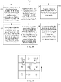
- the position coordinates of the second virtual object are not in the m field of view areas, and the first type data packet is filtered out from the data packet corresponding to the frame identifier of the current consumption. That is, the server transmits data packets corresponding to virtual objects in the m field of view areas to the client controlling the first virtual object. As shown in FIG. 11 , the value of m is 9.
- the field of view of a first virtual object 14 includes four virtual objects A, B, C, and D.
- the server transmits data packets corresponding to the virtual object A, the virtual object B, the virtual object C, and the virtual object D to a client controlling the first virtual object 14.
- the client displays the virtual object A, the virtual object B, the virtual object C, and the virtual object D. A nine-square grid is not displayed on the client.
- the position coordinates of the second virtual object are not in the first square, that is, a square corresponding to a sequence number 1 shown in FIG. 11 , in the nine-square grid.
- the server transmits data packets corresponding to other virtual objects in the first square to the client of the first virtual object 14.
- step 230 a field of view list corresponding to the m field of view areas is acquired, the field of view list including q second virtual objects in the m field of view areas, q being a positive integer.
- An upper quantity limit is set for virtual objects present in the m field of view areas. When there are excessive virtual objects in the field of view, a preset upper quantity limit may be used to limit the quantity of second virtual objects to be acquired.
- step 240 in response to that the second virtual object corresponding to the first type data packet is not included in the field of view list, the first type data packet is filtered out from the data packet corresponding to the frame identifier of the current consumption.
- m equals to 9.
- the server filters out the first type data packet from the data packets corresponding to the frame identifier of the current consumption. That is, the data packet corresponding to the second virtual object is filtered out, and the client controlling the first virtual object does not display the second virtual object.
- step 250 a position relationship between the first position coordinates and the second position coordinates is acquired.
- step 260 in response to that the position relationship meets a preset condition, the first type data packet is filtered out from the data packet corresponding to the frame identifier of the current consumption.
- the preset condition includes at least one of the following conditions:
- the first virtual object 14 faces a direction indicated by the arrow.
- the virtual object A and the virtual object B are located in front of the first virtual object.
- the virtual object C and the virtual object D are located behind the first virtual object 14.
- the virtual object D is the second virtual object.
- the distance between the virtual object D and the first virtual object 14 is greater than the distance threshold.
- the first type data packet is filtered out from the data packet corresponding to the frame identifier of the current consumption. That is, the client corresponding to the first virtual object 14 does not display the virtual object D.
- the virtual object C is the second virtual object.
- the virtual object C is located outside the field of view of the first virtual object 14.
- the first type data packet is filtered out from the data packet corresponding to the frame identifier of the current consumption. That is, the client corresponding to the first virtual object 14 does not display the virtual object D.
- the models and names of the virtual object C and the virtual object D are not displayed on the client corresponding to the first virtual object 14, and activities of interaction (for example, mutual attacks) between the virtual object C and the virtual object D are not displayed on the client either.
- the screen is a display screen triggered after the client receives the data packets with the first type data packet filtered out.
- a limited quantity of virtual objects are displayed on the screen.
- the screen is formed by the filed of view of the client controlling the first virtual object.
- a finer image model is displayed for a virtual object 21 closer to the first virtual object, and schematic image models are displayed for a virtual object 22 and a virtual object 23 farther away from the first virtual object, thereby reducing resources that need to be consumed when the client loads data packets.
- the data packet corresponding to the frame identifier of current consumption is filtered out to reduce data included in data packets to be synchronized to an associated client, so that resources consumed by the client can be reduced when the client loads the data packet obtained after filtering.
- the three levels of filtering may be separately implemented, or any two of the three levels of filtering may be combined for implementation, or all the three levels of filtering may be implemented.
- a data packet includes some data too important to be filtered out.
- the client is instructed to reduce a transmission frequency to reduce resources consumed when the client loads data packets.
- the data packet corresponding to the frame identifier of the current consumption further includes a second type data packet, and the second type data packet carries an attribute parameter of a virtual object.
- the second type data packet is an attribute data packet is used for description.
- the attribute parameter includes at least one of: data indicating health points, data indicating energy points, data indicating magic points, and data indicating attack power of a virtual object.
- the client In response to that the attribute parameter remains unchanged, the client is instructed to reduce the transmission frequency of the second type data packet.
- the server sets a dirty flag for the attribute parameter.
- the dirty flag is used to determine whether the attribute parameter of the virtual object is changed. For example, the dirty flag is checked at intervals of 500 milliseconds. If the dirty flag remains unchanged, it indicates that the second type data packet remains unchanged, and the server does not transmit a second type data packet to the client. If the dirty flag is changed, it indicates that the second type data packet is changed, and the server transmits the second type data packet to the client and sets a dirty flag again for the attribute parameter corresponding to the second type data packet.
- change of the dirty flag is used to determine whether the attribute parameter is changed, so that when the attribute parameter remains unchanged, the transmission frequency of the second type data packet is reduced, thereby reducing resources consumed when the client loads the second type data packet.
- for the step of cropping the first type data packet or transmitting the first type data packet with a reduced frequency may include performing filtering by using a logical thread and then writing the first type data packet into a message queue, or reading the first type data packet from a message queue and performing filtering on the read data packet.
- the overall procedure of the data packet synchronization method includes the following procedures.
- Multiple logical threads are provided in a server.
- the logical threads are used for performing a logical operation according to a data packet transmitted by a client.
- a game is used as an example.
- Each logical thread in the server is used for performing a game logical operation.
- the server assigns a message queue to each logical thread.
- Clients participating in the game generate a large number of data packets.
- the clients transmit data packets corresponding to one virtual environment picture frame to the server.
- the server writes data packets corresponding to the virtual environment picture frame into message queues according to thread identifiers carried in the data packets.
- the server When receiving the data packets, the server further records a receiving order of the data packets, and writes the data packets into the message queues according to the receiving order. That is, an order of data packets written into the same message queue is fixed.
- the server inserts a frame identifier of each virtual environment picture frame into the message queues as the cyclic barrier.
- the server specifies one message queue to consume a data packet of a frame.
- the server specifies the first message queue to consume a data packet corresponding to an i th virtual environment picture frame, and uses an identifier of the i th frame as a cyclic barrier.
- the server reads the data packet corresponding to the i th virtual environment picture frame, performs a game logical operation according to the data packet, and transmits the data packet obtained after the operation to clients.
- the server reads the second message queue, performs a game logical operation on a data packet located in front of the cyclic barrier in the second message queue, and transmits a data packet obtained after the operation to the clients. This process is repeated, until reading of data packets corresponding to the i th virtual environment picture frame in all the message queues is completed.
- data packets corresponding to an (i+1) th virtual environment picture frame are read.
- a manner of reading the data packets corresponding to the (i+1) th virtual environment picture frame is the same as that of reading the data packets corresponding to the i th virtual environment picture frame.
- the server consumes data packets in one message queue
- the other message queues are in a waiting state.
- the reading of the data packets belonging to the same picture frame in all the message queues in front needs to be completed before data packets in the last message queue can be read.
- data packets transmitted by the clients are continuously written into the message queues, which tends to cause a congestion in the message queues.
- the server allocates a time slice to a message queue.
- the time slice has a corresponding estimated duration for the message queue to consume a data packet of one virtual environment picture frame.
- the server divides the time slice of the message queue to obtain at least two time slices obtained after division of one message queue. The durations of the time slices obtained after division may be equal or not equal.
- the server reads the data packets corresponding to the i th virtual environment picture frame according to the durations of the time slices obtained after division. For example, a time slice obtained after division of the first message queue has a duration of 60 seconds, and a time slice obtained after division of the second message queue has a duration of 100 seconds.
- the server uses the 60 seconds to read data packets corresponding to the i th virtual environment picture frame in the first message queue.
- the server uses the 100 seconds to read data packets corresponding to the i th virtual environment picture frame in the second message queue.
- the data packets corresponding to the i th virtual environment picture frame in the first message queue may be completely read or partially read.
- the data packets corresponding to the i th virtual environment picture frame in the second message queue may be completely read or partially read.
- the server does not complete reading the data packets corresponding to the i th virtual environment picture frame in the first message queue within 60 seconds, when traversing to the first message queue again, the server continues to read the i th virtual environment picture frame.
- a message queue is assigned to each logical thread, so that a quantity of message queues is reduced, and the cost of message management is reduced.
- a cyclic barrier is inserted in the message queues, thereby avoiding transmission of data packets across frames.
- FIG. 13 is a structural block diagram of a data packet synchronization apparatus according to an exemplary embodiment of the present disclosure.
- the apparatus includes:
- the apparatus includes a transmission module 1340 and a processing module 1350.
- the transmission module 1340 is configured to transmit the data packet to an i th logical thread among the k logical threads according to the thread identifier, the i th logical thread corresponding to an i th message queue among the k message queues, i being a positive integer, i ⁇ k.
- the processing module 1350 is configured to perform the logical operation on the data packet by using the i th logical thread to obtain the data packet obtained after the operation.
- the write module 1320 is configured to write the data packet obtained after the operation into the i th message queue.
- the processing module 1350 is configured to determine a frame identifier of current consumption of the k message queues
- a data packet corresponding to a target frame identifier is written into the k message queues; and the read module 1330 is configured to: in response to that the frame identifier of the current consumption is the target frame identifier, sequentially read a data packet having the target frame identifier from the k message queues, until reading of all data packets having the target frame identifier in the k message queues is completed.
- a data packet corresponding to a target frame identifier is written into the k message queues, and the k message queues correspond to respective duration thresholds; and the processing module 1350 is configured to read the data packet corresponding to the frame identifier of the current consumption sequentially from the k message queues according to the duration thresholds respectively corresponding to the k message queues, and for an n th message queue in the k message queues, the processing module 1350 is configured to: acquire a duration threshold corresponding to the n th message queue, n being a positive integer, n ⁇ k; read a data packet having the target frame identifier from the n th message queue; and in response to that a reading duration of the n th message queue exceeds the duration threshold corresponding to the n th message queue, start to read a data packet having the target frame identifier from an (n+1) th message queue.
- the duration threshold is obtained by using a consumption duration corresponding to the message queue.
- the consumption duration is an estimated duration of reading a data packet corresponding to one picture frame from the message queue.
- the data packet corresponding to the frame identifier of the current consumption includes a first type data packet, and the first type data packet carries second position coordinates of a second virtual object in a picture frame; and the processing module 1350 is configured to: divide a field of view of the picture frame identified by the frame identifier of the current consumption according to first position coordinates, to obtain m field of view areas, m being a positive integer; and in response to that the second position coordinates are not in one of the m field of view areas, filter out the first type data packet from the data packet corresponding to the frame identifier of the current consumption.
- the processing module 1350 is configured to: acquire a field of view list corresponding to the m field of view areas, the field of view list including q second virtual objects in the m field of view areas, q being a positive integer; and in response to that the second virtual object corresponding to the first type data packet is not included in the field of view list, filter out the first type data packet from the data packet corresponding to the frame identifier of the current consumption.
- the server stores first position coordinates of a first virtual object controlled by the client
- the processing module 1350 is configured to: acquire a position relationship between the first position coordinates and the second position coordinates; and in response to that the position relationship meets a preset condition, filter out the first type data packet from the data packet corresponding to the frame identifier of the current consumption.
- the preset condition includes at least one of the following conditions:
- the data packet corresponding to the frame identifier of the current consumption includes a second type data packet, and the second type data packet carries an attribute parameter of a virtual object; and the processing module 1350 is configured to: in response to that the attribute parameter remains unchanged, instruct the client to reduce the transmission frequency of an attribute data packet.
- the transmission module 1330 is configured to: transmit the data packet corresponding to the frame identifier of the current consumption to a packet transmission thread; and synchronize the data packet to the client associated with the client by using the packet transmission thread.
- corresponding message queues are assigned to logical threads determined according to logical operation types, to allow a user to write a data packet obtained after a logical thread operation into a message queue corresponding to each logical thread, to avoid a case that a write conflict of data packets occurs when multiple threads share one message queue.
- a quantity of message queues is reduced to reduce internal memory of the server occupied by message queues, thereby reducing the cost of message management.
- Thread identifiers carried in the data packets are used to determine the logical threads for processing the data packets, thereby ensuring that the problem of a timing sequence error does not occur when the data packets obtained after the operation are subsequently written into the message queues.
- Frame identifiers of current consumption of message queues are determined, so that all the message queues generally read data packets corresponding to picture frames having the same frame identifier, thereby ensuring that even if data packets of the same frame are not in the same message queue, the phenomenon of transmitting data packets across frames does not occur, to avoid a timing sequence error when the client receives the data packets.
- a frame identifier is used as a cyclic barrier, so that when a server reads data packets belonging to the same picture frame in message queues, and reading of data packets corresponding to one picture frame needs to be completed before data packets corresponding to a next picture frame can be read, thereby avoiding transmission of data packets across frames.
- the consumption durations corresponding to the message queues are divided, so that each time the server only reads some data packets belonging to the same picture frame in each message queue, to prevent a message queue near the end from waiting an excessively long time, thereby avoiding a phenomenon of a congestion because data packets are written into the message queues.
- a data packet corresponding to a frame identifier of current consumption is filtered to reduce data included in a data packet to be synchronized to an associated client, so that resources consumed by the client when the client loads the data packet obtained after filtering can be reduced.
- a change in a dirty flag is used to determine whether an attribute parameter has changed, so that when the attribute parameter remains unchanged, a transmission frequency of a second type data packet is reduced, thereby reducing resources that need to be consumed when a client loads a second type data packet.
- the data packet synchronization apparatus For the foregoing data packet synchronization apparatus according to the embodiments, only division of the foregoing functional modules is used as an example for description. In the practical application, the functions may be allocated to and completed by different function modules according to requirements. That is, an internal structure of the device is divided into different functional modules, to complete all or some of the functions described above.
- the data packet synchronization apparatus according to the foregoing embodiment belongs to the same conception as the embodiment of the data packet synchronization method. For a specific implementation process thereof, reference may be made to the method embodiment. Details are not described herein again.
- FIG. 14 is a schematic structural diagram of a server according to an exemplary embodiment of the present disclosure.
- the server may be the server 140 in the computer system 100 shown in FIG. 1 .
- the server 140 includes a central processing unit (CPU) 1401, a system memory 1404 including a random access memory (RAM) 1402 and a read-only memory (ROM) 1403, and a system bus 1405 connecting the system memory 1404 and the CPU 1401.
- the server 140 further includes a basic input/output (I/O) system 1406 assisting in transmitting information between components in the computer, and a mass storage device 1407 configured to store an operating system 1413, an application 1414, and another program module 1415.
- CPU central processing unit
- system memory 1404 including a random access memory (RAM) 1402 and a read-only memory (ROM) 1403
- system bus 1405 connecting the system memory 1404 and the CPU 1401.
- the server 140 further includes a basic input/output (I/O) system 1406 assisting in transmitting information between components in the computer, and a mass storage device 1407 configured to store an operating system 1413, an application 1414, and another program module 1415.
- I/O basic input/output
- the basic I/O system 1406 includes a display 1408 configured to display information and an input device 1409 such as a mouse or a keyboard that is used for inputting information by a user.
- the display 1408 and the input device 1409 are both connected to the CPU 1401 by using an input/output controller 1410 connected to the system bus 1405.
- the basic I/O system 1406 may further include the input/output controller 1410 to be configured to receive and process inputs from multiple other devices such as a keyboard, a mouse, and an electronic stylus.
- the input/output controller 1410 further provides an output to a display screen, a printer, or another type of output device.
- the mass storage device 1407 is connected to the CPU 1401 by using a mass storage controller (not shown) connected to the system bus 1405.
- the mass storage device 1407 and a computer-readable medium associated with the large-capacity storage device provide non-volatile storage to the server 140. That is, the mass storage device 1407 may include the computer-readable medium (not shown) such as a hard disk or a Compact Disc Read-Only Memory (CD-ROM) drive.
- CD-ROM Compact Disc Read-Only Memory
- the computer-readable medium may include a computer storage medium and a communication medium.
- the computer storage medium includes volatile and non-volatile media, and removable and non-removable media implemented by using any method or technology used for storing information such as computer-readable instructions, data structures, program modules, or other data.
- the computer storage medium includes a RAM, a ROM, an erasable programmable ROM (EPROM), an electrically erasable programmable ROM (EEPROM), a flash memory or another solid-state memory technology, a CD-ROM, a digital versatile disc (DVD) or a solid state drive (SSD), another optical storage, a magnetic cassette, a magnetic tape, a magnetic disk memory, or another magnetic storage device.
- the RAM may include a resistance random access memory (ReRAM) and a dynamic random access memory (DRAM).
- ReRAM resistance random access memory
- DRAM dynamic random access memory
- the server 140 may further be connected, through a network such as the Internet, to a remote computer on the network and run. That is, the server 140 may be connected to a network 1412 by using a network interface unit 1411 connected to the system bus 1405, or may be connected to another type of network or a remote computer system (not shown) by using a network interface unit 1411.
- the memory further includes one or more programs.
- the one or more programs are stored in the memory and configured to be executed by the CPU.
- a computer device in an optional embodiment, includes a processor and a memory.
- the memory stores at least one instruction, at least one program, a code set or an instruction set.
- the at least one instruction, the at least one program, the code set, or the instruction set is loaded or executed by the processor to implement the data packet synchronization method in the foregoing aspects.
- a computer-readable storage medium stores at least one instruction, at least one program, a code set or an instruction set.
- the at least one instruction, the at least one program, the code set, or the instruction set is loaded or executed by the processor to implement the data packet synchronization method in the foregoing aspects.
- the computer-readable storage medium may include: a read-only memory (ROM), a random access memory (RAM), a solid state drive (SSD), an optical disc, or the like.
- the RAM may include a resistance random access memory (ReRAM) and a dynamic random access memory (DRAM).
- ReRAM resistance random access memory
- DRAM dynamic random access memory
- An embodiment of the present disclosure further provides a computer program product or a computer program.
- the computer program product or the computer program includes computer instructions, and the computer instructions are stored in a computer-readable storage medium.
- the processor of the computer device reads the computer instructions from the computer-readable storage medium, and the processor executes the computer instructions, to cause the computer device to perform the foregoing data packet synchronization method.
- the program may be stored in a computer-readable storage medium.
- the above-mentioned storage medium may be a read-only memory (ROM), a magnetic disk, an optical disk, or the like.
Landscapes
- Engineering & Computer Science (AREA)
- Theoretical Computer Science (AREA)
- Software Systems (AREA)
- Multimedia (AREA)
- Physics & Mathematics (AREA)
- General Engineering & Computer Science (AREA)
- General Physics & Mathematics (AREA)
- Computer Hardware Design (AREA)
- Mathematical Physics (AREA)
- Data Exchanges In Wide-Area Networks (AREA)
Abstract
Description
- This application claims priority to
Chinese Patent Application No. 202010760504.9, entitled "DATA PACKET SYNCHRONIZATION METHOD AND APPARATUS, DEVICE, AND STORAGE MEDIUM" and filed with the National Intellectual Property Administration, PRC on July 31, 2020 - The present disclosure relates to the field of data communication, and in particular, to data packet synchronization.
- When a user plays a game on a game client, the game client generates a data packet according to an operation of the user and transmits the data packet to a server. The server performs a game logical operation according to the data packet and synchronizes the data packet obtained after the game logical operation to all game clients participating in the game.
- In the game, multiple game clients transmit data packets to the server simultaneously, and the server needs to transmit the calculated game logic to the game clients according to the order of the received data packets. To avoid wrong orders when the server synchronizing the calculated game logic to the game clients, a message queue is assigned to each game client participating in the game. The data packet generated by each game client is written into the message queue corresponding to the game client according to the order, so that the server reads the data packets of the game clients in a correct order.
- A data packet synchronization method and apparatus, a device, and a storage medium according to embodiments of the present disclosure. A corresponding message queue is assigned to each logical thread, thereby reducing internal memory occupied by message queues in a server. The technical solutions are as follows.
- According to an aspect of the present disclosure, a data packet synchronization method is provided, the method being applied to a server provided with k logical threads and k message queues, k being a positive integer, the logical threads having a one-to-one correspondence with the message queues, the logical threads being determined according to logical operation types, the method including:
- receiving a data packet transmitted by a client, the data packet carrying a thread identifier and a frame identifier, the thread identifier being added by the client according to a logical operation type required by the data packet, the frame identifier being used for identifying a picture frame triggering the data packet;
- transmitting the data packet to a logical thread corresponding to the thread identifier for a logical operation, and writing a data packet obtained after the operation into a message queue corresponding to the logical thread; and
- reading the data packet obtained after the operation from the message queue according to the frame identifier, and synchronizing the data packet obtained after the operation to a client associated with the client.
- According to another aspect of the present disclosure, a data packet synchronization apparatus is provided, the apparatus including:
- a receiving module, configured to receive a data packet transmitted by a client, the data packet carrying a thread identifier and a frame identifier, the thread identifier being added by the client according to a logical operation type required by the data packet, the frame identifier being used for identifying a picture frame triggering the data packet;
- a write module, configured to transmite the data packet to a logical thread corresponding to the thread identifier for a logical operation, and write a data packet obtained after the operation into a message queue corresponding to the logical thread; and
- a read module, configured to read the data packet obtained after the operation from the message queue according to the frame identifier, and synchronize the data packet obtained after the operation to a client associated with the client.
- According to another aspect of the present disclosure, a computer device is provided. The computer device includes a processor and a memory. The memory stores at least one instruction, at least one program, a code set or an instruction set. The at least one instruction, the at least one program, the code set, or the instruction set is loaded or executed by the processor to implement the data packet synchronization method in the foregoing aspects.
- According to another aspect of the present disclosure, a computer-readable storage medium is provided. The computer-readable storage medium stores a computer program. The computer program is used for performing the data packet synchronization method in the foregoing aspects.
- According to another aspect of the present disclosure, a computer program product or a computer program is provided. The computer program product or the computer program includes computer instructions. The computer instructions are stored in a computer-readable storage medium. The processor of the computer device reads the computer instructions from the computer-readable storage medium, and the processor executes the computer instructions, to cause the computer device to perform the data packet synchronization method in the foregoing aspects.
- The beneficial effects brought by the technical solutions according to the embodiments of the present disclosure are at least as follows.
- Corresponding message queues are assigned to logical threads determined according to logical operation types, to allow a server to write a data packet obtained after a logical thread operation into a message queue corresponding to each logical thread, to avoid a case that a write conflict of data packets occurs when multiple threads share one message queue. In addition, a quantity of message queues is reduced to reduce internal memory of the server occupied by message queues, thereby reducing the cost of message management.
-
-
FIG. 1 is a framework diagram of a computer system according to an exemplary embodiment of the present disclosure. -
FIG. 2 is a schematic diagram of a status synchronization technology according to an exemplary embodiment of the present disclosure. -
FIG. 3 is a flowchart of a data packet synchronization method according to an exemplary embodiment of the present disclosure. -
FIG. 4 is a schematic framework diagram of a data packet synchronization method according to an exemplary embodiment of the present disclosure. -
FIG. 5 is a flowchart of a data packet synchronization method according to another exemplary embodiment of the present disclosure. -
FIG. 6 is a schematic framework diagram of a data packet synchronization method according to another exemplary embodiment of the present disclosure. -
FIG. 7 is a flowchart of a data packet synchronization method according to another exemplary embodiment of the present disclosure. -
FIG. 8 is a schematic framework diagram of a data packet synchronization method according to another exemplary embodiment of the present disclosure. -
FIG. 9 is a schematic framework diagram of a data packet synchronization method according to another exemplary embodiment of the present disclosure. -
FIG. 10 is a flowchart of a data packet synchronization method according to another exemplary embodiment of the present disclosure. -
FIG. 11 is a schematic framework diagram of m field of view areas according to an exemplary embodiment of the present disclosure. -
FIG. 12 is a schematic diagram of a screen on a client according to an exemplary embodiment of the present disclosure. -
FIG. 13 is a structural block diagram of a data packet synchronization apparatus according to an exemplary embodiment of the present disclosure. -
FIG. 14 is a schematic structural diagram of a server according to an exemplary embodiment of the present disclosure. - To make the objectives, technical solutions, and advantages of the present disclosure clearer, the implementations of the present disclosure are further described below in detail with reference to the accompanying drawings.
- First, the terms involved in the embodiments of the present disclosure are introduced.
- Message Queue (MQ): An MQ is a communication mode between applications and is used for storing messages (or data). A message queue follows a first in, first out principle. For example, a
message 1 is written into the message queue before amessage 2. During message reading, themessage 1 is read before themessage 2. A message generator (message publisher) publishes a message into a message queue. A message consumer (an active message acquirer) acquires the message from the message queue. The generator and the consumer do not interfere with each other. - Cyclic barrier (CB): Under a multi-thread condition, multiple threads cooperate with each other to complete a task, and a cyclic barrier is required to perform coordination between the multiple threads, to avoid the problem of temporal confusion in the multiple threads. In the embodiments of the present disclosure, a frame identifier of one environment picture frame is used as a cyclic barrier. When message queues all read the same frame identifier (cyclic barrier), it indicates that reading of data packets corresponding to the picture frame is completed, and the message queues may read data packets corresponding to a next picture frame.
- Dirty flag: A dirty flag is used for identifying whether current data is consistent with original data. If the current data is inconsistent with the original data, the current data is recalculated and the dirty flag is changed from 0 to 1. A dirty flag (the dirty flag is 0) is set again for a result obtained after the calculation. If the current data is consistent with the original data, the dirty flag is kept as 1 to continue to use the original data (current data). The dirty flag being 0 represents that data remains unchanged. The dirty flag being 1 represents that data has changed. The embodiments of the present disclosure are described by using an example in which a dirty flag is set for an attribute parameter of a virtual object. The attribute parameter is data of a second type data packet (for example, an attribute data packet). Schematically, a dirty flag is set for health points of a virtual object. When the health points of the virtual object have changed (restored or reduced), the dirty flag is changed from 0 to 1. When the health points of the virtual object remain unchanged, the dirty flag remains 0.
- Cloud computing: Cloud computing refers to a delivery and use mode of IT infrastructure, where required resources are obtained through a network in an on-demand, easily expandable manner. General cloud computing refers to a delivery and use mode of services, where required services are obtained through a network in an on-demand, easily expandable manner. Such services may be IT services related to software and Internet or may be other services. Cloud computing is a product of developing and integrating conventional computer and network technologies such as grid computing, distributed computing, parallel computing, utility computing, network storage technologies, virtualization, and load balance.
- With the diverse development of the Internet, real-time data streams, and connection devices, and driven by requirements such as search services, social networks, mobile commerce, and opening and collaboration, cloud computing develops rapidly. Different from previous parallel distributed computing, the emergence of cloud computing conceptually promotes the revolutionary change of the entire Internet mode and enterprise management mode. The data packet synchronization method according to the embodiments of the present disclosure is applicable to a cloud server. A corresponding message queue is assigned to each logical thread. Therefore, when the cloud server reads data packets, an order of the data packets is not disrupted, so that the data packets are transmitted to clients in a correct order, thereby reducing the cost of message management.
-
FIG. 1 is a structural block diagram of a computer system according to an exemplary embodiment of the present disclosure. Thecomputer system 100 includes afirst terminal 120, aserver 140, and asecond terminal 160. - An application supporting a virtual environment is installed and run on the
first terminal 120. The application may be any one of a virtual reality application, a three-dimensional map application, a military simulation application, an FPS game, a MOBA game, a Massive Multiplayer Online Role-Playing Game (MMORPG), a multiplayer shooting survival game, a battle royale shooting game, a virtual reality (VR) application, and an augmented reality (AR) application. Thefirst terminal 120 is used by a first user, and the first user uses thefirst terminal 120 to control a first virtual object in the virtual environment to perform a movement. The movement includes, but is not limited to, at least one of body posture adjustment, walking, running, jumping, cycling, aiming, picking-up, casting a skill, changing a skin, or attacking another virtual object. Schematically, the first virtual object is a first virtual character, for example, a simulated character object or a cartoon character object. - The
first terminal 120 is connected to theserver 140 by using a wireless network or a wired network. - The
server 140 may be an independent physical server, or may be a server cluster or a distributed system formed by multiple physical servers, or may be a cloud server providing basic cloud computing services, such as a cloud service, a cloud database, cloud computing, a cloud function, cloud storage, a network service, cloud communication, a middleware service, a domain name service, a security service, a content delivery network (CDN), and a big data and artificial intelligence platform. Schematically, theserver 140 includes aprocessor 144 and amemory 142. Thememory 142 includes areceiving module 1421, acontrol module 1422, and atransmission module 1423. Thereceiving module 1421 is configured to receive a data packet transmitted by a client, for example, a data packet generated from an ith virtual environment picture frame. Thecontrol module 1422 is configured to read a data packet from a message queue. Thetransmission module 1423 is configured to transmit data packets to clients. Theserver 140 is further configured to provide a backend service, for example, an information storage service, to an application supporting a three-dimensional virtual environment. Optionally, theserver 140 takes on primary computing work, and thefirst terminal 120 and thesecond terminal 160 take on secondary computing work. Alternatively, theserver 140 takes on secondary computing work, and thefirst terminal 120 and thesecond terminal 160 take on primary computing work. Alternatively, collaborative computing is performed by using a distributed computing architecture among theserver 140, thefirst terminal 120, and thesecond terminal 160. - The
server 140 may use a synchronization technology to implement consistent picture representation of multiple clients. For example, the synchronization technology used by theserver 140 includes a status synchronization technology or a frame synchronization technology. The data packet synchronization method according to the embodiments of the present disclosure may be implemented based on the status synchronization technology. - In an optional embodiment based on
FIG. 1 , theserver 140 uses the status synchronization technology to synchronize with multiple clients. In the status synchronization technology, as shown inFIG. 2 , a combat logic is run on theserver 140. When a virtual object in a virtual environment undergoes a status change, theserver 140 transmits a status synchronization result to all clients, for example,clients 1 to 10. - In an example, the
client 1 transmits a request to theserver 140 for requesting avirtual object 1 to attack avirtual object 2. Theserver 140 determines whether thevirtual object 1 is capable of attacking thevirtual object 2 and determines the remaining health points of thevirtual object 2 when thevirtual object 1 performs an operation of attacking thevirtual object 2. Next, theserver 140 transmits the remaining health points of thevirtual object 2 to all the clients. All the clients update local data and interface representation according to the remaining health points of thevirtual object 2. - An application supporting a virtual environment is installed and run on the
second terminal 160. The application program may be any one of a virtual reality application, a three-dimensional map application, a military simulation application, an FPS game, a MOBA game, an MMORPG game, a multiplayer shooting survival game, a battle royale shooting game, a VR application, and an AR application. Thesecond terminal 160 is used by a second user, and the second user uses thesecond terminal 160 to control a second virtual object in the virtual environment to perform a movement. The movement includes, but is not limited to, at least one of body posture adjustment, walking, running, jumping, cycling, aiming, casting a skill, changing a skin, picking-up, or attacking another virtual object. Schematically, the second virtual object is a second virtual character, for example, a simulated character object or a cartoon character object. - Optionally, the first virtual character object and the second virtual character object are located in the same virtual environment. Optionally, the first virtual character object and the second virtual character object may belong to the same team, the same organization or the same side, have a friend relationship, or have a temporary communication permission. Optionally, the first virtual person and the second virtual object may belong to different sides, different teams or different organizations or may be enemies of each other.
- Optionally, the applications installed on the
first terminal 120 and thesecond terminal 160 are the same, or the applications installed on the two terminals are the same type of applications on different operating system platforms (Android or iOS). Thefirst terminal 120 may be generally one of multiple terminals, and thesecond terminal 160 may be generally one of multiple terminals. In this embodiment, only thefirst terminal 120 and thesecond terminal 160 are used as an example for description. Thefirst terminal 120 and thesecond terminal 160 are of the same or different device types. The device type includes at least one of a smartphone, a tablet computer, an e-book reader, a Moving Picture Experts Group Audio Layer III (MP3) player, a Moving Picture Experts Group Audio Layer IV (MP4) player, a laptop, and a desktop computer. The following embodiment is described by using an example that the terminal includes a smartphone. - A person skilled in the art may learn that there may be more or fewer terminals. For example, there may be only one terminal, or there may be dozens of or hundreds of terminals or more. The quantity and the device type of the terminals are not limited in the embodiments of the present disclosure.
-
FIG. 3 is a flowchart of a data packet synchronization method according to an exemplary embodiment of the present disclosure. This embodiment is described by using an example in which the method is applied to theserver 140 in thecomputer system 100 shown inFIG. 1 , theserver 140 is provided with k logical threads and k message queues, k being a positive integer. The logical threads have a one-to-one correspondence with the message queues. The logical threads are determined according to logical operation types. The method includes the followingsteps 301 to 303. - In
step 301, a data packet transmitted by a client is received, the data packet carrying a thread identifier and a frame identifier, the thread identifier being added by the client according to a logical operation type required by the data packet, the frame identifier being used for identifying a picture frame triggering the data packet. - Various clients are run on a terminal. The clients transmit data packets to a server.
- For example, the clients are game clients. When a user performs some operations on a game client, the game client generates a data packet according to the operations of the user and transmits the data packet to the server. It should be understood that the server is connected to multiple game clients. The multiple game clients may all transmit data packets to the server.
- Schematically, a data packet includes at least one of control data generated from an operation of a user, data corresponding to a change in an attribute of a virtual object, data corresponding to an object on which the operation acts (for example, an object being aimed at or attacked), data of an animation special effect, or data of a change in a virtual environment picture. The client adds a thread identifier to a data packet according to a type of a logical operation that needs to be performed on data in the data packet. Schematically, the type of the logical operation includes at least one of a skill logical operation, an attribute logical operation, a position logical operation, an operation logical operation, or an animation effect logical operation.
- Schematically, the data packet generated by the client includes various data. Different types of data require different types of logical threads for logical operations. In the embodiments of the present disclosure, a case where data in one data packet is of the same type, that is, requires the same type of logical operation is described as an example. The thread identifier is a serial number of a thread. For example, thread identifiers are a
thread 1, athread 2, ..., and a thread k, k being a positive integer. - Schematically, the client generates a data packet according to each picture frame. The data packet carries a frame identifier of the picture frame. The frame identifier is used for distinguishing different picture frames. The frame identifier is an identifier that the picture frame has in an arrangement in a time order. Schematically, the frame identifier is a sequence number of a frame. For example, frame identifiers are a frame 1 (the first frame), a frame 2 (the second frame), ..., a frame j (a jth frame), j being a positive integer.
- In
step 302, the data packet is transmitted to a logical thread corresponding to the thread identifier for a logical operation, and a data packet obtained after the operation is written into a message queue corresponding to the logical thread. - On reception of a data packet, the server needs to perform a logical operation according to data in the data packet. For example, the data in the data packet relates to a user controlling a virtual object (a virtual object controlled by the user in a game) to cast a skill. The server needs to perform a skill type logical operation on the data packet, that is, perform a skill type logical operation on the data packet by using a skill type logical thread. Therefore, the data packet carries a thread identifier about the skill type logical thread.
- Because a corresponding message queue is assigned to each logical thread, the logical thread directly writes a data packet obtained after the logical operation into the message queue corresponding to the logical thread.
-
FIG. 4 shows 7 logical threads and seven message queues. Multiple arrows on the left side represent multiple logical threads (the arrows are only schematic and do not represent an actual quantity of logical threads). Data packets in the seven logical threads are respectively written into the 7 message queues. - In some embodiments, the server further includes a message queue for receiving a data packet. The message queue is used for receiving a data packet transmitted by a client. Each logical thread reads a corresponding data packet from the message queue according to a thread identifier carried in the data packet.
- It may be understood that one client may transmit one or more data packets. When the client transmits multiple data packets, logical operation types required by the multiple data packets may be the same or different. Data packets transmitted by one client may be assigned to different logical threads. Each logical thread may have data packets transmitted by different clients.
- In
step 303, the data packet obtained after the operation is read from the message queue according to the frame identifier, and the data packet obtained after the operation is synchronized to a client associated with the client. - The data packet obtained after the operation is read from the message queue according to a timestamp sequence corresponding to the frame identifier, and the data packet obtained after the operation is synchronized to at least one associated client. When the server reads data packets from the message queues, to prevent the order of picture frames corresponding to data packets received by a client from getting disrupted, the server reads data packets from the message queues frame by frame. The data packets are generated according to a timestamp sequence corresponding to the pictures, that is, a chronological order. Therefore, frame identifiers carried in the data packets are also arranged in the timestamp sequence.
- Schematically, the server reads data packets from the message queues frame by frame, that is, completes the reading of data packets corresponding to the first picture frame before reading data packets corresponding to the second picture frame. The second picture frame is generated later than the first picture frame. The server performs logical operations on data packets corresponding to each picture frame, and transmits data packets obtained after the operations to an associated client. The associated client processes the data packets obtained after the operations to obtain the corresponding picture frame.
- It should be understood that because the message queues have a one-to-one correspondence with the logical threads, data packets corresponding to one picture frame may be distributed in the message queues. When reading data packets corresponding to one picture frame, the server needs to finish reading all data packets corresponding to the picture frame in each message queue. After the reading of the data packets corresponding to the picture frame in all the message queues is completed, the reading of the data packets corresponding to the picture frame is completed. The server synchronously transmits the read data packets to at least one associated client.
- In some embodiments, as shown in
FIG. 4 , the server further includes a packet transmission thread. The packet transmission thread is a single thread, to ensure that data of an application programming interface (API) for invoking and transmitting data packets is secure. - An associated client is a client that has an association relationship with a client that transmits a data packet. Schematically, the client that transmits a data packet and the associated client participate in the same round of game. In some embodiments, a user account into which the client that transmits a data packet has logged and a user account into which the associated client has logged have a friend relationship. The user account into which the client that transmits a data packet has logged and the user account into which the associated client has logged are in the same temporary chat message or in the same group chat.
- In summary, in the method according to this embodiment, message queues are respectively assigned to corresponding logical threads determined according to logical operation types, to allow a server to write a data packet obtained after a logical thread operation into a message queue corresponding to each logical thread, to avoid a case that a write conflict of data packets occurs when multiple logical threads share one message queue. In addition, a quantity of message queues is reduced to reduce internal memory of the server occupied by message queues, thereby reducing the cost of message management.
-
FIG. 5 is a flowchart of a data packet synchronization method according to another exemplary embodiment of the present disclosure. This embodiment is described by using an example in which the method is applied to theserver 140 in thecomputer system 100 shown inFIG. 1 , where theserver 140 is provided with k logical threads and k message queues, k being a positive integer. The logical threads have a one-to-one correspondence with the message queues. The logical threads are determined according to logical operation types. The method includes the followingsteps 501 to 507. - In
step 501, a data packet transmitted by a client is received, the data packet carrying a thread identifier and a frame identifier, the thread identifier being added by the client according to a logical operation type required by the data packet, the frame identifier being used for identifying a picture frame triggering the data packet. - In
step 502, the data packet is transmitted to an ith logical thread among the k logical threads according to the thread identifier, the ith logical thread corresponding to an ith message queue among the k message queues, i being a positive integer, i < k. - The server assigns a data packet to a corresponding logical thread according to the thread identifier in the data packet. For example, a data packet carries a thread identifier of the ith logical thread, the server assigns the data packet to the ith logical thread. It may be understood that one client may transmit one or more data packets. When the client transmits multiple data packets, logical operation types required by the multiple data packets may be the same or different. Data packets transmitted by one client may be assigned to different logical threads. Each logical thread may have data packets transmitted by multiple clients.
- In some embodiments, the server further includes a message queue for receiving a data packet. The message queue is used for receiving a data packet transmitted by a client. Each logical thread reads, according to a thread identifier, a corresponding data packet from the message queue.
- In
step 503, a logical operation is performed on the data packet by using the ith logical thread to obtain a data packet obtained after the operation. - Schematically, a game client is used as an example. A data packet transmitted by the game client to the server includes operation data. The operation data is used for recording an operation of a user in the game client. For example, the operation data relates to a user controlling a virtual object to cast a skill. The data packet is assigned to the ith logical thread. The ith logical thread performs a logical operation according to data in the data packet. For example, a logical operation performed by the ith logical thread relates to an action range and an action result after a virtual object casts a skill (whether the health points of a virtual object under the action of the skill are reduced and how many health points are reduced). The logical thread generates a data packet obtained after the operation by using data corresponding to the action range and the action result after the skill is cast.
- In
step 504, the data packet obtained after the operation is written into the ith message queue. - Because the message queues have a one-to-one correspondence with the logical threads, in the ith message queue corresponding to the ith logical thread, the server writes the data packet obtained after the operation into the ith message queue corresponding to the ith logical thread. It should be understood that one message queue may include one or more data packets transmitted by a target client. One message queue may include one or more data packets corresponding to one picture frame.
- In
step 505, a frame identifier of current consumption of the k message queues is determined. - Schematically, a consumption rule of the message queues is set on the server. The consumption rule specifies the ith message queue as a reference. A frame identifier that a data packet of current consumption of the ith message queue has is a frame identifier that data packets of current consumption of all message queues need to have, i being a positive integer, and i ≤ k. For example, the server includes eight message queues, that is, a first message queue, a second message queue, ..., and an eighth message queue. The consumption rule specifies the first message queue as a reference. A frame identifier that a data packet of current consumption of the first message queue is the frame identifier that data packets of current consumption of all message queues need to have. The frame identifier that the data packet of the current consumption of the first message is a frame identifier (the frame 1) corresponding to the first picture frame. The frame identifier of the current consumption is the
frame 1. The remaining message queues also need to consume data packets with the frame identifier being theframe 1. - In
step 506, a data packet corresponding to the frame identifier of the current consumption is read from the k message queues. - Schematically, according to the foregoing consumption rule, the server reads the data packets with the frame identifier being the
frame 1 from the k message queues. - In
step 507, the data packet corresponding to the frame identifier of the current consumption is synchronized to the client associated with the client. - Schematically, as shown in
FIG. 4 , the server further includes a packet transmission thread (shown by an arrow on the right side). The packet transmission thread is a single thread. The server transmits the data packet corresponding to the frame identifier of the current consumption to the packet transmission thread. The data packet corresponding to the frame identifier of the current consumption is synchronized to the at least one associated client by using the packet transmission thread. In some embodiments, the packet transmission thread actively reads the data packet from the message queue, and synchronizes the read data packet to associated clients. - As shown in
FIG. 6 , a data packet A1 and a data packet C3 are written into amessage queue 1. A data packet B2 is written into amessage queue 2. A write sequence is: the data packet A1→the data packet B2→the data packet C3. Schematically, the data packet A1, the data packet C3, and the data packet B2 respectively belong to different picture frames. A packet transmission sequence of the packet transmission thread is: the data packet A1→the data packet B2→the data packet C3. - In summary, in the method according to this embodiment, message queues are respectively assigned according to corresponding logical threads for processing data packets, and when the data packets are written into the message queues corresponding to respective logical thread, a case that a write conflict occurs when multiple logical threads share one message queue is avoided. In addition, a quantity of message queues is reduced to reduce internal memory of the server occupied by message queues, thereby reducing the cost of message management.
- The thread identifier carried in the data packet is used to determine the logical thread for processing the data packet, thereby ensuring that a timing sequence disruption does not occur when the data packets obtained after the operation are subsequently written into the message queues.
- The frame identifier of current consumption of message queues are determined, so that all the message queues generally read data packets corresponding to picture frames having the same frame identifier, thereby ensuring that even if data packets of the same frame are not in the same message queue, the phenomenon of transmitting data packets across frames does not occur, to avoid a timing sequence disruption when the client receives the data packets.
- In an optional embodiment based on
FIG. 5 , the method for reading data packets from message queues includes the following two manners. - 1. When reading of data packets corresponding to the same picture frame in one message queue is completed, data packets of the picture frame in a next message queue are read. This process is repeated until reading of data packets corresponding to the picture frame in all the message queues is completed.
- The foregoing
step 506 may be replaced with the followingstep 5061a, as shown inFIG. 7 . - In
step 5061a, in response to that the frame identifier of the current consumption is the target frame identifier, data packets having the target frame identifier are sequentially read from the k message queues, until reading of all data packets having the target frame identifier in the k message queues is complete. - To prevent data packets corresponding to the same picture frame from being transmitted across frames, the server inserts a cyclic barrier in each of the k message queues. Schematically, the frame identifier corresponding to the picture frame is used as the cyclic barrier. For example, a target frame identifier of a jth picture frame is inserted in the k message queues. The target frame identifier is used as the cyclic barrier, j being a positive integer.
- Schematically, the target frame identifier is a frame identifier (a frame 3) of the third picture frame. The server reads the data packets with the frame identifier being the
frame 3 from the first message queue. - Schematically, after reading of data packets corresponding to the third picture frame in the first message queue is completed, data packets corresponding to the third picture frame are read from the second message queue. As shown in
FIG. 8 , acyclic barrier 11 and acyclic barrier 12 are inserted in the message queues. Schematically, thecyclic barrier 11 is used for reading data packets corresponding to the first picture frame from the message queues. Thecyclic barrier 12 is used for reading data packets corresponding to the second picture frame from the message queues. After the reading of the data packets corresponding to the first picture frame in all the message queues is completed, data packets corresponding to the second picture frame in the message queues are read. The positions of the cyclic barriers shown inFIG. 8 are only schematic. In multiple message queues, the positions of the cyclic barriers corresponding to the same picture frame in the message queues may be the same or different. The position depends on a quantity of data packets belonging to the same picture frame in the message queue. - The sequential reading from the k message queues may be: when reading of the data packets corresponding to the third picture frame in the first message queue is completed, data packets corresponding to the third picture frame are read from the second message queue; when reading of the data packets corresponding to the third picture frame in the second message queue is completed, data packets corresponding to the third picture frame are read from the third message queue; and this process is repeated until reading of data packets corresponding to the third picture frame in all the message queues is completed.
- 2. Some data packets corresponding to the same picture frame are read from one message queue. When reading of these data packets is completed, some data packets corresponding to the picture frame are read from a next message queue. This process is repeated until reading of data packets corresponding to the picture frame in all the message queues is completed.
- The foregoing
step 506 may be: reading the data packets corresponding to the frame identifier of the current consumption sequentially from the k message queues according to the duration thresholds respectively corresponding to the k message queues. - For an nth message queue in the k message queues, the reading includes:
replacing the foregoingstep 506 with the followingsteps 5061b to 5063b, as shown inFIG. 7 :
Instep 5061b, a duration threshold corresponding to the nth message queue is acquired. - To prevent data packets corresponding to the same picture frame from being transmitted across frames, the server separately inserts cyclic barriers in the k message queues. Schematically, a frame identifier corresponding to the picture frame is used as a cyclic barrier. For example, a target frame identifier of a jth picture frame is inserted in the k message queues. The target frame identifier is used as a cyclic barrier, j being a positive integer.
- In addition, when the server reads data packets from one message queue, the other message queues remain in a waiting state, especially the last message queue. Data packets in a message queue are read after the reading of the data packets in all message queues before the message queue is completed, but the server keeps writing data packets in the logical threads into the message queue, which tends to cause a congestion in the message queue. Therefore, the server sets a duration threshold for the message queue, and the k message queues have respective duration thresholds. The duration thresholds corresponding to the message queues may be equal or not equal.
- The duration threshold is obtained based on a consumption duration corresponding to the message queue. The consumption duration is an estimated duration of reading data packets corresponding to one picture frame from the message queue. Schematically, the server estimates, according to a quantity of data packets with the same frame identifier in a message queue, a duration required for the message queue to consume the data packets of the frame, to obtain a consumption duration, so that the server determines the consumption duration to obtain a duration threshold. Schematically, consumption durations corresponding to the same message queue may be equal or not equal. Multiple duration thresholds corresponding to the same message queue may be equal or not equal. Consumption durations corresponding to different message queues may be equal or not equal. Duration thresholds corresponding to different message queues may be equal or not equal.
- As shown in
FIG. 9 , the duration threshold of each message queue is represented by a time slice 13 (the dash line inFIG. 9 ) obtained after division. That is, division is performed based on a consumption duration of the message queue consuming data packets corresponding to the same picture frame. The time slice is also referred to as a "quantum" or a "processor slice", which is a microscopic central processing unit (CPU) time period allocated by a time-division operating system to each running thread. The time slices 13 obtained after division may be equally divided or unequally divided. The positions of thetime slices 13 inFIG. 9 are only schematic. - Schematically, the duration threshold corresponding to the nth message queue is 100 seconds.
- In
step 5062b, a data packet having the target frame identifier is read from the nth message queue. - The server reads data packets having the target frame identifier from the nth message queue within the duration threshold. For example, a duration threshold corresponding to the third message queue is 100 seconds. The server reads data packets corresponding to the third picture frame in the third message queue within 100 seconds.
- In
step 5063b, in response to that a reading duration of the nth message queue exceeds the duration threshold corresponding to the nth message queue, reading of a data packet having the target frame identifier from an (n+1)th message queue is started. - Schematically, a countdown is performed during the reading of data packets in a message queue. For example, when the server starts to read the data packets corresponding to the third picture frame in the third message queue and starts a countdown of 100 seconds. When the countdown of 100 seconds ends, the server stops reading the data packets corresponding to the third picture frame in the third message queue, and starts to read data packets corresponding to the third picture frame from the fourth message queue.
- Schematically, a count is performed during the reading of data packets in a message queue. For example, when the server starts to read the data packets corresponding to the third picture frame in the third message queue and starts a timer. When the count of the timer exceeds (or is equal to) 100 seconds, the server stops reading the data packets corresponding to the third picture frame in the third message queue, and starts to read the data packets corresponding to the third picture frame from the fourth message queue.
- Schematically, duration thresholds corresponding to respective message queues are equal and are all 100 seconds. Data packets corresponding to the third picture frame in the first message queue are read within 100 seconds. Next, a count of 100 seconds is performed again, and data packets corresponding to the third picture frame are read from the second message queue within 100 seconds. Next, a count of 100 seconds is performed again, and data packets corresponding to the third picture frame are read from the third message queue within 100 seconds. This process is repeated. After reading of data packets within 100 seconds in a kth message queue is performed, reading is started again from the first message queue. It is first determined whether the first message queue still has data packets corresponding to the third picture frame. If the first message queue has data packets corresponding to the third picture frame, the data packets corresponding to the third picture frame are read according to the duration threshold. If the first message queue does not have data packets corresponding to the third picture frame, data packets corresponding to the third picture frame are read from the second message queue. Similarly, it is to be determined whether the second message queue still has data packets corresponding to the third picture frame. This process is repeated, until reading of the data packets corresponding to the third picture frame in all the message queues is completed.
- In summary, in the method according to this embodiment, a frame identifier is used as a cyclic barrier, so that when a server reads data packets belonging to the same picture frame in message queues, reading of data packets corresponding to one picture frame needs to be completed before data packets corresponding to a next picture frame are read, thereby avoiding transmission of data packets across frames.
- The consumption durations corresponding to each message queue are divided, so that each time the server only reads some data packets belonging to the same picture frame in each message queue, to prevent a latter message queue from waiting an excessively long time, thereby avoiding congestion because data packets are continuously written into the message queues.
- Based on the foregoing packet generation mechanism, some data packets carry a large amount of data. As a result, when a client receives the data packets, a large amount of resources needs to be consumed to load the data packets. A game client is used as an example. A terminal used by a user is a smartphone. When playing an MMORPG game on the smartphone, the user needs to use a network, for example, a Wireless Fidelity (Wi-Fi) network or a mobile communication network (network traffic provided by a network operator) in wireless networks. A mobile communication network is used as an example. If a data packet includes a larger amount of data, a larger amount of network traffic needs to be consumed. Therefore, to avoid consuming a large amount of network traffic, data included in data packets is filtered.
- For example, a client is limited by its own field of view, and only a small portion of virtual objects in the field of view is displayed as models. For example, there are 80 virtual objects in the field of view. The user can only see complete models of 10 virtual objects, and only nicknames (or user accounts) are displayed for the remaining 70 virtual objects. The client displays the nicknames and health points of the 70 virtual objects but does not display special effects. Since special effects are not displayed, data packets related to skills of the virtual objects do not need to be transmitted to the associated clients.
- In the optional embodiment based on
FIG. 5 , filtering data packets is performed in three levels. The filtering includes the following steps, as shown inFIG. 10 . - In
step 210, field of view of the picture frame identified by the frame identifier of the current consumption is divided according to first position coordinates, to obtain m field of view areas, m being a positive integer. - The server stores first position coordinates of a first virtual object controlled by the client. The data packet corresponding to the frame identifier of the current consumption includes a first type data packet. The first type data packet carries second position coordinates of a second virtual object in a picture frame. Schematically, the first type data packet is a combat packet. The combat packet includes data about a virtual object casting a skill, data about the virtual object participating in a battle, data about changing a skill or changing a weapon, and the like.
- In
step 220, in response to that the second position coordinates are not in one of the m field of view areas, the first type data packet is filtered out from the data packet corresponding to the frame identifier of the current consumption. - Schematically, the position coordinates of the second virtual object are not in the m field of view areas, and the first type data packet is filtered out from the data packet corresponding to the frame identifier of the current consumption. That is, the server transmits data packets corresponding to virtual objects in the m field of view areas to the client controlling the first virtual object. As shown in
FIG. 11 , the value of m is 9. The field of view of a firstvirtual object 14 includes four virtual objects A, B, C, and D. The server transmits data packets corresponding to the virtual object A, the virtual object B, the virtual object C, and the virtual object D to a client controlling the firstvirtual object 14. The client displays the virtual object A, the virtual object B, the virtual object C, and the virtual object D. A nine-square grid is not displayed on the client. - In another example, the position coordinates of the second virtual object are not in the first square, that is, a square corresponding to a
sequence number 1 shown inFIG. 11 , in the nine-square grid. The server transmits data packets corresponding to other virtual objects in the first square to the client of the firstvirtual object 14. - In
step 230, a field of view list corresponding to the m field of view areas is acquired, the field of view list including q second virtual objects in the m field of view areas, q being a positive integer. - Multiple virtual objects may be present in the m field of view areas. However, all the multiple virtual objects present in the m field of view areas are not displayed on the client. An upper quantity limit is set for virtual objects present in the m field of view areas. When there are excessive virtual objects in the field of view, a preset upper quantity limit may be used to limit the quantity of second virtual objects to be acquired.
- In
step 240, in response to that the second virtual object corresponding to the first type data packet is not included in the field of view list, the first type data packet is filtered out from the data packet corresponding to the frame identifier of the current consumption. - Schematically, m equals to 9. When a second virtual object enters the nine-square grid field of view and the second virtual object is to be included in the field of view list, a quantity of second virtual objects exceeds the quantity specified in the field of view list, the server filters out the first type data packet from the data packets corresponding to the frame identifier of the current consumption. That is, the data packet corresponding to the second virtual object is filtered out, and the client controlling the first virtual object does not display the second virtual object.
- In
step 250, a position relationship between the first position coordinates and the second position coordinates is acquired. - In
step 260, in response to that the position relationship meets a preset condition, the first type data packet is filtered out from the data packet corresponding to the frame identifier of the current consumption. - Schematically, the preset condition includes at least one of the following conditions:
- a distance between the first virtual object and the second virtual object is greater than a distance threshold; and
- the second virtual object is outside a field of view of the first virtual object.
- As shown in
FIG. 11 , the firstvirtual object 14 faces a direction indicated by the arrow. The virtual object A and the virtual object B are located in front of the first virtual object. The virtual object C and the virtual object D are located behind the firstvirtual object 14. Schematically, the virtual object D is the second virtual object. The distance between the virtual object D and the firstvirtual object 14 is greater than the distance threshold. In this case, the first type data packet is filtered out from the data packet corresponding to the frame identifier of the current consumption. That is, the client corresponding to the firstvirtual object 14 does not display the virtual object D. Schematically, the virtual object C is the second virtual object. The virtual object C is located outside the field of view of the firstvirtual object 14. In this case, the first type data packet is filtered out from the data packet corresponding to the frame identifier of the current consumption. That is, the client corresponding to the firstvirtual object 14 does not display the virtual object D. Schematically, for the virtual object C and the virtual object D, the models and names of the virtual object C and the virtual object D are not displayed on the client corresponding to the firstvirtual object 14, and activities of interaction (for example, mutual attacks) between the virtual object C and the virtual object D are not displayed on the client either. - As shown in
FIG. 12 , the screen is a display screen triggered after the client receives the data packets with the first type data packet filtered out. A limited quantity of virtual objects are displayed on the screen. The screen is formed by the filed of view of the client controlling the first virtual object. Schematically, a finer image model is displayed for avirtual object 21 closer to the first virtual object, and schematic image models are displayed for a virtual object 22 and avirtual object 23 farther away from the first virtual object, thereby reducing resources that need to be consumed when the client loads data packets. - In summary, in the method according to this embodiment, the data packet corresponding to the frame identifier of current consumption is filtered out to reduce data included in data packets to be synchronized to an associated client, so that resources consumed by the client can be reduced when the client loads the data packet obtained after filtering.
- It should be understood that the three levels of filtering may be separately implemented, or any two of the three levels of filtering may be combined for implementation, or all the three levels of filtering may be implemented.
- In some embodiments, a data packet includes some data too important to be filtered out. In this case, the client is instructed to reduce a transmission frequency to reduce resources consumed when the client loads data packets.
- Schematically, the data packet corresponding to the frame identifier of the current consumption further includes a second type data packet, and the second type data packet carries an attribute parameter of a virtual object. An example in which the second type data packet is an attribute data packet is used for description. The attribute parameter includes at least one of: data indicating health points, data indicating energy points, data indicating magic points, and data indicating attack power of a virtual object.
- In response to that the attribute parameter remains unchanged, the client is instructed to reduce the transmission frequency of the second type data packet.
- Schematically, the server sets a dirty flag for the attribute parameter. The dirty flag is used to determine whether the attribute parameter of the virtual object is changed. For example, the dirty flag is checked at intervals of 500 milliseconds. If the dirty flag remains unchanged, it indicates that the second type data packet remains unchanged, and the server does not transmit a second type data packet to the client. If the dirty flag is changed, it indicates that the second type data packet is changed, and the server transmits the second type data packet to the client and sets a dirty flag again for the attribute parameter corresponding to the second type data packet.
- In summary, in the method according to this embodiment, change of the dirty flag is used to determine whether the attribute parameter is changed, so that when the attribute parameter remains unchanged, the transmission frequency of the second type data packet is reduced, thereby reducing resources consumed when the client loads the second type data packet.
- In some embodiments, for the step of cropping the first type data packet or transmitting the first type data packet with a reduced frequency may include performing filtering by using a logical thread and then writing the first type data packet into a message queue, or reading the first type data packet from a message queue and performing filtering on the read data packet.
- In an example, the overall procedure of the data packet synchronization method includes the following procedures.
- Multiple logical threads are provided in a server. The logical threads are used for performing a logical operation according to a data packet transmitted by a client.
- Schematically, a game is used as an example. Each logical thread in the server is used for performing a game logical operation. The server assigns a message queue to each logical thread. Clients participating in the game generate a large number of data packets. Schematically, the clients transmit data packets corresponding to one virtual environment picture frame to the server. The server writes data packets corresponding to the virtual environment picture frame into message queues according to thread identifiers carried in the data packets. When receiving the data packets, the server further records a receiving order of the data packets, and writes the data packets into the message queues according to the receiving order. That is, an order of data packets written into the same message queue is fixed.
- The server inserts a frame identifier of each virtual environment picture frame into the message queues as the cyclic barrier. The server specifies one message queue to consume a data packet of a frame. For example, the server specifies the first message queue to consume a data packet corresponding to an ith virtual environment picture frame, and uses an identifier of the ith frame as a cyclic barrier. Starting from the first message queue, the server reads the data packet corresponding to the ith virtual environment picture frame, performs a game logical operation according to the data packet, and transmits the data packet obtained after the operation to clients. Next, the server reads the second message queue, performs a game logical operation on a data packet located in front of the cyclic barrier in the second message queue, and transmits a data packet obtained after the operation to the clients. This process is repeated, until reading of data packets corresponding to the ith virtual environment picture frame in all the message queues is completed.
- After the reading of the data packets corresponding to the ith virtual environment picture frame is completed, data packets corresponding to an (i+1)th virtual environment picture frame are read. A manner of reading the data packets corresponding to the (i+1)th virtual environment picture frame is the same as that of reading the data packets corresponding to the ith virtual environment picture frame.
- Based on the foregoing transmission mechanism of data packets, when the server consumes data packets in one message queue, the other message queues are in a waiting state. For the last message queue, the reading of the data packets belonging to the same picture frame in all the message queues in front needs to be completed before data packets in the last message queue can be read. Meanwhile, data packets transmitted by the clients are continuously written into the message queues, which tends to cause a congestion in the message queues.
- In some embodiments, the server allocates a time slice to a message queue. The time slice has a corresponding estimated duration for the message queue to consume a data packet of one virtual environment picture frame. The server divides the time slice of the message queue to obtain at least two time slices obtained after division of one message queue. The durations of the time slices obtained after division may be equal or not equal.
- Schematically, starting from the first message queue, the server reads the data packets corresponding to the ith virtual environment picture frame according to the durations of the time slices obtained after division. For example, a time slice obtained after division of the first message queue has a duration of 60 seconds, and a time slice obtained after division of the second message queue has a duration of 100 seconds. Starting from the first message queue, the server uses the 60 seconds to read data packets corresponding to the ith virtual environment picture frame in the first message queue. When the duration of the time slice obtained after division reaches 0, the server uses the 100 seconds to read data packets corresponding to the ith virtual environment picture frame in the second message queue. Within the 60 seconds, the data packets corresponding to the ith virtual environment picture frame in the first message queue may be completely read or partially read. Similarly, within the 100 seconds, the data packets corresponding to the ith virtual environment picture frame in the second message queue may be completely read or partially read.
- Schematically, if the server does not complete reading the data packets corresponding to the ith virtual environment picture frame in the first message queue within 60 seconds, when traversing to the first message queue again, the server continues to read the ith virtual environment picture frame.
- In the foregoing manner, all message queues are cyclically traversed until the ith frame identifier has been read in all the message queues. It indicates that reading of the data packets corresponding to the ith virtual environment picture frame is completed, and the server uses the foregoing manner to read the data packets corresponding to the (i+1)th virtual environment picture frame.
- Through the method according to this embodiment, a message queue is assigned to each logical thread, so that a quantity of message queues is reduced, and the cost of message management is reduced. A cyclic barrier is inserted in the message queues, thereby avoiding transmission of data packets across frames.
-
FIG. 13 is a structural block diagram of a data packet synchronization apparatus according to an exemplary embodiment of the present disclosure. The apparatus includes: - a
receiving module 1310, configured to receive a data packet transmitted by a client, the data packet carrying a thread identifier and a frame identifier, the thread identifier being added by the client according to a logical operation type required by the data packet, the frame identifier being used for identifying a picture frame triggering the data packet; - a
write module 1320, configured to transmit the data packet to a logical thread corresponding to the thread identifier for a logical operation, and write a data packet obtained after the operation into a message queue corresponding to the logical thread; and - a
read module 1330, configured to read the data packet obtained after the operation from the message queue according to the frame identifier, and synchronize the data packet obtained after the operation to a client associated with the client. - In an optional embodiment, the apparatus includes a
transmission module 1340 and aprocessing module 1350. - The
transmission module 1340 is configured to transmit the data packet to an ith logical thread among the k logical threads according to the thread identifier, the ith logical thread corresponding to an ith message queue among the k message queues, i being a positive integer, i < k. - The
processing module 1350 is configured to perform the logical operation on the data packet by using the ith logical thread to obtain the data packet obtained after the operation. - The
write module 1320 is configured to write the data packet obtained after the operation into the ith message queue. - In an optional embodiment, the
processing module 1350 is configured to determine a frame identifier of current consumption of the k message queues; - the
read module 1330 is configured to read a data packet corresponding to the frame identifier of the current consumption from the k message queues; and - the
transmission module 1340 is configured to synchronize the data packet corresponding to the frame identifier of the current consumption to the client associated with the client. - In an optional embodiment, a data packet corresponding to a target frame identifier is written into the k message queues; and
theread module 1330 is configured to: in response to that the frame identifier of the current consumption is the target frame identifier, sequentially read a data packet having the target frame identifier from the k message queues, until reading of all data packets having the target frame identifier in the k message queues is completed. - In an optional embodiment, a data packet corresponding to a target frame identifier is written into the k message queues, and the k message queues correspond to respective duration thresholds; and
theprocessing module 1350 is configured to read the data packet corresponding to the frame identifier of the current consumption sequentially from the k message queues according to the duration thresholds respectively corresponding to the k message queues, and for an nth message queue in the k message queues, theprocessing module 1350 is configured to: acquire a duration threshold corresponding to the nth message queue, n being a positive integer, n ≤ k; read a data packet having the target frame identifier from the nth message queue; and in response to that a reading duration of the nth message queue exceeds the duration threshold corresponding to the nth message queue, start to read a data packet having the target frame identifier from an (n+1)th message queue. - In an optional embodiment, the duration threshold is obtained by using a consumption duration corresponding to the message queue. The consumption duration is an estimated duration of reading a data packet corresponding to one picture frame from the message queue.
- In an optional embodiment, the data packet corresponding to the frame identifier of the current consumption includes a first type data packet, and the first type data packet carries second position coordinates of a second virtual object in a picture frame; and
theprocessing module 1350 is configured to: divide a field of view of the picture frame identified by the frame identifier of the current consumption according to first position coordinates, to obtain m field of view areas, m being a positive integer; and in response to that the second position coordinates are not in one of the m field of view areas, filter out the first type data packet from the data packet corresponding to the frame identifier of the current consumption. - In an optional embodiment, the
processing module 1350 is configured to: acquire a field of view list corresponding to the m field of view areas, the field of view list including q second virtual objects in the m field of view areas, q being a positive integer; and in response to that the second virtual object corresponding to the first type data packet is not included in the field of view list, filter out the first type data packet from the data packet corresponding to the frame identifier of the current consumption. - In an optional embodiment, the server stores first position coordinates of a first virtual object controlled by the client, and the
processing module 1350 is configured to: acquire a position relationship between the first position coordinates and the second position coordinates; and in response to that the position relationship meets a preset condition, filter out the first type data packet from the data packet corresponding to the frame identifier of the current consumption. - In an optional embodiment, the preset condition includes at least one of the following conditions:
- a distance between the first virtual object and the second virtual object is greater than a distance threshold; or
- the second virtual object is outside a field of view of the first virtual object.
- In an optional embodiment, the data packet corresponding to the frame identifier of the current consumption includes a second type data packet, and the second type data packet carries an attribute parameter of a virtual object; and
theprocessing module 1350 is configured to: in response to that the attribute parameter remains unchanged, instruct the client to reduce the transmission frequency of an attribute data packet. - In an optional embodiment, the
transmission module 1330 is configured to: transmit the data packet corresponding to the frame identifier of the current consumption to a packet transmission thread; and synchronize the data packet to the client associated with the client by using the packet transmission thread. - In summary, for the apparatus according to this embodiment, corresponding message queues are assigned to logical threads determined according to logical operation types, to allow a user to write a data packet obtained after a logical thread operation into a message queue corresponding to each logical thread, to avoid a case that a write conflict of data packets occurs when multiple threads share one message queue. In addition, a quantity of message queues is reduced to reduce internal memory of the server occupied by message queues, thereby reducing the cost of message management.
- Thread identifiers carried in the data packets are used to determine the logical threads for processing the data packets, thereby ensuring that the problem of a timing sequence error does not occur when the data packets obtained after the operation are subsequently written into the message queues.
- Frame identifiers of current consumption of message queues are determined, so that all the message queues generally read data packets corresponding to picture frames having the same frame identifier, thereby ensuring that even if data packets of the same frame are not in the same message queue, the phenomenon of transmitting data packets across frames does not occur, to avoid a timing sequence error when the client receives the data packets.
- A frame identifier is used as a cyclic barrier, so that when a server reads data packets belonging to the same picture frame in message queues, and reading of data packets corresponding to one picture frame needs to be completed before data packets corresponding to a next picture frame can be read, thereby avoiding transmission of data packets across frames.
- The consumption durations corresponding to the message queues are divided, so that each time the server only reads some data packets belonging to the same picture frame in each message queue, to prevent a message queue near the end from waiting an excessively long time, thereby avoiding a phenomenon of a congestion because data packets are written into the message queues.
- A data packet corresponding to a frame identifier of current consumption is filtered to reduce data included in a data packet to be synchronized to an associated client, so that resources consumed by the client when the client loads the data packet obtained after filtering can be reduced.
- A change in a dirty flag is used to determine whether an attribute parameter has changed, so that when the attribute parameter remains unchanged, a transmission frequency of a second type data packet is reduced, thereby reducing resources that need to be consumed when a client loads a second type data packet.
- For the foregoing data packet synchronization apparatus according to the embodiments, only division of the foregoing functional modules is used as an example for description. In the practical application, the functions may be allocated to and completed by different function modules according to requirements. That is, an internal structure of the device is divided into different functional modules, to complete all or some of the functions described above. In addition, the data packet synchronization apparatus according to the foregoing embodiment belongs to the same conception as the embodiment of the data packet synchronization method. For a specific implementation process thereof, reference may be made to the method embodiment. Details are not described herein again.
-
FIG. 14 is a schematic structural diagram of a server according to an exemplary embodiment of the present disclosure. The server may be theserver 140 in thecomputer system 100 shown inFIG. 1 . - The
server 140 includes a central processing unit (CPU) 1401, asystem memory 1404 including a random access memory (RAM) 1402 and a read-only memory (ROM) 1403, and asystem bus 1405 connecting thesystem memory 1404 and theCPU 1401. Theserver 140 further includes a basic input/output (I/O)system 1406 assisting in transmitting information between components in the computer, and amass storage device 1407 configured to store anoperating system 1413, anapplication 1414, and anotherprogram module 1415. - The basic I/
O system 1406 includes adisplay 1408 configured to display information and aninput device 1409 such as a mouse or a keyboard that is used for inputting information by a user. Thedisplay 1408 and theinput device 1409 are both connected to theCPU 1401 by using an input/output controller 1410 connected to thesystem bus 1405. The basic I/O system 1406 may further include the input/output controller 1410 to be configured to receive and process inputs from multiple other devices such as a keyboard, a mouse, and an electronic stylus. Similarly, the input/output controller 1410 further provides an output to a display screen, a printer, or another type of output device. - The
mass storage device 1407 is connected to theCPU 1401 by using a mass storage controller (not shown) connected to thesystem bus 1405. Themass storage device 1407 and a computer-readable medium associated with the large-capacity storage device provide non-volatile storage to theserver 140. That is, themass storage device 1407 may include the computer-readable medium (not shown) such as a hard disk or a Compact Disc Read-Only Memory (CD-ROM) drive. - The computer-readable medium may include a computer storage medium and a communication medium. The computer storage medium includes volatile and non-volatile media, and removable and non-removable media implemented by using any method or technology used for storing information such as computer-readable instructions, data structures, program modules, or other data. The computer storage medium includes a RAM, a ROM, an erasable programmable ROM (EPROM), an electrically erasable programmable ROM (EEPROM), a flash memory or another solid-state memory technology, a CD-ROM, a digital versatile disc (DVD) or a solid state drive (SSD), another optical storage, a magnetic cassette, a magnetic tape, a magnetic disk memory, or another magnetic storage device. The RAM may include a resistance random access memory (ReRAM) and a dynamic random access memory (DRAM). Certainly, a person skilled in art can know that the computer storage medium is not limited to the foregoing several types. The
system memory 1404 and themass storage device 1407 may be collectively referred to as a memory. - According to the embodiments of the present disclosure, the
server 140 may further be connected, through a network such as the Internet, to a remote computer on the network and run. That is, theserver 140 may be connected to anetwork 1412 by using anetwork interface unit 1411 connected to thesystem bus 1405, or may be connected to another type of network or a remote computer system (not shown) by using anetwork interface unit 1411. - The memory further includes one or more programs. The one or more programs are stored in the memory and configured to be executed by the CPU.
- In an optional embodiment, a computer device is provided. The computer device includes a processor and a memory. The memory stores at least one instruction, at least one program, a code set or an instruction set. The at least one instruction, the at least one program, the code set, or the instruction set is loaded or executed by the processor to implement the data packet synchronization method in the foregoing aspects.
- In an optional embodiment, a computer-readable storage medium is provided. The storage medium stores at least one instruction, at least one program, a code set or an instruction set. The at least one instruction, the at least one program, the code set, or the instruction set is loaded or executed by the processor to implement the data packet synchronization method in the foregoing aspects.
- Optionally, the computer-readable storage medium may include: a read-only memory (ROM), a random access memory (RAM), a solid state drive (SSD), an optical disc, or the like. The RAM may include a resistance random access memory (ReRAM) and a dynamic random access memory (DRAM). The sequence numbers of the foregoing embodiments of the present disclosure are merely for description purpose but do not imply the preference among the embodiments.
- An embodiment of the present disclosure further provides a computer program product or a computer program. The computer program product or the computer program includes computer instructions, and the computer instructions are stored in a computer-readable storage medium. The processor of the computer device reads the computer instructions from the computer-readable storage medium, and the processor executes the computer instructions, to cause the computer device to perform the foregoing data packet synchronization method.
- A person of ordinary skill in the art may understand that all or some of the steps implementing the methods in the foregoing embodiments may be implemented by hardware or a program instructing relevant hardware. The program may be stored in a computer-readable storage medium. The above-mentioned storage medium may be a read-only memory (ROM), a magnetic disk, an optical disk, or the like.
- The foregoing descriptions are merely optional embodiments of the present disclosure, but are not intended to limit the present disclosure. Any modification, equivalent replacement, or improvement made within the spirit and principle of the present disclosure shall fall within the protection scope of the present disclosure.
Claims (16)
- A data packet synchronization method, the method being performed by a server provided with k logical threads and k message queues, k being a positive integer, the logical threads having a one-to-one correspondence with the message queues, the logical threads being determined according to logical operation types, the method comprising:receiving a data packet transmitted by a client, the data packet carrying a thread identifier and a frame identifier, the thread identifier being added by the client according to a logical operation type required by the data packet, the frame identifier being used for identifying a picture frame triggering the data packet;transmitting the data packet to a logical thread corresponding to the thread identifier for a logical operation, and writing a data packet obtained after the operation into a message queue corresponding to the logical thread; andreading the data packet obtained after the operation from the message queue according to the frame identifier, and synchronizing the data packet obtained after the operation to a client associated with the client.
- The method according to claim 1, wherein the transmitting the data packet to a logical thread corresponding to the thread identifier for a logical operation, and writing a data packet obtained after the operation into a message queue corresponding to the logical thread comprises:transmitting the data packet to an ith logical thread among the k logical threads according to the thread identifier, the ith logical thread corresponding to an ith message queue among the k message queues, i being a positive integer, i ≤ k;performing the logical operation on the data packet by using the ith logical thread to obtain the data packet obtained after the operation; andwriting the data packet obtained after the operation into the ith message queue.
- The method according to claim 1, wherein the reading the data packet obtained after the operation from the message queue according to the frame identifier, and synchronizing the data packet obtained after the operation to a client associated with the client comprises:determining a frame identifier of current consumption of the k message queues;reading a data packet corresponding to the frame identifier of the current consumption from the k message queues; andsynchronizing the data packet corresponding to the frame identifier of the current consumption to the client associated with the client.
- The method according to claim 3, wherein a data packet corresponding to a target frame identifier is written into the k message queues;
the reading a data packet corresponding to the frame identifier of the current consumption from the k message queues comprises:
in response to that the frame identifier of the current consumption is the target frame identifier, sequentially reading a data packet having the target frame identifier from the k message queues, until reading of all data packets having the target frame identifier in the k message queues is completed. - The method according to claim 3, wherein a data packet corresponding to a target frame identifier is written into the k message queues, and the k message queues correspond to respective duration thresholds; and
the reading a data packet corresponding to the frame identifier of the current consumption from the k message queues comprises:
reading the data packet corresponding to the frame identifier of the current consumption sequentially from the k message queues according to the duration thresholds respectively corresponding to the k message queues, for an nth message queue among the k message queues, the reading comprising:acquiring a duration threshold corresponding to the nth message queue, n being a positive integer, n ≤ k;reading a data packet having the target frame identifier from the nth message queue; andin response to that a reading duration of the nth message queue exceeds the duration threshold corresponding to the nth message queue, starting to read a data packet having the target frame identifier from an (n+1)th message queue. - The method according to claim 5, wherein the duration threshold is obtained by using a consumption duration corresponding to the message queue, and the consumption duration is an estimated duration of reading a data packet corresponding to one picture frame from the message queue.
- The method according to any one of claims 3 to 6, wherein the data packet corresponding to the frame identifier of the current consumption comprises a first type data packet, and the first type data packet carries second position coordinates of a second virtual object in a picture frame identified by the frame identifier of the current consumption; and
the method further comprises:dividing a field of view of the picture frame identified by the frame identifier of the current consumption according to first position coordinates, to obtain m field of view areas, m being a positive integer; andin response to that the second position coordinates are not in one of the m field of view areas, filtering out the first type data packet from the data packet corresponding to the frame identifier of the current consumption. - The method according to claim 7, further comprising:acquiring a field of view list corresponding to the m field of view areas, the field of view list comprising q second virtual objects in the m field of view areas, q being a positive integer; andin response to that the second virtual object corresponding to the first type data packet is not comprised in the field of view list, filtering out the first type data packet from the data packet corresponding to the frame identifier of the current consumption.
- The method according to claim 7, wherein the server stores first position coordinates of a first virtual object controlled by the client, and the method further comprises:acquiring a position relationship between the first position coordinates and the second position coordinates; andin response to that the position relationship meets a preset condition, filtering out the first type data packet from the data packet corresponding to the frame identifier of the current consumption.
- The method according to claim 9, wherein the preset condition comprises at least one of the following conditions:a distance between the first virtual object and the second virtual object is greater than a distance threshold; orthe second virtual object is outside a field of view of the first virtual object.
- The method according to any one of claims 3 to 6, wherein the data packet corresponding to the frame identifier of the current consumption comprises a second type data packet, and the second type data packet carries an attribute parameter of a virtual object; and
the method further comprises:
in response to that the attribute parameter remains unchanged, instructing the client to reduce a transmission frequency of the second type data packet. - The method according to any one of claims 3 to 6, the synchronizing the data packet corresponding to the frame identifier of the current consumption to the client associated with the client comprises:transmitting the data packet corresponding to the frame identifier of the current consumption to a packet transmission thread; andsynchronizing the data packet to the client associated with the client by using the packet transmission thread.
- A data packet synchronization apparatus, the apparatus comprising:a receiving module, configured to receive a data packet transmitted by a client, the data packet carrying a thread identifier and a frame identifier, the thread identifier being added by the client according to a logical operation type required by the data packet, the frame identifier being used for identifying a picture frame triggering the data packet;a write module, configured to write, after the data packet is transmitted to a logical thread corresponding to the thread identifier for a logical operation, a data packet obtained after the operation into a message queue corresponding to the logical thread; anda read module, configured to read the data packet obtained after the operation from the message queue according to the frame identifier, and synchronize the data packet obtained after the operation to a client associated with the client.
- A computer device, the computer device comprising a processor and a memory, the memory storing at least one instruction, at least one program, a code set or an instruction set, the at least one instruction, the at least one program, the code set, or the instruction set being loaded or executed by the processor to implement the data packet synchronization method according to any one of claims 1 to 12.
- A computer-readable storage medium, storing a computer program, the computer program being used for performing the data packet synchronization method according to any one of claims 1 to 12.
- A computer program product, comprising instructions, the instructions, when run on a computer, causing the computer to perform the data packet synchronization method according to any one of claims 1 to 12.
Applications Claiming Priority (2)
| Application Number | Priority Date | Filing Date | Title |
|---|---|---|---|
| CN202010760504.9A CN111737012B (en) | 2020-07-31 | 2020-07-31 | Data packet synchronization method, device, equipment and storage medium |
| PCT/CN2021/100479 WO2022022140A1 (en) | 2020-07-31 | 2021-06-17 | Data packet synchronization method and apparatus, device, and storage medium |
Publications (3)
| Publication Number | Publication Date |
|---|---|
| EP4095693A1 true EP4095693A1 (en) | 2022-11-30 |
| EP4095693A4 EP4095693A4 (en) | 2023-07-12 |
| EP4095693B1 EP4095693B1 (en) | 2024-09-18 |
Family
ID=72656961
Family Applications (1)
| Application Number | Title | Priority Date | Filing Date |
|---|---|---|---|
| EP21851414.9A Active EP4095693B1 (en) | 2020-07-31 | 2021-06-17 | Data packet synchronization method and apparatus, device, and storage medium |
Country Status (4)
| Country | Link |
|---|---|
| US (1) | US12201899B2 (en) |
| EP (1) | EP4095693B1 (en) |
| CN (1) | CN111737012B (en) |
| WO (1) | WO2022022140A1 (en) |
Families Citing this family (10)
| Publication number | Priority date | Publication date | Assignee | Title |
|---|---|---|---|---|
| CN111737012B (en) * | 2020-07-31 | 2020-12-04 | 腾讯科技(深圳)有限公司 | Data packet synchronization method, device, equipment and storage medium |
| CN112433999B (en) * | 2020-11-05 | 2023-12-22 | 北京浪潮数据技术有限公司 | Janusgraph client traversing method and related components |
| CN114630007B (en) * | 2020-12-11 | 2024-04-26 | 华为技术有限公司 | Display synchronization method, electronic device and readable storage medium |
| CN113626221B (en) * | 2021-08-10 | 2024-03-15 | 迈普通信技术股份有限公司 | Message enqueuing method and device |
| CN113722037B (en) * | 2021-09-03 | 2023-08-11 | 北京百度网讯科技有限公司 | A user interface refreshing method, device, electronic equipment and storage medium |
| CN114367114B (en) * | 2022-01-11 | 2025-08-26 | 腾讯科技(深圳)有限公司 | Virtual scene data transmission method, device, equipment, medium and program product |
| CN114904265B (en) * | 2022-04-20 | 2024-12-17 | 西安万像电子科技有限公司 | Data processing method and device, storage medium and electronic equipment |
| CN115086714B (en) * | 2022-06-13 | 2024-08-16 | 京东科技信息技术有限公司 | Data processing method, device, equipment and storage medium |
| CN115774756A (en) * | 2022-11-21 | 2023-03-10 | 海尔优家智能科技(北京)有限公司 | Internet of things scene data synchronization method, equipment and storage medium |
| CN119211597A (en) * | 2023-06-25 | 2024-12-27 | 京东方科技集团股份有限公司 | Video data stream processing method, image processing method, apparatus and storage medium |
Family Cites Families (15)
| Publication number | Priority date | Publication date | Assignee | Title |
|---|---|---|---|---|
| US6134237A (en) * | 1997-09-30 | 2000-10-17 | Motorola, Inc. | Method and apparatus for tracking data packets in a packet data communication system |
| US7244181B2 (en) * | 2000-11-14 | 2007-07-17 | Netamin Communication Corp. | Multi-player game employing dynamic re-sequencing |
| US7133927B2 (en) * | 2002-04-29 | 2006-11-07 | Lucent Technologies Inc. | Method and apparatus for supporting real-time multi-user distributed applications |
| US7584248B2 (en) * | 2004-02-27 | 2009-09-01 | Alcatel-Lucent Usa Inc. | Apparatus and method for fair message exchanges in distributed multi-player games |
| US8284663B2 (en) * | 2005-10-14 | 2012-10-09 | Turbine, Inc. | Selectively ordered protocol for unreliable channels |
| US8693490B1 (en) * | 2012-12-20 | 2014-04-08 | Unbound Networks, Inc. | Parallel processing using multi-core processor |
| CN104572290A (en) * | 2013-10-11 | 2015-04-29 | 中兴通讯股份有限公司 | Method and device for controlling message processing threads |
| CN106330769B (en) * | 2016-11-15 | 2022-03-08 | 腾讯科技(深圳)有限公司 | Service processing method and server |
| CN109697123B (en) * | 2017-10-24 | 2023-03-14 | 腾讯科技(深圳)有限公司 | Rendering method and device of game animation, storage medium and electronic device |
| CN109271447B (en) * | 2018-09-04 | 2024-07-30 | 中国平安人寿保险股份有限公司 | Data synchronization method, device, computer equipment and storage medium |
| CN110162418B (en) * | 2019-05-30 | 2023-06-27 | 努比亚技术有限公司 | Application cold start method, mobile terminal and computer readable storage medium |
| CN111013133A (en) * | 2019-11-29 | 2020-04-17 | 北京奇艺世纪科技有限公司 | Data processing method and device |
| CN111282263B (en) * | 2020-03-03 | 2024-08-30 | 北京奇艺世纪科技有限公司 | Event message processing method and device, electronic equipment and readable storage medium |
| CN111737012B (en) * | 2020-07-31 | 2020-12-04 | 腾讯科技(深圳)有限公司 | Data packet synchronization method, device, equipment and storage medium |
| CN111737021A (en) | 2020-08-07 | 2020-10-02 | 腾讯科技(深圳)有限公司 | Parallel task processing method and device, electronic equipment and storage medium |
-
2020
- 2020-07-31 CN CN202010760504.9A patent/CN111737012B/en active Active
-
2021
- 2021-06-17 EP EP21851414.9A patent/EP4095693B1/en active Active
- 2021-06-17 WO PCT/CN2021/100479 patent/WO2022022140A1/en not_active Ceased
-
2022
- 2022-08-09 US US17/884,431 patent/US12201899B2/en active Active
Also Published As
| Publication number | Publication date |
|---|---|
| EP4095693A4 (en) | 2023-07-12 |
| CN111737012B (en) | 2020-12-04 |
| EP4095693B1 (en) | 2024-09-18 |
| US20220379202A1 (en) | 2022-12-01 |
| US12201899B2 (en) | 2025-01-21 |
| WO2022022140A1 (en) | 2022-02-03 |
| CN111737012A (en) | 2020-10-02 |
Similar Documents
| Publication | Publication Date | Title |
|---|---|---|
| EP4095693B1 (en) | Data packet synchronization method and apparatus, device, and storage medium | |
| CN110898428B (en) | Multi-virtual object interaction method, device, server and storage medium | |
| KR102617739B1 (en) | Massive Multiplayer Compute | |
| WO2023279917A1 (en) | On-screen comment displaying method and apparatus, on-screen comment transmitting method and apparatus, computer device, computer readable storage medium, and computer program product | |
| CN111672111A (en) | Interface display method, device, equipment and storage medium | |
| WO2023142587A1 (en) | Virtual object control method and apparatus, device, medium, and program product | |
| EP3936206A1 (en) | Method for displaying frames in game application program, apparatus, terminal, and storage medium | |
| CN113230665A (en) | Resource allocation method and device | |
| CN112156475B (en) | Business data processing method and device, electronic equipment and storage medium | |
| CN111625353A (en) | Virtual resource distribution processing method, device, server and storage medium | |
| US9977795B1 (en) | System and method for multiplayer network gaming | |
| US20250213987A1 (en) | Client-server architecture for a real-time strategy video game | |
| CN117122913B (en) | Frame-following acceleration method, device, equipment and medium based on frame synchronization | |
| CN113368493B (en) | Traffic processing method, device, electronic equipment and storage medium for virtual scene | |
| HK40030734A (en) | Method and apparatus for synchronizing data packet, device and storage medium | |
| HK40030734B (en) | Method and apparatus for synchronizing data packet, device and storage medium | |
| CN117412069A (en) | Live interaction method, device, equipment and storage medium | |
| CN113244615B (en) | Chatting panel display control method and device, storage medium and electronic equipment | |
| US20250222350A1 (en) | Virtual world-based rendering method and apparatus, device, and storage medium | |
| CN116764235A (en) | Data processing method and related device | |
| US10178221B2 (en) | Time synchronization method and apparatus | |
| US20260027464A1 (en) | Method and apparatus for presenting virtual item exchange schemes, device, and storage medium | |
| Rueda et al. | A peer-to-peer platform for simulating distributed virtual environments | |
| CN120012349A (en) | Situation simulation methods, devices, equipment, media and products | |
| CN102323986A (en) | Network game device and method thereof |
Legal Events
| Date | Code | Title | Description |
|---|---|---|---|
| STAA | Information on the status of an ep patent application or granted ep patent |
Free format text: STATUS: THE INTERNATIONAL PUBLICATION HAS BEEN MADE |
|
| PUAI | Public reference made under article 153(3) epc to a published international application that has entered the european phase |
Free format text: ORIGINAL CODE: 0009012 |
|
| STAA | Information on the status of an ep patent application or granted ep patent |
Free format text: STATUS: REQUEST FOR EXAMINATION WAS MADE |
|
| 17P | Request for examination filed |
Effective date: 20220823 |
|
| AK | Designated contracting states |
Kind code of ref document: A1 Designated state(s): AL AT BE BG CH CY CZ DE DK EE ES FI FR GB GR HR HU IE IS IT LI LT LU LV MC MK MT NL NO PL PT RO RS SE SI SK SM TR |
|
| REG | Reference to a national code |
Ref country code: DE Ref legal event code: R079 Free format text: PREVIOUS MAIN CLASS: G06F0009500000 Ipc: G06F0009540000 Ref document number: 602021019116 Country of ref document: DE |
|
| A4 | Supplementary search report drawn up and despatched |
Effective date: 20230614 |
|
| RIC1 | Information provided on ipc code assigned before grant |
Ipc: G06F 15/173 20060101ALI20230607BHEP Ipc: A63F 13/31 20140101ALI20230607BHEP Ipc: A63F 13/35 20140101ALI20230607BHEP Ipc: G06F 9/54 20060101AFI20230607BHEP |
|
| DAV | Request for validation of the european patent (deleted) | ||
| DAX | Request for extension of the european patent (deleted) | ||
| GRAP | Despatch of communication of intention to grant a patent |
Free format text: ORIGINAL CODE: EPIDOSNIGR1 |
|
| STAA | Information on the status of an ep patent application or granted ep patent |
Free format text: STATUS: GRANT OF PATENT IS INTENDED |
|
| INTG | Intention to grant announced |
Effective date: 20240412 |
|
| GRAS | Grant fee paid |
Free format text: ORIGINAL CODE: EPIDOSNIGR3 |
|
| GRAA | (expected) grant |
Free format text: ORIGINAL CODE: 0009210 |
|
| STAA | Information on the status of an ep patent application or granted ep patent |
Free format text: STATUS: THE PATENT HAS BEEN GRANTED |
|
| AK | Designated contracting states |
Kind code of ref document: B1 Designated state(s): AL AT BE BG CH CY CZ DE DK EE ES FI FR GB GR HR HU IE IS IT LI LT LU LV MC MK MT NL NO PL PT RO RS SE SI SK SM TR |
|
| REG | Reference to a national code |
Ref country code: GB Ref legal event code: FG4D |
|
| REG | Reference to a national code |
Ref country code: CH Ref legal event code: EP |
|
| REG | Reference to a national code |
Ref country code: IE Ref legal event code: FG4D |
|
| REG | Reference to a national code |
Ref country code: DE Ref legal event code: R096 Ref document number: 602021019116 Country of ref document: DE |
|
| REG | Reference to a national code |
Ref country code: LT Ref legal event code: MG9D |
|
| PG25 | Lapsed in a contracting state [announced via postgrant information from national office to epo] |
Ref country code: NO Free format text: LAPSE BECAUSE OF FAILURE TO SUBMIT A TRANSLATION OF THE DESCRIPTION OR TO PAY THE FEE WITHIN THE PRESCRIBED TIME-LIMIT Effective date: 20241218 |
|
| PG25 | Lapsed in a contracting state [announced via postgrant information from national office to epo] |
Ref country code: GR Free format text: LAPSE BECAUSE OF FAILURE TO SUBMIT A TRANSLATION OF THE DESCRIPTION OR TO PAY THE FEE WITHIN THE PRESCRIBED TIME-LIMIT Effective date: 20241219 Ref country code: FI Free format text: LAPSE BECAUSE OF FAILURE TO SUBMIT A TRANSLATION OF THE DESCRIPTION OR TO PAY THE FEE WITHIN THE PRESCRIBED TIME-LIMIT Effective date: 20240918 |
|
| PG25 | Lapsed in a contracting state [announced via postgrant information from national office to epo] |
Ref country code: BG Free format text: LAPSE BECAUSE OF FAILURE TO SUBMIT A TRANSLATION OF THE DESCRIPTION OR TO PAY THE FEE WITHIN THE PRESCRIBED TIME-LIMIT Effective date: 20240918 |
|
| PG25 | Lapsed in a contracting state [announced via postgrant information from national office to epo] |
Ref country code: LV Free format text: LAPSE BECAUSE OF FAILURE TO SUBMIT A TRANSLATION OF THE DESCRIPTION OR TO PAY THE FEE WITHIN THE PRESCRIBED TIME-LIMIT Effective date: 20240918 |
|
| PG25 | Lapsed in a contracting state [announced via postgrant information from national office to epo] |
Ref country code: HR Free format text: LAPSE BECAUSE OF FAILURE TO SUBMIT A TRANSLATION OF THE DESCRIPTION OR TO PAY THE FEE WITHIN THE PRESCRIBED TIME-LIMIT Effective date: 20240918 |
|
| REG | Reference to a national code |
Ref country code: NL Ref legal event code: MP Effective date: 20240918 |
|
| PG25 | Lapsed in a contracting state [announced via postgrant information from national office to epo] |
Ref country code: RS Free format text: LAPSE BECAUSE OF FAILURE TO SUBMIT A TRANSLATION OF THE DESCRIPTION OR TO PAY THE FEE WITHIN THE PRESCRIBED TIME-LIMIT Effective date: 20241218 |
|
| PG25 | Lapsed in a contracting state [announced via postgrant information from national office to epo] |
Ref country code: RS Free format text: LAPSE BECAUSE OF FAILURE TO SUBMIT A TRANSLATION OF THE DESCRIPTION OR TO PAY THE FEE WITHIN THE PRESCRIBED TIME-LIMIT Effective date: 20241218 Ref country code: NO Free format text: LAPSE BECAUSE OF FAILURE TO SUBMIT A TRANSLATION OF THE DESCRIPTION OR TO PAY THE FEE WITHIN THE PRESCRIBED TIME-LIMIT Effective date: 20241218 Ref country code: LV Free format text: LAPSE BECAUSE OF FAILURE TO SUBMIT A TRANSLATION OF THE DESCRIPTION OR TO PAY THE FEE WITHIN THE PRESCRIBED TIME-LIMIT Effective date: 20240918 Ref country code: HR Free format text: LAPSE BECAUSE OF FAILURE TO SUBMIT A TRANSLATION OF THE DESCRIPTION OR TO PAY THE FEE WITHIN THE PRESCRIBED TIME-LIMIT Effective date: 20240918 Ref country code: GR Free format text: LAPSE BECAUSE OF FAILURE TO SUBMIT A TRANSLATION OF THE DESCRIPTION OR TO PAY THE FEE WITHIN THE PRESCRIBED TIME-LIMIT Effective date: 20241219 Ref country code: FI Free format text: LAPSE BECAUSE OF FAILURE TO SUBMIT A TRANSLATION OF THE DESCRIPTION OR TO PAY THE FEE WITHIN THE PRESCRIBED TIME-LIMIT Effective date: 20240918 Ref country code: BG Free format text: LAPSE BECAUSE OF FAILURE TO SUBMIT A TRANSLATION OF THE DESCRIPTION OR TO PAY THE FEE WITHIN THE PRESCRIBED TIME-LIMIT Effective date: 20240918 |
|
| REG | Reference to a national code |
Ref country code: AT Ref legal event code: MK05 Ref document number: 1725270 Country of ref document: AT Kind code of ref document: T Effective date: 20240918 |
|
| PG25 | Lapsed in a contracting state [announced via postgrant information from national office to epo] |
Ref country code: NL Free format text: LAPSE BECAUSE OF FAILURE TO SUBMIT A TRANSLATION OF THE DESCRIPTION OR TO PAY THE FEE WITHIN THE PRESCRIBED TIME-LIMIT Effective date: 20240918 |
|
| PG25 | Lapsed in a contracting state [announced via postgrant information from national office to epo] |
Ref country code: IS Free format text: LAPSE BECAUSE OF FAILURE TO SUBMIT A TRANSLATION OF THE DESCRIPTION OR TO PAY THE FEE WITHIN THE PRESCRIBED TIME-LIMIT Effective date: 20250118 Ref country code: PT Free format text: LAPSE BECAUSE OF FAILURE TO SUBMIT A TRANSLATION OF THE DESCRIPTION OR TO PAY THE FEE WITHIN THE PRESCRIBED TIME-LIMIT Effective date: 20250120 |
|
| PG25 | Lapsed in a contracting state [announced via postgrant information from national office to epo] |
Ref country code: SM Free format text: LAPSE BECAUSE OF FAILURE TO SUBMIT A TRANSLATION OF THE DESCRIPTION OR TO PAY THE FEE WITHIN THE PRESCRIBED TIME-LIMIT Effective date: 20240918 Ref country code: RO Free format text: LAPSE BECAUSE OF FAILURE TO SUBMIT A TRANSLATION OF THE DESCRIPTION OR TO PAY THE FEE WITHIN THE PRESCRIBED TIME-LIMIT Effective date: 20240918 |
|
| PG25 | Lapsed in a contracting state [announced via postgrant information from national office to epo] |
Ref country code: ES Free format text: LAPSE BECAUSE OF FAILURE TO SUBMIT A TRANSLATION OF THE DESCRIPTION OR TO PAY THE FEE WITHIN THE PRESCRIBED TIME-LIMIT Effective date: 20240918 |
|
| PG25 | Lapsed in a contracting state [announced via postgrant information from national office to epo] |
Ref country code: AT Free format text: LAPSE BECAUSE OF FAILURE TO SUBMIT A TRANSLATION OF THE DESCRIPTION OR TO PAY THE FEE WITHIN THE PRESCRIBED TIME-LIMIT Effective date: 20240918 Ref country code: EE Free format text: LAPSE BECAUSE OF FAILURE TO SUBMIT A TRANSLATION OF THE DESCRIPTION OR TO PAY THE FEE WITHIN THE PRESCRIBED TIME-LIMIT Effective date: 20240918 |
|
| PG25 | Lapsed in a contracting state [announced via postgrant information from national office to epo] |
Ref country code: PL Free format text: LAPSE BECAUSE OF FAILURE TO SUBMIT A TRANSLATION OF THE DESCRIPTION OR TO PAY THE FEE WITHIN THE PRESCRIBED TIME-LIMIT Effective date: 20240918 Ref country code: CZ Free format text: LAPSE BECAUSE OF FAILURE TO SUBMIT A TRANSLATION OF THE DESCRIPTION OR TO PAY THE FEE WITHIN THE PRESCRIBED TIME-LIMIT Effective date: 20240918 |
|
| PG25 | Lapsed in a contracting state [announced via postgrant information from national office to epo] |
Ref country code: SK Free format text: LAPSE BECAUSE OF FAILURE TO SUBMIT A TRANSLATION OF THE DESCRIPTION OR TO PAY THE FEE WITHIN THE PRESCRIBED TIME-LIMIT Effective date: 20240918 Ref country code: IT Free format text: LAPSE BECAUSE OF FAILURE TO SUBMIT A TRANSLATION OF THE DESCRIPTION OR TO PAY THE FEE WITHIN THE PRESCRIBED TIME-LIMIT Effective date: 20240918 |
|
| REG | Reference to a national code |
Ref country code: DE Ref legal event code: R097 Ref document number: 602021019116 Country of ref document: DE |
|
| PGFP | Annual fee paid to national office [announced via postgrant information from national office to epo] |
Ref country code: DE Payment date: 20250618 Year of fee payment: 5 |
|
| PG25 | Lapsed in a contracting state [announced via postgrant information from national office to epo] |
Ref country code: DK Free format text: LAPSE BECAUSE OF FAILURE TO SUBMIT A TRANSLATION OF THE DESCRIPTION OR TO PAY THE FEE WITHIN THE PRESCRIBED TIME-LIMIT Effective date: 20240918 |
|
| PGFP | Annual fee paid to national office [announced via postgrant information from national office to epo] |
Ref country code: GB Payment date: 20250620 Year of fee payment: 5 |
|
| PGFP | Annual fee paid to national office [announced via postgrant information from national office to epo] |
Ref country code: FR Payment date: 20250613 Year of fee payment: 5 |
|
| PLBE | No opposition filed within time limit |
Free format text: ORIGINAL CODE: 0009261 |
|
| STAA | Information on the status of an ep patent application or granted ep patent |
Free format text: STATUS: NO OPPOSITION FILED WITHIN TIME LIMIT |
|
| 26N | No opposition filed |
Effective date: 20250619 |
|
| PG25 | Lapsed in a contracting state [announced via postgrant information from national office to epo] |
Ref country code: SE Free format text: LAPSE BECAUSE OF FAILURE TO SUBMIT A TRANSLATION OF THE DESCRIPTION OR TO PAY THE FEE WITHIN THE PRESCRIBED TIME-LIMIT Effective date: 20240918 |
|
| REG | Reference to a national code |
Ref country code: CH Ref legal event code: H13 Free format text: ST27 STATUS EVENT CODE: U-0-0-H10-H13 (AS PROVIDED BY THE NATIONAL OFFICE) Effective date: 20260127 |
|
| PG25 | Lapsed in a contracting state [announced via postgrant information from national office to epo] |
Ref country code: MC Free format text: LAPSE BECAUSE OF FAILURE TO SUBMIT A TRANSLATION OF THE DESCRIPTION OR TO PAY THE FEE WITHIN THE PRESCRIBED TIME-LIMIT Effective date: 20240918 |
|
| PG25 | Lapsed in a contracting state [announced via postgrant information from national office to epo] |
Ref country code: LU Free format text: LAPSE BECAUSE OF NON-PAYMENT OF DUE FEES Effective date: 20250617 |
|
| REG | Reference to a national code |
Ref country code: BE Ref legal event code: MM Effective date: 20250630 |
|
| PG25 | Lapsed in a contracting state [announced via postgrant information from national office to epo] |
Ref country code: IE Free format text: LAPSE BECAUSE OF NON-PAYMENT OF DUE FEES Effective date: 20250617 |
|
| PG25 | Lapsed in a contracting state [announced via postgrant information from national office to epo] |
Ref country code: BE Free format text: LAPSE BECAUSE OF NON-PAYMENT OF DUE FEES Effective date: 20250630 |
|
| PG25 | Lapsed in a contracting state [announced via postgrant information from national office to epo] |
Ref country code: CH Free format text: LAPSE BECAUSE OF NON-PAYMENT OF DUE FEES Effective date: 20250630 |