EP4095549A1 - Electronic device and noise floor calibration method - Google Patents
Electronic device and noise floor calibration method Download PDFInfo
- Publication number
- EP4095549A1 EP4095549A1 EP21745045.1A EP21745045A EP4095549A1 EP 4095549 A1 EP4095549 A1 EP 4095549A1 EP 21745045 A EP21745045 A EP 21745045A EP 4095549 A1 EP4095549 A1 EP 4095549A1
- Authority
- EP
- European Patent Office
- Prior art keywords
- optical signal
- background noise
- display screen
- reference background
- receiver
- Prior art date
- Legal status (The legal status is an assumption and is not a legal conclusion. Google has not performed a legal analysis and makes no representation as to the accuracy of the status listed.)
- Granted
Links
Images
Classifications
-
- G—PHYSICS
- G01—MEASURING; TESTING
- G01S—RADIO DIRECTION-FINDING; RADIO NAVIGATION; DETERMINING DISTANCE OR VELOCITY BY USE OF RADIO WAVES; LOCATING OR PRESENCE-DETECTING BY USE OF THE REFLECTION OR RERADIATION OF RADIO WAVES; ANALOGOUS ARRANGEMENTS USING OTHER WAVES
- G01S7/00—Details of systems according to groups G01S13/00, G01S15/00, G01S17/00
- G01S7/48—Details of systems according to groups G01S13/00, G01S15/00, G01S17/00 of systems according to group G01S17/00
- G01S7/497—Means for monitoring or calibrating
-
- G—PHYSICS
- G01—MEASURING; TESTING
- G01S—RADIO DIRECTION-FINDING; RADIO NAVIGATION; DETERMINING DISTANCE OR VELOCITY BY USE OF RADIO WAVES; LOCATING OR PRESENCE-DETECTING BY USE OF THE REFLECTION OR RERADIATION OF RADIO WAVES; ANALOGOUS ARRANGEMENTS USING OTHER WAVES
- G01S17/00—Systems using the reflection or reradiation of electromagnetic waves other than radio waves, e.g. lidar systems
- G01S17/02—Systems using the reflection of electromagnetic waves other than radio waves
- G01S17/06—Systems determining position data of a target
- G01S17/08—Systems determining position data of a target for measuring distance only
-
- G—PHYSICS
- G01—MEASURING; TESTING
- G01S—RADIO DIRECTION-FINDING; RADIO NAVIGATION; DETERMINING DISTANCE OR VELOCITY BY USE OF RADIO WAVES; LOCATING OR PRESENCE-DETECTING BY USE OF THE REFLECTION OR RERADIATION OF RADIO WAVES; ANALOGOUS ARRANGEMENTS USING OTHER WAVES
- G01S17/00—Systems using the reflection or reradiation of electromagnetic waves other than radio waves, e.g. lidar systems
- G01S17/02—Systems using the reflection of electromagnetic waves other than radio waves
- G01S17/50—Systems of measurement based on relative movement of target
Definitions
- the present invention relates to the field of electronic devices, and in particular to an electronic device and a background noise calibration method.
- an infrared emitting lamp and an infrared receiving chip are placed under the display screen, and infrared light is emitted into the air through the display screen.
- the person's face reflects the infrared light, and the reflected light is sensed by the receiving chip through the display screen, and the receiving chip collects a reflection signal to determine whether the person is approaching.
- An infrared signal transmitted in the air for face reflection is considered as a useful signal, and a signal that is strung into the receiving chip inside a structure is called a background noise.
- the infrared light received by the chip includes only the background noise.
- a useful signal needs to pass through the display screen twice after being transmitted, and then can reach the receiving chip.
- Transmittance of the infrared light through the display screen is less than 10% only, resulting in a very weak useful signal and a stronger background noise than the useful signal, which is not conducive to identification of the useful signal.
- a slight difference in structure will lead to a great difference in an original background noise.
- Infrared background noises of machines produced in a same batch has bad consistency, which can be compensated through calibration.
- a background noise caused by structural deformation cannot be controlled, and changes in the background noise and a useful signal cannot be distinguished by the receiving chip, resulting in inaccurate and incorrect determination for the background noise. As a result, it cannot be accurately determined whether someone approaches the display screen.
- the present invention provides an electronic device and a background noise calibration method, to resolve a problem that a background noise caused by structural deformation cannot be controlled, and changes in the background noise and a useful signal cannot be distinguished through a receiving chip, resulting in inaccurate and incorrect determination for the background noise and inaccurate determination of whether someone approaches the display screen.
- an electronic device includes a display screen, and further includes:
- the processor is further configured to use a ratio of the second optical signal received by the receiver to the second reference background noise as the calibration coefficient.
- the processor is further configured to use a product of the calibration coefficient and the first reference background noise as the calibrated first reference background noise.
- the processor is further configured to calculate, according to the first optical signal received by the receiver and the calibrated first reference background noise, a variation of the first optical signal received by the receiver, and determine, according to the variation, whether an object approaches the display screen.
- the electronic device further includes:
- a background noise calibration method can be applied to the electronic device in the foregoing embodiment and includes:
- the determining a calibration coefficient according to the received second optical signal and a second reference background noise includes: using a ratio of the second optical signal received by the receiver to the second reference background noise as the calibration coefficient.
- the determining a calibrated first reference background noise according to the calibration coefficient and a first reference background noise includes: using a product of the calibration coefficient and the first reference background noise as the calibrated first reference background noise.
- the method further includes: calculating a variation of the received first optical signal according to the received first optical signal and the calibrated first reference background noise, and determining, according to the variation, whether an object approaches the display screen.
- an electronic device includes a processor, a memory, and a computer program that is stored in the memory and that can be run on the processor, where when the computer program is executed by the processor, the steps of the method in the foregoing embodiments are implemented.
- a computer software product according to an embodiment of the present invention is stored in a non-volatile storage medium, where the computer software product is configured to be executed by at least one processor to implement the steps of the method in the foregoing embodiment.
- an electronic device configured to perform the method in the foregoing embodiment.
- the transmitter is disposed on the non-display side of the display screen, and is configured to transmit the first optical signal and the second optical signal to the display screen, and the transmittance of the first optical signal passing through the display screen is greater than that of the second optical signal passing through the display screen;
- the receiver is disposed on the non-display side of the display screen, and is configured to receive the first optical signal and the second optical signal; and the processor is configured to determine the calibration coefficient according to the second optical signal received by the receiver and the second reference background noise, and determine the calibrated first reference background noise according to the calibration coefficient and the first reference background noise.
- the calibration coefficient can be determined according to the second optical signal and the second reference background noise, and the calibrated first reference background noise can be determined according to the calibration coefficient and the first reference background noise, and then a change in the first reference background noise caused by structural deformation can be calibrated. Therefore, the influence of the structural deformation on the first reference background noise can be reduced, and the calibrated first reference background noise has high accuracy, which helps to determine whether an object approaches the display screen.
- an electronic device includes a display screen 10, and further includes a transmitter 20, a receiver 30, and a processor.
- the transmitter 20 is disposed on a non-display side of the display screen 10, and the transmitter 20 is configured to transmit a first optical signal and a second optical signal to the display screen 10, and transmittance of the first optical signal passing through the display screen 10 is greater than that of the second optical signal passing through the display screen 10.
- the receiver 30 is disposed on the non-display side of the display screen 10, and the receiver 30 is configured to receive the first optical signal and the second optical signal.
- the processor is connected to the receiver 30, and the processor is configured to determine a calibration coefficient according to the second optical signal received by the receiver 30 and a second reference background noise, and determine a calibrated first reference background noise according to the calibration coefficient and a first reference background noise.
- the first reference background noise is a theoretical value of the first optical signal received by the receiver 30 when no object approaches the display screen 10
- the second reference background noise is a theoretical value of the second optical signal received by the receiver 30 when no object approaches the display screen 10.
- the electronic device mainly includes the display screen 10, the transmitter 20, the receiver 30, and the processor. Both the transmitter 20 and the receiver 30 are disposed on the non-display side of the display screen 10.
- the transmitter 20 transmits the first optical signal and the second optical signal to the display screen 10.
- the transmitter 20 may be a light-emitting diode (Light Emitting Diode, LED) light source.
- the receiver 30 receives the first optical signal and the second optical signal.
- the first optical signal may be infrared light, such as infrared light with a wavelength of 950 nm.
- the transmittance of the first optical signal passing through the display screen 10 is greater than that of the second optical signal passing through the display screen 10, and the transmittance of the second optical signal passing through the display screen 10 may be much less than that of the first optical signal passing through the display screen 10. Therefore, relatively few second optical signals pass through the display screen 10, and more first optical signals pass through the display screen 10. When an object approaches the display screen 10, relatively many first optical signals are reflected by the object, which helps the receiver 30 to receive the signals and accurate calculation.
- a wavelength of light with low transmittance passing through the display 10 needs to be selected for the second optical signal, and the wavelength can be adjusted for transmittance for different display screens. According to transmittance for most current display screens, ultraviolet light with a wavelength less than 400 nm can be used for the second optical signal. Transmittance of the ultraviolet light with the wavelength less than 400 nm passing through the existing display screen is not more than 1% generally, which is low.
- light paths a and b are paths of the first optical signal
- optical paths c and d are paths of the second optical signal.
- light paths b and d exist when no object approaches the display screen 10.
- light paths a and c exist after a reflection by the object 70.
- light path c is not expected, and existence of light path c may cause the received second optical signal to be changed when the object is approaching, and then it is determined by mistake that a structural change occurs.
- transmittance of the second optical signal passing through the display screen 10 is very low. For example, the transmittance is 1%, when energy of the second optical signal transmitted by the transmitter 20 and passing through the display screen is P, energy received by the receiver 30 is only 1/10,000 of P. Therefore, the energy is extremely low and can be ignored.
- the receiver 30 When no object approaches the display screen 10, the receiver 30 will not receive an optical signal reflected by the object.
- the first reference background noise is a theoretical value of the first optical signal received by the receiver 30 when no object approaches the display screen 10
- the second reference background noise is a theoretical value of the second optical signal received by the receiver 30 when no object approaches the display screen 10.
- a second optical signal received by the receiver 30 when the structural deformation occurs is different from the second optical signal received when the no structural deformation occurs, and the first reference background noise and the second reference background noise are also changed when the structural deformation occurs. Because the transmittance of the second optical signal passing through the display screen is relatively low, a variation of the second reference background noise can be detected more accurately compared with a variation of the first reference background noise. To more accurately calculate a change in the first reference background noise caused by the structural deformation, it is necessary to calibrate the first reference background noise after obtaining a calibration coefficient according to the second optical signal received by the receiver 30.
- the processor is connected to the receiver 30, and the processor can determine the calibration coefficient according to the second optical signal received by the receiver 30 and the second reference background noise. Because relatively few second optical signals pass through the display screen 10, when the structural deformation occurs, the calibration coefficient can be determined according to the second optical signal received by the receiver 30 and the second reference background noise.
- the first reference background noise is also changed correspondingly due to the structural deformation, and the calibrated first reference background noise can be determined according to the calibration coefficient and the first reference background noise. That is, when no object is approaching, only light paths b and d exist, and the first reference background noise and the second reference background noise can be obtained first.
- a change rate is calculated according to the change in the second reference background noise. Because paths of the first optical signal and the second optical signal are completely consistent, the change rate can be used as a calibration coefficient for calibrating the second reference background noise.
- light path c does exist, light path c can be measured, and a maximum change value of light path c can be calculated.
- the maximum change value of light path c can be used as a minimum sensitivity range.
- the maximum change value of c can be obtained while something is used to approach the display screen slowly, for example, the maximum change value of c is cmax.
- the structural deformation is considered to occur only when the change value of the second reference background noise is greater than the cmax. No structural deformation is considered to occur when the change value of the second reference background noise is less than the cmax.
- the display screen may be unglued during use by a user, which may affect other functions except infrared light, resulting in function abnormity.
- Micro-deformation of the structure can be detected through the change in the second reference background noise, so that parameter compensation can be performed or the user can be prompted.
- the structural deformation such as screen unglued
- the user may not go through after-sales processing. Therefore, a defect rate of an unglued screen cannot be collected.
- Data of the structural deformation can further be collected based on the change in the second reference background noise, which helps to improve subsequent design, product quality, and user experience.
- the calibration coefficient can be determined through the second optical signal and the second reference background noise, and the calibrated first reference background noise can be determined according to the calibration coefficient and the first reference background noise, and then the change in the first reference background noise caused by the structural deformation can be calibrated. Therefore, the influence of the structural deformation on the first reference background noise can be reduced, and the calibrated first reference background noise has high accuracy, which helps to accurately determine whether an object approaches the display screen.
- the processor is further configured to use a ratio of the second optical signal received by the receiver 30 to the second reference background noise as the calibration coefficient.
- the processor is further configured to use a product of the calibration coefficient and the first reference background noise as the calibrated first reference background noise.
- the first reference background noise is A when no object approaches the display screen 10
- the second reference background noise is B when no object approaches the display screen 10
- a second optical signal actually received by the receiver 30 is ⁇ B when the structural deformation occurs.
- a ratio of the second optical signal received by the receiver 30 to the second reference background noise is ⁇ , and ⁇ is used as the calibration coefficient.
- the first reference background noise is calibrated through ⁇ when the structural deformation occurs, and a product of the calibration coefficient ⁇ and a first reference background noise A is used as the calibrated first reference background noise ⁇ A. That is, the first reference background noise is ⁇ A when the structural deformation occurs, and a change in the first reference background noise caused by the structural deformation is calibrated, so that the influence of the structural deformation on the first reference background noise can be reduced.
- the processor is further configured to calculate, according to the first optical signal received by the receiver 30 and the calibrated first reference background noise, a variation of the first optical signal received by the receiver 30, and determine, according to the variation, whether an object approaches the display screen 10.
- the variation of the first optical signal received by the receiver 30 can be calculated more accurately through the calibrated first reference background noise, and it can be accurately determined whether an object approaches the display screen 10.
- the electronic device may further include a middle frame 40.
- the display screen 10 is disposed on the middle frame 40.
- An elastic layer such as elastic glue, may be disposed between the middle frame 40 and the display screen 10, and hard contact between the display screen 10 and the middle frame 40 can be avoided through the elastic layer.
- the electronic device further includes a printed circuit motherboard 60.
- the printed circuit motherboard 60 is disposed on the non-display side of the display screen 10.
- the transmitter 20 and the receiver 30 are respectively disposed between the display screen 10 and the printed circuit motherboard 60, and the transmitter 20 and the receiver 30 can be disposed on the printed circuit motherboard 60.
- a light-shielding material piece 50 is disposed on outer peripheries of the transmitter 20 and the receiver 30.
- a light-shielding material can be filled in gaps between components to reduce mutual crosstalk of optical signals.
- the light-shielding material piece 50 may be disposed in gaps between the transmitter 20, the receiver 30, and the middle frame 40.
- the light-shielding material piece 50 is provided in a gap between the transmitter 20 and the receiver 30, a gap between the transmitter 20 and the middle frame 40, and a gap between the receiver 30 and the middle frame 40, respectively.
- the light-shielding material piece 50 may be a silicone material cover, which can reduce the mutual crosstalk of optical signals, so that the receiver 30 can accurately calculate a received optical signal and reduce a deviation.
- An embodiment of the present invention further provides a background noise calibration method.
- the background noise calibration method according to the embodiment of the present invention can be applied to the electronic device described in the foregoing embodiment and includes:
- Transmittance of the first optical signal passing through the display screen 10 is greater than that of the second optical signal passing through the display screen 10.
- the first reference background noise is a theoretical value of the first optical signal received by the receiver 30 when no object approaches the display screen 10
- the second reference background noise is a theoretical value of the second optical signal received by the receiver 30 when no object approaches the display screen 10.
- the first optical signal and the second optical signal are transmitted from the non-display side of the display screen 10, and the first optical signal and the second optical signal are received from the non-display side of the display screen 10.
- the first optical signal and the second optical signal can be transmitted through the transmitter 20, and the first optical signal and the second optical signal can be received through the receiver 30.
- the transmittance of the first optical signal passing through the display screen 10 is greater than that of the second optical signal passing through the display screen 10, and the transmittance of the second optical signal passing through the display screen 10 may be much less than that of the first optical signal passing through the display screen 10. Therefore, relatively few second optical signals pass through the display screen 10, and more first optical signals pass through the display screen 10. When an object approaches the display screen 10, relatively many first optical signals are reflected by the object, which help receiving by the receiver 30.
- the calibration coefficient can be determined according to the second optical signal received by the receiver 30 and the second reference background noise. Because relatively few second optical signals pass through the display screen 10, when structural deformation occurs, the calibration coefficient can be determined according to the second optical signal received by the receiver 30 and the second reference background noise.
- the first reference background noise is a theoretical value of the first optical signal received by the receiver 30 when no object approaches the display screen 10
- the second reference background noise is a theoretical value of the second optical signal received by the receiver 30 when no object approaches the display screen 10.
- the first reference background noise of the first optical signal is also changed correspondingly due to the structural deformation, and the calibrated first reference background noise can be determined according to the calibration coefficient and the first reference background noise.
- a change in the first reference background noise caused by the structural deformation can be calibrated. Therefore, the influence of the structural deformation on the first reference background noise can be reduced, and the calibrated first reference background noise has high accuracy, which helps to determine whether an object approaches the display screen.
- the determining a calibration coefficient according to the received second optical signal and a second reference background noise includes: using a ratio of the second optical signal received by the receiver 30 to the second reference background noise as the calibration coefficient.
- the determining a calibrated first reference background noise according to the calibration coefficient and a first reference background noise includes: using a product of the calibration coefficient and the first reference background noise as the calibrated first reference background noise.
- the method may further include: calculating a variation of the received first optical signal according to the received first optical signal and the calibrated first reference background noise, and determining whether an object approaches the display screen 10 according to the variation.
- the variation of the first optical signal can be accurately determined according to the calibrated first reference background noise, which helps to accurately determine whether an object approaches the display screen.
- An embodiment of the present invention further provides an electronic device, including a processor, a memory, and a computer program that is stored in the memory and that can be run on the processor.
- an electronic device including a processor, a memory, and a computer program that is stored in the memory and that can be run on the processor.
- the computer program is executed by the processor, processes of the foregoing method embodiments are implemented, and a same technical effect can be achieved. To avoid repetition, details are not described herein again.
- the disclosed apparatus and method may be implemented in other manners.
- the apparatus embodiment described above is only an example.
- division into the units is only logical function division.
- There may be other division manners in actual implementation for example, a plurality of units or components may be combined or integrated into another system, or some features may be ignored or not implemented.
- the displayed or discussed mutual couplings or direct couplings or communication connections may be implemented by using some interfaces.
- the indirect couplings or communication connections between apparatuses or units may be implemented in electronic, mechanical, or other forms.
- the units described as separate parts may or may not be physically separate, and parts displayed as units may or may not be physical units, that is, may be located in one location, or may be distributed on a plurality of network units. Some or all of the units may be selected according to actual needs to achieve the objective of the solutions of the embodiments.
- function units in the embodiments of the present disclosure may be integrated into one processing unit, or each of the units may exist alone physically, or two or more units are integrated into one unit.
- the functions may be stored in a computer-readable storage medium.
- the computer software product is stored in a storage medium, and includes several instructions for enabling a computer device (which may be a personal computer, a server, a network device, or the like) to perform all or some of the steps of the methods described in the embodiments of the present disclosure.
- the foregoing storage medium includes various media that can store a program code such as a USB flash disk, a mobile hard disk, a ROM, a RAM, a magnetic disk, an optical disc, or the like.
- the program may be stored in a computer-readable storage medium.
- the storage medium includes a magnetic disk, a compact disc, a read-only memory (Read-Only Memory, ROM), a random access memory (Random Access Memory, RAM), or the like.
- modules, units, and subunits may be implemented in one or more application specific integrated circuits (Application Specific Integrated Circuits, ASIC), a digital signal processor (Digital Signal Processor, DSP), a digital signal processing device (DSP Device, DSPD), a programmable logic device (Programmable Logic Device, PLD), a field-programmable gate array (Field-Programmable Gate Array, FPGA), a general-purpose processor, a controller, a microcontroller, a microprocessor, another electronic unit for implementing the functions of the present disclosure, or a combination thereof.
- ASIC Application Specific Integrated Circuits
- DSP Digital Signal Processor
- DSP Device digital signal processing device
- PLD programmable logic device
- FPGA Field-Programmable Gate Array
- technologies described in the embodiments of the present disclosure may be implemented by executing functional modules (for example, a process and a function) in the embodiments of the present disclosure.
- a software code may be stored in the memory and executed by the processor.
- the memory may be implemented in the processor or outside the processor.
Landscapes
- Engineering & Computer Science (AREA)
- Physics & Mathematics (AREA)
- Remote Sensing (AREA)
- Computer Networks & Wireless Communication (AREA)
- General Physics & Mathematics (AREA)
- Radar, Positioning & Navigation (AREA)
- Electromagnetism (AREA)
- Geophysics And Detection Of Objects (AREA)
- Position Input By Displaying (AREA)
- Electronic Switches (AREA)
- Testing, Inspecting, Measuring Of Stereoscopic Televisions And Televisions (AREA)
- Golf Clubs (AREA)
- Measurement Of Mechanical Vibrations Or Ultrasonic Waves (AREA)
- Road Signs Or Road Markings (AREA)
Abstract
Description
- This application claims priority to
Chinese Patent Application No. 202010071361.0 filed in China on January 21, 2020 - The present invention relates to the field of electronic devices, and in particular to an electronic device and a background noise calibration method.
- For an infrared sensor under a display screen, an infrared emitting lamp and an infrared receiving chip are placed under the display screen, and infrared light is emitted into the air through the display screen. When a person is approaching, the person's face reflects the infrared light, and the reflected light is sensed by the receiving chip through the display screen, and the receiving chip collects a reflection signal to determine whether the person is approaching.
- An infrared signal transmitted in the air for face reflection is considered as a useful signal, and a signal that is strung into the receiving chip inside a structure is called a background noise. For example, a signal collected by the receiving chip after plurality of reflections of the infrared light through the display screen, a signal of optical crosstalk from a gap between a middle frame and the display screen, and a signal of optical crosstalk under the middle frame, and the like. When no object is approaching, the infrared light received by the chip includes only the background noise. A useful signal needs to pass through the display screen twice after being transmitted, and then can reach the receiving chip. Transmittance of the infrared light through the display screen is less than 10% only, resulting in a very weak useful signal and a stronger background noise than the useful signal, which is not conducive to identification of the useful signal. A slight difference in structure will lead to a great difference in an original background noise. Infrared background noises of machines produced in a same batch has bad consistency, which can be compensated through calibration. However, when deformation occurs in the structure, such as a gap change caused due to thermal expansion and cold contraction of glue, a background noise caused by structural deformation cannot be controlled, and changes in the background noise and a useful signal cannot be distinguished by the receiving chip, resulting in inaccurate and incorrect determination for the background noise. As a result, it cannot be accurately determined whether someone approaches the display screen.
- In view of this, the present invention provides an electronic device and a background noise calibration method, to resolve a problem that a background noise caused by structural deformation cannot be controlled, and changes in the background noise and a useful signal cannot be distinguished through a receiving chip, resulting in inaccurate and incorrect determination for the background noise and inaccurate determination of whether someone approaches the display screen.
- To resolve the foregoing technical problem, the following technical solutions are used in the present invention.
- According to a first aspect, an electronic device according to an embodiment of the present invention includes a display screen, and further includes:
- a transmitter, disposed on a non-display side of the display screen, and configured to transmit a first optical signal and a second optical signal to the display screen, where transmittance of the first optical signal passing through the display screen is greater than that of the second optical signal passing through the display screen;
- a receiver, disposed on the non-display side of the display screen, and configured to receive the first optical signal and the second optical signal; and
- a processor, connected to the receiver, and configured to determine a calibration coefficient according to the second optical signal received by the receiver and a second reference background noise, and determine a calibrated first reference background noise according to the calibration coefficient and a first reference background noise, where the first reference background noise is a theoretical value of the first optical signal received by the receiver when no object approaches the display screen, and the second reference background noise is a theoretical value of the second optical signal received by the receiver when no object approaches the display screen.
- The processor is further configured to use a ratio of the second optical signal received by the receiver to the second reference background noise as the calibration coefficient.
- The processor is further configured to use a product of the calibration coefficient and the first reference background noise as the calibrated first reference background noise.
- The processor is further configured to calculate, according to the first optical signal received by the receiver and the calibrated first reference background noise, a variation of the first optical signal received by the receiver, and determine, according to the variation, whether an object approaches the display screen.
- The electronic device further includes:
- a middle frame, where the display screen is disposed on the middle frame; and
- a printed circuit motherboard, disposed on the non-display side of the display screen, where the transmitter and the receiver are respectively disposed between the display screen and the printed circuit motherboard, and a light-shielding material piece is disposed on outer peripheries of the transmitter and the receiver.
- According to a second aspect, a background noise calibration method according to an embodiment of the present invention can be applied to the electronic device in the foregoing embodiment and includes:
- controlling a transmitter to transmit a first optical signal and a second optical signal from a non-display side of a display screen;
- controlling a receiver to receive the first optical signal and the second optical signal from the non-display side of the display screen;
- determining a calibration coefficient according to the received second optical signal and a second reference background noise; and
- determining a calibrated first reference background noise according to the calibration coefficient and a first reference background noise,
- where transmittance of the first optical signal passing through the display screen is greater than that of the second optical signal passing through the display screen; and
- the first reference background noise is a theoretical value of the first optical signal received by the receiver when no object approaches the display screen, and the second reference background noise is a theoretical value of the second optical signal received by the receiver when no object approaches the display screen.
- The determining a calibration coefficient according to the received second optical signal and a second reference background noise includes:
using a ratio of the second optical signal received by the receiver to the second reference background noise as the calibration coefficient. - The determining a calibrated first reference background noise according to the calibration coefficient and a first reference background noise includes:
using a product of the calibration coefficient and the first reference background noise as the calibrated first reference background noise. - The method further includes:
calculating a variation of the received first optical signal according to the received first optical signal and the calibrated first reference background noise, and determining, according to the variation, whether an object approaches the display screen. - According to a third aspect, an electronic device according to an embodiment of the present invention includes a processor, a memory, and a computer program that is stored in the memory and that can be run on the processor, where when the computer program is executed by the processor, the steps of the method in the foregoing embodiments are implemented.
- According to a fourth aspect, a computer software product according to an embodiment of the present invention is stored in a non-volatile storage medium, where the computer software product is configured to be executed by at least one processor to implement the steps of the method in the foregoing embodiment.
- According to a fifth aspect, an electronic device according to an embodiment of the present invention is configured to perform the method in the foregoing embodiment.
- The technical solutions used in the present invention can achieve the following beneficial effects:
for the electronic device according to the embodiment of the present invention, the transmitter is disposed on the non-display side of the display screen, and is configured to transmit the first optical signal and the second optical signal to the display screen, and the transmittance of the first optical signal passing through the display screen is greater than that of the second optical signal passing through the display screen; the receiver is disposed on the non-display side of the display screen, and is configured to receive the first optical signal and the second optical signal; and the processor is configured to determine the calibration coefficient according to the second optical signal received by the receiver and the second reference background noise, and determine the calibrated first reference background noise according to the calibration coefficient and the first reference background noise. For the electronic device in the present invention, the calibration coefficient can be determined according to the second optical signal and the second reference background noise, and the calibrated first reference background noise can be determined according to the calibration coefficient and the first reference background noise, and then a change in the first reference background noise caused by structural deformation can be calibrated. Therefore, the influence of the structural deformation on the first reference background noise can be reduced, and the calibrated first reference background noise has high accuracy, which helps to determine whether an object approaches the display screen. -
-
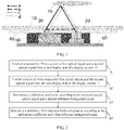
FIG. 1 is a schematic structural diagram of an electronic device according to an embodiment of the present invention; and -
FIG. 2 is a schematic flowchart of a background noise calibration method according to an embodiment of the present invention. - Reference signs:
-
Display screen 10;Transmitter 20;Receiver 30; -
Middle frame 40; Light-shielding material piece 50; Printedcircuit motherboard 60;Object 70. - To make the objectives, technical solutions, and advantages of embodiments of the present invention clearer, the following clearly and completely describes the technical solutions of the embodiments of the present invention with reference to accompanying drawings of the present invention. Apparently, the described embodiments are a part rather than all of the embodiments of the present invention. All other embodiments obtained by a person of ordinary skill in the art based on the described embodiments of the present invention shall fall within the protection scope of the present invention.
- An electronic device according to an embodiment of the present invention will be described in detail below.
- As shown in
FIG. 1 , an electronic device according to an embodiment of the present invention includes adisplay screen 10, and further includes atransmitter 20, areceiver 30, and a processor. - Specifically, the
transmitter 20 is disposed on a non-display side of thedisplay screen 10, and thetransmitter 20 is configured to transmit a first optical signal and a second optical signal to thedisplay screen 10, and transmittance of the first optical signal passing through thedisplay screen 10 is greater than that of the second optical signal passing through thedisplay screen 10. Thereceiver 30 is disposed on the non-display side of thedisplay screen 10, and thereceiver 30 is configured to receive the first optical signal and the second optical signal. The processor is connected to thereceiver 30, and the processor is configured to determine a calibration coefficient according to the second optical signal received by thereceiver 30 and a second reference background noise, and determine a calibrated first reference background noise according to the calibration coefficient and a first reference background noise. The first reference background noise is a theoretical value of the first optical signal received by thereceiver 30 when no object approaches thedisplay screen 10, and the second reference background noise is a theoretical value of the second optical signal received by thereceiver 30 when no object approaches thedisplay screen 10. - That is, the electronic device mainly includes the
display screen 10, thetransmitter 20, thereceiver 30, and the processor. Both thetransmitter 20 and thereceiver 30 are disposed on the non-display side of thedisplay screen 10. Thetransmitter 20 transmits the first optical signal and the second optical signal to thedisplay screen 10. Thetransmitter 20 may be a light-emitting diode (Light Emitting Diode, LED) light source. Thereceiver 30 receives the first optical signal and the second optical signal. The first optical signal may be infrared light, such as infrared light with a wavelength of 950 nm. The transmittance of the first optical signal passing through thedisplay screen 10 is greater than that of the second optical signal passing through thedisplay screen 10, and the transmittance of the second optical signal passing through thedisplay screen 10 may be much less than that of the first optical signal passing through thedisplay screen 10. Therefore, relatively few second optical signals pass through thedisplay screen 10, and more first optical signals pass through thedisplay screen 10. When an object approaches thedisplay screen 10, relatively many first optical signals are reflected by the object, which helps thereceiver 30 to receive the signals and accurate calculation. A wavelength of light with low transmittance passing through thedisplay 10 needs to be selected for the second optical signal, and the wavelength can be adjusted for transmittance for different display screens. According to transmittance for most current display screens, ultraviolet light with a wavelength less than 400 nm can be used for the second optical signal. Transmittance of the ultraviolet light with the wavelength less than 400 nm passing through the existing display screen is not more than 1% generally, which is low. - As shown in
FIG. 1 , light paths a and b are paths of the first optical signal, and optical paths c and d are paths of the second optical signal. When no object approaches thedisplay screen 10, only light paths b and d exist. When an object 70 (such as a person's face) is approaching, light paths a and c exist after a reflection by theobject 70. During application, light path c is not expected, and existence of light path c may cause the received second optical signal to be changed when the object is approaching, and then it is determined by mistake that a structural change occurs. Because light path c needs to pass through thedisplay screen 10 twice, transmittance of the second optical signal passing through thedisplay screen 10 is very low. For example, the transmittance is 1%, when energy of the second optical signal transmitted by thetransmitter 20 and passing through the display screen is P, energy received by thereceiver 30 is only 1/10,000 of P. Therefore, the energy is extremely low and can be ignored. - When no object approaches the
display screen 10, thereceiver 30 will not receive an optical signal reflected by the object. When no structural deformation occurs, the first reference background noise is a theoretical value of the first optical signal received by thereceiver 30 when no object approaches thedisplay screen 10, and the second reference background noise is a theoretical value of the second optical signal received by thereceiver 30 when no object approaches thedisplay screen 10. A second optical signal received by thereceiver 30 when the structural deformation occurs is different from the second optical signal received when the no structural deformation occurs, and the first reference background noise and the second reference background noise are also changed when the structural deformation occurs. Because the transmittance of the second optical signal passing through the display screen is relatively low, a variation of the second reference background noise can be detected more accurately compared with a variation of the first reference background noise. To more accurately calculate a change in the first reference background noise caused by the structural deformation, it is necessary to calibrate the first reference background noise after obtaining a calibration coefficient according to the second optical signal received by thereceiver 30. - The processor is connected to the
receiver 30, and the processor can determine the calibration coefficient according to the second optical signal received by thereceiver 30 and the second reference background noise. Because relatively few second optical signals pass through thedisplay screen 10, when the structural deformation occurs, the calibration coefficient can be determined according to the second optical signal received by thereceiver 30 and the second reference background noise. The first reference background noise is also changed correspondingly due to the structural deformation, and the calibrated first reference background noise can be determined according to the calibration coefficient and the first reference background noise. That is, when no object is approaching, only light paths b and d exist, and the first reference background noise and the second reference background noise can be obtained first. When the second reference background noise is changed, it is considered that structural deformation occurs, resulting in a change in the light paths. A change rate is calculated according to the change in the second reference background noise. Because paths of the first optical signal and the second optical signal are completely consistent, the change rate can be used as a calibration coefficient for calibrating the second reference background noise. - In an actual process, light path c does exist, light path c can be measured, and a maximum change value of light path c can be calculated. The maximum change value of light path c can be used as a minimum sensitivity range. During measurement, the maximum change value of c can be obtained while something is used to approach the display screen slowly, for example, the maximum change value of c is cmax. The structural deformation is considered to occur only when the change value of the second reference background noise is greater than the cmax. No structural deformation is considered to occur when the change value of the second reference background noise is less than the cmax. In addition, the display screen may be unglued during use by a user, which may affect other functions except infrared light, resulting in function abnormity. Micro-deformation of the structure can be detected through the change in the second reference background noise, so that parameter compensation can be performed or the user can be prompted. In addition, when the structural deformation (such as screen unglued) occurs, the user may not go through after-sales processing. Therefore, a defect rate of an unglued screen cannot be collected. Data of the structural deformation can further be collected based on the change in the second reference background noise, which helps to improve subsequent design, product quality, and user experience.
- In the electronic device of the present invention, the calibration coefficient can be determined through the second optical signal and the second reference background noise, and the calibrated first reference background noise can be determined according to the calibration coefficient and the first reference background noise, and then the change in the first reference background noise caused by the structural deformation can be calibrated. Therefore, the influence of the structural deformation on the first reference background noise can be reduced, and the calibrated first reference background noise has high accuracy, which helps to accurately determine whether an object approaches the display screen.
- In some embodiments of the present invention, the processor is further configured to use a ratio of the second optical signal received by the
receiver 30 to the second reference background noise as the calibration coefficient. The processor is further configured to use a product of the calibration coefficient and the first reference background noise as the calibrated first reference background noise. For example, the first reference background noise is A when no object approaches thedisplay screen 10, and the second reference background noise is B when no object approaches thedisplay screen 10, and a second optical signal actually received by thereceiver 30 is αB when the structural deformation occurs. In this case, a ratio of the second optical signal received by thereceiver 30 to the second reference background noise is α, and α is used as the calibration coefficient. The first reference background noise is calibrated through α when the structural deformation occurs, and a product of the calibration coefficient α and a first reference background noise A is used as the calibrated first reference background noise αA. That is, the first reference background noise is αA when the structural deformation occurs, and a change in the first reference background noise caused by the structural deformation is calibrated, so that the influence of the structural deformation on the first reference background noise can be reduced. - In some other embodiments of the present invention, the processor is further configured to calculate, according to the first optical signal received by the
receiver 30 and the calibrated first reference background noise, a variation of the first optical signal received by thereceiver 30, and determine, according to the variation, whether an object approaches thedisplay screen 10. The variation of the first optical signal received by thereceiver 30 can be calculated more accurately through the calibrated first reference background noise, and it can be accurately determined whether an object approaches thedisplay screen 10. - Optionally, the electronic device may further include a
middle frame 40. Thedisplay screen 10 is disposed on themiddle frame 40. An elastic layer, such as elastic glue, may be disposed between themiddle frame 40 and thedisplay screen 10, and hard contact between thedisplay screen 10 and themiddle frame 40 can be avoided through the elastic layer. The electronic device further includes a printedcircuit motherboard 60. The printedcircuit motherboard 60 is disposed on the non-display side of thedisplay screen 10. Thetransmitter 20 and thereceiver 30 are respectively disposed between thedisplay screen 10 and the printedcircuit motherboard 60, and thetransmitter 20 and thereceiver 30 can be disposed on the printedcircuit motherboard 60. A light-shieldingmaterial piece 50 is disposed on outer peripheries of thetransmitter 20 and thereceiver 30. Under the condition that thetransmitter 20 transmitting an optical signal and thereceiver 30 receiving the optical signal are not affected, a light-shielding material can be filled in gaps between components to reduce mutual crosstalk of optical signals. The light-shieldingmaterial piece 50 may be disposed in gaps between thetransmitter 20, thereceiver 30, and themiddle frame 40. For example, the light-shieldingmaterial piece 50 is provided in a gap between thetransmitter 20 and thereceiver 30, a gap between thetransmitter 20 and themiddle frame 40, and a gap between thereceiver 30 and themiddle frame 40, respectively. The light-shieldingmaterial piece 50 may be a silicone material cover, which can reduce the mutual crosstalk of optical signals, so that thereceiver 30 can accurately calculate a received optical signal and reduce a deviation. - An embodiment of the present invention further provides a background noise calibration method.
- As shown in
FIG. 2 , the background noise calibration method according to the embodiment of the present invention can be applied to the electronic device described in the foregoing embodiment and includes: - Step S1: Control a
transmitter 20 to transmit a first optical signal and a second optical signal from a non-display side of adisplay screen 10; - Step S2: Control a
receiver 30 to receive the first optical signal and the second optical signal from the non-display side of thedisplay screen 10; - Step S3: Determine a calibration coefficient according to the received second optical signal and a second reference background noise; and
- Step S4: Determine a calibrated first reference background noise according to the calibration coefficient and a first reference background noise.
- Transmittance of the first optical signal passing through the
display screen 10 is greater than that of the second optical signal passing through thedisplay screen 10. The first reference background noise is a theoretical value of the first optical signal received by thereceiver 30 when no object approaches thedisplay screen 10, and the second reference background noise is a theoretical value of the second optical signal received by thereceiver 30 when no object approaches thedisplay screen 10. It should be noted that S1 to S4 in the foregoing steps do not represent a necessary sequence of steps, and a sequence of different steps can be adjusted according to actual needs. - That is, in the foregoing background noise calibration method, the first optical signal and the second optical signal are transmitted from the non-display side of the
display screen 10, and the first optical signal and the second optical signal are received from the non-display side of thedisplay screen 10. The first optical signal and the second optical signal can be transmitted through thetransmitter 20, and the first optical signal and the second optical signal can be received through thereceiver 30. The transmittance of the first optical signal passing through thedisplay screen 10 is greater than that of the second optical signal passing through thedisplay screen 10, and the transmittance of the second optical signal passing through thedisplay screen 10 may be much less than that of the first optical signal passing through thedisplay screen 10. Therefore, relatively few second optical signals pass through thedisplay screen 10, and more first optical signals pass through thedisplay screen 10. When an object approaches thedisplay screen 10, relatively many first optical signals are reflected by the object, which help receiving by thereceiver 30. - The calibration coefficient can be determined according to the second optical signal received by the
receiver 30 and the second reference background noise. Because relatively few second optical signals pass through thedisplay screen 10, when structural deformation occurs, the calibration coefficient can be determined according to the second optical signal received by thereceiver 30 and the second reference background noise. The first reference background noise is a theoretical value of the first optical signal received by thereceiver 30 when no object approaches thedisplay screen 10, and the second reference background noise is a theoretical value of the second optical signal received by thereceiver 30 when no object approaches thedisplay screen 10. The first reference background noise of the first optical signal is also changed correspondingly due to the structural deformation, and the calibrated first reference background noise can be determined according to the calibration coefficient and the first reference background noise. In the foregoing method, a change in the first reference background noise caused by the structural deformation can be calibrated. Therefore, the influence of the structural deformation on the first reference background noise can be reduced, and the calibrated first reference background noise has high accuracy, which helps to determine whether an object approaches the display screen. - In this embodiment of the present invention, the determining a calibration coefficient according to the received second optical signal and a second reference background noise includes: using a ratio of the second optical signal received by the
receiver 30 to the second reference background noise as the calibration coefficient. - According to this embodiment of the present invention, the determining a calibrated first reference background noise according to the calibration coefficient and a first reference background noise includes: using a product of the calibration coefficient and the first reference background noise as the calibrated first reference background noise.
- In this embodiment of the present invention, the method may further include: calculating a variation of the received first optical signal according to the received first optical signal and the calibrated first reference background noise, and determining whether an object approaches the
display screen 10 according to the variation. The variation of the first optical signal can be accurately determined according to the calibrated first reference background noise, which helps to accurately determine whether an object approaches the display screen. - An embodiment of the present invention further provides an electronic device, including a processor, a memory, and a computer program that is stored in the memory and that can be run on the processor. When the computer program is executed by the processor, processes of the foregoing method embodiments are implemented, and a same technical effect can be achieved. To avoid repetition, details are not described herein again.
- Unless otherwise defined, the technical terms or scientific terms used in the present invention shall have the general meanings understood by a person having ordinary skill in the field in which the present invention falls. The "first", "second" and similar words used in the present invention are only intended to distinguish different components, rather than to indicate any order, quantity, or importance. Similar words such as "connect" or "connection" are not limited to physical or mechanical connections, but may include electrical connections, no matter it is direct or indirect. "Upper", "lower", "left", "right", and the like are only intended to indicate a relative positional relationship. When an absolute position of the described object changes, the relative positional relationship changes accordingly as well.
- A person of ordinary skill in the art may realize that units and algorithm steps of various examples described with reference to the embodiments disclosed in this specification can be implemented by using electronic hardware, or a combination of computer software and the electronic hardware. Whether these functions are performed by using hardware or software depends on a specific application and design constraints of the technical solutions. A person of ordinary skill in the art may use different methods to achieve the described functions for each particular application, but it should not be considered that the implementation goes beyond the scope of the present disclosure.
- A person of ordinary skill in the art may clearly understand that, for convenient and simple description, for the specific working processes of the system, apparatus, and unit described above, reference may be made to a corresponding process in the foregoing method embodiments, and details are not described herein again.
- In the embodiments provided in this application, it should be understood that the disclosed apparatus and method may be implemented in other manners. For example, the apparatus embodiment described above is only an example. For example, division into the units is only logical function division. There may be other division manners in actual implementation, for example, a plurality of units or components may be combined or integrated into another system, or some features may be ignored or not implemented. In addition, the displayed or discussed mutual couplings or direct couplings or communication connections may be implemented by using some interfaces. The indirect couplings or communication connections between apparatuses or units may be implemented in electronic, mechanical, or other forms.
- The units described as separate parts may or may not be physically separate, and parts displayed as units may or may not be physical units, that is, may be located in one location, or may be distributed on a plurality of network units. Some or all of the units may be selected according to actual needs to achieve the objective of the solutions of the embodiments.
- In addition, function units in the embodiments of the present disclosure may be integrated into one processing unit, or each of the units may exist alone physically, or two or more units are integrated into one unit.
- If the functions are implemented in a form of software function units and sold or used as independent products, the functions may be stored in a computer-readable storage medium. Based on such understanding, the technical solutions of the present disclosure essentially, or the part contributing to the related art may be implemented in a form of a software product. The computer software product is stored in a storage medium, and includes several instructions for enabling a computer device (which may be a personal computer, a server, a network device, or the like) to perform all or some of the steps of the methods described in the embodiments of the present disclosure. The foregoing storage medium includes various media that can store a program code such as a USB flash disk, a mobile hard disk, a ROM, a RAM, a magnetic disk, an optical disc, or the like.
- A person of ordinary skill in the art can understand that all or some of the procedures in the methods of the foregoing embodiments may be implemented by a computer program controlling related hardware. The program may be stored in a computer-readable storage medium. When the program is executed, the procedures of the embodiments of the foregoing methods may be performed. The storage medium includes a magnetic disk, a compact disc, a read-only memory (Read-Only Memory, ROM), a random access memory (Random Access Memory, RAM), or the like.
- It can be understood that the embodiments described in the present disclosure may be implemented by hardware, software, firmware, middleware, microcode, or a combination thereof. For implementation with hardware, modules, units, and subunits may be implemented in one or more application specific integrated circuits (Application Specific Integrated Circuits, ASIC), a digital signal processor (Digital Signal Processor, DSP), a digital signal processing device (DSP Device, DSPD), a programmable logic device (Programmable Logic Device, PLD), a field-programmable gate array (Field-Programmable Gate Array, FPGA), a general-purpose processor, a controller, a microcontroller, a microprocessor, another electronic unit for implementing the functions of the present disclosure, or a combination thereof.
- For implementation with software, technologies described in the embodiments of the present disclosure may be implemented by executing functional modules (for example, a process and a function) in the embodiments of the present disclosure. A software code may be stored in the memory and executed by the processor. The memory may be implemented in the processor or outside the processor.
- The foregoing embodiments are preferred embodiments of the present invention. It should be noted that those of ordinary skill in the art can make various improvements and modifications without departing from the principles described in the present invention, which shall fall within the protective scope of the present invention.
Claims (12)
- An electronic device, comprising a display screen, and further comprising:a transmitter, disposed on a non-display side of the display screen, and configured to transmit a first optical signal and a second optical signal to the display screen, wherein transmittance of the first optical signal passing through the display screen is greater than that of the second optical signal passing through the display screen;a receiver, disposed on the non-display side of the display screen, and configured to receive the first optical signal and the second optical signal; anda processor, connected to the receiver, and configured to determine a calibration coefficient according to the second optical signal received by the receiver and a second reference background noise, and determine a calibrated first reference background noise according to the calibration coefficient and a first reference background noise, wherein the first reference background noise is a theoretical value of the first optical signal received by the receiver when no object approaches the display screen, and the second reference background noise is a theoretical value of the second optical signal received by the receiver when no object approaches the display screen.
- The electronic device according to claim 1, wherein the processor is further configured to use a ratio of the second optical signal received by the receiver to the second reference background noise as the calibration coefficient.
- The electronic device according to claim 1, wherein the processor is further configured to use a product of the calibration coefficient and the first reference background noise as the calibrated first reference background noise.
- The electronic device according to claim 1, wherein the processor is further configured to calculate, according to the first optical signal received by the receiver and the calibrated first reference background noise, a variation of the first optical signal received by the receiver, and determine, according to the variation, whether an object approaches the display screen.
- The electronic device according to claim 1, further comprising:a middle frame, wherein the display screen is disposed on the middle frame; anda printed circuit motherboard, disposed on the non-display side of the display screen, wherein the transmitter and the receiver are respectively disposed between the display screen and the printed circuit motherboard, and a light-shielding material piece is disposed on outer peripheries of the transmitter and the receiver.
- A background noise calibration method, applied to the electronic device according to any one of claims 1 to 5, and comprising:controlling a transmitter to transmit a first optical signal and a second optical signal from a non-display side of a display screen;controlling a receiver to receive the first optical signal and the second optical signal from the non-display side of the display screen; determining a calibration coefficient according to the received second optical signal and a second reference background noise; anddetermining a calibrated first reference background noise according to the calibration coefficient and a first reference background noise,wherein transmittance of the first optical signal passing through the display screen is greater than that of the second optical signal passing through the display screen; andthe first reference background noise is a theoretical value of the first optical signal received by the receiver when no object approaches the display screen, and the second reference background noise is a theoretical value of the second optical signal received by the receiver when no object approaches the display screen.
- The method according to claim 6, wherein the determining a calibration coefficient according to the received second optical signal and a second reference background noise comprises:
using a ratio of the second optical signal received by the receiver to the second reference background noise as the calibration coefficient. - The method according to claim 6, wherein the determining a calibrated first reference background noise according to the calibration coefficient and a first reference background noise comprises:
using a product of the calibration coefficient and the first reference background noise as the calibrated first reference background noise. - The method according to claim 6, further comprising:
calculating a variation of the received first optical signal according to the received first optical signal and the calibrated first reference background noise, and determining, according to the variation, whether an object approaches the display screen. - An electronic device, comprising a processor, a memory, and a computer program that is stored in the memory and that can be run on the processor, wherein when the computer program is executed by the processor, the steps of the method according to any one of claims 6 to 9 are implemented.
- A computer software product, stored in a non-volatile storage medium, wherein the computer software product is configured to be executed by at least one processor to implement the steps of the method according to any one of claims 6 to 9.
- An electronic device, configured to implement the method according to any one of claims 6 to 9.
Applications Claiming Priority (2)
| Application Number | Priority Date | Filing Date | Title |
|---|---|---|---|
| CN202010071361.0A CN111289956B (en) | 2020-01-21 | 2020-01-21 | Electronic equipment and noise floor calibration method |
| PCT/CN2021/071724 WO2021147766A1 (en) | 2020-01-21 | 2021-01-14 | Electronic device and noise floor calibration method |
Publications (3)
| Publication Number | Publication Date |
|---|---|
| EP4095549A1 true EP4095549A1 (en) | 2022-11-30 |
| EP4095549A4 EP4095549A4 (en) | 2023-06-28 |
| EP4095549B1 EP4095549B1 (en) | 2025-10-29 |
Family
ID=71025628
Family Applications (1)
| Application Number | Title | Priority Date | Filing Date |
|---|---|---|---|
| EP21745045.1A Active EP4095549B1 (en) | 2020-01-21 | 2021-01-14 | Electronic device and noise floor calibration method |
Country Status (7)
| Country | Link |
|---|---|
| US (1) | US20220350003A1 (en) |
| EP (1) | EP4095549B1 (en) |
| JP (1) | JP7353505B2 (en) |
| KR (1) | KR102842398B1 (en) |
| CN (1) | CN111289956B (en) |
| ES (1) | ES3053583T3 (en) |
| WO (1) | WO2021147766A1 (en) |
Families Citing this family (4)
| Publication number | Priority date | Publication date | Assignee | Title |
|---|---|---|---|---|
| CN111289956B (en) * | 2020-01-21 | 2022-04-29 | 维沃移动通信有限公司 | Electronic equipment and noise floor calibration method |
| CN113411448B (en) * | 2021-06-16 | 2022-06-24 | 维沃移动通信有限公司 | Infrared signal processing method and device, electronic equipment and readable storage medium |
| CN114499710B (en) * | 2022-04-02 | 2022-06-21 | 成都爱瑞无线科技有限公司 | Background noise change measuring method, background noise change measuring device, background noise change measuring system, electronic device, and storage medium |
| CN115560681A (en) * | 2022-09-21 | 2023-01-03 | 北京小米移动软件有限公司 | Distance detection method and device, electronic equipment and storage medium |
Family Cites Families (18)
| Publication number | Priority date | Publication date | Assignee | Title |
|---|---|---|---|---|
| US5103085A (en) * | 1990-09-05 | 1992-04-07 | Zimmerman Thomas G | Photoelectric proximity detector and switch |
| CH697495B1 (en) | 2005-04-01 | 2008-11-14 | Baumer Electric Ag | Optical sensor and method for suppressing stray light errors. |
| US20100245289A1 (en) * | 2009-03-31 | 2010-09-30 | Miroslav Svajda | Apparatus and method for optical proximity sensing and touch input control |
| CN102540170B (en) * | 2012-02-10 | 2016-02-10 | 江苏徕兹光电科技股份有限公司 | Based on calibration steps and the distance measuring equipment thereof of the phase measurement of dual-wavelength laser pipe |
| CN103245938B (en) * | 2012-02-14 | 2017-11-14 | 英特赛尔美国有限公司 | The optical proximity sensor of one or more objects is detected using ECT echo cancellation technique |
| US11199454B2 (en) * | 2015-03-12 | 2021-12-14 | Maxim Integrated Products, Inc. | Heat imaging thermophile device and method |
| CN106019260A (en) * | 2016-04-29 | 2016-10-12 | 乐视控股(北京)有限公司 | Distance sensor anti-fouling method and system on mobile terminal |
| EP3290950A1 (en) * | 2016-09-01 | 2018-03-07 | ams AG | Optical sensor module and method for manufacturing an optical sensor module for time-of-flight measurement |
| CN106791209A (en) * | 2017-03-10 | 2017-05-31 | 上海传英信息技术有限公司 | The self-checking device and method of distance of mobile terminal sensor |
| CN107219515A (en) * | 2017-05-25 | 2017-09-29 | 深圳市金立通信设备有限公司 | The parameter calibrating method and terminal of a kind of range sensor |
| CN109428961A (en) * | 2017-08-29 | 2019-03-05 | 中兴通讯股份有限公司 | A kind of processing method and mobile terminal close to light sensation |
| CN107943345B (en) * | 2017-11-22 | 2020-10-02 | Oppo广东移动通信有限公司 | Calibration method, device, storage medium and electronic device for proximity sensor |
| US20190162820A1 (en) * | 2017-11-29 | 2019-05-30 | Delphi Technologies, Llc | Automated vehicle sensor calibration system |
| CN108172175A (en) * | 2018-01-04 | 2018-06-15 | 广东小天才科技有限公司 | Correction method, device and equipment for optical sensor and storage medium |
| CN109167857B (en) * | 2018-09-30 | 2022-06-07 | Oppo广东移动通信有限公司 | Calibration method, electronic device, storage medium, and computer apparatus |
| CN109840032B (en) * | 2019-01-24 | 2022-04-12 | Oppo广东移动通信有限公司 | Method and device for calibrating proximity sensor, electronic equipment and storage medium |
| CN110609977B (en) * | 2019-08-06 | 2023-08-11 | 深圳市万普拉斯科技有限公司 | Noise floor adjustment processing method, device and computer equipment based on proximity sensor |
| CN111289956B (en) * | 2020-01-21 | 2022-04-29 | 维沃移动通信有限公司 | Electronic equipment and noise floor calibration method |
-
2020
- 2020-01-21 CN CN202010071361.0A patent/CN111289956B/en active Active
-
2021
- 2021-01-14 KR KR1020227028772A patent/KR102842398B1/en active Active
- 2021-01-14 WO PCT/CN2021/071724 patent/WO2021147766A1/en not_active Ceased
- 2021-01-14 ES ES21745045T patent/ES3053583T3/en active Active
- 2021-01-14 EP EP21745045.1A patent/EP4095549B1/en active Active
- 2021-01-14 JP JP2022542331A patent/JP7353505B2/en active Active
-
2022
- 2022-07-18 US US17/866,817 patent/US20220350003A1/en active Pending
Also Published As
| Publication number | Publication date |
|---|---|
| US20220350003A1 (en) | 2022-11-03 |
| JP7353505B2 (en) | 2023-09-29 |
| EP4095549B1 (en) | 2025-10-29 |
| KR102842398B1 (en) | 2025-08-06 |
| KR20220127921A (en) | 2022-09-20 |
| JP2023510348A (en) | 2023-03-13 |
| EP4095549A4 (en) | 2023-06-28 |
| ES3053583T3 (en) | 2026-01-23 |
| CN111289956A (en) | 2020-06-16 |
| WO2021147766A1 (en) | 2021-07-29 |
| CN111289956B (en) | 2022-04-29 |
Similar Documents
| Publication | Publication Date | Title |
|---|---|---|
| US20220350003A1 (en) | Electronic device and background noise calibration method | |
| CN104503574B (en) | A kind of calibration method of range sensor, apparatus and system | |
| US20110181892A1 (en) | Automatic calibration technique for time of flight (tof) transceivers | |
| CN105866781B (en) | Data processing method and electronic equipment | |
| CN109738004B (en) | Method and device for calibrating proximity sensor, electronic equipment and storage medium | |
| CN114190975A (en) | Ultrasound probe with indicator remote control capability | |
| CN112204420A (en) | Time-of-flight rangefinder for structured light systems | |
| CN104840210B (en) | Image display device and its control method | |
| CN111854966A (en) | Temperature measurement method, device, wearable device and medium | |
| KR20170011521A (en) | Smart Thermometer and Method for Calculating Temperature Thereof | |
| CN118225153B (en) | Photoelectric sensor calibration detection method, device, photoelectric sensor and storage medium | |
| TW202034846A (en) | Sensor device | |
| CN110597044A (en) | Optical detection device and related rotary watch | |
| CN106302912A (en) | The characteristic method of mobile terminal alignment light sensation and mobile terminal | |
| TWI498789B (en) | Proximity sensing method, proximity sensing device, and electronic device | |
| US20140160075A1 (en) | Optical touch system, method of touch detection, method of calibration, and computer program product | |
| CN114420046A (en) | Brightness detection method, brightness detection device, and storage medium | |
| CN108354614A (en) | Blood glucose detection method, blood glucose detection correction method, and blood glucose detection device | |
| US10394388B2 (en) | Adaptive reflected light touch sensor | |
| CN113411448B (en) | Infrared signal processing method and device, electronic equipment and readable storage medium | |
| US20210306244A1 (en) | Signal latency detection system | |
| CN108700404B (en) | Photoelectric device | |
| TWI892467B (en) | Colorimeter and control method thereof | |
| CN112346596B (en) | Ultrasonic touch device and touch calibration method | |
| TWI885814B (en) | Ultrasonic scanning apparatus |
Legal Events
| Date | Code | Title | Description |
|---|---|---|---|
| STAA | Information on the status of an ep patent application or granted ep patent |
Free format text: STATUS: THE INTERNATIONAL PUBLICATION HAS BEEN MADE |
|
| PUAI | Public reference made under article 153(3) epc to a published international application that has entered the european phase |
Free format text: ORIGINAL CODE: 0009012 |
|
| STAA | Information on the status of an ep patent application or granted ep patent |
Free format text: STATUS: REQUEST FOR EXAMINATION WAS MADE |
|
| 17P | Request for examination filed |
Effective date: 20220809 |
|
| AK | Designated contracting states |
Kind code of ref document: A1 Designated state(s): AL AT BE BG CH CY CZ DE DK EE ES FI FR GB GR HR HU IE IS IT LI LT LU LV MC MK MT NL NO PL PT RO RS SE SI SK SM TR |
|
| DAV | Request for validation of the european patent (deleted) | ||
| DAX | Request for extension of the european patent (deleted) | ||
| A4 | Supplementary search report drawn up and despatched |
Effective date: 20230526 |
|
| RIC1 | Information provided on ipc code assigned before grant |
Ipc: G01S 17/08 20060101ALI20230522BHEP Ipc: H04M 1/725 20210101ALI20230522BHEP Ipc: G01S 7/497 20060101AFI20230522BHEP |
|
| STAA | Information on the status of an ep patent application or granted ep patent |
Free format text: STATUS: EXAMINATION IS IN PROGRESS |
|
| 17Q | First examination report despatched |
Effective date: 20240923 |
|
| GRAP | Despatch of communication of intention to grant a patent |
Free format text: ORIGINAL CODE: EPIDOSNIGR1 |
|
| STAA | Information on the status of an ep patent application or granted ep patent |
Free format text: STATUS: GRANT OF PATENT IS INTENDED |
|
| INTG | Intention to grant announced |
Effective date: 20250819 |
|
| GRAS | Grant fee paid |
Free format text: ORIGINAL CODE: EPIDOSNIGR3 |
|
| GRAA | (expected) grant |
Free format text: ORIGINAL CODE: 0009210 |
|
| STAA | Information on the status of an ep patent application or granted ep patent |
Free format text: STATUS: THE PATENT HAS BEEN GRANTED |
|
| AK | Designated contracting states |
Kind code of ref document: B1 Designated state(s): AL AT BE BG CH CY CZ DE DK EE ES FI FR GB GR HR HU IE IS IT LI LT LU LV MC MK MT NL NO PL PT RO RS SE SI SK SM TR |
|
| REG | Reference to a national code |
Ref country code: CH Ref legal event code: F10 Free format text: ST27 STATUS EVENT CODE: U-0-0-F10-F00 (AS PROVIDED BY THE NATIONAL OFFICE) Effective date: 20251029 Ref country code: GB Ref legal event code: FG4D |
|
| REG | Reference to a national code |
Ref country code: IE Ref legal event code: FG4D |
|
| REG | Reference to a national code |
Ref country code: DE Ref legal event code: R096 Ref document number: 602021041289 Country of ref document: DE |
|
| REG | Reference to a national code |
Ref country code: NL Ref legal event code: FP |
|
| PGFP | Annual fee paid to national office [announced via postgrant information from national office to epo] |
Ref country code: GB Payment date: 20251127 Year of fee payment: 6 |
|
| PGFP | Annual fee paid to national office [announced via postgrant information from national office to epo] |
Ref country code: NL Payment date: 20251215 Year of fee payment: 6 Ref country code: FR Payment date: 20251128 Year of fee payment: 6 |
|
| REG | Reference to a national code |
Ref country code: ES Ref legal event code: FG2A Ref document number: 3053583 Country of ref document: ES Kind code of ref document: T3 Effective date: 20260123 |
|
| PGFP | Annual fee paid to national office [announced via postgrant information from national office to epo] |
Ref country code: ES Payment date: 20260209 Year of fee payment: 6 |
|
| REG | Reference to a national code |
Ref country code: LT Ref legal event code: MG9D |
|
| PG25 | Lapsed in a contracting state [announced via postgrant information from national office to epo] |
Ref country code: NO Free format text: LAPSE BECAUSE OF FAILURE TO SUBMIT A TRANSLATION OF THE DESCRIPTION OR TO PAY THE FEE WITHIN THE PRESCRIBED TIME-LIMIT Effective date: 20260129 |
|
| PGFP | Annual fee paid to national office [announced via postgrant information from national office to epo] |
Ref country code: DE Payment date: 20251203 Year of fee payment: 6 |
|
| PG25 | Lapsed in a contracting state [announced via postgrant information from national office to epo] |
Ref country code: HR Free format text: LAPSE BECAUSE OF FAILURE TO SUBMIT A TRANSLATION OF THE DESCRIPTION OR TO PAY THE FEE WITHIN THE PRESCRIBED TIME-LIMIT Effective date: 20251029 Ref country code: FI Free format text: LAPSE BECAUSE OF FAILURE TO SUBMIT A TRANSLATION OF THE DESCRIPTION OR TO PAY THE FEE WITHIN THE PRESCRIBED TIME-LIMIT Effective date: 20251029 Ref country code: AT Free format text: LAPSE BECAUSE OF FAILURE TO SUBMIT A TRANSLATION OF THE DESCRIPTION OR TO PAY THE FEE WITHIN THE PRESCRIBED TIME-LIMIT Effective date: 20251029 |
|
| REG | Reference to a national code |
Ref country code: AT Ref legal event code: MK05 Ref document number: 1852145 Country of ref document: AT Kind code of ref document: T Effective date: 20251029 |
|
| PG25 | Lapsed in a contracting state [announced via postgrant information from national office to epo] |
Ref country code: RS Free format text: LAPSE BECAUSE OF FAILURE TO SUBMIT A TRANSLATION OF THE DESCRIPTION OR TO PAY THE FEE WITHIN THE PRESCRIBED TIME-LIMIT Effective date: 20260129 |
|
| PG25 | Lapsed in a contracting state [announced via postgrant information from national office to epo] |
Ref country code: IS Free format text: LAPSE BECAUSE OF FAILURE TO SUBMIT A TRANSLATION OF THE DESCRIPTION OR TO PAY THE FEE WITHIN THE PRESCRIBED TIME-LIMIT Effective date: 20260228 |
|
| PG25 | Lapsed in a contracting state [announced via postgrant information from national office to epo] |
Ref country code: PT Free format text: LAPSE BECAUSE OF FAILURE TO SUBMIT A TRANSLATION OF THE DESCRIPTION OR TO PAY THE FEE WITHIN THE PRESCRIBED TIME-LIMIT Effective date: 20260302 |
|
| PG25 | Lapsed in a contracting state [announced via postgrant information from national office to epo] |
Ref country code: PL Free format text: LAPSE BECAUSE OF FAILURE TO SUBMIT A TRANSLATION OF THE DESCRIPTION OR TO PAY THE FEE WITHIN THE PRESCRIBED TIME-LIMIT Effective date: 20251029 |
|
| PG25 | Lapsed in a contracting state [announced via postgrant information from national office to epo] |
Ref country code: LV Free format text: LAPSE BECAUSE OF FAILURE TO SUBMIT A TRANSLATION OF THE DESCRIPTION OR TO PAY THE FEE WITHIN THE PRESCRIBED TIME-LIMIT Effective date: 20251029 |
|
| PG25 | Lapsed in a contracting state [announced via postgrant information from national office to epo] |
Ref country code: BG Free format text: LAPSE BECAUSE OF FAILURE TO SUBMIT A TRANSLATION OF THE DESCRIPTION OR TO PAY THE FEE WITHIN THE PRESCRIBED TIME-LIMIT Effective date: 20251029 |