EP4095544A1 - Sensor assembly for vehicle and vehicle - Google Patents
Sensor assembly for vehicle and vehicle Download PDFInfo
- Publication number
- EP4095544A1 EP4095544A1 EP22165408.0A EP22165408A EP4095544A1 EP 4095544 A1 EP4095544 A1 EP 4095544A1 EP 22165408 A EP22165408 A EP 22165408A EP 4095544 A1 EP4095544 A1 EP 4095544A1
- Authority
- EP
- European Patent Office
- Prior art keywords
- rotary shaft
- sensor body
- positioning bracket
- sensor
- sidewall
- Prior art date
- Legal status (The legal status is an assumption and is not a legal conclusion. Google has not performed a legal analysis and makes no representation as to the accuracy of the status listed.)
- Granted
Links
Images

Classifications
-
- G—PHYSICS
- G01—MEASURING; TESTING
- G01S—RADIO DIRECTION-FINDING; RADIO NAVIGATION; DETERMINING DISTANCE OR VELOCITY BY USE OF RADIO WAVES; LOCATING OR PRESENCE-DETECTING BY USE OF THE REFLECTION OR RERADIATION OF RADIO WAVES; ANALOGOUS ARRANGEMENTS USING OTHER WAVES
- G01S13/00—Systems using the reflection or reradiation of radio waves, e.g. radar systems; Analogous systems using reflection or reradiation of waves whose nature or wavelength is irrelevant or unspecified
- G01S13/88—Radar or analogous systems specially adapted for specific applications
- G01S13/93—Radar or analogous systems specially adapted for specific applications for anti-collision purposes
- G01S13/931—Radar or analogous systems specially adapted for specific applications for anti-collision purposes of land vehicles
-
- G—PHYSICS
- G01—MEASURING; TESTING
- G01S—RADIO DIRECTION-FINDING; RADIO NAVIGATION; DETERMINING DISTANCE OR VELOCITY BY USE OF RADIO WAVES; LOCATING OR PRESENCE-DETECTING BY USE OF THE REFLECTION OR RERADIATION OF RADIO WAVES; ANALOGOUS ARRANGEMENTS USING OTHER WAVES
- G01S7/00—Details of systems according to groups G01S13/00, G01S15/00, G01S17/00
- G01S7/02—Details of systems according to groups G01S13/00, G01S15/00, G01S17/00 of systems according to group G01S13/00
- G01S7/027—Constructional details of housings, e.g. form, type, material or ruggedness
-
- B—PERFORMING OPERATIONS; TRANSPORTING
- B60—VEHICLES IN GENERAL
- B60R—VEHICLES, VEHICLE FITTINGS, OR VEHICLE PARTS, NOT OTHERWISE PROVIDED FOR
- B60R11/00—Arrangements for holding or mounting articles, not otherwise provided for
- B60R11/04—Mounting of cameras operative during drive; Arrangement of controls thereof relative to the vehicle
-
- B—PERFORMING OPERATIONS; TRANSPORTING
- B60—VEHICLES IN GENERAL
- B60R—VEHICLES, VEHICLE FITTINGS, OR VEHICLE PARTS, NOT OTHERWISE PROVIDED FOR
- B60R11/00—Arrangements for holding or mounting articles, not otherwise provided for
- B60R2011/0001—Arrangements for holding or mounting articles, not otherwise provided for characterised by position
- B60R2011/004—Arrangements for holding or mounting articles, not otherwise provided for characterised by position outside the vehicle
-
- B—PERFORMING OPERATIONS; TRANSPORTING
- B60—VEHICLES IN GENERAL
- B60R—VEHICLES, VEHICLE FITTINGS, OR VEHICLE PARTS, NOT OTHERWISE PROVIDED FOR
- B60R11/00—Arrangements for holding or mounting articles, not otherwise provided for
- B60R2011/0042—Arrangements for holding or mounting articles, not otherwise provided for characterised by mounting means
- B60R2011/008—Adjustable or movable supports
- B60R2011/0085—Adjustable or movable supports with adjustment by rotation in their operational position
-
- G—PHYSICS
- G01—MEASURING; TESTING
- G01S—RADIO DIRECTION-FINDING; RADIO NAVIGATION; DETERMINING DISTANCE OR VELOCITY BY USE OF RADIO WAVES; LOCATING OR PRESENCE-DETECTING BY USE OF THE REFLECTION OR RERADIATION OF RADIO WAVES; ANALOGOUS ARRANGEMENTS USING OTHER WAVES
- G01S13/00—Systems using the reflection or reradiation of radio waves, e.g. radar systems; Analogous systems using reflection or reradiation of waves whose nature or wavelength is irrelevant or unspecified
- G01S13/88—Radar or analogous systems specially adapted for specific applications
- G01S13/93—Radar or analogous systems specially adapted for specific applications for anti-collision purposes
- G01S13/931—Radar or analogous systems specially adapted for specific applications for anti-collision purposes of land vehicles
- G01S2013/9327—Sensor installation details
-
- H—ELECTRICITY
- H04—ELECTRIC COMMUNICATION TECHNIQUE
- H04N—PICTORIAL COMMUNICATION, e.g. TELEVISION
- H04N23/00—Cameras or camera modules comprising electronic image sensors; Control thereof
- H04N23/50—Constructional details
- H04N23/51—Housings
Definitions
- the disclosure relates to the technical field of vehicles, and more particularly to a sensor assembly for a vehicle and a vehicle comprising the sensor assembly.
- sensors for automatic driving such as a vehicle-mounted camera and a radar need to calibrate a target before use, which requires that the installation accuracy of sensors is within a certain tolerance range, otherwise, the calibration will fail.
- the angular accuracy of the camera and the radar exceeding a target range is one of the most likely causes of calibration failure.
- embodiments of the disclosure provide a sensor assembly for a vehicle and a vehicle comprising the sensor assembly, in order to effectively solve or alleviate at least one of currently existing disadvantages, or to meet at least one of current requirements.
- the embodiments of the disclosure relate to a sensor assembly for a vehicle, comprising:
- the positioning bracket comprises opposing first and second sidewalls
- the sensor body is installed between the first sidewall and the second sidewall such that the first side and the second side of the sensor body are respectively adjacent to the first sidewall and the second sidewall.
- the first rotary shaft receiving portion and the second rotary shaft receiving portion are respectively provided on the first sidewall and the second sidewall.
- the first rotary shaft receiving portion and the second rotary shaft receiving portion are respectively rotary shaft sleeves extending relative to each other from the first sidewall and the second sidewall.
- the positioning bracket further comprises a connecting wall connecting the first sidewall to the second sidewall, the third side of the sensor body is adjacent to the connecting wall, and the detent structure is provided on the connecting wall.
- the connecting wall is formed as a top portion of the positioning bracket, and the toothed structure is provided on a side edge of the top portion of the sensor body.
- the senor comprises a camera, a radar, or a combination thereof.
- the toothed structure comprises a rack.
- the detent structure comprises a reed that can be snapped into any one of notches in the toothed structure.
- the embodiments of the disclosure relate to a vehicle comprising the sensor assembly described above.
- orientation terms such as “top”, “bottom”, “front” and “back” referred to herein are defined with respect to the orientations in the drawings, and they are relative concepts and can thus vary depending on their different practical locations. Therefore, these or other orientation terms should not be construed as limiting terms.
- the embodiments of the disclosure relate to a sensor assembly for a vehicle, in which the angle of a sensor relative to its positioning bracket is adjustable, so that after the sensor is assembled at a target position by means of the positioning bracket, the angle of the sensor can also be adjusted with respect to the positioning bracket to obtain the angular accuracy required for calibrating the sensor.
- the sensor may comprise a camera, a radar, or a combination thereof.
- a sensor assembly 1 comprises a sensor body 11 and a positioning bracket 13 for positioning the sensor body 11.
- a first rotary shaft 21 and a second rotary shaft (not visible in the figures) are respectively provided on opposing first side 111 and second side 112 of the sensor body 11, and the positioning bracket 13 is correspondingly provided with a first rotary shaft receiving portion 23 and a second rotary shaft receiving portion 24.
- the first rotary shaft 21 and the second rotary shaft are respectively rotatably accommodated in the first rotary shaft receiving portion 23 and the second rotary shaft receiving portion 24 to achieve rotation of the sensor body 11 relative to the positioning bracket 13.
- a toothed structure 22 is provided on a third side 115 of the sensor body 11, and a detent structure 25 is correspondingly provided on the positioning bracket 13.
- the third side 115 refers to a side other than the first side 111 and the second side 112, and may be, for example, a top side, an inclined upper side between the top side and the outer side.
- the positioning bracket 13 may comprise opposing first sidewall (such as a left sidewall) 131 and second sidewall (such as a right sidewall) 132, which may roughly parallelly extend.
- the sensor body 11 is installed between the first sidewall 131 and the second sidewall 132 such that the first side 111 and the second side 112 of the sensor body 11 are respectively adjacent to the first sidewall 131 and the second sidewall 132.
- the first rotary shaft receiving portion 23 and the second rotary shaft receiving portion 24 may be respectively provided on the first sidewall 131 and the second sidewall 132.
- the first rotary shaft receiving portion 23 and the second rotary shaft receiving portion 24 are rotary shaft sleeves respectively extending relative to each other from the inner sides of the first sidewall 131 and the second sidewall 132, the cross sections of the rotary shaft sleeves are semicircular with openings facing upward.
- the rotary shaft sleeves may be in the shape of a complete circular ring, or may be in any other suitable shape.
- the positioning bracket 13 further comprises a connecting wall 133 connecting the first sidewall 131 to the second sidewall 132, the third side 115 of the sensor body 11 is adjacent to the connecting wall 133, and the detent structure 25 is provided on the connecting wall 133.
- the connecting wall 133 is formed as a top portion of the positioning bracket 13, and the first sidewall 131 and the second sidewall 132 may vertically downwardly extend from the connecting wall 133.
- the connecting wall 133 extends non-horizontally, but is not perpendicular to the first sidewall 131 and the second sidewall 132.
- the toothed structure 22 is provided on a side edge of the top portion of the sensor body 11 (such as a joining edge 118 of a top surface 116 and an outer side surface 117).
- the first rotary shaft 21 and the second rotary shaft respectively extend towards two sides from the positions of the first side 111 and the second side 112 of the sensor body 11 close to a rear side surface 119.
- the toothed structure 22 comprises a rack 221, and a connecting portion 222 connecting the rack 221 to the sensor body 11.
- the connecting portion 222 obliquely extends upward and outward in the vicinity of an intermediate point of he joining edge of the top surface and the outer side surface of the sensor body 11, and the extending direction is perpendicular to the joining edge 118 but not perpendicular to the top surface 116 and the outer side surface 117.
- the rack 221 extends in a direction roughly perpendicular to the connecting portion 222.
- the detent structure 25 comprises a reed 251 that can be snapped into any notch (equivalent to an opening between adjacent teeth) in the toothed structure 22, and a connecting portion 252 connecting the reed 251 to the positioning bracket 13.
- the connecting portion 252 extends downward and outward from the position on the lower surface of the connecting wall 133 of the positioning bracket 13 corresponding to the toothed structure 22, for example, perpendicular to the lower surface of the connecting wall 133.
- the reed 251 extends in a direction roughly perpendicular to the connecting portion 252.
- the contact position of the toothed structure 22 and the detent structure 25, the mating position of the first shaft 21 and the first rotary shaft receiving portion 23, and the mating position of the second shaft and the second rotary shaft receiving portion 24 may be substantially connected to form a triangular shape.
- first rotary shaft 21, the second rotary shaft, and the toothed structure 22 are integrally formed with the sensor body 11, and the first rotary shaft receiving portion 23, the second rotary shaft receiving portion 24, and the detent structure 25 are integrally formed with the positioning bracket 13.
- a stable three-point fixing structure may be formed by means the contact point of the toothed structure 22 and the detent structure 25 and the point of rotation between the sensor body 11 and the positioning bracket 13 thereof.
- the embodiments of the disclosure relate to a vehicle comprising the sensor assembly described above.
- a vehicle comprising the sensor assembly described above.
Landscapes
- Engineering & Computer Science (AREA)
- Radar, Positioning & Navigation (AREA)
- Remote Sensing (AREA)
- Physics & Mathematics (AREA)
- General Physics & Mathematics (AREA)
- Computer Networks & Wireless Communication (AREA)
- Electromagnetism (AREA)
- Mechanical Engineering (AREA)
- Radar Systems Or Details Thereof (AREA)
Abstract
Description
- The disclosure relates to the technical field of vehicles, and more particularly to a sensor assembly for a vehicle and a vehicle comprising the sensor assembly.
- At present, sensors for automatic driving such as a vehicle-mounted camera and a radar need to calibrate a target before use, which requires that the installation accuracy of sensors is within a certain tolerance range, otherwise, the calibration will fail. The angular accuracy of the camera and the radar exceeding a target range is one of the most likely causes of calibration failure.
- Therefore, there is a need in the art for a novel sensor assembly in order to achieve the angular accuracy required for calibration of the camera and the radar.
- In view of the above, embodiments of the disclosure provide a sensor assembly for a vehicle and a vehicle comprising the sensor assembly, in order to effectively solve or alleviate at least one of currently existing disadvantages, or to meet at least one of current requirements.
- According to an aspect, the embodiments of the disclosure relate to a sensor assembly for a vehicle, comprising:
- a sensor body; and
- a positioning bracket for positioning the sensor body, wherein
- a first rotary shaft and a second rotary shaft are respectively provided on opposing first and second sides of the sensor body, and the first rotary shaft and the second rotary shaft are respectively rotatably accommodated in a first rotary shaft receiving portion and a second rotary shaft receiving portion provided on the positioning bracket so as to achieve the rotation of the sensor body relative to the positioning bracket; and
- a toothed structure is provided on a third side of the sensor body, other than the first side and the second side, and a detent structure is correspondingly provided on the positioning bracket, and when the sensor body rotates to a desired angle relative to the positioning bracket, fixing of the sensor body relative to the positioning bracket is enabled by means of the engagement between the toothed structure and the detent structure.
- Optionally, in the sensor assembly, the positioning bracket comprises opposing first and second sidewalls, the sensor body is installed between the first sidewall and the second sidewall such that the first side and the second side of the sensor body are respectively adjacent to the first sidewall and the second sidewall.
- Optionally, in the sensor assembly, the first rotary shaft receiving portion and the second rotary shaft receiving portion are respectively provided on the first sidewall and the second sidewall.
- Optionally, in the sensor assembly, the first rotary shaft receiving portion and the second rotary shaft receiving portion are respectively rotary shaft sleeves extending relative to each other from the first sidewall and the second sidewall.
- Optionally, in the sensor assembly, the positioning bracket further comprises a connecting wall connecting the first sidewall to the second sidewall, the third side of the sensor body is adjacent to the connecting wall, and the detent structure is provided on the connecting wall.
- Optionally, in the sensor assembly, the connecting wall is formed as a top portion of the positioning bracket, and the toothed structure is provided on a side edge of the top portion of the sensor body.
- Optionally, in the sensor assembly, the sensor comprises a camera, a radar, or a combination thereof.
- Optionally, in the sensor assembly, the toothed structure comprises a rack.
- Optionally, in the sensor assembly, the detent structure comprises a reed that can be snapped into any one of notches in the toothed structure.
- On another aspect, the embodiments of the disclosure relate to a vehicle comprising the sensor assembly described above.
- The disclosure will be further described below in detail in conjunction with the accompanying drawings and the preferred embodiments. However, those skilled in the art would have appreciated that these drawings are drawn merely for the purpose of illustrating the preferred embodiments, and thus should not be taken as limitation on the scope of the disclosure. In addition, unless otherwise specified, the drawings are merely intended to be conceptually illustrative of the constitution or construction of described objects and may include exaggerated representations, and the drawings are not necessarily drawn to scale. Furthermore, in different drawings, the same reference numerals denote the same or substantially the same components.
-
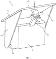
Fig. 1 is a perspective schematic diagram of an exemplary sensor assembly according to an embodiment of the disclosure. -
Fig. 2 is an exploded schematic diagram of the sensor assembly shown inFig. 1 . - Some embodiments of the disclosure will now be described in more detail in conjunction with the accompanying drawings. Unless expressly defined otherwise herein, scientific and technical terms used herein have the meanings that are commonly understood by those of skill in the art.
- The orientation terms such as "top", "bottom", "front" and "back" referred to herein are defined with respect to the orientations in the drawings, and they are relative concepts and can thus vary depending on their different practical locations. Therefore, these or other orientation terms should not be construed as limiting terms.
- The terms "comprising" and "having", and similar words used herein means that items other than those listed thereafter and equivalents thereof are also within the scope of the disclosure. The terms "or" and "either" are not meant to be exclusive, but rather refer to the presence of at least one of referenced items, and include the case where a combination of the referenced items may be present. The term "and/or" includes any and all combinations of one or more of the referenced items. The terms such as "some embodiments" mentioned herein means that a particular element (for example, a feature, a structure, and/or a characteristic) described relevant with the disclosure is included in at least one embodiment described in this specification, and may or may not be present in other embodiments. In addition, it should be understood that described inventive elements may be combined in any suitable manner.
- According to an aspect, the embodiments of the disclosure relate to a sensor assembly for a vehicle, in which the angle of a sensor relative to its positioning bracket is adjustable, so that after the sensor is assembled at a target position by means of the positioning bracket, the angle of the sensor can also be adjusted with respect to the positioning bracket to obtain the angular accuracy required for calibrating the sensor. The sensor may comprise a camera, a radar, or a combination thereof.
- As shown in
Figs. 1 and2 , asensor assembly 1 comprises asensor body 11 and apositioning bracket 13 for positioning thesensor body 11. A firstrotary shaft 21 and a second rotary shaft (not visible in the figures) are respectively provided on opposingfirst side 111 andsecond side 112 of thesensor body 11, and thepositioning bracket 13 is correspondingly provided with a first rotaryshaft receiving portion 23 and a second rotaryshaft receiving portion 24. The firstrotary shaft 21 and the second rotary shaft are respectively rotatably accommodated in the first rotaryshaft receiving portion 23 and the second rotaryshaft receiving portion 24 to achieve rotation of thesensor body 11 relative to thepositioning bracket 13. Atoothed structure 22 is provided on athird side 115 of thesensor body 11, and adetent structure 25 is correspondingly provided on thepositioning bracket 13. When thesensor body 11 rotates to a desired angle relative to thepositioning bracket 13, fixating of thesensor body 11 relative to thepositioning bracket 13 is achieved by means of the engagement between thetoothed structure 22 and thedetent structure 25. Thethird side 115 refers to a side other than thefirst side 111 and thesecond side 112, and may be, for example, a top side, an inclined upper side between the top side and the outer side. - The
positioning bracket 13 may comprise opposing first sidewall (such as a left sidewall) 131 and second sidewall (such as a right sidewall) 132, which may roughly parallelly extend. Thesensor body 11 is installed between thefirst sidewall 131 and thesecond sidewall 132 such that thefirst side 111 and thesecond side 112 of thesensor body 11 are respectively adjacent to thefirst sidewall 131 and thesecond sidewall 132. - The first rotary
shaft receiving portion 23 and the second rotaryshaft receiving portion 24 may be respectively provided on thefirst sidewall 131 and thesecond sidewall 132. For example, in the illustrated embodiment, the first rotaryshaft receiving portion 23 and the second rotaryshaft receiving portion 24 are rotary shaft sleeves respectively extending relative to each other from the inner sides of thefirst sidewall 131 and thesecond sidewall 132, the cross sections of the rotary shaft sleeves are semicircular with openings facing upward. In other embodiments, the rotary shaft sleeves may be in the shape of a complete circular ring, or may be in any other suitable shape. - In some embodiments, the
positioning bracket 13 further comprises a connectingwall 133 connecting thefirst sidewall 131 to thesecond sidewall 132, thethird side 115 of thesensor body 11 is adjacent to the connectingwall 133, and thedetent structure 25 is provided on theconnecting wall 133. In some embodiments, theconnecting wall 133 is formed as a top portion of thepositioning bracket 13, and thefirst sidewall 131 and thesecond sidewall 132 may vertically downwardly extend from theconnecting wall 133. In some embodiments, theconnecting wall 133 extends non-horizontally, but is not perpendicular to thefirst sidewall 131 and thesecond sidewall 132. In some embodiments, thetoothed structure 22 is provided on a side edge of the top portion of the sensor body 11 (such as a joiningedge 118 of atop surface 116 and an outer side surface 117). The firstrotary shaft 21 and the second rotary shaft respectively extend towards two sides from the positions of thefirst side 111 and thesecond side 112 of thesensor body 11 close to arear side surface 119. - In some embodiments, the
toothed structure 22 comprises arack 221, and a connectingportion 222 connecting therack 221 to thesensor body 11. In some embodiments, the connectingportion 222 obliquely extends upward and outward in the vicinity of an intermediate point of he joining edge of the top surface and the outer side surface of thesensor body 11, and the extending direction is perpendicular to the joiningedge 118 but not perpendicular to thetop surface 116 and theouter side surface 117. Therack 221 extends in a direction roughly perpendicular to the connectingportion 222. - In some embodiments, the
detent structure 25 comprises areed 251 that can be snapped into any notch (equivalent to an opening between adjacent teeth) in thetoothed structure 22, and a connectingportion 252 connecting thereed 251 to thepositioning bracket 13. In some embodiments, the connectingportion 252 extends downward and outward from the position on the lower surface of the connectingwall 133 of thepositioning bracket 13 corresponding to thetoothed structure 22, for example, perpendicular to the lower surface of theconnecting wall 133. Thereed 251 extends in a direction roughly perpendicular to the connectingportion 252. - In some embodiments, the contact position of the
toothed structure 22 and thedetent structure 25, the mating position of thefirst shaft 21 and the first rotaryshaft receiving portion 23, and the mating position of the second shaft and the second rotaryshaft receiving portion 24 may be substantially connected to form a triangular shape. - In the illustrated embodiment, the first
rotary shaft 21, the second rotary shaft, and thetoothed structure 22 are integrally formed with thesensor body 11, and the first rotaryshaft receiving portion 23, the second rotaryshaft receiving portion 24, and thedetent structure 25 are integrally formed with thepositioning bracket 13. - In the
sensor assembly 1 of the foregoing embodiment, by providing thesensor body 11 with an angle adjustment tooth and providing thepositioning bracket 13 with the detent structure engaged with the angle adjustment tooth, the angle adjustment and positioning of the sensor may be simply and conveniently achieved without an additional adjustment tool. In addition, a stable three-point fixing structure may be formed by means the contact point of thetoothed structure 22 and thedetent structure 25 and the point of rotation between thesensor body 11 and thepositioning bracket 13 thereof. - According to another aspect, the embodiments of the disclosure relate to a vehicle comprising the sensor assembly described above. In light of the above disclosure, those skilled in the art readily obtain a vehicle comprising the sensor assembly described above.
- The foregoing specific embodiments are illustrated to provide a thorough and comprehensive understanding of the disclosed content of the disclosure, but the disclosure is not limited to these specific embodiments. It will be apparent to those skilled in the art that various modifications, equivalents, and variations may also be performed on the disclosure without departing from the spirit of the disclosure, which should be within the scope of the disclosure.
Claims (10)
- A sensor assembly for a vehicle, comprising:a sensor body; anda positioning bracket for positioning the sensor body, whereina first rotary shaft and a second rotary shaft are respectively provided on opposing first and second sides of the sensor body, and the first rotary shaft and the second rotary shaft are respectively rotatably accommodated in a first rotary shaft receiving portion and a second rotary shaft receiving portion provided on the positioning bracket so as to achieve the rotation of the sensor body relative to the positioning bracket; anda toothed structure is provided on a third side of the sensor body, other than the first side and the second side, and a detent structure is correspondingly provided on the positioning bracket, and when the sensor body rotates to a desired angle relative to the positioning bracket, fixing of the sensor body relative to the positioning bracket is enabled by means of the engagement between the toothed structure and the detent structure.
- The sensor assembly according to claim 1, wherein the positioning bracket comprises opposing first and second sidewalls, the sensor body is installed between the first sidewall and the second sidewall such that the first side and the second side of the sensor body are respectively adjacent to the first sidewall and the second sidewall.
- The sensor assembly according to claim 2, wherein the first rotary shaft receiving portion and the second rotary shaft receiving portion are respectively provided on the first sidewall and the second sidewall.
- The sensor assembly according to claim 2 or 3, wherein the first rotary shaft receiving portion and the second rotary shaft receiving portion are respectively rotary shaft sleeves extending relative to each other from the first sidewall and the second sidewall.
- The sensor assembly according to claim 2, 3, or 4, wherein the positioning bracket further comprises a connecting wall connecting the first sidewall to the second sidewall, the third side of the sensor body is adjacent to the connecting wall, and the detent structure is provided on the connecting wall.
- The sensor assembly according to claim 5, wherein the connecting wall is formed as a top portion of the positioning bracket, and the toothed structure is provided on a side edge of the top portion of the sensor body.
- The sensor assembly according to any one of claims 1 to 6, wherein the sensor comprises a camera, a radar, or a combination thereof.
- The sensor assembly according to any one of claims 1 to 6, wherein the toothed structure comprises a rack.
- The sensor assembly according to any one of claims 1 to 6, wherein the detent structure comprises a reed that can be snapped into any one of notches in the toothed structure.
- A vehicle, comprising a sensor assembly for the vehicle, preferably the sensor assembly according to any one of claims 1 to 9, the sensor assembly comprising:a sensor body; anda positioning bracket for positioning the sensor body, whereina first rotary shaft and a second rotary shaft are respectively provided on opposing first and second sides of the sensor body, and the first rotary shaft and the second rotary shaft are respectively rotatably accommodated in a first rotary shaft receiving portion and a second rotary shaft receiving portion provided on the positioning bracket so as to achieve the rotation of the sensor body relative to the positioning bracket; anda toothed structure is provided on a third side of the sensor body, other than the first side and the second side, and a detent structure is correspondingly provided on the positioning bracket, and when the sensor body rotates to a desired angle relative to the positioning bracket, fixing of the sensor body relative to the positioning bracket is enabled by means of the engagement between the toothed structure and the detent structure.
Applications Claiming Priority (1)
| Application Number | Priority Date | Filing Date | Title |
|---|---|---|---|
| CN202121130324.9U CN216309020U (en) | 2021-05-25 | 2021-05-25 | Sensor assembly for vehicle and vehicle |
Publications (2)
| Publication Number | Publication Date |
|---|---|
| EP4095544A1 true EP4095544A1 (en) | 2022-11-30 |
| EP4095544B1 EP4095544B1 (en) | 2024-12-11 |
Family
ID=81081748
Family Applications (1)
| Application Number | Title | Priority Date | Filing Date |
|---|---|---|---|
| EP22165408.0A Active EP4095544B1 (en) | 2021-05-25 | 2022-03-30 | Sensor assembly for vehicle and vehicle |
Country Status (3)
| Country | Link |
|---|---|
| US (1) | US12130358B2 (en) |
| EP (1) | EP4095544B1 (en) |
| CN (1) | CN216309020U (en) |
Citations (2)
| Publication number | Priority date | Publication date | Assignee | Title |
|---|---|---|---|---|
| GB2129987A (en) * | 1982-11-11 | 1984-05-23 | Haldex Ab | Preventing falsification of odometer readings |
| US9491338B1 (en) * | 2015-10-19 | 2016-11-08 | Motorola Solutions, Inc. | Sealed articulating camera for a communication device |
-
2021
- 2021-05-25 CN CN202121130324.9U patent/CN216309020U/en active Active
-
2022
- 2022-03-30 EP EP22165408.0A patent/EP4095544B1/en active Active
- 2022-05-20 US US17/749,297 patent/US12130358B2/en active Active
Patent Citations (2)
| Publication number | Priority date | Publication date | Assignee | Title |
|---|---|---|---|---|
| GB2129987A (en) * | 1982-11-11 | 1984-05-23 | Haldex Ab | Preventing falsification of odometer readings |
| US9491338B1 (en) * | 2015-10-19 | 2016-11-08 | Motorola Solutions, Inc. | Sealed articulating camera for a communication device |
Also Published As
| Publication number | Publication date |
|---|---|
| CN216309020U (en) | 2022-04-15 |
| EP4095544B1 (en) | 2024-12-11 |
| US20220379822A1 (en) | 2022-12-01 |
| US12130358B2 (en) | 2024-10-29 |
Similar Documents
| Publication | Publication Date | Title |
|---|---|---|
| CA2533064C (en) | Rotary variable resistor | |
| CA2029502C (en) | Headlight for motor vehicle | |
| US6842152B2 (en) | Method for adjusting detection axis of object detection system | |
| US4760499A (en) | Adjustable automobile headlight assembly | |
| CN104204841B (en) | Sensor holder for a sensor for object detection | |
| KR20010102430A (en) | Rearview mirror assembly with internally mounted compass sensor | |
| US7534021B2 (en) | Bumper assembly with fog lamp bezel | |
| WO2015064420A1 (en) | Radiator grille | |
| US20050161581A1 (en) | Photodetector | |
| EP4095544A1 (en) | Sensor assembly for vehicle and vehicle | |
| JP2019123418A (en) | External sensor unit of vehicle | |
| US20220305993A1 (en) | 2k door gasket, rear view device, vehicle and assembling and attachment method | |
| US20030090820A1 (en) | Inner mirror with built-in antenna | |
| US20010004853A1 (en) | Accelerator with attachment of pedal arm | |
| BR102019007008A2 (en) | DEVICE WITH POINTER FOR AN INDICATOR INSTRUMENT, PARTICULARLY FOR A VEHICLE | |
| US7513663B2 (en) | Adaptive lighting system having dynamic recalibration | |
| JP2021004024A (en) | Vehicle distance sensor mounting structure | |
| JP6609830B2 (en) | Vehicle external sensor unit | |
| JP4105291B2 (en) | Steering mechanism and assembly method thereof | |
| US12472880B2 (en) | Adjustable support for attaching electronic and/or mechanical components to a windshield of a vehicle | |
| CN211642042U (en) | Mounting brackets | |
| JPH0644727Y2 (en) | Air outlet device for vehicle | |
| JP3891385B2 (en) | Cup holder structure | |
| EP2554435B1 (en) | Vehicle side-view mirror | |
| JP2001006493A (en) | Mounting structure of cable reel and winker.lighting switch on steering shaft |
Legal Events
| Date | Code | Title | Description |
|---|---|---|---|
| PUAI | Public reference made under article 153(3) epc to a published international application that has entered the european phase |
Free format text: ORIGINAL CODE: 0009012 |
|
| STAA | Information on the status of an ep patent application or granted ep patent |
Free format text: STATUS: REQUEST FOR EXAMINATION WAS MADE |
|
| 17P | Request for examination filed |
Effective date: 20220331 |
|
| AK | Designated contracting states |
Kind code of ref document: A1 Designated state(s): AL AT BE BG CH CY CZ DE DK EE ES FI FR GB GR HR HU IE IS IT LI LT LU LV MC MK MT NL NO PL PT RO RS SE SI SK SM TR |
|
| GRAP | Despatch of communication of intention to grant a patent |
Free format text: ORIGINAL CODE: EPIDOSNIGR1 |
|
| STAA | Information on the status of an ep patent application or granted ep patent |
Free format text: STATUS: GRANT OF PATENT IS INTENDED |
|
| RIC1 | Information provided on ipc code assigned before grant |
Ipc: B60R 11/04 20060101ALI20240718BHEP Ipc: B60R 11/00 20060101ALI20240718BHEP Ipc: G01S 7/02 20060101AFI20240718BHEP |
|
| INTG | Intention to grant announced |
Effective date: 20240805 |
|
| GRAS | Grant fee paid |
Free format text: ORIGINAL CODE: EPIDOSNIGR3 |
|
| GRAA | (expected) grant |
Free format text: ORIGINAL CODE: 0009210 |
|
| STAA | Information on the status of an ep patent application or granted ep patent |
Free format text: STATUS: THE PATENT HAS BEEN GRANTED |
|
| AK | Designated contracting states |
Kind code of ref document: B1 Designated state(s): AL AT BE BG CH CY CZ DE DK EE ES FI FR GB GR HR HU IE IS IT LI LT LU LV MC MK MT NL NO PL PT RO RS SE SI SK SM TR |
|
| REG | Reference to a national code |
Ref country code: GB Ref legal event code: FG4D |
|
| REG | Reference to a national code |
Ref country code: CH Ref legal event code: EP |
|
| REG | Reference to a national code |
Ref country code: DE Ref legal event code: R096 Ref document number: 602022008527 Country of ref document: DE |
|
| REG | Reference to a national code |
Ref country code: IE Ref legal event code: FG4D |
|
| REG | Reference to a national code |
Ref country code: LT Ref legal event code: MG9D |
|
| PG25 | Lapsed in a contracting state [announced via postgrant information from national office to epo] |
Ref country code: HR Free format text: LAPSE BECAUSE OF FAILURE TO SUBMIT A TRANSLATION OF THE DESCRIPTION OR TO PAY THE FEE WITHIN THE PRESCRIBED TIME-LIMIT Effective date: 20241211 |
|
| PG25 | Lapsed in a contracting state [announced via postgrant information from national office to epo] |
Ref country code: FI Free format text: LAPSE BECAUSE OF FAILURE TO SUBMIT A TRANSLATION OF THE DESCRIPTION OR TO PAY THE FEE WITHIN THE PRESCRIBED TIME-LIMIT Effective date: 20241211 |
|
| PG25 | Lapsed in a contracting state [announced via postgrant information from national office to epo] |
Ref country code: BG Free format text: LAPSE BECAUSE OF FAILURE TO SUBMIT A TRANSLATION OF THE DESCRIPTION OR TO PAY THE FEE WITHIN THE PRESCRIBED TIME-LIMIT Effective date: 20241211 |
|
| REG | Reference to a national code |
Ref country code: NL Ref legal event code: MP Effective date: 20241211 |
|
| PG25 | Lapsed in a contracting state [announced via postgrant information from national office to epo] |
Ref country code: ES Free format text: LAPSE BECAUSE OF FAILURE TO SUBMIT A TRANSLATION OF THE DESCRIPTION OR TO PAY THE FEE WITHIN THE PRESCRIBED TIME-LIMIT Effective date: 20241211 |
|
| PG25 | Lapsed in a contracting state [announced via postgrant information from national office to epo] |
Ref country code: NO Free format text: LAPSE BECAUSE OF FAILURE TO SUBMIT A TRANSLATION OF THE DESCRIPTION OR TO PAY THE FEE WITHIN THE PRESCRIBED TIME-LIMIT Effective date: 20250311 |
|
| PG25 | Lapsed in a contracting state [announced via postgrant information from national office to epo] |
Ref country code: LV Free format text: LAPSE BECAUSE OF FAILURE TO SUBMIT A TRANSLATION OF THE DESCRIPTION OR TO PAY THE FEE WITHIN THE PRESCRIBED TIME-LIMIT Effective date: 20241211 Ref country code: GR Free format text: LAPSE BECAUSE OF FAILURE TO SUBMIT A TRANSLATION OF THE DESCRIPTION OR TO PAY THE FEE WITHIN THE PRESCRIBED TIME-LIMIT Effective date: 20250312 |
|
| PG25 | Lapsed in a contracting state [announced via postgrant information from national office to epo] |
Ref country code: RS Free format text: LAPSE BECAUSE OF FAILURE TO SUBMIT A TRANSLATION OF THE DESCRIPTION OR TO PAY THE FEE WITHIN THE PRESCRIBED TIME-LIMIT Effective date: 20250311 |
|
| PG25 | Lapsed in a contracting state [announced via postgrant information from national office to epo] |
Ref country code: NL Free format text: LAPSE BECAUSE OF FAILURE TO SUBMIT A TRANSLATION OF THE DESCRIPTION OR TO PAY THE FEE WITHIN THE PRESCRIBED TIME-LIMIT Effective date: 20241211 |
|
| REG | Reference to a national code |
Ref country code: AT Ref legal event code: MK05 Ref document number: 1750803 Country of ref document: AT Kind code of ref document: T Effective date: 20241211 |
|
| PG25 | Lapsed in a contracting state [announced via postgrant information from national office to epo] |
Ref country code: SM Free format text: LAPSE BECAUSE OF FAILURE TO SUBMIT A TRANSLATION OF THE DESCRIPTION OR TO PAY THE FEE WITHIN THE PRESCRIBED TIME-LIMIT Effective date: 20241211 |
|
| PG25 | Lapsed in a contracting state [announced via postgrant information from national office to epo] |
Ref country code: PL Free format text: LAPSE BECAUSE OF FAILURE TO SUBMIT A TRANSLATION OF THE DESCRIPTION OR TO PAY THE FEE WITHIN THE PRESCRIBED TIME-LIMIT Effective date: 20241211 |
|
| PG25 | Lapsed in a contracting state [announced via postgrant information from national office to epo] |
Ref country code: IS Free format text: LAPSE BECAUSE OF FAILURE TO SUBMIT A TRANSLATION OF THE DESCRIPTION OR TO PAY THE FEE WITHIN THE PRESCRIBED TIME-LIMIT Effective date: 20250411 |
|
| PG25 | Lapsed in a contracting state [announced via postgrant information from national office to epo] |
Ref country code: PT Free format text: LAPSE BECAUSE OF FAILURE TO SUBMIT A TRANSLATION OF THE DESCRIPTION OR TO PAY THE FEE WITHIN THE PRESCRIBED TIME-LIMIT Effective date: 20250411 |
|
| PG25 | Lapsed in a contracting state [announced via postgrant information from national office to epo] |
Ref country code: EE Free format text: LAPSE BECAUSE OF FAILURE TO SUBMIT A TRANSLATION OF THE DESCRIPTION OR TO PAY THE FEE WITHIN THE PRESCRIBED TIME-LIMIT Effective date: 20241211 |
|
| PG25 | Lapsed in a contracting state [announced via postgrant information from national office to epo] |
Ref country code: RO Free format text: LAPSE BECAUSE OF FAILURE TO SUBMIT A TRANSLATION OF THE DESCRIPTION OR TO PAY THE FEE WITHIN THE PRESCRIBED TIME-LIMIT Effective date: 20241211 Ref country code: AT Free format text: LAPSE BECAUSE OF FAILURE TO SUBMIT A TRANSLATION OF THE DESCRIPTION OR TO PAY THE FEE WITHIN THE PRESCRIBED TIME-LIMIT Effective date: 20241211 |
|
| PG25 | Lapsed in a contracting state [announced via postgrant information from national office to epo] |
Ref country code: SK Free format text: LAPSE BECAUSE OF FAILURE TO SUBMIT A TRANSLATION OF THE DESCRIPTION OR TO PAY THE FEE WITHIN THE PRESCRIBED TIME-LIMIT Effective date: 20241211 |
|
| PG25 | Lapsed in a contracting state [announced via postgrant information from national office to epo] |
Ref country code: CZ Free format text: LAPSE BECAUSE OF FAILURE TO SUBMIT A TRANSLATION OF THE DESCRIPTION OR TO PAY THE FEE WITHIN THE PRESCRIBED TIME-LIMIT Effective date: 20241211 |
|
| PG25 | Lapsed in a contracting state [announced via postgrant information from national office to epo] |
Ref country code: IT Free format text: LAPSE BECAUSE OF FAILURE TO SUBMIT A TRANSLATION OF THE DESCRIPTION OR TO PAY THE FEE WITHIN THE PRESCRIBED TIME-LIMIT Effective date: 20241211 |
|
| PG25 | Lapsed in a contracting state [announced via postgrant information from national office to epo] |
Ref country code: SE Free format text: LAPSE BECAUSE OF FAILURE TO SUBMIT A TRANSLATION OF THE DESCRIPTION OR TO PAY THE FEE WITHIN THE PRESCRIBED TIME-LIMIT Effective date: 20241211 |
|
| REG | Reference to a national code |
Ref country code: DE Ref legal event code: R097 Ref document number: 602022008527 Country of ref document: DE |
|
| PG25 | Lapsed in a contracting state [announced via postgrant information from national office to epo] |
Ref country code: DK Free format text: LAPSE BECAUSE OF FAILURE TO SUBMIT A TRANSLATION OF THE DESCRIPTION OR TO PAY THE FEE WITHIN THE PRESCRIBED TIME-LIMIT Effective date: 20241211 |
|
| PG25 | Lapsed in a contracting state [announced via postgrant information from national office to epo] |
Ref country code: MC Free format text: LAPSE BECAUSE OF FAILURE TO SUBMIT A TRANSLATION OF THE DESCRIPTION OR TO PAY THE FEE WITHIN THE PRESCRIBED TIME-LIMIT Effective date: 20241211 |
|
| PLBE | No opposition filed within time limit |
Free format text: ORIGINAL CODE: 0009261 |
|
| STAA | Information on the status of an ep patent application or granted ep patent |
Free format text: STATUS: NO OPPOSITION FILED WITHIN TIME LIMIT |
|
| REG | Reference to a national code |
Ref country code: CH Ref legal event code: L10 Free format text: ST27 STATUS EVENT CODE: U-0-0-L10-L00 (AS PROVIDED BY THE NATIONAL OFFICE) Effective date: 20251022 |
|
| REG | Reference to a national code |
Ref country code: CH Ref legal event code: H13 Free format text: ST27 STATUS EVENT CODE: U-0-0-H10-H13 (AS PROVIDED BY THE NATIONAL OFFICE) Effective date: 20251023 |
|
| PG25 | Lapsed in a contracting state [announced via postgrant information from national office to epo] |
Ref country code: LU Free format text: LAPSE BECAUSE OF NON-PAYMENT OF DUE FEES Effective date: 20250330 |
|
| 26N | No opposition filed |
Effective date: 20250912 |
|
| REG | Reference to a national code |
Ref country code: BE Ref legal event code: MM Effective date: 20250331 |
|
| PG25 | Lapsed in a contracting state [announced via postgrant information from national office to epo] |
Ref country code: BE Free format text: LAPSE BECAUSE OF NON-PAYMENT OF DUE FEES Effective date: 20250331 |
|
| PG25 | Lapsed in a contracting state [announced via postgrant information from national office to epo] |
Ref country code: CH Free format text: LAPSE BECAUSE OF NON-PAYMENT OF DUE FEES Effective date: 20250331 |
|
| PG25 | Lapsed in a contracting state [announced via postgrant information from national office to epo] |
Ref country code: IE Free format text: LAPSE BECAUSE OF NON-PAYMENT OF DUE FEES Effective date: 20250330 |
|
| PGFP | Annual fee paid to national office [announced via postgrant information from national office to epo] |
Ref country code: GB Payment date: 20260324 Year of fee payment: 5 |
|
| PGFP | Annual fee paid to national office [announced via postgrant information from national office to epo] |
Ref country code: DE Payment date: 20260319 Year of fee payment: 5 |
|
| PGFP | Annual fee paid to national office [announced via postgrant information from national office to epo] |
Ref country code: FR Payment date: 20260323 Year of fee payment: 5 |