EP4095490A1 - Information provision device, information provision method, information provision program, and recording medium - Google Patents
Information provision device, information provision method, information provision program, and recording medium Download PDFInfo
- Publication number
- EP4095490A1 EP4095490A1 EP21744610.3A EP21744610A EP4095490A1 EP 4095490 A1 EP4095490 A1 EP 4095490A1 EP 21744610 A EP21744610 A EP 21744610A EP 4095490 A1 EP4095490 A1 EP 4095490A1
- Authority
- EP
- European Patent Office
- Prior art keywords
- information
- interest
- unit
- information providing
- area
- Prior art date
- Legal status (The legal status is an assumption and is not a legal conclusion. Google has not performed a legal analysis and makes no representation as to the accuracy of the status listed.)
- Granted
Links
Images





Classifications
-
- G—PHYSICS
- G01—MEASURING; TESTING
- G01C—MEASURING DISTANCES, LEVELS OR BEARINGS; SURVEYING; NAVIGATION; GYROSCOPIC INSTRUMENTS; PHOTOGRAMMETRY OR VIDEOGRAMMETRY
- G01C21/00—Navigation; Navigational instruments not provided for in groups G01C1/00 - G01C19/00
- G01C21/26—Navigation; Navigational instruments not provided for in groups G01C1/00 - G01C19/00 specially adapted for navigation in a road network
- G01C21/28—Navigation; Navigational instruments not provided for in groups G01C1/00 - G01C19/00 specially adapted for navigation in a road network with correlation of data from several navigational instruments
- G01C21/30—Map- or contour-matching
-
- G—PHYSICS
- G06—COMPUTING OR CALCULATING; COUNTING
- G06T—IMAGE DATA PROCESSING OR GENERATION, IN GENERAL
- G06T7/00—Image analysis
- G06T7/70—Determining position or orientation of objects or cameras
-
- G—PHYSICS
- G01—MEASURING; TESTING
- G01C—MEASURING DISTANCES, LEVELS OR BEARINGS; SURVEYING; NAVIGATION; GYROSCOPIC INSTRUMENTS; PHOTOGRAMMETRY OR VIDEOGRAMMETRY
- G01C21/00—Navigation; Navigational instruments not provided for in groups G01C1/00 - G01C19/00
- G01C21/26—Navigation; Navigational instruments not provided for in groups G01C1/00 - G01C19/00 specially adapted for navigation in a road network
- G01C21/34—Route searching; Route guidance
- G01C21/36—Input/output arrangements for on-board computers
- G01C21/3602—Input other than that of destination using image analysis, e.g. detection of road signs, lanes, buildings, real preceding vehicles using a camera
-
- G—PHYSICS
- G06—COMPUTING OR CALCULATING; COUNTING
- G06V—IMAGE OR VIDEO RECOGNITION OR UNDERSTANDING
- G06V10/00—Arrangements for image or video recognition or understanding
- G06V10/20—Image preprocessing
- G06V10/25—Determination of region of interest [ROI] or a volume of interest [VOI]
-
- G—PHYSICS
- G06—COMPUTING OR CALCULATING; COUNTING
- G06V—IMAGE OR VIDEO RECOGNITION OR UNDERSTANDING
- G06V10/00—Arrangements for image or video recognition or understanding
- G06V10/40—Extraction of image or video features
- G06V10/44—Local feature extraction by analysis of parts of the pattern, e.g. by detecting edges, contours, loops, corners, strokes or intersections; Connectivity analysis, e.g. of connected components
-
- G—PHYSICS
- G06—COMPUTING OR CALCULATING; COUNTING
- G06V—IMAGE OR VIDEO RECOGNITION OR UNDERSTANDING
- G06V20/00—Scenes; Scene-specific elements
- G06V20/20—Scenes; Scene-specific elements in augmented reality scenes
-
- G—PHYSICS
- G06—COMPUTING OR CALCULATING; COUNTING
- G06V—IMAGE OR VIDEO RECOGNITION OR UNDERSTANDING
- G06V20/00—Scenes; Scene-specific elements
- G06V20/60—Type of objects
-
- G—PHYSICS
- G06—COMPUTING OR CALCULATING; COUNTING
- G06V—IMAGE OR VIDEO RECOGNITION OR UNDERSTANDING
- G06V40/00—Recognition of biometric, human-related or animal-related patterns in image or video data
- G06V40/10—Human or animal bodies, e.g. vehicle occupants or pedestrians; Body parts, e.g. hands
- G06V40/103—Static body considered as a whole, e.g. static pedestrian or occupant recognition
-
- G—PHYSICS
- G06—COMPUTING OR CALCULATING; COUNTING
- G06T—IMAGE DATA PROCESSING OR GENERATION, IN GENERAL
- G06T2207/00—Indexing scheme for image analysis or image enhancement
- G06T2207/30—Subject of image; Context of image processing
- G06T2207/30248—Vehicle exterior or interior
-
- G—PHYSICS
- G06—COMPUTING OR CALCULATING; COUNTING
- G06V—IMAGE OR VIDEO RECOGNITION OR UNDERSTANDING
- G06V2201/00—Indexing scheme relating to image or video recognition or understanding
- G06V2201/07—Target detection
-
- G—PHYSICS
- G06—COMPUTING OR CALCULATING; COUNTING
- G06V—IMAGE OR VIDEO RECOGNITION OR UNDERSTANDING
- G06V40/00—Recognition of biometric, human-related or animal-related patterns in image or video data
- G06V40/10—Human or animal bodies, e.g. vehicle occupants or pedestrians; Body parts, e.g. hands
- G06V40/16—Human faces, e.g. facial parts, sketches or expressions
- G06V40/168—Feature extraction; Face representation
- G06V40/171—Local features and components; Facial parts ; Occluding parts, e.g. glasses; Geometrical relationships
Definitions
- the present invention relates to an information providing apparatus, an information providing method, an information providing program, and a storage medium. Background
- a conventionally known target identifying apparatus identifies a target that is present around a vehicle and reads out information, such as a name related to the target, by voice (for example, see Patent Literature 1).
- the target identifying apparatus described in Patent Literature 1 identifies a facility, for example, as the target, the facility being on a map and present in a pointing direction to which a passenger in the vehicle is pointing with the passenger's hand or finger.
- Patent Literature 1 Japanese Unexamined Patent Application Publication No. 2007-080060
- Patent Literature 1 has a problem, for example, of not being able to improve user-friendliness because the passenger in the vehicle is required to perform the operation of pointing the hand or finger at the target, the passenger desiring to obtain information related to the target.
- the present invention has been made in view of the above and an object thereof is to provide an information providing apparatus, an information providing method, an information providing program, and a storage medium that enable user-friendliness to be improved, for example.
- An information providing apparatus includes an image obtaining unit that obtains a captured image having, captured therein, surroundings of a moving body; an area extracting unit that extracts an area of interest on which a line of sight is focused in the captured image; an object recognizing unit that recognizes an object included in the area of interest in the captured image; and an information providing unit that provides object information related to the object included in the area of interest.
- An information providing method executed by an information providing apparatus includes obtaining a captured image having, captured therein, surroundings of a moving body; an area extracting step of extracting an area of interest on which a line of sight is focused in the captured image; an object recognizing step of recognizing an object included in the area of interest in the captured image; and an information providing step of providing object information related to the object included in the area of interest.
- An information providing program for causing a computer, executes an image obtaining step of obtaining a captured image having, captured therein, surroundings of a moving body; an area extracting step of extracting an area of interest on which a line of sight is focused in the captured image; an object recognizing step of recognizing an object included in the area of interest in the captured image; and an information providing step of providing object information related to the object included in the area of interest.
- a storage medium storing therein an information providing program for causing a computer, executes an image obtaining step of obtaining a captured image having, captured therein, surroundings of a moving body; an area extracting step of extracting an area of interest on which a line of sight is focused in the captured image; an object recognizing step of recognizing an object included in the area of interest in the captured image; and an information providing step of providing object information related to the object included in the area of interest.
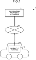
- FIG. 1 is a block diagram illustrating a configuration of an information providing system 1 according to a first embodiment.
- the information providing system 1 is a system that provides, to a passenger PA (see FIG. 5 ) in a vehicle VE ( FIG. 1 ) that is a moving body, object information on an object (for example, a name of the object), such as a building, that is present around the vehicle VE.
- This information providing system 1 includes, as illustrated in FIG. 1 , an in-vehicle terminal 2 and an information providing apparatus 3.
- the in-vehicle terminal 2 and the information providing apparatus 3 perform communication via a network NE ( FIG. 1 ) that is a wireless communication network.
- FIG. 1 illustrates, as an example, a case where the in-vehicle terminal 2 that performs communication with the information providing apparatus 3 is a single in-vehicle terminal, but the in-vehicle terminal 2 may include plural in-vehicle terminals respectively installed in plural vehicles. Furthermore, to provide object information to each of plural passengers riding on a single vehicle, a plurality of the in-vehicle terminals 2 may be installed in that single vehicle.
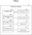
- FIG. 2 is a block diagram illustrating a configuration of the in-vehicle terminal 2.
- the in-vehicle terminal 2 is, for example, a stationary navigation device or drive recorder installed in the vehicle VE. Without being limited to the navigation device or drive recorder, a portable terminal, such as a smartphone used by the passenger PA in the vehicle VE, may be adopted as the in-vehicle terminal 2.
- This in-vehicle terminal 2 includes, as illustrated in FIG. 2 , a voice input unit 21, a voice output unit 22, an imaging unit 23, a display unit 24, and a terminal body 25.
- the voice input unit 21 includes a microphone 211 (see FIG. 5 ) to which voice is input and which converts the voice into an electric signal, and the voice input unit 21 generates voice information by performing analog/digital (A/D) conversion of the electric signal, for example.
- the voice information generated by the voice input unit 21 is a digital signal.
- the voice input unit 21 then outputs the voice information to the terminal body 25.
- the voice output unit 22 includes a speaker 221 (see FIG. 5 ), converts a digital voice signal input from the terminal body 25 into an analog voice signal by digital/analog (D/A) conversion, and outputs voice corresponding to the analog voice signal from the speaker 221.
- a speaker 221 see FIG. 5
- D/A digital/analog
- the imaging unit 23 Under control of the terminal body 25, the imaging unit 23 generates a captured image by capturing an image of surroundings of the vehicle VE. The imaging unit 23 then outputs the generated captured image to the terminal body 25.
- the display unit 24 includes a display using liquid crystal or organic electroluminescence (EL), for example, and displays various images under control of the terminal body 25.
- EL organic electroluminescence
- the terminal body 25 includes, as illustrated in FIG. 2 , a communication unit 251, a control unit 252, and a storage unit 253.
- the communication unit 251 transmits and receives information to and from the information providing apparatus 3 via the network NE.
- the control unit 252 is implemented by a controller, such as a central processing unit (CPU) or a microprocessing unit (MPU), executing various programs stored in the storage unit 253, and controls the overall operation of the in-vehicle terminal 2.
- a controller such as a central processing unit (CPU) or a microprocessing unit (MPU), executing various programs stored in the storage unit 253, and controls the overall operation of the in-vehicle terminal 2.
- the control unit 252 may be formed of an integrated circuit, such as an application specific integrated circuit (ASIC) or a field programmable gate array (FPGA).
- ASIC application specific integrated circuit
- FPGA field programmable gate array
- the storage unit 253 stores therein, for example, various programs executed by the control unit 252 and data needed for the control unit 252 to perform processing.
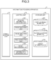
- FIG. 3 is a block diagram illustrating a configuration of the information providing apparatus 3.
- the information providing apparatus 3 is, for example, a server apparatus.
- This information providing apparatus 3 includes, as illustrated in FIG. 3 , a communication unit 31, a control unit 32, and a storage unit 33.
- the communication unit 31 transmits and receives information to and from the in-vehicle terminal 2 (the communication unit 251) via the network NE.
- the control unit 32 is implemented by a controller, such as a CPU or an MPU, executing various programs (including an information providing program according to this embodiment) stored in the storage unit 33, and controls the overall operation of the information providing apparatus 3.
- the control unit 32 may be formed of an integrated circuit, such as an ASIC or FPGA.
- This control unit 32 includes, as illustrated in FIG. 3 , a request information obtaining unit 321, a voice analyzing unit 322, an image obtaining unit 323, an area extracting unit 324, an object recognizing unit 325, and an information providing unit 326.
- the request information obtaining unit 321 obtains request information that is from the passenger PA of the vehicle VE requesting object information to be provided.
- the request information is voice information generated by the voice input unit 21 on the basis of voice captured by the voice input unit 21, the voice being a word or words spoken by the passenger PA in the vehicle VE. That is, the request information obtaining unit 321 obtains the request information (the voice information) from the in-vehicle terminal 2 via the communication unit 31.
- the voice analyzing unit 322 analyzes the request information (voice information) obtained by the request information obtaining unit 321.
- the image obtaining unit 323 obtains a captured image generated by the imaging unit 23 from the in-vehicle terminal 2 via the communication unit 31.
- the area extracting unit 324 extracts (predicts) an area of interest on which a line of sight is focused (the line of sight tends to be focused) in the captured image obtained by the image obtaining unit 323.
- the area extracting unit 324 extracts the area of interest in the captured image by using a so-called visual salience technique. More specifically, the area extracting unit 324 extracts the area of interest in the captured image by image recognition (image recognition using artificial intelligence (AI)) using a first learning model described below.
- AI artificial intelligence
- the first learning model is a model obtained by machine learning (for example, deep learning) areas using training images that are images including the areas that have been identified by use of an eye tracker as areas on which lines of sight of a subject are focused, the areas having been labelled beforehand.
- machine learning for example, deep learning
- the object recognizing unit 325 recognizes an object included in an area of interest that is in a captured image and that has been extracted by the area extracting unit 324.
- the object recognizing unit 325 recognizes the object included in the area of interest in the captured image by image recognition (image recognition using AI) using a second learning model described below.
- the second learning model is a model obtained by machine learning (for example, deep learning) features of various objects including animals, mountains, rivers, lakes, and facilities, on the basis of training images that are captured images including these various objects captured therein.
- machine learning for example, deep learning
- the information providing unit 326 provides object information related to an object recognized by the object recognizing unit 325. More specifically, the information providing unit 326 reads the object information corresponding to the object recognized by the object recognizing unit 325 from an object information database (DB) 333 in the storage unit 33. The information providing unit 326 then transmits the object information to the in-vehicle terminal 2 via the communication unit 31.
- DB object information database
- the storage unit 33 stores, in addition to the various programs (the information providing program according to this embodiment) executed by the control unit 32, data needed for the control unit 32 to perform processing, for example.
- This storage unit 33 includes, as illustrated in FIG. 3 , a first learning model DB 331, a second learning model DB 332, and the object information DB 333.
- the first learning model DB 331 stores therein the first learning model described above.
- the second learning model DB 332 stores therein the second learning model described above.
- the object information DB 333 stores therein the object information described above.
- the object information DB 333 stores therein plural pieces of object information associated with various objects.
- a piece of object information is information describing an object, such as a name of the object, and includes text data, voice data, or image data.
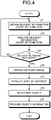
- FIG. 4 is a flowchart illustrating the information providing method.
- FIG. 5 is a diagram for explanation of the information providing method. Specifically, FIG. 5 is a diagram illustrating a captured image IM generated by the imaging unit 23 and obtained at Step S4.
- FIG. 5 illustrates, as an example, a case where the imaging unit 23 has been installed in the vehicle VE such that an image of a front view from the vehicle VE is captured through a windshield from the interior of the vehicle VE.
- FIG. 5 illustrates, as an example, a case where the passenger PA sitting in the front passenger seat of the vehicle VE is included as a subject in the captured image IM.
- FIG. 5 illustrates, as an example, a case where the passenger PA is speaking words, "What's that?".
- the imaging unit 23 is not necessarily installed at the position described above.
- the imaging unit 23 may be installed in the vehicle VE such that an image of the left view, the right view, or the rear view from the vehicle VE is captured, or may be installed outside the vehicle VE such that an image of surroundings of the vehicle VE is captured.
- a passenger in a vehicle according to this embodiment is not necessarily a passenger sitting in the front passenger seat of the vehicle VE and includes, for example, a passenger sitting in the driver's seat or a rear seat.
- a plurality of the imaging units 23 may be provided instead of just one.
- the request information obtaining unit 321 obtains request information (voice information) from the in-vehicle terminal 2 via the communication unit 31 (Step S1).
- Step S2 the voice analyzing unit 322 analyzes the request information (the voice information) obtained at Step S1 (Step S2).
- Step S2 the voice analyzing unit 322 determines whether or not a specific keyword or keywords is/are included in the request information (voice information) as a result of analyzing the request information (the voice information) at Step S2 (Step S3).
- the specific keyword or keywords is/are a word or words of the passenger PA in the vehicle VE requesting object information to be provided, and examples of the specific keyword or keywords include "What's that?”, "Could you tell me what that is?", " What can that be?”, and "Can you tell me?”.
- Step S3 In a case where it has been determined that the specific keyword or keywords is/are not included (Step S3: No), the control unit 32 returns to Step S1.
- Step S3 the image obtaining unit 323 obtains the captured image IM generated by the imaging unit 23 from the in-vehicle terminal 2 via the communication unit 31 (Step S4: an image obtaining step).
- the image obtaining unit 323 is configured to obtain the captured image IM generated by the imaging unit 23 from the in-vehicle terminal 2 via the communication unit 31 at the time when the passenger PA in the vehicle VE speaks the words, "What's that?" (Step S3: Yes), but the embodiment is not limited to this example.
- the information providing apparatus 3 sequentially obtains captured images generated by the imaging unit 23 from the in-vehicle terminal 2 via the communication unit 31.
- the image obtaining unit 323 may be configured to obtain, from the sequentially obtained captured images, a captured image to be used in processing from Step S4, the captured image being a captured image obtained at the time when the passenger PA in the vehicle VE speaks the words, "What's that?" (Step S3: Yes).
- Step S4 the area extracting unit 324 extracts an area of interest Ar1 ( FIG. 5 ) on which a line of sight is focused in the captured image IM by image recognition using the first learning model stored in the first learning model DB 331 (Step S5: an area extracting step) .
- Step S5 the object recognizing unit 325 recognizes, in the captured image IM, an object OB1 included in the area of interest Ar1 extracted at Step S5 by image recognition using the second learning model stored in the second learning model DB 332 (Step S6: an object recognizing step).
- Step S6 the information providing unit 326 reads object information corresponding to the object OB1 recognized at Step S6 from the object information DB 333 and transmits the object information to the in-vehicle terminal 2 via the communication unit 31 (Step S7: an information providing step).
- the control unit 252 controls operation of at least any of the voice output unit 22 and display unit 24 and informs the passenger PA in the vehicle VE of the object information transmitted from the information providing apparatus 3 by at least any of voice, text, and an image.
- the object OB1 is "Moulin Rouge”
- the passenger PA in the vehicle VE is informed of the object information, "That is Moulin Rouge. Glamous dancing shows are held at night there.”, for example, by voice.
- the object OB1 is an animal, a buffalo, instead of a building, the passenger PA in the vehicle VE is informed of the object information, "That is a buffalo. Buffaloes move around in herds.”, for example, by voice.
- the information providing apparatus 3 obtains the captured image IM by capturing an image of surroundings of the vehicle VE and extracts the area of interest Ar1 on which a line of sight is focused in the captured image IM.
- the information providing apparatus 3 recognizes the object OB1 included in the area of interest Ar1 in the captured image IM and transmits object information related to the object OB1 to the in-vehicle terminal 2.
- the passenger PA in the vehicle VE and desiring to obtain the object information related to the object OB1 recognizes the object information related to the object OB1 by being informed of the object information from the in-vehicle terminal 2.
- the information providing apparatus 3 extracts the area of interest Ar1 on which a line of sight is focused in the captured image IM by using the so-called visual salience technique. Therefore, even if the passenger PA in the vehicle VE does not point the passenger PA's hand or finger to the object OB1, the area including the object OB1 is able to be extracted accurately as the area of interest Ar1.
- the information providing apparatus 3 provides the object information in response to request information that is from the passenger PA in the vehicle VE requesting the object information to be provided. Therefore, as compared to a configuration that constantly provides object information regardless of the request information, the processing load on the information providing apparatus 3 is able to be reduced.
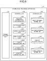
- FIG. 6 is a block diagram illustrating a configuration of an information providing apparatus 3A according to the second embodiment.
- the information providing apparatus 3A has, as illustrated in FIG. 6 , functions of a posture detecting unit 327 in the control unit 32, additionally to the information providing apparatus 3 (see FIG. 3 ) described above with respect to the first embodiment. Furthermore, functions of the object recognizing unit 325 have been modified in the information providing apparatus 3A. An object recognizing unit according to the second embodiment will hereinafter be referred to as an object recognizing unit 325A (see FIG. 6 ) for convenience of explanation. In addition, the information providing apparatus 3A has a third learning model DB 334 (see FIG. 6 ) added in the storage unit 33.
- the posture detecting unit 327 detects a posture of a passenger PA in a vehicle VE.
- the posture detecting unit 327 detects the posture by so-called skeleton detection. More specifically, the posture detecting unit 327 detects the posture of the passenger PA in the vehicle VE by detecting the skeleton of the passenger PA included as a subject in a captured image IM, through image recognition (image recognition using AI) using a third learning model described below.
- the third learning model is a model obtained by machine learning (for example, deep learning) positions of joints of a person captured in captured images, on the basis of training images that are images having these positions labelled beforehand for the captured images.
- machine learning for example, deep learning
- the third learning model DB 334 stores therein the third learning model.
- the object recognizing unit 325A has a function (hereinafter, referred to as an additional function) executed in a case where plural areas of interest have been extracted in the captured image IM by the area extracting unit 324, in addition to functions that are the same as those of the object recognizing unit 325 described above with respect to the first embodiment.
- This additional function is as follows.
- the object recognizing unit 325A identifies any one area of interest of the plural areas of interest on the basis of a posture of the passenger PA detected by the posture detecting unit 327. Similarly to the object recognizing unit 325 described above with respect to the first embodiment, the object recognizing unit 325A recognizes an object included in the identified one area of interest in the captured image IM by image recognition using the second learning model.
- FIG. 7 is a flowchart illustrating the information providing method.
- FIG. 8 is a diagram for explanation of the information providing method. Specifically, FIG. 8 is a diagram corresponding to FIG. 5 and illustrates the captured image IM generated by the imaging unit 23 and obtained at Step S4.
- Steps S6A1 to S6A3 have been added to the information providing method (see FIG. 4 ) described above with respect to the first embodiment. Therefore, only Steps S6A1 to S6A3 will be described mainly below. Steps S6A1 to S6A3 and S6 correspond to an object recognizing step according to this embodiment.
- Step S6A1 is executed after Step S5.
- control unit 32 determines whether or not the number of areas of interest extracted at Step S5 is plural at Step S6A1.
- FIG. 8 illustrates, as an example, a case where three areas of interest Ar1 to Ar3 have been extracted at Step S5.
- Step S6A1 If it has been determined that the number of areas of interest is one (Step S6A1: No), the control unit 32 proceeds to Step S6 and recognizes an object (for example, an object OB1) included in the single area of interest (for example, the area of interest Ar1, similarly to the first embodiment described above).
- an object for example, an object OB1 included in the single area of interest (for example, the area of interest Ar1, similarly to the first embodiment described above).
- Step S6A1 if the control unit 32 has determined that the number of areas of interest is plural (Step S6A1: Yes), the control unit 32 proceeds to Step S6A2.
- the posture detecting unit 327 detects a posture of the passenger PA who is included in the captured image IM as a subject and who is in the vehicle VE, by detecting a skeleton of the passenger PA through image recognition using the third learning model stored in the third learning model DB 334.
- the object recognizing unit 325A identifies a direction DI ( FIG. 8 ) of the face FA and/or a finger FI of the passenger PA from the posture of the passenger PA detected at Step S6A2.
- the object recognizing unit 325A then identifies the one area of interest Ar2 positioned in the direction DI, with the passenger PA serving as a reference, among the three areas of interest Ar1 to Ar3 extracted at Step S5, in the captured image IM (Step S6A3).
- Step S6A3 the control unit 32 then proceeds to Step S6 and recognizes an object OB2 ( FIG. 8 ) included in that one area of interest Ar2.
- the second embodiment described above has the following effects, in addition to effects similar to the above described effects of the first embodiment.
- the information providing apparatus 3A detects a posture of the passenger PA in the vehicle VE and identifies the one area of interest Ar2 from the plural areas of interest Ar1 to Ar3 on the basis of the posture. The information providing apparatus 3 then recognizes the object OB2 included in the identified area of interest Ar2.
- the area including the object OB2 for which the passenger PA in the vehicle VE desires to obtain object information is able to be identified as the area of interest Ar1 accurately. Therefore, an appropriate piece of object information is able to be provided to the passenger PA in the vehicle VE.
- the information providing apparatus 3A detects a posture of the passenger PA in the vehicle VE by the so-called skeleton detection. Therefore, the posture is able to be detected highly accurately, and even in a case where the plural areas of interest Ar1 to Ar3 have been extracted in the captured image IM, an appropriate piece of object information is able to be provided to the passenger PA in the vehicle VE.
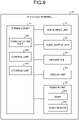
- FIG. 9 is a block diagram illustrating a configuration of an in-vehicle terminal 2B according to a third embodiment.
- the in-vehicle terminal 2B according to this third embodiment has, as illustrated in FIG. 9 , a sensor unit 26, added in the in-vehicle terminal 2 (see FIG. 2 ) described above with respect to the first embodiment.
- the sensor unit 26 includes, as illustrated in FIG. 9 , a lidar 261 and a global navigation satellite system (GNSS) sensor 262.
- GNSS global navigation satellite system
- the lidar 261 discretely measures distance to an object that is present in one's external environment, recognizes a surface of the object as a three-dimensional point group, and generates point group data.
- any other external sensor such as a milliwave radar or a sonar, which is a sensor that is able to measure the distance to the object present in the external environment, may be adopted.
- the GNSS sensor 262 receives radio waves including position measurement data transmitted from a navigation satellite by using a GNSS.
- the position measurement data is used to detect an absolute position of a vehicle VE from latitude and longitude information, for example, and corresponds to positional information according to this embodiment.
- the GNSS used may be a global positioning system (GPS), for example, or any other system.
- the sensor unit 26 then outputs output data, such as the point group data and the position measurement data, to the terminal body 25.
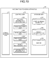
- FIG. 10 is a block diagram illustrating a configuration of an information providing apparatus 3B according to the third embodiment.
- Functions of the object recognizing unit 325 in the information providing apparatus 3B according to this third embodiment have been modified from those of the information providing apparatus 3 (see FIG. 3 ) described above with respect to the first embodiment.
- An object recognizing unit according to the third embodiment will hereinafter be referred to as an object recognizing unit 325B (see FIG. 10 ) for convenience of explanation.
- the information providing apparatus 3B has the second learning model DB 332 omitted and a map DB 335 (see FIG. 10 ) added, in the storage unit 33.
- the map DB 335 stores therein map data.
- the map data includes, for example: road data represented by links corresponding to roads and nodes corresponding to junctions (intersections) between roads; and facility information having facilities and positions of the facilities (hereinafter, referred to as facility positions) associated with each other respectively.
- the object recognizing unit 325B obtains output data (point group data generated by the lidar 261 and position measurement data received by the GNSS sensor 262) of the sensor unit 26 from the in-vehicle terminal 2 via the communication unit 31.
- the object recognizing unit 325B then recognizes an object included in an area of interest extracted by the area extracting unit 324, in a captured image IM, on the basis of the output data, the captured image IM, and the map data stored in the map DB 335.
- the object recognizing unit 325B described above corresponds to a positional information obtaining unit and a facility information obtaining unit, in addition to an object recognizing unit according to this embodiment.
- FIG. 11 is a flowchart illustrating the information providing method.
- the information providing method according to this third embodiment has, as illustrated in FIG. 11 , Steps S6B1 to S6B5 added to the information providing method (see FIG. 4 ) described above with respect to the first embodiment, instead of Step S6. Therefore, only Steps S6B1 to S6B5 will be described mainly below. These steps S6B1 to S6B5 correspond to an object recognizing step according to this embodiment.
- Step S6B1 is executed after Step S5.
- the object recognizing unit 325B obtains output data (point group data generated by the lidar 261 and position measurement data generated by the GNSS sensor 262) of the sensor unit 26 from the in-vehicle terminal 2 via the communication unit 31.
- the object recognizing unit 325B is configured to obtain the output data of the sensor unit 26 from the in-vehicle terminal 2 via the communication unit 31 at the time when a passenger PA in the vehicle VE speaks words including a specific keyword or keywords (Step S3: Yes), but the embodiment is not limited to this example.
- the information providing apparatus 3B sequentially obtains sets of output data of the sensor unit 26 from the in-vehicle terminal 2 via the communication unit 31.
- the object recognizing unit 325B may be configured to obtain, from the sequentially obtained sets of output data, a set of output data to be used in processing from Step S6B1, the set of output data being a set of output data obtained at the time when the passenger PA in the vehicle VE speaks words including a specific keyword or keywords (Step S3: Yes).
- Step S6B1 the object recognizing unit 325B estimates a position of the vehicle VE on the basis of the output data obtained at Step S6B1 (the position measurement data received by the GNSS sensor 262) and the map data stored in the map DB 335 (Step S6B2).
- the object recognizing unit 325B estimates a position of an object included in an area of interest that has been extracted at Step S5 and that is in the captured image IM (Step S6B3).
- the object recognizing unit 325B estimates the position of the object by using the output data (the point group data) obtained at Step S6B1, the position of the vehicle VE estimated at Step S6B2, and the position of the area of interest that has been extracted at Step S5 and that is in the captured image IM.
- the object recognizing unit 325B obtains facility information including a facility position that is approximately the same as the position of the object estimated at Step S6B3, from the map DB 335 (Step S6B4).
- Step S6B4 the object recognizing unit 325B recognizes, as the object included in the area of interest that has been extracted at Step S5 and that is in the captured image IM, a facility included in the facility information obtained at Step S6B4 (Step S6B5).
- the control unit 32 then proceeds to Step S7 after Step S6B5.
- the third embodiment described above has the following effects, in addition to effects similar to the above described effects of the first embodiment.
- the information providing apparatus 3B recognizes an object included in an area of interest in the captured image IM on the basis of positional information (position measurement data received by the GNSS sensor 262) and facility information. In other words, the information providing apparatus 3B recognizes the object included in the area of interest in the captured image IM on the basis of information (positional information and facility information) widely used in navigation equipment.
- FIG. 12 is a block diagram illustrating a configuration of an information providing apparatus 3C according to the fourth embodiment.
- Functions of the object recognizing unit 325 and information providing unit 326 have been modified in the information providing apparatus 3C according to the fourth embodiment, as illustrated in FIG. 12 , from those of the information providing apparatus 3 (see FIG. 3 ) described above with respect to the first embodiment.
- An object recognizing unit according to the fourth embodiment will hereinafter be referred to as an object recognizing unit 325C (see FIG. 12 ), and an information providing unit according to the fourth embodiment as an information providing unit 326C (see FIG. 12 ), for convenience of explanation.
- the object recognizing unit 325C has a function (hereinafter, referred to as an additional function) executed in a case where plural areas of interest have been extracted in a captured image IM by the area extracting unit 324, in addition to functions that are the same as those of the object recognizing unit 325 described above with respect to the first embodiment.
- This additional function is as follows.
- the object recognizing unit 325C recognizes objects respectively included in the plural areas of interest in the captured image IM, by image recognition using the second learning model.
- the information providing unit 326C has a function (hereinafter, referred to as an additional function) executed in the case where plural areas of interest have been extracted in the captured image IM by the area extracting unit 324, in addition to functions that are the same as those of the information providing unit 326 described above with respect to the first embodiment.
- This additional function is as follows.
- the information providing unit 326C identifies one object of the objects recognized by the object recognizing unit 325C on the basis of a result of analysis by the voice analyzing unit 322 and object information stored in the object information DB 333.
- the information providing unit 326C then transmits object information corresponding to that one object identified, to the in-vehicle terminal 2 via the communication unit 31.
- FIG. 13 is a flowchart illustrating the information providing method.
- FIG. 14 is a diagram for explanation of the information providing method. Specifically, FIG. 14 is a diagram corresponding to FIG. 5 and illustrates the captured image IM generated by the imaging unit 23 and obtained at Step S4. Differently from the example in FIG. 5 , FIG. 14 illustrates, as an example, a case where a passenger PA sitting in the front passenger seat of a vehicle VE is speaking words, "What's that red building?".
- the information providing method according to this fourth embodiment has, as illustrated in FIG. 13 , Steps S6C1, S6C2, and S7C added to the information providing method (see FIG. 4 ) described above with respect to the first embodiment. Therefore, only Steps S6C1, S6C2, and S7C will be described mainly below. Steps S6C1, S6C2, and Step S6 each correspond to an object recognizing step according to this embodiment. Furthermore, Steps S7C and Step S7 each correspond to an information providing step according to this embodiment.
- Step S6C1 is executed after Step S5.
- Step S6C1 the control unit 32 determines whether or not the number of areas of interest extracted at Step S5 is plural, similarly to Step S6A1 described above with respect to the second embodiment.
- FIG. 14 illustrates, as an example, a case where three areas of interest Ar1 to Ar3 have been extracted at Step S5, similarly to FIG. 8 .
- Step S6C1 If it has been determined that the number of areas of interest is one (Step S6C1: No), the control unit 32 proceeds to Step S6 and recognizes an object (for example, an object OB1) included in that single area of interest (for example, the area of interest Ar1, similarly to the first embodiment described above).
- an object for example, an object OB1 included in that single area of interest (for example, the area of interest Ar1, similarly to the first embodiment described above).
- Step S6C1 if it has been determined that the number of areas of interest is plural (Step S6C1: Yes), the control unit 32 proceeds to Step S6C2.
- the object recognizing unit 325C then recognizes objects OB1 to OB3 respectively included in the three areas of interest Ar1 to Ar3 extracted at Step S5, in the captured image IM, by image recognition using the second learning model stored in the second learning model DB 332 (Step S6C2).
- Step S6C2 the information providing unit 326C executes Step S7C.
- the information providing unit 326C identifies one object of the objects recognized at Step S6C2.
- the information providing unit 326C identifies the one object on the basis of: an attribute or attributes of an object included in request information (voice information); and three pieces of object information respectively corresponding to the objects OB1 to OB3 recognized at Step S6C2, the three pieces of object information being from object information stored in the object information DB 333.
- the attribute/attributes of the object included in the request information is/are generated by analysis of the request information (the voice information) at Step S2.
- the word, "red”, and the word, "building” are the attributes of the object.
- an attribute or attributes of an object is/are information indicating any of the color, such as red, the shape, such as quadrilateral, and the type, such as building.
- the information providing unit 326C then identifies, at Step S7C, one object (for example, the object OB3) corresponding to the piece of object information including text data, "red” and "building", by referring to the three pieces of object information respectively corresponding to the objects OB1 to OB3. Furthermore, the information providing unit 326C then transmits the piece of object information corresponding to the one object identified, to the in-vehicle terminal 2 via the communication unit 31.
- one object for example, the object OB3
- the information providing unit 326C transmits the piece of object information corresponding to the one object identified, to the in-vehicle terminal 2 via the communication unit 31.
- the fourth embodiment described above has the following effects, in addition to effects similar to the above described effects of the first embodiment.
- the information providing apparatus 3C provides a piece of object information related to one object of the objects OB1 to OB3 respectively included in these plural areas of interest Ar1 to Ar3 on the basis of a result of analysis of request information (voice information).
- the object OB3 for which the passenger PA in the vehicle VE desires to obtain object information is able to be identified accurately. Therefore, an appropriate piece of object information is able to be provided to the passenger PA in the vehicle VE.
- the above described information providing apparatuses 3, and 3A to 3C according to the first to fourth embodiments each execute the processing triggered by obtainment of request information (voice information) including a specific keyword or keywords, the processing including the image obtaining step, the area extracting step, the object recognizing step, and the information providing step.
- an information providing apparatus may be configured to execute the processing constantly without obtaining request information (voice information) including a specific keyword or keywords.
- request information according to an embodiment is not necessarily voice information, and may be operation information according to an operation by a passenger PA in a vehicle VE, the operation being on an operating unit, such as a switch, provided in the in-vehicle terminal 2 or 2B.
- all of the components of any of the information providing apparatuses 3 and 3A to 3C may be provided in the in-vehicle terminal 2 or 2B.
- the in-vehicle terminal 2 or 2B corresponds to an information providing apparatus according to an embodiment.
- some of functions of the control unit 32 and a part of the storage unit 33, in any of the information providing apparatuses 3 and 3A to 3C may be provided in the in-vehicle terminal 2 or 2B.
- the whole information providing system 1 corresponds to an information providing apparatus according to an embodiment.
Landscapes
- Engineering & Computer Science (AREA)
- Physics & Mathematics (AREA)
- General Physics & Mathematics (AREA)
- Theoretical Computer Science (AREA)
- Remote Sensing (AREA)
- Radar, Positioning & Navigation (AREA)
- Multimedia (AREA)
- Computer Vision & Pattern Recognition (AREA)
- Automation & Control Theory (AREA)
- Human Computer Interaction (AREA)
- Traffic Control Systems (AREA)
- Navigation (AREA)
- Image Analysis (AREA)
Abstract
Description
- The present invention relates to an information providing apparatus, an information providing method, an information providing program, and a storage medium. Background
- A conventionally known target identifying apparatus identifies a target that is present around a vehicle and reads out information, such as a name related to the target, by voice (for example, see Patent Literature 1).
- The target identifying apparatus described in
Patent Literature 1 identifies a facility, for example, as the target, the facility being on a map and present in a pointing direction to which a passenger in the vehicle is pointing with the passenger's hand or finger. - Patent Literature 1:
Japanese Unexamined Patent Application Publication No. 2007-080060 - However, the technique described in
Patent Literature 1 has a problem, for example, of not being able to improve user-friendliness because the passenger in the vehicle is required to perform the operation of pointing the hand or finger at the target, the passenger desiring to obtain information related to the target. - The present invention has been made in view of the above and an object thereof is to provide an information providing apparatus, an information providing method, an information providing program, and a storage medium that enable user-friendliness to be improved, for example.
- An information providing apparatus, includes an image obtaining unit that obtains a captured image having, captured therein, surroundings of a moving body; an area extracting unit that extracts an area of interest on which a line of sight is focused in the captured image; an object recognizing unit that recognizes an object included in the area of interest in the captured image; and an information providing unit that provides object information related to the object included in the area of interest.
- An information providing method executed by an information providing apparatus, the information providing method includes obtaining a captured image having, captured therein, surroundings of a moving body; an area extracting step of extracting an area of interest on which a line of sight is focused in the captured image; an object recognizing step of recognizing an object included in the area of interest in the captured image; and an information providing step of providing object information related to the object included in the area of interest.
- An information providing program for causing a computer, executes an image obtaining step of obtaining a captured image having, captured therein, surroundings of a moving body; an area extracting step of extracting an area of interest on which a line of sight is focused in the captured image; an object recognizing step of recognizing an object included in the area of interest in the captured image; and an information providing step of providing object information related to the object included in the area of interest.
- A storage medium storing therein an information providing program for causing a computer, executes an image obtaining step of obtaining a captured image having, captured therein, surroundings of a moving body; an area extracting step of extracting an area of interest on which a line of sight is focused in the captured image; an object recognizing step of recognizing an object included in the area of interest in the captured image; and an information providing step of providing object information related to the object included in the area of interest.
-
-
FIG. 1 is a block diagram illustrating a configuration of an information providing system according to a first embodiment. -
FIG. 2 is a block diagram illustrating a configuration of an in-vehicle terminal. -
FIG. 3 is a block diagram illustrating a configuration of an information providing apparatus. -
FIG. 4 is a flowchart illustrating an information providing method. -
FIG. 5 is a diagram for explanation of the information providing method. -
FIG. 6 is a block diagram illustrating a configuration of an information providing apparatus according to a second embodiment. -
FIG. 7 is a flowchart illustrating an information providing method. -
FIG. 8 is a diagram for explanation of the information providing method. -
FIG. 9 is a block diagram illustrating a configuration of an in-vehicle terminal according to a third embodiment. -
FIG. 10 is a block diagram illustrating a configuration of an information providing apparatus according to the third embodiment. -
FIG. 11 is a flowchart illustrating an information providing method. -
FIG. 12 is a block diagram illustrating a configuration of an information providing apparatus according to a fourth embodiment. -
FIG. 13 is a flowchart illustrating an information providing method. -
FIG. 14 is a diagram for explanation of the information providing method. - Modes for implementing the present invention (hereinafter, embodiments) will be described below while reference is made to the drawings. The present invention is not limited by the embodiments described below. Furthermore, any portions that are the same will be assigned with the same reference sign, throughout the drawings.
-
FIG. 1 is a block diagram illustrating a configuration of aninformation providing system 1 according to a first embodiment. - The
information providing system 1 is a system that provides, to a passenger PA (seeFIG. 5 ) in a vehicle VE (FIG. 1 ) that is a moving body, object information on an object (for example, a name of the object), such as a building, that is present around the vehicle VE. Thisinformation providing system 1 includes, as illustrated inFIG. 1 , an in-vehicle terminal 2 and aninformation providing apparatus 3. The in-vehicle terminal 2 and theinformation providing apparatus 3 perform communication via a network NE (FIG. 1 ) that is a wireless communication network. -
FIG. 1 illustrates, as an example, a case where the in-vehicle terminal 2 that performs communication with theinformation providing apparatus 3 is a single in-vehicle terminal, but the in-vehicle terminal 2 may include plural in-vehicle terminals respectively installed in plural vehicles. Furthermore, to provide object information to each of plural passengers riding on a single vehicle, a plurality of the in-vehicle terminals 2 may be installed in that single vehicle. -
FIG. 2 is a block diagram illustrating a configuration of the in-vehicle terminal 2. - The in-
vehicle terminal 2 is, for example, a stationary navigation device or drive recorder installed in the vehicle VE. Without being limited to the navigation device or drive recorder, a portable terminal, such as a smartphone used by the passenger PA in the vehicle VE, may be adopted as the in-vehicle terminal 2. This in-vehicle terminal 2 includes, as illustrated inFIG. 2 , avoice input unit 21, avoice output unit 22, an imaging unit 23, adisplay unit 24, and a terminal body 25. - The
voice input unit 21 includes a microphone 211 (seeFIG. 5 ) to which voice is input and which converts the voice into an electric signal, and thevoice input unit 21 generates voice information by performing analog/digital (A/D) conversion of the electric signal, for example. In this first embodiment, the voice information generated by thevoice input unit 21 is a digital signal. Thevoice input unit 21 then outputs the voice information to the terminal body 25. - The
voice output unit 22 includes a speaker 221 (seeFIG. 5 ), converts a digital voice signal input from the terminal body 25 into an analog voice signal by digital/analog (D/A) conversion, and outputs voice corresponding to the analog voice signal from thespeaker 221. - Under control of the terminal body 25, the imaging unit 23 generates a captured image by capturing an image of surroundings of the vehicle VE. The imaging unit 23 then outputs the generated captured image to the terminal body 25.
- The
display unit 24 includes a display using liquid crystal or organic electroluminescence (EL), for example, and displays various images under control of the terminal body 25. - The terminal body 25 includes, as illustrated in
FIG. 2 , a communication unit 251, a control unit 252, and astorage unit 253. - Under control of the control unit 252, the communication unit 251 transmits and receives information to and from the
information providing apparatus 3 via the network NE. - The control unit 252 is implemented by a controller, such as a central processing unit (CPU) or a microprocessing unit (MPU), executing various programs stored in the
storage unit 253, and controls the overall operation of the in-vehicle terminal 2. Without being limited to the CPU or MPU, the control unit 252 may be formed of an integrated circuit, such as an application specific integrated circuit (ASIC) or a field programmable gate array (FPGA). - The
storage unit 253 stores therein, for example, various programs executed by the control unit 252 and data needed for the control unit 252 to perform processing. -
FIG. 3 is a block diagram illustrating a configuration of theinformation providing apparatus 3. - The
information providing apparatus 3 is, for example, a server apparatus. Thisinformation providing apparatus 3 includes, as illustrated inFIG. 3 , acommunication unit 31, acontrol unit 32, and astorage unit 33. - Under control of the
control unit 32, thecommunication unit 31 transmits and receives information to and from the in-vehicle terminal 2 (the communication unit 251) via the network NE. - The
control unit 32 is implemented by a controller, such as a CPU or an MPU, executing various programs (including an information providing program according to this embodiment) stored in thestorage unit 33, and controls the overall operation of theinformation providing apparatus 3. Without being limited to the CPU or MPU, thecontrol unit 32 may be formed of an integrated circuit, such as an ASIC or FPGA. Thiscontrol unit 32 includes, as illustrated inFIG. 3 , a requestinformation obtaining unit 321, avoice analyzing unit 322, animage obtaining unit 323, anarea extracting unit 324, anobject recognizing unit 325, and aninformation providing unit 326. - The request
information obtaining unit 321 obtains request information that is from the passenger PA of the vehicle VE requesting object information to be provided. In this first embodiment, the request information is voice information generated by thevoice input unit 21 on the basis of voice captured by thevoice input unit 21, the voice being a word or words spoken by the passenger PA in the vehicle VE. That is, the requestinformation obtaining unit 321 obtains the request information (the voice information) from the in-vehicle terminal 2 via thecommunication unit 31. - The
voice analyzing unit 322 analyzes the request information (voice information) obtained by the requestinformation obtaining unit 321. - The
image obtaining unit 323 obtains a captured image generated by the imaging unit 23 from the in-vehicle terminal 2 via thecommunication unit 31. - The
area extracting unit 324 extracts (predicts) an area of interest on which a line of sight is focused (the line of sight tends to be focused) in the captured image obtained by theimage obtaining unit 323. In this first embodiment, thearea extracting unit 324 extracts the area of interest in the captured image by using a so-called visual salience technique. More specifically, thearea extracting unit 324 extracts the area of interest in the captured image by image recognition (image recognition using artificial intelligence (AI)) using a first learning model described below. - The first learning model is a model obtained by machine learning (for example, deep learning) areas using training images that are images including the areas that have been identified by use of an eye tracker as areas on which lines of sight of a subject are focused, the areas having been labelled beforehand.
- The
object recognizing unit 325 recognizes an object included in an area of interest that is in a captured image and that has been extracted by thearea extracting unit 324. In this first embodiment, theobject recognizing unit 325 recognizes the object included in the area of interest in the captured image by image recognition (image recognition using AI) using a second learning model described below. - The second learning model is a model obtained by machine learning (for example, deep learning) features of various objects including animals, mountains, rivers, lakes, and facilities, on the basis of training images that are captured images including these various objects captured therein.
- The
information providing unit 326 provides object information related to an object recognized by theobject recognizing unit 325. More specifically, theinformation providing unit 326 reads the object information corresponding to the object recognized by theobject recognizing unit 325 from an object information database (DB) 333 in thestorage unit 33. Theinformation providing unit 326 then transmits the object information to the in-vehicle terminal 2 via thecommunication unit 31. - The
storage unit 33 stores, in addition to the various programs (the information providing program according to this embodiment) executed by thecontrol unit 32, data needed for thecontrol unit 32 to perform processing, for example. Thisstorage unit 33 includes, as illustrated inFIG. 3 , a firstlearning model DB 331, a secondlearning model DB 332, and theobject information DB 333. - The first
learning model DB 331 stores therein the first learning model described above. - The second
learning model DB 332 stores therein the second learning model described above. - The
object information DB 333 stores therein the object information described above. Theobject information DB 333 stores therein plural pieces of object information associated with various objects. A piece of object information is information describing an object, such as a name of the object, and includes text data, voice data, or image data. - An information providing method executed by the information providing apparatus 3 (the control unit 32) will be described next.
-
FIG. 4 is a flowchart illustrating the information providing method.FIG. 5 is a diagram for explanation of the information providing method. Specifically,FIG. 5 is a diagram illustrating a captured image IM generated by the imaging unit 23 and obtained at Step S4.FIG. 5 illustrates, as an example, a case where the imaging unit 23 has been installed in the vehicle VE such that an image of a front view from the vehicle VE is captured through a windshield from the interior of the vehicle VE. Furthermore,FIG. 5 illustrates, as an example, a case where the passenger PA sitting in the front passenger seat of the vehicle VE is included as a subject in the captured image IM. In addition,FIG. 5 illustrates, as an example, a case where the passenger PA is speaking words, "What's that?". - The imaging unit 23 is not necessarily installed at the position described above. For example, the imaging unit 23 may be installed in the vehicle VE such that an image of the left view, the right view, or the rear view from the vehicle VE is captured, or may be installed outside the vehicle VE such that an image of surroundings of the vehicle VE is captured. Furthermore, a passenger in a vehicle according to this embodiment is not necessarily a passenger sitting in the front passenger seat of the vehicle VE and includes, for example, a passenger sitting in the driver's seat or a rear seat. In addition, a plurality of the imaging units 23 may be provided instead of just one.
- Firstly, the request
information obtaining unit 321 obtains request information (voice information) from the in-vehicle terminal 2 via the communication unit 31 (Step S1). - After Step S1, the
voice analyzing unit 322 analyzes the request information (the voice information) obtained at Step S1 (Step S2). - After Step S2, the
voice analyzing unit 322 determines whether or not a specific keyword or keywords is/are included in the request information (voice information) as a result of analyzing the request information (the voice information) at Step S2 (Step S3). - The specific keyword or keywords is/are a word or words of the passenger PA in the vehicle VE requesting object information to be provided, and examples of the specific keyword or keywords include "What's that?", "Could you tell me what that is?", " What can that be?", and "Can you tell me?".
- In a case where it has been determined that the specific keyword or keywords is/are not included (Step S3: No), the
control unit 32 returns to Step S1. - On the contrary, in a case where it has been determined that the specific keyword or keywords is/are included (Step S3: Yes), the
image obtaining unit 323 obtains the captured image IM generated by the imaging unit 23 from the in-vehicle terminal 2 via the communication unit 31 (Step S4: an image obtaining step). - In
FIG. 4 andFIG. 5 , theimage obtaining unit 323 is configured to obtain the captured image IM generated by the imaging unit 23 from the in-vehicle terminal 2 via thecommunication unit 31 at the time when the passenger PA in the vehicle VE speaks the words, "What's that?" (Step S3: Yes), but the embodiment is not limited to this example. For example, theinformation providing apparatus 3 sequentially obtains captured images generated by the imaging unit 23 from the in-vehicle terminal 2 via thecommunication unit 31. Theimage obtaining unit 323 may be configured to obtain, from the sequentially obtained captured images, a captured image to be used in processing from Step S4, the captured image being a captured image obtained at the time when the passenger PA in the vehicle VE speaks the words, "What's that?" (Step S3: Yes). - After Step S4, the
area extracting unit 324 extracts an area of interest Ar1 (FIG. 5 ) on which a line of sight is focused in the captured image IM by image recognition using the first learning model stored in the first learning model DB 331 (Step S5: an area extracting step) . - After Step S5, the
object recognizing unit 325 recognizes, in the captured image IM, an object OB1 included in the area of interest Ar1 extracted at Step S5 by image recognition using the second learning model stored in the second learning model DB 332 (Step S6: an object recognizing step). - After Step S6, the
information providing unit 326 reads object information corresponding to the object OB1 recognized at Step S6 from theobject information DB 333 and transmits the object information to the in-vehicle terminal 2 via the communication unit 31 (Step S7: an information providing step). The control unit 252 then controls operation of at least any of thevoice output unit 22 anddisplay unit 24 and informs the passenger PA in the vehicle VE of the object information transmitted from theinformation providing apparatus 3 by at least any of voice, text, and an image. For example, if the object OB1 is "Moulin Rouge", the passenger PA in the vehicle VE is informed of the object information, "That is Moulin Rouge. Glamourous dancing shows are held at night there.", for example, by voice. In a case where the object OB1 is an animal, a buffalo, instead of a building, the passenger PA in the vehicle VE is informed of the object information, "That is a buffalo. Buffaloes move around in herds.", for example, by voice. - The above described first embodiment has the following effects.
- The
information providing apparatus 3 according to the first embodiment obtains the captured image IM by capturing an image of surroundings of the vehicle VE and extracts the area of interest Ar1 on which a line of sight is focused in the captured image IM. Theinformation providing apparatus 3 then recognizes the object OB1 included in the area of interest Ar1 in the captured image IM and transmits object information related to the object OB1 to the in-vehicle terminal 2. As a result, the passenger PA in the vehicle VE and desiring to obtain the object information related to the object OB1 recognizes the objet information related to the object OB1 by being informed of the object information from the in-vehicle terminal 2. - Therefore, there is no need to make the passenger PA perform the conventional operation of pointing the passenger PA's hand or finger at the object OB1, the passenger PA being in the vehicle VE and desiring to obtain the object information related to the object OB1, and user-friendliness is thus able to be improved.
- In particular, the
information providing apparatus 3 extracts the area of interest Ar1 on which a line of sight is focused in the captured image IM by using the so-called visual salience technique. Therefore, even if the passenger PA in the vehicle VE does not point the passenger PA's hand or finger to the object OB1, the area including the object OB1 is able to be extracted accurately as the area of interest Ar1. - Furthermore, the
information providing apparatus 3 provides the object information in response to request information that is from the passenger PA in the vehicle VE requesting the object information to be provided. Therefore, as compared to a configuration that constantly provides object information regardless of the request information, the processing load on theinformation providing apparatus 3 is able to be reduced. - A second embodiment will be described next.
- In the following description, any component that is the same as that of the first embodiment described above will be assigned with the same reference sign, and detailed description thereof will be omitted or simplified.
-
FIG. 6 is a block diagram illustrating a configuration of aninformation providing apparatus 3A according to the second embodiment. - The
information providing apparatus 3A according to the second embodiment has, as illustrated inFIG. 6 , functions of aposture detecting unit 327 in thecontrol unit 32, additionally to the information providing apparatus 3 (seeFIG. 3 ) described above with respect to the first embodiment. Furthermore, functions of theobject recognizing unit 325 have been modified in theinformation providing apparatus 3A. An object recognizing unit according to the second embodiment will hereinafter be referred to as anobject recognizing unit 325A (seeFIG. 6 ) for convenience of explanation. In addition, theinformation providing apparatus 3A has a third learning model DB 334 (seeFIG. 6 ) added in thestorage unit 33. - The
posture detecting unit 327 detects a posture of a passenger PA in a vehicle VE. In this second embodiment, theposture detecting unit 327 detects the posture by so-called skeleton detection. More specifically, theposture detecting unit 327 detects the posture of the passenger PA in the vehicle VE by detecting the skeleton of the passenger PA included as a subject in a captured image IM, through image recognition (image recognition using AI) using a third learning model described below. - The third learning model is a model obtained by machine learning (for example, deep learning) positions of joints of a person captured in captured images, on the basis of training images that are images having these positions labelled beforehand for the captured images.
- The third
learning model DB 334 stores therein the third learning model. - The
object recognizing unit 325A has a function (hereinafter, referred to as an additional function) executed in a case where plural areas of interest have been extracted in the captured image IM by thearea extracting unit 324, in addition to functions that are the same as those of theobject recognizing unit 325 described above with respect to the first embodiment. This additional function is as follows. - That is, the
object recognizing unit 325A identifies any one area of interest of the plural areas of interest on the basis of a posture of the passenger PA detected by theposture detecting unit 327. Similarly to theobject recognizing unit 325 described above with respect to the first embodiment, theobject recognizing unit 325A recognizes an object included in the identified one area of interest in the captured image IM by image recognition using the second learning model. - An information providing method executed by the
information providing apparatus 3A will be described next. -
FIG. 7 is a flowchart illustrating the information providing method.FIG. 8 is a diagram for explanation of the information providing method. Specifically,FIG. 8 is a diagram corresponding toFIG. 5 and illustrates the captured image IM generated by the imaging unit 23 and obtained at Step S4. - In the information providing method according to this second embodiment, as illustrated in
FIG. 7 , Steps S6A1 to S6A3 have been added to the information providing method (seeFIG. 4 ) described above with respect to the first embodiment. Therefore, only Steps S6A1 to S6A3 will be described mainly below. Steps S6A1 to S6A3 and S6 correspond to an object recognizing step according to this embodiment. - Step S6A1 is executed after Step S5.
- Specifically, the
control unit 32 determines whether or not the number of areas of interest extracted at Step S5 is plural at Step S6A1.FIG. 8 illustrates, as an example, a case where three areas of interest Ar1 to Ar3 have been extracted at Step S5. - If it has been determined that the number of areas of interest is one (Step S6A1: No), the
control unit 32 proceeds to Step S6 and recognizes an object (for example, an object OB1) included in the single area of interest (for example, the area of interest Ar1, similarly to the first embodiment described above). - On the contrary, if the
control unit 32 has determined that the number of areas of interest is plural (Step S6A1: Yes), thecontrol unit 32 proceeds to Step S6A2. - At Step S6A2, the
posture detecting unit 327 then detects a posture of the passenger PA who is included in the captured image IM as a subject and who is in the vehicle VE, by detecting a skeleton of the passenger PA through image recognition using the third learning model stored in the thirdlearning model DB 334. - After Step S6A2, the
object recognizing unit 325A identifies a direction DI (FIG. 8 ) of the face FA and/or a finger FI of the passenger PA from the posture of the passenger PA detected at Step S6A2. Theobject recognizing unit 325A then identifies the one area of interest Ar2 positioned in the direction DI, with the passenger PA serving as a reference, among the three areas of interest Ar1 to Ar3 extracted at Step S5, in the captured image IM (Step S6A3). - After Step S6A3, the
control unit 32 then proceeds to Step S6 and recognizes an object OB2 (FIG. 8 ) included in that one area of interest Ar2. - The second embodiment described above has the following effects, in addition to effects similar to the above described effects of the first embodiment.
- In a case where the plural areas of interest Ar1 to Ar3 have been extracted in the captured image IM, the
information providing apparatus 3A according to the second embodiment detects a posture of the passenger PA in the vehicle VE and identifies the one area of interest Ar2 from the plural areas of interest Ar1 to Ar3 on the basis of the posture. Theinformation providing apparatus 3 then recognizes the object OB2 included in the identified area of interest Ar2. - Therefore, even in a case where the plural areas of interest Ar1 to Ar3 have been extracted in the captured image IM, the area including the object OB2 for which the passenger PA in the vehicle VE desires to obtain object information is able to be identified as the area of interest Ar1 accurately. Therefore, an appropriate piece of object information is able to be provided to the passenger PA in the vehicle VE.
- In particular, the
information providing apparatus 3A detects a posture of the passenger PA in the vehicle VE by the so-called skeleton detection. Therefore, the posture is able to be detected highly accurately, and even in a case where the plural areas of interest Ar1 to Ar3 have been extracted in the captured image IM, an appropriate piece of object information is able to be provided to the passenger PA in the vehicle VE. - A third embodiment will be described next.
- In the following description, any component that is the same as that of the first embodiment described above will be assigned with the same reference sign, and detailed description thereof will be omitted or simplified.
-
FIG. 9 is a block diagram illustrating a configuration of an in-vehicle terminal 2B according to a third embodiment. - The in-vehicle terminal 2B according to this third embodiment has, as illustrated in
FIG. 9 , asensor unit 26, added in the in-vehicle terminal 2 (seeFIG. 2 ) described above with respect to the first embodiment. - The
sensor unit 26 includes, as illustrated inFIG. 9 , a lidar 261 and a global navigation satellite system (GNSS) sensor 262. - The lidar 261 discretely measures distance to an object that is present in one's external environment, recognizes a surface of the object as a three-dimensional point group, and generates point group data. Without being limited to the lidar 261, any other external sensor, such as a milliwave radar or a sonar, which is a sensor that is able to measure the distance to the object present in the external environment, may be adopted.
- The GNSS sensor 262 receives radio waves including position measurement data transmitted from a navigation satellite by using a GNSS. The position measurement data is used to detect an absolute position of a vehicle VE from latitude and longitude information, for example, and corresponds to positional information according to this embodiment. The GNSS used may be a global positioning system (GPS), for example, or any other system.
- The
sensor unit 26 then outputs output data, such as the point group data and the position measurement data, to the terminal body 25. -
FIG. 10 is a block diagram illustrating a configuration of aninformation providing apparatus 3B according to the third embodiment. Functions of theobject recognizing unit 325 in theinformation providing apparatus 3B according to this third embodiment have been modified from those of the information providing apparatus 3 (seeFIG. 3 ) described above with respect to the first embodiment. An object recognizing unit according to the third embodiment will hereinafter be referred to as anobject recognizing unit 325B (seeFIG. 10 ) for convenience of explanation. Furthermore, theinformation providing apparatus 3B has the secondlearning model DB 332 omitted and a map DB 335 (seeFIG. 10 ) added, in thestorage unit 33. - The
map DB 335 stores therein map data. The map data includes, for example: road data represented by links corresponding to roads and nodes corresponding to junctions (intersections) between roads; and facility information having facilities and positions of the facilities (hereinafter, referred to as facility positions) associated with each other respectively. - The
object recognizing unit 325B obtains output data (point group data generated by the lidar 261 and position measurement data received by the GNSS sensor 262) of thesensor unit 26 from the in-vehicle terminal 2 via thecommunication unit 31. Theobject recognizing unit 325B then recognizes an object included in an area of interest extracted by thearea extracting unit 324, in a captured image IM, on the basis of the output data, the captured image IM, and the map data stored in themap DB 335. - The
object recognizing unit 325B described above corresponds to a positional information obtaining unit and a facility information obtaining unit, in addition to an object recognizing unit according to this embodiment. - An information providing method executed by the
information providing apparatus 3B will be described next. -
FIG. 11 is a flowchart illustrating the information providing method. - The information providing method according to this third embodiment has, as illustrated in
FIG. 11 , Steps S6B1 to S6B5 added to the information providing method (seeFIG. 4 ) described above with respect to the first embodiment, instead of Step S6. Therefore, only Steps S6B1 to S6B5 will be described mainly below. These steps S6B1 to S6B5 correspond to an object recognizing step according to this embodiment. - Step S6B1 is executed after Step S5.
- Specifically, at Step S6B1, the
object recognizing unit 325B obtains output data (point group data generated by the lidar 261 and position measurement data generated by the GNSS sensor 262) of thesensor unit 26 from the in-vehicle terminal 2 via thecommunication unit 31. - In
FIG. 11 , theobject recognizing unit 325B is configured to obtain the output data of thesensor unit 26 from the in-vehicle terminal 2 via thecommunication unit 31 at the time when a passenger PA in the vehicle VE speaks words including a specific keyword or keywords (Step S3: Yes), but the embodiment is not limited to this example. For example, theinformation providing apparatus 3B sequentially obtains sets of output data of thesensor unit 26 from the in-vehicle terminal 2 via thecommunication unit 31. Theobject recognizing unit 325B may be configured to obtain, from the sequentially obtained sets of output data, a set of output data to be used in processing from Step S6B1, the set of output data being a set of output data obtained at the time when the passenger PA in the vehicle VE speaks words including a specific keyword or keywords (Step S3: Yes). - After Step S6B1, the
object recognizing unit 325B estimates a position of the vehicle VE on the basis of the output data obtained at Step S6B1 (the position measurement data received by the GNSS sensor 262) and the map data stored in the map DB 335 (Step S6B2). - After Step S6B2, the
object recognizing unit 325B estimates a position of an object included in an area of interest that has been extracted at Step S5 and that is in the captured image IM (Step S6B3). Theobject recognizing unit 325B estimates the position of the object by using the output data (the point group data) obtained at Step S6B1, the position of the vehicle VE estimated at Step S6B2, and the position of the area of interest that has been extracted at Step S5 and that is in the captured image IM. - After Step S6B3, the
object recognizing unit 325B obtains facility information including a facility position that is approximately the same as the position of the object estimated at Step S6B3, from the map DB 335 (Step S6B4). - After Step S6B4, the
object recognizing unit 325B recognizes, as the object included in the area of interest that has been extracted at Step S5 and that is in the captured image IM, a facility included in the facility information obtained at Step S6B4 (Step S6B5). - The
control unit 32 then proceeds to Step S7 after Step S6B5. - The third embodiment described above has the following effects, in addition to effects similar to the above described effects of the first embodiment.
- The
information providing apparatus 3B according to this third embodiment recognizes an object included in an area of interest in the captured image IM on the basis of positional information (position measurement data received by the GNSS sensor 262) and facility information. In other words, theinformation providing apparatus 3B recognizes the object included in the area of interest in the captured image IM on the basis of information (positional information and facility information) widely used in navigation equipment. - Therefore, there is no need to provide the second
learning model DB 332 described above with respect to the first embodiment and theinformation providing apparatus 3B is able to be configured more simply. - A fourth embodiment will be described next.
- In the following description, any component that is the same as that of the first embodiment described above will be assigned with the same reference sign, and detailed description thereof will be omitted or simplified.
-
FIG. 12 is a block diagram illustrating a configuration of aninformation providing apparatus 3C according to the fourth embodiment. - Functions of the
object recognizing unit 325 andinformation providing unit 326 have been modified in theinformation providing apparatus 3C according to the fourth embodiment, as illustrated inFIG. 12 , from those of the information providing apparatus 3 (seeFIG. 3 ) described above with respect to the first embodiment. An object recognizing unit according to the fourth embodiment will hereinafter be referred to as anobject recognizing unit 325C (seeFIG. 12 ), and an information providing unit according to the fourth embodiment as aninformation providing unit 326C (seeFIG. 12 ), for convenience of explanation. - The
object recognizing unit 325C has a function (hereinafter, referred to as an additional function) executed in a case where plural areas of interest have been extracted in a captured image IM by thearea extracting unit 324, in addition to functions that are the same as those of theobject recognizing unit 325 described above with respect to the first embodiment. This additional function is as follows. - That is, the
object recognizing unit 325C recognizes objects respectively included in the plural areas of interest in the captured image IM, by image recognition using the second learning model. - The
information providing unit 326C has a function (hereinafter, referred to as an additional function) executed in the case where plural areas of interest have been extracted in the captured image IM by thearea extracting unit 324, in addition to functions that are the same as those of theinformation providing unit 326 described above with respect to the first embodiment. This additional function is as follows. - That is, the
information providing unit 326C identifies one object of the objects recognized by theobject recognizing unit 325C on the basis of a result of analysis by thevoice analyzing unit 322 and object information stored in theobject information DB 333. Theinformation providing unit 326C then transmits object information corresponding to that one object identified, to the in-vehicle terminal 2 via thecommunication unit 31. - An information providing method executed by the
information providing apparatus 3C will be described next. -
FIG. 13 is a flowchart illustrating the information providing method.FIG. 14 is a diagram for explanation of the information providing method. Specifically,FIG. 14 is a diagram corresponding toFIG. 5 and illustrates the captured image IM generated by the imaging unit 23 and obtained at Step S4. Differently from the example inFIG. 5 ,FIG. 14 illustrates, as an example, a case where a passenger PA sitting in the front passenger seat of a vehicle VE is speaking words, "What's that red building?". - The information providing method according to this fourth embodiment has, as illustrated in
FIG. 13 , Steps S6C1, S6C2, and S7C added to the information providing method (seeFIG. 4 ) described above with respect to the first embodiment. Therefore, only Steps S6C1, S6C2, and S7C will be described mainly below. Steps S6C1, S6C2, and Step S6 each correspond to an object recognizing step according to this embodiment. Furthermore, Steps S7C and Step S7 each correspond to an information providing step according to this embodiment. - Step S6C1 is executed after Step S5.
- Specifically, at Step S6C1, the
control unit 32 determines whether or not the number of areas of interest extracted at Step S5 is plural, similarly to Step S6A1 described above with respect to the second embodiment.FIG. 14 illustrates, as an example, a case where three areas of interest Ar1 to Ar3 have been extracted at Step S5, similarly toFIG. 8 . - If it has been determined that the number of areas of interest is one (Step S6C1: No), the
control unit 32 proceeds to Step S6 and recognizes an object (for example, an object OB1) included in that single area of interest (for example, the area of interest Ar1, similarly to the first embodiment described above). - On the contrary, if it has been determined that the number of areas of interest is plural (Step S6C1: Yes), the
control unit 32 proceeds to Step S6C2. - The
object recognizing unit 325C then recognizes objects OB1 to OB3 respectively included in the three areas of interest Ar1 to Ar3 extracted at Step S5, in the captured image IM, by image recognition using the second learning model stored in the second learning model DB 332 (Step S6C2). - After Step S6C2, the
information providing unit 326C executes Step S7C. - Specifically, at Step S7C, the
information providing unit 326C identifies one object of the objects recognized at Step S6C2. Theinformation providing unit 326C identifies the one object on the basis of: an attribute or attributes of an object included in request information (voice information); and three pieces of object information respectively corresponding to the objects OB1 to OB3 recognized at Step S6C2, the three pieces of object information being from object information stored in theobject information DB 333. - The attribute/attributes of the object included in the request information (the voice information) is/are generated by analysis of the request information (the voice information) at Step S2. For example, in the case where the passenger PA in the vehicle VE has spoken the words, "What's that red building?", as illustrated in
FIG. 14 , the word, "red", and the word, "building", are the attributes of the object. Specifically, an attribute or attributes of an object is/are information indicating any of the color, such as red, the shape, such as quadrilateral, and the type, such as building. Theinformation providing unit 326C then identifies, at Step S7C, one object (for example, the object OB3) corresponding to the piece of object information including text data, "red" and "building", by referring to the three pieces of object information respectively corresponding to the objects OB1 to OB3. Furthermore, theinformation providing unit 326C then transmits the piece of object information corresponding to the one object identified, to the in-vehicle terminal 2 via thecommunication unit 31. - The fourth embodiment described above has the following effects, in addition to effects similar to the above described effects of the first embodiment.
- In a case where the plural areas of interest Ar1 to Ar3 have been extracted in the captured image IM, the
information providing apparatus 3C according to this fourth embodiment provides a piece of object information related to one object of the objects OB1 to OB3 respectively included in these plural areas of interest Ar1 to Ar3 on the basis of a result of analysis of request information (voice information). - Therefore, even in a case where the plural areas of interest Ar1 to Ar3 have been extracted in the captured image IM, the object OB3 for which the passenger PA in the vehicle VE desires to obtain object information is able to be identified accurately. Therefore, an appropriate piece of object information is able to be provided to the passenger PA in the vehicle VE.
- Modes for implementing the present invention have been described above, but the present invention is not to be limited only to the above described first to fourth embodiments.
- The above described
information providing apparatuses vehicle terminal 2 or 2B. - In the first to fourth embodiments described above, all of the components of any of the
information providing apparatuses vehicle terminal 2 or 2B. In that case, the in-vehicle terminal 2 or 2B corresponds to an information providing apparatus according to an embodiment. Furthermore, some of functions of thecontrol unit 32 and a part of thestorage unit 33, in any of theinformation providing apparatuses vehicle terminal 2 or 2B. In that case, the wholeinformation providing system 1 corresponds to an information providing apparatus according to an embodiment. -
- 3, 3A TO 3C
- INFORMATION PROVIDING APPARATUS
- 321
- REQUEST INFORMATION OBTAINING UNIT
- 322
- VOICE ANALYZING UNIT
- 323
- IMAGE OBTAINING UNIT
- 324
- AREA EXTRACTING UNIT
- 325,
325A TO 325C - OBJECT RECOGNIZING UNIT
- 326, 326C
- INFORMATION PROVIDING UNIT
- 327
- POSTURE DETECTING UNIT
Claims (9)
- An information providing apparatus, comprising:an image obtaining unit that obtains a captured image having, captured therein, surroundings of a moving body;an area extracting unit that extracts an area of interest on which a line of sight is focused in the captured image;an object recognizing unit that recognizes an object included in the area of interest in the captured image; andan information providing unit that provides object information related to the object included in the area of interest.
- The information providing apparatus according to claim 1, further comprising:a posture detecting unit that detects a posture of a passenger in the moving body, whereinthe area extracting unit extracts a plurality of the areas of interest, andthe object recognizing unit identifies any one area of interest of the plurality of areas of interest on the basis of the posture and recognizes an object included the identified area of interest.
- The information providing apparatus according to claim 2, whereinthe captured image includes a subject that is the passenger in the moving body, andthe posture detecting unit detects the posture by detecting a skeleton of the passenger, on the basis of the captured image.
- The information providing apparatus according to any one of claims 1 to 3, further comprising:a positional information obtaining unit that obtains positional information related to a position of the moving body; anda facility information obtaining unit that obtains facility information related to a facility, whereinthe object recognizing unit recognizes the object included in the area of interest on the basis of the positional information and the facility information.
- The information providing apparatus according to any one of claims 1 to 4, further comprising:a request information obtaining unit that obtains request information that is from the passenger in the moving body requesting the object information to be provided, whereinthe information providing unit provides the object information in response to the request information.
- The information providing apparatus according to claim 5, whereinthe request information is voice information related to voice spoken by the passenger,the information providing apparatus further comprises a voice analyzing unit that makes an analysis of the voice information,the area extracting unit extracts a plurality of the areas of interest,the object recognizing unit recognizes objects respectively included in the plurality of areas of interest, andthe information providing unit provides the object information related to any one object of the objects respectively included in the plurality of areas of interest, on the basis of a result of the analysis of the voice information.
- An information providing method executed by an information providing apparatus, the information providing method including:an image obtaining step of obtaining a captured image having, captured therein, surroundings of a moving body;an area extracting step of extracting an area of interest on which a line of sight is focused in the captured image;an object recognizing step of recognizing an object included in the area of interest in the captured image; andan information providing step of providing object information related to the object included in the area of interest.
- An information providing program for causing a computer to execute:an image obtaining step of obtaining a captured image having, captured therein, surroundings of a moving body;an area extracting step of extracting an area of interest on which a line of sight is focused in the captured image;an object recognizing step of recognizing an object included in the area of interest in the captured image; andan information providing step of providing object information related to the object included in the area of interest.
- A storage medium storing therein an information providing program for causing a computer to execute:an image obtaining step of obtaining a captured image having, captured therein, surroundings of a moving body;an area extracting step of extracting an area of interest on which a line of sight is focused in the captured image;an object recognizing step of recognizing an object included in the area of interest in the captured image; andan information providing step of providing object information related to the object included in the area of interest.
Applications Claiming Priority (2)
| Application Number | Priority Date | Filing Date | Title |
|---|---|---|---|
| JP2020007866 | 2020-01-21 | ||
| PCT/JP2021/001126 WO2021149594A1 (en) | 2020-01-21 | 2021-01-14 | Information provision device, information provision method, information provision program, and recording medium |
Publications (3)
| Publication Number | Publication Date |
|---|---|
| EP4095490A1 true EP4095490A1 (en) | 2022-11-30 |
| EP4095490A4 EP4095490A4 (en) | 2024-02-21 |
| EP4095490B1 EP4095490B1 (en) | 2026-03-04 |
Family
ID=76992742
Family Applications (1)
| Application Number | Title | Priority Date | Filing Date |
|---|---|---|---|
| EP21744610.3A Active EP4095490B1 (en) | 2020-01-21 | 2021-01-14 | Information provision device, information provision method, information provision program, and recording medium |
Country Status (4)
| Country | Link |
|---|---|
| US (1) | US20220405955A1 (en) |
| EP (1) | EP4095490B1 (en) |
| JP (3) | JPWO2021149594A1 (en) |
| WO (1) | WO2021149594A1 (en) |
Families Citing this family (7)
| Publication number | Priority date | Publication date | Assignee | Title |
|---|---|---|---|---|
| US12493705B2 (en) | 2022-08-31 | 2025-12-09 | Snap Inc. | Selective collaborative object access based on timestamp |
| US12299150B2 (en) | 2022-08-31 | 2025-05-13 | Snap Inc. | Selective collaborative object access |
| US12148114B2 (en) | 2022-08-31 | 2024-11-19 | Snap Inc. | Real-world responsiveness of a collaborative object |
| US12361106B2 (en) | 2022-08-31 | 2025-07-15 | Snap Inc. | Authenticating a selective collaborative object |
| US12019773B2 (en) | 2022-08-31 | 2024-06-25 | Snap Inc. | Timelapse of generating a collaborative object |
| US12505239B2 (en) | 2022-08-31 | 2025-12-23 | Snap Inc. | Collaborative object associated with a geographical location |
| US12079395B2 (en) | 2022-08-31 | 2024-09-03 | Snap Inc. | Scissor hand gesture for a collaborative object |
Family Cites Families (17)
| Publication number | Priority date | Publication date | Assignee | Title |
|---|---|---|---|---|
| JP3160108B2 (en) * | 1993-02-23 | 2001-04-23 | 三菱電機株式会社 | Driving support system |
| JP2004030212A (en) * | 2002-06-25 | 2004-01-29 | Toyota Central Res & Dev Lab Inc | Vehicle information provision device |
| JP4604597B2 (en) * | 2004-07-30 | 2011-01-05 | トヨタ自動車株式会社 | State estimating device, state estimating method, information providing device using the same, information providing method |
| JP4802522B2 (en) * | 2005-03-10 | 2011-10-26 | 日産自動車株式会社 | Voice input device and voice input method |
| JP2007080060A (en) | 2005-09-15 | 2007-03-29 | Matsushita Electric Ind Co Ltd | Object identification device |
| JPWO2014077046A1 (en) * | 2012-11-13 | 2017-01-05 | ソニー株式会社 | Image display device and image display method, mobile device, image display system, and computer program |
| KR20140070861A (en) * | 2012-11-28 | 2014-06-11 | 한국전자통신연구원 | Apparatus and method for controlling multi modal human-machine interface |
| JP6098318B2 (en) * | 2013-04-15 | 2017-03-22 | オムロン株式会社 | Image processing apparatus, image processing method, image processing program, and recording medium |
| JPWO2014192103A1 (en) * | 2013-05-29 | 2017-02-23 | 三菱電機株式会社 | Information display device |
| JP6033804B2 (en) * | 2014-02-18 | 2016-11-30 | 本田技研工業株式会社 | In-vehicle device operation device |
| KR101708676B1 (en) * | 2015-05-14 | 2017-03-08 | 엘지전자 주식회사 | Driver assistance apparatus and control method for the same |
| US10043084B2 (en) * | 2016-05-27 | 2018-08-07 | Toyota Jidosha Kabushiki Kaisha | Hierarchical context-aware extremity detection |
| EP3572737B1 (en) * | 2017-01-17 | 2023-04-12 | Toshiba Carrier Corporation | Air conditioner |
| JP7062930B2 (en) * | 2017-12-01 | 2022-05-09 | 株式会社アイシン | Controls and programs |
| US10597042B2 (en) * | 2018-03-27 | 2020-03-24 | Intel Corporation | User gesture directed object detection and recognition in a vehicle |
| US10782777B2 (en) * | 2018-11-29 | 2020-09-22 | International Business Machines Corporation | Real-time alteration of standard video and immersive video for virtual reality |
| JP7418189B2 (en) * | 2019-11-21 | 2024-01-19 | 日産自動車株式会社 | Display image generation device and display image generation method |
-
2021
- 2021-01-14 WO PCT/JP2021/001126 patent/WO2021149594A1/en not_active Ceased
- 2021-01-14 JP JP2021573116A patent/JPWO2021149594A1/ja not_active Ceased
- 2021-01-14 EP EP21744610.3A patent/EP4095490B1/en active Active
- 2021-01-14 US US17/772,649 patent/US20220405955A1/en active Pending
-
2023
- 2023-06-08 JP JP2023094598A patent/JP2023111989A/en active Pending
-
2025
- 2025-04-28 JP JP2025074280A patent/JP2025105844A/en active Pending
Also Published As
| Publication number | Publication date |
|---|---|
| JP2025105844A (en) | 2025-07-10 |
| JPWO2021149594A1 (en) | 2021-07-29 |
| WO2021149594A1 (en) | 2021-07-29 |
| US20220405955A1 (en) | 2022-12-22 |
| EP4095490A4 (en) | 2024-02-21 |
| EP4095490B1 (en) | 2026-03-04 |
| JP2023111989A (en) | 2023-08-10 |
Similar Documents
| Publication | Publication Date | Title |
|---|---|---|
| EP4095490B1 (en) | Information provision device, information provision method, information provision program, and recording medium | |
| US20190050711A1 (en) | Method, storage medium and electronic device for detecting vehicle crashes | |
| US10762128B2 (en) | Information collection system and information center | |
| JPWO2021149594A5 (en) | ||
| US11912309B2 (en) | Travel control device and travel control method | |
| EP3746744B1 (en) | Methods and systems for determining geographic orientation based on imagery | |
| CN105637323B (en) | Navigation server, navigation system and air navigation aid | |
| CN111599356A (en) | Agent system, information processing device, information processing method and storage medium | |
| US11377125B2 (en) | Vehicle rideshare localization and passenger identification for autonomous vehicles | |
| US12450275B2 (en) | Context-based searching systems and methods for vehicles | |
| JP2024091702A (en) | Information Providing Device | |
| US10655981B2 (en) | Method for updating parking area information in a navigation system and navigation system | |
| CN114690896A (en) | Information processing apparatus, information processing method, and storage medium | |
| CN116503700A (en) | Trajectory prediction method, device, storage medium and vehicle | |
| US20230298340A1 (en) | Information processing apparatus, mobile object, control method thereof, and storage medium | |
| US12179801B2 (en) | Information processing apparatus, mobile object, control method thereof, and storage medium | |
| US12367773B2 (en) | Control system, control method, and storage medium for storing program to control the operation of a mobile device | |
| JP2020102032A (en) | Information providing device, vehicle, driving support system, map generation device, driving support device, and driving support method | |
| CN119211850B (en) | Positioning method, storage medium, program product, cloud server and electronic device | |
| CN113945220B (en) | Navigation method and device | |
| CN115115822B (en) | Vehicle-side image processing method, device, vehicle, storage medium and chip | |
| US20250180373A1 (en) | Selective downloading of aerial image signatures for localization of driving | |
| CN117854042A (en) | Driving environment target query method and device, electronic equipment and storage medium | |
| CN117099126A (en) | Information processing device, information processing method, information processing program and terminal device | |
| JP2023074407A (en) | Drive diagnosis device |
Legal Events
| Date | Code | Title | Description |
|---|---|---|---|
| STAA | Information on the status of an ep patent application or granted ep patent |
Free format text: STATUS: THE INTERNATIONAL PUBLICATION HAS BEEN MADE |
|
| PUAI | Public reference made under article 153(3) epc to a published international application that has entered the european phase |
Free format text: ORIGINAL CODE: 0009012 |
|
| STAA | Information on the status of an ep patent application or granted ep patent |
Free format text: STATUS: REQUEST FOR EXAMINATION WAS MADE |
|
| 17P | Request for examination filed |
Effective date: 20220426 |
|
| AK | Designated contracting states |
Kind code of ref document: A1 Designated state(s): AL AT BE BG CH CY CZ DE DK EE ES FI FR GB GR HR HU IE IS IT LI LT LU LV MC MK MT NL NO PL PT RO RS SE SI SK SM TR |
|
| DAV | Request for validation of the european patent (deleted) | ||
| DAX | Request for extension of the european patent (deleted) | ||
| A4 | Supplementary search report drawn up and despatched |
Effective date: 20240119 |
|
| RIC1 | Information provided on ipc code assigned before grant |
Ipc: G01C 21/26 20060101ALI20240115BHEP Ipc: B60R 16/02 20060101ALI20240115BHEP Ipc: G01C 21/36 20060101AFI20240115BHEP |
|
| GRAP | Despatch of communication of intention to grant a patent |
Free format text: ORIGINAL CODE: EPIDOSNIGR1 |
|
| STAA | Information on the status of an ep patent application or granted ep patent |
Free format text: STATUS: GRANT OF PATENT IS INTENDED |
|
| INTG | Intention to grant announced |
Effective date: 20250829 |
|
| GRAS | Grant fee paid |
Free format text: ORIGINAL CODE: EPIDOSNIGR3 |
|
| GRAA | (expected) grant |
Free format text: ORIGINAL CODE: 0009210 |
|
| STAA | Information on the status of an ep patent application or granted ep patent |
Free format text: STATUS: THE PATENT HAS BEEN GRANTED |
|
| REG | Reference to a national code |
Ref country code: DE Ref legal event code: R084 Ref document number: 602021049250 Country of ref document: DE |
|
| AK | Designated contracting states |
Kind code of ref document: B1 Designated state(s): AL AT BE BG CH CY CZ DE DK EE ES FI FR GB GR HR HU IE IS IT LI LT LU LV MC MK MT NL NO PL PT RO RS SE SI SK SM TR |
|
| REG | Reference to a national code |
Ref country code: CH Ref legal event code: F10 Free format text: ST27 STATUS EVENT CODE: U-0-0-F10-F00 (AS PROVIDED BY THE NATIONAL OFFICE) Effective date: 20260304 Ref country code: GB Ref legal event code: FG4D |
|
| REG | Reference to a national code |
Ref country code: DE Ref legal event code: R096 Ref document number: 602021049250 Country of ref document: DE |
|
| REG | Reference to a national code |
Ref country code: IE Ref legal event code: FG4D |