EP4095474A1 - Lightweight carbon foam structure for phase change material heat sinks - Google Patents
Lightweight carbon foam structure for phase change material heat sinks Download PDFInfo
- Publication number
- EP4095474A1 EP4095474A1 EP22175077.1A EP22175077A EP4095474A1 EP 4095474 A1 EP4095474 A1 EP 4095474A1 EP 22175077 A EP22175077 A EP 22175077A EP 4095474 A1 EP4095474 A1 EP 4095474A1
- Authority
- EP
- European Patent Office
- Prior art keywords
- phase change
- change material
- carbon graphite
- removed portions
- graphite matrix
- Prior art date
- Legal status (The legal status is an assumption and is not a legal conclusion. Google has not performed a legal analysis and makes no representation as to the accuracy of the status listed.)
- Granted
Links
Images

Classifications
-
- H—ELECTRICITY
- H05—ELECTRIC TECHNIQUES NOT OTHERWISE PROVIDED FOR
- H05K—PRINTED CIRCUITS; CASINGS OR CONSTRUCTIONAL DETAILS OF ELECTRIC APPARATUS; MANUFACTURE OF ASSEMBLAGES OF ELECTRICAL COMPONENTS
- H05K7/00—Constructional details common to different types of electric apparatus
- H05K7/20—Modifications to facilitate cooling, ventilating, or heating
- H05K7/2029—Modifications to facilitate cooling, ventilating, or heating using a liquid coolant with phase change in electronic enclosures
-
- F—MECHANICAL ENGINEERING; LIGHTING; HEATING; WEAPONS; BLASTING
- F28—HEAT EXCHANGE IN GENERAL
- F28D—HEAT-EXCHANGE APPARATUS, NOT PROVIDED FOR IN ANOTHER SUBCLASS, IN WHICH THE HEAT-EXCHANGE MEDIA DO NOT COME INTO DIRECT CONTACT
- F28D20/00—Heat storage plants or apparatus in general; Regenerative heat-exchange apparatus not covered by groups F28D17/00 or F28D19/00
- F28D20/02—Heat storage plants or apparatus in general; Regenerative heat-exchange apparatus not covered by groups F28D17/00 or F28D19/00 using latent heat
- F28D20/023—Heat storage plants or apparatus in general; Regenerative heat-exchange apparatus not covered by groups F28D17/00 or F28D19/00 using latent heat the latent heat storage material being enclosed in granular particles or dispersed in a porous, fibrous or cellular structure
-
- F—MECHANICAL ENGINEERING; LIGHTING; HEATING; WEAPONS; BLASTING
- F28—HEAT EXCHANGE IN GENERAL
- F28F—DETAILS OF HEAT-EXCHANGE AND HEAT-TRANSFER APPARATUS, OF GENERAL APPLICATION
- F28F21/00—Constructions of heat-exchange apparatus characterised by the selection of particular materials
- F28F21/02—Constructions of heat-exchange apparatus characterised by the selection of particular materials of carbon, e.g. graphite
-
- B—PERFORMING OPERATIONS; TRANSPORTING
- B23—MACHINE TOOLS; METAL-WORKING NOT OTHERWISE PROVIDED FOR
- B23P—METAL-WORKING NOT OTHERWISE PROVIDED FOR; COMBINED OPERATIONS; UNIVERSAL MACHINE TOOLS
- B23P15/00—Making specific metal objects by operations not covered by a single other subclass or a group in this subclass
- B23P15/26—Making specific metal objects by operations not covered by a single other subclass or a group in this subclass heat exchangers or the like
-
- Y—GENERAL TAGGING OF NEW TECHNOLOGICAL DEVELOPMENTS; GENERAL TAGGING OF CROSS-SECTIONAL TECHNOLOGIES SPANNING OVER SEVERAL SECTIONS OF THE IPC; TECHNICAL SUBJECTS COVERED BY FORMER USPC CROSS-REFERENCE ART COLLECTIONS [XRACs] AND DIGESTS
- Y02—TECHNOLOGIES OR APPLICATIONS FOR MITIGATION OR ADAPTATION AGAINST CLIMATE CHANGE
- Y02E—REDUCTION OF GREENHOUSE GAS [GHG] EMISSIONS, RELATED TO ENERGY GENERATION, TRANSMISSION OR DISTRIBUTION
- Y02E60/00—Enabling technologies; Technologies with a potential or indirect contribution to GHG emissions mitigation
- Y02E60/14—Thermal energy storage
Definitions
- the subject matter disclosed herein relates generally to the field of heat sinks, and specifically to phase change material heat sinks.
- PCM heat sinks utilize PCMs such as water, wax, or other materials with desirable melting points to store and release heat energy associated with the solid-liquid phase change.
- the energy associated with such a change is generally referred to as the latent heat of fusion.
- One type of PCM heat sink uses a heat transport fluid to carry thermal energy into and out of the heat sink. The fluid flows through a fluid passage element that bring the fluid into thermal contact with the PCM to allow heat transfer to occur while keeping the fluid isolated from the PCM.
- a phase change material heat sink including: a carbon graphite matrix having one or more removed portions; and an expanded graphite located within the one or more removed portions.
- further embodiments may include a sealed chamber.
- the carbon graphite matrix is located within the sealed chamber.
- further embodiments may include a phase change material located within the sealed chamber.
- the phase change material embedded within the carbon graphite matrix and the expanded graphite.
- further embodiments may include that the one or more removed portions are holes.
- further embodiments may include that the one or more removed portions are channels.
- further embodiments may include that the expanded graphite fills a selected percentage of the one or more removed portions.
- further embodiments may include that the selected percentage is less than or equal to 10 percent.
- further embodiments may include that the selected percentage is equal to 10 percent.
- a method of manufacturing a phase change material heat sink including: obtaining a carbon graphite matrix having one or more removed portions; and inserting an expanded graphite into the one or more removed portions.
- further embodiments may include forming the carbon graphite matrix having the one or more removed portions.
- further embodiments may include machining one or more holes in the carbon graphite matrix to form the one or more removed portions.
- further embodiments may include machining one or more channels in the carbon graphite matrix to form the one or more removed portions.
- further embodiments may include inserting the carbon graphite matrix and the expanded graphite into a sealed chamber.
- further embodiments may include inserting a phase change material into the carbon graphite matrix and the expanded graphite located within the sealed chamber.
- further embodiments may include that the expanded graphite fills a selected percentage of the one or more removed portions.
- further embodiments may include that the selected percentage is less than or equal to 10 percent.
- further embodiments may include that the selected percentage is equal to 10 percent.
- further embodiments may include inserting a phase change material into the carbon graphite matrix simultaneously with the expanded graphite.
- further embodiments may include inserting a phase change material into the carbon graphite matrix simultaneously with the expanded graphite via a vacuum.
- further embodiments may include inserting a phase change material into the carbon graphite matrix and the expanded graphite via a vacuum.
- PCM heat sink 100 an exploded view of an PCM heat sink 100 is illustrated, according to an embodiment of the present disclosure. It is understood that the PCM heat sink 100 illustrated in FIG. 1 is an example configuration and the embodiments disclosed herein may be applicable to PCM heat sinks having different configurations. In an embodiment, PCM heat sink may use conduction to receive thermal energy directly from a source, such as, for example, an electronics enclosure.
- the PCM heat sink 100 includes a sealed chamber 106.
- This sealed chamber 106 includes a carbon graphite matrix 109 located within the sealed chamber 106 and a PCM 120 such as water or wax sealed within the seal chamber 106.
- the sealed chamber 106 includes a top 107 and a bottom 108. In FIG. 1 , the sealed chamber 106 is illustrated such that the PCM 120 is visible. However, it shall be understood that in practice, the top 107 is formed of solid material and that the PCM 120 may not be visible.
- the PCM heat sink 100 also includes a fluid passage element 101.
- a heat transmission fluid enters (e.g., Freon or water, for example) an end 103 of the fluid passage element 101 via inlet passage (e.g., pipe) 102 and exits it via outlet passage 114.
- the fluid generally traverses the fluid passage element 101 in the direction shown by arrow A.
- the fluid passage element 101 illustrated in FIG. 1 includes a connector portion 104 arranged between the ends 103 through which the fluid passes while traversing from the inlet passage 102 to the outlet passage 114.
- the connector portion 104 in particular, and the fluid passage element 101 generally, includes a bottom 105.
- the PCM heat sink 100 also optionally include a heat release element 111.
- the heat release element 111 includes heat diffusion fins 113 and a top 112.
- the heat release element 111 can be brought into thermal contact with the sealed chamber 106 to dissipate heat stored therein.
- heat may be stored in the sealed chamber 106 until the satellite is not in line-of-sight with the sun.
- the bottom 108 of the sealed chamber 106 can be brought into contact with the top 112 of the heat release element 111 and the heat can be released via fins 113 into space.
- the PCM 120 is located within the sealed chamber 105 and is embedded within the carbon graphite matrix 109.
- the PCM 120 may be wax or paraffin wax.
- the carbon graphite matrix 109 is configured to shape-stabilize the PCM 120 and also increase the thermal conductivity of the PCM 120.
- the carbon graphite matrix 109 conducts heat better than the PCM 120 and may distribute heat better through the PCM 120 than just using PCM 120 alone without a carbon graphite matrix 109.
- the carbon graphite matrix 109 is composed of a graphite material forming a monolithic matrix structure, however few options of this material are available, with one of the best having 60% open porosity. It is desirable to increase the percentage of open porosity, which allows for more PCM 120 to be loaded into sealed chamber 106, without compromising the matrices' ability to shape stabilize the PCM 120 during phase transition cycles.
- the embodiments disclosed herein seek to remove some of the carbon graphite matrix 109 and replace some of the carbon graphite matrix 109 with an expanded graphite 150 (see FIG. 2 ).
- the volume of PCM 120 can be increased within the sealed chamber 106, providing for higher amounts of latent heat storage.
- the carbon graphite matrix 109 may be a monolithic matrix structure composed of a single material.
- the carbon graphite matrix 109 may have a porosity between 95% and 50%. For example, porosity of 95% would mean that the carbon graphite matrix 109 is 5% of the volume, with 95% of the volume being open space.
- the carbon graphite matrix 109 of FIG. 2 includes removed portions 121 where a portion of the carbon graphite matrix 109 has been removed. The portion of the carbon graphite matrix 109 may have been removed via drilling, machining, or any other manufacturing process.
- the removed portion 121 may be a hole 121a.
- the hole 121a may extend completely through or partially through the carbon graphite matrix 109.
- the removed portion 121 may be a channel 121b.
- the channel 121b may extend completely through or partially through the carbon graphite matrix 109.
- the removed portions 121 may also be located on any side 110 of the carbon graphite matrix 109.
- the removed portions 121 are then back filled to a selected percentage with an expanded graphite 150. The selected percentage is a percentage of the removed portions 121 and may be measured between 0% - 100%.
- the PCM 120 is located within the sealed chamber 105 and is embedded within the carbon graphite matrix 109 and the expanded graphite 150.
- the expanded graphite 150 may have a porosity between 2% and 20%. In an embodiment, the expanded graphite has a porosity of 10%.
- the carbon graphite matrix 109 has an effective conductivity higher than an effective conductivity of the expanded graphite 150. As the carbon graphite matrix 109 is removed and replaced with expanded graphite 150 the effective conductivity of the combination of the carbon graphite matrix 109 and the expanded graphite 150 will decrease but the addition of the expanded graphite will allow the volume available for the PCM 120 to increase, thus giving the PCM 120 more thermal capacity. Thus, using all carbon graphite matrix 109 results in high effective conductivity but low available volume for the PCM 120, whereas using all expanded graphite 150 results in low effective conductivity but more available volume for the PCM 120.
- the removed portions 121 of FIG. 2 should remove some but not all of the carbon graphite matrix 109 and replace it with a selected percentage expanded graphite 150 to increase the available volume for the PCM 120 while maintaining a high effective conductivity.
- the selected percentage of expanded graphite 150 may be between about 0 and 10% of the removed portion 121. In another embodiment, the selected percentage of expanded graphite 150 may be between about 5% and 10% of the removed portion 121. In an embodiment, the selected percentage of expanded graphite 150 may be about 10% of the removed portion 121.
- FIG. 3 a flow chart of method 400 of manufacturing a PCM heat sink 100 is illustrated, in accordance with an embodiment of the disclosure.
- a carbon graphite matrix 109 having one or more removed portions 121 is obtained.
- an expanded graphite 150 is inserted into the one or more removed portions 121.
- the expanded graphite 150 may fill a selected percentage of the one or more removed portions 121. The selected percentage may be less than or equal to 10 percent. The selected percentage may be equal to 10 percent.
- the method 400 may further include forming the carbon graphite matrix 109 having one or more removed portions 121
- the carbon graphite matrix 109 and the one or more removed portions 121 may be formed by machining one or more holes 121a in the carbon graphite matrix 109 to form the one or more removed portions 121.
- the carbon graphite matrix 109 and the one or more removed portions 121 may be formed by machining one or more channels 121b in the carbon graphite matrix 109 to form the one or more removed portions 121.
- the method 400 may also include inserting the carbon graphite matrix 109 and the expanded graphite 150 into a sealed chamber 106.
- the method 400 may also include inserting a PCM 120 into the carbon graphite matrix 109 and the expanded graphite 150 that are located within the sealed chamber 106.
- the PCM 120 may be inserted into the carbon graphite matrix 109 simultaneously with the expanded graphite 150.
- the PCM 120 may be inserted into the carbon graphite matrix 109 simultaneously with the expanded graphite 150 via a vacuum.
- the PCM 120 may be mixed into a slurry with the expanded graphite 150 to be inserted into the carbon graphite matrix 109 simultaneously.
- the expanded graphite 150 may be inserted into the carbon graphite matrix 109 prior to the PCM 120.
- the expanded graphite 150 may be mixed into the carbon graphite matrix 109 and then the PCM 120 may be inserted into the carbon graphite matrix 109 and the expanded graphite 150 via a vacuum.
Landscapes
- Engineering & Computer Science (AREA)
- Physics & Mathematics (AREA)
- Thermal Sciences (AREA)
- Mechanical Engineering (AREA)
- General Engineering & Computer Science (AREA)
- Chemical & Material Sciences (AREA)
- Dispersion Chemistry (AREA)
- Microelectronics & Electronic Packaging (AREA)
- Cooling Or The Like Of Semiconductors Or Solid State Devices (AREA)
- Carbon And Carbon Compounds (AREA)
- Cooling Or The Like Of Electrical Apparatus (AREA)
Abstract
Description
- The subject matter disclosed herein relates generally to the field of heat sinks, and specifically to phase change material heat sinks.
- Phase change material (PCM) heat sinks utilize PCMs such as water, wax, or other materials with desirable melting points to store and release heat energy associated with the solid-liquid phase change. The energy associated with such a change is generally referred to as the latent heat of fusion. One type of PCM heat sink uses a heat transport fluid to carry thermal energy into and out of the heat sink. The fluid flows through a fluid passage element that bring the fluid into thermal contact with the PCM to allow heat transfer to occur while keeping the fluid isolated from the PCM.
- According to one embodiment, a phase change material heat sink is provided. The phase change material heat sink including: a carbon graphite matrix having one or more removed portions; and an expanded graphite located within the one or more removed portions.
- In addition to one or more of the features described above, or as an alternative, further embodiments may include a sealed chamber. The carbon graphite matrix is located within the sealed chamber.
- In addition to one or more of the features described above, or as an alternative, further embodiments may include a phase change material located within the sealed chamber. The phase change material embedded within the carbon graphite matrix and the expanded graphite.
- In addition to one or more of the features described above, or as an alternative, further embodiments may include that the one or more removed portions are holes.
- In addition to one or more of the features described above, or as an alternative, further embodiments may include that the one or more removed portions are channels.
- In addition to one or more of the features described above, or as an alternative, further embodiments may include that the expanded graphite fills a selected percentage of the one or more removed portions.
- In addition to one or more of the features described above, or as an alternative, further embodiments may include that the selected percentage is less than or equal to 10 percent.
- In addition to one or more of the features described above, or as an alternative, further embodiments may include that the selected percentage is equal to 10 percent.
- According to another embodiment, a method of manufacturing a phase change material heat sink is provided. The method including: obtaining a carbon graphite matrix having one or more removed portions; and inserting an expanded graphite into the one or more removed portions.
- In addition to one or more of the features described above, or as an alternative, further embodiments may include forming the carbon graphite matrix having the one or more removed portions.
- In addition to one or more of the features described above, or as an alternative, further embodiments may include machining one or more holes in the carbon graphite matrix to form the one or more removed portions.
- In addition to one or more of the features described above, or as an alternative, further embodiments may include machining one or more channels in the carbon graphite matrix to form the one or more removed portions.
- In addition to one or more of the features described above, or as an alternative, further embodiments may include inserting the carbon graphite matrix and the expanded graphite into a sealed chamber.
- In addition to one or more of the features described above, or as an alternative, further embodiments may include inserting a phase change material into the carbon graphite matrix and the expanded graphite located within the sealed chamber.
- In addition to one or more of the features described above, or as an alternative, further embodiments may include that the expanded graphite fills a selected percentage of the one or more removed portions.
- In addition to one or more of the features described above, or as an alternative, further embodiments may include that the selected percentage is less than or equal to 10 percent.
- In addition to one or more of the features described above, or as an alternative, further embodiments may include that the selected percentage is equal to 10 percent.
- In addition to one or more of the features described above, or as an alternative, further embodiments may include inserting a phase change material into the carbon graphite matrix simultaneously with the expanded graphite.
- In addition to one or more of the features described above, or as an alternative, further embodiments may include inserting a phase change material into the carbon graphite matrix simultaneously with the expanded graphite via a vacuum.
- In addition to one or more of the features described above, or as an alternative, further embodiments may include inserting a phase change material into the carbon graphite matrix and the expanded graphite via a vacuum.
- The foregoing features and elements may be combined in various combinations without exclusivity, unless expressly indicated otherwise. These features and elements as well as the operation thereof will become more apparent in light of the following description and the accompanying drawings. It should be understood, however, that the following description and drawings are intended to be illustrative and explanatory in nature and non-limiting.
- The following descriptions should not be considered limiting in any way. With reference to the accompanying drawings, like elements are numbered alike:
-
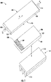
FIG. 1 illustrates an exploded view of an PCM heat sink, according to an embodiment of the present disclosure; -
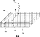
FIG. 2 illustrates an isometric view of a carbon graphite matrix, in accordance with an embodiment of the present disclosure; and -
FIG. 3 illustrates a flow chart of a method of manufacturing the PCM heat sink, in accordance with an embodiment of the present disclosure. - A detailed description of one or more embodiments of the disclosed apparatus and method are presented herein by way of exemplification and not limitation with reference to the Figures.
- Referring now to
FIG. 1 , an exploded view of anPCM heat sink 100 is illustrated, according to an embodiment of the present disclosure. It is understood that thePCM heat sink 100 illustrated inFIG. 1 is an example configuration and the embodiments disclosed herein may be applicable to PCM heat sinks having different configurations. In an embodiment, PCM heat sink may use conduction to receive thermal energy directly from a source, such as, for example, an electronics enclosure. ThePCM heat sink 100 includes a sealedchamber 106. This sealedchamber 106 includes acarbon graphite matrix 109 located within the sealedchamber 106 and aPCM 120 such as water or wax sealed within theseal chamber 106. The sealedchamber 106 includes a top 107 and abottom 108. InFIG. 1 , the sealedchamber 106 is illustrated such that the PCM 120 is visible. However, it shall be understood that in practice, thetop 107 is formed of solid material and that thePCM 120 may not be visible. - The
PCM heat sink 100 also includes afluid passage element 101. A heat transmission fluid enters (e.g., Freon or water, for example) anend 103 of thefluid passage element 101 via inlet passage (e.g., pipe) 102 and exits it viaoutlet passage 114. The fluid generally traverses thefluid passage element 101 in the direction shown by arrow A. Thefluid passage element 101 illustrated inFIG. 1 includes aconnector portion 104 arranged between theends 103 through which the fluid passes while traversing from theinlet passage 102 to theoutlet passage 114. Theconnector portion 104 in particular, and thefluid passage element 101 generally, includes abottom 105. When thePCM heat sink 100 is assembled, thetop 107 of the sealedchamber 106 is in thermal contact with thebottom 105 of thefluid passage element 101. - The
PCM heat sink 100 also optionally include aheat release element 111. As illustrated, theheat release element 111 includesheat diffusion fins 113 and atop 112. In some cases, theheat release element 111 can be brought into thermal contact with the sealedchamber 106 to dissipate heat stored therein. For example, in the context of a satellite, heat may be stored in the sealedchamber 106 until the satellite is not in line-of-sight with the sun. At that time, thebottom 108 of the sealedchamber 106 can be brought into contact with thetop 112 of theheat release element 111 and the heat can be released viafins 113 into space. - The PCM 120 is located within the sealed
chamber 105 and is embedded within thecarbon graphite matrix 109. In an embodiment thePCM 120 may be wax or paraffin wax. Thecarbon graphite matrix 109 is configured to shape-stabilize thePCM 120 and also increase the thermal conductivity of thePCM 120. Thecarbon graphite matrix 109 conducts heat better than thePCM 120 and may distribute heat better through thePCM 120 than just using PCM 120 alone without acarbon graphite matrix 109. - The
carbon graphite matrix 109 is composed of a graphite material forming a monolithic matrix structure, however few options of this material are available, with one of the best having 60% open porosity. It is desirable to increase the percentage of open porosity, which allows formore PCM 120 to be loaded into sealedchamber 106, without compromising the matrices' ability to shape stabilize thePCM 120 during phase transition cycles. The embodiments disclosed herein seek to remove some of thecarbon graphite matrix 109 and replace some of thecarbon graphite matrix 109 with an expanded graphite 150 (seeFIG. 2 ). Advantageously, by replacing some of thecarbon graphite matrix 109 with expanded graphite 150 (seeFIG. 2 ), the volume ofPCM 120 can be increased within the sealedchamber 106, providing for higher amounts of latent heat storage. - Referring not to
FIG. 2 , with continued reference toFIG. 1 , acarbon graphite matrix 109 is illustrated in accordance with an embodiment of the present disclosure. Thecarbon graphite matrix 109 may be a monolithic matrix structure composed of a single material. Thecarbon graphite matrix 109 may have a porosity between 95% and 50%. For example, porosity of 95% would mean that thecarbon graphite matrix 109 is 5% of the volume, with 95% of the volume being open space. Thecarbon graphite matrix 109 ofFIG. 2 includes removedportions 121 where a portion of thecarbon graphite matrix 109 has been removed. The portion of thecarbon graphite matrix 109 may have been removed via drilling, machining, or any other manufacturing process. In an embodiment, the removedportion 121 may be ahole 121a. Thehole 121a may extend completely through or partially through thecarbon graphite matrix 109. In another embodiment, the removedportion 121 may be a channel 121b. The channel 121b may extend completely through or partially through thecarbon graphite matrix 109. In an embodiment, there may any number of removedportions 121. The removedportions 121 may also be located on anyside 110 of thecarbon graphite matrix 109. The removedportions 121 are then back filled to a selected percentage with an expandedgraphite 150. The selected percentage is a percentage of the removedportions 121 and may be measured between 0% - 100%. At 0% none of the removedportions 121 are filled with any expandedgraphite 150 and at 100% all of the removedportions 121 are completely filled with the expandedgraphite 150. ThePCM 120 is located within the sealedchamber 105 and is embedded within thecarbon graphite matrix 109 and the expandedgraphite 150. The expandedgraphite 150 may have a porosity between 2% and 20%. In an embodiment, the expanded graphite has a porosity of 10%. - The
carbon graphite matrix 109 has an effective conductivity higher than an effective conductivity of the expandedgraphite 150. As thecarbon graphite matrix 109 is removed and replaced with expandedgraphite 150 the effective conductivity of the combination of thecarbon graphite matrix 109 and the expandedgraphite 150 will decrease but the addition of the expanded graphite will allow the volume available for thePCM 120 to increase, thus giving thePCM 120 more thermal capacity. Thus, using allcarbon graphite matrix 109 results in high effective conductivity but low available volume for thePCM 120, whereas using all expandedgraphite 150 results in low effective conductivity but more available volume for thePCM 120. - Therefore, the removed
portions 121 ofFIG. 2 should remove some but not all of thecarbon graphite matrix 109 and replace it with a selected percentage expandedgraphite 150 to increase the available volume for thePCM 120 while maintaining a high effective conductivity. In an embodiment, the selected percentage of expandedgraphite 150 may be between about 0 and 10% of the removedportion 121. In another embodiment, the selected percentage of expandedgraphite 150 may be between about 5% and 10% of the removedportion 121. In an embodiment, the selected percentage of expandedgraphite 150 may be about 10% of the removedportion 121. - Referring now to
FIG. 3 , with continued reference toFIGS. 1-2 , a flow chart ofmethod 400 of manufacturing aPCM heat sink 100 is illustrated, in accordance with an embodiment of the disclosure. - At
block 404, acarbon graphite matrix 109 having one or moreremoved portions 121 is obtained. Atblock 406, an expandedgraphite 150 is inserted into the one or moreremoved portions 121. The expandedgraphite 150 may fill a selected percentage of the one or moreremoved portions 121. The selected percentage may be less than or equal to 10 percent. The selected percentage may be equal to 10 percent. - The
method 400 may further include forming thecarbon graphite matrix 109 having one or moreremoved portions 121 In another embodiment, thecarbon graphite matrix 109 and the one or moreremoved portions 121 may be formed by machining one ormore holes 121a in thecarbon graphite matrix 109 to form the one or moreremoved portions 121. In another embodiment, thecarbon graphite matrix 109 and the one or moreremoved portions 121 may be formed by machining one or more channels 121b in thecarbon graphite matrix 109 to form the one or moreremoved portions 121. - The
method 400 may also include inserting thecarbon graphite matrix 109 and the expandedgraphite 150 into a sealedchamber 106. Themethod 400 may also include inserting aPCM 120 into thecarbon graphite matrix 109 and the expandedgraphite 150 that are located within the sealedchamber 106. - The
PCM 120 may be inserted into thecarbon graphite matrix 109 simultaneously with the expandedgraphite 150. For example, thePCM 120 may be inserted into thecarbon graphite matrix 109 simultaneously with the expandedgraphite 150 via a vacuum. ThePCM 120 may be mixed into a slurry with the expandedgraphite 150 to be inserted into thecarbon graphite matrix 109 simultaneously. - Alternatively, the expanded
graphite 150 may be inserted into thecarbon graphite matrix 109 prior to thePCM 120. For example, the expandedgraphite 150 may be mixed into thecarbon graphite matrix 109 and then thePCM 120 may be inserted into thecarbon graphite matrix 109 and the expandedgraphite 150 via a vacuum. - While the above description has described the flow process of
FIG. 3 in a particular order, it should be appreciated that unless otherwise specifically required in the attached claims that the ordering of the steps may be varied and the order of the steps may occur simultaneously or near simultaneously, such as in layers. - Technical effects and benefits of the features described herein include removing a selected portion of a carbon graphite matrix and replacing with expanded
graphite 150 to increase the volume available for PCM and thermal capacity while not compromising too much on conductivity. - A detailed description of one or more embodiments of the disclosed apparatus and method are presented herein by way of exemplification and not limitation with reference to the Figures.
- The term "about" is intended to include the degree of error associated with measurement of the particular quantity based upon the equipment available at the time of filing the application.
- The terminology used herein is for the purpose of describing particular embodiments only and is not intended to be limiting of the present disclosure. As used herein, the singular forms "a", "an" and "the" are intended to include the plural forms as well, unless the context clearly indicates otherwise. It will be further understood that the terms "comprises" and/or "comprising," when used in this specification, specify the presence of stated features, integers, steps, operations, elements, and/or components, but do not preclude the presence or addition of one or more other features, integers, steps, operations, element components, and/or groups thereof.
- While the present disclosure has been described with reference to an exemplary embodiment or embodiments, it will be understood by those skilled in the art that various changes may be made and equivalents may be substituted for elements thereof without departing from the scope of the present disclosure. In addition, many modifications may be made to adapt a particular situation or material to the teachings of the present disclosure without departing from the essential scope thereof. Therefore, it is intended that the present disclosure not be limited to the particular embodiment disclosed as the best mode contemplated for carrying out this present disclosure, but that the present disclosure will include all embodiments falling within the scope of the claims.
Claims (15)
- A phase change material heat sink (100) comprising:a carbon graphite matrix (109) having one or more removed portions; andan expanded graphite (150) located within the one or more removed portions.
- The phase change material heat sink of claim 1, further comprising:
a sealed chamber, wherein the carbon graphite matrix (109) is located within the sealed chamber. - The phase change material heat sink of claim 2, further comprising:
a phase change material located within the sealed chamber, wherein the phase change material embedded within the carbon graphite matrix (109) and the expanded graphite (150). - The phase change material heat sink of any preceding claim, wherein the one or more removed portions are holes, or wherein the one or more removed portions are channels.
- The phase change material heat sink of any preceding claim, wherein the expanded graphite (150) fills a selected percentage of the one or more removed portions.
- The phase change material heat sink of claim 5, wherein the selected percentage is less than or equal to 10 percent, or wherein the selected percentage is equal to 10 percent.7.
- A method of manufacturing a phase change material heat sink, the method comprising:obtaining a carbon graphite matrix (109) having one or more removed portions; andinserting an expanded graphite (150) into the one or more removed portions.
- The method of claim 7, further comprising:
forming the carbon graphite matrix (109) having the one or more removed portions. - The method of claim 7 or 8, further comprising:
machining one or more holes in the carbon graphite matrix (109) to form the one or more removed portions. - The method of any of claims 7 to 9, further comprising:
machining one or more channels in the carbon graphite matrix (109) to form the one or more removed portions. - The method of any of claims 7 to 10, further comprising:
inserting the carbon graphite matrix (109) and the expanded graphite (150) into a sealed chamber, and optionally further comprising:
inserting a phase change material into the carbon graphite matrix (109) and the expanded graphite (150) located within the sealed chamber. - The method of any of claims 7 to 11, wherein the expanded graphite (150) fills a selected percentage of the one or more removed portions, and optionally
wherein the selected percentage is less than or equal to 10 percent, or wherein the selected percentage is equal to 10 percent. - The method of claim 13, further comprising:
inserting a phase change material into the carbon graphite matrix (109) simultaneously with the expanded graphite (150). - The method of claim 11, further comprising:
inserting a phase change material into the carbon graphite matrix (109) simultaneously with the expanded graphite (150) via a vacuum. - The method of claim 11, further comprising:
inserting a phase change material into the carbon graphite matrix (109) and the expanded graphite (150) via a vacuum.
Applications Claiming Priority (1)
| Application Number | Priority Date | Filing Date | Title |
|---|---|---|---|
| US17/328,449 US20220373267A1 (en) | 2021-05-24 | 2021-05-24 | Lightweight carbon foam structure for phase change material heat sinks |
Publications (2)
| Publication Number | Publication Date |
|---|---|
| EP4095474A1 true EP4095474A1 (en) | 2022-11-30 |
| EP4095474B1 EP4095474B1 (en) | 2024-04-03 |
Family
ID=81846279
Family Applications (1)
| Application Number | Title | Priority Date | Filing Date |
|---|---|---|---|
| EP22175077.1A Active EP4095474B1 (en) | 2021-05-24 | 2022-05-24 | Lightweight carbon foam structure for phase change material heat sinks |
Country Status (3)
| Country | Link |
|---|---|
| US (2) | US20220373267A1 (en) |
| EP (1) | EP4095474B1 (en) |
| CN (1) | CN115397189A (en) |
Families Citing this family (1)
| Publication number | Priority date | Publication date | Assignee | Title |
|---|---|---|---|---|
| US20220373267A1 (en) | 2021-05-24 | 2022-11-24 | Hamilton Sundstrand Corporation | Lightweight carbon foam structure for phase change material heat sinks |
Citations (4)
| Publication number | Priority date | Publication date | Assignee | Title |
|---|---|---|---|---|
| US20120240919A1 (en) * | 2007-06-22 | 2012-09-27 | Sgl Carbon Se | Latent heat storage material with phase change material impregnated in a graphite matrix, and production method |
| EP2543950A2 (en) * | 2011-07-08 | 2013-01-09 | Hamilton Sundstrand Space Systems International, Inc. | Phase change material heat sink |
| WO2020197982A1 (en) * | 2019-03-22 | 2020-10-01 | Razack Siddique Khateeb | Thermal management system and device |
| US20200339423A1 (en) * | 2019-04-29 | 2020-10-29 | Nanotek Instruments, Inc. | Oriented graphene sheet-enhanced vapor-based heat transfer device and process for producing same |
Family Cites Families (19)
| Publication number | Priority date | Publication date | Assignee | Title |
|---|---|---|---|---|
| JPH06279752A (en) * | 1993-03-26 | 1994-10-04 | Nippon Pillar Packing Co Ltd | Packing material |
| DE19630073B4 (en) * | 1996-07-25 | 2004-04-01 | Sgl Carbon Ag | Device for storing heat or cold in a storage system made of pressed graphite expandate and a solid-liquid phase change material and method for its production |
| US6037032A (en) | 1997-09-02 | 2000-03-14 | Lockheed Martin Energy Research Corp. | Pitch-based carbon foam heat sink with phase change material |
| US6033506A (en) * | 1997-09-02 | 2000-03-07 | Lockheed Martin Engery Research Corporation | Process for making carbon foam |
| US6503626B1 (en) * | 2000-02-25 | 2003-01-07 | Graftech Inc. | Graphite-based heat sink |
| DE10157671A1 (en) * | 2001-11-24 | 2003-06-05 | Merck Patent Gmbh | Optimized use of PCM in cooling devices |
| US7316262B1 (en) * | 2004-01-26 | 2008-01-08 | Rini Technologies, Inc. | Method and apparatus for absorbing thermal energy |
| US8171984B2 (en) * | 2006-02-01 | 2012-05-08 | Sgl Carbon Ag | Latent heat storage devices |
| US7969075B2 (en) * | 2009-02-10 | 2011-06-28 | Lumenetix, Inc. | Thermal storage system using encapsulated phase change materials in LED lamps |
| CN102088819B (en) * | 2009-12-07 | 2012-09-05 | 耿世达 | Novel electronic circuit substrate and manufacturing process thereof |
| US20130264023A1 (en) * | 2012-04-09 | 2013-10-10 | Sgl Carbon Se | Latent heat storage device with phase change material and graphite matrix |
| US20160209124A1 (en) * | 2013-08-29 | 2016-07-21 | Board Of Regents, The University Of Texas System | Thermal storage units, components thereof, and methods of making and using them |
| FR3024214A3 (en) * | 2014-07-23 | 2016-01-29 | Muller & Cie Soc | SEASONAL THERMOELECTRIC STORAGE APPARATUS |
| DE102015212132A1 (en) * | 2015-06-30 | 2017-01-05 | Sgl Carbon Se | Use of a composite material for thermal management |
| KR102584293B1 (en) * | 2015-12-28 | 2023-10-05 | 나노텍 인스트러먼츠, 인코포레이티드 | Graphene-carbon hybrid foam |
| CN107227807A (en) * | 2017-06-13 | 2017-10-03 | 华南理工大学 | A kind of phase-change accumulation energy building heat preservation structure |
| CN108079934B (en) * | 2017-11-30 | 2019-02-22 | 山东大学 | A kind of composite material and preparation method thereof |
| US11289697B2 (en) * | 2018-11-26 | 2022-03-29 | Global Graphene Group, Inc. | Graphite protected anode active material particles for lithium batteries |
| US20220373267A1 (en) | 2021-05-24 | 2022-11-24 | Hamilton Sundstrand Corporation | Lightweight carbon foam structure for phase change material heat sinks |
-
2021
- 2021-05-24 US US17/328,449 patent/US20220373267A1/en not_active Abandoned
-
2022
- 2022-04-19 CN CN202210411339.5A patent/CN115397189A/en active Pending
- 2022-05-24 EP EP22175077.1A patent/EP4095474B1/en active Active
-
2023
- 2023-04-28 US US18/308,923 patent/US12181225B2/en active Active
Patent Citations (4)
| Publication number | Priority date | Publication date | Assignee | Title |
|---|---|---|---|---|
| US20120240919A1 (en) * | 2007-06-22 | 2012-09-27 | Sgl Carbon Se | Latent heat storage material with phase change material impregnated in a graphite matrix, and production method |
| EP2543950A2 (en) * | 2011-07-08 | 2013-01-09 | Hamilton Sundstrand Space Systems International, Inc. | Phase change material heat sink |
| WO2020197982A1 (en) * | 2019-03-22 | 2020-10-01 | Razack Siddique Khateeb | Thermal management system and device |
| US20200339423A1 (en) * | 2019-04-29 | 2020-10-29 | Nanotek Instruments, Inc. | Oriented graphene sheet-enhanced vapor-based heat transfer device and process for producing same |
Also Published As
| Publication number | Publication date |
|---|---|
| US12181225B2 (en) | 2024-12-31 |
| US20230266073A1 (en) | 2023-08-24 |
| US20220373267A1 (en) | 2022-11-24 |
| EP4095474B1 (en) | 2024-04-03 |
| CN115397189A (en) | 2022-11-25 |
| JP2022180306A (en) | 2022-12-06 |
Similar Documents
| Publication | Publication Date | Title |
|---|---|---|
| US12181225B2 (en) | Lightweight carbon foam structure for phase change material heat sinks | |
| US11764422B2 (en) | Thermal management of energy storage devices via oscillating heat pipes | |
| EP3353485B1 (en) | Method of cooling a component with a heat exchanger | |
| US20030141045A1 (en) | Heat pipe and method of manufacturing the same | |
| CN107110613B (en) | Heat storage container and heat storage device including heat storage container | |
| US8033017B2 (en) | Method for manufacturing evaporator for loop heat pipe system | |
| JP3883965B2 (en) | Heat exchanger | |
| KR20120104182A (en) | Tank for storing and withdrawing hydrogen and/or heat | |
| TW201007112A (en) | Heat transfer assembly and methods thereof | |
| CA2940035A1 (en) | Thermal management system | |
| KR102166569B1 (en) | Structure of heat storage heat exchanger using phase change material | |
| CN103033078A (en) | Loop heat pipe and electronic apparatus | |
| US7882888B1 (en) | Two-phase heat transfer system including a thermal capacitance device | |
| US12368196B2 (en) | Phase-change cooling module and battery pack using same | |
| CN107076522A (en) | Refrigerant intermediate device, cooling device including refrigerant intermediate device, and cooling method | |
| CA2837151A1 (en) | Method for manufacturing a metal foam provided with channels and resulting metal foam | |
| WO2020197982A1 (en) | Thermal management system and device | |
| GB2585892A (en) | Hydrogen Storage Device | |
| US20070295496A1 (en) | Diamond Composite Heat Spreader | |
| US4221259A (en) | Process for storing calories | |
| JP7862918B2 (en) | Lightweight carbon foam structure for phase change material heat sinks | |
| WO2010121365A1 (en) | Heat transfer device having metallic open cell porous wicking structure | |
| US10837712B1 (en) | Multi-bore constant conductance heat pipe for high heat flux and thermal storage | |
| TW201007110A (en) | Method of manufacturing evaporator for loop heat pipe system | |
| Wierschke et al. | Heat dissipation with pitch-based carbon foams and phase-change materials |
Legal Events
| Date | Code | Title | Description |
|---|---|---|---|
| PUAI | Public reference made under article 153(3) epc to a published international application that has entered the european phase |
Free format text: ORIGINAL CODE: 0009012 |
|
| STAA | Information on the status of an ep patent application or granted ep patent |
Free format text: STATUS: THE APPLICATION HAS BEEN PUBLISHED |
|
| AK | Designated contracting states |
Kind code of ref document: A1 Designated state(s): AL AT BE BG CH CY CZ DE DK EE ES FI FR GB GR HR HU IE IS IT LI LT LU LV MC MK MT NL NO PL PT RO RS SE SI SK SM TR |
|
| STAA | Information on the status of an ep patent application or granted ep patent |
Free format text: STATUS: REQUEST FOR EXAMINATION WAS MADE |
|
| 17P | Request for examination filed |
Effective date: 20230530 |
|
| RBV | Designated contracting states (corrected) |
Designated state(s): AL AT BE BG CH CY CZ DE DK EE ES FI FR GB GR HR HU IE IS IT LI LT LU LV MC MK MT NL NO PL PT RO RS SE SI SK SM TR |
|
| GRAP | Despatch of communication of intention to grant a patent |
Free format text: ORIGINAL CODE: EPIDOSNIGR1 |
|
| STAA | Information on the status of an ep patent application or granted ep patent |
Free format text: STATUS: GRANT OF PATENT IS INTENDED |
|
| INTG | Intention to grant announced |
Effective date: 20231215 |
|
| GRAS | Grant fee paid |
Free format text: ORIGINAL CODE: EPIDOSNIGR3 |
|
| GRAA | (expected) grant |
Free format text: ORIGINAL CODE: 0009210 |
|
| STAA | Information on the status of an ep patent application or granted ep patent |
Free format text: STATUS: THE PATENT HAS BEEN GRANTED |
|
| AK | Designated contracting states |
Kind code of ref document: B1 Designated state(s): AL AT BE BG CH CY CZ DE DK EE ES FI FR GB GR HR HU IE IS IT LI LT LU LV MC MK MT NL NO PL PT RO RS SE SI SK SM TR |
|
| REG | Reference to a national code |
Ref country code: CH Ref legal event code: EP |
|
| REG | Reference to a national code |
Ref country code: DE Ref legal event code: R096 Ref document number: 602022002646 Country of ref document: DE |
|
| REG | Reference to a national code |
Ref country code: IE Ref legal event code: FG4D |
|
| REG | Reference to a national code |
Ref country code: LT Ref legal event code: MG9D |
|
| REG | Reference to a national code |
Ref country code: NL Ref legal event code: MP Effective date: 20240403 |
|
| REG | Reference to a national code |
Ref country code: AT Ref legal event code: MK05 Ref document number: 1672764 Country of ref document: AT Kind code of ref document: T Effective date: 20240403 |
|
| PG25 | Lapsed in a contracting state [announced via postgrant information from national office to epo] |
Ref country code: NL Free format text: LAPSE BECAUSE OF FAILURE TO SUBMIT A TRANSLATION OF THE DESCRIPTION OR TO PAY THE FEE WITHIN THE PRESCRIBED TIME-LIMIT Effective date: 20240403 |
|
| PG25 | Lapsed in a contracting state [announced via postgrant information from national office to epo] |
Ref country code: NL Free format text: LAPSE BECAUSE OF FAILURE TO SUBMIT A TRANSLATION OF THE DESCRIPTION OR TO PAY THE FEE WITHIN THE PRESCRIBED TIME-LIMIT Effective date: 20240403 |
|
| PG25 | Lapsed in a contracting state [announced via postgrant information from national office to epo] |
Ref country code: IS Free format text: LAPSE BECAUSE OF FAILURE TO SUBMIT A TRANSLATION OF THE DESCRIPTION OR TO PAY THE FEE WITHIN THE PRESCRIBED TIME-LIMIT Effective date: 20240803 |
|
| PG25 | Lapsed in a contracting state [announced via postgrant information from national office to epo] |
Ref country code: BG Free format text: LAPSE BECAUSE OF FAILURE TO SUBMIT A TRANSLATION OF THE DESCRIPTION OR TO PAY THE FEE WITHIN THE PRESCRIBED TIME-LIMIT Effective date: 20240403 |
|
| PG25 | Lapsed in a contracting state [announced via postgrant information from national office to epo] |
Ref country code: HR Free format text: LAPSE BECAUSE OF FAILURE TO SUBMIT A TRANSLATION OF THE DESCRIPTION OR TO PAY THE FEE WITHIN THE PRESCRIBED TIME-LIMIT Effective date: 20240403 Ref country code: FI Free format text: LAPSE BECAUSE OF FAILURE TO SUBMIT A TRANSLATION OF THE DESCRIPTION OR TO PAY THE FEE WITHIN THE PRESCRIBED TIME-LIMIT Effective date: 20240403 |
|
| PG25 | Lapsed in a contracting state [announced via postgrant information from national office to epo] |
Ref country code: GR Free format text: LAPSE BECAUSE OF FAILURE TO SUBMIT A TRANSLATION OF THE DESCRIPTION OR TO PAY THE FEE WITHIN THE PRESCRIBED TIME-LIMIT Effective date: 20240704 |
|
| PG25 | Lapsed in a contracting state [announced via postgrant information from national office to epo] |
Ref country code: PT Free format text: LAPSE BECAUSE OF FAILURE TO SUBMIT A TRANSLATION OF THE DESCRIPTION OR TO PAY THE FEE WITHIN THE PRESCRIBED TIME-LIMIT Effective date: 20240805 |
|
| PG25 | Lapsed in a contracting state [announced via postgrant information from national office to epo] |
Ref country code: ES Free format text: LAPSE BECAUSE OF FAILURE TO SUBMIT A TRANSLATION OF THE DESCRIPTION OR TO PAY THE FEE WITHIN THE PRESCRIBED TIME-LIMIT Effective date: 20240403 |
|
| PG25 | Lapsed in a contracting state [announced via postgrant information from national office to epo] |
Ref country code: CZ Free format text: LAPSE BECAUSE OF FAILURE TO SUBMIT A TRANSLATION OF THE DESCRIPTION OR TO PAY THE FEE WITHIN THE PRESCRIBED TIME-LIMIT Effective date: 20240403 |
|
| PG25 | Lapsed in a contracting state [announced via postgrant information from national office to epo] |
Ref country code: AT Free format text: LAPSE BECAUSE OF FAILURE TO SUBMIT A TRANSLATION OF THE DESCRIPTION OR TO PAY THE FEE WITHIN THE PRESCRIBED TIME-LIMIT Effective date: 20240403 |
|
| PG25 | Lapsed in a contracting state [announced via postgrant information from national office to epo] |
Ref country code: PL Free format text: LAPSE BECAUSE OF FAILURE TO SUBMIT A TRANSLATION OF THE DESCRIPTION OR TO PAY THE FEE WITHIN THE PRESCRIBED TIME-LIMIT Effective date: 20240403 |
|
| PG25 | Lapsed in a contracting state [announced via postgrant information from national office to epo] |
Ref country code: LV Free format text: LAPSE BECAUSE OF FAILURE TO SUBMIT A TRANSLATION OF THE DESCRIPTION OR TO PAY THE FEE WITHIN THE PRESCRIBED TIME-LIMIT Effective date: 20240403 |
|
| PG25 | Lapsed in a contracting state [announced via postgrant information from national office to epo] |
Ref country code: PT Free format text: LAPSE BECAUSE OF FAILURE TO SUBMIT A TRANSLATION OF THE DESCRIPTION OR TO PAY THE FEE WITHIN THE PRESCRIBED TIME-LIMIT Effective date: 20240805 Ref country code: PL Free format text: LAPSE BECAUSE OF FAILURE TO SUBMIT A TRANSLATION OF THE DESCRIPTION OR TO PAY THE FEE WITHIN THE PRESCRIBED TIME-LIMIT Effective date: 20240403 Ref country code: NO Free format text: LAPSE BECAUSE OF FAILURE TO SUBMIT A TRANSLATION OF THE DESCRIPTION OR TO PAY THE FEE WITHIN THE PRESCRIBED TIME-LIMIT Effective date: 20240703 Ref country code: LV Free format text: LAPSE BECAUSE OF FAILURE TO SUBMIT A TRANSLATION OF THE DESCRIPTION OR TO PAY THE FEE WITHIN THE PRESCRIBED TIME-LIMIT Effective date: 20240403 Ref country code: IS Free format text: LAPSE BECAUSE OF FAILURE TO SUBMIT A TRANSLATION OF THE DESCRIPTION OR TO PAY THE FEE WITHIN THE PRESCRIBED TIME-LIMIT Effective date: 20240803 Ref country code: HR Free format text: LAPSE BECAUSE OF FAILURE TO SUBMIT A TRANSLATION OF THE DESCRIPTION OR TO PAY THE FEE WITHIN THE PRESCRIBED TIME-LIMIT Effective date: 20240403 Ref country code: GR Free format text: LAPSE BECAUSE OF FAILURE TO SUBMIT A TRANSLATION OF THE DESCRIPTION OR TO PAY THE FEE WITHIN THE PRESCRIBED TIME-LIMIT Effective date: 20240704 Ref country code: FI Free format text: LAPSE BECAUSE OF FAILURE TO SUBMIT A TRANSLATION OF THE DESCRIPTION OR TO PAY THE FEE WITHIN THE PRESCRIBED TIME-LIMIT Effective date: 20240403 Ref country code: ES Free format text: LAPSE BECAUSE OF FAILURE TO SUBMIT A TRANSLATION OF THE DESCRIPTION OR TO PAY THE FEE WITHIN THE PRESCRIBED TIME-LIMIT Effective date: 20240403 Ref country code: CZ Free format text: LAPSE BECAUSE OF FAILURE TO SUBMIT A TRANSLATION OF THE DESCRIPTION OR TO PAY THE FEE WITHIN THE PRESCRIBED TIME-LIMIT Effective date: 20240403 Ref country code: BG Free format text: LAPSE BECAUSE OF FAILURE TO SUBMIT A TRANSLATION OF THE DESCRIPTION OR TO PAY THE FEE WITHIN THE PRESCRIBED TIME-LIMIT Effective date: 20240403 Ref country code: AT Free format text: LAPSE BECAUSE OF FAILURE TO SUBMIT A TRANSLATION OF THE DESCRIPTION OR TO PAY THE FEE WITHIN THE PRESCRIBED TIME-LIMIT Effective date: 20240403 Ref country code: RS Free format text: LAPSE BECAUSE OF FAILURE TO SUBMIT A TRANSLATION OF THE DESCRIPTION OR TO PAY THE FEE WITHIN THE PRESCRIBED TIME-LIMIT Effective date: 20240703 |
|
| REG | Reference to a national code |
Ref country code: DE Ref legal event code: R097 Ref document number: 602022002646 Country of ref document: DE |
|
| PG25 | Lapsed in a contracting state [announced via postgrant information from national office to epo] |
Ref country code: DK Free format text: LAPSE BECAUSE OF FAILURE TO SUBMIT A TRANSLATION OF THE DESCRIPTION OR TO PAY THE FEE WITHIN THE PRESCRIBED TIME-LIMIT Effective date: 20240403 |
|
| PG25 | Lapsed in a contracting state [announced via postgrant information from national office to epo] |
Ref country code: LU Free format text: LAPSE BECAUSE OF NON-PAYMENT OF DUE FEES Effective date: 20240524 |
|
| PG25 | Lapsed in a contracting state [announced via postgrant information from national office to epo] |
Ref country code: EE Free format text: LAPSE BECAUSE OF FAILURE TO SUBMIT A TRANSLATION OF THE DESCRIPTION OR TO PAY THE FEE WITHIN THE PRESCRIBED TIME-LIMIT Effective date: 20240403 |
|
| PG25 | Lapsed in a contracting state [announced via postgrant information from national office to epo] |
Ref country code: RO Free format text: LAPSE BECAUSE OF FAILURE TO SUBMIT A TRANSLATION OF THE DESCRIPTION OR TO PAY THE FEE WITHIN THE PRESCRIBED TIME-LIMIT Effective date: 20240403 Ref country code: SK Free format text: LAPSE BECAUSE OF FAILURE TO SUBMIT A TRANSLATION OF THE DESCRIPTION OR TO PAY THE FEE WITHIN THE PRESCRIBED TIME-LIMIT Effective date: 20240403 |
|
| PG25 | Lapsed in a contracting state [announced via postgrant information from national office to epo] |
Ref country code: SM Free format text: LAPSE BECAUSE OF FAILURE TO SUBMIT A TRANSLATION OF THE DESCRIPTION OR TO PAY THE FEE WITHIN THE PRESCRIBED TIME-LIMIT Effective date: 20240403 |
|
| PG25 | Lapsed in a contracting state [announced via postgrant information from national office to epo] |
Ref country code: SM Free format text: LAPSE BECAUSE OF FAILURE TO SUBMIT A TRANSLATION OF THE DESCRIPTION OR TO PAY THE FEE WITHIN THE PRESCRIBED TIME-LIMIT Effective date: 20240403 Ref country code: SK Free format text: LAPSE BECAUSE OF FAILURE TO SUBMIT A TRANSLATION OF THE DESCRIPTION OR TO PAY THE FEE WITHIN THE PRESCRIBED TIME-LIMIT Effective date: 20240403 Ref country code: RO Free format text: LAPSE BECAUSE OF FAILURE TO SUBMIT A TRANSLATION OF THE DESCRIPTION OR TO PAY THE FEE WITHIN THE PRESCRIBED TIME-LIMIT Effective date: 20240403 Ref country code: LU Free format text: LAPSE BECAUSE OF NON-PAYMENT OF DUE FEES Effective date: 20240524 Ref country code: EE Free format text: LAPSE BECAUSE OF FAILURE TO SUBMIT A TRANSLATION OF THE DESCRIPTION OR TO PAY THE FEE WITHIN THE PRESCRIBED TIME-LIMIT Effective date: 20240403 Ref country code: DK Free format text: LAPSE BECAUSE OF FAILURE TO SUBMIT A TRANSLATION OF THE DESCRIPTION OR TO PAY THE FEE WITHIN THE PRESCRIBED TIME-LIMIT Effective date: 20240403 Ref country code: MC Free format text: LAPSE BECAUSE OF FAILURE TO SUBMIT A TRANSLATION OF THE DESCRIPTION OR TO PAY THE FEE WITHIN THE PRESCRIBED TIME-LIMIT Effective date: 20240403 |
|
| PLBE | No opposition filed within time limit |
Free format text: ORIGINAL CODE: 0009261 |
|
| STAA | Information on the status of an ep patent application or granted ep patent |
Free format text: STATUS: NO OPPOSITION FILED WITHIN TIME LIMIT |
|
| REG | Reference to a national code |
Ref country code: BE Ref legal event code: MM Effective date: 20240531 |
|
| 26N | No opposition filed |
Effective date: 20250106 |
|
| PG25 | Lapsed in a contracting state [announced via postgrant information from national office to epo] |
Ref country code: IE Free format text: LAPSE BECAUSE OF NON-PAYMENT OF DUE FEES Effective date: 20240524 |
|
| PG25 | Lapsed in a contracting state [announced via postgrant information from national office to epo] |
Ref country code: SI Free format text: LAPSE BECAUSE OF FAILURE TO SUBMIT A TRANSLATION OF THE DESCRIPTION OR TO PAY THE FEE WITHIN THE PRESCRIBED TIME-LIMIT Effective date: 20240403 Ref country code: BE Free format text: LAPSE BECAUSE OF NON-PAYMENT OF DUE FEES Effective date: 20240531 |
|
| PGFP | Annual fee paid to national office [announced via postgrant information from national office to epo] |
Ref country code: DE Payment date: 20250423 Year of fee payment: 4 |
|
| PGFP | Annual fee paid to national office [announced via postgrant information from national office to epo] |
Ref country code: FR Payment date: 20250423 Year of fee payment: 4 |
|
| PG25 | Lapsed in a contracting state [announced via postgrant information from national office to epo] |
Ref country code: CY Free format text: LAPSE BECAUSE OF FAILURE TO SUBMIT A TRANSLATION OF THE DESCRIPTION OR TO PAY THE FEE WITHIN THE PRESCRIBED TIME-LIMIT; INVALID AB INITIO Effective date: 20220524 |
|
| PG25 | Lapsed in a contracting state [announced via postgrant information from national office to epo] |
Ref country code: HU Free format text: LAPSE BECAUSE OF FAILURE TO SUBMIT A TRANSLATION OF THE DESCRIPTION OR TO PAY THE FEE WITHIN THE PRESCRIBED TIME-LIMIT; INVALID AB INITIO Effective date: 20220524 |
|
| PG25 | Lapsed in a contracting state [announced via postgrant information from national office to epo] |
Ref country code: SE Free format text: LAPSE BECAUSE OF FAILURE TO SUBMIT A TRANSLATION OF THE DESCRIPTION OR TO PAY THE FEE WITHIN THE PRESCRIBED TIME-LIMIT Effective date: 20240403 |
|
| REG | Reference to a national code |
Ref country code: CH Ref legal event code: H13 Free format text: ST27 STATUS EVENT CODE: U-0-0-H10-H13 (AS PROVIDED BY THE NATIONAL OFFICE) Effective date: 20251223 |
|
| PG25 | Lapsed in a contracting state [announced via postgrant information from national office to epo] |
Ref country code: CH Free format text: LAPSE BECAUSE OF NON-PAYMENT OF DUE FEES Effective date: 20250531 |
|
| PG25 | Lapsed in a contracting state [announced via postgrant information from national office to epo] |
Ref country code: IT Free format text: LAPSE BECAUSE OF FAILURE TO SUBMIT A TRANSLATION OF THE DESCRIPTION OR TO PAY THE FEE WITHIN THE PRESCRIBED TIME-LIMIT Effective date: 20240403 |