EP4095437A1 - Explosion-proof lamp - Google Patents
Explosion-proof lamp Download PDFInfo
- Publication number
- EP4095437A1 EP4095437A1 EP21712894.1A EP21712894A EP4095437A1 EP 4095437 A1 EP4095437 A1 EP 4095437A1 EP 21712894 A EP21712894 A EP 21712894A EP 4095437 A1 EP4095437 A1 EP 4095437A1
- Authority
- EP
- European Patent Office
- Prior art keywords
- cavity
- light source
- explosion
- heat dissipation
- proof lamp
- Prior art date
- Legal status (The legal status is an assumption and is not a legal conclusion. Google has not performed a legal analysis and makes no representation as to the accuracy of the status listed.)
- Pending
Links
Images




Classifications
-
- F—MECHANICAL ENGINEERING; LIGHTING; HEATING; WEAPONS; BLASTING
- F21—LIGHTING
- F21V—FUNCTIONAL FEATURES OR DETAILS OF LIGHTING DEVICES OR SYSTEMS THEREOF; STRUCTURAL COMBINATIONS OF LIGHTING DEVICES WITH OTHER ARTICLES, NOT OTHERWISE PROVIDED FOR
- F21V25/00—Safety devices structurally associated with lighting devices
- F21V25/12—Flameproof or explosion-proof arrangements
-
- F—MECHANICAL ENGINEERING; LIGHTING; HEATING; WEAPONS; BLASTING
- F21—LIGHTING
- F21V—FUNCTIONAL FEATURES OR DETAILS OF LIGHTING DEVICES OR SYSTEMS THEREOF; STRUCTURAL COMBINATIONS OF LIGHTING DEVICES WITH OTHER ARTICLES, NOT OTHERWISE PROVIDED FOR
- F21V23/00—Arrangement of electric circuit elements in or on lighting devices
- F21V23/003—Arrangement of electric circuit elements in or on lighting devices the elements being electronics drivers or controllers for operating the light source, e.g. for a LED array
- F21V23/007—Arrangement of electric circuit elements in or on lighting devices the elements being electronics drivers or controllers for operating the light source, e.g. for a LED array enclosed in a casing
- F21V23/008—Arrangement of electric circuit elements in or on lighting devices the elements being electronics drivers or controllers for operating the light source, e.g. for a LED array enclosed in a casing the casing being outside the housing of the lighting device
-
- F—MECHANICAL ENGINEERING; LIGHTING; HEATING; WEAPONS; BLASTING
- F21—LIGHTING
- F21V—FUNCTIONAL FEATURES OR DETAILS OF LIGHTING DEVICES OR SYSTEMS THEREOF; STRUCTURAL COMBINATIONS OF LIGHTING DEVICES WITH OTHER ARTICLES, NOT OTHERWISE PROVIDED FOR
- F21V29/00—Protecting lighting devices from thermal damage; Cooling or heating arrangements specially adapted for lighting devices or systems
- F21V29/50—Cooling arrangements
- F21V29/70—Cooling arrangements characterised by passive heat-dissipating elements, e.g. heat-sinks
- F21V29/74—Cooling arrangements characterised by passive heat-dissipating elements, e.g. heat-sinks with fins or blades
- F21V29/77—Cooling arrangements characterised by passive heat-dissipating elements, e.g. heat-sinks with fins or blades with essentially identical diverging planar fins or blades, e.g. with fan-like or star-like cross-section
- F21V29/773—Cooling arrangements characterised by passive heat-dissipating elements, e.g. heat-sinks with fins or blades with essentially identical diverging planar fins or blades, e.g. with fan-like or star-like cross-section the planes containing the fins or blades having the direction of the light emitting axis
-
- F—MECHANICAL ENGINEERING; LIGHTING; HEATING; WEAPONS; BLASTING
- F21—LIGHTING
- F21V—FUNCTIONAL FEATURES OR DETAILS OF LIGHTING DEVICES OR SYSTEMS THEREOF; STRUCTURAL COMBINATIONS OF LIGHTING DEVICES WITH OTHER ARTICLES, NOT OTHERWISE PROVIDED FOR
- F21V15/00—Protecting lighting devices from damage
- F21V15/01—Housings, e.g. material or assembling of housing parts
-
- F—MECHANICAL ENGINEERING; LIGHTING; HEATING; WEAPONS; BLASTING
- F21—LIGHTING
- F21V—FUNCTIONAL FEATURES OR DETAILS OF LIGHTING DEVICES OR SYSTEMS THEREOF; STRUCTURAL COMBINATIONS OF LIGHTING DEVICES WITH OTHER ARTICLES, NOT OTHERWISE PROVIDED FOR
- F21V29/00—Protecting lighting devices from thermal damage; Cooling or heating arrangements specially adapted for lighting devices or systems
- F21V29/10—Arrangement of heat-generating components to reduce thermal damage, e.g. by distancing heat-generating components from other components to be protected
-
- F—MECHANICAL ENGINEERING; LIGHTING; HEATING; WEAPONS; BLASTING
- F21—LIGHTING
- F21V—FUNCTIONAL FEATURES OR DETAILS OF LIGHTING DEVICES OR SYSTEMS THEREOF; STRUCTURAL COMBINATIONS OF LIGHTING DEVICES WITH OTHER ARTICLES, NOT OTHERWISE PROVIDED FOR
- F21V31/00—Gas-tight or water-tight arrangements
- F21V31/005—Sealing arrangements therefor
Definitions
- the present utility model relates to the technical field of illumination devices, and in particular to an explosion-proof lamp.
- An explosion-proof lamp is an electrical device applied in the aforementioned extreme environments, and is different from an ordinary lamp in that the explosion-proof lamp needs to meet specific protection requirements.
- LED light sources have high luminous efficiency and high color rendering performance, are small, have a long service life, are gradually taking the place of conventional light sources, and are applied in various lamps.
- Output of a driving power supply required by an explosion-proof LED lamp is a low DC voltage, and can hardly generate sparks. Therefore, explosion-proof LED lamps are safer than other explosion-proof lamps.
- an LED light source is sensitive to temperatures. Heat dissipation is one of key issues that need to be resolved in designing an LED lamp. In order to ensure a service life of an LED lamp, an appropriate heat dissipation method has to be adopted to transfer in a timely manner heat energy generated by the LED lamp. Since an explosion-proof lamp needs to meet protection requirements, a light source and a power supply both need to be mounted in a protective enclosure, thereby increasing difficulty in heat dissipation of an explosion-proof LED lamp.
- the Chinese utility model patent CN 201954378 U provides an integrated flameproofness-based explosion-proof lamp, including at least an electrical box and a lamp portion, and further including a connecting portion.
- the connecting portion is respectively fixedly connected to the electrical box and the lamp portion, so that the electrical box and the lamp portion form an integrated structure.
- This integrated flameproofness-based explosion-proof lamp has the following defects: an integrated flameproof structure causes a cavity wall of the electrical box and the lamp portion to be extremely thick, which increases the weight and costs of the entire lamp, and affects heat dissipation of the entire lamp, thereby affecting a service life of the lamp.
- An objective of the present utility model is to provide an explosion-proof lamp, so as to solve the problem in which an existing explosion-proof lamp has poor heat dissipation performance, and is heavy and expensive.
- the present utility model provides an explosion-proof lamp, comprising a light source cavity and a drive cavity independent of each other, wherein
- the heat dissipation fins of the heat sink are separately distributed in a radial annular form; outer contours of all of the heat dissipation fins of the heat sink form a cylinder.
- the heat dissipation fins of the heat sink are separately distributed in a radial annular form; outer contours of all of the heat dissipation fins of the heat sink form a truncated cone.
- the explosion-proof lamp further comprises an isolation column provided between the heat sink of the light source cavity and the drive cavity and used to control spacing between the light source cavity and the drive cavity.
- the LED light source is mounted on a mounting plate, and the mounting plate is mounted on the heat dissipation bottom plate of the heat sink.
- a cable of the drive cavity sequentially passes through a hole in a drive cavity bottom plate and a hole in the heat dissipation bottom plate, and is connected to the light source in the light source cavity.
- the explosion-proof lamp further comprises an upper cover connected to the drive cavity and used to close the drive cavity and provide a mounting position for the explosion-proof lamp.
- a metal mesh is further provided on an outer side of the glass cover, and surrounds the glass cover from the outer side.
- a seal ring is mounted between the glass cover and the metal mesh. In an embodiment, a seal ring is mounted between the upper cover and the drive cavity; a seal ring is mounted between the glass cover and the heat sink.
- the present utility model provides an explosion-proof lamp; the drive cavity is an increased-safety cavity; the light source cavity is a flameproof cavity; the drive cavity and the light source cavity are independent of each other, thereby facilitating heat dissipation on a surface of a lamp housing and a power driver.
- explosion-proof LED lamps divided according to explosion-proof types include: a flameproof type, an increased-safety type, an intrinsic safety type, a pressurized enclosure type, and the like.
- an explosion-proof LED lamp With respect to an explosion-proof structure, an explosion-proof LED lamp is not different from any other light source of the same explosion-proof type.
- an LED temperature needs to be controlled to reach a temperature group and a temperature range of a corresponding flammable gas or vapor.
- the flameproof type is an explosion-proof type in which measures are taken to allow an internal explosion and prevent a flame from propagating the explosion, and is a most common explosion-proof type.
- the flameproof type uses a flameproof enclosure to prevent an explosion.
- the flameproof enclosure can bear an explosion pressure caused by an internal explosive gas mixture, and prevent an internal explosion from being propagated to an explosive mixture around the enclosure.
- This is a gap-based explosion-proof principle, namely a structure designed on the basis of the principle that a metal gap can prevent propagation of a flame of an explosion and cool an explosion product, thereby extinguishing the flame, lowering a temperature, and suppressing expansion of the explosion.
- An increased-safety electrical device refers to an electrical device having a device structure that, in a normal operating condition, does not generate an electric arc nor a spark and does not have the possibility of igniting an explosive mixture, and further measures are taken to improve the safety of the electrical device to eliminate possibilities of resulting in a dangerous temperature or incurring an electric arc or a spark.
- Explosion-proof lamps provided by the present utility model include three embodiments having different power and/or output lumen values and having slightly different sizes and structures. Detailed description is provided below.
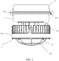
- FIG. 1 and FIG. 2 are respectively a schematic view of an overall structure of an explosion-proof lamp according to a first embodiment of the present utility model and a sectional view of the explosion-proof lamp according to the first embodiment of the present utility model.
- the explosion-proof lamp provided by the present utility model consists of a drive cavity 1 and a light source cavity 2 independent of each other, and the drive cavity 1 and the light source cavity 2 are connected via a conducting wire by means of an insulating sleeve.
- a temperature of a surface of a lamp housing in which the drive cavity 1 and the light source cavity 2 are separated from each other is much lower than a temperature of a surface of a lamp housing in which a drive cavity and a light source housing are integrated.
- the drive cavity 1 is an increased-safety cavity
- the light source cavity 2 is a flameproof cavity.
- FIG. 3 is a top view of the drive cavity according to the first embodiment of the present utility model. As shown in FIG. 3 , a power driver 11 and a junction box 12 are mounted in the drive cavity 1.
- the power driver 11 drives and controls a light source 24 in the light source cavity 2 to be turned on.
- a corresponding power driver 11 is determined and used according to a specific light source configuration.
- the junction box 12 is a wiring terminal, and allows a conducting wire to be easily connected.
- the power driver 11 and the junction box 12 are encapsulated devices, and meet safety requirements on group I electrical devices.
- the power driver 11 and the junction box 12 are encapsulated in an encapsulation material, and therefore do not ignite a surrounding explosive mixture when operating normally and overloaded as approved or faulty as approved.
- the drive cavity 1 meets the national standard "GB 3836.3-2000 Electrical Apparatus for Explosive Gas Atmospheres.”
- the drive cavity 1 further includes an upper cover 13. Respective ends of the upper cover 13 and the drive cavity 1 are connected means of a rotary component 131, and respective other ends are fastened by means of a fastener 132. The fastener 132 is caused to no longer fasten the upper cover 13, and the upper cover 13 is opened by rotating the rotary component 131, so that the interior of the drive cavity 1 is exposed.
- the fastener 132 is a bolt or a screw.
- the rotary component 131 is a hinge.
- the upper cover 13 covers the drive cavity 1, and provides a mounting position for the explosion-proof lamp. Depending on different mounting methods, the upper cover 13 has different shapes and structures.
- IP66 means that a product completely prevents intrusion from foreign bodies, and completely prevents dust from entering therein, and when subjected to severe impact from waves or a water jet, the amount of water entering an electrical device is not sufficient to harm the electrical device.
- the seal ring is an O ring, and is made of rubber.
- the light source cavity 2 consists of a heat sink 21a, a glass cover 22, and a light source 23.
- the heat sink 21a and the glass cover 22 are fixedly connected to form the cavity, and the light source 23 is mounted in the cavity.
- the heat sink 21a includes a heat dissipation bottom plate 211 and a plurality of heat dissipation fins 212, absorbs heat generated in the light source cavity 2, and dissipates the heat into an external environment.
- a through hole is provided in the middle of the heat dissipation bottom plate 211.
- a cable in the drive cavity 1 sequentially passes through a hole in a drive cavity bottom plate and a hole in the heat dissipation bottom plate 211, and is connected to the light source 23 in the light source cavity 2.
- the heat dissipation fins 212 are annularly mounted on the heat dissipation bottom plate 211.
- the heat dissipation fins 212 are separately distributed in a radial annular form, and outer contours of all of the heat dissipation fins 212 form a cylinder.
- the heat dissipation fins 212 and the heat dissipation bottom plate 211 are integrally cast.
- the heat sink 21a is made of aluminum.
- the light source cavity 2 further includes a mounting plate 24.
- the light source 23 is an LED light source, and is mounted on the mounting plate 24, and the mounting plate 24 is further mounted on the heat dissipation bottom plate 211, so that heat generated by the light source 23 is conducted out by the heat dissipation bottom plate 211 and the heat dissipation fins 212.
- the mounting plate 24 is an aluminum base plate. In the light source cavity, the LED light source is mounted on the aluminum base plate, and the aluminum base plate is mounted on the heat dissipation bottom plate of the heat sink.
- FIG. 4a is a schematic view of connecting surfaces of the glass cover and the heat sink according to the first embodiment of the present utility model.
- FIG. 4b is a schematic partial view of the part in the circle shown in FIG. 4a .
- a metal frame 221 is provided on an outer side of the glass cover 22, and binds with the glass cover 22 by means of an adhesive.
- the metal frame 221 is provided with a fixing holder for positioning the glass cover 22.
- the metal frame 221 of the glass cover 22 and the heat dissipation bottom plate 211 of the heat sink 21a are threadingly connected to achieve explosion proofness based on flameproofness.
- a seal ring 25 is provided between the glass cover 22 and the metal frame 221, thereby achieving the IP66 enclosure protection level.
- a seal ring 26 is provided between the metal frame 221 and the heat sink 21a, thereby achieving the IP66 enclosure protection level.
- seal ring 25 and the seal ring 26 are O rings, and are made of rubber.
- FIG. 5a and FIG. 5b are respectively a perspective view and a top view of the glass cover according to the first embodiment of the present utility model.
- a metal mesh 222 is further provided on the outer side of the glass cover 22, and surrounds the glass cover 22 from the outer side.
- the metal mesh 222 is fixed on the metal frame 221, has an explosion-proof function, and prevent glass from cracking due to a severe impact.
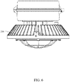
- FIG. 6 and FIG. 7 are respectively a schematic view of an overall structure of an explosion-proof lamp according to a second embodiment of the present utility model and a sectional view of the explosion-proof lamp according to the second embodiment of the present utility model.
- the explosion-proof lamp provided by the present utility model has the same main structure as the first embodiment, and differs from the first embodiment in that the structure of a heat sink 21b is different from that of the heat sink 21A.
- a key to an LED lamp is temperatures, and the temperatures mainly include an LED temperature and a drive temperature.
- the size of a heat sink is designed according to power, so as to ensure that an LED does not fail due to a high temperature.
- heat dissipation fins of the heat sink 21b are separately distributed in a radial annular form, and outer contours of all of the heat dissipation fins form a truncated cone.
- the second embodiment has the same overall structure as the first embodiment, and in the second embodiment, the heat dissipation fins of the heat sink 21b have larger areas and a better heat dissipation effect, so that maximum output power of the explosion-proof lamp of the second embodiment can be greater that of the explosion-proof lamp of the first embodiment.
- the maximum output power of the explosion-proof lamp in the second embodiment is 15 L.
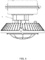
- FIG. 8 and FIG. 9 are respectively a schematic view of an overall structure of an explosion-proof lamp according to a third embodiment of the present utility model and a sectional view of the explosion-proof lamp according to the third embodiment of the present utility model.
- the explosion-proof lamp provided by the present utility model has the same main structure as the second embodiment, and differs from the second embodiment in that the explosion-proof lamp in the third embodiment further includes an isolation column 3.
- the isolation column 3 is provided between the heat sink of the light source cavity 2 and the drive cavity 1, controls spacing between the light source cavity and the drive cavity, and isolates heat between the light source cavity 2 and the drive cavity 1.
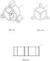
- FIG. 10a to FIG. 10c are respectively a perspective view, a top view, and a front view of the isolation column according to the third embodiment of the present utility model.
- the isolation column 3 is hollow, and a cable in the drive cavity passes through a through hole in the middle, and is connected to the light source in the light source cavity.
- the isolation column 3 is made of aluminum by means of extrusion molding, and can be machined to different heights as required.
- Heat of the light source cavity 2 and the distance between the light source cavity 2 and the drive cavity 1 affect a temperature of the power driver.
- the temperature of the power driver is adjusted by adjusting the distance between the light source cavity 2 and the drive cavity 1, thereby achieving a better heat dissipation than the second embodiment, and allowing greater output power.
- the maximum output power of the explosion-proof lamp in the third embodiment is 25 L, thereby maximumly reducing unit costs and investment of a lamp housing.
- the present utility model provides an explosion-proof lamp; the drive cavity is an increased-safety cavity; the light source cavity is a flameproof cavity; the drive cavity and the light source cavity are independent of each other, thereby facilitating heat dissipation on a surface of a lamp housing and a power driver.
Landscapes
- Engineering & Computer Science (AREA)
- General Engineering & Computer Science (AREA)
- Microelectronics & Electronic Packaging (AREA)
- Arrangement Of Elements, Cooling, Sealing, Or The Like Of Lighting Devices (AREA)
- Non-Portable Lighting Devices Or Systems Thereof (AREA)
Abstract
Description
- The present utility model relates to the technical field of illumination devices, and in particular to an explosion-proof lamp.
- At extreme low/high ambient temperatures, in outdoor or indoor regions where flammable gas, dust, fibers, airborne fluffy matter, or the like exists, in extremely corrosive or humid environments, in hazardous regions for performing machining and manufacturing, and in hazardous fields such as pharmacy, petrochemical, and the like, continuous, stable and efficient illumination lamps are needed.
- An explosion-proof lamp is an electrical device applied in the aforementioned extreme environments, and is different from an ordinary lamp in that the explosion-proof lamp needs to meet specific protection requirements.
- In conventional explosion-proof lamps, metal halide lamps, incandescent lamps, sodium lamps, fluorescent lamps, and the like are used as main light sources, so that power consumption is high, and the lamps and the light sources have high temperatures, are prone to break, produce a large amount of heat, have a short service life, and severely affect production safety. In addition, due to the national energy conservation and emission reduction policies, LED light sources emerge accordingly.
- LED light sources have high luminous efficiency and high color rendering performance, are small, have a long service life, are gradually taking the place of conventional light sources, and are applied in various lamps. Output of a driving power supply required by an explosion-proof LED lamp is a low DC voltage, and can hardly generate sparks. Therefore, explosion-proof LED lamps are safer than other explosion-proof lamps.
- However, an LED light source is sensitive to temperatures. Heat dissipation is one of key issues that need to be resolved in designing an LED lamp. In order to ensure a service life of an LED lamp, an appropriate heat dissipation method has to be adopted to transfer in a timely manner heat energy generated by the LED lamp. Since an explosion-proof lamp needs to meet protection requirements, a light source and a power supply both need to be mounted in a protective enclosure, thereby increasing difficulty in heat dissipation of an explosion-proof LED lamp.
- The Chinese utility model patent
CN 201954378 U provides an integrated flameproofness-based explosion-proof lamp, including at least an electrical box and a lamp portion, and further including a connecting portion. The connecting portion is respectively fixedly connected to the electrical box and the lamp portion, so that the electrical box and the lamp portion form an integrated structure. This integrated flameproofness-based explosion-proof lamp has the following defects: an integrated flameproof structure causes a cavity wall of the electrical box and the lamp portion to be extremely thick, which increases the weight and costs of the entire lamp, and affects heat dissipation of the entire lamp, thereby affecting a service life of the lamp. - An objective of the present utility model is to provide an explosion-proof lamp, so as to solve the problem in which an existing explosion-proof lamp has poor heat dissipation performance, and is heavy and expensive.
- In order to achieve the aforementioned objective, the present utility model provides an explosion-proof lamp, comprising a light source cavity and a drive cavity independent of each other, wherein
- the drive cavity is an increased-safety cavity, is provided therein with a power driver and a junction box, is connected to the light source cavity via a conducting wire by means of an insulating sleeve, and drives and controls a light source in the light source cavity to be turned on;
- the light source cavity is a flameproof cavity, and comprises a heat sink, a glass cover, and the light source;
- the glass cover and the heat sink are connected to form the cavity, and the light source is mounted in the cavity;
- the heat sink comprises a heat dissipation bottom plate and a plurality of heat dissipation fins annularly mounted on the heat dissipation bottom plate, absorbs heat generated in the light source cavity, and dissipates the heat into an external environment.
- In an embodiment, the heat dissipation fins of the heat sink are separately distributed in a radial annular form;
outer contours of all of the heat dissipation fins of the heat sink form a cylinder. - In an embodiment, the heat dissipation fins of the heat sink are separately distributed in a radial annular form;
outer contours of all of the heat dissipation fins of the heat sink form a truncated cone. - In an embodiment, the explosion-proof lamp further comprises an isolation column provided between the heat sink of the light source cavity and the drive cavity and used to control spacing between the light source cavity and the drive cavity.
- In an embodiment, in the light source cavity, the LED light source is mounted on a mounting plate, and the mounting plate is mounted on the heat dissipation bottom plate of the heat sink.
- In an embodiment, a cable of the drive cavity sequentially passes through a hole in a drive cavity bottom plate and a hole in the heat dissipation bottom plate, and is connected to the light source in the light source cavity.
- In an embodiment, the explosion-proof lamp further comprises an upper cover connected to the drive cavity and used to close the drive cavity and provide a mounting position for the explosion-proof lamp.
- In an embodiment, a metal mesh is further provided on an outer side of the glass cover, and surrounds the glass cover from the outer side.
- In an embodiment, a seal ring is mounted between the glass cover and the metal mesh. In an embodiment, a seal ring is mounted between the upper cover and the drive cavity;
a seal ring is mounted between the glass cover and the heat sink. - The present utility model provides an explosion-proof lamp; the drive cavity is an increased-safety cavity; the light source cavity is a flameproof cavity; the drive cavity and the light source cavity are independent of each other, thereby facilitating heat dissipation on a surface of a lamp housing and a power driver.
- An explosion-proof lamp provided by the present utility model specifically has the following beneficial effects:
- 1) An LED light source is used, has high luminous efficiency, produces less heat, has an operating voltage being a safe and low voltage, is safe and reliable, has a long service life, conserves energy, is environmentally friendly, produces no pollution, and is resistant to vibration and impact.
- 2) The drive cavity is an increased-safety cavity; a wall thickness of the drive cavity is relatively small, thereby reducing costs and weight, and facilitating maintenance.
- 3) Heat sinks of different shapes dissipate heat to the outside by means of heat dissipation fins, thereby ensuring a long service life and normal operation of the LED light source.
- 4) The isolation column is provided to adjust a distance between the drive cavity and the light source cavity, thereby further reducing a temperature of the power driver.
- The aforementioned and other features, properties, and advantages of the present utility model will become more apparent via the following description provided with reference to the accompanying drawings and embodiments. In the accompanying drawings, the same reference numerals always indicate the same features. Wherein:
-
FIG. 1 is a schematic view of an overall structure of an explosion-proof lamp according to a first embodiment of the present utility model; -
FIG. 2 is a sectional view of the explosion-proof lamp according to the first embodiment of the present utility model; -
FIG. 3 is a top view of a drive cavity according to the first embodiment of the present utility model; -
FIG. 4a is a perspective view of a glass cover according to the first embodiment of the present utility model; -
FIG. 4b is a top view of the glass cover according to the first embodiment of the present utility model; -
FIG. 5a is a schematic view of connecting surfaces of the glass cover and a heat sink according to the first embodiment of the present utility model; -
FIG. 5b is a schematic partial view of the connecting surfaces of the glass cover and the heat sink according to the first embodiment of the present utility model; -
FIG. 6 is a schematic view of an overall structure of an explosion-proof lamp according to a second embodiment of the present utility model; -
FIG. 7 is a sectional view of the explosion-proof lamp according to the second embodiment of the present utility model; -
FIG. 8 is a schematic view of an overall structure of an explosion-proof lamp according to a third embodiment of the present utility model; -
FIG. 9 is a sectional view of the explosion-proof lamp according to the third embodiment of the present utility model; -
FIG. 10a is a perspective view of an isolation column according to the third embodiment of the present utility model; -
FIG. 10b is a top view of the isolation column according to the third embodiment of the present utility model; and -
FIG. 10c is a front view of the isolation column according to the third embodiment of the present utility model. - Meanings of reference numerals in the accompanying drawings are shown below:
- 1 drive cavity;
- 11 power driver;
- 12 junction box;
- 13 upper cover;
- 131 rotary component;
- 132 fastener;
- 2 light source cavity;
- 21a heat sink;
- 21b heat sink;
- 211 heat dissipation bottom plate;
- 212 heat dissipation fin;
- 22 glass cover;
- 221 metal frame;
- 222 metal mesh;
- 23 light source;
- 24 mounting plate;
- 25 seal ring;
- 26 seal ring;
- 3 isolation column.
- To make objectives, technical solutions, and advantages of the present utility model clearer and more comprehensible, the present utility model is described in further detail below with reference to the accompanying drawings and embodiments. It should be appreciated that the specific embodiments described herein are merely intended to explain the utility model rather than limit the utility model.
- Common types of explosion-proof LED lamps divided according to explosion-proof types include: a flameproof type, an increased-safety type, an intrinsic safety type, a pressurized enclosure type, and the like. With respect to an explosion-proof structure, an explosion-proof LED lamp is not different from any other light source of the same explosion-proof type. However, due to a light-emitting LED module, an LED temperature needs to be controlled to reach a temperature group and a temperature range of a corresponding flammable gas or vapor.
- The flameproof type is an explosion-proof type in which measures are taken to allow an internal explosion and prevent a flame from propagating the explosion, and is a most common explosion-proof type. The flameproof type uses a flameproof enclosure to prevent an explosion. The flameproof enclosure can bear an explosion pressure caused by an internal explosive gas mixture, and prevent an internal explosion from being propagated to an explosive mixture around the enclosure. This is a gap-based explosion-proof principle, namely a structure designed on the basis of the principle that a metal gap can prevent propagation of a flame of an explosion and cool an explosion product, thereby extinguishing the flame, lowering a temperature, and suppressing expansion of the explosion.
- An increased-safety electrical device refers to an electrical device having a device structure that, in a normal operating condition, does not generate an electric arc nor a spark and does not have the possibility of igniting an explosive mixture, and further measures are taken to improve the safety of the electrical device to eliminate possibilities of resulting in a dangerous temperature or incurring an electric arc or a spark.
- Explosion-proof lamps provided by the present utility model include three embodiments having different power and/or output lumen values and having slightly different sizes and structures. Detailed description is provided below.
-
FIG. 1 andFIG. 2 are respectively a schematic view of an overall structure of an explosion-proof lamp according to a first embodiment of the present utility model and a sectional view of the explosion-proof lamp according to the first embodiment of the present utility model. In the first embodiment shown inFIG. 1 andFIG. 2 , the explosion-proof lamp provided by the present utility model consists of adrive cavity 1 and alight source cavity 2 independent of each other, and thedrive cavity 1 and thelight source cavity 2 are connected via a conducting wire by means of an insulating sleeve. A temperature of a surface of a lamp housing in which thedrive cavity 1 and thelight source cavity 2 are separated from each other is much lower than a temperature of a surface of a lamp housing in which a drive cavity and a light source housing are integrated. - The
drive cavity 1 is an increased-safety cavity, and thelight source cavity 2 is a flameproof cavity. -
FIG. 3 is a top view of the drive cavity according to the first embodiment of the present utility model. As shown inFIG. 3 , apower driver 11 and ajunction box 12 are mounted in thedrive cavity 1. - The
power driver 11 drives and controls alight source 24 in thelight source cavity 2 to be turned on. Acorresponding power driver 11 is determined and used according to a specific light source configuration. - The
junction box 12 is a wiring terminal, and allows a conducting wire to be easily connected. - The
power driver 11 and thejunction box 12 are encapsulated devices, and meet safety requirements on group I electrical devices. Thepower driver 11 and thejunction box 12 are encapsulated in an encapsulation material, and therefore do not ignite a surrounding explosive mixture when operating normally and overloaded as approved or faulty as approved. In an embodiment, thedrive cavity 1 meets the national standard "GB 3836.3-2000 Electrical Apparatus for Explosive Gas Atmospheres." - Further, the
drive cavity 1 further includes anupper cover 13. Respective ends of theupper cover 13 and thedrive cavity 1 are connected means of arotary component 131, and respective other ends are fastened by means of afastener 132. Thefastener 132 is caused to no longer fasten theupper cover 13, and theupper cover 13 is opened by rotating therotary component 131, so that the interior of thedrive cavity 1 is exposed. - Optionally, the
fastener 132 is a bolt or a screw. - Optionally, the
rotary component 131 is a hinge. - The
upper cover 13 covers thedrive cavity 1, and provides a mounting position for the explosion-proof lamp. Depending on different mounting methods, theupper cover 13 has different shapes and structures. - Further, a seal ring is provided between the
upper cover 13 and thedrive cavity 1, thereby achieving the IP66 enclosure protection level. IP66 means that a product completely prevents intrusion from foreign bodies, and completely prevents dust from entering therein, and when subjected to severe impact from waves or a water jet, the amount of water entering an electrical device is not sufficient to harm the electrical device. - Optionally, the seal ring is an O ring, and is made of rubber.
- The
light source cavity 2 consists of aheat sink 21a, aglass cover 22, and alight source 23. - The
heat sink 21a and theglass cover 22 are fixedly connected to form the cavity, and thelight source 23 is mounted in the cavity. - The
heat sink 21a includes a heatdissipation bottom plate 211 and a plurality ofheat dissipation fins 212, absorbs heat generated in thelight source cavity 2, and dissipates the heat into an external environment. - A through hole is provided in the middle of the heat
dissipation bottom plate 211. A cable in thedrive cavity 1 sequentially passes through a hole in a drive cavity bottom plate and a hole in the heatdissipation bottom plate 211, and is connected to thelight source 23 in thelight source cavity 2. - The
heat dissipation fins 212 are annularly mounted on the heatdissipation bottom plate 211. - In the first embodiment shown in
FIG. 1 andFIG. 2 , theheat dissipation fins 212 are separately distributed in a radial annular form, and outer contours of all of theheat dissipation fins 212 form a cylinder. - Optionally, the
heat dissipation fins 212 and the heatdissipation bottom plate 211 are integrally cast. - Optionally, the
heat sink 21a is made of aluminum. - Further, the
light source cavity 2 further includes a mountingplate 24. - The
light source 23 is an LED light source, and is mounted on the mountingplate 24, and the mountingplate 24 is further mounted on the heatdissipation bottom plate 211, so that heat generated by thelight source 23 is conducted out by the heatdissipation bottom plate 211 and theheat dissipation fins 212. The mountingplate 24 is an aluminum base plate. In the light source cavity, the LED light source is mounted on the aluminum base plate, and the aluminum base plate is mounted on the heat dissipation bottom plate of the heat sink. -
FIG. 4a is a schematic view of connecting surfaces of the glass cover and the heat sink according to the first embodiment of the present utility model.FIG. 4b is a schematic partial view of the part in the circle shown inFIG. 4a . As shown inFIG. 4a and FIG. 4b , ametal frame 221 is provided on an outer side of theglass cover 22, and binds with theglass cover 22 by means of an adhesive. - The
metal frame 221 is provided with a fixing holder for positioning theglass cover 22. - The
metal frame 221 of theglass cover 22 and the heatdissipation bottom plate 211 of theheat sink 21a are threadingly connected to achieve explosion proofness based on flameproofness. - Further, a
seal ring 25 is provided between theglass cover 22 and themetal frame 221, thereby achieving the IP66 enclosure protection level. - Further, a
seal ring 26 is provided between themetal frame 221 and theheat sink 21a, thereby achieving the IP66 enclosure protection level. - Optionally, the
seal ring 25 and theseal ring 26 are O rings, and are made of rubber. -
FIG. 5a and FIG. 5b are respectively a perspective view and a top view of the glass cover according to the first embodiment of the present utility model. As shown inFIG. 5a and FIG. 5b , ametal mesh 222 is further provided on the outer side of theglass cover 22, and surrounds theglass cover 22 from the outer side. Themetal mesh 222 is fixed on themetal frame 221, has an explosion-proof function, and prevent glass from cracking due to a severe impact. -
FIG. 6 andFIG. 7 are respectively a schematic view of an overall structure of an explosion-proof lamp according to a second embodiment of the present utility model and a sectional view of the explosion-proof lamp according to the second embodiment of the present utility model. In the second embodiment shown inFIG. 6 andFIG. 7 , the explosion-proof lamp provided by the present utility model has the same main structure as the first embodiment, and differs from the first embodiment in that the structure of aheat sink 21b is different from that of the heat sink 21A. - A key to an LED lamp is temperatures, and the temperatures mainly include an LED temperature and a drive temperature. The size of a heat sink is designed according to power, so as to ensure that an LED does not fail due to a high temperature.
- In the second embodiment shown in
FIG. 6 andFIG. 7 , heat dissipation fins of theheat sink 21b are separately distributed in a radial annular form, and outer contours of all of the heat dissipation fins form a truncated cone. - The second embodiment has the same overall structure as the first embodiment, and in the second embodiment, the heat dissipation fins of the
heat sink 21b have larger areas and a better heat dissipation effect, so that maximum output power of the explosion-proof lamp of the second embodiment can be greater that of the explosion-proof lamp of the first embodiment. - The maximum output power of the explosion-proof lamp in the second embodiment is 15 L.
-
FIG. 8 andFIG. 9 are respectively a schematic view of an overall structure of an explosion-proof lamp according to a third embodiment of the present utility model and a sectional view of the explosion-proof lamp according to the third embodiment of the present utility model. In the third embodiment shown inFIG. 8 andFIG. 9 , the explosion-proof lamp provided by the present utility model has the same main structure as the second embodiment, and differs from the second embodiment in that the explosion-proof lamp in the third embodiment further includes anisolation column 3. - The
isolation column 3 is provided between the heat sink of thelight source cavity 2 and thedrive cavity 1, controls spacing between the light source cavity and the drive cavity, and isolates heat between thelight source cavity 2 and thedrive cavity 1. -
FIG. 10a to FIG. 10c are respectively a perspective view, a top view, and a front view of the isolation column according to the third embodiment of the present utility model. As shown inFIG. 10a to FIG. 10c , theisolation column 3 is hollow, and a cable in the drive cavity passes through a through hole in the middle, and is connected to the light source in the light source cavity. - The
isolation column 3 is made of aluminum by means of extrusion molding, and can be machined to different heights as required. - Heat of the
light source cavity 2 and the distance between thelight source cavity 2 and thedrive cavity 1 affect a temperature of the power driver. When the design of thelight source cavity 2 remains unchanged, the temperature of the power driver is adjusted by adjusting the distance between thelight source cavity 2 and thedrive cavity 1, thereby achieving a better heat dissipation than the second embodiment, and allowing greater output power. - The maximum output power of the explosion-proof lamp in the third embodiment is 25 L, thereby maximumly reducing unit costs and investment of a lamp housing.
- The present utility model provides an explosion-proof lamp; the drive cavity is an increased-safety cavity; the light source cavity is a flameproof cavity; the drive cavity and the light source cavity are independent of each other, thereby facilitating heat dissipation on a surface of a lamp housing and a power driver.
- An explosion-proof lamp provided by the present utility model specifically has the following beneficial effects:
- 1) An LED light source is used, has high luminous efficiency, produces less heat, has an operating voltage being a safe and low voltage, is safe and reliable, has a long service life, conserves energy, is environmentally friendly, produces no pollution, and is resistant to vibration and impact.
- 2) The drive cavity is an increased-safety cavity; a wall thickness of the drive cavity is relatively small, thereby reducing costs and weight, and facilitating maintenance.
- 3) Heat sinks of different shapes dissipate heat to the outside by means of heat dissipation fins, thereby ensuring a long service life and normal operation of the LED light source.
- 4) The isolation column is provided to adjust a distance between the drive cavity and the light source cavity, thereby further reducing a temperature of the power driver.
- Although the aforementioned methods are illustrated and described as a series of actions for ease of explanation, it should be understood that these methods are not limited by the sequence of the actions. According to one or a plurality of embodiments, some actions can occur according to different orders, and/or occur concurrently together with other actions illustrated and described herein or not illustrated nor described herein but understandable by a person skilled in the art.
- As described in the present application and the claims, if not explicitly indicated otherwise by the context, then terms such as "a," "an," "one" and/or "this" do not necessarily indicate a singular form, and can also include a plural form. In general, terms "including" and "comprising" only indicate including explicitly denoted steps and elements, but these steps and elements do not constitute an exclusive list, and a method or a device may also include other steps or elements.
- The aforementioned embodiments are provided for a person skilled in the art to implement or use the present utility model. A person skilled in the art can make various modification or changes to the aforementioned embodiments without departing from the utility model ideas of the present utility model. Therefore, the protection scope of the present utility model is not limited by the aforementioned embodiments, and should be the maximum scope covering inventive features defined in the claims.
Claims (10)
- An explosion-proof lamp, characterized by comprising a light source cavity and a drive cavity independent of each other, whereinthe drive cavity is an increased-safety cavity, is provided therein with a power driver and a junction box, is connected to the light source cavity via a conducting wire by means of an insulating sleeve, and drives and controls a light source in the light source cavity to be turned on;the light source cavity is a flameproof cavity, and comprises a heat sink, a glass cover, and the light source;the glass cover and the heat sink are connected to form the cavity, and the light source is mounted in the cavity; andthe heat sink comprises a heat dissipation bottom plate and a plurality of heat dissipation fins annularly mounted on the heat dissipation bottom plate, absorbs heat generated in the light source cavity, and dissipates the heat into an external environment.
- The explosion-proof lamp according to claim 1, wherein:the heat dissipation fins of the heat sink are separately distributed in a radial annular form; andouter contours of all of the heat dissipation fins of the heat sink form a cylinder.
- The explosion-proof lamp according to claim 1, wherein:the heat dissipation fins of the heat sink are separately distributed in a radial annular form; andouter contours of all of the heat dissipation fins of the heat sink form a truncated cone.
- The explosion-proof lamp according to claim 2 or 3, further comprising an isolation column provided between the heat sink of the light source cavity and the drive cavity and used to control spacing between the light source cavity and the drive cavity.
- The explosion-proof lamp according to claim 1, wherein:
the light source is an LED light source. - The explosion-proof lamp according to claim 1, wherein:
a metal mesh is further provided on an outer side of the glass cover, and surrounds the glass cover from the outer side. - The explosion-proof lamp according to claim 5, wherein:
in the light source cavity, the LED light source is mounted on a mounting plate, and the mounting plate is mounted on the heat dissipation bottom plate of the heat sink. - The explosion-proof lamp according to claim 1, further comprising an upper cover connected to the drive cavity and used to close the drive cavity and provide a mounting position for the explosion-proof lamp.
- The explosion-proof lamp according to claim 1, wherein:
a metal frame is fixedly connected to an outer side of the glass cover, and the metal frame and the heat dissipation bottom plate are threadingly connected to achieve explosion proofness based on flameproofness. - The explosion-proof lamp according to claim 9, wherein:a seal ring is mounted between the upper cover and the drive cavity;a seal ring is mounted between the metal frame and the heat sink; anda seal ring is mounted between the glass cover and the metal frame.
Applications Claiming Priority (2)
| Application Number | Priority Date | Filing Date | Title |
|---|---|---|---|
| CN202020143513.9U CN211176493U (en) | 2020-01-22 | 2020-01-22 | Explosion-proof lamp |
| PCT/IB2021/000020 WO2021148879A1 (en) | 2020-01-22 | 2021-01-22 | Explosion-proof lamp |
Publications (1)
| Publication Number | Publication Date |
|---|---|
| EP4095437A1 true EP4095437A1 (en) | 2022-11-30 |
Family
ID=71804094
Family Applications (1)
| Application Number | Title | Priority Date | Filing Date |
|---|---|---|---|
| EP21712894.1A Pending EP4095437A1 (en) | 2020-01-22 | 2021-01-22 | Explosion-proof lamp |
Country Status (4)
| Country | Link |
|---|---|
| US (1) | US11940137B2 (en) |
| EP (1) | EP4095437A1 (en) |
| CN (1) | CN211176493U (en) |
| WO (1) | WO2021148879A1 (en) |
Families Citing this family (14)
| Publication number | Priority date | Publication date | Assignee | Title |
|---|---|---|---|---|
| USD1066782S1 (en) * | 2020-01-22 | 2025-03-11 | Eaton Intelligent Power Limited | Light |
| USD1056326S1 (en) * | 2020-01-22 | 2024-12-31 | Eaton Intelligent Power Limited | Light |
| USD1056317S1 (en) * | 2020-01-22 | 2024-12-31 | Eaton Intelligent Power Limited | Light |
| USD1055366S1 (en) * | 2020-01-22 | 2024-12-24 | Eaton Intelligent Power Limited | Light |
| USD1056318S1 (en) * | 2020-01-22 | 2024-12-31 | Eaton Intelligent Power Limited | Light |
| USD1056324S1 (en) * | 2020-01-22 | 2024-12-31 | Eaton Intelligent Power Limited | Light |
| US11898735B2 (en) * | 2021-02-18 | 2024-02-13 | Eaton Intelligent Power Limited | Optics clocking for luminaries |
| CN216667616U (en) * | 2021-12-14 | 2022-06-03 | 欧普照明股份有限公司 | Lamp fitting |
| CN118224581A (en) * | 2024-05-24 | 2024-06-21 | 山东华鼎伟业能源科技股份有限公司 | An underground explosion-proof LED lamp |
| CN118757746B (en) * | 2024-07-29 | 2025-01-28 | 飞浦防爆电器有限公司 | Explosion-proof lamps that can be replaced with electricity |
| CN119983231B (en) * | 2025-03-29 | 2025-09-23 | 浙江中兴防爆器材有限公司 | An intelligent induction explosion-proof lamp |
| CN120212449B (en) * | 2025-05-22 | 2025-12-09 | 深圳科宏健半导体照明有限公司 | LED explosion-proof lamp |
| CN120176085B (en) * | 2025-05-22 | 2025-08-19 | 沈阳北方防爆股份有限公司 | Safety explosion-proof lamp |
| CN121067302A (en) * | 2025-11-06 | 2025-12-05 | 沈阳北方防爆股份有限公司 | Explosion-proof type LED lamp |
Family Cites Families (16)
| Publication number | Priority date | Publication date | Assignee | Title |
|---|---|---|---|---|
| US4425609A (en) * | 1982-09-29 | 1984-01-10 | General Electric Company | Fixture for hazardous area |
| US20070253201A1 (en) * | 2006-04-27 | 2007-11-01 | Cooper Technologies Company | Lighting fixture and method |
| US20090135607A1 (en) * | 2007-11-27 | 2009-05-28 | Cooper Technologies Company | Lighting fixture and method |
| BR112012019884A2 (en) * | 2010-02-10 | 2016-04-26 | Excelitas Technologies Led Solutions Inc | led light source for hazardous area lighting |
| DE112010005450B4 (en) * | 2010-04-05 | 2018-06-14 | Cooper Technologies Company (N.D.Ges.D. Staates Delaware) | Lighting arrangements with a controlled, directed heat transfer |
| US8348476B2 (en) * | 2011-01-28 | 2013-01-08 | Phoenix Products Company, Inc. | Method and apparatus for a lighting module |
| WO2013049982A1 (en) * | 2011-10-02 | 2013-04-11 | 广州南科集成电子有限公司 | Led photo-electric source assembly and led road lamp improved from traditional road lamp |
| KR101201153B1 (en) * | 2012-08-21 | 2012-11-13 | (주)디에이치코프 | Explosion Proof LED Lighting Fixture |
| CN203010328U (en) * | 2013-01-08 | 2013-06-19 | 厦门市广明源光电科技有限公司 | LED explosion-proof lamp |
| KR101533314B1 (en) * | 2013-05-21 | 2015-07-03 | 에스케이씨라이팅 주식회사 | Light emitting diode explosion-proof light |
| GB201407301D0 (en) * | 2014-04-25 | 2014-06-11 | Aurora Ltd | Improved led lamps and luminaires |
| TWI521169B (en) * | 2014-06-12 | 2016-02-11 | Modular LED explosion - proof lights | |
| CN105546495B (en) * | 2016-01-08 | 2019-04-26 | 湖南玖泓节能科技有限公司 | An LED explosion-proof light |
| KR101876637B1 (en) * | 2016-10-31 | 2018-07-13 | 한국생산기술연구원 | Explosion-proof lamp structure |
| CN109937325B (en) * | 2016-12-02 | 2022-01-28 | 伊顿智能动力有限公司 | Sensor module for a luminaire |
| CN206300093U (en) * | 2016-12-31 | 2017-07-04 | 上海旗升电气股份有限公司 | A LED explosion-proof lamp with a vacuum phase change heat dissipation structure |
-
2020
- 2020-01-22 CN CN202020143513.9U patent/CN211176493U/en active Active
-
2021
- 2021-01-22 EP EP21712894.1A patent/EP4095437A1/en active Pending
- 2021-01-22 US US17/794,606 patent/US11940137B2/en active Active
- 2021-01-22 WO PCT/IB2021/000020 patent/WO2021148879A1/en not_active Ceased
Also Published As
| Publication number | Publication date |
|---|---|
| US20230071049A1 (en) | 2023-03-09 |
| US11940137B2 (en) | 2024-03-26 |
| CN211176493U (en) | 2020-08-04 |
| WO2021148879A1 (en) | 2021-07-29 |
Similar Documents
| Publication | Publication Date | Title |
|---|---|---|
| US11940137B2 (en) | Explosion-proof lamp | |
| CN101696778B (en) | LED explosion-proof lamp | |
| EP2762766B1 (en) | Led photo-electric source assembly and led road lamp improved from traditional road lamp | |
| KR101962274B1 (en) | Explosion proof LED light | |
| CN104776341B (en) | A kind of IIC grades of explosion isolation type LED explosionproof light fixture | |
| CN201310777Y (en) | Led anti-explosion lamp | |
| CN202361195U (en) | Explosion-proof mine tunnel light | |
| CN201526855U (en) | LED explosion-proof explosion-proof lamps | |
| CN103062687A (en) | Anti-explosion LED lamp for basement | |
| CN202327749U (en) | Spark-less anti-explosion LED (Light Emitting Diode) lamp | |
| CN206036697U (en) | IIC level LED lamps and lanterns with three chambeies of horizontal type | |
| CN202501276U (en) | LED explosion-proof lamps | |
| CN207796776U (en) | A new type of LED high bay light | |
| CN101900267B (en) | Anti-explosion lamp | |
| CN212204175U (en) | Square LED explosion-proof lamp with good lighting effect | |
| CN224065445U (en) | Explosion-proof LED lamp | |
| CN216844238U (en) | Novel LED explosion-proof illuminating lamp | |
| CN211475642U (en) | A kind of heat dissipation structure of LED explosion-proof lamp | |
| CN203686917U (en) | LED flame-proof type energy-saving lamp | |
| CN223595871U (en) | A high-power LED explosion-proof light | |
| CN218153904U (en) | Three proofings module lamps and lanterns | |
| CN108317490A (en) | explosion-proof L ED washes pinup | |
| CN113701070A (en) | Heat-dissipation high-power explosion-proof LED explosion-proof lamp | |
| CN202266900U (en) | LED explosion-proof lamp | |
| CN218936298U (en) | High-temperature-resistant anti-seismic LED explosion-proof illuminating lamp |
Legal Events
| Date | Code | Title | Description |
|---|---|---|---|
| STAA | Information on the status of an ep patent application or granted ep patent |
Free format text: STATUS: UNKNOWN |
|
| STAA | Information on the status of an ep patent application or granted ep patent |
Free format text: STATUS: THE INTERNATIONAL PUBLICATION HAS BEEN MADE |
|
| PUAI | Public reference made under article 153(3) epc to a published international application that has entered the european phase |
Free format text: ORIGINAL CODE: 0009012 |
|
| STAA | Information on the status of an ep patent application or granted ep patent |
Free format text: STATUS: REQUEST FOR EXAMINATION WAS MADE |
|
| 17P | Request for examination filed |
Effective date: 20220805 |
|
| AK | Designated contracting states |
Kind code of ref document: A1 Designated state(s): AL AT BE BG CH CY CZ DE DK EE ES FI FR GB GR HR HU IE IS IT LI LT LU LV MC MK MT NL NO PL PT RO RS SE SI SK SM TR |
|
| DAV | Request for validation of the european patent (deleted) | ||
| DAX | Request for extension of the european patent (deleted) | ||
| P01 | Opt-out of the competence of the unified patent court (upc) registered |
Effective date: 20230521 |
|
| STAA | Information on the status of an ep patent application or granted ep patent |
Free format text: STATUS: EXAMINATION IS IN PROGRESS |
|
| 17Q | First examination report despatched |
Effective date: 20250415 |