EP4095433A1 - Easy-to-install effect device - Google Patents
Easy-to-install effect device Download PDFInfo
- Publication number
- EP4095433A1 EP4095433A1 EP20915612.4A EP20915612A EP4095433A1 EP 4095433 A1 EP4095433 A1 EP 4095433A1 EP 20915612 A EP20915612 A EP 20915612A EP 4095433 A1 EP4095433 A1 EP 4095433A1
- Authority
- EP
- European Patent Office
- Prior art keywords
- effect
- sheets
- insertion pin
- annular frame
- effect sheets
- Prior art date
- Legal status (The legal status is an assumption and is not a legal conclusion. Google has not performed a legal analysis and makes no representation as to the accuracy of the status listed.)
- Granted
Links
Images

Classifications
-
- F—MECHANICAL ENGINEERING; LIGHTING; HEATING; WEAPONS; BLASTING
- F21—LIGHTING
- F21V—FUNCTIONAL FEATURES OR DETAILS OF LIGHTING DEVICES OR SYSTEMS THEREOF; STRUCTURAL COMBINATIONS OF LIGHTING DEVICES WITH OTHER ARTICLES, NOT OTHERWISE PROVIDED FOR
- F21V14/00—Controlling the distribution of the light emitted by adjustment of elements
- F21V14/08—Controlling the distribution of the light emitted by adjustment of elements by movement of the screens or filters
-
- F—MECHANICAL ENGINEERING; LIGHTING; HEATING; WEAPONS; BLASTING
- F21—LIGHTING
- F21V—FUNCTIONAL FEATURES OR DETAILS OF LIGHTING DEVICES OR SYSTEMS THEREOF; STRUCTURAL COMBINATIONS OF LIGHTING DEVICES WITH OTHER ARTICLES, NOT OTHERWISE PROVIDED FOR
- F21V17/00—Fastening of component parts of lighting devices, e.g. shades, globes, refractors, reflectors, filters, screens, grids or protective cages
- F21V17/02—Fastening of component parts of lighting devices, e.g. shades, globes, refractors, reflectors, filters, screens, grids or protective cages with provision for adjustment
-
- F—MECHANICAL ENGINEERING; LIGHTING; HEATING; WEAPONS; BLASTING
- F21—LIGHTING
- F21S—NON-PORTABLE LIGHTING DEVICES; SYSTEMS THEREOF; VEHICLE LIGHTING DEVICES SPECIALLY ADAPTED FOR VEHICLE EXTERIORS
- F21S10/00—Lighting devices or systems producing a varying lighting effect
-
- F—MECHANICAL ENGINEERING; LIGHTING; HEATING; WEAPONS; BLASTING
- F21—LIGHTING
- F21W—INDEXING SCHEME ASSOCIATED WITH SUBCLASSES F21K, F21L, F21S and F21V, RELATING TO USES OR APPLICATIONS OF LIGHTING DEVICES OR SYSTEMS
- F21W2131/00—Use or application of lighting devices or systems not provided for in codes F21W2102/00-F21W2121/00
- F21W2131/40—Lighting for industrial, commercial, recreational or military use
- F21W2131/406—Lighting for industrial, commercial, recreational or military use for theatres, stages or film studios
Definitions
- the invention relates to the technical field of stage lights, and more particularly, relates to an effect device easy to mount.
- stage lighting effects In production of many TV and stage lighting programs, lighting engineers use different lighting effects to heighten the atmosphere for the program and enhance the program effect. Most of bright stage lighting effects are actually achieved based on a variety of effect sheets, such as stage light color sheets, gobos and dynamic fire discs.
- the present invention thus provides an effect device easy to mount. According to the present invention, effect sheets can be easily and rapidly mounted and fixed above a light output direction with tension of springs.
- the effect device easy to mount includes an annular frame, a plurality of effect sheets and a plurality of fixing assemblies for fixing the effect sheets in the annular frame.
- Each of the fixing assembly includes a first insertion pin and a second insertion pin respectively mounted at two ends of each effect sheet and used for fixing the effect sheets in the annular frame in a plug-in mode.
- the first insertion pin is sleeved with an elastic element and an end portion of the first insertion pin penetrates through a mounting hole in the annular frame.
- a first protruding portion protrudes out of an end, close to each effect sheet, of the first insertion pin.
- One end of the elastic element abuts against the first protruding portion, and the other end of the elastic element abuts against an inner side wall of the annular frame.
- the second insertion pin is fixed in the plug-in mode.
- the first insertion pin is sleeved with the elastic element, one end of the elastic element abuts against the inner side wall of the annular frame, and the other end of the elastic element abuts against the first protruding portion on the first insertion pin, the second insertion pin is plugged into the effect sheets.
- each effect sheet is fixed by extruding of the elastic element.
- room for the second insertion pin to be withdrawn can be made just by compressing the elastic element, so that the effect sheets are easily and rapidly disassembled and assembled. Therefore, the device according to the present embodiment is simple in disassembling and assembling steps, time for disassembling and assembling the effect sheets is greatly shortened, damage to the effect sheets in the disassembling and assembling process is relieved, and low producing and maintaining costs are achieved.
- the effect sheets are radially distributed around a center of the annular frame.
- the annular frame is in circular chape, such design allows the effect sheets to be consistent in shapes and size, causing flexible mounting, batch producing and machining can be performed, thus reducing cost.
- a center shaft located at a center position of the annular frame is provided.
- the center shaft is provided with an inserting hole for the second insertion pin to be plugged in.
- a second protruding portion protrudes out of an end, close to each effect sheet, of the second insertion pin, and the second protruding portion abuts against the center shaft.
- the effect sheets are fixed between the annular frame and the center shaft through the first insertion pin and the second insertion pin, making the effect sheets distributed radially.
- the effect sheets are arranged side by side.
- the annular frame is in square shape, the effect sheets are enabled to be consistent in shape and size due to this layout, resulting in flexible mounting, batch producing and machining can be performed, thus reducing cost.
- the second insertion pin penetrates through the other mounting hole in the annular frame.
- a second protruding portion protrudes out of an end, close to each effect sheet, of the second insertion pin, and the second protruding portion abuts against the inner side wall of the annular frame.
- the device further includes a driving mechanism driving the effect sheets to rotate and a transmission component for transmitting power of the driving mechanism to the effect sheets.
- the power of the driving mechanism is conducted to the effect sheets through the transmission assembly, so that the effect sheets rotate by different angles, and the effect device renders effects of light beams passing through it to different extents.
- the transmission component includes transmission shafts arranged corresponding to the first insertion pins and moving in a circumferential direction of the annular frame. Rotating blocks are correspondingly pivoted to the transmission shafts.
- the transmission component further includes shifting rods fixedly connected with the first insertion pins, and the shifting rod is connected with the rotating block in a sliding mode. With such configuration, the transmission shaft drives the rotating block to move in a circumferential direction, and the shifting rod is driven to swing, so that the first insertion pin rotates by a certain angle, thus achieving a rotating effect of the effect sheets.
- the transmission component further includes a gear ring and a rotating frame.
- the gear ring coincides with a center shaft of the rotating frame
- the rotating frame is fixedly connected with the gear ring
- the transmission shafts are all fixed to the rotating frame
- sawteeth on the gear ring are engaged with a driving wheel of the driving mechanism.
- the effect sheets have a first state and a second state.
- the effect sheets are parallel to a center line of the annular frame when the effect sheets are in the first state.
- an included angle between the effect sheets and the center line of the annular frame is an acute angle or a right angle. Rotation of the effect sheets is achieved, and the effect sheets can adjust the state according to different performance demands.
- the effect sheets are in the first state, the effect sheets are distributed in the annular frame fully, and effects of the light beams passing through the effect sheets are sufficiently rendered.
- the effect sheets are in the second state, the light beam passes through the effect sheets for effect adjustment, similarly, different light effects may be presented with angle transformation of the effect sheets, obtaining enriched stage effects. If the included angle between the effect sheets and the center line of the annular frame is in right angle, the light beam will pass through between adjacent effect sheets, which plays no effect rendering role in the light beam.
- each effect sheet is a frosting sheet.
- the light beam passing through the frosting sheet is frosted, making the color and light spots of the light beam uniform.
- an effect device easy to mount including an annular frame 100, a plurality of effect sheets 200 and a plurality of fixing assemblies 300 for fixing the plurality of effect sheets 200 in the annular frame 100.
- Each of the fixing assembly 300 includes a first insertion pin 310 and a second insertion pin 320 respectively mounted at two ends of each effect sheet 200 and used for fixing the plurality of effect sheets 200 in the annular frame 100 in a plug-in mode.
- the first insertion pin 310 is sleeved with an elastic element 400. An end portion of the first insertion pin 310 penetrates through a mounting hole 110 in the annular frame 100.
- a first protruding portion 311 protrudes out of an end, close to the effect sheets 200, of the first insertion pin 310.
- One end of the elastic element 400 abuts against the first protruding portion 311, and the other end of the elastic element 400 abuts against an inner side wall of the annular frame 100.
- the second insertion pin 320 is fixed in the plug-in mode.
- the first insertion pin 310 is sleeved with the elastic element 400, one end of the elastic element 400 abuts against the inner side wall of the annular frame 100, and the other end of the elastic element 400 abuts against the first protruding portion 311 on the first insertion pin 310.
- the second insertion pin 320 is plugged into the effect sheets.
- the mounting hole 110 is a through hole
- the first insertion pin 310 may penetrate through the mounting hole 110.
- the effect sheets 200 are radially distributed around a center of the annular frame 100.
- the annular frame 100 is in circular shape, such design allows the effect sheets 200 to be consistent in shape and size, causing flexible mounting, batch producing and machining can be performed, thus reducing the cost.
- a center shaft 500 located at a center position of the annular frame 100 is provided.
- the center shaft 500 is provided with an inserting hole 510 for the second insertion pin 320 to be inserted.
- a second protruding portion 321 protrudes out of an end, close to the effect sheets 200, of the second insertion pin 320, and the second protruding portion 321 abuts against the center shaft 500.
- the effect sheets 200 are fixed between the annular frame 100 and the center shaft 500 through the first insertion pin 310 and the second insertion pin 320, making the effect sheets 200 distributed radially.
- a diameter of the second insertion pin 320 is slightly smaller than a diameter of the inserting hole 510, and the diameter of the inserting hole 510 is smaller than a diameter of the second protruding portion 321.
- This arrangement enables the second protruding portion 321 to achieve an abutting action and prevents the effect sheets 200 from loosening.
- a top of the center shaft 500 is provided with a clamping groove and a pressing cover 520.
- the inserting hole 510 is formed by the clamping groove cooperating with the pressing cover 520.
- two ends of the effect sheets 200 connected to the fixing assembly 300 are provided with protrusions, one side of the first protruding portion 311 and one side of the second protruding portion 321 close to the effect sheets 200 are provided with grooves for the protrusions to be inserted.
- the protrusion can be fixed to the groove through adhesive dispensing, so that the first insertion pin 310 and the second insertion pin 320 can be fixed to the two ends of the effect sheets 200.
- the effect sheets 200 are arranged side by side.
- the annular frame 100 is in square shape, the effect sheets 200 are enabled to be consistent in shape and size due to this layout, resulting in flexible mounting, batch producing and machining can be performed, thus reducing the cost.
- the second insertion pin 320 penetrates through another mounting hole 110 in the annular frame 100.
- a second protruding portion 321 protrudes out of an end, close to the effect sheets 200, of the second insertion pin 320, and the second protruding portion 321 abuts against the inner side wall of the annular frame 100.
- the first insertion pin 310 is firstly inserted into the mounting hole 110, a distance between the effect sheets 200 and the annular frame 100 is shortened by compressing the elastic element 400, then the second insertion pin 320 is aligned with the other mounting hole 110 to be plugged in, after that, the effect sheets 200 are loosened, when elasticity of the elastic element 400 recovers, the effect sheets 200 can be fixed in the annular frame 100.
- the second insertion pin 320 may also be sleeved with an elastic member 400, one end of the elastic element 400 is enabled to abut against the second protruding portion 321, and the other end of the elastic element 400 abuts against the inner side wall of the annular frame 100.
- the elastic member 400 located at the first insertion pin 310 exerts pressure A on the effect sheets by abutting against the first protruding portion 311, and the elastic member 400 located at the second insertion pin 320 exerts pressure B on the effect sheets by abutting against the second protruding portion 321.
- pressure A and pressure B are opposite in direction, the effect sheets 200 will be more closely connected with the fixing assembly 300.
- the device further includes a driving mechanism 600 driving the effect sheets 200 to rotate and a transmission component 700 for transmitting power of the driving mechanism 600 to the effect sheets 200.
- the power of the driving mechanism 600 is conducted to the effect sheets 200 through the transmission component 700, so that the effect sheets 200 can rotate by different angles, and the effect device renders effects of light beams passing through it in a gradual change mode.
- the driving mechanism 600 includes a motor 610 and a driving wheel 620 fixedly connected to a rotating shaft of the motor 610.
- the transmission component 700 includes transmission shafts 710 arranged corresponding to the first insertion pins 310 and moving in a circumferential direction of the annular frame 100.
- Rotating blocks 720 are correspondingly pivoted to the transmission shafts 710.
- the transmission component further includes shifting rods 730 fixedly connected with the first insertion pins 310.
- the shifting rod 730 is in sliding connection with the rotating block 720. Due to the fact that the rotating block 720 is pivoted to the transmission shaft 710, when the transmission shaft 710 drives the rotating block 720 to move in a circumferential direction, the rotating block 720 may rotate simultaneously.
- the shifting rod 730 is connected with the rotating block 720 in the sliding mode, the shifting rod 730 may be driven to swing by the circumferential movement of the rotating block 720, so that the first insertion pin 310 can rotate by a certain angle, thus achieving a rotating effect of the effect sheets 200.
- one end, stretching out of the annular frame 100, of the first insertion pin 310 is provided with a connecting hole 312 into which the shifting rod 730 is plugged and fixedly mounted.
- the transmission shafts 710 correspond to the driving mechanisms 600 one to one, so that each of the effect sheets 200 can be independently controlled, and each of the effect sheets 200 in the effect device can rotate by different angles at the same time to render the light beam passing through the effect device to different degrees, for example, light spots exhibit a gradual change effect.
- the transmission component 700 further includes a gear ring 740 and a rotating frame 750.
- the gear ring 740 coincides with a center shaft of the rotating frame 750
- the rotating frame 750 is fixedly connected with the gear ring 740
- the transmission shafts 710 are all fixed to the rotating frame 750
- sawteeth on the gear ring 740 are engaged with the driving wheel 620 of the driving mechanism 600.
- the transmission shaft 710 can be driven to move at the same speed in the circumferential direction, so that the effect sheets 200 rotate by a unified angle at a unified speed, and rotating consistency of the effect sheets 200 is guaranteed.
- the rotating frame 750 is fixedly connected above the gear ring 740 by a screw along a light output direction of the light beam passing through the effect sheets 200, the rotating frame 750 is sleeved on an outer side wall of the annular frame 100, and the gear ring 740 is fixedly arranged below the annular frame 100.
- the sawteeth on the gear ring 740 are located on an inner side of the gear ring 740, and the driving wheel 620 is engaged with the gear ring 740 on the inner side of the gear ring 740.
- the rotating frame 750 can be fixedly connected below the gear ring 740 by a screw along a light output direction of the light beam passing through the effect sheets 200, the rotating frame 750 is sleeved on an outer side wall of the annular frame 100, the gear ring 740 is fixedly arranged above the annular frame 100, the sawteeth on the gear ring 740 are located on an outer side of the gear ring 740, and the driving wheel 620 is engaged with the gear ring 740 on the outer side of the gear ring 740.
- effect sheets 200 have a first state and a second state.
- the effect sheets 200 are parallel to a center line of the annular frame 100 when the effect sheets 200 are in the first state.
- an included angle between the effect sheets 200 and the center line of the annular frame 100 is an acute angle or a right angle. Rotation of the effect sheets 200 is achieved, and the effect sheets 200 can adjust the state according to different interpretation needs.
- the effect sheets 200 are in the first state, the effect sheets 200 are distributed in the annular frame 100 fully, and effects of the light beams passing through the effect sheets 200 are sufficiently rendered.
- the effect sheets 200 adjust the effect of part of the light beams, different gradually changing light effects may be presented with angle transformation of the effect sheets 200, obtaining enriched stage effects. If the included angle between the effect sheets 200 and the center line of the annular frame 100 is in right angle, the light beam will pass through between adjacent effect sheets 200, which has no effect rendering role in the light beam.
- each effect sheet 200 is a frosting sheet.
- the light beam passing through the frosting sheet may be frosted, making the color and light spots of the light beam uniform.
- the effect sheets 200 can be a color sheet, so that light beams passing through the color sheet may be colored, presenting different colors of the light beams.
- the size of color blocks in the formed light spot can change with a rotation angle of the effect sheets 200. Stage effects thus are enriched by transforming colors.
- each effect sheet 200 is a gobo which a light beam pass through may form light spots having multiple patterns.
- the patterns in the formed light spot can change shapes according to a rotation angle of the gobo, which presents a vivid stage effect.
Landscapes
- Engineering & Computer Science (AREA)
- General Engineering & Computer Science (AREA)
- Connection Of Plates (AREA)
- Projection Apparatus (AREA)
- Illuminated Signs And Luminous Advertising (AREA)
Abstract
Description
- The invention relates to the technical field of stage lights, and more particularly, relates to an effect device easy to mount.
- In production of many TV and stage lighting programs, lighting engineers use different lighting effects to heighten the atmosphere for the program and enhance the program effect. Most of bright stage lighting effects are actually achieved based on a variety of effect sheets, such as stage light color sheets, gobos and dynamic fire discs.
- With development of science and technology, the technology in the field of stage lights changes with each passing day. Users are pursuing richer glowing effects, for example, by adding loose-leaf effect sheets in light fixtures, one can choose to increase a frosting effect on light beams. However, a fixed installation method of the existing loose-leaf effect sheets is complicated, the effect sheets may be easily damaged in the replacement process, and lots of time is consumed in disassembling and assembling, causing high production and maintenance costs.
- The present invention thus provides an effect device easy to mount. According to the present invention, effect sheets can be easily and rapidly mounted and fixed above a light output direction with tension of springs.
- According to the present invention, the effect device easy to mount includes an annular frame, a plurality of effect sheets and a plurality of fixing assemblies for fixing the effect sheets in the annular frame. Each of the fixing assembly includes a first insertion pin and a second insertion pin respectively mounted at two ends of each effect sheet and used for fixing the effect sheets in the annular frame in a plug-in mode. The first insertion pin is sleeved with an elastic element and an end portion of the first insertion pin penetrates through a mounting hole in the annular frame. A first protruding portion protrudes out of an end, close to each effect sheet, of the first insertion pin. One end of the elastic element abuts against the first protruding portion, and the other end of the elastic element abuts against an inner side wall of the annular frame. The second insertion pin is fixed in the plug-in mode.
- The effect device easy to mount in the present invention, the first insertion pin is sleeved with the elastic element, one end of the elastic element abuts against the inner side wall of the annular frame, and the other end of the elastic element abuts against the first protruding portion on the first insertion pin, the second insertion pin is plugged into the effect sheets. With such configuration, in normal work, each effect sheet is fixed by extruding of the elastic element. However, in a process of disassembling and assembling the effect sheets, room for the second insertion pin to be withdrawn can be made just by compressing the elastic element, so that the effect sheets are easily and rapidly disassembled and assembled. Therefore, the device according to the present embodiment is simple in disassembling and assembling steps, time for disassembling and assembling the effect sheets is greatly shortened, damage to the effect sheets in the disassembling and assembling process is relieved, and low producing and maintaining costs are achieved.
- According to the present invention, the effect sheets are radially distributed around a center of the annular frame. When the annular frame is in circular chape, such design allows the effect sheets to be consistent in shapes and size, causing flexible mounting, batch producing and machining can be performed, thus reducing cost.
- According to the present invention, a center shaft located at a center position of the annular frame is provided. The center shaft is provided with an inserting hole for the second insertion pin to be plugged in. A second protruding portion protrudes out of an end, close to each effect sheet, of the second insertion pin, and the second protruding portion abuts against the center shaft. The effect sheets are fixed between the annular frame and the center shaft through the first insertion pin and the second insertion pin, making the effect sheets distributed radially. By arranging the center shaft to mount the second insertion pin, a distance between two fixed ends of the effect sheets can be shortened, so that the effect sheets can be mounted more stably, and the effect sheets can be prevented from shaking during work.
- According to the present invention, the effect sheets are arranged side by side. When the annular frame is in square shape, the effect sheets are enabled to be consistent in shape and size due to this layout, resulting in flexible mounting, batch producing and machining can be performed, thus reducing cost.
- According to the present invention, the second insertion pin penetrates through the other mounting hole in the annular frame. A second protruding portion protrudes out of an end, close to each effect sheet, of the second insertion pin, and the second protruding portion abuts against the inner side wall of the annular frame. With such configuration, the effect device has a simple structure, reducing mounting parts of the effect sheets, and thus achieving simple mounting of the effect sheets.
- According to the present invention, the device further includes a driving mechanism driving the effect sheets to rotate and a transmission component for transmitting power of the driving mechanism to the effect sheets. The power of the driving mechanism is conducted to the effect sheets through the transmission assembly, so that the effect sheets rotate by different angles, and the effect device renders effects of light beams passing through it to different extents.
- According to the present invention, the transmission component includes transmission shafts arranged corresponding to the first insertion pins and moving in a circumferential direction of the annular frame. Rotating blocks are correspondingly pivoted to the transmission shafts. The transmission component further includes shifting rods fixedly connected with the first insertion pins, and the shifting rod is connected with the rotating block in a sliding mode. With such configuration, the transmission shaft drives the rotating block to move in a circumferential direction, and the shifting rod is driven to swing, so that the first insertion pin rotates by a certain angle, thus achieving a rotating effect of the effect sheets.
- According to the present invention, the transmission component further includes a gear ring and a rotating frame. The gear ring coincides with a center shaft of the rotating frame, the rotating frame is fixedly connected with the gear ring, the transmission shafts are all fixed to the rotating frame, and sawteeth on the gear ring are engaged with a driving wheel of the driving mechanism. In this way, when the driving wheel rotates, the gear ring is driven to rotate, the transmission shaft can be driven to move at the same speed in the circumferential direction, so that the effect sheets rotate by a unified angle at a unified speed, and rotating consistency of the effect sheets is guaranteed.
- According to the present invention, the effect sheets have a first state and a second state. The effect sheets are parallel to a center line of the annular frame when the effect sheets are in the first state. When the effect sheets are in the second state, an included angle between the effect sheets and the center line of the annular frame is an acute angle or a right angle. Rotation of the effect sheets is achieved, and the effect sheets can adjust the state according to different performance demands. When the effect sheets are in the first state, the effect sheets are distributed in the annular frame fully, and effects of the light beams passing through the effect sheets are sufficiently rendered. When the effect sheets are in the second state, the light beam passes through the effect sheets for effect adjustment, similarly, different light effects may be presented with angle transformation of the effect sheets, obtaining enriched stage effects. If the included angle between the effect sheets and the center line of the annular frame is in right angle, the light beam will pass through between adjacent effect sheets, which plays no effect rendering role in the light beam.
- According to the present invention, each effect sheet is a frosting sheet. The light beam passing through the frosting sheet is frosted, making the color and light spots of the light beam uniform.
-
-
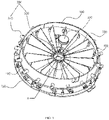
FIG. 1 is a schematic structural diagram of an effect device easy to mount according to one embodiment of the present invention. -
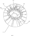
FIG. 2 is a partial enlarged view of part A ofFIG. 1 . -
FIG. 3 is a schematic structural diagram of effect sheets and fixing assemblies in cooperation according to one embodiment of the present invention. -
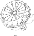
FIG. 4 is a schematic structural diagram of a transmission assembly, in which a gear ring is removed, according to one embodiment of the present invention. - In the drawings: 100 annular frame, 110 mounting hole, 200 effect sheet, 300 fixing assembly, 310 first insertion pin, 311 first protruding portion, 312 connecting hole, 320 second insertion pin, 321 second protruding portion, 400 elastic element, 500 center shaft, 510 inserting hole, 600 driving mechanism, 610 motor, 620 driving wheel, 700 transmission component, 710 transmission shaft, 720 rotating block, 730 shifting rod, 740 gear ring, 750 rotating frame.
- The accompanying drawings of the invention are only for illustrative descriptions and cannot be understood as a limitation to the invention. In order to better illustrate the following embodiments, some parts of the accompanying drawings may be omitted, enlarged or reduced, and do not represent a size of an actual product; and it is understandable for those skilled in the art that some well-known structures in the accompanying drawings and their descriptions may be omitted.
- As shown in
FIG. 1 , an effect device easy to mount is provided, including anannular frame 100, a plurality ofeffect sheets 200 and a plurality offixing assemblies 300 for fixing the plurality ofeffect sheets 200 in theannular frame 100. Each of thefixing assembly 300 includes afirst insertion pin 310 and asecond insertion pin 320 respectively mounted at two ends of eacheffect sheet 200 and used for fixing the plurality ofeffect sheets 200 in theannular frame 100 in a plug-in mode. Thefirst insertion pin 310 is sleeved with anelastic element 400. An end portion of thefirst insertion pin 310 penetrates through amounting hole 110 in theannular frame 100. A first protrudingportion 311 protrudes out of an end, close to theeffect sheets 200, of thefirst insertion pin 310. One end of theelastic element 400 abuts against the first protrudingportion 311, and the other end of theelastic element 400 abuts against an inner side wall of theannular frame 100. Thesecond insertion pin 320 is fixed in the plug-in mode. - According to the device for easily mounting the effect sheets of the present embodiment, the
first insertion pin 310 is sleeved with theelastic element 400, one end of theelastic element 400 abuts against the inner side wall of theannular frame 100, and the other end of theelastic element 400 abuts against the first protrudingportion 311 on thefirst insertion pin 310. Thesecond insertion pin 320 is plugged into the effect sheets. With such configuration, in normal work, eacheffect sheet 200 is fixed by extruding of theelastic element 400. However, in a process of disassembling and assembling theeffect sheets 200, room for thesecond insertion pin 320 to be withdrawn can be made only by compressing theelastic element 400, so that theeffect sheets 200 can be easily and rapidly disassembled and assembled. Therefore, the device according to the present embodiment is simple in disassembling and assembling steps, time for disassembling and assembling the effect sheets is greatly shortened, damage to theeffect sheets 200 in the disassembling and assembling process is relieved, and low producing and maintaining costs are achieved. - In a preferrable embodiment, the mounting
hole 110 is a through hole, thefirst insertion pin 310 may penetrate through the mountinghole 110. With such configuration, when theeffect sheets 200 are disassembled and assembled, more room can be made for thesecond insertion pin 320 to be withdrawn, resulting in simpler and more convenient disassembling and assembling. - As shown in
FIG. 1 , in a preferred embodiment of the invention, theeffect sheets 200 are radially distributed around a center of theannular frame 100. When theannular frame 100 is in circular shape, such design allows theeffect sheets 200 to be consistent in shape and size, causing flexible mounting, batch producing and machining can be performed, thus reducing the cost. - As shown in
FIG. 1 andFIG. 2 , in a preferred embodiment of the invention, acenter shaft 500 located at a center position of theannular frame 100 is provided. Thecenter shaft 500 is provided with an insertinghole 510 for thesecond insertion pin 320 to be inserted. A second protrudingportion 321 protrudes out of an end, close to theeffect sheets 200, of thesecond insertion pin 320, and the second protrudingportion 321 abuts against thecenter shaft 500. Theeffect sheets 200 are fixed between theannular frame 100 and thecenter shaft 500 through thefirst insertion pin 310 and thesecond insertion pin 320, making theeffect sheets 200 distributed radially. By arranging thecenter shaft 500 to mount thesecond insertion pin 320, a distance between two fixed ends of theeffect sheets 200 can be shortened, so that theeffect sheets 200 are mounted more stably, and theeffect sheets 200 are prevented from shaking during work. - Preferably, a diameter of the
second insertion pin 320 is slightly smaller than a diameter of the insertinghole 510, and the diameter of the insertinghole 510 is smaller than a diameter of the second protrudingportion 321. This arrangement enables the second protrudingportion 321 to achieve an abutting action and prevents theeffect sheets 200 from loosening. - Optionally, a top of the
center shaft 500 is provided with a clamping groove and apressing cover 520. The insertinghole 510 is formed by the clamping groove cooperating with thepressing cover 520. When theeffect sheets 200 are completely installed, by press-fitting thepressing cover 520 at an upper end of the clamping groove, and fixedly connecting thepressing cover 520 with thecenter shaft 500 via a screw, thesecond insertion pin 320 is stably fixed to thecenter shaft 500, and theeffect sheets 200 will be not prone to falling off during work. - Preferably, two ends of the
effect sheets 200 connected to the fixingassembly 300 are provided with protrusions, one side of the first protrudingportion 311 and one side of the second protrudingportion 321 close to theeffect sheets 200 are provided with grooves for the protrusions to be inserted. With such design, the protrusion can be fixed to the groove through adhesive dispensing, so that thefirst insertion pin 310 and thesecond insertion pin 320 can be fixed to the two ends of theeffect sheets 200. - In a preferred embodiment of the invention, the
effect sheets 200 are arranged side by side. When theannular frame 100 is in square shape, theeffect sheets 200 are enabled to be consistent in shape and size due to this layout, resulting in flexible mounting, batch producing and machining can be performed, thus reducing the cost. - In a preferred embodiment of the invention, the
second insertion pin 320 penetrates through another mountinghole 110 in theannular frame 100. A second protrudingportion 321 protrudes out of an end, close to theeffect sheets 200, of thesecond insertion pin 320, and the second protrudingportion 321 abuts against the inner side wall of theannular frame 100. With such configuration, the effect device is simple in structure, reducing mounting parts of theeffect sheets 200, and achieving simple mounting of theeffect sheets 200. In mounting process of theeffect sheets 200, thefirst insertion pin 310 is firstly inserted into the mountinghole 110, a distance between theeffect sheets 200 and theannular frame 100 is shortened by compressing theelastic element 400, then thesecond insertion pin 320 is aligned with the other mountinghole 110 to be plugged in, after that, theeffect sheets 200 are loosened, when elasticity of theelastic element 400 recovers, theeffect sheets 200 can be fixed in theannular frame 100. - In some embodiments, except for the
first insertion pin 310, thesecond insertion pin 320 may also be sleeved with anelastic member 400, one end of theelastic element 400 is enabled to abut against the second protrudingportion 321, and the other end of theelastic element 400 abuts against the inner side wall of theannular frame 100. Theelastic member 400 located at thefirst insertion pin 310 exerts pressure A on the effect sheets by abutting against the first protrudingportion 311, and theelastic member 400 located at thesecond insertion pin 320 exerts pressure B on the effect sheets by abutting against the second protrudingportion 321. As pressure A and pressure B are opposite in direction, theeffect sheets 200 will be more closely connected with the fixingassembly 300. - As shown in
FIG. 1 andFIG. 4 , in a preferred embodiment of the invention, the device further includes adriving mechanism 600 driving theeffect sheets 200 to rotate and a transmission component 700 for transmitting power of thedriving mechanism 600 to theeffect sheets 200. The power of thedriving mechanism 600 is conducted to theeffect sheets 200 through the transmission component 700, so that theeffect sheets 200 can rotate by different angles, and the effect device renders effects of light beams passing through it in a gradual change mode. - Preferably, the
driving mechanism 600 includes amotor 610 and adriving wheel 620 fixedly connected to a rotating shaft of themotor 610. - As shown in
FIG. 1 andFIG. 4 , in a preferred embodiment of the invention, the transmission component 700 includes transmission shafts 710 arranged corresponding to the first insertion pins 310 and moving in a circumferential direction of theannular frame 100. Rotating blocks 720 are correspondingly pivoted to the transmission shafts 710. The transmission component further includes shifting rods 730 fixedly connected with the first insertion pins 310. The shifting rod 730 is in sliding connection with the rotating block 720. Due to the fact that the rotating block 720 is pivoted to the transmission shaft 710, when the transmission shaft 710 drives the rotating block 720 to move in a circumferential direction, the rotating block 720 may rotate simultaneously. However, the shifting rod 730 is connected with the rotating block 720 in the sliding mode, the shifting rod 730 may be driven to swing by the circumferential movement of the rotating block 720, so that thefirst insertion pin 310 can rotate by a certain angle, thus achieving a rotating effect of theeffect sheets 200. - As shown in
FIG. 1 , preferably, one end, stretching out of theannular frame 100, of thefirst insertion pin 310 is provided with a connectinghole 312 into which the shifting rod 730 is plugged and fixedly mounted. - In other embodiments, the transmission shafts 710 correspond to the driving
mechanisms 600 one to one, so that each of theeffect sheets 200 can be independently controlled, and each of theeffect sheets 200 in the effect device can rotate by different angles at the same time to render the light beam passing through the effect device to different degrees, for example, light spots exhibit a gradual change effect. - As shown in
FIG. 1 andFIG. 4 , in a preferred embodiment of the invention, the transmission component 700 further includes a gear ring 740 and arotating frame 750. The gear ring 740 coincides with a center shaft of therotating frame 750, therotating frame 750 is fixedly connected with the gear ring 740, the transmission shafts 710 are all fixed to therotating frame 750, and sawteeth on the gear ring 740 are engaged with thedriving wheel 620 of thedriving mechanism 600. In this way, when thedriving wheel 620 rotates, the gear ring 740 is driven to rotate, the transmission shaft 710 can be driven to move at the same speed in the circumferential direction, so that theeffect sheets 200 rotate by a unified angle at a unified speed, and rotating consistency of theeffect sheets 200 is guaranteed. - Preferably, the
rotating frame 750 is fixedly connected above the gear ring 740 by a screw along a light output direction of the light beam passing through theeffect sheets 200, therotating frame 750 is sleeved on an outer side wall of theannular frame 100, and the gear ring 740 is fixedly arranged below theannular frame 100. In this embodiment, the sawteeth on the gear ring 740 are located on an inner side of the gear ring 740, and thedriving wheel 620 is engaged with the gear ring 740 on the inner side of the gear ring 740. - However, in other embodiments, the
rotating frame 750 can be fixedly connected below the gear ring 740 by a screw along a light output direction of the light beam passing through theeffect sheets 200, therotating frame 750 is sleeved on an outer side wall of theannular frame 100, the gear ring 740 is fixedly arranged above theannular frame 100, the sawteeth on the gear ring 740 are located on an outer side of the gear ring 740, and thedriving wheel 620 is engaged with the gear ring 740 on the outer side of the gear ring 740. - As shown in
FIG. 1 andFIG. 4 , in a preferred embodiment of the invention,effect sheets 200 have a first state and a second state. Theeffect sheets 200 are parallel to a center line of theannular frame 100 when theeffect sheets 200 are in the first state. When theeffect sheets 200 are in the second state, an included angle between theeffect sheets 200 and the center line of theannular frame 100 is an acute angle or a right angle. Rotation of theeffect sheets 200 is achieved, and theeffect sheets 200 can adjust the state according to different interpretation needs. When theeffect sheets 200 are in the first state, theeffect sheets 200 are distributed in theannular frame 100 fully, and effects of the light beams passing through theeffect sheets 200 are sufficiently rendered. When the effect sheets are in the second state, theeffect sheets 200 adjust the effect of part of the light beams, different gradually changing light effects may be presented with angle transformation of theeffect sheets 200, obtaining enriched stage effects. If the included angle between theeffect sheets 200 and the center line of theannular frame 100 is in right angle, the light beam will passe through betweenadjacent effect sheets 200, which has no effect rendering role in the light beam. - As shown in
FIG. 1 , in a preferred embodiment of the invention, eacheffect sheet 200 is a frosting sheet. The light beam passing through the frosting sheet may be frosted, making the color and light spots of the light beam uniform. - In other embodiments, the
effect sheets 200 can be a color sheet, so that light beams passing through the color sheet may be colored, presenting different colors of the light beams. During rotation of theeffect sheets 200, the size of color blocks in the formed light spot can change with a rotation angle of theeffect sheets 200. Stage effects thus are enriched by transforming colors. - In other embodiments, each
effect sheet 200 is a gobo which a light beam pass through may form light spots having multiple patterns. When the gobo is in a process of rotation, the patterns in the formed light spot can change shapes according to a rotation angle of the gobo, which presents a vivid stage effect. - Obviously, the above-mentioned embodiments of the invention are merely examples to clearly illustrate the invention, and are not intended to limit the implementation modes of the invention. For those of ordinary skill in the art, other changes or modifications in different forms can also be made on the basis of the above description. It is unnecessary and impossible to list all the implementation modes here. Any modification, equivalent replacement, improvement and the like made within the spirit and principle of the invention shall be included in the protection scope of the claims of the invention.
Claims (10)
- An effect device easy to mount, comprising:an annular frame;a plurality of effect sheets; anda plurality of fixing assemblies for fixing the plurality of effect sheets in the annular frame, each of the plurality of the fixing assemblies having a first insertion pin and a second insertion pin respectively mounted at two ends of the effect sheet and used for fixing the plurality of effect sheets the effect sheets in the annular frame in a plug-in mode,wherein the first insertion pin is sleeved with an elastic element and an end portion of the first insertion pin penetrates through a mounting hole in the annular frame,a first protruding portion protrudes out of an end, close to each effect sheet, of the first insertion pin, one end of the elastic element abuts against the first protruding portion, and the other end of the elastic element abuts against an inner side wall of the annular frame, andthe second insertion pin is fixed in the plug-in mode.
- The effect device easy to mount according to Claim 1, wherein, the plurality of effect sheets are radially distributed around a center of the annular frame.
- The effect device easy to mount according to Claim 2, further comprising a center shaft located at a center position of the annular frame, wherein
the center shaft is provided with an inserting hole for the second insertion pin to be plugged in, a second protruding portion protrudes out of an end, close to each effect sheet, of the second insertion pin, and the second protruding portion abuts against the center shaft. - The effect device easy to mount according to Claim 1, wherein the plurality of effect sheets are arranged side by side.
- The effect device easy to mount according to Claim 4, wherein the second insertion pin penetrates through another mounting hole in the annular frame, a second protruding portion protrudes out of an end, close to each effect sheet, of the second insertion pin, and the second protruding portion abuts against the inner side wall of the annular frame.
- The effect device easy to mount according to Claim 1, further comprising:a driving mechanism driving the plurality of effect sheet to rotate; anda transmission component for transmitting power of the driving mechanism to the plurality of effect sheets.
- The effect device easy to mount according to Claim 6, wherein the transmission component comprises:a plurality of transmission shafts arranged corresponding to the first insertion pins and capable of moving in a circumferential direction of the annular frame, each of the plurality of transmission shafts being pivoted to a rotating block, anda plurality of shifting rods fixedly connected with the respective first insertion pin, each of the plurality of shifting rods being in sliding connection with the rotating block.
- The effect device easy to mount according to Claim 7, wherein the transmission component further comprises a gear ring and a rotating frame,
wherein the gear ring coincides with a center shaft of the rotating frame, the rotating frame is fixedly connected with the gear ring, the plurality of transmission shafts are all fixed to the rotating frame, and sawteeth on the gear ring are engaged with a driving wheel of the driving mechanism. - The effect device easy to mount according to Claim 6, wherein the plurality of effect sheets have a first state and a second state, the plurality of effect sheets are parallel to a center line of the annular frame when the plurality of effect sheets are in the first state, and
when the plurality of effect sheets are in the second state, an included angle between the effect sheets and the center line of the annular frame is an acute angle or a right angle. - The effect device easy to mount according to any one of Claims 1-9, wherein, the plurality of effect sheets are frosting sheets.
Applications Claiming Priority (2)
| Application Number | Priority Date | Filing Date | Title |
|---|---|---|---|
| CN202020139442.5U CN211316050U (en) | 2020-01-21 | 2020-01-21 | An easy-to-install effect device |
| PCT/CN2020/110155 WO2021147308A1 (en) | 2020-01-21 | 2020-08-20 | Easy-to-install effect device |
Publications (3)
| Publication Number | Publication Date |
|---|---|
| EP4095433A1 true EP4095433A1 (en) | 2022-11-30 |
| EP4095433A4 EP4095433A4 (en) | 2023-02-08 |
| EP4095433B1 EP4095433B1 (en) | 2026-01-28 |
Family
ID=72054428
Family Applications (1)
| Application Number | Title | Priority Date | Filing Date |
|---|---|---|---|
| EP20915612.4A Active EP4095433B1 (en) | 2020-01-21 | 2020-08-20 | Easy-to-install effect device |
Country Status (5)
| Country | Link |
|---|---|
| US (1) | US11739913B2 (en) |
| EP (1) | EP4095433B1 (en) |
| CN (1) | CN211316050U (en) |
| DK (1) | DK4095433T3 (en) |
| WO (1) | WO2021147308A1 (en) |
Family Cites Families (11)
| Publication number | Priority date | Publication date | Assignee | Title |
|---|---|---|---|---|
| US1525541A (en) * | 1918-01-10 | 1925-02-10 | Sperry Gyroscope Co Ltd | Shutter for searchlights |
| CN2079704U (en) * | 1990-08-30 | 1991-06-26 | 浙江舞台电子技术研究所 | Lamp colour changer for stage |
| US5186536A (en) * | 1990-09-06 | 1993-02-16 | Vari-Lite, Inc. | Lighting instrument with movable filters and associated actuation mechanism |
| US5882107A (en) * | 1995-11-16 | 1999-03-16 | Vari-Lite, Inc. | Compact luminaire system |
| US20080062684A1 (en) * | 2006-09-07 | 2008-03-13 | Belliveau Richard S | Theatre light apparatus incorporating independently controlled color flags |
| US20100246182A1 (en) * | 2009-03-31 | 2010-09-30 | Robe Lighting | Spring slot&lock quick-change gobo changer system |
| US8797663B1 (en) * | 2011-09-15 | 2014-08-05 | The Boeing Company | Method and apparatus for selective filtering of an illumination device |
| CN103032737B (en) * | 2012-12-18 | 2014-12-24 | 广州市雅江光电设备有限公司 | LED (Light-Emitting Diode) lamp and assembly method thereof |
| CN208920006U (en) * | 2018-09-06 | 2019-05-31 | 广州市浩洋电子股份有限公司 | A detachable effect disc |
| CN109442301A (en) * | 2018-10-19 | 2019-03-08 | 曾瑞宜 | A kind of emergency lighting device convenient for Fast Installation |
| CN111594775B (en) * | 2020-01-21 | 2025-08-29 | 昕诺飞(中国)投资有限公司 | A stage light with additional visual effects |
-
2020
- 2020-01-21 CN CN202020139442.5U patent/CN211316050U/en active Active
- 2020-08-20 WO PCT/CN2020/110155 patent/WO2021147308A1/en not_active Ceased
- 2020-08-20 DK DK20915612.4T patent/DK4095433T3/en active
- 2020-08-20 EP EP20915612.4A patent/EP4095433B1/en active Active
-
2021
- 2021-11-30 US US17/457,015 patent/US11739913B2/en active Active
Also Published As
| Publication number | Publication date |
|---|---|
| US20220082232A1 (en) | 2022-03-17 |
| CN211316050U (en) | 2020-08-21 |
| US11739913B2 (en) | 2023-08-29 |
| DK4095433T3 (en) | 2026-03-09 |
| EP4095433A4 (en) | 2023-02-08 |
| EP4095433B1 (en) | 2026-01-28 |
| WO2021147308A1 (en) | 2021-07-29 |
Similar Documents
| Publication | Publication Date | Title |
|---|---|---|
| CN208442083U (en) | Invisible fan with simplified structure and fan lamp using the invisible fan | |
| US20110235332A1 (en) | Ornamental module and ornament device thereof | |
| US11739913B2 (en) | Effect device easy to mount | |
| CN106907624A (en) | A kind of Novel reflectoscope and its application method | |
| CN117605198B (en) | A unitized curtain wall based on rapid installation of lighting fixtures | |
| CN222230338U (en) | A colorful color plate and lamp that is easy to assemble | |
| EP3875843A1 (en) | Stage lamp with additional visual effect | |
| CN207440510U (en) | A kind of projecting lamp for rolling projection pattern | |
| CN222047610U (en) | A gear deformation device for lamps | |
| CN209325495U (en) | A kind of multiple groups are spliced to follow stage lighting automatically | |
| CN209245954U (en) | A kind of disc type prismatic disk combination unit of stage lamp | |
| CN222142935U (en) | A lamp connecting rod deformation device | |
| CN201885155U (en) | Light beam local change device | |
| CN212618121U (en) | Color chip transmission device for light rendering and light rendering device | |
| CN223985105U (en) | A stage light frame fixing structure | |
| CN220749971U (en) | Structure for adjusting irradiation angle of green light | |
| CN221897678U (en) | Solar trotting horse lamp with changeable light and shadow | |
| CN223796810U (en) | Transmission device and lighting fixture | |
| CN207230324U (en) | Headlamp | |
| CN221463705U (en) | Line lamp connection structure | |
| CN109611775A (en) | A kind of disc type prismatic disk combination unit of stage lamp | |
| CN221402903U (en) | Pendant lamp convenient to disassemble and assemble | |
| CN223153412U (en) | Light filtering device and stage lamp having the same | |
| CN215634745U (en) | Combined split-change speed-changing device | |
| CN2849464Y (en) | 720 deg rotary mirror ball lamp |
Legal Events
| Date | Code | Title | Description |
|---|---|---|---|
| STAA | Information on the status of an ep patent application or granted ep patent |
Free format text: STATUS: THE INTERNATIONAL PUBLICATION HAS BEEN MADE |
|
| PUAI | Public reference made under article 153(3) epc to a published international application that has entered the european phase |
Free format text: ORIGINAL CODE: 0009012 |
|
| STAA | Information on the status of an ep patent application or granted ep patent |
Free format text: STATUS: REQUEST FOR EXAMINATION WAS MADE |
|
| 17P | Request for examination filed |
Effective date: 20211215 |
|
| AK | Designated contracting states |
Kind code of ref document: A1 Designated state(s): AL AT BE BG CH CY CZ DE DK EE ES FI FR GB GR HR HU IE IS IT LI LT LU LV MC MK MT NL NO PL PT RO RS SE SI SK SM TR |
|
| A4 | Supplementary search report drawn up and despatched |
Effective date: 20230109 |
|
| RIC1 | Information provided on ipc code assigned before grant |
Ipc: F21W 131/406 20000101ALI20230102BHEP Ipc: F21W 131/105 20000101ALI20230102BHEP Ipc: F21V 17/16 20000101ALI20230102BHEP Ipc: F21S 10/00 20000101AFI20230102BHEP |
|
| DAV | Request for validation of the european patent (deleted) | ||
| DAX | Request for extension of the european patent (deleted) | ||
| GRAP | Despatch of communication of intention to grant a patent |
Free format text: ORIGINAL CODE: EPIDOSNIGR1 |
|
| STAA | Information on the status of an ep patent application or granted ep patent |
Free format text: STATUS: GRANT OF PATENT IS INTENDED |
|
| INTG | Intention to grant announced |
Effective date: 20250709 |
|
| GRAJ | Information related to disapproval of communication of intention to grant by the applicant or resumption of examination proceedings by the epo deleted |
Free format text: ORIGINAL CODE: EPIDOSDIGR1 |
|
| STAA | Information on the status of an ep patent application or granted ep patent |
Free format text: STATUS: REQUEST FOR EXAMINATION WAS MADE |
|
| GRAP | Despatch of communication of intention to grant a patent |
Free format text: ORIGINAL CODE: EPIDOSNIGR1 |
|
| STAA | Information on the status of an ep patent application or granted ep patent |
Free format text: STATUS: GRANT OF PATENT IS INTENDED |
|
| INTG | Intention to grant announced |
Effective date: 20251021 |
|
| GRAS | Grant fee paid |
Free format text: ORIGINAL CODE: EPIDOSNIGR3 |
|
| GRAA | (expected) grant |
Free format text: ORIGINAL CODE: 0009210 |
|
| STAA | Information on the status of an ep patent application or granted ep patent |
Free format text: STATUS: THE PATENT HAS BEEN GRANTED |
|
| AK | Designated contracting states |
Kind code of ref document: B1 Designated state(s): AL AT BE BG CH CY CZ DE DK EE ES FI FR GB GR HR HU IE IS IT LI LT LU LV MC MK MT NL NO PL PT RO RS SE SI SK SM TR |
|
| REG | Reference to a national code |
Ref country code: CH Ref legal event code: F10 Free format text: ST27 STATUS EVENT CODE: U-0-0-F10-F00 (AS PROVIDED BY THE NATIONAL OFFICE) Effective date: 20260128 Ref country code: GB Ref legal event code: FG4D |
|
| REG | Reference to a national code |
Ref country code: NL Ref legal event code: FP |
|
| REG | Reference to a national code |
Ref country code: DE Ref legal event code: R096 Ref document number: 602020066362 Country of ref document: DE |
|
| REG | Reference to a national code |
Ref country code: IE Ref legal event code: FG4D |
|
| REG | Reference to a national code |
Ref country code: DK Ref legal event code: T3 Effective date: 20260306 |